WO2020100907A1 - 物品移載設備(article transfer facility) - Google Patents
物品移載設備(article transfer facility) Download PDFInfo
- Publication number
- WO2020100907A1 WO2020100907A1 PCT/JP2019/044371 JP2019044371W WO2020100907A1 WO 2020100907 A1 WO2020100907 A1 WO 2020100907A1 JP 2019044371 W JP2019044371 W JP 2019044371W WO 2020100907 A1 WO2020100907 A1 WO 2020100907A1
- Authority
- WO
- WIPO (PCT)
- Prior art keywords
- support
- article
- container
- transfer
- transport
- Prior art date
- Legal status (The legal status is an assumption and is not a legal conclusion. Google has not performed a legal analysis and makes no representation as to the accuracy of the status listed.)
- Ceased
Links
Images






Classifications
-
- B—PERFORMING OPERATIONS; TRANSPORTING
- B65—CONVEYING; PACKING; STORING; HANDLING THIN OR FILAMENTARY MATERIAL
- B65G—TRANSPORT OR STORAGE DEVICES, e.g. CONVEYORS FOR LOADING OR TIPPING, SHOP CONVEYOR SYSTEMS OR PNEUMATIC TUBE CONVEYORS
- B65G61/00—Use of pick-up or transfer devices or of manipulators for stacking or de-stacking articles not otherwise provided for
-
- B—PERFORMING OPERATIONS; TRANSPORTING
- B65—CONVEYING; PACKING; STORING; HANDLING THIN OR FILAMENTARY MATERIAL
- B65G—TRANSPORT OR STORAGE DEVICES, e.g. CONVEYORS FOR LOADING OR TIPPING, SHOP CONVEYOR SYSTEMS OR PNEUMATIC TUBE CONVEYORS
- B65G47/00—Article or material-handling devices associated with conveyors; Methods employing such devices
- B65G47/74—Feeding, transfer, or discharging devices of particular kinds or types
- B65G47/90—Devices for picking-up and depositing articles or materials
- B65G47/91—Devices for picking-up and depositing articles or materials incorporating pneumatic, e.g. suction, grippers
-
- B—PERFORMING OPERATIONS; TRANSPORTING
- B25—HAND TOOLS; PORTABLE POWER-DRIVEN TOOLS; MANIPULATORS
- B25J—MANIPULATORS; CHAMBERS PROVIDED WITH MANIPULATION DEVICES
- B25J9/00—Program-controlled manipulators
- B25J9/16—Program controls
-
- B—PERFORMING OPERATIONS; TRANSPORTING
- B25—HAND TOOLS; PORTABLE POWER-DRIVEN TOOLS; MANIPULATORS
- B25J—MANIPULATORS; CHAMBERS PROVIDED WITH MANIPULATION DEVICES
- B25J13/00—Controls for manipulators
- B25J13/08—Controls for manipulators by means of sensing devices, e.g. viewing or touching devices
-
- B—PERFORMING OPERATIONS; TRANSPORTING
- B25—HAND TOOLS; PORTABLE POWER-DRIVEN TOOLS; MANIPULATORS
- B25J—MANIPULATORS; CHAMBERS PROVIDED WITH MANIPULATION DEVICES
- B25J9/00—Program-controlled manipulators
- B25J9/0093—Program-controlled manipulators co-operating with conveyor means
-
- B—PERFORMING OPERATIONS; TRANSPORTING
- B65—CONVEYING; PACKING; STORING; HANDLING THIN OR FILAMENTARY MATERIAL
- B65B—MACHINES, APPARATUS OR DEVICES FOR, OR METHODS OF, PACKAGING ARTICLES OR MATERIALS; UNPACKING
- B65B17/00—Other machines, apparatus, or methods for packaging articles or materials
-
- B—PERFORMING OPERATIONS; TRANSPORTING
- B65—CONVEYING; PACKING; STORING; HANDLING THIN OR FILAMENTARY MATERIAL
- B65G—TRANSPORT OR STORAGE DEVICES, e.g. CONVEYORS FOR LOADING OR TIPPING, SHOP CONVEYOR SYSTEMS OR PNEUMATIC TUBE CONVEYORS
- B65G47/00—Article or material-handling devices associated with conveyors; Methods employing such devices
- B65G47/74—Feeding, transfer, or discharging devices of particular kinds or types
- B65G47/90—Devices for picking-up and depositing articles or materials
-
- B—PERFORMING OPERATIONS; TRANSPORTING
- B65—CONVEYING; PACKING; STORING; HANDLING THIN OR FILAMENTARY MATERIAL
- B65G—TRANSPORT OR STORAGE DEVICES, e.g. CONVEYORS FOR LOADING OR TIPPING, SHOP CONVEYOR SYSTEMS OR PNEUMATIC TUBE CONVEYORS
- B65G57/00—Stacking of articles
- B65G57/02—Stacking of articles by adding to the top of the stack
- B65G57/03—Stacking of articles by adding to the top of the stack from above
- B65G57/04—Stacking of articles by adding to the top of the stack from above by suction or magnetic devices
-
- B—PERFORMING OPERATIONS; TRANSPORTING
- B65—CONVEYING; PACKING; STORING; HANDLING THIN OR FILAMENTARY MATERIAL
- B65G—TRANSPORT OR STORAGE DEVICES, e.g. CONVEYORS FOR LOADING OR TIPPING, SHOP CONVEYOR SYSTEMS OR PNEUMATIC TUBE CONVEYORS
- B65G60/00—Simultaneously or alternatively stacking and de-stacking of articles
-
- B—PERFORMING OPERATIONS; TRANSPORTING
- B65—CONVEYING; PACKING; STORING; HANDLING THIN OR FILAMENTARY MATERIAL
- B65B—MACHINES, APPARATUS OR DEVICES FOR, OR METHODS OF, PACKAGING ARTICLES OR MATERIALS; UNPACKING
- B65B5/00—Packaging individual articles in containers or receptacles, e.g. bags, sacks, boxes, cartons, cans, jars
- B65B5/08—Packaging groups of articles, the articles being individually gripped or guided for transfer to the containers or receptacles
-
- B—PERFORMING OPERATIONS; TRANSPORTING
- B65—CONVEYING; PACKING; STORING; HANDLING THIN OR FILAMENTARY MATERIAL
- B65B—MACHINES, APPARATUS OR DEVICES FOR, OR METHODS OF, PACKAGING ARTICLES OR MATERIALS; UNPACKING
- B65B5/00—Packaging individual articles in containers or receptacles, e.g. bags, sacks, boxes, cartons, cans, jars
- B65B5/10—Filling containers or receptacles progressively or in stages by introducing successive articles, or layers of articles
- B65B5/105—Filling containers or receptacles progressively or in stages by introducing successive articles, or layers of articles by grippers
-
- B—PERFORMING OPERATIONS; TRANSPORTING
- B65—CONVEYING; PACKING; STORING; HANDLING THIN OR FILAMENTARY MATERIAL
- B65G—TRANSPORT OR STORAGE DEVICES, e.g. CONVEYORS FOR LOADING OR TIPPING, SHOP CONVEYOR SYSTEMS OR PNEUMATIC TUBE CONVEYORS
- B65G2201/00—Indexing codes relating to handling devices, e.g. conveyors, characterised by the type of product or load being conveyed or handled
- B65G2201/02—Articles
-
- B—PERFORMING OPERATIONS; TRANSPORTING
- B65—CONVEYING; PACKING; STORING; HANDLING THIN OR FILAMENTARY MATERIAL
- B65G—TRANSPORT OR STORAGE DEVICES, e.g. CONVEYORS FOR LOADING OR TIPPING, SHOP CONVEYOR SYSTEMS OR PNEUMATIC TUBE CONVEYORS
- B65G2201/00—Indexing codes relating to handling devices, e.g. conveyors, characterised by the type of product or load being conveyed or handled
- B65G2201/02—Articles
- B65G2201/0235—Containers
- B65G2201/0258—Trays, totes or bins
-
- B—PERFORMING OPERATIONS; TRANSPORTING
- B65—CONVEYING; PACKING; STORING; HANDLING THIN OR FILAMENTARY MATERIAL
- B65G—TRANSPORT OR STORAGE DEVICES, e.g. CONVEYORS FOR LOADING OR TIPPING, SHOP CONVEYOR SYSTEMS OR PNEUMATIC TUBE CONVEYORS
- B65G2203/00—Indexing code relating to control or detection of the articles or the load carriers during conveying
- B65G2203/02—Control or detection
- B65G2203/0208—Control or detection relating to the transported articles
- B65G2203/0233—Position of the article
-
- B—PERFORMING OPERATIONS; TRANSPORTING
- B65—CONVEYING; PACKING; STORING; HANDLING THIN OR FILAMENTARY MATERIAL
- B65G—TRANSPORT OR STORAGE DEVICES, e.g. CONVEYORS FOR LOADING OR TIPPING, SHOP CONVEYOR SYSTEMS OR PNEUMATIC TUBE CONVEYORS
- B65G2203/00—Indexing code relating to control or detection of the articles or the load carriers during conveying
- B65G2203/04—Detection means
- B65G2203/041—Camera
-
- B—PERFORMING OPERATIONS; TRANSPORTING
- B65—CONVEYING; PACKING; STORING; HANDLING THIN OR FILAMENTARY MATERIAL
- B65G—TRANSPORT OR STORAGE DEVICES, e.g. CONVEYORS FOR LOADING OR TIPPING, SHOP CONVEYOR SYSTEMS OR PNEUMATIC TUBE CONVEYORS
- B65G47/00—Article or material-handling devices associated with conveyors; Methods employing such devices
- B65G47/74—Feeding, transfer, or discharging devices of particular kinds or types
- B65G47/90—Devices for picking-up and depositing articles or materials
- B65G47/91—Devices for picking-up and depositing articles or materials incorporating pneumatic, e.g. suction, grippers
- B65G47/917—Devices for picking-up and depositing articles or materials incorporating pneumatic, e.g. suction, grippers control arrangements
Definitions
- the present invention relates to an item transfer facility for transferring an item.
- Patent Document 1 discloses an article including a transfer device (transfer device 3) that transfers an article (article W) from a first support (first container C1) to a second support (second container C2). A transfer facility is disclosed.
- the transfer apparatus takes out the article supported by the first support from the first support, and the article taken out from the first support with respect to the second support. Stow.
- the target corner portion which is one of the plurality of corner portions of the mounting surface of the second support body, is the other one. It is in an inclined posture so that it is located below the corner. Therefore, in addition to the bottom surface of the article housed in the second support being supported by the placement surface of the second support or the top surface of another article adjacent below, the target corner side of the article The side surface is supported by the side wall portion of the second support or the side surface of another article adjacent to the side. This makes it possible to stabilize the posture of the articles stacked on the second support and reduce the possibility of the articles falling or collapsing.
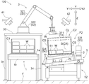
- the article transfer facility 100 will be described below with reference to the drawings.
- the article transfer equipment 100 performs a transfer operation of transferring an article W from the first container C1 to the second container C2.
- the first container C1 and the second container C2 correspond to the “first support” and the “second support” that support the article W, respectively.
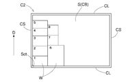
- the second container C2 includes a bottom portion CB having a rectangular placement surface S on which the article W is placed, and a pair of long wall portions CL that stand up from a pair of long sides of the placement surface S. And a pair of short wall portions CS respectively rising from a pair of short sides of the mounting surface S.
- the second container C2 has a rectangular mounting surface S on which the article W is mounted, and is formed in a box shape having an open upper surface.
- the second container C2 is formed in a rectangular parallelepiped shape having an open upper surface.
- the first container C1 is also formed in a rectangular parallelepiped shape having an open upper surface.
- the second container C2 has four corners Sc located at the corners of the mounting surface S.
- a "rectangle" includes a rectangle and a square.
- the article transfer facility 100 includes a first transfer device 1 that transfers a first container C1 and a second transfer device 2 that transfers a second container C2. There is.
- the direction in which the first container C1 and the second container C2 are transported is referred to as the “transport direction X”, and the downstream side and upstream side of the transport direction X are referred to as the “downstream side X1” and the “upstream side X2”, respectively.
- a direction orthogonal to the transport direction X in the vertical direction is referred to as a “transport width direction Y”.
- the vertical direction is referred to as “up and down direction Z”.
- the first transfer device 1 is a device that transfers the first container C1 along the transfer direction X.
- the first transport device 1 is a roller conveyor having a plurality of first rollers 1a.
- Each of the plurality of first rollers 1a has a rotation axis along the transport width direction Y.
- the plurality of first rollers 1a are arranged in the transport direction X such that the first rollers 1a adjacent to each other in the transport direction X are separated from each other.
- the plurality of first rollers 1a are rotatably supported by the first frame 1b.
- a first work position P1 is set on the transfer path of the first transfer device 1.
- the first transport device 1 transports the first container C1 from a first transport source (not shown) to the first work position P1. Then, the first transfer device 1 transfers the first container C1 from the first work position P1 to a first transfer destination (not shown).
- One or more articles W are stored in the first container C1 that is transported to the first work position P1 by the first transport device 1. For example, a plurality of articles W of the same type are stored in one first container C1.
- the first transfer device 1 transfers the first container C1 in a posture in which the short side of the placement surface of the first container C1 is along the transfer direction X.
- the second transfer device 2 is a device that transfers the second container C2 along the transfer direction X.
- the second transport device 2 is a roller conveyor having a plurality of second rollers 2a.
- Each of the plurality of second rollers 2a has a rotation axis extending in the transport width direction Y.
- the plurality of second rollers 2a are arranged in the transport direction X such that the second rollers 2a adjacent to each other in the transport direction X are separated from each other.
- the plurality of second rollers 2a are rotatably supported by the second frame 2b.
- the second transfer device 2 is arranged adjacent to the first transfer device 1 on one side in the transfer width direction Y.
- the first conveyance device 1 side is referred to as the “width direction first side Y1” with respect to the second conveyance device 2, and the opposite side is the “width direction second side Y2”.
- the second transport device 2 is configured such that the short side of the placement surface S of the second container C2 is in a posture along the transport direction X, that is, the short wall portion CS is in a posture along the transport direction X. To transport.
- the second transfer device 2 includes an inclined conveyor 21, an upstream conveyor 22, and a downstream conveyor 23.
- the inclined conveyor 21 is arranged at the second work position P2.
- the inclined conveyance surface 21a which is the conveyance surface of the inclined conveyor 21, is inclined so as to be gradually positioned downward as it goes toward the downstream side X1.
- the upstream conveyor 22 is arranged adjacent to the upstream side X2 with respect to the inclined conveyor 21 so that the first container C1 can be delivered to the inclined conveyor 21.
- the downstream conveyor 23 is arranged adjacent to the downstream side X1 with respect to the inclined conveyor 21 so that the first container C1 can be received from the inclined conveyor 21.
- the upstream transport surface 22a which is the transport surface of the upstream conveyor 22, and the downstream transport surface 23a, which is the transport surface of the downstream conveyor 23, are arranged along a horizontal plane.
- the upstream transport surface 22a is arranged above the downstream transport surface 23a.
- the article transfer facility 100 includes a transfer device 3 that transfers an article W from the first container C1 to the second container C2.
- the transfer device 3 transfers the articles W stored in the first container C1 at the first work position P1 to the second container C2 at the second work position P2. That is, the transfer device 3 stacks the article W supported by the first container C1 in the first operation of taking out the article W from the first container C1 and the article W taken out of the first container C1 in the second container C2.
- the second operation is performed.
- the transfer device 3 includes a holding unit 31 that holds the article W and a moving mechanism 32 that moves the holding unit 31.
- the holding unit 31 has a plurality (three in this example) of suction pads 311.
- the suction pad 311 is configured to be switchable between a suction state that acts on the suction target (article W) and a non-suction state that does not work on the suction target.
- the suction pad 311 sucks the suction target by setting a negative pressure in the space between the suction pad 311 and the suction target while being in contact with the suction target.
- the holding unit 31 holds the article W by adsorbing a part or all of the suction pads 311 on the upper surface of the article W.
- the moving mechanism 32 has a multi-joint arm 321 configured to be bendable and extendable, and a rotating portion 322 that rotates the multi-joint arm 321 around a rotation axis along the vertical direction Z.
- the moving mechanism 32 changes the position and the posture of the holding unit 31 by bending and stretching the multi-joint arm 321 and rotating it by the rotating unit 322.
- the transfer device 3 is mounted on the mounting table 33.
- the mounting table 33 is arranged above the first transfer device 1 so as to cover a part of the first transfer device 1 when viewed in the vertical direction Z.
- the mounting table 33 extends in the vertical direction Z and is supported by a plurality of leg portions 34 installed on the floor surface F.
- the plurality of legs 34 are arranged at positions that do not interfere with the first transport device 1.
- the transfer device 3 is arranged adjacent to the inclined conveyor 21 of the second transfer device 2 on the first side Y1 in the width direction.
- the first work position P1 is set on the downstream side X1 of the mounting table 33 when viewed in the vertical direction Z (see FIG. 1).
- the article transfer facility 100 includes a first imaging device 41 that captures an image of the inside of the first container C1 at the first work position P1, and a second work position P2.
- Second image pickup device 42 for picking up an image of the inside of the second container C2.
- the first imaging device 41 images the inside of the first container C1 at the first work position P1 while the transfer device 3 is performing the first operation.
- the second imaging device 42 images the inside of the second container C2 at the second work position P2 while the transfer device 3 is performing the second operation.
- the first imaging device 41 and the second imaging device 42 are fixed to the fence member 43 that surrounds the installation areas of the first transport device 1, the second transport device 2, and the transfer device 3.
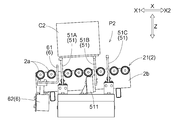
- the article transfer facility 100 includes the tilting device 5 that tilts the second container C2 at the second work position P2.
- the tilting device 5 functions as a “support mechanism” that supports the second container C2 at the specified position.
- the second work position P2 corresponds to the “specified position”.
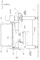
- the tilting device 5 swings the tilting conveyor 21 with respect to the plurality of supporting members 51 that support the second container C2, the plurality of supporting members 51 and the tilting conveyor 21, and the plurality of supporting members 51.
- fluctuation part 53 is provided.
- the plurality of support members 51 are arranged side by side in the transport direction X.
- Each of the plurality of support members 51 is formed in a plate shape extending in the transport width direction Y and the vertical direction Z.
- Each of the plurality of support members 51 is arranged between the second rollers 2 a adjacent to each other in the transport direction X of the inclined conveyor 21.
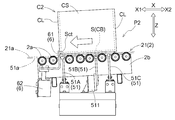
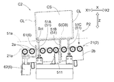
- the plurality of support members 51 are provided in the first support member 51A, the second support member 51B located on the upstream side X2 of the first support member 51A, and the upstream side X2 of the second support member 51B. 51C of 3rd support members located.
- the support surface 51a which is a virtual surface connecting the upper end surfaces of the plurality of support members 51, is located downward as it goes toward the downstream side X1, and goes toward the width direction first side Y1. Is inclined downwards according to. Therefore, when the second container C2 is supported by the plurality of support members 51, one of the four corners Sc of the second container C2 is located below the other corners Sc.
- the corner Sc that is one of the four corners Sc and is located below the other corners Sc is the target corner.
- the part Sct (see FIGS. 2 and 3).
- the tilt angle of the support surface 51a in the carrying direction X and the tilt angle of the carrying width direction Y are the same.
- the transfer device 3 is arranged adjacent to the inclined conveyor 21 of the second transfer device 2 on the first side Y1 in the width direction. Therefore, in the present embodiment, the second container C2 supported by the plurality of support members 51 is inclined so that the mounting surface S is gradually positioned downward as the mounting surface S approaches the transfer device 3.
- the swinging portion 53 swings the inclined conveyor 21 downward with respect to the plurality of support members 51, so that the upper ends of the plurality of support members 51 are located above the inclined transport surface 21 a of the inclined conveyor 21. Is also in a protruding state of protruding upward.
- the swing unit 53 swings the inclined conveyor 21 upward with respect to the plurality of support members 51, so that the upper ends of the plurality of support members 51 are below the inclined transport surface 21 a of the inclined conveyor 21. It will be in the retracted state.
- the second container C2 In the retracted state, the second container C2 is supported only by the inclined transport surface 21a of the inclined transport surface 21a and the support surface 51a.
- the second container C2 is supported by both the inclined transport surface 21a and the support surface 51a. Thereby, the vibration of the second container C2 that occurs during the state change can be suppressed to a small level.
- the second container C2 In the protruding state, the second container C2 is supported only by the support surface 51a of the inclined transport surface 21a and the support surface 51a.
- the target corner Sct which is one of the plurality of corners Sc of the second container C2 is lower than the other corners Sc.
- the 2nd container C2 inclines so that it may be located.
- the article transfer facility 100 includes a receiving device 6 that receives the second container C2 that has been transported to the second work position P2.
- the receiving device 6 includes a receiving body 61 that comes into contact with the second container C2 and receives the second container C2, and a receiving body drive unit 62 that moves the receiving body 61 in the vertical direction Z. There is.
- the receiving device 6 moves the receiving body 61 in the up-down direction Z by the receiving body drive part 62, so that the position of the receiving body 61 is determined such that the upper end portion of the receiving body 61 is more inclined than the inclined transport surface 21a.
- the receiving body 61 is arranged such that the upper end portion of the receiving body 61 is located on the downstream side X1 with respect to the supporting member 51 (the first supporting member 51A in the present embodiment) located on the most downstream side X1.
- the receiving body 61 is formed in an L-shape that extends from the connection portion with the receiving body driving portion 62 to the upstream side X2 and further extends upward when viewed in the transport width direction Y.
- control device 10 causes the swing drive unit 531 to swing the inclined conveyor 21 so that the plurality of support members 51 are in the retracted state, and the receiver drive unit 62 receives the receiver 61. Move to the catch position. In this state, the control device 10 rotationally drives the plurality of second rollers 2a of the second transport device 2 to transport the second container C2 to the second work position P2.
- the control device 10 stops the rotation of the plurality of second rollers 2a after a set time has elapsed since the second container C2 reached the second work position P2. In this way, even after the second container C2 is transported to the second work position P2, the transport operation of the second transport device 2 is continuously performed for the set time. As a result, the second container C2 is pressed against the receiving body 61, so that the second container C2 is transported to the second work position P2 in a posture inclined with respect to the specified direction when viewed in the vertical direction Z. However, the posture of the second container C2 can be corrected to the specified direction.
- control device 10 rotationally drives the plurality of first rollers 1a of the first transport device 1 to transport the first container C1 to the first work position P1, similarly to the control for the second transport device 2.
- the size of the second container C2 is relatively large, and the end portion of the upstream side X2 on the bottom surface of the second container C2 is located on the upstream side X2 with respect to the upper end surface of the third support member 51C.
- the control device 10 causes the support driving unit 511 to move the second support member 51B to the support retreat position.
- the second container C2 is supported by the first support member 51A and the third support member 51C in an inclined state such that the target corner Sct is located below the other corners Sc.
- the size of the second container C2 is relatively small, and the end of the bottom surface of the second container C2 on the upstream side X2 is located at the third end of the second support member 51B in the transport direction X.
- the control device 10 causes the support driving unit 511 to move the second support member 51B to the support position.
- the second container C2 is supported by the first support member 51A and the second support member 51B in an inclined state such that the target corner Sct is located below the other corners Sc.
- control device 10 causes the first imaging device 41 to image the inside of the first container C1 and causes the second imaging device 42 to image the inside of the second container C2. Then, the control device 10 causes the transfer device 3 to perform the first operation and the second operation based on the imaging data of the first imaging device 41 and the second imaging device 42.
- the transfer device 3 is controlled by the control device 10 so as to perform the first operation according to the first coordinate system and the second operation according to the second coordinate system different from the first coordinate system.
- the second coordinate system is inclined with respect to the horizontal plane according to the inclination of the second container C2 supported by the plurality of support members 51.
- the first coordinate system is a three-dimensional orthogonal coordinate system having an x-axis parallel to the transport direction X, a y-axis parallel to the transport width direction Y, and a z-axis parallel to the vertical direction Z. is there.
- the second coordinate system is the x-axis parallel to the short side of the placement surface S of the second container C2 supported by the plurality of supporting members 51, and the second axis supported by the plurality of supporting members 51.
- Two-dimensional orthogonal coordinates having ay axis parallel to the long side of the mounting surface S of the two containers C2 and az axis orthogonal to the mounting surface S of the second container C2 supported by the plurality of support members 51. It is a system.
- the target corner Sct serves as a base point along the short wall portion CS so as to be adjacent to the short wall portion CS.
- the articles W are sequentially placed.
- the reference direction D is set so as to be adjacent to the article W adjacent to the short wall portion CS in a direction orthogonal to the reference direction D.
- the articles W are sequentially placed along the reference direction D from the side near the target corner Sct in.
- the transfer device 3 uses the target corner portion Sct as a base point, and sets the direction along one of the four sides of the mounting surface S as the reference direction D, and sets the reference direction D in the reference direction D.
- the configuration in which the second operation is performed so that the articles W are arranged in order along the above has been described as an example, the configuration is not limited to such a configuration.
- the transfer device 3 may be configured to perform the second operation so that the articles W are arranged in a fan shape when viewed from the direction orthogonal to the mounting surface S with the target corner Sct as a base point. good.
- the transfer device 3 may be configured to perform the second operation by mixing the operation of arranging the articles W in the reference direction D and the operation of arranging the articles W in the direction orthogonal to the reference direction D, or the target corner Sct.
- the transfer device 3 may be configured to perform the second operation based on a location other than the above.
- the configuration in which the tilting device 5 functions as a “support mechanism” that supports the second container C2 at the specified position has been described as an example.
- the second transport device 2 may be configured to function as a “support mechanism”.
- the plurality of second rollers of the second transport device 2 support the second container C2 in a state where the target corner Sct is located below the other corners Sc in the second work position P2. 2a may be arranged.
- the first container C1 has been described as an example in which the first container C1 is formed in the shape of a box having an open upper surface.
- the first container C1 may be a pallet, a skid, or the like.
- the configuration including the first transfer device 1 and the second transfer device 2 has been described as an example.
- the configuration may be such that one of the first transport device 1 and the second transport device 2 is provided, or a configuration that does not include both.
- an operator may supply the first container C1 or the second container C2 to the first work position P1 or the second work position P2.
- the transfer device 3 performs the first operation according to the first coordinate system and is supported by the plurality of support members 51 in the second coordinate system different from the first coordinate system.
- the configuration in which the second operation is performed according to the second coordinate system that is inclined with respect to the horizontal plane according to the inclination of the second container C2 has been described as an example.
- the configuration is not limited to such a configuration, and one or both of the first operation and the second operation may be performed according to a coordinate system different from that of the above-described embodiment.
- the transfer device 3 may perform the first operation and the second operation according to the same coordinate system.
- the coordinate system may have two axes along the horizontal plane, or may have an axis inclined with respect to the horizontal plane.
- the transfer device 3 performs the first operation according to the first coordinate system tilted with respect to the horizontal plane according to the tilt of the second container C2 supported by the plurality of support members 51, and tilts with respect to the horizontal plane.
- the configuration may be such that the second operation is performed according to the second coordinate system that is not performed.
- An article transfer facility for transferring articles Transfer for performing a first operation of taking out the article supported by the first support from the first support and a second operation of stacking the article taken out of the first support on a second support.
- a device A support mechanism that supports the second support at a specified position, The second support has a rectangular mounting surface on which the article is mounted, and is formed in a box shape with an open top surface, The support mechanism is a state in which the second support body is inclined such that a target corner, which is one of the plurality of corners of the placement surface, is located lower than the other corners. Support in.
- the target corner that is one of the plurality of corners of the mounting surface of the second support is the other corner.
- the posture is inclined so that it is located below the above. Therefore, in addition to the bottom surface of the article housed in the second support being supported by the placement surface of the second support or the top surface of another article adjacent below, the target corner side of the article The side surface is supported by the side wall portion of the second support or the side surface of another article adjacent to the side. This makes it possible to stabilize the posture of the articles stacked on the second support and reduce the possibility of the articles falling or collapsing.
- the transfer device performs the first operation according to a first coordinate system and also performs the second operation according to a second coordinate system different from the first coordinate system
- the second coordinate system is preferably tilted with respect to a horizontal plane according to the tilt of the second support body supported by the support mechanism.
- the transfer device uses the target corner portion as a base point, and sets a direction along one of the four sides of the mounting surface as a reference direction, and arranges the articles in order along the reference direction. It is preferable to perform the second operation for a plurality of the articles.
- the side wall portion of the second support can be used to further enhance the stability of the posture of the article on the second support.
- the second support is inclined so that the opening of the second support approaches the transfer device. Therefore, when the transfer device stacks the articles on the second support through the opening of the second support, the transfer distance along the movement trajectory of the articles can be easily shortened. Therefore, the second operation by the transfer device can be efficiently performed.
- the second support can be automatically supplied to the specified position where the support mechanism is arranged, and the second support after the transfer of the article is automatically performed. It can be carried out. Therefore, the transfer operation of the article to the second support can be efficiently performed.
- the technology according to the present disclosure can be used for an item transfer facility that performs an item transfer operation.
- first transfer device 2 second transfer device 3: transfer device 5: tilting device (support mechanism) 51: Support member W: Article C1: First container (first support) C2: Second container (second support) S: mounting surface Sc: corner Sct: target corner P1: first working position P2: second working position (specified position)
Landscapes
- Engineering & Computer Science (AREA)
- Mechanical Engineering (AREA)
- Robotics (AREA)
- Human Computer Interaction (AREA)
- Warehouses Or Storage Devices (AREA)
- Attitude Control For Articles On Conveyors (AREA)
- Container Filling Or Packaging Operations (AREA)
- Specific Conveyance Elements (AREA)
- Intermediate Stations On Conveyors (AREA)
Abstract
Description
物品の移載作業を行う物品移載設備であって、
第1支持体に支持された前記物品を当該第1支持体から取り出す第1動作、及び前記第1支持体から取り出した前記物品を第2支持体に対して積み付ける第2動作を行う移載装置と、
前記第2支持体を規定位置において支持する支持機構と、を備え、
前記第2支持体は、前記物品が載置される矩形状の載置面を有すると共に、上面が開口した箱状に形成され、
前記支持機構は、前記載置面の複数の隅部のうちの1つである対象隅部が、他の前記隅部よりも下方に位置するように、前記第2支持体を傾斜させた状態で支持する点にある。
(1)上記の実施形態では、移載装置3が、対象隅部Sctを基点とし、載置面Sの4つの辺の内の1つに沿う方向を基準方向Dとして、当該基準方向Dに沿って順に物品Wを並べるように第2動作を行う構成を例として説明したが、そのような構成に限定されない。例えば、図12に示すように、移載装置3が、対象隅部Sctを基点とし、載置面Sに直交する方向視で、物品Wを扇状に並べるように第2動作を行う構成としても良い。また、移載装置3が基準方向Dに物品Wを並べる動作と基準方向Dに直交する方向に物品Wを並べる動作とを混在させて第2動作を行う構成としても良いし、対象隅部Sct以外の場所を基点として、移載装置3が第2動作を行う構成としても良い。
以下では、上記において説明した物品移載設備の概要について説明する。
物品の移載作業を行う物品移載設備であって、
第1支持体に支持された前記物品を当該第1支持体から取り出す第1動作、及び前記第1支持体から取り出した前記物品を第2支持体に対して積み付ける第2動作を行う移載装置と、
前記第2支持体を規定位置において支持する支持機構と、を備え、
前記第2支持体は、前記物品が載置される矩形状の載置面を有すると共に、上面が開口した箱状に形成され、
前記支持機構は、前記載置面の複数の隅部のうちの1つである対象隅部が、他の前記隅部よりも下方に位置するように、前記第2支持体を傾斜させた状態で支持する。
前記第2座標系は、前記支持機構によって支持された前記第2支持体の傾斜に応じて水平面に対して傾斜していると好適である。
前記搬送装置の搬送経路における前記規定位置に、前記支持機構が配置されていると好適である。
1 :第1搬送装置
2 :第2搬送装置
3 :移載装置
5 :傾斜装置(支持機構)
51 :支持部材
W :物品
C1 :第1容器(第1支持体)
C2 :第2容器(第2支持体)
S :載置面
Sc :隅部
Sct :対象隅部
P1 :第1作業位置
P2 :第2作業位置(規定位置)
Claims (5)
- 物品の移載作業を行う物品移載設備であって、
第1支持体に支持された前記物品を当該第1支持体から取り出す第1動作、及び前記第1支持体から取り出した前記物品を第2支持体に対して積み付ける第2動作を行う移載装置と、
前記第2支持体を規定位置において支持する支持機構と、を備え、
前記第2支持体は、前記物品が載置される矩形状の載置面を有すると共に、上面が開口した箱状に形成され、
前記支持機構は、前記載置面の複数の隅部のうちの1つである対象隅部が、他の前記隅部よりも下方に位置するように、前記第2支持体を傾斜させた状態で支持する、物品移載設備。 - 前記移載装置は、第1座標系に従って前記第1動作を行うと共に、前記第1座標系とは異なる第2座標系に従って前記第2動作を行い、
前記第2座標系は、前記支持機構によって支持された前記第2支持体の傾斜に応じて水平面に対して傾斜している、請求項1に記載の物品移載設備。 - 前記移載装置は、前記対象隅部を基点とし、前記載置面の4つの辺の内の1つに沿う方向を基準方向として、当該基準方向に沿って順に前記物品を並べるように、複数の前記物品に対する前記第2動作を行う、請求項1又は2に記載の物品移載設備。
- 前記支持機構は、前記載置面が前記移載装置に近づくに従って次第に下方に位置するように、前記第2支持体を傾斜させた状態で支持する、請求項1から3のいずれか一項に記載の物品移載設備。
- 前記第2支持体を搬送する搬送装置を更に備え、
前記搬送装置の搬送経路における前記規定位置に、前記支持機構が配置されている、請求項1から4のいずれか一項に記載の物品移載設備。
Priority Applications (3)
| Application Number | Priority Date | Filing Date | Title |
|---|---|---|---|
| US17/293,635 US12179354B2 (en) | 2018-11-14 | 2019-11-12 | Article transfer facility |
| CN201980075243.2A CN112969654B (zh) | 2018-11-14 | 2019-11-12 | 物品移载设备 |
| KR1020217017801A KR102840488B1 (ko) | 2018-11-14 | 2019-11-12 | 물품 이송탑재 설비 |
Applications Claiming Priority (2)
| Application Number | Priority Date | Filing Date | Title |
|---|---|---|---|
| JP2018213660A JP7134072B2 (ja) | 2018-11-14 | 2018-11-14 | 物品移載設備 |
| JP2018-213660 | 2018-11-14 |
Publications (1)
| Publication Number | Publication Date |
|---|---|
| WO2020100907A1 true WO2020100907A1 (ja) | 2020-05-22 |
Family
ID=70730316
Family Applications (1)
| Application Number | Title | Priority Date | Filing Date |
|---|---|---|---|
| PCT/JP2019/044371 Ceased WO2020100907A1 (ja) | 2018-11-14 | 2019-11-12 | 物品移載設備(article transfer facility) |
Country Status (6)
| Country | Link |
|---|---|
| US (1) | US12179354B2 (ja) |
| JP (1) | JP7134072B2 (ja) |
| KR (1) | KR102840488B1 (ja) |
| CN (1) | CN112969654B (ja) |
| TW (1) | TWI827728B (ja) |
| WO (1) | WO2020100907A1 (ja) |
Families Citing this family (9)
| Publication number | Priority date | Publication date | Assignee | Title |
|---|---|---|---|---|
| JP7147475B2 (ja) * | 2018-10-31 | 2022-10-05 | 株式会社ダイフク | 物品移載設備 |
| JP7294198B2 (ja) * | 2020-03-13 | 2023-06-20 | 株式会社ダイフク | 物品保管設備 |
| CN111645925A (zh) * | 2020-06-15 | 2020-09-11 | 嘉善融汇金属制品有限公司 | 一种板状件包装装置 |
| CN114405834A (zh) * | 2020-10-13 | 2022-04-29 | 菜鸟智能物流控股有限公司 | 数据处理方法、装置、拣选设备、电子设备和存储介质 |
| ES2958564T3 (es) * | 2021-03-03 | 2024-02-09 | Fameccanica Data Spa | Una planta de embalaje y un procedimiento para el embalaje de productos |
| DE202022103747U1 (de) | 2021-07-12 | 2022-10-17 | Hyundai Mobis Co., Ltd. | Led Module |
| US20250058918A1 (en) * | 2023-08-15 | 2025-02-20 | Innovation Associates, Inc. | Multi-bagger linear organizer |
| DE102023134359A1 (de) * | 2023-12-07 | 2025-06-12 | Windmöller & Hölscher Kg | Verfahren zum Ansteuern eines Palettiersystems vor Erreichen von Ende einer Positionierfläche, Computerprogrammprodukt sowie Palettiersystem |
| WO2025248581A1 (ja) * | 2024-05-27 | 2025-12-04 | 株式会社ジェイテック | 移送装置 |
Citations (3)
| Publication number | Priority date | Publication date | Assignee | Title |
|---|---|---|---|---|
| JP2004141980A (ja) * | 2002-10-22 | 2004-05-20 | Todo Seisakusho Ltd | 箱詰め機 |
| JP2014043322A (ja) * | 2012-08-27 | 2014-03-13 | Ntn Corp | 自動箱詰め方法および装置 |
| JP2019042828A (ja) * | 2017-08-30 | 2019-03-22 | 株式会社ダイフク | ピッキング設備 |
Family Cites Families (19)
| Publication number | Priority date | Publication date | Assignee | Title |
|---|---|---|---|---|
| JPH09328225A (ja) * | 1996-06-11 | 1997-12-22 | Kubota Corp | 野菜の取出し装置 |
| JP4830396B2 (ja) * | 2005-08-12 | 2011-12-07 | 澁谷工業株式会社 | 容器収容装置および容器グリッパ |
| JP4835510B2 (ja) * | 2007-05-18 | 2011-12-14 | 株式会社ダイフク | 物品移載装置 |
| TW200936471A (en) | 2008-02-19 | 2009-09-01 | Utechzone Co Ltd | Positioning device and its combination with conveying device |
| CN101726903B (zh) * | 2008-10-13 | 2013-04-24 | 华映视讯(吴江)有限公司 | 治具 |
| JP5574760B2 (ja) * | 2010-03-03 | 2014-08-20 | 株式会社石亀工業 | 傾斜台車 |
| JP5640479B2 (ja) * | 2010-06-09 | 2014-12-17 | 株式会社Ihi | 自動溶接装置における溶接トーチ位置決め方法 |
| DE102011012950B4 (de) * | 2011-03-03 | 2021-05-12 | Grenzebach Maschinenbau Gmbh | Vorrichtung und Verfahren zum definierten Zwischenlagern und Kommisionieren produzierter Waren gleicher Art, aber unterschiedlicher Größe |
| JP5627120B2 (ja) * | 2011-10-17 | 2014-11-19 | 株式会社フジキカイ | 物品搬送装置 |
| JP5590420B2 (ja) * | 2011-12-21 | 2014-09-17 | 株式会社ダイフク | 物品搬送設備 |
| JP6273084B2 (ja) * | 2012-09-20 | 2018-01-31 | 株式会社安川電機 | ロボットシステムおよびワークの搬送方法 |
| JP5752165B2 (ja) * | 2013-03-19 | 2015-07-22 | キヤノン株式会社 | 支持装置および計測装置 |
| CN104752294B (zh) * | 2013-12-27 | 2018-01-09 | 北京北方华创微电子装备有限公司 | 片盒定位装置以及半导体加工设备 |
| JP6614075B2 (ja) * | 2016-09-07 | 2019-12-04 | 株式会社ダイフク | 物品積載設備 |
| HUE040438T2 (hu) * | 2016-09-28 | 2019-03-28 | Int Tobacco Machinery Poland Sp Zoo | Állomás rúdszerû árucikkekkel töltött tálcák számára és berendezés rúdszerû dohányipari árucikkekkel töltött tálcáknak az ürítésére |
| US10336542B2 (en) * | 2016-11-18 | 2019-07-02 | Amazon Technologies, Inc. | Systems and methods for maximizing tote contents |
| TWI600601B (zh) | 2016-11-23 | 2017-10-01 | 住華科技股份有限公司 | 可傾式收集裝置 |
| JP6589847B2 (ja) | 2016-12-26 | 2019-10-16 | 株式会社ダイフク | 物品積載設備 |
| TWI664118B (zh) * | 2017-11-27 | 2019-07-01 | 住華科技股份有限公司 | 承載裝置 |
-
2018
- 2018-11-14 JP JP2018213660A patent/JP7134072B2/ja active Active
-
2019
- 2019-11-12 US US17/293,635 patent/US12179354B2/en active Active
- 2019-11-12 CN CN201980075243.2A patent/CN112969654B/zh active Active
- 2019-11-12 WO PCT/JP2019/044371 patent/WO2020100907A1/ja not_active Ceased
- 2019-11-12 KR KR1020217017801A patent/KR102840488B1/ko active Active
- 2019-11-13 TW TW108141190A patent/TWI827728B/zh active
Patent Citations (3)
| Publication number | Priority date | Publication date | Assignee | Title |
|---|---|---|---|---|
| JP2004141980A (ja) * | 2002-10-22 | 2004-05-20 | Todo Seisakusho Ltd | 箱詰め機 |
| JP2014043322A (ja) * | 2012-08-27 | 2014-03-13 | Ntn Corp | 自動箱詰め方法および装置 |
| JP2019042828A (ja) * | 2017-08-30 | 2019-03-22 | 株式会社ダイフク | ピッキング設備 |
Also Published As
| Publication number | Publication date |
|---|---|
| TW202026217A (zh) | 2020-07-16 |
| JP2020079153A (ja) | 2020-05-28 |
| TWI827728B (zh) | 2024-01-01 |
| KR102840488B1 (ko) | 2025-07-29 |
| JP7134072B2 (ja) | 2022-09-09 |
| KR20210091239A (ko) | 2021-07-21 |
| CN112969654B (zh) | 2023-06-20 |
| US20220009090A1 (en) | 2022-01-13 |
| US12179354B2 (en) | 2024-12-31 |
| CN112969654A (zh) | 2021-06-15 |
Similar Documents
| Publication | Publication Date | Title |
|---|---|---|
| WO2020100907A1 (ja) | 物品移載設備(article transfer facility) | |
| JP7363959B2 (ja) | 物品移載設備 | |
| JP5370664B2 (ja) | 基板の移載装置、およびその方法 | |
| TW201945266A (zh) | 揀貨設備 | |
| WO2020100908A1 (ja) | 物品積載設備(article loading facility) | |
| JP2021130144A (ja) | 保持装置、搬送システム、支持装置、載置方法、及び搬送方法 | |
| JP2021127252A (ja) | 取出装置および方法 | |
| KR102742087B1 (ko) | 물품 반송 설비 | |
| JP6480692B2 (ja) | 集積ヘッド及び箱詰め装置 | |
| JP2021013969A (ja) | 荷役装置、荷役システムおよびプログラム | |
| TWI730134B (zh) | 機器人、機器人之控制方法、教示用治具及機器人之教示方法 | |
| JP2014155965A (ja) | 積載された長方形の被加工材を折曲げ加工機へ供給するローディング装置 | |
| JPH02191106A (ja) | ロボットを用いた箱詰方法 | |
| JP7003893B2 (ja) | 物品移載設備 | |
| JP6900943B2 (ja) | 物品搬送設備 | |
| JP6848676B2 (ja) | ピッキングシステム | |
| JP2021042060A (ja) | 搬送装置 | |
| JP7408135B2 (ja) | ロボットハンドおよび搬送機 | |
| JP3351195B2 (ja) | パレタイズ用ハンド | |
| CN222137905U (zh) | 物品供给装置 | |
| JP6536218B2 (ja) | 昇降搬送装置 | |
| JP2025027541A (ja) | 把持装置、制御方法及びプログラム | |
| JP2021127199A (ja) | ピッキング設備 | |
| JP2020146813A (ja) | 搬送装置 | |
| JPH07330153A (ja) | 物品移載装置 |
Legal Events
| Date | Code | Title | Description |
|---|---|---|---|
| 121 | Ep: the epo has been informed by wipo that ep was designated in this application |
Ref document number: 19885085 Country of ref document: EP Kind code of ref document: A1 |
|
| NENP | Non-entry into the national phase |
Ref country code: DE |
|
| WWE | Wipo information: entry into national phase |
Ref document number: 202147025198 Country of ref document: IN |
|
| ENP | Entry into the national phase |
Ref document number: 20217017801 Country of ref document: KR Kind code of ref document: A |
|
| 122 | Ep: pct application non-entry in european phase |
Ref document number: 19885085 Country of ref document: EP Kind code of ref document: A1 |
|
| WWG | Wipo information: grant in national office |
Ref document number: 1020217017801 Country of ref document: KR |