WO2020044569A1 - ブレーキ診断装置及びブレーキ診断システム - Google Patents
ブレーキ診断装置及びブレーキ診断システム Download PDFInfo
- Publication number
- WO2020044569A1 WO2020044569A1 PCT/JP2018/032490 JP2018032490W WO2020044569A1 WO 2020044569 A1 WO2020044569 A1 WO 2020044569A1 JP 2018032490 W JP2018032490 W JP 2018032490W WO 2020044569 A1 WO2020044569 A1 WO 2020044569A1
- Authority
- WO
- WIPO (PCT)
- Prior art keywords
- brake
- wear
- rotation amount
- amount
- motor
- Prior art date
- Legal status (The legal status is an assumption and is not a legal conclusion. Google has not performed a legal analysis and makes no representation as to the accuracy of the status listed.)
- Ceased
Links
Images










Classifications
-
- B—PERFORMING OPERATIONS; TRANSPORTING
- B60—VEHICLES IN GENERAL
- B60T—VEHICLE BRAKE CONTROL SYSTEMS OR PARTS THEREOF; BRAKE CONTROL SYSTEMS OR PARTS THEREOF, IN GENERAL; ARRANGEMENT OF BRAKING ELEMENTS ON VEHICLES IN GENERAL; PORTABLE DEVICES FOR PREVENTING UNWANTED MOVEMENT OF VEHICLES; VEHICLE MODIFICATIONS TO FACILITATE COOLING OF BRAKES
- B60T17/00—Component parts, details, or accessories of power brake systems not covered by groups B60T8/00, B60T13/00 or B60T15/00, or presenting other characteristic features
- B60T17/18—Safety devices; Monitoring
- B60T17/22—Devices for monitoring or checking brake systems; Signal devices
-
- B—PERFORMING OPERATIONS; TRANSPORTING
- B66—HOISTING; LIFTING; HAULING
- B66B—ELEVATORS; ESCALATORS OR MOVING WALKWAYS
- B66B5/00—Applications of checking, fault-correcting, or safety devices in elevators
-
- F—MECHANICAL ENGINEERING; LIGHTING; HEATING; WEAPONS; BLASTING
- F16—ENGINEERING ELEMENTS AND UNITS; GENERAL MEASURES FOR PRODUCING AND MAINTAINING EFFECTIVE FUNCTIONING OF MACHINES OR INSTALLATIONS; THERMAL INSULATION IN GENERAL
- F16D—COUPLINGS FOR TRANSMITTING ROTATION; CLUTCHES; BRAKES
- F16D66/00—Arrangements for monitoring working conditions, e.g. wear, temperature
Definitions
- the disclosed embodiments relate to a brake diagnosis device and a brake diagnosis system.
- Patent Literature 1 describes a diagnostic device for an elevator magnet brake.
- the diagnostic device includes a current detector that detects a brake operation current, a RAM that temporarily stores a detection result of the detector, and a ROM that stores initial state information extracted from the brake operation current when a brake is newly installed.
- the present invention has been made in view of such a problem, and an object of the present invention is to provide a brake diagnosis device and a brake diagnosis system that can improve the effectiveness of a diagnosis result.
- a brake diagnosis device that diagnoses a brake device of a motor, and a wear amount acquisition unit that acquires a wear amount of a friction material of the brake device;
- a first rotation amount acquisition unit that acquires a total rotation amount that is a cumulative value of the rotation amount of the motor, the wear amount acquired by the wear amount acquisition unit, and a total rotation amount acquired by the first rotation amount acquisition unit.
- a brake diagnostic device having a diagnostic unit that diagnoses wear of the brake device based on the rotation amount is applied.
- a brake diagnostic device for diagnosing a brake device of a motor, wherein a brake operation total rotation amount which is a cumulative value of the rotation amount of the motor at the time of operation of the brake device is calculated.
- a brake diagnostic device comprising: a rotation amount acquisition unit to be acquired; and a diagnosis unit that diagnoses whether the operation state of the brake device is appropriate based on the total rotation amount during the brake operation acquired by the rotation amount acquisition unit. Applied.
- a brake diagnostic device for diagnosing a brake device of a motor, wherein the wear amount acquisition unit acquires a wear amount of a friction material of the brake device, and the wear amount acquisition unit includes: A diagnostic unit that outputs a different diagnostic result for each of the three or more categories of the wear amount based on the acquired wear amount and two or more threshold values set for the wear amount. And a brake diagnostic device having the following.
- the brake diagnostic device a brake power supply device that supplies power to a motor brake device, and a current sensor that detects a current flowing through a brake coil of the brake device. Then, a brake diagnosis system is applied in which the brake diagnosis device, the brake power supply device, and the current sensor are configured separately from a motor control device that controls the motor based on a command from a controller.
- the effectiveness of the diagnosis result can be improved.
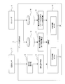
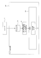
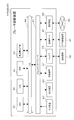
- FIG. 2 is an explanatory diagram illustrating an example of a configuration of a servo system and a brake diagnosis system according to the first embodiment.
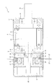
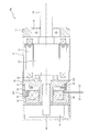
- FIG. 2 is an explanatory diagram illustrating an example of a configuration of a servo motor according to the first embodiment.
- FIG. 2 is an explanatory diagram illustrating an example of a functional configuration of the brake diagnostic device according to the first embodiment.
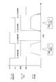
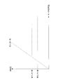
- FIG. 4 is an explanatory diagram illustrating an example of an output of a current sensor when a brake device changes from an operating state to a released state.
- FIG. 9 is an explanatory diagram illustrating an example of a configuration of a servo motor according to a second embodiment.
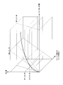
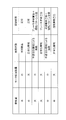
- FIG. 11 is an explanatory diagram illustrating an example of a first threshold value and a second threshold value set for a wear amount and a third threshold value set for a total motor rotation amount in a second embodiment.
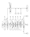
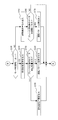
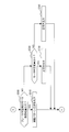
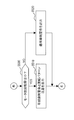
- FIG. 13 is an explanatory diagram illustrating a list of an example of a diagnosis result by a diagnosis unit according to the second embodiment. It is a flowchart showing an example of the brake diagnosis procedure performed by the brake diagnosis device in the second embodiment. It is a flowchart showing an example of the brake diagnosis procedure performed by the brake diagnosis device in the second embodiment. It is a flowchart showing an example of the brake diagnosis procedure performed by the brake diagnosis device in the second embodiment. It is a flowchart showing an example of the brake diagnosis procedure performed by the brake diagnosis device in the second embodiment.
- FIG. 14 is an explanatory diagram illustrating a list of an example of a diagnosis result by a diagnosis unit according to the third embodiment. It is a flow chart showing an example of a brake diagnosis procedure performed by a brake diagnosis device in a 3rd embodiment. It is an explanatory view showing an example of a functional configuration of a brake diagnostic device according to a fourth embodiment.
- FIG. 16 is an explanatory diagram illustrating a list of an example of a diagnosis result by a diagnosis unit according to the fourth embodiment.
- FIG. 13 is a flowchart illustrating an example of a brake diagnosis procedure performed by a brake diagnosis device according to a fourth embodiment. It is an explanatory view showing an example of composition of a servo system and a brake diagnosis system in a modification provided with a voltage sensor.
- FIG. 3 is an explanatory diagram illustrating a hardware configuration example of a brake diagnosis device.
- the servo system 1 includes a controller 3, a motor control device 4, and a servo motor 5.
- the controller 3 is configured by a computer such as a general-purpose personal computer, a PLC (Programmable Logic Controller), and a motion controller.
- the controller 3 generates at least one of a position command, a speed command, and a torque command, and transmits the generated command to the motor control device 4.
- the motor control device 4 controls the servo motor 5 based on a command from the controller 3.
- the servo motor 5 has a motor 6, a brake device 7, and an encoder 8.
- the encoder 8 detects a rotation position, a rotation speed, and the like of the motor 6 and transmits a detection result to the motor control device 4 and the brake diagnosis device 9.
- the brake diagnosis system 2 includes a brake diagnosis device 9, a brake power supply device 10 that supplies power to the brake device 7, a current sensor 11 that detects a current flowing through a brake coil 25 (see FIG. 2 described below) of the brake device 7. , A relay 12 and an A / D converter 13.
- the brake diagnosis system 2 is configured separately from the motor control device 4, and may be configured as a single module (a brake diagnosis module), for example, or may be configured with a plurality of devices.
- the relay 12 is controlled by the brake diagnostic device 9 and the motor control device 4 to open and close the contacts.
- the current sensor 11 transmits the detection result to the brake diagnostic device 9 via the A / D converter 13.
- the configurations of the servo system 1 and the brake diagnosis system 2 are not limited to the above.
- the brake power supply device 10 may be provided outside the brake diagnosis system 2.
- all or a part of the hardware and software of the brake diagnosis system 2 may be implemented in the motor control device 4.
- all or a part of the hardware and software of the brake diagnosis system 2 may be implemented in the controller 3.
- the “load side” refers to the direction in which a load is attached to the servomotor 5, that is, the direction in which the shaft 14 protrudes (right side in FIG. 2) in this example, and the “anti-load side” refers to the load side 2 (left side in FIG. 2).
- the servo motor 5 includes the motor 6, the brake device 7, and the encoder 8.
- the motor 6 includes a shaft 14, a rotor 15, a stator 16, a load-side bracket 17, a load-side bearing 18, a non-load-side bracket 19, and a non-load-side bearing 20.
- the shaft 14 is rotatably supported by the load-side bearing 18 and the non-load-side bearing 20 around the axis AX.
- the non-load side of the shaft 14 protrudes from the non-load side bracket 19, and the brake device 7 and the encoder 8 are provided at the protruding portion.
- the brake device 7 is a non-excitation operation type brake device, and is used as a holding brake for holding the shaft 14 of the motor 6 so as not to move when the power is stopped, for example.
- the brake device 7 has a field core 21, an armature 22, a brake disc 23, and a fixing plate 24.
- the field core 21 has a brake coil 25 and a spring 26.
- the coil end 27 of the brake coil 25 is electrically connected to the brake power supply device 10.
- the armature 22 is supported so as not to rotate with respect to the field core 21 and to be movable in the axial direction of the shaft 14.
- the brake disc 23 is supported via the hub 28 so as to be non-rotatable and axially movable with respect to the shaft 14.
- the brake disc 23 has a friction material 29 on each of a load-side surface and a non-load-side surface.
- the fixing plate 24 is fixed to the non-load-side bracket 19 and the like.
- the brake disc 7 may slip and wear when the brake device 7 is released. At least one of the armature 22 and the fixing plate 24 may come into contact with and wear).
- the configuration of the servo motor 5 is not limited to the above.
- the encoder 8 may be disposed between the motor 6 and the brake device 7, or at least one of the brake device 7 and the encoder 8 may be disposed on the load side of the motor 6.
- the brake diagnosis device 9 includes a wear amount estimation unit 30, a wear amount acquisition unit 31, a first rotation amount recording unit 32, a first rotation amount acquisition unit 33, and a second rotation amount recording unit.
- a section 34, a second rotation amount acquisition section 35, and a diagnosis section 36 are provided.
- the diagnosis unit 36 includes a warning information output unit 37 and a caution information output unit 38.
- the wear amount estimating unit 30 estimates the wear amount of the friction material 29 of the brake disk 23 based on the output of the current sensor 11 that detects the current flowing through the brake coil 25 of the brake device 7. The estimation method by the wear amount estimation unit 30 will be described with reference to FIG.
- FIG. 4 is an explanatory diagram illustrating an example of an output of the current sensor 11 when the brake device 7 changes from an operating state to a released state.
- the brake current starts to flow at timing t1 when the contact of the relay 12 closes, and gradually increases based on a time constant determined by the inductance of the brake coil 25, the winding resistance, and the like.
- the attraction force generated by the brake coil 25 increases with an increase in the brake current, and when the attraction force exceeds the pressing force by the spring 26, the armature 22 moves to the field core 21 and the brake disc 23 is released. You. Since the magnetic flux of the brake coil 25 changes due to the movement of the armature 22 at this time, the brake current is disturbed, and the output of the current sensor 11 temporarily decreases.
- FIG. 4 illustrates three patterns of current waveforms A, B, and C in which the output of the current sensor 11 decreases at times t2, t3, and t4.
- suction time the time required for suctioning the armature 22
- suction time the time required for suctioning the armature 22
- the suction time (t2 ⁇ t1) of the current waveform A since the suction time (t2 ⁇ t1) of the current waveform A is relatively short, it can be estimated that the amount of wear is small. Further, since the suction time (t3 ⁇ t1) of the current waveform B is medium, it can be estimated that the wear amount is also medium. Further, since the suction time (t4 ⁇ t1) of the current waveform C is relatively long, it can be estimated that the amount of wear is large.
- a large wear amount of the friction material 29 is synonymous with a small remaining amount of the friction material 29, and a small wear amount of the friction material 29 is synonymous with a large remaining amount of the friction material 29. is there.
- the wear amount estimating unit 30 determines the residual amount of the friction material 29 of the brake disk 23 based on the output of the current sensor 11. Is estimated.
- the wear amount acquisition unit 31 acquires the wear amount estimated by the wear amount estimation unit 30. As described above, since the wear amount and the remaining amount of the friction material 29 have a two-sided relationship, when obtaining the remaining amount of the friction material 29, the wear amount of the friction material 29 is also obtained. included.
- the first rotation amount recording unit 32 records the total rotation amount of the motor (total rotation amount) which is a cumulative value of the rotation amount of the motor 6 based on the detection signal of the encoder 8.
- the first rotation amount acquisition unit 33 acquires the total rotation amount of the motor from the first rotation amount recording unit 32.
- the “rotation amount” of the motor 6 includes not only the rotation speed ((rotation) of the motor 6 but also the rotation angle ( ⁇ degree, ⁇ radian, etc.). Therefore, the total rotation amount of the motor may be a cumulative value of the number of rotations (up to rotation) or a cumulative value of the rotation angle (up to degree, up to radian, etc.).
- the total motor rotation amount since the total motor rotation amount is a relatively large rotation amount, it is recorded and acquired, for example, as a cumulative value of the rotation speed.
- the second rotation amount recording unit 34 calculates a total rotation amount of the motor 6 during the brake operation (total rotation amount at the time of the brake operation) which is a cumulative value of the rotation amount of the motor 6 during the operation of the brake device 7. ).
- the total motor rotation amount at the time of the brake operation may be the cumulative value of the rotation speed at the time of the brake operation (up to rotation) or the cumulative value of the rotation angle (up to degree, up to radian, etc.). You may.
- the total motor rotation amount during the brake operation is a relatively small rotation amount, it is recorded and acquired, for example, as a cumulative value of the rotation angle.
- the encoder 8 is a so-called batteryless encoder, and can detect and record the rotation amount of the motor 6 even when the power is stopped.
- the second rotation amount recording unit 34 reads the recorded data from the encoder 8 when the power is turned on, and records the total rotation amount of the motor at the time of the brake operation.
- the second rotation amount acquisition unit 35 acquires the total rotation amount of the motor during the brake operation from the second rotation amount recording unit 34.
- the diagnosis unit 36 determines the amount of wear acquired by the wear amount acquisition unit 31, the total rotation amount of the motor acquired by the first rotation amount acquisition unit 33, and the amount of brake operation acquired by the second rotation amount acquisition unit 35.
- the wear of the brake device 7 is diagnosed based on the total rotation amount of the motor. Details of the diagnosis method by the diagnosis unit 36 will be described later.
- the warning information output unit 37 outputs predetermined warning information as a result of diagnosis by the diagnosis unit 36.
- the attention information output unit 38 outputs predetermined attention information as a result of the diagnosis by the diagnosis unit 36. These pieces of output information may be output from an output device 915 (see FIG. 27 described later) such as a display device or an audio output device included in the brake diagnosis device 9, or the motor control device 4 or the controller 3 as necessary. May be sent.
- the processes and the like in the above-described wear amount acquisition unit 31, first rotation amount acquisition unit 33, second rotation amount acquisition unit 35, and the like are not limited to the example of sharing these processes, and for example, are further reduced.
- the processing may be performed by a number of processing units (for example, one processing unit), or may be performed by processing units that are further subdivided.
- Each processing unit of the brake diagnosis device 9 may be implemented by a program executed by a CPU 901 (see FIG. 27) described later, or a part or all of the processing unit may be implemented by an actual ASIC, FPGA, or other electric circuit. It may be implemented by a device.
- a first threshold value and a second threshold value are set for the amount of wear.
- the first threshold value and the second threshold value are set as fixed values.
- the first threshold value and the second threshold value may be set as threshold values that fluctuate according to the total motor rotation amount or the total motor rotation amount at the time of brake operation, for example, using a predetermined formula or table.
- the number of thresholds for the wear amount may be other than 2 (1 or 3 or more).
- a third threshold value is set for the total motor rotation amount.
- the third threshold value is set as a threshold value that increases substantially linearly with an increase in the amount of wear by, for example, a predetermined formula or table. It should be noted that the third threshold value may be a threshold value of another increase / decrease mode, such as a curve increase / decrease mode or a combination of linear and curve increase / decrease modes, or may be a fixed value. Further, the number of thresholds for the total rotation amount of the motor may be two or more.
- the fourth threshold value is set for the total motor rotation amount during the braking operation.
- the fourth threshold value is set as a threshold value that increases substantially linearly with an increase in the amount of wear, for example, using a predetermined formula or table.
- the fourth threshold value may be a threshold value of another increase / decrease mode such as a curve increase / decrease mode, a combination of linear and curve increase / decrease modes, or may be a fixed value.
- the number of thresholds regarding the total rotation amount of the motor at the time of the brake operation may be two or more.
- the diagnosing unit 36 determines the wear amount acquired by the wear amount acquisition unit 31, the first threshold value and the second threshold value set for the wear amount, and the motor total amount acquired by the first rotation amount acquisition unit 33.
- the rotation amount, the third threshold value set for the total rotation amount of the motor, the total rotation amount of the motor during the brake operation acquired by the second rotation amount acquisition unit 35, and the total rotation amount of the motor during the brake operation Based on the determined fourth threshold value, a diagnosis result is output for each of a plurality of sections (in this example, 12 sections) based on the first to fourth threshold values.
- FIG. 6 is an explanatory diagram showing a list of these diagnostic results.
- “large” indicates that the wear amount is equal to or greater than the first threshold
- “medium” indicates that the wear amount is equal to or greater than the second threshold and less than the first threshold
- the case where the amount is less than the second threshold is appropriately described as “small”.
- the case where the total motor rotation amount is equal to or larger than the third threshold value is “large”, and the case where the motor total rotation amount is less than the third threshold value is “small”.
- the case where the total motor rotation amount at the time of the brake operation is equal to or more than the fourth threshold value is “large”, and the case where the total motor rotation amount at the time of the brake operation is less than the fourth threshold value is “small”. It will be described as appropriate.
- the diagnosis unit 36 estimates that the wear amount is small and almost new. A diagnostic result indicating "normal” is output. Similarly, when the wear amount and the total motor rotation amount during the brake operation are both “small” and the total motor rotation amount is “large”, the diagnosis unit 36 determines that the wear amount with respect to the operation time of the motor is small. Since the amount is relatively small, it is estimated that normal wear (slip wear) has occurred, and a diagnosis result indicating "normal” is output.
- the diagnosis unit 36 may determine that the wear due to improper driving is possible. It is presumed that there is, and the caution information output unit 38 outputs “driving pattern caution” (an example of first caution information) urging caution regarding the operation state of the brake device 7. Similarly, when the wear amount is “small” and the total motor rotation amount and the total motor rotation amount during brake operation are both “large”, the diagnosis unit 36 may determine that the wear due to improper driving is possible. The caution information output unit 38 outputs “operating pattern caution”.
- the diagnosis result does not differ depending on the magnitude of the total motor rotation amount, and the magnitude of the total motor rotation amount is determined by the diagnosis result. Does not affect Similarly, when the wear amount is “small” and the total motor rotation amount during the brake operation is “large” as described above, the diagnosis result does not differ depending on the magnitude of the total motor rotation amount. The amount of rotation does not affect the diagnosis result.
- FIG. 7 is an explanatory diagram showing an example of a case where the driving pattern is appropriate and a case where the driving pattern is inappropriate.
- a brake control signal is a signal transmitted from the motor control device 4 or the brake diagnosis device 9 to the relay 12.
- the release time is the time from when the brake control signal is turned ON to when the armature 22 moves to the field core 21 and the brake disk 23 is released.
- the operating time is the time from when the brake control signal is turned OFF to when the armature 22 moves to the brake disk 23 side and the brake disk 23 engages with the armature 22 and the fixed plate 24.
- the actual motor speed is the rotation speed of the motor 6 fed back from the encoder 8.
- Brake devices generally used for industrial machines are not used for braking to stop a rotating motor with a brake, but as in the present embodiment, for example, when the power is stopped, the motor is stopped so that the machine or device does not move. Used for holding. For this reason, the motor and the brake device are preferably used in an operation pattern in which the motor stops while the brake device is operating and the motor is driven while the brake device is released.
- the motor 6 rotates only when the brake device 7 is released (the actual motor speed is higher than 0), and stops when the brake device 7 is operating (the actual motor speed is lower). In the case of 0), it can be estimated that the operation state (driving pattern) of the brake device 7 is appropriate, that is, the brake device 7 is used for holding.
- the brake It can be estimated that the operation status (driving pattern) of the device 7 is inappropriate, that is, there is a status in which the brake device 7 is used not for holding but for braking. In such a case, since the total rotation amount of the motor at the time of the brake operation becomes large, the diagnosis unit 36 outputs the “drive pattern caution” for urging the caution regarding the operation state of the brake device 7 as described above.
- the diagnosis unit 36 determines that the wear amount is large. Assuming that the friction material 29 has reached the end of its life, the warning information output unit 37 outputs a “brake life warning” (an example of first warning information) prompting replacement of the friction material 29 (or the brake device 7). In addition, the diagnostic unit 36 indicates that abnormal wear has occurred because the amount of wear is relatively large with respect to the operation time of the motor, and that the total amount of rotation of the motor when the brake is actuated is small.
- the caution information output section 38 outputs “caution for idling wear” (an example of the second caution information) for urging the user to pay attention to the idling wear of the brake device 7.
- the diagnosis unit 36 determines that the friction material 29 has a life, Since the wear amount is an amount adapted to the operation time of the motor, it is estimated that the wear is normal (idling wear), and the warning information output unit 37 outputs the friction material 29 (or the brake device 7). Outputs only the "brake life warning" urging the replacement of
- the diagnosis unit 36 estimates that the friction material 29 has reached the end of its life when the wear amount and the total motor rotation amount during brake operation are both “large” and the total motor rotation amount is “small”. Then, the warning information output unit 37 outputs a “brake life warning”. In addition, the diagnostic unit 36 indicates that abnormal wear has occurred because the amount of wear is relatively large with respect to the operation time of the motor, and the cause of the abnormal wear is large because the total amount of rotation of the motor during brake operation is large. Presumes that the wear is caused by improper driving, and outputs a “driving pattern caution” prompting the caution regarding the operating state of the brake device 7 by the caution information output unit 38 together with the brake life warning.
- the diagnosis unit 36 estimates that the friction material 29 has reached the end of its life and outputs a warning information output unit. 37 outputs a "brake life warning”. In addition, the diagnosis unit 36 estimates that although the amount of wear is an amount adapted to the operation time of the motor, the total rotation amount of the motor during the brake operation is large, and there is a possibility of wear due to improper operation. Then, the caution information output unit 38 outputs “operation pattern caution”.
- the diagnosis unit 36 determines the wear amount with respect to the motor operation time. Is relatively large, it is estimated that the wear is abnormally progressing, and the warning information output unit 37 indicates that the wear of the friction material 29 is abnormally progressing. (An example of the second warning information and the fourth warning information) is output. In addition, the diagnosis unit 36 estimates that the cause of the abnormal wear is idling wear because the total rotation amount at the time of the brake operation is small, and the cautionary information output unit 38 outputs the idling of the brake device 7 together with the early wear warning. It outputs "idling wear warning" that calls attention to wear.
- the diagnosis unit 36 determines the motor operation time.
- the wear amount is relatively small, it is estimated that the wear (idling wear) is normally in progress, and the warning information output unit 37 indicates that the wear of the friction material 29 is normally in progress. Is output (an example of the second warning information and the third warning information).
- the diagnostic unit 36 On the other hand, since the wear amount is relatively large, it is estimated that the wear is abnormally progressing, and the warning information output unit 37 indicates that the wear of the friction material 29 is abnormally progressing. "Early wear warning” is output. In addition, the diagnosis unit 36 estimates that the cause of the abnormal wear is wear due to improper driving because the total rotation amount of the motor at the time of braking is large, and together with the early wear warning, the caution information output unit 38 As a result, an "operation pattern notice" is output to prompt the user to pay attention to the operation state of the brake device 7.
- the diagnosis unit 36 determines the wear amount with respect to the operation time of the motor. Is relatively small, it is estimated that the wear is normally in progress, and the warning information output unit 37 outputs a “normal wear warning”. In addition, the diagnosing unit 36 estimates that, although the wear is progressing normally, but the total rotation amount of the motor during the brake operation is large, there is a possibility of wear due to improper driving. At the same time, the caution information output section 38 outputs "driving pattern caution" for urging caution regarding the operation state of the brake device 7.
- the output information may be output as, for example, one piece of diagnostic result information without such a distinction.
- the output information may be further subdivided and, for example, three or more types of information may be separately output.
- step S10 the brake diagnostic device 9 turns off the brake control signal, opens the contact of the relay 12, and puts the brake device 7 into the operating state.
- step S20 the brake diagnosis device 9 determines whether the rotation speed of the motor 6 is 0 based on the feedback signal from the encoder 8. If the rotation speed of the motor 6 is not 0 (step S20: NO), the process proceeds to step S30.
- step S30 the brake diagnostic device 9 outputs “driving pattern caution” to prompt the caution regarding the operation state of the brake device 7 by the caution information output unit 38. After that, this flow ends.
- step S20 YES
- step S40 the brake diagnostic device 9 turns on the brake control signal, closes the contact of the relay 12, and puts the brake device 7 in the released state.
- step S50 the brake diagnosis device 9 determines the wear amount of the friction material 29 of the brake disk 23 by the wear amount estimating unit 30 based on the output of the current sensor 11 when the brake device 7 changes from the operating state to the released state. Estimate (see FIG. 4).
- step S60 the brake diagnosis device 9 causes the wear amount acquisition unit 31 to acquire the wear amount estimated in step S50.
- step S70 the brake diagnostic device 9 causes the first rotation amount acquisition unit 33 to acquire the total motor rotation amount recorded in the first rotation amount recording unit 32.
- step S80 the brake diagnostic device 9 causes the second rotation amount acquisition unit 35 to acquire the total motor rotation amount during the brake operation recorded in the second rotation amount recording unit 34.
- step S90 the brake diagnosis device 9 uses the diagnosis unit 36 to determine whether the magnitude of the wear amount of the friction material 29 acquired in step S60 is “large”, “medium”, or “small”. . If the magnitude of the wear amount is “large” (ie, equal to or greater than the first threshold), the process proceeds to step S100 shown in FIG.
- step S100 the brake diagnostic device 9 outputs a “brake life warning” prompting the replacement of the friction material 29 (or the brake device 7) by the warning information output unit 37.
- step S110 the brake diagnosis device 9 uses the diagnosis unit 36 to determine whether or not the total motor rotation amount at the time of the brake operation acquired in step S80 is “large” (whether or not it is equal to or greater than a fourth threshold value). judge. If the total motor rotation amount during the brake operation is “large” (step S110: YES), the process proceeds to step S120.
- step S120 the brake diagnostic device 9 causes the caution information output unit 38 to output “driving pattern caution” urging caution regarding the operation state of the brake device 7. Thereafter, the present flow ends (see FIG. 8).
- step S110 NO
- the process proceeds to step S130.
- step S130 the brake diagnosis device 9 causes the diagnosis unit 36 to determine whether or not the total motor rotation amount acquired in step S70 is “small” (whether or not less than a third threshold). If the total rotation amount of the motor is “large” (step S130: NO), this flow ends (see FIG. 8). On the other hand, if the total motor rotation amount is “small” (step S130: YES), the process proceeds to step S140.
- step S140 the brake diagnosing device 9 causes the caution information output unit 38 to output "caution for idling wear” to urge attention regarding idling wear of the brake device 7. Thereafter, the present flow ends (see FIG. 8).
- step S90 If the magnitude of the wear amount is “medium” in the previous step S90 (if it is equal to or more than the second threshold and less than the first threshold), the process proceeds to step S200 shown in FIG.
- step S200 the brake diagnosis device 9 determines whether or not the total motor rotation amount acquired in step S70 is “small” by the diagnosis unit 36 (whether or not the total rotation amount is less than the third threshold value). Is determined. If the total motor rotation amount is “small” (step S200: YES), the process proceeds to step S210.
- step S210 the brake diagnosis device 9 causes the warning information output unit 37 to output an “early wear warning” indicating that the wear of the friction material 29 is abnormally progressing.
- step S220 the brake diagnosis device 9 uses the diagnosis unit 36 to determine whether or not the total motor rotation amount during the brake operation acquired in step S80 is “large” (whether or not the rotation amount is equal to or greater than a fourth threshold value). judge. If the total motor rotation amount during the braking operation is “large” (step S220: YES), the process proceeds to step S230.
- step S230 the brake diagnostic device 9 causes the caution information output unit 38 to output a "drive pattern caution” that prompts a caution regarding the operation state of the brake device 7. Thereafter, the present flow ends (see FIG. 8).
- step S220 determines whether the total rotation amount of the motor during the brake operation is “small” in step S220. If the total rotation amount of the motor during the brake operation is “small” in step S220 (step S220: NO), the process proceeds to step S240.
- step S240 the brake diagnostic device 9 causes the caution information output unit 38 to output "caution for idling wear” to urge attention regarding idling wear of the brake device 7. Thereafter, the present flow ends (see FIG. 8).
- step S200 determines whether the total motor rotation amount is “large” in step S200 (step S200: NO). If the total motor rotation amount is “large” in step S200 (step S200: NO), the process proceeds to step S250.
- step S250 the brake diagnosis device 9 causes the warning information output unit 37 to output a “normal wear warning” indicating that the wear of the friction material 29 is progressing normally.
- step S260 the brake diagnosis device 9 uses the diagnosis unit 36 to determine whether or not the total motor rotation amount at the time of the brake operation acquired in step S80 is “large” (whether or not it is equal to or greater than a fourth threshold value). judge. When the total rotation amount of the motor at the time of the brake operation is “small” (step S260: NO), this flow is finished (see FIG. 8). On the other hand, if the total motor rotation amount during the brake operation is “large” (step S260: YES), the process proceeds to step S270.
- step S270 the brake diagnostic device 9 causes the caution information output unit 38 to output “driving pattern caution” urging caution regarding the operation state of the brake device 7. Thereafter, the present flow ends (see FIG. 8).
- step S90 If the magnitude of the wear amount is “small” in the previous step S90 (less than the second threshold value), the process proceeds to step S300 shown in FIG.
- step S300 the brake diagnosis device 9 determines whether or not the total motor rotation amount during the brake operation acquired in step S80 is “large” by the diagnosis unit 36 (fourth threshold). Is greater than or equal to the value).
- step S300: YES the process proceeds to step S310.
- step S310 the brake diagnosis device 9 causes the caution information output unit 38 to output "driving pattern caution” urging caution regarding the operation state of the brake device 7. Thereafter, the present flow ends (see FIG. 8).
- step S300 if the total motor rotation amount during the brake operation is “small” (step S300: NO), the process proceeds to step S320.
- step S320 the brake diagnosis device 9 causes the diagnosis unit 36 to determine whether or not the total motor rotation amount acquired in step S70 is “small” (whether or not less than a third threshold). If the total motor rotation amount is “small” (step S320: YES), the process proceeds to step S330.
- step S330 the brake diagnosis device 9 causes the diagnosis unit 36 to output a diagnosis result indicating "normal”. Thereafter, the present flow ends (see FIG. 8).
- step S320 determines whether the total motor rotation amount is “large” in step S320 (step S320: NO). If the total motor rotation amount is “large” in step S320 (step S320: NO), the process proceeds to step S340.
- step S340 the brake diagnosis device 9 causes the diagnosis unit 36 to output a diagnosis result indicating "normal". Thereafter, the present flow ends (see FIG. 8).
- the brake diagnostic device 9 of the present embodiment acquires the motor total rotation amount, which is the cumulative value of the rotation amount of the motor 6, in addition to the wear amount of the friction material 29, and combines these two data.
- the wear amount is an amount adapted to the operation time of the motor 6 or relatively small.
- the wear amount is relatively large with respect to the operation time of the motor 6, so that it can be diagnosed that the wear is caused by some abnormality. In this way, not only the state of wear of the friction material 29 but also whether the wear is normal wear or abnormal wear can be diagnosed, so that the effectiveness of the diagnosis result can be improved.
- the diagnosis unit 36 determines based on the wear amount acquired by the wear amount acquisition unit 31 and two or more first and second threshold values set for the wear amount. When different diagnostic results are output for each of the three or more wear amount categories based on the threshold value, the following effects are obtained.
- the brake diagnosis device 9 includes a second rotation amount obtaining unit 35 that obtains a total rotation amount of the motor during brake operation, which is a cumulative value of the rotation amount of the motor 6 when the brake device 7 is operating.
- the diagnosis unit 36 further includes a wear amount acquired by the wear amount acquisition unit 31, a motor total rotation amount acquired by the first rotation amount acquisition unit 33, and a wear amount acquired by the second rotation amount acquisition unit 35.
- the diagnosis unit 36 obtains the total rotation amount of the motor during braking in addition to the wear amount of the friction material 29 and the total rotation amount of the motor, and diagnoses the wear of the brake device 7 by combining these three data.
- the diagnosis unit 36 obtains the total rotation amount of the motor during braking in addition to the wear amount of the friction material 29 and the total rotation amount of the motor, and diagnoses the wear of the brake device 7 by combining these three data.
- the amount of wear is medium or higher and the total rotation amount of the motor is small (abnormal wear)
- the total rotation amount of the motor is large when the brake is activated
- the motor 6 is largely rotated during the brake operation. Therefore, it can be diagnosed that the abnormal wear is caused by an inappropriate operation state of the brake device 7 (used for braking instead of holding).
- the total rotation amount of the motor at the time of the brake operation is small, it means that abnormal wear occurs while the motor 6 is not rotating at the time of the brake operation. It can be diagnosed that wear has occurred. In this way, when abnormal wear occurs on the friction material 29, the cause can be diagnosed, so that the effectiveness of the diagnosis result can be further improved.
- the diagnosis unit 36 determines that the wear amount acquired by the wear amount acquisition unit 31, the first threshold value set for the wear amount, and the second threshold value smaller than the first threshold value. If the wear amount is equal to or greater than the first threshold value (“large”) based on the value and the “wear warning” prompting replacement of the friction material 29 is output, the wear amount is reduced to the second. If it is not less than the threshold value and less than the first threshold value (“medium”), a “wear warning” (early wear warning or normal wear warning) indicating that the wear of the friction material 29 is in progress is given.
- the warning information output unit 37 for outputting is provided, the following effects are obtained.
- the friction material 29 when the amount of wear is large, the friction material 29 is diagnosed as having a limited life, and the user can be informed of the friction material 29 (or brake) regardless of the total motor rotation amount or the total motor rotation amount during brake operation.
- the replacement of the device 7) can be prompted.
- the wear amount is moderate, the user can be alerted because the wear is in progress although the life is not yet reached.
- the “wear warning” indicates that the wear of the friction material 29 is progressing normally and the “normal wear warning” indicates that the wear of the friction material 29 is progressing abnormally.
- the warning information output unit 37 obtains the first rotation amount when the wear amount is equal to or more than the second threshold value and less than the first threshold value (“medium”). Based on the total motor rotation amount acquired by the unit 33 and the third threshold value set for the total motor rotation amount, the total motor rotation amount is equal to or greater than the third threshold value ("large”). ), A “normal wear warning” is output, and if the total motor rotation amount is less than the third threshold value (“small”), an “early wear warning” is output. The following effects are obtained.
- the amount of wear when the amount of wear is moderate and the total rotation amount of the motor is large, the amount of wear is an amount adapted to the operation time of the motor 6 or relatively small. Can inform the user that the wear is in progress but is still usable because it is normal wear.
- the amount of wear when the amount of wear is moderate and the total rotation amount of the motor is small, it means that the amount of wear is relatively large with respect to the operation time of the motor 6, so that the wear is in progress due to some abnormality. Therefore, it is possible to prompt the user to replace the friction material 29 (the brake device 7) at an early stage although the life is not yet reached.
- the diagnosis unit 36 determines that the total rotation amount of the motor during the brake operation acquired by the second rotation amount acquisition unit 35 and the fourth threshold value set for the total rotation amount of the motor during the brake operation. If the total rotation amount of the motor at the time of the brake operation is equal to or larger than the fourth threshold value (“large”), a “drive pattern caution” prompting a caution regarding the operation state of the brake device 7 is given.
- the cautionary information output unit 38 for outputting is provided, the following effects are obtained.
- the caution information output unit 38 determines that the wear amount is equal to or more than the second threshold value (“medium” or “large”) and the total motor rotation amount is less than the third threshold value (“small”). In some cases, when the total rotation amount of the motor at the time of the brake operation is less than the fourth threshold value (“small”), a “caution about idling wear” that calls attention to idling wear of the brake device 7 is output. Has the following effects.
- the cause of the abnormal wear is when the brake is released. It is possible to diagnose that the wear is caused by idling wear, and to urge the user to replace the friction material 29 (the brake device 7).
- the wear amount estimating unit 30 that estimates the amount of wear of the friction material 29 based on the detection result of the current sensor 11 that detects the current flowing through the brake coil 25 of the brake device 7,
- the wear amount acquisition unit 31 acquires the wear amount estimated by the wear amount estimation unit 30, the following effects are obtained.
- the brake diagnosis system 2 detects a current flowing through the brake diagnosis device 9, a brake power supply device 10 that supplies power to the brake device 7 of the servomotor 5, and a brake coil 25 of the brake device 7.
- a brake diagnostic device 9, a brake power supply device 10, and a current sensor 11 are configured separately from the motor control device 4 that controls the servomotor 5 based on a command from the controller 3. In such a case, the following effects are obtained.
- the brake diagnosis device 9 and the current sensor 11 are integrally mounted on the motor control device, the user needs to replace the existing motor control device with a new motor control device. Increase.
- the development cost is also increased.
- the brake diagnosis device 9, the brake power supply device 10, and the current sensor 11 are configured separately from the motor control device 4.
- the versatility of the motor control device 4 can be maintained, and the user can add the brake diagnosis system 2 as, for example, an external module while using the existing motor control device as it is, so that the introduction cost can be reduced. Further, since it is not necessary to develop a new motor control device model, development costs can be suppressed.
- the servo motor 105 has the motor 6, the brake device 107, and the encoder 8.
- the configurations of the motor 6 and the encoder 8 are the same as those of the first embodiment.
- the brake device 107 is a non-excited operation type brake device as in the first embodiment described above, and is used as a holding brake.
- the brake device 107 has a field core 21, an armature 22, and a brake disc 123.
- the brake disk 123 is fixed to the shaft 14 by a fixing screw (not shown) or the like.
- the brake disk 123 may be fixed to the shaft 14 by, for example, press fitting, bonding, or a fixing tool (such as a rivet) other than the screw, other than the fixing screw.
- the brake disk 123 has the friction material 29 on the surface on the non-load side.
- Other configurations of the brake device 107 are the same as those of the above-described first embodiment.
- the brake device 107 is configured such that a predetermined gap is formed between the friction material 29 of the brake disc 123 and the armature 22 in the released state. For this reason, regardless of the direction and posture of the servo motor 105, basically, no idling wear occurs when the brake device 7 is released.
- the brake diagnosis device 109 includes a wear amount estimation unit 30, a wear amount acquisition unit 31, a first rotation amount recording unit 32, a first rotation amount acquisition unit 33, and a diagnosis unit 136.
- a wear amount estimation unit 30 a wear amount acquisition unit 31
- a first rotation amount recording unit 32 a wear amount acquisition unit 32
- a first rotation amount acquisition unit 33 a wear amount acquisition unit 33
- a diagnosis unit 136 a diagnosis unit 136.
- the second rotation amount recording unit 34 and the second rotation amount acquisition unit 35 are not provided.
- the function of each processing unit is the same as in the first embodiment.
- a first threshold value and a second threshold value are set for the amount of wear.
- the first threshold value and the second threshold value are set as fixed values.
- a third threshold value is set for the total rotation amount of the motor.
- the third threshold value is set as a threshold value that increases substantially linearly with an increase in the total motor rotation amount by, for example, a predetermined formula or table. By setting the third threshold value in this manner, the operation time of the motor can be reflected, and it can be determined whether the motor is new or has been used for a long time.
- the third threshold may be set as a threshold that increases substantially linearly with an increase in the amount of wear.
- the diagnosing unit 136 includes a wear amount acquired by the wear amount acquisition unit 31, a first threshold value and a second threshold value set for the wear amount, and a motor total amount acquired by the first rotation amount acquisition unit 33. Based on the rotation amount and the third threshold value set for the total motor rotation amount, a diagnosis result is output for each of a plurality of sections (six in this example) based on the first to third threshold values.
- FIG. 15 is a diagram for explaining an example of these diagnostic results. Note that “large”, “medium”, and “small” in each threshold value are the same as in the above-described first embodiment (FIG. 6).
- the diagnosis unit 136 estimates that the wear amount is small and almost new, and the diagnosis result indicating “normal” is obtained. Is output. Similarly, when the wear amount is “small” and the total motor rotation amount is “large”, the diagnosis unit 136 indicates that the wear amount is relatively small with respect to the operation time of the motor. , It is estimated that it is normally worn, and a diagnosis result indicating "normal” is output.
- the diagnosis unit 136 estimates that the friction material 29 has reached the end of its life, and the warning information output unit 37 outputs the friction material.
- a "brake life warning" for urging replacement of the brake 29 (or the brake device 7) is output.
- the diagnostic unit 36 has caused abnormal wear because the amount of wear is relatively large with respect to the operation time of the motor, and the cause of the abnormal wear is wear due to improper operation (single-sided brake). Therefore, it is estimated that it is not idling wear), and the caution information output unit 38 outputs “driving pattern caution” for urging caution regarding the operation state of the brake device 7 together with the brake life warning.
- the diagnosis unit 36 determines that although the friction material 29 has a life, the wear amount is an amount adapted to the operation time of the motor. Therefore, it is estimated that the wear is normal, and only the “brake life warning” is output by the warning information output unit 37.
- the diagnosis unit 36 indicates that the wear amount is relatively large with respect to the motor operation time. It is estimated that the wear is abnormally progressing, and the warning information output unit 37 outputs an “early wear warning” indicating that the wear of the friction material 29 is abnormally progressing. In addition, the diagnosis unit 36 estimates that the cause of the abnormal wear is wear due to improper driving (not a slipping wear because of a one-sided brake). The “operation pattern notice” that prompts attention regarding the operation state of the device 7 is output.
- the diagnosis unit 36 indicates that the wear amount is relatively small with respect to the motor operation time. It is estimated that the wear is progressing normally, and the warning information output unit 37 outputs a “normal wear warning” indicating that the wear of the friction material 29 is progressing normally.
- FIG. 16 differs from FIG. 8 described above in that step S80 is not provided. Other procedures are the same as those in FIG.
- step S90 If the magnitude of the amount of wear is “large” in step S90 shown in FIG. 16 (when it is equal to or larger than the first threshold value), the process proceeds to step S400 shown in FIG.
- step S400 the brake diagnostic device 109 causes the warning information output unit 37 to output a “brake life warning” urging replacement of the friction material 29 (or the brake device 7).
- step S410 the brake diagnosis device 109 causes the diagnosis unit 136 to determine whether or not the total motor rotation amount acquired in step S70 is “small” (whether or not less than a third threshold value). If the total rotation amount of the motor is “large” (step S410: NO), this flow ends (see FIG. 16). On the other hand, when the total motor rotation amount is “small” (step S410: YES), the process proceeds to step S420.
- step S420 the brake diagnostic device 109 causes the caution information output unit 38 to output a "driving pattern caution" urging a caution regarding the operation state of the brake device 7. Thereafter, the present flow ends (see FIG. 16).
- step S90 In the case where the magnitude of the wear amount is “medium” in the previous step S90 (in the case where the amount of wear is equal to or more than the second threshold and less than the first threshold), the process proceeds to step S500 shown in FIG.
- step S500 the brake diagnosis device 109 determines whether or not the total motor rotation amount acquired in step S70 is “small” by the diagnosis unit 136 (whether or not the total rotation amount is less than the third threshold value). Is determined. If the total motor rotation amount is “small” (step S500: YES), the process proceeds to step S510.
- step S510 the brake diagnostic device 109 outputs an “early wear warning” indicating that the wear of the friction material 29 is abnormally progressing from the warning information output unit 37, and outputs the brake information from the caution information output unit 38.
- the “operation pattern notice” that prompts attention regarding the operation state of the device 7 is output. Thereafter, the present flow ends (see FIG. 16).
- step S500 determines whether the total motor rotation amount is “large” in step S500 (step S500: NO). If the total motor rotation amount is “large” in step S500 (step S500: NO), the process proceeds to step S520.
- step S520 the brake diagnostic device 109 causes the warning information output unit 37 to output a “normal wear warning” indicating that the wear of the friction material 29 is normally progressing. Thereafter, the present flow ends (see FIG. 16).
- step S90 If the amount of wear is “small” in the previous step S90 (less than the second threshold), the process proceeds to step S600 shown in FIG.
- step S600 the brake diagnostic device 109 determines whether the total motor rotation amount acquired in step S70 is “small” by the diagnostic unit 136 (whether or not less than the third threshold value). Is determined. If the total motor rotation amount is “small” (step S600: YES), the process proceeds to step S610.
- step S610 the brake diagnosis device 109 causes the diagnosis unit 136 to output a diagnosis result indicating "normal”. Thereafter, the present flow ends (see FIG. 16).
- step S600 NO
- the process proceeds to step S620.
- step S620 the brake diagnosis device 109 causes the diagnosis unit 136 to output a diagnosis result indicating “normal”. Thereafter, the present flow ends (see FIG. 16).
- the effectiveness of the diagnosis result of the brake diagnosis device can be improved similarly to the first embodiment.
- the brake diagnosis device 209 includes a second rotation amount recording unit 34, a second rotation amount acquisition unit 35 (an example of a rotation amount acquisition unit), and a diagnosis unit 236.
- the diagnosis unit 236 has an attention information output unit 38.
- the function of each processing unit is the same as that of the first embodiment.
- the fourth threshold value is set for the total rotation amount of the motor during the brake operation.
- the diagnosis unit 236 is configured to determine the second rotation amount based on the total motor rotation amount during the brake operation acquired by the second rotation amount acquisition unit 35 and the fourth threshold value set for the total motor rotation amount during the brake operation.
- the diagnostic result is output for each of a plurality of sections (two sections in this example) based on four thresholds.
- FIG. 21 is a diagram for explaining an example of these diagnostic results. Note that “large” and “small” in the fourth threshold value are the same as in the above-described first embodiment (FIG. 6).
- the diagnosis unit 236 indicates that the motor 6 is almost not rotating at the time of the brake operation. It is estimated that the operation status (operating pattern) is appropriate, that is, it is used for holding, and a diagnosis result indicating that it is “normal” is output.
- the diagnosis unit 236 indicates that the motor 6 is rotating relatively large at the time of the brake operation. It is presumed that the (driving pattern) is inappropriate, that is, it may be used not for holding but for braking, and the caution information output unit 38 prompts the driver to pay attention to the operating condition of the brake device 7. Is output.
- a diagnosis result other than normal is output as caution information, but may be output as information having a higher degree of urgency or importance (for example, warning information).
- steps S10 to S30 and step S80 are the same as those in FIG.
- step S700 the brake diagnosis device 209 determines, by the diagnosis unit 236, whether or not the total motor rotation amount at the time of the brake operation acquired in step S80 is “large” (whether or not it is equal to or more than a fourth threshold value). judge. If the total motor rotation amount during the brake operation is “large” (step S700: YES), the process proceeds to step S710.
- step S710 the brake diagnostic device 209 causes the caution information output unit 38 to output “driving pattern caution” urging caution regarding the operation state of the brake device 7. After that, this flow ends.
- step S700 when the total motor rotation amount during the brake operation is “small” (step S700: NO), the process proceeds to step S720.
- step S720 the brake diagnosis device 209 causes the diagnosis unit 236 to output a diagnosis result indicating that the operation status of the brake device 7 is “normal”. After that, this flow ends.
- the total rotation amount of the motor at the time of the brake operation is obtained, and it is possible to diagnose whether or not the use state of the brake device 7 is appropriate based on this data. Effectiveness can be improved.
- the brake device is diagnosed based on the wear amount and two or more threshold values set for the wear amount.
- the brake diagnosis device 309 includes a wear amount estimation unit 30, a wear amount acquisition unit 31, and a diagnosis unit 336.
- the diagnosis unit 336 has a warning information output unit 37.
- the function of each processing unit is the same as that of the first embodiment.
- the first threshold value and the second threshold value are set for the amount of wear.
- the diagnosis unit 336 determines the first threshold value and the second threshold value based on the wear amount acquired by the wear amount acquisition unit 31 and the first threshold value and the second threshold value set for the wear amount.
- the diagnostic result is output for each of a plurality of sections (three sections in this example) based on the threshold value.
- FIG. 24 is a diagram for explaining an example of these diagnostic results. Note that “large”, “medium”, and “small” in each threshold value are the same as in the above-described first embodiment (FIG. 6).
- the diagnosis unit 336 estimates that the wear is small and is normal, and outputs a diagnosis result indicating “normal”.
- the diagnosis unit 336 estimates that the friction material 29 has reached the end of its life because the wear amount is large, and the warning information output unit 37 outputs the friction material 29 (or the brake device). 7) Output a “brake life warning” prompting replacement.
- the diagnosis unit 336 estimates that the wear is still possible but the wear is in progress, and the warning information output unit 37 indicates that the wear of the friction material 29 is in progress. Is output (an example of the second warning information).
- a diagnosis result other than normal is output as warning information.
- a brake wear warning may be output as information of lower urgency or importance (for example, caution information).
- Step S10 and Steps S40 to S60 are the same as those in FIG. 25
- step S90 the brake diagnosis device 309 causes the diagnosis unit 336 to determine whether the magnitude of the wear amount of the friction material 29 obtained in step S60 is “large”, “medium”, or “small”. . If the size of the wear amount is “large” (when the value is equal to or larger than the first threshold value), the process proceeds to step S800.
- step S800 the brake diagnostic device 309 outputs a “brake life warning” prompting the replacement of the friction material 29 (or the brake device 7) by the warning information output unit 37. After that, this flow ends.
- step S810 if the magnitude of the abrasion amount is “medium” in the previous step S90 (if it is greater than or equal to the second threshold and less than the first threshold), the process proceeds to step S810.
- step S810 the brake diagnosis device 309 causes the warning information output unit 37 to output a “brake wear warning” indicating that the wear of the friction material 29 is in progress. After that, this flow ends.
- step S820 if the magnitude of the wear amount is “small” in the previous step S90 (less than the second threshold value), the process proceeds to step S820.
- step S820 the brake diagnosis device 309 outputs a diagnosis result indicating “normal”. After that, this flow ends.
- the brake device since the brake device is diagnosed based on the amount of wear and two or more threshold values set for the amount of wear, the wear state is simply high (life) or small (normal).
- a diagnostic result for example, a brake wear warning
- a brake wear warning prompts the user to pay attention at an early stage before the end of the life. Therefore, it is possible to prevent the malfunction of the brake device 7 from occurring.
- the wear amount of the friction material 29 is estimated from the suction time of the armature 22 when the brake device 7 is changed from the operation state to the release state based on the output waveform of the current sensor 11 . May be used to estimate the amount of wear. For example, when the amount of wear of the friction material 29 increases, the amount of movement of the armature 22 when the brake device 7 changes from the released state to the operating state increases, so that the time required for releasing the armature 22 (also referred to as “release time”). Becomes longer.
- the brake current starts to decrease from the timing when the contact of the relay 12 opens, and decreases based on a time constant determined by the inductance of the brake coil 25, the winding resistance, and the like.
- the attraction force generated by the brake coil 25 also decreases with a decrease in the brake current, and when the attraction force falls below the pressing force of the spring 26, the armature 22 moves toward the brake disk 23 and the brake disk 23 is engaged. Is done. Since the magnetic flux of the brake coil 25 changes due to the movement of the armature 22 at this time, the brake current is disturbed, and the output of the current sensor 11 temporarily increases. Therefore, based on the output waveform of the current sensor 11, the wear amount of the friction material 29 may be estimated from the release time of the armature 22 when the brake device 7 changes from the released state to the operating state.
- a voltage sensor 39 is provided as shown in FIG.
- the release time of the armature 22 may be detected to estimate the wear amount of the friction material 29.
- a sensor that physically measures the wear amount of the friction material 29 such as an ultrasonic sensor or an optical sensor, may be used.
- the diagnosis method of the first embodiment (FIGS. 3 to 11) is applied to a double-sided brake has been described.
- the diagnosis method of the first embodiment may be applied to a one-sided brake.
- the diagnostic method of the second embodiment (FIGS. 13 to 19) is applied to a single-sided brake has been described.
- the diagnostic method of the second embodiment may be applied to a double-sided brake.
- the diagnostic method of the third embodiment (FIGS. 20 to 22) and the diagnostic method of the fourth embodiment (FIGS. 23 to 25) may be applied to any of the double-sided brake and the single-sided brake.
- two or three of the diagnostic methods of the second to fourth embodiments can be combined and applied to a double-sided brake or a single-sided brake.
- Example of hardware configuration of brake diagnostic device An example of a hardware configuration of the brake diagnosis device 9 that implements the processing by the wear amount acquisition unit 31 or the like implemented by the program executed by the CPU 901 described above will be described with reference to FIG. Note that the same applies to the hardware configuration examples of the brake diagnosis devices 109, 209, and 309 described in the second to fourth embodiments.
- the brake diagnostic device 9 includes a CPU 901, a ROM 903, a RAM 905, a dedicated integrated circuit 907 constructed for a specific use such as an ASIC or an FPGA, an input device 913, and an output device 915. , A recording device 917, a drive 919, a connection port 921, and a communication device 923. These components are connected so that signals can be transmitted to each other via a bus 909 and an input / output interface 911.
- the program can be recorded in, for example, the ROM 903, the RAM 905, the recording device 917, or the like.
- the program can be temporarily or permanently recorded on a magnetic disk such as a flexible disk, an optical disk such as various CD / MO disks / DVDs, or a removable recording medium 925 such as a semiconductor memory.
- a recording medium 925 can be provided as so-called package software.
- the programs recorded on the recording medium 925 may be read by the drive 919 and recorded on the recording device 917 via the input / output interface 911, the bus 909, or the like.
- the program can also be recorded on, for example, a download site, another computer, another recording device, or the like (not shown).
- the program is transferred via a network NW such as a LAN or the Internet, and the communication device 923 receives the program.
- NW such as a LAN or the Internet
- the program received by the communication device 923 may be recorded on the recording device 917 via the input / output interface 911, the bus 909, and the like.
- the program can be recorded in, for example, an appropriate externally connected device 927.
- the program may be transferred through an appropriate connection port 921 and recorded in the recording device 917 via the input / output interface 911, the bus 909, or the like.
- the CPU 901 executes various processes in accordance with the program recorded in the recording device 917, and thereby the processes performed by the wear amount obtaining unit 31, the first rotation amount obtaining unit 33, the second rotation amount obtaining unit 35, and the like. Is realized.
- the CPU 901 may, for example, directly read out the program from the recording device 917 and execute the program, or may execute the program after temporarily loading it in the RAM 905. Further, for example, when the CPU 901 receives a program via the communication device 923, the drive 919, and the connection port 921, the CPU 901 may directly execute the received program without recording it in the recording device 917.
- the CPU 901 may perform various processes based on signals and information input from the input device 913 such as a mouse, a keyboard, and a microphone (not shown), as necessary.
- the input device 913 such as a mouse, a keyboard, and a microphone (not shown), as necessary.
- the CPU 901 may output the result of executing the above processing from an output device 915 such as a display device or a sound output device, and the CPU 901 may transmit the processing result to the communication device 923 or the connection device 923 as necessary.
- the data may be transmitted via the port 921 or may be recorded on the recording device 917 or the recording medium 925.
Landscapes
- Engineering & Computer Science (AREA)
- Mechanical Engineering (AREA)
- General Engineering & Computer Science (AREA)
- Transportation (AREA)
- Braking Arrangements (AREA)
- Valves And Accessory Devices For Braking Systems (AREA)
- Maintenance And Inspection Apparatuses For Elevators (AREA)
Abstract
【課題】診断結果の有効性を向上する。 【解決手段】サーボモータ5のブレーキ装置7を診断するブレーキ診断装置9であって、ブレーキ装置7の摩擦材29の摩耗量を取得する摩耗量取得部31と、モータ6の回転量の累積値であるモータ総回転量を取得する第1回転量取得部33と、摩耗量取得部31により取得された摩耗量及び第1回転量取得部33により取得されたモータ総回転量に基づいてブレーキ装置7の摩耗を診断する診断部36と、を有する。
Description
開示の実施形態は、ブレーキ診断装置及びブレーキ診断システムに関する。
例えば特許文献1には、エレベータ用マグネットブレーキの診断装置が記載されている。この診断装置は、ブレーキ動作電流を検出する電流検出器と、該検出器の検出結果を一時記憶するRAMと、ブレーキの新設時におけるブレーキ動作電流から抽出した初期状態情報を記憶しているROMと、ブレーキ電源回路からの投入指令を確認すると共に、RAMの記憶データを読み出して状態情報を算出し、該状態情報を初期状態情報と比較してブレーキの現時点での状態を診断するCPUとを有する。
上記診断装置においては診断結果の有効性を向上することが要望されている。
本発明はこのような問題点に鑑みてなされたものであり、診断結果の有効性を向上できるブレーキ診断装置及びブレーキ診断システムを提供することを目的とする。
上記課題を解決するため、本発明の一の観点によれば、モータのブレーキ装置を診断するブレーキ診断装置であって、前記ブレーキ装置の摩擦材の摩耗量を取得する摩耗量取得部と、前記モータの回転量の累積値である総回転量を取得する第1回転量取得部と、前記摩耗量取得部により取得された前記摩耗量と、前記第1回転量取得部により取得された前記総回転量と、に基づいて、前記ブレーキ装置の摩耗を診断する診断部と、を有する、ブレーキ診断装置が適用される。
また、本発明の別の観点によれば、モータのブレーキ装置を診断するブレーキ診断装置であって、前記ブレーキ装置の作動時における前記モータの回転量の累積値であるブレーキ作動時総回転量を取得する回転量取得部と、前記回転量取得部により取得された前記ブレーキ作動時総回転量に基づいて、前記ブレーキ装置の動作状況の適否を診断する診断部と、を有する、ブレーキ診断装置が適用される。
また、本発明の別の観点によれば、モータのブレーキ装置を診断するブレーキ診断装置であって、前記ブレーキ装置の摩擦材の摩耗量を取得する摩耗量取得部と、前記摩耗量取得部により取得された前記摩耗量と、前記摩耗量に関して設定された2以上のしきい値と、に基づいて、当該しきい値による3以上の前記摩耗量の区分ごとに異なる診断結果を出力する診断部と、を有する、ブレーキ診断装置が適用される。
また、本発明の別の観点によれば、上記ブレーキ診断装置と、モータのブレーキ装置に電源を供給するブレーキ電源装置と、前記ブレーキ装置のブレーキコイルに流れる電流を検出する電流センサと、を有し、前記ブレーキ診断装置、前記ブレーキ電源装置及び前記電流センサは、コントローラからの指令に基づいて前記モータを制御するモータ制御装置とは別体として構成されている、ブレーキ診断システムが適用される。
本発明のブレーキ診断装置等によれば、診断結果の有効性を向上することができる。
以下、一実施の形態について図面を参照しつつ説明する。
<1.第1実施形態>
まず、第1実施形態について説明する。第1実施形態では、ブレーキディスクの両側の表面に摩擦材が設けられたいわゆる両面ブレーキを診断する。
まず、第1実施形態について説明する。第1実施形態では、ブレーキディスクの両側の表面に摩擦材が設けられたいわゆる両面ブレーキを診断する。
(1-1.サーボシステム、ブレーキ診断システムの構成)
図1を参照しつつ、第1実施形態に係るサーボシステム1と、ブレーキ診断システム2の構成の一例について説明する。
図1を参照しつつ、第1実施形態に係るサーボシステム1と、ブレーキ診断システム2の構成の一例について説明する。
図1に示すように、サーボシステム1は、コントローラ3と、モータ制御装置4と、サーボモータ5とを有する。コントローラ3は、例えば汎用パーソナルコンピュータ、PLC(Programable Logic Controller)、モーションコントローラ等のコンピュータで構成されている。コントローラ3は、位置指令、速度指令、トルク指令の少なくとも1つを生成し、モータ制御装置4に送信する。モータ制御装置4は、コントローラ3からの指令に基づいてサーボモータ5を制御する。
サーボモータ5は、モータ6と、ブレーキ装置7と、エンコーダ8とを有する。エンコーダ8は、モータ6の回転位置や回転速度等を検出し、検出結果をモータ制御装置4及びブレーキ診断装置9に送信する。
ブレーキ診断システム2は、ブレーキ診断装置9と、ブレーキ装置7に電源を供給するブレーキ電源装置10と、ブレーキ装置7のブレーキコイル25(後述の図2参照)に流れる電流を検出する電流センサ11と、リレー12と、A/D変換器13とを有する。ブレーキ診断システム2は、モータ制御装置4とは別体として構成されており、例えば単体のモジュール(ブレーキ診断モジュール)として構成されてもよいし、複数の機器により構成されてもよい。
リレー12は、ブレーキ診断装置9及びモータ制御装置4により接点の開閉を制御される。電流センサ11は、検出結果をA/D変換器13を介してブレーキ診断装置9に送信する。
なお、サーボシステム1やブレーキ診断システム2の構成は、上記に限定されるものではない。例えば、ブレーキ電源装置10は、ブレーキ診断システム2の外部に設けてもよい。また例えば、ブレーキ診断システム2のハードウェア及びソフトウェアの全部又は一部の構成を、モータ制御装置4に実装してもよい。同様に、ブレーキ診断システム2のハードウェア及びソフトウェアの全部又は一部の構成を、コントローラ3に実装してもよい。
(1-2.サーボモータの構成)
図2を参照しつつ、サーボモータ5の構成の一例について説明する。なお、以下において「負荷側」とはサーボモータ5に対して負荷が取り付けられる方向、すなわちこの例ではシャフト14が突出する方向(図2中右側)を指し、「反負荷側」とは負荷側の反対方向(図2中左側)を指す。
図2を参照しつつ、サーボモータ5の構成の一例について説明する。なお、以下において「負荷側」とはサーボモータ5に対して負荷が取り付けられる方向、すなわちこの例ではシャフト14が突出する方向(図2中右側)を指し、「反負荷側」とは負荷側の反対方向(図2中左側)を指す。
上述のように、サーボモータ5は、モータ6と、ブレーキ装置7と、エンコーダ8とを有する。モータ6は、シャフト14と、回転子15と、固定子16と、負荷側ブラケット17と、負荷側軸受18と、反負荷側ブラケット19と、反負荷側軸受20とを有する。シャフト14は、負荷側軸受18及び反負荷側軸受20により軸心AX周りに回転可能に支持される。シャフト14の反負荷側は、反負荷側ブラケット19から突出し、その突出した部分にブレーキ装置7及びエンコーダ8が設けられている。
ブレーキ装置7は、無励磁作動形のブレーキ装置であり、例えば電源停止時等にモータ6のシャフト14が動かないように保持する保持用ブレーキとして使用される。ブレーキ装置7は、フィールドコア21と、アーマチュア22と、ブレーキディスク23と、固定プレート24とを有する。
フィールドコア21は、ブレーキコイル25及びばね26を有する。ブレーキコイル25のコイル端部27は、ブレーキ電源装置10に電気的に接続される。アーマチュア22は、フィールドコア21に対して回転不能且つシャフト14の軸方向に移動可能に支持される。ブレーキディスク23は、ハブ28を介してシャフト14に対し回転不能且つ軸方向に移動可能に支持される。ブレーキディスク23は、負荷側の表面及び反負荷側の表面にそれぞれ摩擦材29を有する。固定プレート24は、反負荷側ブラケット19等に固定されている。
アーマチュア22は、ブレーキコイル25が通電されていない状態(無励磁状態)では、ばね26により負荷側へ押圧され、ブレーキディスク23の摩擦材29がアーマチュア22と固定プレート24とに係合する。この結果、電源停止時等にシャフト14が停止状態で保持される。この状態が、ブレーキ装置7の作動状態である。一方、アーマチュア22は、ブレーキコイル25が通電されている状態(励磁状態)では、ブレーキコイル25による磁気吸引力により反負荷側へ吸引され、ブレーキディスク23が解放される。この結果、シャフト14が回転可能となる。この状態が、ブレーキ装置7の解放状態である。
このように、解放状態においてブレーキディスク23の軸方向位置はフリーな状態となるため、サーボモータ5の向きや姿勢によっては、ブレーキ装置7の解放時に空転摩耗(モータ6の回転時に摩擦材29とアーマチュア22及び固定プレート24の少なくとも一方が接触して摩耗すること)が生じやすくなる可能性がある。
なお、サーボモータ5の構成は、上記に限定されるものではない。例えば、エンコーダ8をモータ6とブレーキ装置7の間に配置してもよいし、ブレーキ装置7又はエンコーダ8の少なくとも一方をモータ6の負荷側に配置してもよい。
(1-3.ブレーキ診断装置の機能構成)
図3及び図4を参照しつつ、ブレーキ診断装置9の機能構成の一例について説明する。
図3及び図4を参照しつつ、ブレーキ診断装置9の機能構成の一例について説明する。
図3に示すように、ブレーキ診断装置9は、摩耗量推定部30と、摩耗量取得部31と、第1回転量記録部32と、第1回転量取得部33と、第2回転量記録部34と、第2回転量取得部35と、診断部36とを有する。診断部36は、警告情報出力部37と、注意情報出力部38とを有する。
摩耗量推定部30は、ブレーキ装置7のブレーキコイル25に流れる電流を検出する電流センサ11の出力に基づいて、ブレーキディスク23の摩擦材29の摩耗量を推定する。この摩耗量推定部30による推定手法について、図4を用いて説明する。
図4は、ブレーキ装置7が作動状態から解放状態となるときの電流センサ11の出力の一例を表す説明図である。図4に示すように、ブレーキ電流は、リレー12の接点が閉じるタイミングt1から流れ始め、ブレーキコイル25のインダクタンス及び巻線抵抗等によって定まる時定数に基づいて緩やかに増加する。ブレーキ電流の増加に伴ってブレーキコイル25が発生する吸引力も増加し、当該吸引力がばね26による押し付け力を上回ったときに、アーマチュア22がフィールドコア21側へ移動してブレーキディスク23が解放される。このときのアーマチュア22の移動によりブレーキコイル25の磁束が変化するので、ブレーキ電流に乱れが生じて電流センサ11の出力が一時的に減少する。図4では、電流センサ11の出力が減少するタイミングがt2,t3,t4である3パターンの電流波形A,B,Cを例示している。
摩擦材29の摩耗量が増加すると、ブレーキ作動時のアーマチュア22とフィールドコア21との距離が増加するため、アーマチュア22の吸引に要する時間(以下「吸引時間」という)が長くなる。図4に示す例では、電流波形Aの吸引時間(t2-t1)は比較的短いため、摩耗量も小さいと推定できる。また、電流波形Bの吸引時間(t3-t1)は中程度であるため、摩耗量も中程度であると推定できる。また、電流波形Cの吸引時間(t4-t1)は比較的長いため、摩耗量も大きいと推定できる。
なお、摩擦材29の摩耗量が大きいことは、摩擦材29の残存量が少ないことと同義であり、摩擦材29の摩耗量が小さいことは、摩擦材29の残存量が多いことと同義である。このように、摩擦材29の摩耗量と残存量とは表裏一体の関係にあることから、摩耗量推定部30は、電流センサ11の出力に基づいて、ブレーキディスク23の摩擦材29の残存量を推定している、ともいうことができる。
摩耗量取得部31は、摩耗量推定部30により推定された摩耗量を取得する。なお、上述のように、摩擦材29の摩耗量と残存量とは表裏一体の関係にあることから、摩擦材29の残存量を取得する場合も、摩擦材29の摩耗量を取得することに含まれる。
第1回転量記録部32は、エンコーダ8の検出信号に基づいて、モータ6の回転量の累積値であるモータ総回転量(総回転量)を記録する。第1回転量取得部33は、この第1回転量記録部32からモータ総回転量を取得する。なお、本実施形態において、モータ6の「回転量」という場合、モータ6の回転数(~回転)だけでなく回転角度(~度、~ラジアン等)をも含むものである。したがって、モータ総回転量は、回転数の累積値(~回転)であってもよいし、回転角度の累積値(~度、~ラジアン等)であってもよい。本実施形態では、モータ総回転量は比較的大きな回転量となることから、例えば回転数の累積値として記録され、取得される。
第2回転量記録部34は、エンコーダ8の検出信号に基づいて、ブレーキ装置7の作動時におけるモータ6の回転量の累積値であるブレーキ作動時のモータ総回転量(ブレーキ作動時総回転量)を記録する。上述のように、ブレーキ作動時のモータ総回転量は、ブレーキ作動時における回転数の累積値(~回転)であってもよいし、回転角度の累積値(~度、~ラジアン等)であってもよい。本実施形態では、ブレーキ作動時のモータ総回転量は比較的小さな回転量となることから、例えば回転角度の累積値として記録され、取得される。なお、エンコーダ8はいわゆるバッテリレスエンコーダであり、電源停止時においてもモータ6の回転量を検出して記録しておくことができる。第2回転量記録部34は、電源投入時にエンコーダ8から上記記録されたデータを読み出し、ブレーキ作動時のモータ総回転量を記録する。第2回転量取得部35は、この第2回転量記録部34からブレーキ作動時のモータ総回転量を取得する。
診断部36は、摩耗量取得部31により取得された摩耗量と、第1回転量取得部33により取得されたモータ総回転量と、第2回転量取得部35により取得されたブレーキ作動時のモータ総回転量とに基づいて、ブレーキ装置7の摩耗を診断する。診断部36による診断手法の詳細については後述する。警告情報出力部37は、診断部36による診断結果として所定の警告情報を出力する。注意情報出力部38は、診断部36による診断結果として所定の注意情報を出力する。これらの出力情報は、例えばブレーキ診断装置9が有する表示装置や音声出力装置等の出力装置915(後述の図27参照)から出力されてもよいし、必要に応じてモータ制御装置4やコントローラ3に送信されてもよい。
なお、上述した摩耗量取得部31、第1回転量取得部33、第2回転量取得部35等における処理等は、これらの処理の分担の例に限定されるものではなく、例えば、更に少ない数の処理部(例えば1つの処理部)で処理されてもよく、また、更に細分化された処理部により処理されてもよい。また、ブレーキ診断装置9の各処理部は、後述するCPU901(図27参照)が実行するプログラムにより実装されてもよいし、その一部又は全部がASICやFPGA、その他の電気回路等の実際の装置により実装されてもよい。
(1-4.診断部の診断手法)
図5~図7を参照しつつ、診断部36による診断手法の一例について説明する。
図5~図7を参照しつつ、診断部36による診断手法の一例について説明する。
図5に示すように、摩耗量には第1しきい値と第2しきい値が設定されている。この例では、第1しきい値と第2しきい値は固定値として設定されている。なお、第1しきい値と第2しきい値を、例えば所定の数式やテーブルによりモータ総回転量やブレーキ作動時のモータ総回転量に応じて変動するしきい値として設定してもよい。また、摩耗量に関するしきい値の数を2以外(1又は3以上)としてもよい。
モータ総回転量には第3しきい値が設定されている。この例では、第3しきい値は例えば所定の数式やテーブルにより摩耗量の増加に応じて略直線的に増加するしきい値として設定されている。なお、第3しきい値を、例えば曲線的な増減態様や直線的及び曲線的な増減態様の組み合わせ等、他の増減態様のしきい値としてもよいし、固定値としてもよい。また、モータ総回転量に関するしきい値の数を2以上としてもよい。
ブレーキ作動時のモータ総回転量には第4しきい値が設定されている。この例では、第4しきい値は例えば所定の数式やテーブルにより摩耗量の増加に応じて略直線的に増加するしきい値として設定されている。なお、第4しきい値を、例えば曲線的な増減態様や直線的及び曲線的な増減態様の組み合わせ等、他の増減態様のしきい値としてもよいし、固定値としてもよい。また、ブレーキ作動時のモータ総回転量に関するしきい値の数を2以上としてもよい。
診断部36は、摩耗量取得部31により取得された摩耗量と、摩耗量に関して設定された第1しきい値及び第2しきい値と、第1回転量取得部33により取得されたモータ総回転量と、モータ総回転量に関して設定された第3しきい値と、第2回転量取得部35により取得されたブレーキ作動時のモータ総回転量と、ブレーキ作動時のモータ総回転量に関して設定された第4しきい値とに基づいて、上記第1~第4しきい値による複数の区分(この例では12区分)ごとに診断結果を出力する。
図6は、これらの診断結果の一覧を表す説明図である。なお、以下では説明の便宜上、摩耗量が第1しきい値以上である場合を「大」、摩耗量が第2しきい値以上かつ第1しきい値未満である場合を「中」、摩耗量が第2しきい値未満である場合を「小」であるとして適宜説明する。また、モータ総回転量が第3しきい値以上である場合を「大」、モータ総回転量が第3しきい値未満である場合を「小」であるとして適宜説明する。また、ブレーキ作動時のモータ総回転量が第4しきい値以上である場合を「大」、ブレーキ作動時のモータ総回転量が第4しきい値未満である場合を「小」であるとして適宜説明する。
図6に示すように、診断部36は、摩耗量、モータ総回転量、ブレーキ作動時のモータ総回転量が全て「小」である場合には、摩耗が少なくほぼ新品であると推定し、「正常」である旨の診断結果を出力する。同様に、診断部36は、摩耗量及びブレーキ作動時のモータ総回転量が共に「小」で、且つ、モータ総回転量が「大」である場合には、モータの運転時間に対して摩耗量が相対的に小さいということであるから、正常に摩耗(空転摩耗)していると推定し、「正常」である旨の診断結果を出力する。
また、診断部36は、摩耗量及びモータ総回転量が共に「小」で、且つ、ブレーキ作動時のモータ総回転量が「大」である場合には、不適切な運転による摩耗の可能性があると推定し、注意情報出力部38によりブレーキ装置7の動作状況に関する注意を促す「運転パターン注意」(第1の注意情報の一例)を出力する。同様に、診断部36は、摩耗量が「小」で、且つ、モータ総回転量及びブレーキ作動時のモータ総回転量が共に「大」である場合には、不適切な運転による摩耗の可能性があると推定し、注意情報出力部38により「運転パターン注意」を出力する。
なお、上記のように摩耗量及びブレーキ作動時のモータ総回転量が共に「小」である場合には、モータ総回転量の大小によって診断結果は異ならず、モータ総回転量の大小は診断結果に影響しない。同様に、上記のように摩耗量が「小」で、且つ、ブレーキ作動時のモータ総回転量が「大」である場合には、モータ総回転量の大小によって診断結果は異ならず、モータ総回転量の大小は診断結果に影響しない。
図7は、運転パターンが適切である場合と不適切である場合の一例を表す説明図である。図7において、ブレーキ制御信号は、モータ制御装置4又はブレーキ診断装置9からリレー12に送信される信号であり、ONでリレー12の接点が閉成し、OFFでリレー12の接点が開成する。また、解放時間は、ブレーキ制御信号がONとなってからアーマチュア22がフィールドコア21側に移動してブレーキディスク23が解放されるまでの時間である。また、作動時間は、ブレーキ制御信号がOFFとなってからアーマチュア22がブレーキディスク23側に移動してブレーキディスク23がアーマチュア22と固定プレート24に係合するまでの時間である。また、モータ実速度は、エンコーダ8からフィードバックされるモータ6の回転速度である。
一般に産業機械に用いられるブレーキ装置は、回転しているモータをブレーキで止める制動用ではなく、本実施形態のように、例えば電源停止時等に機械や装置が動かないようにモータを停止状態で保持する保持用として使用される。このため、モータとブレーキ装置は、ブレーキ装置の作動中にモータが停止し、ブレーキ装置の解放中にモータが駆動されるような運転パターンで使用されるのが好ましい。
したがって、図7の左側に示すように、モータ6がブレーキ装置7の解放状態でのみ回転し(モータ実速度が0より上)、ブレーキ装置7の作動状態では停止している(モータ実速度が0)場合には、ブレーキ装置7の動作状況(運転パターン)が適切である、すなわちブレーキ装置7が保持用として使用されていると推定することができる。一方で、図7の右側に示すように、モータ6がブレーキ装置7の解放状態だけでなく作動状態においても回転している(モータ実速度が0より上の部分がある)場合には、ブレーキ装置7の動作状況(運転パターン)が不適切である、すなわちブレーキ装置7が保持用でなく制動用として使用されている状況があると推定することができる。このような場合には、ブレーキ作動時のモータ総回転量が大きくなることから、上記のように診断部36はブレーキ装置7の動作状況に関する注意を促す「運転パターン注意」を出力する。
図6に戻り、診断部36は、摩耗量が「大」で、且つ、モータ総回転量及びブレーキ作動時のモータ総回転量が共に「小」である場合には、摩耗量が大きいことから摩擦材29が寿命であると推定して、警告情報出力部37により摩擦材29(又はブレーキ装置7)の交換を促す「ブレーキ寿命警告」(第1の警告情報の一例)を出力する。加えて、診断部36は、モータの運転時間に対して摩耗量が相対的に大きいことから異常な摩耗が生じており、且つ、ブレーキ作動時のモータ総回転量が小さいことから異常摩耗の原因は空転摩耗であると推定し、ブレーキ寿命警告と併せて、注意情報出力部38によりブレーキ装置7の空転摩耗に関する注意を促す「空転摩耗注意」(第2の注意情報の一例)を出力する。
また、診断部36は、摩耗量及びモータ総回転量が共に「大」で、且つ、ブレーキ作動時のモータ総回転量が「小」である場合には、摩擦材29は寿命であるけれども、モータの運転時間に対して摩耗量が適応した量であるということであるから、正常に摩耗(空転摩耗)していると推定し、警告情報出力部37により摩擦材29(又はブレーキ装置7)の交換を促す「ブレーキ寿命警告」のみを出力する。
また、診断部36は、摩耗量及びブレーキ作動時のモータ総回転量が共に「大」で、且つ、モータ総回転量が「小」である場合には、摩擦材29が寿命であると推定して警告情報出力部37により「ブレーキ寿命警告」を出力する。加えて、診断部36は、モータの運転時間に対して摩耗量が相対的に大きいことから異常な摩耗が生じており、且つ、ブレーキ作動時のモータ総回転量が大きいことから異常摩耗の原因は不適切な運転による摩耗であると推定し、ブレーキ寿命警告と併せて、注意情報出力部38によりブレーキ装置7の動作状況に関する注意を促す「運転パターン注意」を出力する。
同様に、診断部36は、摩耗量、モータ総回転量、ブレーキ作動時のモータ総回転量が全て「大」である場合には、摩擦材29が寿命であると推定して警告情報出力部37により「ブレーキ寿命警告」を出力する。加えて、診断部36は、モータの運転時間に対して摩耗量が適応した量であるけれども、ブレーキ作動時のモータ総回転量が大きいことから不適切な運転による摩耗の可能性があると推定し、注意情報出力部38により「運転パターン注意」を出力する。
なお、上記のように摩耗量及びブレーキ作動時のモータ総回転量が共に「大」である場合には、モータ総回転量の大小によって診断結果は異ならず、モータ総回転量の大小は診断結果に影響しない。
また、診断部36は、摩耗量が「中」で、且つ、モータ総回転量及びブレーキ作動時のモータ総回転量が共に「小」である場合には、モータの運転時間に対して摩耗量が相対的に大きいということであるから、摩耗が異常に進行中であると推定して、警告情報出力部37により摩擦材29の摩耗が異常に進行中であることを示す「早期摩耗警告」(第2の警告情報、第4の警告情報の一例)を出力する。加えて、診断部36は、ブレーキ作動時総回転量が小さいことから、異常摩耗の原因は空転摩耗であると推定し、早期摩耗警告と併せて、注意情報出力部38によりブレーキ装置7の空転摩耗に関する注意を促す「空転摩耗注意」を出力する。
また、診断部36は、摩耗量が「中」で、モータ総回転量が「大」で、且つ、ブレーキ作動時のモータ総回転量が「小」である場合には、モータの運転時間に対して摩耗量が相対的に小さいということであるから、摩耗(空転摩耗)が正常に進行中であると推定して、警告情報出力部37により摩擦材29の摩耗が正常に進行中であることを示す「通常摩耗警告」(第2の警告情報、第3の警告情報の一例)を出力する。
また、診断部36は、摩耗量が「中」で、モータ総回転量が「小」で、且つ、ブレーキ作動時のモータ総回転量が「大」である場合には、モータの運転時間に対して摩耗量が相対的に大きいということであるから、摩耗が異常に進行中であると推定して、警告情報出力部37により摩擦材29の摩耗が異常に進行中であることを示す「早期摩耗警告」を出力する。加えて、診断部36は、ブレーキ作動時のモータ総回転量が大きいことから、異常摩耗の原因は不適切な運転による摩耗であると推定し、早期摩耗警告と併せて、注意情報出力部38によりブレーキ装置7の動作状況に関する注意を促す「運転パターン注意」を出力する。
また、診断部36は、摩耗量が「中」で、且つ、モータ総回転量及びブレーキ作動時のモータ総回転量が共に「大」である場合には、モータの運転時間に対して摩耗量が相対的に小さいということであるから、摩耗が正常に進行中であると推定して、警告情報出力部37により「通常摩耗警告」を出力する。加えて、診断部36は、摩耗は正常に進行中であるけれども、ブレーキ作動時のモータ総回転量が大きいことから、不適切な運転による摩耗の可能性があると推定し、通常摩耗警告と併せて、注意情報出力部38によりブレーキ装置7の動作状況に関する注意を促す「運転パターン注意」を出力する。
なお、以上では正常以外の出力情報について、緊急度あるいは重要度が相対的に高い診断結果については警告情報として、緊急度あるいは重要度が相対的に低い診断結果については注意情報として、2種類に区別して出力したが、出力情報をこのように区別せずに、例えば1つの診断結果情報として出力してもよい。あるいは出力情報をさらに細分化し、例えば3種類以上の情報に区別して出力してもよい。
(1-5.ブレーキ診断手順)
図8~図11を参照しつつ、ブレーキ診断装置9により実行されるブレーキ診断手順の一例について説明する。
図8~図11を参照しつつ、ブレーキ診断装置9により実行されるブレーキ診断手順の一例について説明する。
図8に示すように、ステップS10では、ブレーキ診断装置9は、ブレーキ制御信号をOFFとしてリレー12の接点を開成させてブレーキ装置7を作動状態とする。
ステップS20では、ブレーキ診断装置9は、エンコーダ8からのフィードバック信号に基づいて、モータ6の回転速度が0であるか否かを判定する。モータ6の回転速度が0でない場合には(ステップS20:NO)、ステップS30に移る。
ステップS30では、ブレーキ診断装置9は、注意情報出力部38によりブレーキ装置7の動作状況に関する注意を促す「運転パターン注意」を出力する。その後、本フローを終了する。
上記ステップS10~ステップS30により、ブレーキ装置7の動作状況が適切であるか否か、言い換えると制動用でなく保持用として使用されているか否かを、この後のブレーキ診断手順に先立って簡易的に診断することができる。
一方、上記ステップS20において、モータ6の回転速度が0である場合には(ステップS20:YES)、ステップS40に移る。
ステップS40では、ブレーキ診断装置9は、ブレーキ制御信号をONとしてリレー12の接点を閉成させてブレーキ装置7を解放状態とする。
ステップS50では、ブレーキ診断装置9は、摩耗量推定部30により、ブレーキ装置7が作動状態から解放状態となるときの電流センサ11の出力に基づいて、ブレーキディスク23の摩擦材29の摩耗量を推定する(図4参照)。
ステップS60では、ブレーキ診断装置9は、摩耗量取得部31により、上記ステップS50において推定された摩耗量を取得する。
ステップS70では、ブレーキ診断装置9は、第1回転量取得部33により、第1回転量記録部32に記録されたモータ総回転量を取得する。
ステップS80では、ブレーキ診断装置9は、第2回転量取得部35により、第2回転量記録部34に記録されたブレーキ作動時のモータ総回転量を取得する。
ステップS90では、ブレーキ診断装置9は、診断部36により、上記ステップS60において取得した摩擦材29の摩耗量の大きさが「大」、「中」、「小」のいずれであるかを判定する。摩耗量の大きさが「大」である場合(第1しきい値以上の場合)には、図9に示すステップS100に移る。
図9に示すように、ステップS100では、ブレーキ診断装置9は、警告情報出力部37により、摩擦材29(又はブレーキ装置7)の交換を促す「ブレーキ寿命警告」を出力する。
ステップS110では、ブレーキ診断装置9は、診断部36により、上記ステップS80において取得したブレーキ作動時のモータ総回転量が「大」であるか否か(第4しきい値以上か否か)を判定する。ブレーキ作動時のモータ総回転量が「大」である場合には(ステップS110:YES)、ステップS120に移る。
ステップS120では、ブレーキ診断装置9は、注意情報出力部38により、ブレーキ装置7の動作状況に関する注意を促す「運転パターン注意」を出力する。その後、本フローを終了する(図8参照)。
一方、上記ステップS110において、ブレーキ作動時のモータ総回転量が「小」である場合には(ステップS110:NO)、ステップS130に移る。
ステップS130では、ブレーキ診断装置9は、診断部36により、上記ステップS70において取得したモータ総回転量が「小」であるか否か(第3しきい値未満か否か)を判定する。モータ総回転量が「大」である場合には(ステップS130:NO)、本フローを終了する(図8参照)。一方、モータ総回転量が「小」である場合には(ステップS130:YES)、ステップS140に移る。
ステップS140では、ブレーキ診断装置9は、注意情報出力部38により、ブレーキ装置7の空転摩耗に関する注意を促す「空転摩耗注意」を出力する。その後、本フローを終了する(図8参照)。
なお、先のステップS90において、摩耗量の大きさが「中」である場合(第2しきい値以上第1しきい値未満の場合)には、図10に示すステップS200に移る。
図10に示すように、ステップS200では、ブレーキ診断装置9は、診断部36により、上記ステップS70において取得したモータ総回転量が「小」であるか否か(第3しきい値未満か否か)を判定する。モータ総回転量が「小」である場合には(ステップS200:YES)、ステップS210に移る。
ステップS210では、ブレーキ診断装置9は、警告情報出力部37により、摩擦材29の摩耗が異常に進行中であることを示す「早期摩耗警告」を出力する。
ステップS220では、ブレーキ診断装置9は、診断部36により、上記ステップS80において取得したブレーキ作動時のモータ総回転量が「大」であるか否か(第4しきい値以上か否か)を判定する。ブレーキ作動時のモータ総回転量が「大」である場合には(ステップS220:YES)、ステップS230に移る。
ステップS230では、ブレーキ診断装置9は、注意情報出力部38により、ブレーキ装置7の動作状況に関する注意を促す「運転パターン注意」を出力する。その後、本フローを終了する(図8参照)。
一方、上記ステップS220において、ブレーキ作動時のモータ総回転量が「小」である場合には(ステップS220:NO)、ステップS240に移る。
ステップS240では、ブレーキ診断装置9は、注意情報出力部38により、ブレーキ装置7の空転摩耗に関する注意を促す「空転摩耗注意」を出力する。その後、本フローを終了する(図8参照)。
一方、上記ステップS200において、モータ総回転量が「大」である場合には(ステップS200:NO)、ステップS250に移る。
ステップS250では、ブレーキ診断装置9は、警告情報出力部37により、摩擦材29の摩耗が正常に進行中であることを示す「通常摩耗警告」を出力する。
ステップS260では、ブレーキ診断装置9は、診断部36により、上記ステップS80において取得したブレーキ作動時のモータ総回転量が「大」であるか否か(第4しきい値以上か否か)を判定する。ブレーキ作動時のモータ総回転量が「小」である場合には(ステップS260:NO)、本フローを終了する(図8参照)。一方、ブレーキ作動時のモータ総回転量が「大」である場合には(ステップS260:YES)、ステップS270に移る。
ステップS270では、ブレーキ診断装置9は、注意情報出力部38により、ブレーキ装置7の動作状況に関する注意を促す「運転パターン注意」を出力する。その後、本フローを終了する(図8参照)。
なお、先のステップS90において、摩耗量の大きさが「小」である場合(第2しきい値未満の場合)には、図11に示すステップS300に移る。
図11に示すように、ステップS300では、ブレーキ診断装置9は、診断部36により、上記ステップS80において取得したブレーキ作動時のモータ総回転量が「大」であるか否か(第4しきい値以上か否か)を判定する。ブレーキ作動時のモータ総回転量が「大」である場合には(ステップS300:YES)、ステップS310に移る。
ステップS310では、ブレーキ診断装置9は、注意情報出力部38により、ブレーキ装置7の動作状況に関する注意を促す「運転パターン注意」を出力する。その後、本フローを終了する(図8参照)。
一方、上記ステップS300において、ブレーキ作動時のモータ総回転量が「小」である場合には(ステップS300:NO)、ステップS320に移る。
ステップS320では、ブレーキ診断装置9は、診断部36により、上記ステップS70において取得したモータ総回転量が「小」であるか否か(第3しきい値未満か否か)を判定する。モータ総回転量が「小」である場合には(ステップS320:YES)、ステップS330に移る。
ステップS330では、ブレーキ診断装置9は、診断部36により、「正常」である旨の診断結果を出力する。その後、本フローを終了する(図8参照)。
一方、上記ステップS320において、モータ総回転量が「大」である場合には(ステップS320:NO)、ステップS340に移る。
ステップS340では、ブレーキ診断装置9は、診断部36により、「正常」である旨の診断結果を出力する。その後、本フローを終了する(図8参照)。
(1-6.第1実施形態による効果)
以上説明したように、本実施形態のブレーキ診断装置9は、摩擦材29の摩耗量に加えて、モータ6の回転量の累積値であるモータ総回転量を取得し、これら2つのデータを組み合わせてブレーキ装置7の摩耗を診断する。これにより、例えば摩耗量がある程度大きい場合であっても、モータ総回転量が大きい場合には、モータ6の運転時間に対して摩耗量が適応した量であるか相対的に小さいということであるから、正常な摩耗であると診断することができる。一方で、モータ総回転量が小さい場合には、モータ6の運転時間に対して摩耗量が相対的に大きいということであるから、何らかの異常による摩耗であると診断することができる。このようにして、摩擦材29の摩耗状態だけでなく、その摩耗が正常な摩耗なのか異常な摩耗なのかについても診断することができるので、診断結果の有効性を向上できる。
以上説明したように、本実施形態のブレーキ診断装置9は、摩擦材29の摩耗量に加えて、モータ6の回転量の累積値であるモータ総回転量を取得し、これら2つのデータを組み合わせてブレーキ装置7の摩耗を診断する。これにより、例えば摩耗量がある程度大きい場合であっても、モータ総回転量が大きい場合には、モータ6の運転時間に対して摩耗量が適応した量であるか相対的に小さいということであるから、正常な摩耗であると診断することができる。一方で、モータ総回転量が小さい場合には、モータ6の運転時間に対して摩耗量が相対的に大きいということであるから、何らかの異常による摩耗であると診断することができる。このようにして、摩擦材29の摩耗状態だけでなく、その摩耗が正常な摩耗なのか異常な摩耗なのかについても診断することができるので、診断結果の有効性を向上できる。
また、本実施形態において、診断部36が、摩耗量取得部31により取得された摩耗量と、摩耗量に関して設定された2以上の第1しきい値及び第2しきい値と、に基づいて、当該しきい値による3以上の摩耗量の区分ごとに異なる診断結果を出力する場合には、次のような効果を得る。
すなわち、上記構成により、単に摩耗状態が正常又は異常であるという2種類の診断結果を出力するだけではなく、異常となる前の段階においてユーザに早期に注意を促す診断結果を出力することが可能となる。したがって、ブレーキ装置7に不具合が発生するのを未然に防止できる。
また、本実施形態において、ブレーキ診断装置9が、ブレーキ装置7の作動時におけるモータ6の回転量の累積値であるブレーキ作動時のモータ総回転量を取得する第2回転量取得部35、をさらに有し、診断部36は、摩耗量取得部31により取得された摩耗量と、第1回転量取得部33により取得されたモータ総回転量と、第2回転量取得部35により取得されたブレーキ作動時のモータ総回転量と、に基づいて、ブレーキ装置7の摩耗を診断する場合には、次のような効果を得る。
すなわち診断部36は、摩擦材29の摩耗量とモータ総回転量に加えて、ブレーキ作動時のモータ総回転量を取得し、これら3つのデータを組み合わせてブレーキ装置7の摩耗を診断する。これにより、例えば摩耗量が中程度以上で且つモータ総回転量が小さい場合(異常摩耗)に、ブレーキ作動時のモータ総回転量が大きい場合には、ブレーキ作動時にモータ6が大きく回転しているということであるから、その異常摩耗はブレーキ装置7の動作状況が不適切である(保持用でなく制動用として使用されている)ことが原因であると診断することができる。一方で、ブレーキ作動時のモータ総回転量が小さい場合には、ブレーキ作動時はモータ6はほぼ回転していないにも拘わらず異常な摩耗が生じているということであるから、ブレーキ解放時に空転摩耗が生じていると診断することができる。このようにして、摩擦材29に異常な摩耗が生じている場合にその原因ついても診断することができるので、診断結果の有効性をさらに向上できる。
また、本実施形態において、診断部36が、摩耗量取得部31により取得された摩耗量と、摩耗量に関して設定された第1しきい値及びこの第1しきい値よりも小さい第2しきい値と、に基づいて、摩耗量が第1しきい値以上である(「大」である)場合には、摩擦材29の交換を促す「寿命警告」を出力し、摩耗量が第2しきい値以上かつ第1しきい値未満である(「中」である)場合には、摩擦材29の摩耗が進行中であることを示す「摩耗警告」(早期摩耗警告又は通常摩耗警告)を出力する、警告情報出力部37を有する場合には、次のような効果を得る。
すなわち、上記構成により、摩耗量が大きい場合には摩擦材29が寿命であると診断して、モータ総回転量やブレーキ作動時のモータ総回転量に関わらずにユーザに摩擦材29(又はブレーキ装置7)の交換を促すことができる。また、摩耗量が中程度である場合には、まだ寿命ではないが摩耗が進行中であるためユーザに注意を促すことができる。
また、本実施形態において、「摩耗警告」が、摩擦材29の摩耗が正常に進行中であることを示す「通常摩耗警告」と、摩擦材29の摩耗が異常に進行中であることを示す「早期摩耗警告」と、を含み、警告情報出力部37が、摩耗量が第2しきい値以上かつ第1しきい値未満である(「中」である)場合に、第1回転量取得部33により取得されたモータ総回転量と、モータ総回転量に関して設定された第3しきい値と、に基づいて、モータ総回転量が第3しきい値以上である(「大」である)場合には「通常摩耗警告」を出力し、モータ総回転量が第3しきい値未満である(「小」である)場合には「早期摩耗警告」を出力する場合には、次のような効果を得る。
すなわち、上記構成により、摩耗量が中程度であり且つモータ総回転量が大きい場合には、モータ6の運転時間に対して摩耗量が適応した量であるか相対的に小さいということであるから、摩耗は進行中であるが正常な摩耗であるためまだ使用可能であることをユーザに知らせることができる。一方で、摩耗量が中程度であり且つモータ総回転量が小さい場合には、モータ6の運転時間に対して摩耗量が相対的に大きいということであるから、何らかの異常により摩耗が進行中であるため、まだ寿命ではないが早期に摩擦材29(ブレーキ装置7)を交換することをユーザに促すことができる。
また、本実施形態において、診断部36が、第2回転量取得部35により取得されたブレーキ作動時のモータ総回転量と、ブレーキ作動時のモータ総回転量に関して設定された第4しきい値と、に基づいて、ブレーキ作動時のモータ総回転量が第4しきい値以上である(「大」である)場合には、ブレーキ装置7の動作状況に関する注意を促す「運転パターン注意」を出力する、注意情報出力部38を有する場合には、次のような効果を得る。
すなわち、上記構成により、ブレーキ作動時のモータ総回転量が大きい場合にはブレーキ装置7の動作状況が不適切な可能性がある(保持用でなく制動用として使用されている)と診断して、摩耗量やモータ総回転量に関わらずにユーザにモータ6とブレーキ装置7の運転パターンを確認するように注意を促すことができる。
また、本実施形態において、注意情報出力部38が、摩耗量が第2しきい値以上(「中」又は「大」)且つモータ総回転量が第3しきい値未満(「小」)である場合に、ブレーキ作動時のモータ総回転量が第4しきい値未満(「小」)である場合には、ブレーキ装置7の空転摩耗に関する注意を促す「空転摩耗注意」を出力する場合には、次のような効果を得る。
すなわち、上記構成により、例えば摩耗量が中程度以上で且つモータ総回転量が小さい場合(異常摩耗)に、ブレーキ作動時のモータ総回転量が小さい場合には、異常摩耗の原因はブレーキ解放時の空転摩耗であると診断して、ユーザに摩擦材29(ブレーキ装置7)の交換を促すことができる。
また、本実施形態において、ブレーキ診断装置9が、ブレーキ装置7のブレーキコイル25に流れる電流を検出する電流センサ11の検出結果に基づいて摩擦材29の摩耗量を推定する摩耗量推定部30、をさらに有し、摩耗量取得部31が、摩耗量推定部30により推定された摩耗量を取得する場合には、次のような効果を得る。
すなわち、上記構成により、電流センサ11が既設であればそれを流用することにより、摩擦材29の摩耗量を例えば物理的に計測するセンサ等を別途に設ける必要が無くなるので、ブレーキ診断装置9を小型化、軽量化、低コスト化できる。
また、本実施形態において、ブレーキ診断システム2が、ブレーキ診断装置9と、サーボモータ5のブレーキ装置7に電源を供給するブレーキ電源装置10と、ブレーキ装置7のブレーキコイル25に流れる電流を検出する電流センサ11と、を有し、ブレーキ診断装置9、ブレーキ電源装置10及び電流センサ11が、コントローラ3からの指令に基づいてサーボモータ5を制御するモータ制御装置4とは別体として構成される場合には、次のような効果を得る。
例えばブレーキ診断装置9の診断機能や電流センサ11等をモータ制御装置に一体的に実装する場合、ユーザは既存のモータ制御装置を新たなモータ制御装置に交換することが必要になるため、導入コストが増大する。また、ハードウェア及びソフトウェアを追加した新たなモータ制御装置を機種展開することになるため、開発コストも増大する。これに対して、本実施形態のブレーキ診断システム2では、ブレーキ診断装置9、ブレーキ電源装置10及び電流センサ11が、モータ制御装置4とは別体として構成されている。これにより、モータ制御装置4の汎用性を維持できると共に、ユーザは既存のモータ制御装置をそのまま利用しつつブレーキ診断システム2を例えば外部モジュールとして追加すればよいため、導入コストを低減できる。また、新たなモータ制御装置の機種展開も不要となるため、開発コストも抑制できる。
<2.第2実施形態>
次に、第2実施形態について説明する。第2実施形態では、ブレーキディスクの片側の表面に摩擦材が設けられたいわゆる片面ブレーキを診断する。
次に、第2実施形態について説明する。第2実施形態では、ブレーキディスクの片側の表面に摩擦材が設けられたいわゆる片面ブレーキを診断する。
(2-1.サーボモータの構成)
図12を参照しつつ、第2実施形態に係るサーボモータ105の構成の一例について説明する。なお、図12では前述の図2と同様の構成に同符号を付している。
図12を参照しつつ、第2実施形態に係るサーボモータ105の構成の一例について説明する。なお、図12では前述の図2と同様の構成に同符号を付している。
サーボモータ105は、モータ6と、ブレーキ装置107と、エンコーダ8とを有する。モータ6やエンコーダ8の構成は前述の第1実施形態と同様である。
ブレーキ装置107は、前述の第1実施形態と同様に無励磁作動形のブレーキ装置であり、保持用ブレーキとして使用される。ブレーキ装置107は、フィールドコア21と、アーマチュア22と、ブレーキディスク123とを有する。
ブレーキディスク123は、固定ねじ(図示省略)等によりシャフト14に固定される。なお、固定ねじ以外にも、例えば圧入、接着、ねじ以外の固定具(リベットなど)等により、ブレーキディスク123をシャフト14に固定してもよい。ブレーキディスク123は、反負荷側の表面に摩擦材29を有する。ブレーキ装置107のその他の構成は、前述の第1実施形態と同様である。
アーマチュア22は、ブレーキコイル25が通電されていない状態(無励磁状態)では、ばね26により負荷側へ押圧され、ブレーキディスク123の摩擦材29と係合する。この結果、電源停止時等にシャフト14が停止状態で保持される。この状態が、ブレーキ装置107の作動状態である。一方、アーマチュア22は、ブレーキコイル25が通電されている状態(励磁状態)では、ブレーキコイル25による磁気吸引力により反負荷側へ吸引され、ブレーキディスク123が解放される。この結果、シャフト14が回転可能となる。この状態が、ブレーキ装置107の解放状態である。
ブレーキ装置107は、解放状態において、ブレーキディスク123の摩擦材29とアーマチュア22との間に所定のギャップが形成されるように構成される。このため、サーボモータ105の向きや姿勢に関わらず、基本的にブレーキ装置7の解放時に空転摩耗は生じない構成となっている。
(2-2.ブレーキ診断装置の機能構成)
図13を参照しつつ、第2実施形態に係るブレーキ診断装置109の機能構成の一例について説明する。なお、図13では前述の図3と同様の構成に同符号を付している。
図13を参照しつつ、第2実施形態に係るブレーキ診断装置109の機能構成の一例について説明する。なお、図13では前述の図3と同様の構成に同符号を付している。
図13に示すように、ブレーキ診断装置109は、摩耗量推定部30と、摩耗量取得部31と、第1回転量記録部32と、第1回転量取得部33と、診断部136とを有する。前述の第1実施形態と異なり、第2回転量記録部34及び第2回転量取得部35については有していない。各処理部の機能については前述の第1実施形態と同様である。
(2-3.診断部の診断手法)
図14及び図15を参照しつつ、診断部136による診断手法の一例について説明する。
図14及び図15を参照しつつ、診断部136による診断手法の一例について説明する。
図14に示すように、摩耗量には第1しきい値と第2しきい値が設定されている。この例では、第1しきい値と第2しきい値は固定値として設定されている。また、モータ総回転量には第3しきい値が設定されている。この例では、第3しきい値は例えば所定の数式やテーブルによりモータ総回転量の増加に応じて略直線的に増加するしきい値として設定されている。第3しきい値をこのように設定することにより、モータの動作時間を反映でき、モータが新品なのか長く使用されているのか等を判断することができる。なお、第3しきい値を摩耗量の増加に応じて略直線的に増加するしきい値として設定してもよい。
診断部136は、摩耗量取得部31により取得された摩耗量と、摩耗量に関して設定された第1しきい値及び第2しきい値と、第1回転量取得部33により取得されたモータ総回転量と、モータ総回転量に関して設定された第3しきい値とに基づいて、上記第1~第3しきい値による複数の区分(この例では6区分)ごとに診断結果を出力する。
図15は、これらの診断結果の一例を説明するための図である。なお、各しきい値における「大」、「中」、「小」については前述の第1実施形態(図6)と同様である。
図15に示すように、診断部136は、摩耗量及びモータ総回転量が共に「小」である場合には、摩耗が少なくほぼ新品であると推定し、「正常」である旨の診断結果を出力する。同様に、診断部136は、摩耗量が「小」で、且つ、モータ総回転量が「大」である場合には、モータの運転時間に対して摩耗量が相対的に小さいということであるから、正常に摩耗していると推定し、「正常」である旨の診断結果を出力する。
また、診断部136は、摩耗量が「大」で、且つ、モータ総回転量が「小」である場合には、摩擦材29が寿命であると推定して警告情報出力部37により摩擦材29(又はブレーキ装置7)の交換を促す「ブレーキ寿命警告」を出力する。加えて、診断部36は、モータの運転時間に対して摩耗量が相対的に大きいことから異常な摩耗が生じており、且つ、異常摩耗の原因は不適切な運転による摩耗である(片面ブレーキであるから空転摩耗ではない)と推定し、ブレーキ寿命警告と併せて、注意情報出力部38によりブレーキ装置7の動作状況に関する注意を促す「運転パターン注意」を出力する。
また、診断部36は、摩耗量及びモータ総回転量が共に「大」である場合には、摩擦材29は寿命であるけれども、モータの運転時間に対して摩耗量が適応した量であるということであるから、正常に摩耗していると推定し、警告情報出力部37により「ブレーキ寿命警告」のみを出力する。
また、診断部36は、摩耗量が「中」で、且つ、モータ総回転量が「小」である場合には、モータの運転時間に対して摩耗量が相対的に大きいということであるから、摩耗が異常に進行中であると推定して、警告情報出力部37により摩擦材29の摩耗が異常に進行中であることを示す「早期摩耗警告」を出力する。加えて、診断部36は、異常摩耗の原因は不適切な運転による摩耗である(片面ブレーキであるから空転摩耗ではない)と推定し、早期摩耗警告と併せて、注意情報出力部38によりブレーキ装置7の動作状況に関する注意を促す「運転パターン注意」を出力する。
また、診断部36は、摩耗量が「中」で、且つ、モータ総回転量が「大」である場合には、モータの運転時間に対して摩耗量が相対的に小さいということであるから、摩耗が正常に進行中であると推定して、警告情報出力部37により摩擦材29の摩耗が正常に進行中であることを示す「通常摩耗警告」を出力する。
(2-4.ブレーキ診断手順)
図16~図19を参照しつつ、ブレーキ診断装置109により実行されるブレーキ診断手順の一例について説明する。なお、図16では前述の図8と同様の手順に同符号を付している。
図16~図19を参照しつつ、ブレーキ診断装置109により実行されるブレーキ診断手順の一例について説明する。なお、図16では前述の図8と同様の手順に同符号を付している。
図16において前述の図8と異なる点は、ステップS80がない点である。その他の手順は前述の図8と同じであるため、説明を省略する。
図16に示すステップS90において、摩耗量の大きさが「大」である場合(第1しきい値以上の場合)には、図17に示すステップS400に移る。
図17に示すように、ステップS400では、ブレーキ診断装置109は、警告情報出力部37により、摩擦材29(又はブレーキ装置7)の交換を促す「ブレーキ寿命警告」を出力する。
ステップS410では、ブレーキ診断装置109は、診断部136により、上記ステップS70において取得したモータ総回転量が「小」であるか否か(第3しきい値未満か否か)を判定する。モータ総回転量が「大」である場合には(ステップS410:NO)、本フローを終了する(図16参照)。一方、モータ総回転量が「小」である場合には(ステップS410:YES)、ステップS420に移る。
ステップS420では、ブレーキ診断装置109は、注意情報出力部38により、ブレーキ装置7の動作状況に関する注意を促す「運転パターン注意」を出力する。その後、本フローを終了する(図16参照)。
なお、先のステップS90において、摩耗量の大きさが「中」である場合(第2しきい値以上第1しきい値未満の場合)には、図18に示すステップS500に移る。
図18に示すように、ステップS500では、ブレーキ診断装置109は、診断部136により、上記ステップS70において取得したモータ総回転量が「小」であるか否か(第3しきい値未満か否か)を判定する。モータ総回転量が「小」である場合には(ステップS500:YES)、ステップS510に移る。
ステップS510では、ブレーキ診断装置109は、警告情報出力部37により、摩擦材29の摩耗が異常に進行中であることを示す「早期摩耗警告」を出力すると共に、注意情報出力部38により、ブレーキ装置7の動作状況に関する注意を促す「運転パターン注意」を出力する。その後、本フローを終了する(図16参照)。
一方、上記ステップS500において、モータ総回転量が「大」である場合には(ステップS500:NO)、ステップS520に移る。
ステップS520では、ブレーキ診断装置109は、警告情報出力部37により、摩擦材29の摩耗が正常に進行中であることを示す「通常摩耗警告」を出力する。その後、本フローを終了する(図16参照)。
なお、先のステップS90において、摩耗量の大きさが「小」である場合(第2しきい値未満の場合)には、図19に示すステップS600に移る。
図19に示すように、ステップS600では、ブレーキ診断装置109は、診断部136により、上記ステップS70において取得したモータ総回転量が「小」であるか否か(第3しきい値未満か否か)を判定する。モータ総回転量が「小」である場合には(ステップS600:YES)、ステップS610に移る。
ステップS610では、ブレーキ診断装置109は、診断部136により、「正常」である旨の診断結果を出力する。その後、本フローを終了する(図16参照)。
一方、上記ステップS600において、モータ総回転量が「大」である場合には(ステップS600:NO)、ステップS620に移る。
ステップS620では、ブレーキ診断装置109は、診断部136により、「正常」である旨の診断結果を出力する。その後、本フローを終了する(図16参照)。
以上説明した第2実施形態によれば、本発明を片面ブレーキに適用した場合にも、前述の第1実施形態と同様にブレーキ診断装置の診断結果の有効性を向上できる。
<3.第3実施形態>
次に、第3実施形態について説明する。第3実施形態では、ブレーキ装置の動作状況の適否について診断する。
次に、第3実施形態について説明する。第3実施形態では、ブレーキ装置の動作状況の適否について診断する。
(3-1.ブレーキ診断装置の機能構成)
図20を参照しつつ、第3実施形態に係るブレーキ診断装置209の機能構成の一例について説明する。なお、図20では前述の図3と同様の構成に同符号を付している。
図20を参照しつつ、第3実施形態に係るブレーキ診断装置209の機能構成の一例について説明する。なお、図20では前述の図3と同様の構成に同符号を付している。
図20に示すように、ブレーキ診断装置209は、第2回転量記録部34と、第2回転量取得部35(回転量取得部の一例)と、診断部236とを有する。診断部236は、注意情報出力部38を有する。各処理部の機能については前述の第1実施形態等と同様である。
(3-2.診断部の診断手法)
図21を参照しつつ、診断部236による診断手法の一例について説明する。
図21を参照しつつ、診断部236による診断手法の一例について説明する。
前述の第1実施形態と同様に、ブレーキ作動時のモータ総回転量には第4しきい値が設定されている。診断部236は、第2回転量取得部35により取得されたブレーキ作動時のモータ総回転量と、ブレーキ作動時のモータ総回転量に関して設定された第4しきい値とに基づいて、当該第4しきい値による複数の区分(この例では2区分)ごとに診断結果を出力する。
図21は、これらの診断結果の一例を説明するための図である。なお、第4しきい値における「大」、「小」については前述の第1実施形態(図6)と同じである。
図21に示すように、診断部236は、ブレーキ作動時のモータ総回転量が「小」である場合には、ブレーキ作動時にモータ6がほぼ回転していないということであるから、ブレーキ装置7の動作状況(運転パターン)が適切である、すなわち保持用として使用されていると推定し、「正常」である旨の診断結果を出力する。
また、診断部236は、ブレーキ作動時のモータ総回転量が「大」である場合には、ブレーキ作動時にモータ6が比較的大きく回転しているということであるから、ブレーキ装置7の動作状況(運転パターン)が不適切である、すなわち保持用でなく制動用として使用されている可能性があると推定し、注意情報出力部38によりブレーキ装置7の動作状況に関する注意を促す「運転パターン注意」を出力する。
なお、本実施形態では正常以外の診断結果を注意情報として出力しているが、緊急度あるいは重要度がより高い情報(例えば警告情報)として出力してもよい。
(3-3.ブレーキ診断手順)
図22を参照しつつ、ブレーキ診断装置209により実行されるブレーキ診断手順の一例について説明する。なお、図22では前述の図8と同様の手順に同符号を付している。
図22を参照しつつ、ブレーキ診断装置209により実行されるブレーキ診断手順の一例について説明する。なお、図22では前述の図8と同様の手順に同符号を付している。
図22において、ステップS10~ステップS30及びステップS80は前述の図8と同じであるため、説明を省略する。
ステップS700では、ブレーキ診断装置209は、診断部236により、上記ステップS80において取得したブレーキ作動時のモータ総回転量が「大」であるか否か(第4しきい値以上か否か)を判定する。ブレーキ作動時のモータ総回転量が「大」である場合には(ステップS700:YES)、ステップS710に移る。
ステップS710では、ブレーキ診断装置209は、注意情報出力部38により、ブレーキ装置7の動作状況に関する注意を促す「運転パターン注意」を出力する。その後、本フローを終了する。
一方、上記ステップS700において、ブレーキ作動時のモータ総回転量が「小」である場合には(ステップS700:NO)、ステップS720に移る。
ステップS720では、ブレーキ診断装置209は、診断部236により、ブレーキ装置7の動作状況が「正常」である旨の診断結果を出力する。その後、本フローを終了する。
以上説明した第3実施形態によれば、ブレーキ作動時のモータ総回転量を取得し、このデータに基づいてブレーキ装置7の使用状況が適切か否かについて診断することができるので、診断結果の有効性を向上できる。
<4.第4実施形態>
次に、第4実施形態について説明する。第4実施形態では、摩耗量と、摩耗量に関して設定された2以上のしきい値とに基づいて、ブレーキ装置を診断する。
次に、第4実施形態について説明する。第4実施形態では、摩耗量と、摩耗量に関して設定された2以上のしきい値とに基づいて、ブレーキ装置を診断する。
(4-1.ブレーキ診断装置の機能構成)
図23を参照しつつ、第4実施形態に係るブレーキ診断装置309の機能構成の一例について説明する。なお、図23では前述の図3と同様の構成に同符号を付している。
図23を参照しつつ、第4実施形態に係るブレーキ診断装置309の機能構成の一例について説明する。なお、図23では前述の図3と同様の構成に同符号を付している。
図23に示すように、ブレーキ診断装置309は、摩耗量推定部30と、摩耗量取得部31と、診断部336とを有する。診断部336は、警告情報出力部37を有する。各処理部の機能については前述の第1実施形態等と同様である。
(4-2.診断部の診断手法)
図24を参照しつつ、診断部336による診断手法の一例について説明する。
図24を参照しつつ、診断部336による診断手法の一例について説明する。
前述の第1実施形態と同様に、摩耗量には第1しきい値と第2しきい値が設定されている。診断部336は、摩耗量取得部31により取得された摩耗量と、摩耗量に関して設定された第1しきい値及び第2しきい値とに基づいて、上記第1しきい値及び第2しきい値による複数の区分(この例では3区分)ごとに診断結果を出力する。
図24は、これらの診断結果の一例を説明するための図である。なお、各しきい値における「大」、「中」、「小」については前述の第1実施形態(図6)と同じである。
図24に示すように、診断部336は、摩耗量が「小」である場合には、摩耗が少なく正常であると推定し、「正常」である旨の診断結果を出力する。また、診断部336は、摩耗量が「大」である場合には、摩耗量が大きいことから摩擦材29が寿命であると推定して、警告情報出力部37により摩擦材29(又はブレーキ装置7)の交換を促す「ブレーキ寿命警告」を出力する。また、診断部336は、摩耗量が「中」である場合には、まだ使用可能だが摩耗が進行中であると推定して、警告情報出力部37により摩擦材29の摩耗が進行中であることを示す「ブレーキ摩耗警告」(第2の警告情報の一例)を出力する。
なお、本実施形態では正常以外の診断結果を警告情報として出力しているが、例えばブレーキ摩耗警告については緊急度あるいは重要度がより低い情報(例えば注意情報)として出力してもよい。
(4-3.ブレーキ診断手順)
図25を参照しつつ、ブレーキ診断装置309により実行されるブレーキ診断手順の一例について説明する。なお、図25では前述の図8と同様の手順に同符号を付している。
図25を参照しつつ、ブレーキ診断装置309により実行されるブレーキ診断手順の一例について説明する。なお、図25では前述の図8と同様の手順に同符号を付している。
図25において、ステップS10及びステップS40~ステップS60は前述の図8と同じであるため、説明を省略する。
ステップS90では、ブレーキ診断装置309は、診断部336により、上記ステップS60において取得した摩擦材29の摩耗量の大きさが「大」、「中」、「小」のいずれであるかを判定する。摩耗量の大きさが「大」である場合(第1しきい値以上の場合)には、ステップS800に移る。
ステップS800では、ブレーキ診断装置309は、警告情報出力部37により、摩擦材29(又はブレーキ装置7)の交換を促す「ブレーキ寿命警告」を出力する。その後、本フローを終了する。
一方、先のステップS90において、摩耗量の大きさが「中」である場合(第2しきい値以上第1しきい値未満の場合)には、ステップS810に移る。
ステップS810では、ブレーキ診断装置309は、警告情報出力部37により、摩擦材29の摩耗が進行中であることを示す「ブレーキ摩耗警告」を出力する。その後、本フローを終了する。
一方、先のステップS90において、摩耗量の大きさが「小」である場合(第2しきい値未満の場合)には、ステップS820に移る。
ステップS820では、ブレーキ診断装置309は、「正常」である旨の診断結果を出力する。その後、本フローを終了する。
以上説明した第4実施形態によれば、摩耗量と摩耗量に関して設定された2以上のしきい値とに基づいてブレーキ装置を診断するので、単に摩耗状態が多い(寿命)又は少ない(正常)という2種類の診断結果を出力するだけでなく、寿命となる前の段階においてユーザに早期に注意を促す診断結果(例えばブレーキ摩耗警告)を出力することが可能となる。したがって、ブレーキ装置7に不具合が発生するのを未然に防止できる。
<5.変形例>
なお、以上説明した各実施形態は、上記に限られるものではなく、その趣旨及び技術的思想を逸脱しない範囲内で種々の変形が可能である。
なお、以上説明した各実施形態は、上記に限られるものではなく、その趣旨及び技術的思想を逸脱しない範囲内で種々の変形が可能である。
以上では、電流センサ11の出力波形に基づいて、ブレーキ装置7が作動状態から解放状態となるときのアーマチュア22の吸引時間から摩擦材29の摩耗量を推定する場合について説明したが、他の手法により摩耗量を推定してもよい。例えば、摩擦材29の摩耗量が増加すると、ブレーキ装置7が解放状態から作動状態となるときのアーマチュア22の移動量が増加するため、アーマチュア22の解放に要する時間(「釈放時間」ともいう)が長くなる。そして、図示は省略するが、ブレーキ電流は、リレー12の接点が開くタイミングから減少し始め、ブレーキコイル25のインダクタンス及び巻線抵抗等によって定まる時定数に基づいて減少する。ブレーキ電流の減少に伴ってブレーキコイル25が発生する吸引力も減少し、当該吸引力がばね26による押し付け力を下回ったときに、アーマチュア22がブレーキディスク23側へ移動してブレーキディスク23が係合される。このときのアーマチュア22の移動によりブレーキコイル25の磁束が変化するので、ブレーキ電流に乱れが生じて電流センサ11の出力が一時的に上昇する。したがって、電流センサ11の出力波形に基づいて、ブレーキ装置7が解放状態から作動状態となるときのアーマチュア22の釈放時間から摩擦材29の摩耗量を推定してもよい。
なお、リレー12の接点が開くときにブレーキコイル25の逆起電力により電圧に変化が生じるために、例えば図26に示すように電圧センサ39を設けておき、当該電圧センサ39の出力波形に基づいてアーマチュア22の釈放時間を検出し、摩擦材29の摩耗量を推定してもよい。また、電流センサや電圧センサの代わりに、例えば超音波センサや光学センサ等の摩擦材29の摩耗量を物理的に計測するセンサを用いてもよい。
また以上では、第1実施形態の診断手法(図3~図11)を両面ブレーキに適用した場合について説明したが、例えば何らかの要因により片面ブレーキであっても空転摩耗が生じる可能性がある場合等には、第1実施形態の診断手法を片面ブレーキに適用してもよい。また以上では、第2実施形態の診断手法(図13~図19)を片面ブレーキに適用した場合について説明したが、例えば何らかの要因により両面ブレーキであっても空転摩耗が生じる可能性がない又は少ない場合等には、第2実施形態の診断手法を両面ブレーキに適用してもよい。また、第3実施形態の診断手法(図20~図22)、及び、第4実施形態の診断手法(図23~図25)は、両面ブレーキ及び片面ブレーキのいずれに適用してもよい。さらに、第2~第4実施形態の診断手法のうち、2つ又は3つを組み合わせて、両面ブレーキ又は片面ブレーキに適用することも可能である。
<6.ブレーキ診断装置のハードウェア構成例>
次に、図27を参照しつつ、上記で説明したCPU901が実行するプログラムにより実装された摩耗量取得部31等による処理を実現するブレーキ診断装置9のハードウェア構成例について説明する。なお、前述の第2~第4実施形態で記載したブレーキ診断装置109,209,309のハードウェア構成例についても同様である。
次に、図27を参照しつつ、上記で説明したCPU901が実行するプログラムにより実装された摩耗量取得部31等による処理を実現するブレーキ診断装置9のハードウェア構成例について説明する。なお、前述の第2~第4実施形態で記載したブレーキ診断装置109,209,309のハードウェア構成例についても同様である。
図27に示すように、ブレーキ診断装置9は、例えば、CPU901と、ROM903、RAM905と、ASIC又はFPGA等の特定の用途向けに構築された専用集積回路907と、入力装置913と、出力装置915と、記録装置917と、ドライブ919と、接続ポート921と、通信装置923とを有する。これらの構成は、バス909や入出力インターフェース911を介し相互に信号を伝達可能に接続されている。
プログラムは、例えば、ROM903やRAM905、記録装置917等に記録しておくことができる。
また、プログラムは、例えば、フレキシブルディスクなどの磁気ディスク、各種のCD・MOディスク・DVD等の光ディスク、半導体メモリ等のリムーバブルな記録媒体925に、一時的又は永続的に記録しておくこともできる。このような記録媒体925は、いわゆるパッケージソフトウエアとして提供することもできる。この場合、これらの記録媒体925に記録されたプログラムは、ドライブ919により読み出されて、入出力インターフェース911やバス909等を介し上記記録装置917に記録されてもよい。
また、プログラムは、例えば、ダウンロードサイト・他のコンピュータ・他の記録装置等(図示せず)に記録しておくこともできる。この場合、プログラムは、LANやインターネット等のネットワークNWを介し転送され、通信装置923がこのプログラムを受信する。そして、通信装置923が受信したプログラムは、入出力インターフェース911やバス909等を介し上記記録装置917に記録されてもよい。
また、プログラムは、例えば、適宜の外部接続機器927に記録しておくこともできる。この場合、プログラムは、適宜の接続ポート921を介し転送され、入出力インターフェース911やバス909等を介し上記記録装置917に記録されてもよい。
そして、CPU901が、上記記録装置917に記録されたプログラムに従い各種の処理を実行することにより、上記の摩耗量取得部31、第1回転量取得部33、第2回転量取得部35等による処理が実現される。この際、CPU901は、例えば、上記記録装置917からプログラムを直接読み出して実行してもよいし、RAM905に一旦ロードした上で実行してもよい。更にCPU901は、例えば、プログラムを通信装置923やドライブ919、接続ポート921を介し受信する場合、受信したプログラムを記録装置917に記録せずに直接実行してもよい。
また、CPU901は、必要に応じて、例えばマウス・キーボード・マイク(図示せず)等の入力装置913から入力する信号や情報に基づいて各種の処理を行ってもよい。
そして、CPU901は、上記の処理を実行した結果を、例えば表示装置や音声出力装置等の出力装置915から出力してもよく、さらにCPU901は、必要に応じてこの処理結果を通信装置923や接続ポート921を介し送信してもよく、上記記録装置917や記録媒体925に記録させてもよい。
なお、以上の説明において、「垂直」「平行」「平面」等の記載がある場合には、当該記載は厳密な意味ではない。すなわち、それら「垂直」「平行」「平面」とは、設計上、製造上の公差、誤差が許容され、「実質的に垂直」「実質的に平行」「実質的に平面」という意味である。
また、以上の説明において、外観上の寸法や大きさが「同一」「等しい」「異なる」等の記載がある場合は、当該記載は厳密な意味ではない。すなわち、それら「同一」「等しい」「異なる」とは、設計上、製造上の公差、誤差が許容され、「実質的に同一」「実質的に等しい」「実質的に異なる」という意味である。
但し、例えばしきい値や基準値等、所定の判定基準となる値あるいは区切りとなる値の記載がある場合は、それらに対しての「同一」「等しい」「異なる」等は、上記とは異なり、厳密な意味である。
また、以上既に述べた以外にも、上記実施形態や変形例による手法を適宜組み合わせて利用しても良い。
その他、一々例示はしないが、上記実施形態や変形例は、その趣旨を逸脱しない範囲内において、種々の変更が加えられて実施されるものである。
2 ブレーキ診断システム
3 コントローラ
4 モータ制御装置
5 サーボモータ
6 モータ
7 ブレーキ装置
8 エンコーダ
9 ブレーキ診断装置
10 ブレーキ電源装置
11 電流センサ
29 摩擦材
30 摩耗量推定部
31 摩耗量取得部
33 第1回転量取得部
35 第2回転量取得部
36 診断部
37 警告情報出力部
38 注意情報出力部
109 ブレーキ診断装置
136 診断部
105 サーボモータ
107 ブレーキ装置
209 ブレーキ診断装置
236 診断部
309 ブレーキ診断装置
336 診断部
3 コントローラ
4 モータ制御装置
5 サーボモータ
6 モータ
7 ブレーキ装置
8 エンコーダ
9 ブレーキ診断装置
10 ブレーキ電源装置
11 電流センサ
29 摩擦材
30 摩耗量推定部
31 摩耗量取得部
33 第1回転量取得部
35 第2回転量取得部
36 診断部
37 警告情報出力部
38 注意情報出力部
109 ブレーキ診断装置
136 診断部
105 サーボモータ
107 ブレーキ装置
209 ブレーキ診断装置
236 診断部
309 ブレーキ診断装置
336 診断部
Claims (11)
- モータのブレーキ装置を診断するブレーキ診断装置であって、
前記ブレーキ装置の摩擦材の摩耗量を取得する摩耗量取得部と、
前記モータの回転量の累積値である総回転量を取得する第1回転量取得部と、
前記摩耗量取得部により取得された前記摩耗量と、前記第1回転量取得部により取得された前記総回転量と、に基づいて、前記ブレーキ装置の摩耗を診断する診断部と、
を有する、ブレーキ診断装置。 - 前記診断部は、
前記摩耗量取得部により取得された前記摩耗量と、前記摩耗量に関して設定された2以上のしきい値と、に基づいて、当該しきい値による3以上の前記摩耗量の区分ごとに異なる診断結果を出力する、
請求項1に記載のブレーキ診断装置。 - 前記ブレーキ装置の作動時における前記モータの回転量の累積値であるブレーキ作動時総回転量を取得する第2回転量取得部、をさらに有し、
前記診断部は、
前記摩耗量取得部により取得された前記摩耗量と、前記第1回転量取得部により取得された前記総回転量と、前記第2回転量取得部により取得された前記ブレーキ作動時総回転量と、に基づいて、前記ブレーキ装置の摩耗を診断する、
請求項1又は2のいずれか1項に記載のブレーキ診断装置。 - 前記診断部は、
前記摩耗量取得部により取得された前記摩耗量と、前記摩耗量に関して設定された第1しきい値及び前記第1しきい値よりも小さい第2しきい値と、に基づいて、前記摩耗量が前記第1しきい値以上である場合には、前記摩擦材の交換を促す第1の警告情報を出力し、前記摩耗量が前記第2しきい値以上かつ前記第1しきい値未満である場合には、前記摩擦材の摩耗が進行中であることを示す第2の警告情報を出力する、警告情報出力部を有する、
請求項3に記載のブレーキ診断装置。 - 前記第2の警告情報は、
前記摩擦材の摩耗が正常に進行中であることを示す第3の警告情報と、前記摩擦材の摩耗が異常に進行中であることを示す第4の警告情報と、を含み、
前記警告情報出力部は、
前記摩耗量が前記第2しきい値以上かつ前記第1しきい値未満である場合に、前記第1回転量取得部により取得された前記総回転量と、前記総回転量に関して設定された第3しきい値と、に基づいて、前記総回転量が前記第3しきい値以上である場合には前記第3の警告情報を出力し、前記総回転量が前記第3しきい値未満である場合には前記第4の警告情報を出力する、
請求項4に記載のブレーキ診断装置。 - 前記診断部は、
前記第2回転量取得部により取得された前記ブレーキ作動時総回転量と、前記ブレーキ作動時総回転量に関して設定された第4しきい値と、に基づいて、前記ブレーキ作動時総回転量が前記第4しきい値以上である場合には、前記ブレーキ装置の動作状況に関する注意を促す第1の注意情報を出力する、注意情報出力部を有する、
請求項3~5のいずれか1項に記載のブレーキ診断装置。 - 前記注意情報出力部は、
前記摩耗量が前記第2しきい値以上且つ前記総回転量が前記第3しきい値未満である場合に、前記ブレーキ作動時総回転量が前記第4しきい値未満である場合には、前記ブレーキ装置の空転摩耗に関する注意を促す第2の注意情報を出力する、
請求項6に記載のブレーキ診断装置。 - 前記ブレーキ装置のブレーキコイルに流れる電流を検出する電流センサの検出結果に基づいて前記摩擦材の摩耗量を推定する摩耗量推定部、をさらに有し、
前記摩耗量取得部は、
前記摩耗量推定部により推定された前記摩耗量を取得する、
請求項1~7のいずれか1項に記載のブレーキ診断装置。 - モータのブレーキ装置を診断するブレーキ診断装置であって、
前記ブレーキ装置の作動時における前記モータの回転量の累積値であるブレーキ作動時総回転量を取得する回転量取得部と、
前記回転量取得部により取得された前記ブレーキ作動時総回転量に基づいて、前記ブレーキ装置の動作状況の適否を診断する診断部と、
を有する、ブレーキ診断装置。 - モータのブレーキ装置を診断するブレーキ診断装置であって、
前記ブレーキ装置の摩擦材の摩耗量を取得する摩耗量取得部と、
前記摩耗量取得部により取得された前記摩耗量と、前記摩耗量に関して設定された2以上のしきい値と、に基づいて、当該しきい値による3以上の前記摩耗量の区分ごとに異なる診断結果を出力する診断部と、
を有する、ブレーキ診断装置。 - 請求項1~10のいずれか1項に記載のブレーキ診断装置と、
モータのブレーキ装置に電源を供給するブレーキ電源装置と、
前記ブレーキ装置のブレーキコイルに流れる電流を検出する電流センサと、を有し、
前記ブレーキ診断装置、前記ブレーキ電源装置及び前記電流センサは、
コントローラからの指令に基づいて前記モータを制御するモータ制御装置とは別体として構成されている、
ブレーキ診断システム。
Priority Applications (3)
| Application Number | Priority Date | Filing Date | Title |
|---|---|---|---|
| CN201880096992.9A CN112639325B (zh) | 2018-08-31 | 2018-08-31 | 制动诊断装置和制动诊断系统 |
| JP2020540015A JP7089705B2 (ja) | 2018-08-31 | 2018-08-31 | ブレーキ診断装置及びブレーキ診断システム |
| PCT/JP2018/032490 WO2020044569A1 (ja) | 2018-08-31 | 2018-08-31 | ブレーキ診断装置及びブレーキ診断システム |
Applications Claiming Priority (1)
| Application Number | Priority Date | Filing Date | Title |
|---|---|---|---|
| PCT/JP2018/032490 WO2020044569A1 (ja) | 2018-08-31 | 2018-08-31 | ブレーキ診断装置及びブレーキ診断システム |
Publications (1)
| Publication Number | Publication Date |
|---|---|
| WO2020044569A1 true WO2020044569A1 (ja) | 2020-03-05 |
Family
ID=69642886
Family Applications (1)
| Application Number | Title | Priority Date | Filing Date |
|---|---|---|---|
| PCT/JP2018/032490 Ceased WO2020044569A1 (ja) | 2018-08-31 | 2018-08-31 | ブレーキ診断装置及びブレーキ診断システム |
Country Status (3)
| Country | Link |
|---|---|
| JP (1) | JP7089705B2 (ja) |
| CN (1) | CN112639325B (ja) |
| WO (1) | WO2020044569A1 (ja) |
Cited By (4)
| Publication number | Priority date | Publication date | Assignee | Title |
|---|---|---|---|---|
| JP7171832B1 (ja) | 2021-06-18 | 2022-11-15 | 東芝エレベータ株式会社 | エレベータ故障診断装置、およびエレベータ故障診断方法 |
| JPWO2023053906A1 (ja) * | 2021-09-29 | 2023-04-06 | ||
| KR20230081083A (ko) * | 2021-11-30 | 2023-06-07 | 한국철도기술연구원 | 철도차량용 제동 캘리퍼 진단 장치 |
| JP2025089142A (ja) * | 2023-12-01 | 2025-06-12 | 株式会社安川電機 | 摩耗情報算出システム |
Citations (10)
| Publication number | Priority date | Publication date | Assignee | Title |
|---|---|---|---|---|
| JP2555570B2 (ja) * | 1986-06-04 | 1996-11-20 | 村田機械株式会社 | 無人車の誘導装置 |
| JP2003182945A (ja) * | 2001-12-21 | 2003-07-03 | Hitachi Building Systems Co Ltd | エレベータの制動力測定装置および測定方法 |
| JP2006285548A (ja) * | 2005-03-31 | 2006-10-19 | Secom Co Ltd | 移動ロボット及び遠隔操作システム |
| JP2008128305A (ja) * | 2006-11-17 | 2008-06-05 | Shinko Electric Co Ltd | 摩擦板の摩耗検知手段を備えたブレーキ及びクラッチ |
| JP2010032054A (ja) * | 2008-07-30 | 2010-02-12 | Honeywell Internatl Inc | 摩擦パッドの摩耗およびブレーキの状態を監視するための方法、システムおよび装置 |
| JP2016117357A (ja) * | 2014-12-19 | 2016-06-30 | 日立オートモティブシステムズ株式会社 | ブレーキ装置 |
| JP2017007569A (ja) * | 2015-06-24 | 2017-01-12 | 株式会社アドヴィックス | 車両の電動制動装置 |
| JP2017071251A (ja) * | 2015-10-06 | 2017-04-13 | トヨタ自動車株式会社 | 車両用ブレーキシステム |
| JP2018010636A (ja) * | 2016-07-13 | 2018-01-18 | 株式会社日立製作所 | 故障判定に基づいた設備制御 |
| JP2018100763A (ja) * | 2016-12-21 | 2018-06-28 | トヨタ自動車株式会社 | 電磁ブレーキの摩耗検出装置 |
Family Cites Families (10)
| Publication number | Priority date | Publication date | Assignee | Title |
|---|---|---|---|---|
| DE4041318A1 (de) * | 1990-12-21 | 1992-06-25 | Knorr Bremse Ag | Belagverschleissanzeigeeinrichtung fuer durch druckmittel, vorzugsweise pneumatisch betaetigbare scheibenbremsen von nutzfahrzeugen |
| JP2014019235A (ja) | 2012-07-16 | 2014-02-03 | Advics Co Ltd | 駐車ブレーキ制御装置 |
| FI124062B (fi) * | 2012-10-03 | 2014-02-28 | Konecranes Oyj | Jarrun valvonta |
| JP6243683B2 (ja) | 2013-09-25 | 2017-12-06 | 株式会社日立ビルシステム | エレベータのドラムブレーキの点検装置 |
| CN103557252B (zh) * | 2013-11-19 | 2016-09-07 | 焦作金箍制动器股份有限公司 | 制动器智能补偿装置 |
| JP6338902B2 (ja) * | 2014-03-24 | 2018-06-06 | Ntn株式会社 | 電動ブレーキ装置および電動ブレーキ装置システム |
| JP6286323B2 (ja) | 2014-08-27 | 2018-02-28 | 株式会社日立製作所 | ライニングの偏摩耗量測定方法及びエレベーター |
| JP6056838B2 (ja) * | 2014-11-28 | 2017-01-11 | 株式会社安川電機 | ブレーキ診断装置及びブレーキ診断方法 |
| US10570974B2 (en) * | 2015-04-17 | 2020-02-25 | Goodrich Corporation | Brake position and wear detection systems and methods |
| CN107882895B (zh) * | 2017-11-13 | 2019-06-11 | 西安交通大学 | 大中型压力机摩擦离合器的电机与端面凸轮组合驱动结构 |
-
2018
- 2018-08-31 JP JP2020540015A patent/JP7089705B2/ja active Active
- 2018-08-31 CN CN201880096992.9A patent/CN112639325B/zh active Active
- 2018-08-31 WO PCT/JP2018/032490 patent/WO2020044569A1/ja not_active Ceased
Patent Citations (10)
| Publication number | Priority date | Publication date | Assignee | Title |
|---|---|---|---|---|
| JP2555570B2 (ja) * | 1986-06-04 | 1996-11-20 | 村田機械株式会社 | 無人車の誘導装置 |
| JP2003182945A (ja) * | 2001-12-21 | 2003-07-03 | Hitachi Building Systems Co Ltd | エレベータの制動力測定装置および測定方法 |
| JP2006285548A (ja) * | 2005-03-31 | 2006-10-19 | Secom Co Ltd | 移動ロボット及び遠隔操作システム |
| JP2008128305A (ja) * | 2006-11-17 | 2008-06-05 | Shinko Electric Co Ltd | 摩擦板の摩耗検知手段を備えたブレーキ及びクラッチ |
| JP2010032054A (ja) * | 2008-07-30 | 2010-02-12 | Honeywell Internatl Inc | 摩擦パッドの摩耗およびブレーキの状態を監視するための方法、システムおよび装置 |
| JP2016117357A (ja) * | 2014-12-19 | 2016-06-30 | 日立オートモティブシステムズ株式会社 | ブレーキ装置 |
| JP2017007569A (ja) * | 2015-06-24 | 2017-01-12 | 株式会社アドヴィックス | 車両の電動制動装置 |
| JP2017071251A (ja) * | 2015-10-06 | 2017-04-13 | トヨタ自動車株式会社 | 車両用ブレーキシステム |
| JP2018010636A (ja) * | 2016-07-13 | 2018-01-18 | 株式会社日立製作所 | 故障判定に基づいた設備制御 |
| JP2018100763A (ja) * | 2016-12-21 | 2018-06-28 | トヨタ自動車株式会社 | 電磁ブレーキの摩耗検出装置 |
Cited By (9)
| Publication number | Priority date | Publication date | Assignee | Title |
|---|---|---|---|---|
| JP7171832B1 (ja) | 2021-06-18 | 2022-11-15 | 東芝エレベータ株式会社 | エレベータ故障診断装置、およびエレベータ故障診断方法 |
| JP2023000728A (ja) * | 2021-06-18 | 2023-01-04 | 東芝エレベータ株式会社 | エレベータ故障診断装置、およびエレベータ故障診断方法 |
| JPWO2023053906A1 (ja) * | 2021-09-29 | 2023-04-06 | ||
| WO2023053906A1 (ja) * | 2021-09-29 | 2023-04-06 | 株式会社デンソー | 車両制御装置 |
| JP7522939B2 (ja) | 2021-09-29 | 2024-07-25 | 株式会社デンソー | 車両制御装置 |
| KR20230081083A (ko) * | 2021-11-30 | 2023-06-07 | 한국철도기술연구원 | 철도차량용 제동 캘리퍼 진단 장치 |
| KR102757108B1 (ko) | 2021-11-30 | 2025-01-21 | 한국철도기술연구원 | 철도차량용 제동 캘리퍼 진단 장치 |
| JP2025089142A (ja) * | 2023-12-01 | 2025-06-12 | 株式会社安川電機 | 摩耗情報算出システム |
| JP7720379B2 (ja) | 2023-12-01 | 2025-08-07 | 株式会社安川電機 | 摩耗情報算出システム |
Also Published As
| Publication number | Publication date |
|---|---|
| JP7089705B2 (ja) | 2022-06-23 |
| JPWO2020044569A1 (ja) | 2021-08-10 |
| CN112639325B (zh) | 2022-08-30 |
| CN112639325A (zh) | 2021-04-09 |
Similar Documents
| Publication | Publication Date | Title |
|---|---|---|
| US9537431B2 (en) | Brake diagnosis device and brake diagnosis method | |
| WO2020044569A1 (ja) | ブレーキ診断装置及びブレーキ診断システム | |
| CN101341009B (zh) | 用于自动设备驱动的制动装置和检测制动状态的方法 | |
| JP6275979B2 (ja) | 電動ブレーキ装置 | |
| JP2005518178A (ja) | 電動機のエラー検出方法 | |
| JP4394459B2 (ja) | 同期電動機の回転子の位置を測定する方法 | |
| CN1997578A (zh) | 升降机制动器的电枢运动检测装置和电枢位置估测装置 | |
| JP2018099748A (ja) | ブレーキ付きモータのブレーキ診断システム及び方法 | |
| JP5432962B2 (ja) | エレベータ装置用巻上機の制御装置、制御方法及び制御装置の改修方法 | |
| JP4417586B2 (ja) | ダイナミックブレーキ回路保護装置 | |
| JP6641920B2 (ja) | 電力変換装置 | |
| CN115933581B (zh) | 异常判定系统、异常判定装置、异常判定方法 | |
| CN115771493A (zh) | 电子驻车制动系统及其控制方法 | |
| JP7720379B2 (ja) | 摩耗情報算出システム | |
| JP2023018494A (ja) | ブレーキ装置、動作異常判定方法、及び動作異常判定プログラム | |
| JP2021023085A (ja) | モータ駆動制御装置、モータユニット、及びアクチュエータ | |
| JP6892029B1 (ja) | モータ駆動制御装置、及びモータ駆動制御システム | |
| CN115460912B (zh) | 用于控制旋转式挤奶厅布置的系统和计算机实施的方法以及计算机程序 | |
| JP4140388B2 (ja) | 移動体の非常停止装置、及び移動体の非常停止装置の故障判定方法 | |
| JP2025049789A (ja) | ブレーキ診断装置及びブレーキ診断方法 | |
| WO2026023049A1 (ja) | 電磁ブレーキ故障判定装置、電磁ブレーキ故障判定方法、電磁ブレーキ故障判定プログラムおよび記録媒体 | |
| CN114941668A (zh) | 制动结构及具有其的电机 | |
| CN110936405A (zh) | 异常诊断方法、异常诊断装置及非暂时性计算机记录介质 | |
| JP2020044639A (ja) | 制御装置 | |
| KR20120138969A (ko) | 스위치드 릴럭턴스 모터 및 제어방법 |
Legal Events
| Date | Code | Title | Description |
|---|---|---|---|
| 121 | Ep: the epo has been informed by wipo that ep was designated in this application |
Ref document number: 18931899 Country of ref document: EP Kind code of ref document: A1 |
|
| ENP | Entry into the national phase |
Ref document number: 2020540015 Country of ref document: JP Kind code of ref document: A |
|
| NENP | Non-entry into the national phase |
Ref country code: DE |
|
| 122 | Ep: pct application non-entry in european phase |
Ref document number: 18931899 Country of ref document: EP Kind code of ref document: A1 |