WO2020031541A1 - 位置判定システム - Google Patents
位置判定システム Download PDFInfo
- Publication number
- WO2020031541A1 WO2020031541A1 PCT/JP2019/025580 JP2019025580W WO2020031541A1 WO 2020031541 A1 WO2020031541 A1 WO 2020031541A1 JP 2019025580 W JP2019025580 W JP 2019025580W WO 2020031541 A1 WO2020031541 A1 WO 2020031541A1
- Authority
- WO
- WIPO (PCT)
- Prior art keywords
- vehicle
- vehicle interior
- value
- unit
- intensity
- Prior art date
- Legal status (The legal status is an assumption and is not a legal conclusion. Google has not performed a legal analysis and makes no representation as to the accuracy of the status listed.)
- Ceased
Links
Images


Classifications
-
- H—ELECTRICITY
- H04—ELECTRIC COMMUNICATION TECHNIQUE
- H04W—WIRELESS COMMUNICATION NETWORKS
- H04W4/00—Services specially adapted for wireless communication networks; Facilities therefor
- H04W4/02—Services making use of location information
- H04W4/029—Location-based management or tracking services
-
- E—FIXED CONSTRUCTIONS
- E05—LOCKS; KEYS; WINDOW OR DOOR FITTINGS; SAFES
- E05B—LOCKS; ACCESSORIES THEREFOR; HANDCUFFS
- E05B49/00—Electric permutation locks; Circuits therefor ; Mechanical aspects of electronic locks; Mechanical keys therefor
-
- G—PHYSICS
- G01—MEASURING; TESTING
- G01S—RADIO DIRECTION-FINDING; RADIO NAVIGATION; DETERMINING DISTANCE OR VELOCITY BY USE OF RADIO WAVES; LOCATING OR PRESENCE-DETECTING BY USE OF THE REFLECTION OR RERADIATION OF RADIO WAVES; ANALOGOUS ARRANGEMENTS USING OTHER WAVES
- G01S5/00—Position-fixing by co-ordinating two or more direction or position line determinations; Position-fixing by co-ordinating two or more distance determinations
- G01S5/02—Position-fixing by co-ordinating two or more direction or position line determinations; Position-fixing by co-ordinating two or more distance determinations using radio waves
- G01S5/0269—Inferred or constrained positioning, e.g. employing knowledge of the physical or electromagnetic environment, state of motion or other contextual information to infer or constrain a position
-
- G—PHYSICS
- G01—MEASURING; TESTING
- G01S—RADIO DIRECTION-FINDING; RADIO NAVIGATION; DETERMINING DISTANCE OR VELOCITY BY USE OF RADIO WAVES; LOCATING OR PRESENCE-DETECTING BY USE OF THE REFLECTION OR RERADIATION OF RADIO WAVES; ANALOGOUS ARRANGEMENTS USING OTHER WAVES
- G01S5/00—Position-fixing by co-ordinating two or more direction or position line determinations; Position-fixing by co-ordinating two or more distance determinations
- G01S5/02—Position-fixing by co-ordinating two or more direction or position line determinations; Position-fixing by co-ordinating two or more distance determinations using radio waves
- G01S5/14—Determining absolute distances from a plurality of spaced points of known location
-
- G—PHYSICS
- G06—COMPUTING OR CALCULATING; COUNTING
- G06V—IMAGE OR VIDEO RECOGNITION OR UNDERSTANDING
- G06V20/00—Scenes; Scene-specific elements
- G06V20/50—Context or environment of the image
- G06V20/59—Context or environment of the image inside of a vehicle, e.g. relating to seat occupancy, driver state or inner lighting conditions
-
- H—ELECTRICITY
- H04—ELECTRIC COMMUNICATION TECHNIQUE
- H04M—TELEPHONIC COMMUNICATION
- H04M11/00—Telephonic communication systems specially adapted for combination with other electrical systems
-
- H—ELECTRICITY
- H04—ELECTRIC COMMUNICATION TECHNIQUE
- H04W—WIRELESS COMMUNICATION NETWORKS
- H04W4/00—Services specially adapted for wireless communication networks; Facilities therefor
- H04W4/30—Services specially adapted for particular environments, situations or purposes
- H04W4/40—Services specially adapted for particular environments, situations or purposes for vehicles, e.g. vehicle-to-pedestrians [V2P]
-
- G—PHYSICS
- G06—COMPUTING OR CALCULATING; COUNTING
- G06V—IMAGE OR VIDEO RECOGNITION OR UNDERSTANDING
- G06V20/00—Scenes; Scene-specific elements
- G06V20/50—Context or environment of the image
- G06V20/59—Context or environment of the image inside of a vehicle, e.g. relating to seat occupancy, driver state or inner lighting conditions
- G06V20/593—Recognising seat occupancy
-
- H—ELECTRICITY
- H04—ELECTRIC COMMUNICATION TECHNIQUE
- H04W—WIRELESS COMMUNICATION NETWORKS
- H04W4/00—Services specially adapted for wireless communication networks; Facilities therefor
- H04W4/30—Services specially adapted for particular environments, situations or purposes
- H04W4/40—Services specially adapted for particular environments, situations or purposes for vehicles, e.g. vehicle-to-pedestrians [V2P]
- H04W4/48—Services specially adapted for particular environments, situations or purposes for vehicles, e.g. vehicle-to-pedestrians [V2P] for in-vehicle communication
Definitions
- the present disclosure relates to a position determination system that estimates a position of a mobile terminal with respect to a vehicle by performing wireless communication with a mobile terminal carried by a user using the vehicle.
- Patent Literature 1 discloses a system for estimating a position of a portable terminal with respect to a vehicle by performing wireless communication between an on-vehicle device mounted on the vehicle and a portable terminal carried by a user of the vehicle (hereinafter, a position estimation system).
- a position estimation system a system for estimating a position of a portable terminal with respect to a vehicle by performing wireless communication between an on-vehicle device mounted on the vehicle and a portable terminal carried by a user of the vehicle.
- the vehicle-mounted device disclosed in Patent Document 1 sequentially transmits a request signal from one communication device provided near the driver's seat in the passenger compartment, and the mobile terminal requests a response signal from the vehicle-mounted device.
- a response signal including the RSSI (Received @ Signal @ Strength @ Indication) of the request signal is returned.
- the vehicle-mounted device stores the RSSI included in the response signal in the memory.
- the vehicle-mounted device determines that the mobile terminal is present in the vehicle compartment when the average value of the five latest RSSIs stored in the memory exceeds a predetermined threshold value (hereinafter, a vehicle interior determination value). .
- a vehicle interior determination value a predetermined threshold value
- the mobile terminal is a communication terminal having a Bluetooth (registered trademark) communication function
- a smartphone, a mobile phone, or the like is assumed as the mobile terminal.
- the on-vehicle device performs wireless communication conforming to Bluetooth (registered trademark).
- Bluetooth registered trademark
- communication conforming to a predetermined wireless communication standard such as Bluetooth which has a communication area of at most about several tens of meters, is referred to as short-range communication.
- an in-vehicle system uses a communication device (hereinafter, a vehicle interior communication device) disposed in a vehicle cabin to measure the reception strength of a signal emitted from a portable terminal.
- a communication device hereinafter, a vehicle interior communication device
- a configuration is also conceivable in which the mobile terminal is detected and the mobile terminal is determined to be present in the vehicle compartment when the reception intensity is equal to or higher than a predetermined vehicle interior determination value.
- the vehicle interior determination value used in the assumed configuration needs to be set to an appropriate value so that it can be accurately determined whether the mobile terminal exists in the vehicle interior or outside the vehicle interior.
- the in-vehicle determination value is obtained by testing the reception strength at the in-vehicle communication device when the mobile terminal is present in the vehicle compartment and the reception strength at the in-vehicle communication device when the mobile terminal is present outside the vehicle room. It is preferable that the measurement is performed based on the measurement result.
- radio waves of 1 GHz or more used in short-range communication have a greater human body loss than radio waves of the LF (Low Frequency) band. That is, it is easily absorbed by the human body. Therefore, the reception intensity of the signal emitted by the mobile terminal at the in-vehicle communication device is affected by whether or not the occupant is present in the cabin and the number of occupants. Specifically, the reception intensity when five adults are on a vehicle having a capacity of about 5 persons (that is, when the vehicle is full) is more significant than the reception intensity when no one is on the vehicle. Level (for example, about 5 dB).
- the cabin determination value is determined based on the reception intensity observed in a state where no occupant is present in the vehicle interior
- the occupant is brought into the vehicle interior. It is difficult for the reception intensity of the signal emitted from the mobile terminal to exceed the cabin determination value. This is because the vehicle interior determination value determined based on the reception intensity observed when no occupant is present in the vehicle interior becomes a relatively high value.
- the mobile terminal may be erroneously determined to be present in the vehicle compartment even though the mobile terminal is present in the vehicle compartment.
- the reception intensity of the signal emitted from the portable terminal outside the vehicle interior exceeds the vehicle interior judgment value. It's easy to do. This is because the vehicle interior determination value determined based on the reception intensity observed in the full state is a relatively low value. As a result, there is a case where the mobile terminal is erroneously determined to be present in the vehicle compartment even though the mobile terminal is present outside the vehicle compartment.
- An object of the present disclosure is to provide a position determination system that can more accurately determine whether a mobile terminal is present in a vehicle compartment.
- a position determination system is a position determination system for a vehicle that determines the position of the mobile terminal with respect to the vehicle by wirelessly communicating with a mobile terminal carried by a user of the vehicle.
- the position determination system is installed in the cabin of the vehicle, receives a wireless signal transmitted from the mobile terminal, and detects an in-vehicle communication device that detects the reception strength of the received wireless signal, and a vehicular communication device that detects the reception intensity.
- the position determination unit determines whether the mobile terminal is present in the vehicle interior, the reception status of the wireless signal in the vehicle interior communication device, and, Based on at least one of the detection results of a predetermined sensor mounted on the vehicle, an amount of the radio wave absorber, which is an object capable of absorbing radio waves in a frequency band provided for wireless communication, is estimated in the vehicle interior.
- An absorber amount estimating unit that performs, based on the estimation result of the absorber amount estimating unit, a position determining unit that adjusts a vehicle interior determination value that is a threshold value for determining that the mobile terminal is present in the vehicle interior; , Is provided.
- the position determination unit determines that the mobile terminal is present in the vehicle interior based on the indoor unit intensity being equal to or greater than the vehicle interior determination value adjusted by the threshold adjustment unit.
- a radio wave absorber is an object that has the property of absorbing radio waves from a portable terminal, and a human body also corresponds to a radio wave absorber. Therefore, for example, when the number of occupants is large, the absorber amount estimating unit estimates that the amount of the radio wave absorber existing in the vehicle compartment is large.
- the threshold adjustment unit adjusts the vehicle interior determination value to a value according to the estimation result of the absorber quantity estimation unit. According to such a configuration, the cabin determination value is adjusted to a value according to the number of occupants in the cabin or the like. Therefore, it is possible to more accurately determine whether the mobile terminal is present in the vehicle interior.
- FIG. 1 is a diagram for explaining a schematic configuration of an electronic key system for a vehicle.
- FIG. 2 is a block diagram showing a schematic configuration of the in-vehicle system.
- FIG. 3 is a block diagram showing a schematic configuration of the in-vehicle communication device.
- FIG. 4 is a conceptual diagram showing an example of a mounting position of a vehicle-mounted communication device.
- FIG. 5 is a diagram conceptually showing a strong electric field area formed by each vehicle-mounted communication device,
- FIG. 6 is a diagram for explaining a function of the authentication ECU.
- FIG. 1 is a diagram for explaining a schematic configuration of an electronic key system for a vehicle.
- FIG. 2 is a block diagram showing a schematic configuration of the in-vehicle system.
- FIG. 3 is a block diagram showing a schematic configuration of the in-vehicle communication device.
- FIG. 4 is a conceptual diagram showing an example of a mounting position of a vehicle-mounted communication device.
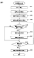
- FIG. 7 is a flowchart of connection-related processing performed by the in-vehicle system
- FIG. 8 is a flowchart of an absorber amount estimation process performed by the authentication ECU
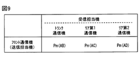
- FIG. 9 is a diagram for describing inter-communication device strength model data.
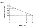
- FIG. 10 is a graph showing the relationship between the amount of attenuation indicating the amount of absorber and the vehicle interior equivalent value
- FIG. 11 is a flowchart of a position determination process performed by the authentication ECU
- FIG. 12 is a diagram for explaining a method of determining the indoor unit intensity representative value and the outdoor unit intensity representative value.
- FIG. 13 is a diagram illustrating a test result of a relationship between the position of the portable terminal and the representative value of the indoor unit strength in an empty state
- FIG. 14 is a diagram illustrating a test result of a relationship between the position of the portable terminal and the indoor unit intensity representative value in the full state
- FIG. 15 is a diagram showing the results of testing the operation of the first comparative configuration.
- FIG. 16 is a diagram showing the results of testing the operation of the second comparative configuration.
- FIG. 17 is a diagram showing the results of testing the operation of the present embodiment
- FIG. 18 is a diagram showing the results of testing the operation of the present embodiment
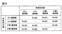
- FIG. 19 is a diagram showing inter-communication device strength model data provided in the authentication ECU of Modification Example 1.
- FIG. 20 is a block diagram illustrating a configuration of a vehicle-mounted system according to Modification Example 8.
- FIG. 18 is a block diagram showing another configuration of the vehicle-mounted system according to Modification Example 8. It is a figure which shows the modification of the attachment position of a communication device outside a vehicle.
- FIG. 1 is a diagram illustrating an example of a schematic configuration of an electronic key system for a vehicle to which a position determination system according to the present disclosure is applied.
- the vehicular electronic key system includes an in-vehicle system 1 mounted on a vehicle Hv and a mobile terminal 2 which is a communication terminal carried by a user of the vehicle Hv.
- Each of the in-vehicle system 1 and the portable terminal 2 is configured to be capable of performing communication (hereinafter referred to as short-range communication) conforming to a predetermined short-range wireless communication standard having a communication range of, for example, at most several tens of meters. .
- a short-range wireless communication standard for example, Bluetooth Low Energy (Bluetooth is a registered trademark), Wi-Fi (registered trademark), ZigBee (registered trademark), and the like can be adopted.
- the in-vehicle system 1 and the mobile terminal 2 of the present embodiment are configured to perform wireless communication in accordance with the Bluetooth Low Energy standard, for example.
- the portable terminal 2 is a device that is associated with the in-vehicle system 1 and functions as an electronic key of the vehicle Hv.
- the mobile terminal 2 may be any device that has the above-described short-range communication function and is portable by a user.
- a smartphone can be used as the mobile terminal 2.
- the portable terminal 2 may be a tablet terminal, a wearable device, a portable music player, a portable game machine, or the like.
- the signal transmitted by the mobile terminal 2 as short-range communication includes transmission source information.
- the transmission source information is, for example, unique identification information (hereinafter, referred to as a terminal ID) assigned to the mobile terminal 2.
- the terminal ID functions as information for identifying the mobile terminal 2 from another communication terminal.
- the mobile terminal 2 notifies a nearby communication terminal having a short-range communication function of its own existence by wirelessly transmitting a communication packet including transmission source information at a predetermined transmission interval (that is, the mobile terminal 2 has a wireless communication packet). Advertise).
- a communication packet that is periodically transmitted for the purpose of advising is referred to as an advertising packet.
- the transmission interval of the advertisement packet may be variable according to the operation status of the mobile terminal 2. For example, when a predetermined application using the short-range communication function is operating in the foreground in the mobile terminal 2, the transmission interval is set to a relatively short time (for example, 50 milliseconds). On the other hand, when the application is not operating in the foreground, the transmission interval is set to a relatively long time (200 milliseconds).
- the mobile terminal 2 only needs to be configured to transmit the advertisement packet at least once during a predetermined time (for example, 200 milliseconds) defined by the vehicular electronic key system.
- the in-vehicle system 1 receives a signal (for example, an advertisement packet) transmitted from the mobile terminal 2 by the short-range communication function, and thereby determines that the mobile terminal 2 exists within a range in which short-range communication with the in-vehicle system 1 is possible. To detect.
- a range in which the in-vehicle system 1 can perform data communication with the mobile terminal 2 by the short-range communication function is also referred to as a communication area.
- the in-vehicle system 1 is configured to detect the presence of the mobile terminal 2 in the communication area by receiving an advertisement packet sequentially transmitted from the mobile terminal 2. Yes, but not limited to this.
- the in-vehicle system 1 sequentially transmits the advertisement packet, and detects that the mobile terminal 2 exists in the communication area based on the establishment of the communication connection (so-called connection) with the mobile terminal 2. May be configured.
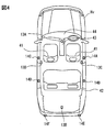
- the vehicle Hv is, for example, a passenger car having a capacity of five passengers.
- the vehicle Hv includes a front seat and a rear seat, and a driver's seat (in other words, a steering wheel) is provided on the right side.
- a space that functions as a luggage compartment is arranged at the rear end of the vehicle interior space of the vehicle Hv.
- the space for the rear seat of the vehicle Hv communicates with the luggage compartment through above the backrest 42 for the rear seat.
- the vehicle Hv may be a vehicle having a structure other than the above-described example.
- the vehicle Hv may be a vehicle provided with a driver's seat on the left side. Further, a vehicle without a rear seat may be used.
- the vehicle Hv may be a vehicle having a luggage compartment independent of the vehicle interior space. The vehicle may have a plurality of rows of rear seats.
- the vehicle Hv may be a lorry such as a truck. Further, the vehicle Hv may be a camper.
- the vehicle Hv may be a vehicle provided for a vehicle rental service (so-called rental car) or a vehicle provided for a car sharing service (so-called share car).
- the shared car also includes a vehicle used for a service that lends a privately owned vehicle to another person at a time when the vehicle administrator is not using the vehicle.
- a service vehicle a vehicle provided with a service
- a person who has contracted to use those services can be the user. That is, a person who has the right to use the vehicle Hv can be the user.
- the body panel is a group of components that provide the appearance of the vehicle Hv.
- the body panel includes a side body panel assembled to the body shell, a roof panel, a rear end panel, a bonnet panel, a door panel, a pillar, and the like.
- a configuration formed by combining various body panels is referred to as a body.
- the body panel of the vehicle Hv reflects radio waves. That is, the vehicle Hv includes a body that blocks the straight propagation of the radio wave.
- the radio wave here refers to a radio wave in a frequency band (here, 2.4 GH band) used for wireless communication between the in-vehicle system 1 and the portable terminal 2.
- the body shell itself may be realized by using a metal member such as a steel plate, or may be formed by using a carbon-based resin.
- the body shell is also made of metal.
- a configuration in which radio waves can be attenuated at a predetermined level corresponds to a configuration in which propagation of radio waves is blocked.
- the target attenuation level may be a value at which a significant difference occurs in the signal strength of radio waves inside and outside the vehicle interior, and is set to, for example, 10 dB.
- the target attenuation level can be set to an arbitrary value of 5 dB or more (for example, 10 dB or 20 dB).
- the vehicle Hv has a roof provided by a roof panel, and includes a plurality of pillars that are members for supporting the roof panel.
- the plurality of pillars are called an A pillar, a B pillar, and a C pillar in order from the front end to the rear end.
- the vehicle Hv includes A pillars, B pillars, and C pillars as pillars.
- the A pillar is a pillar provided in front of the front seat.
- the B pillar is a pillar provided between the front seat and the rear seat.
- the C pillar is a pillar provided diagonally behind the rear seat.
- the vehicle Hv may include a D pillar, which is a fourth pillar from the front, and an E pillar, which is a fifth pillar from the front.
- each pillar is realized by using a metal member such as a high-tensile steel plate.
- the pillar may be made of carbon fiber or resin. Further, it may be realized by combining various materials.
- the right and left sides refer to the right and left sides determined based on the front-rear direction of the vehicle.
- the right B pillar refers to a B pillar arranged on the right side of the vehicle.
- the space in the vehicle interior space that is forward of the vehicle from the backrest 41 of the front seat is referred to as a front area.
- the front area also includes a vehicle interior space above the instrument panel 44.
- a vehicle interior space that is located behind the backrest 41 of the front seat and behind the backrest 42 of the rear seat is referred to as a rear area.
- the interior space located behind the backrest 42 of the rear seat in the vehicle is referred to as a trunk area.
- the trunk area is an area corresponding to a luggage compartment.
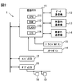
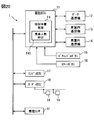
- the in-vehicle system 1 includes an authentication ECU 11, a data communication device 12, a vehicle interior communication device 13, a vehicle exterior communication device 14, a door handle button 15, a start button 16, an engine ECU 17, and a body ECU 18.
- the ECU in the member name is an abbreviation of Electronic Control Unit and means an electronic control unit.
- the authentication ECU 11 roughly determines the position of the mobile terminal 2 in cooperation with the data communication device 12 or the like (in other words, cooperation), and performs vehicle control according to the determination result in cooperation with another ECU.
- the authentication ECU 11 is realized using a computer. That is, the authentication ECU 11 includes a CPU (Central Processing Unit) 111, a RAM 112, a flash memory 113, an I / O 114, and a bus line connecting these components.
- the authentication ECU 11 may be realized using an MPU (Micro Processing Unit) or a GPU (Graphics Processing Unit) instead of the CPU 111.
- the authentication ECU 11 may be realized by combining the CPU 111, an MPU, and a GPU.
- the CPU 111 is an arithmetic processing device that executes various arithmetic processes.
- the RAM 112 is a volatile storage medium, and the flash memory 113 is a rewritable nonvolatile storage medium.
- the I / O 114 is a circuit module that functions as an interface for the authentication ECU 11 to communicate with another device mounted on the vehicle Hv such as the data communication device 12.
- the I / O 114 may be realized using an analog circuit element, an IC, or the like.
- the terminal ID assigned to the portable terminal 2 owned by the user is registered in the flash memory 113.
- the flash memory 113 stores a program for causing the computer to function as the authentication ECU 11 (hereinafter, a position determination program) and the like. Note that the above-described position determination program only needs to be stored in a non-transitive substantive recording medium (non- transitory tangible storage medium). Executing the position determination program by the CPU 111 corresponds to executing a method corresponding to the position determination program.
- the authentication ECU 11 determines whether or not the mobile terminal 2 is present in the vehicle compartment based on the reception intensity of the signal from the mobile terminal 2 (hereinafter, a threshold for determination). Two parameters, an equivalent value Pin and an exterior equivalent value Pout, are stored.
- the vehicle interior equivalent value Pin is a threshold value for determining that the mobile terminal 2 exists in the vehicle interior.
- the out-of-vehicle equivalent value Pout is a threshold value for determining that the mobile terminal 2 exists outside the vehicle compartment.
- the vehicle interior equivalent value Pin corresponds to the vehicle interior determination value
- the vehicle exterior equivalent value Pout corresponds to the vehicle exterior determination value. The technical significance and setting method of the vehicle interior equivalent value Pin and the vehicle exterior equivalent value Pout will be separately described later.
- the flash memory 113 stores inter-communication device strength model data and absorber amount-threshold value map data used in an absorber amount estimation process described later. Details of the authentication ECU 11 will be separately described later.
- the data communication device 12, the vehicle interior communication device 13, and the vehicle exterior communication device 14 are all communication modules (hereinafter referred to as on-vehicle communication devices) mounted on the vehicle Hv for performing short-range communication.
- the data communication device 12 has a role in which the authentication ECU 11 transmits and receives data to and from the mobile terminal 2.
- the in-vehicle communication device 13 and the out-of-vehicle communication device 14 have a role of providing the reception strength of the signal transmitted from the mobile terminal 2 to the authentication ECU 11.
- the data communication device 12, the in-vehicle communication device 13, and the out-of-vehicle communication device 14 are respectively different from each other only in their assigned duties, and can be realized using the in-vehicle communication device 3 having the same configuration.
- the vehicle communication device 3 is communicably connected to the authentication ECU 11 via a dedicated communication line or an in-vehicle network.
- Each vehicle-mounted communication device 3 is set with a unique communication device number.
- the communication device number is information corresponding to a terminal ID for the mobile terminal 2.
- the communication device number functions as information for identifying the plurality of vehicle-mounted communication devices 3.
- FIG. 3 schematically shows the electrical configuration of the vehicle-mounted communication device 3.
- the in-vehicle communication device 3 includes a board 30, an antenna 31, a transmission / reception unit 32, and a communication microcomputer 33.
- the board 30 is, for example, a printed board.
- the board 30 is provided with, for example, electronic components such as an antenna 31 that constitute the on-vehicle communication device 3.
- the antenna 31 is an antenna for transmitting and receiving radio waves in a frequency band (for example, 2.4 GHz band) used for short-range communication.
- a frequency band for example, 2.4 GHz band
- the antenna 31 is a non-directional antenna.
- the antenna 31 may have directivity.
- the antenna 31 is preferably an antenna that is formed in a pattern on the substrate 30 (that is, a pattern antenna) in order to reduce the thickness of the in-vehicle communication device 3.
- the antenna 31 is electrically connected to the transmission / reception unit 32.
- the transmission / reception unit 32 demodulates the signal received by the antenna 31 and provides the signal to the communication microcomputer 33. Further, a signal input from the authentication ECU 11 via the communication microcomputer 33 is modulated, output to the antenna 31, and emitted as a radio wave.
- the transmitting / receiving unit 32 is connected to the communication microcomputer 33 so as to be able to communicate with each other.
- the transmission / reception unit 32 includes a reception strength detection unit 321 that sequentially detects the strength of a signal received by the antenna 31.
- the reception intensity detection unit 321 can be realized by various circuit configurations.
- the reception intensity detected by the reception intensity detection unit 321 is sequentially provided to the communication microcomputer 33 in association with the terminal ID included in the reception data.
- the reception intensity may be expressed, for example, in units of power (dBm).
- reception intensity data data that associates the reception intensity with the terminal ID is referred to as reception intensity data.
- the communication microcomputer 33 is a microcomputer that controls data transfer with the authentication ECU 11.
- the communication microcomputer 33 is realized using an MPU, a RAM, a ROM, and the like.
- the communication microcomputer 33 provides the received data input from the transmission / reception unit 32 to the authentication ECU 11 sequentially or based on a request from the authentication ECU 11. That is, the data received by the transmission / reception unit 32 is provided to the authentication ECU 11 via the communication microcomputer 33.
- the communication microcomputer 33 has a function of authenticating the terminal ID of the mobile terminal 2 and performing a cryptographic communication with the mobile terminal 2 based on a request from the authentication ECU 11.
- the encryption method various methods such as a method defined by Bluetooth can be used.
- the ID authentication method various methods such as a method specified by Bluetooth can be used.
- the communication microcomputer 33 acquires the reception intensity data from the reception intensity detection unit 321, the communication microcomputer 33 accumulates the reception intensity data in a RAM (not shown).
- the reception intensity data sequentially acquired may be sorted in chronological order such that the reception intensity of the latest reception data is at the top, and stored in the RAM. Data that has been stored for a certain period of time is sequentially discarded. That is, the reception intensity data is held in the RAM for a certain period of time.
- the communication microcomputer 33 provides the reception intensity data stored in the RAM based on a request from the authentication ECU 11.
- the reception intensity data provided to the authentication ECU 11 may be deleted from the RAM.
- the reception intensity data output from the transmission / reception unit 32 is temporarily stored in the RAM, and the communication microcomputer 33 provides the reception intensity data stored in the RAM to the authentication ECU 11 based on a request from the authentication ECU 11.
- the present invention is not limited to this. A configuration in which the reception intensity data is sequentially provided to the authentication ECU 11 may be employed.
- the data communication device 12 is the on-board communication device 3 which has already executed the key exchange protocol (so-called pairing) with the mobile terminal 2 based on the operation of the user or the like.
- Information on the mobile terminal 2 acquired by pairing (hereinafter, terminal information) is stored in a nonvolatile memory included in the communication microcomputer 33.
- the terminal information is, for example, a key exchanged by pairing, a terminal ID, or the like. Storing the exchanged keys is also called bonding.
- the vehicle Hv is used by a plurality of users, the terminal information of the mobile terminal 2 owned by each user is stored.
- the data communication device 12 Upon receiving the advertisement packet from the mobile terminal 2, the data communication device 12 automatically establishes a communication connection with the mobile terminal 2 using the stored terminal information. Then, the authentication ECU 11 transmits and receives data to and from the mobile terminal 2. When the data communication device 12 establishes the communication connection with the mobile terminal 2, the data communication device 12 provides the authentication ECU 11 with the terminal ID of the mobile terminal 2 that is connected with the communication.
- the frequency hopping method is a communication method in which channels used for communication are sequentially switched over time.
- data communication is performed by a frequency hopping / spread spectrum (FHSS).
- FHSS frequency hopping / spread spectrum
- Bluetooth LE In Bluetooth Low Energy (hereinafter referred to as Bluetooth LE), 40 channels from 0 to 39 are prepared, of which 37 channels from 0 to 36 can be used for data communication.
- the three channels 37 to 39 are channels used for transmitting advertisement packets.
- the data communication device 12 transmits and receives data to and from the mobile terminal 2 while sequentially changing the 37 channels while the communication connection with the mobile terminal 2 is established. At that time, the data communication device 12 sequentially provides the authentication ECU 11 with information indicating a channel used for communication with the mobile terminal 2 (hereinafter, channel information).
- the channel information may be a specific channel number or a parameter (so-called hopIncrement) indicating a transition rule of a used channel. HopIncrement is a number from 5 to 16 that is randomly determined at the time of communication connection.
- the channel information includes the current channel number and HopIncrement.
- the data communication device 12 is arranged at a position where the vicinity of a door inside and outside the vehicle compartment can be seen.
- the position where the vicinity of the door inside and outside the vehicle compartment can be seen is, for example, a ceiling portion in the vehicle interior. If the vehicle Hv includes a pillar made of resin, the pillar portion also corresponds to a position where the vicinity of a door inside and outside the vehicle compartment can be seen.
- the data communication device 12 of the present embodiment is disposed near the center of the ceiling in the vehicle interior.
- the line of sight for a certain in-vehicle communication device 3 is an area where a signal transmitted from the in-vehicle communication device 3 can directly reach. Since the propagation path of the wireless signal is reversible, the line of sight for a certain in-vehicle communication device 3 means that the signal transmitted from the mobile terminal 2 is directly transmitted by the in-vehicle communication device 3. This corresponds to a receivable area.
- a non-line of sight for a certain in-vehicle communication device 3 is an area where a signal transmitted from the in-vehicle communication device 3 does not directly reach. Since the propagation path of the wireless signal is reversible, it is out of sight for a certain in-vehicle communication device 3, in other words, the in-vehicle communication device 3 directly receives the signal transmitted from the mobile terminal 2. It corresponds to the area where it cannot be done. Note that, even when the mobile terminal 2 is out of the line of sight of the on-vehicle communication device 3, the signal transmitted from the mobile terminal 2 can reach out of the line of sight by being reflected by various structures. That is, even when the mobile terminal 2 exists outside the line of sight of the data communication device 12, the mobile terminal 2 and the data communication device 12 can perform wireless communication by reflection on a structure or the like.
- the number of the data communication devices 12 provided in the vehicle Hv is one, but it is not limited to this.
- a plurality of in-vehicle communication devices 3 as the data communication device 12 may be provided in the vehicle Hv.
- a part of the in-vehicle communication device 13 and a part of the out-of-vehicle communication device 14 described later may be set to function as the data communication device 12.
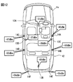
- the in-vehicle communication device 13 is the in-vehicle communication device 3 arranged in the vehicle interior. At least one vehicle interior communication device 13 is provided in the vehicle interior. Although only one in-vehicle communication device 13 is shown in FIG. 2 for convenience, the in-vehicle system 1 may include a plurality of in-vehicle communication devices 13. As shown in FIG. 4, the in-vehicle system 1 of the present embodiment includes a front communication device 13A, a trunk communication device 13B, a rear first communication device 13C, and a rear second communication device 13D as the vehicle interior communication device 13. In addition, since the data communication device 12 described above is also arranged in the vehicle interior in the present embodiment, the data communication device 12 can also be operated as one of the vehicle interior communication devices 13.
- FIG. 4 is a conceptual top view of the vehicle Hv, and shows the roof part in a transparent manner in order to explain the installation positions of various vehicle interior communication devices 13 and various vehicle exterior communication devices 14. . Further, the installation position of each of the in-vehicle communication devices 13 described below can be appropriately changed. Further, the number of the in-vehicle communication devices 13 included in the in-vehicle system 1 can be changed as appropriate. The number of in-vehicle communication devices 13 may be less than four, such as one, two, or three. The number of in-vehicle communication devices 13 may be five or more.
- the front communication device 13A is a vehicle interior communication device 13 for setting a front area in the vehicle interior as a strong electric field area.
- the strong electric field area here is an area in which a signal transmitted from the in-vehicle communication device 3 propagates while maintaining an intensity equal to or higher than a predetermined threshold (hereinafter, a strong electric field threshold).
- the strong electric field threshold is set to a sufficiently strong level as a signal for short-range communication.
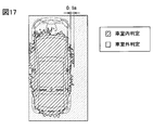
- the strong electric field threshold is ⁇ 35 dBm ( ⁇ 0.316 ⁇ W).
- the strong electric field area is, according to another viewpoint, an area where the reception strength of the signal transmitted from the portable terminal 2 in the vehicle-mounted communication device 3 is equal to or higher than the strong electric field threshold. is there.
- the area within 0.8 m from the vehicle-mounted communication device 3 tends to be a strong electric field area.
- the front communication device 13A is provided at a position where the outside of the cabin is out of sight.
- the front communicator 13A is arranged, for example, near a boundary between the center console 43 and the instrument panel 44.
- the installation position of the front communication device 13A is not limited to this. For example, it may be arranged at the foot of the driver's seat or on the side of the door for the driver's seat on the vehicle interior side.
- the front communicator 13A may be arranged at a suitably designed position around the front seat so that the front area becomes a strong electric field area.
- the trunk communication device 13B is a vehicle interior communication device 13 for setting the trunk area to a strong electric field area. It is preferable that the trunk communication device 13B is also arranged at a position where the outside of the vehicle compartment tends to be out of sight. For example, the trunk communication device 13B is disposed on the floor of the luggage compartment.
- the rear first communication device 13C and the rear second communication device 13D are the vehicle interior communication devices 13 for mainly setting the rear area as a strong electric field area. It is preferable that the rear first communication device 13C and the rear second communication device 13D are also arranged at positions where the outside of the vehicle compartment is likely to be out of sight.
- the rear first communication device 13C is disposed, for example, on the indoor side surface of the right B pillar.
- the rear first communication device 13C may be installed on a surface of the door provided on the right side of the vehicle Hv as a door for a rear seat (hereinafter, a rear right door) on the vehicle interior side.
- the rear first communication device 13C may be disposed on the right side of the floor of the rear seat, or may be buried in the right side of the seating surface of the rear seat.
- the rear second communication device 13D is disposed, for example, on the indoor side surface of the left B pillar.
- the rear second communication device 13D may be installed on a surface of the door provided on the left side of the vehicle Hv as a door for a rear seat (hereinafter, a rear left door) on the vehicle interior side.
- the rear second communication device 13D may be arranged on the left side of the floor of the rear seat, or may be buried in the left side of the seating surface of the rear seat.
- the rear first communication device 13C and the rear second communication device 13D may be arranged near the lower end of the rear seat side surface of the backrest 41.
- the in-vehicle system 1 includes two in-vehicle communicators 13 each on the left and right for setting the rear area as a strong electric field area, but the arrangement of the in-vehicle communicators 13 is not limited to this. Absent.
- the in-vehicle system 1 may be configured such that the rear area is a strong electric field area by one vehicle interior communication device 13.
- the in-vehicle communication device 13 for the rear area may be buried, for example, near the center of the seating surface of the rear seat in the vehicle width direction.
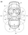
- FIG. 5 conceptually shows a strong electric field area provided by each vehicle-mounted communication device 3 in the configuration shown in FIG.
- the solid circle in FIG. 5 indicates a strong electric field area provided by the in-vehicle communication device 13.
- a broken arc represents a strong electric field area provided by the external communication device 14 described below.
- the hatched area of the dot pattern conceptually represents a leak area formed by the in-vehicle communication device 13.
- the leak area formed by the in-vehicle communication device 13 is a region where the strong electric field area provided by the in-vehicle communication device 13 protrudes outside the cabin. In other words, it is an area where the signal transmitted by the in-vehicle communication device 13 reaches the outside of the cabin while maintaining the strength equal to or higher than the predetermined strong electric field threshold value.
- the in-vehicle communicator 13 is disposed for each area divided by the in-vehicle structure capable of obstructing the propagation of radio waves having a frequency used for short-range communication so that the area is set as a strong electric field area.
- the vehicle interior structures that can obstruct the propagation of radio waves of frequencies used for short-range communication are the backrest 41 of the front seat and the backrest 42 of the rear seat.
- the areas divided by the vehicle interior structure are a front area, a rear area, and a trunk area.
- the vehicle exterior communication device 14 is the vehicle-mounted communication device 3 arranged on the outer surface of the vehicle Hv.
- the outer surface portion here is a body portion of the vehicle Hv that is in contact with the vehicle exterior space, and includes a side surface portion, a rear surface portion, and a front surface portion of the vehicle Hv.
- FIG. 2 only one outside-vehicle communication device 14 is illustrated for convenience, but the in-vehicle system 1 may include a plurality of outside-vehicle communication devices 14. At least one of the external communication devices 14 is disposed on, for example, an outer surface of a driver seat door, a roof portion of the vehicle Hv, a hood, a pillar, or the like such that a predetermined area outside the vehicle interior is a strong electric field area. .
- the in-vehicle system 1 of the present embodiment includes a right side first communicator 14A, a right side second communicator 14B, a left side first communicator 14C, and a left side second communicator 14 as the exterior communicator 14.
- a communication device 14D, a back first communication device 14E, and a back second communication device 14F are provided.
- the number of external communication devices 14 included in the in-vehicle system 1 can be changed as appropriate.
- the number of out-of-vehicle communication devices 14 may be six or less, such as two, three, four, or eight or more.
- the right-side first communication device 14A is an outside-cabin communication device 14 for setting a periphery of a front seat door (hereinafter referred to as a front right door) provided on the right side of the vehicle Hv as a strong electric field area.
- a front right door since the driver's seat is arranged on the right side of the vehicle Hv, the front right door corresponds to the driver's seat door.
- the periphery of the front right door is an area within a predetermined distance (for example, 1 m) from a door handle arranged on the outer surface of the front right door.
- the right side first communication device 14A is arranged, for example, near the outside door handle of the front seat door. The vicinity of the door handle includes the inside of the door handle.
- the right side first communication device 14A may be arranged near the right front wheel. Further, the first communication device 14A on the right side may be arranged in a locker portion below the front right door, a portion of the roof of the vehicle Hv where the upper end of the front right door contacts, or the like.
- the second communicator 14B on the right side is the external communicator 14 for setting the periphery of the rear right door as a strong electric field area.
- the area around the rear right door is an area within a predetermined distance (for example, 1 m) from a door handle arranged on the outer surface of the rear right door.
- the right side second communication device 14B is arranged, for example, near the outside door handle of the rear seat door. The vicinity of the door handle includes the inside of the door handle.
- the right side second communication device 14B may be arranged near the right rear wheel. Further, the right-side second communication device 14B may be disposed in a locker portion below the rear right door, or in a portion of the roof of the vehicle Hv where the upper end of the rear right door contacts.
- the left-side first communicator 14C and the left-side second communicator 14D are the outside-cabin communicators 14 paired with the right-side first communicator 14A and the right-side second communicator 14B, respectively. .
- the left side first communication device 14C is disposed at a position opposite to the right side first communication device 14A on the left side surface portion of the vehicle Hv.
- the left side second communication device 14D is also arranged at a position opposite to the right side second communication device 14B on the left side surface portion of the vehicle Hv.
- the rear first communication device 14E is the vehicle exterior communication device 14 arranged near the right corner at the rear end of the vehicle.
- the rear second communication device 14F is the vehicle exterior communication device 14 arranged near the left corner at the rear end of the vehicle.
- the first rear communication device 14E and the second rear communication device 14F are external communication devices 14 for forming a strong electric field area behind the vehicle (that is, for the rear of the vehicle).
- the structure provided with two exterior communication devices 14 for a vehicle rear is proposed, it is not limited to this.
- the number of the outside communication device 14 for the rear of the vehicle may be one.
- the vehicle exterior communication device 14 for the rear of the vehicle is disposed at a central portion in a vehicle width direction such as a trunk door or a rear bumper.
- the vehicle exterior communication device 14 for the rear of the vehicle may be provided near a door handle of a trunk door or near a license plate.
- each external communication device 14 is not limited to the above-described embodiment.
- the external communication device 14 may be disposed on the outer surface of the vehicle Hv so as to cover the leakage region formed by the internal communication device 13 with the strong electric field area.
- the various exterior communication devices 14 (for example, the right side second communication device 14B) disposed on the left and right side surfaces of the vehicle Hv do not overlap with the vehicle interior communication device 13 (for example, the rear first communication device 13C) in side view. Position.
- the vehicle exterior communication device 14 is provided near the surface of the metal body panel. In other words, it is preferable that a metal plate be disposed on the back surface of the external communication device 14.
- the rear surface of the outside communication device 14 is a direction in which the inside of the vehicle compartment exists when viewed from the outside communication device 14. According to the aspect in which the exterior communication device 14 is disposed on the surface of the metal body panel, the body panel functions as a reflector, and the directivity center of the exterior vehicle communication device 14 can be directed to the outside of the vehicle compartment. .
- the body panel functions as a reflector, the interior of the vehicle is out of sight for the external communication device 14, and radio waves of the external communication device 14 enter the vehicle interior or radio waves from the portable terminal 2 existing in the vehicle interior. Can be reduced by the external communication device 14.
- various body panels are made of metal. Therefore, according to the aspect in which the exterior communication device 14 is installed on a door panel or the like, the interior of the vehicle compartment is out of sight for various exterior communication devices 14, and the center of directivity is directed toward the exterior of the vehicle compartment.
- the outside direction of the vehicle is a direction parallel to the vehicle horizontal plane and going from the center of the vehicle to the outside of the vehicle.
- the vehicle horizontal plane is a plane orthogonal to the height direction of the vehicle Hv.
- the gain in the external direction of the vehicle can be changed according to the distance between the metal body and the antenna 31. This is because the phase difference between the reflected wave and the direct wave at the metal body changes according to the distance between the metal body and the antenna 31, and the radio waves are strengthened or weakened. The point where the radio waves are weakened may occur every half wavelength.
- the various exterior communication devices 14 are arranged so that the distance between the built-in antenna 31 and the metal body existing on the back surface of the exterior communication device 14 is about 1.5 cm. .
- Both the in-vehicle communication device 13 and the out-of-vehicle communication device 14 are mainly configured to report the reception strength of the signal from the mobile terminal 2 to the authentication ECU 11. Therefore, hereinafter, the various in-vehicle communication devices 13 and the out-of-vehicle communication devices 14 are also described as intensity observing devices. Each intensity observer provides the received intensity of the signal transmitted from the mobile terminal 2 to the authentication ECU 11. As described above, a part or the whole of the intensity observation device may play a role as the data communication device 12.
- the door handle button 15 is a button for the user to unlock and lock the door of the vehicle Hv. What is necessary is just to provide in each door handle of the vehicle Hv.
- the door handle button 15 When the door handle button 15 is pressed by the user, the door handle button 15 outputs an electric signal to that effect to the authentication ECU 11.
- the door handle button 15 corresponds to a configuration in which the authentication ECU 11 receives a user's unlocking instruction and locking instruction.
- a touch sensor may be employed as a configuration for receiving at least one of the unlocking instruction and the locking instruction from the user.
- the touch sensor is a device that detects that the user is touching the door handle.
- a touch sensor as a configuration for receiving a user's unlocking instruction or locking instruction may be provided on each door handle of the vehicle Hv.
- the start button 16 is a push switch for a user to start a driving source (for example, an engine). When a push operation is performed by the user, the start button 16 outputs an electric signal indicating that to the authentication ECU 11.
- the vehicle Hv is a vehicle provided with an engine as a power source, but is not limited to this.
- the vehicle Hv may be an electric vehicle or a hybrid vehicle.
- the start button 16 is a switch for starting the drive motor.
- the engine ECU 17 controls the operation of the engine mounted on the vehicle Hv. For example, when the engine ECU 17 obtains a start instruction signal for instructing start of the engine from the authentication ECU 11, the engine ECU 17 starts the engine.
- the body ECU 18 is an ECU that controls the vehicle-mounted actuator 19 based on a request from the authentication ECU 11.
- the body ECU 18 is communicably connected to various vehicle-mounted actuators 19 and various vehicle-mounted sensors.
- the on-vehicle actuator 19 here is, for example, a door lock motor constituting a lock mechanism of each door, an actuator for adjusting a seat position (hereinafter, a seat actuator), and the like.
- the on-vehicle sensor here is a courtesy switch or the like arranged for each door.
- the courtesy switch is a sensor that detects opening and closing of a door.
- the body ECU 18 locks and unlocks each door by outputting a predetermined control signal to a door lock motor provided to each door of the vehicle Hv based on a request from the authentication ECU 11, for example.
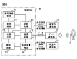
- the authentication ECU 11 provides functions corresponding to various functional blocks illustrated in FIG. 6 by executing the position determination program. That is, the authentication ECU 11 includes, as functional blocks, a vehicle information acquisition unit F1, a communication processing unit F2, an authentication processing unit F3, an absorber quantity estimation unit F4, a threshold adjustment unit F5, a position determination unit F6, and a vehicle control unit F7. I have.
- the functions executed by the authentication ECU 11 may be realized as hardware using a logic circuit or the like.
- the aspect realized as hardware includes an aspect realized using one or a plurality of ICs.
- some or all of the functional blocks included in the authentication ECU 11 may be realized by a combination of execution of software by the CPU 111 and an electronic circuit.
- the vehicle information acquisition unit F1 acquires various information indicating the state of the vehicle Hv (hereinafter, vehicle information) from a sensor, an ECU (for example, the body ECU 18), a switch, and the like mounted on the vehicle Hv.
- vehicle information includes, for example, an open / closed state of a door, a locked / unlocked state of each door, whether or not a door handle button 15 is pressed, and whether or not a start button 16 is pressed.
- the vehicle information acquisition unit F1 specifies the current state of the vehicle Hv based on the various information described above. For example, the vehicle information acquisition unit F1 determines that the vehicle Hv is parked when the engine is off and all doors are locked. Of course, the conditions for determining that the vehicle Hv is parked may be appropriately designed, and various determination conditions and the like can be applied.
- acquiring the information indicating the locked / unlocked state of each door is equivalent to determining the locked / unlocked state of each door and detecting the locking / unlocking operation of the door by the user.
- Acquiring an electric signal from the door handle button 15 or the start button 16 corresponds to detecting a user operation on these buttons. That is, the vehicle information acquisition unit F1 corresponds to a configuration that detects a user operation on the vehicle Hv such as opening and closing of the door, pressing of the door handle button 15, and pressing of the start button 16.
- the vehicle information thereafter includes a user operation on the vehicle Hv.
- the vehicle information also includes a shift position detected by a shift position sensor (not shown), a detection result of a brake sensor that detects whether or not a brake pedal is depressed, and the like.
- the operating state of the parking brake can also be included in the vehicle information.
- the communication processing unit F2 is configured to transmit and receive data to and from the mobile terminal 2 in cooperation with the data communication device 12. For example, the communication processing unit F2 generates data addressed to the mobile terminal 2 and outputs the data to the data communication device 12. Thereby, a signal corresponding to desired data is transmitted as a radio wave. Further, the communication processing unit F2 receives data from the portable terminal 2 received by the data communication device 12. In a more preferred embodiment, the wireless communication between the authentication ECU 11 and the mobile terminal 2 is configured to be performed in an encrypted manner. The authentication ECU 11 as the communication processing unit F2 acquires channel information from the data communication device 12. Thereby, the authentication ECU 11 specifies a channel used by the data communication device 12 for communication with the mobile terminal 2.
- the authentication ECU 11 acquires, from the data communication device 12, the terminal ID of the portable terminal 2 to which the data communication device 12 is connected for communication. According to such a configuration, even if the vehicle Hv is a vehicle shared by a plurality of users, the authentication ECU 11 determines the vicinity of the vehicle Hv based on the terminal ID of the mobile terminal 2 to which the data communication device 12 is connected. The user who exists in can be specified.
- the communication processing unit F2 distributes the channel information and the terminal ID acquired from the data communication device 12 to each intensity monitoring device as reference information. Based on the channel information indicated in the reference information, each intensity observer can recognize which of the many channels provided by the Bluetooth standard should be received to receive a signal from the portable terminal 2. In addition, even when signals are received from a plurality of devices, the intensity observer uses the terminal ID indicated in the reference information to determine which device should receive the signal reception intensity from the authentication ECU 11. It can be specified.
- the authentication processing unit F3 performs a process of authenticating the portable terminal 2 in cooperation with the data communication device 12 (hereinafter, an authentication process).
- Short-range communication for authentication is performed by the data communication device 12 after being encrypted. That is, the authentication process is performed by the encrypted communication.
- the authentication process itself may be performed using various methods such as a challenge-response method. Here, the detailed description is omitted. It is assumed that data (for example, an encryption key) necessary for the authentication processing is stored in each of the mobile terminal 2 and the authentication ECU 11.
- the timing at which the authentication processing unit F3 performs the authentication processing may be, for example, the timing at which the communication connection between the data communication device 12 and the mobile terminal 2 is established.
- the authentication processing unit F3 may be configured to execute the authentication processing at a predetermined cycle while the data communication device 12 and the mobile terminal 2 are connected for communication. Further, a configuration may be adopted in which, for example, when a user presses the start button 16, a predetermined user operation on the vehicle Hv is used as a trigger to perform encrypted communication for authentication processing.
- the authentication ECU 11 and the mobile terminal 2 are configured to encrypt and execute data communication for authentication and the like for improving security, but the present invention is not limited to this.
- the authentication ECU 11 and the mobile terminal 2 may be configured to perform data communication for authentication or the like without encryption.
- the authentication ECU 11 may be configured to determine that the authentication of the mobile terminal 2 is successful based on the establishment of the communication connection between the data communication device 12 and the mobile terminal 2.
- the absorber amount estimating unit F4 determines whether a radio wave absorber, which is an object that can absorb a radio wave of short-range communication, based on a communication state (for example, the strength of a received signal) between the in-vehicle communication devices 3 arranged in the vehicle compartment. This is a configuration for estimating the amount existing in the vehicle interior.
- the threshold adjuster F5 adjusts the vehicle interior equivalent value Pin based on the estimation result of the absorber quantity estimator F4. The operations of the absorber amount estimating unit F4 and the threshold adjusting unit F5 will be separately described later.
- the radio wave absorber here is, for example, a person.
- foods such as meat and water and small animals such as pets also correspond to the radio wave absorber. This is because these objects contain moisture and can absorb radio waves of 2.4 GHz.
- a child seat can also be a radio wave absorber.
- the radio wave absorber here is an element whose amount and position existing in the vehicle compartment can be dynamically changed (for example, each time the vehicle travels).
- the radio wave absorber may be an object having a property of absorbing radio waves for short-range communication, which can be brought into the cabin in a normal use of the vehicle Hv.
- the normal use of the vehicle Hv refers to, for example, shopping, excursions, commuting, transportation, and the like.
- the radio wave absorber here refers to an occupant or the like, and is not limited to an object (for example, a radio wave absorption sheet) manufactured for the purpose of absorbing radio waves. If the radio wave absorbing sheet is brought into the passenger compartment by the user, the radio wave absorbing sheet may also correspond to the radio wave absorber.
- the position determination unit F6 is configured to determine whether the mobile terminal 2 is present in the vehicle compartment based on the reception strength of the signal from the mobile terminal 2 provided from each of the plurality of intensity observers. Since the mobile terminal 2 is basically carried by the user, determining the position of the mobile terminal 2 corresponds to determining the position of the user. As a preparation process for determining the position of the mobile terminal 2, the position determination unit F6 sequentially obtains and obtains the reception strength of the signal from the mobile terminal 2 from a plurality of intensity observers included in the in-vehicle system 1. The reception intensity is stored in the RAM 112 separately for each acquisition source.
- the position determination unit F6 determines whether the mobile terminal 2 is present in the vehicle interior based on the reception intensity for each intensity observation device stored in the RAM 112 and various determination thresholds registered in the flash memory 113. Is determined.
- the specific operation of the position determination unit F6, that is, the method by which the position determination unit F6 determines the position of the portable terminal 2 based on the reception intensity for each intensity observer will be described later in detail.
- the determination result of the position determination unit F6 is referred to by the vehicle control unit F7.
- the vehicle control unit F7 performs vehicle control according to the position of the mobile terminal 2 (in other words, the user) and the state of the vehicle Hv by the body ECU 18 or the like. It is configured to execute in cooperation with.
- the state of the vehicle Hv is determined by the vehicle information acquisition unit F1.
- the position of the mobile terminal 2 is determined by the position determination unit F6.
- the vehicle control unit F7 cooperates with the body ECU 18 to open the door. Unlock the lock mechanism.
- the position determination unit F6 determines that the mobile terminal 2 is present in the vehicle interior and detects that the start button 16 has been pressed by the user, the engine is started in cooperation with the engine ECU 17. Let it.
- the vehicle control unit F7 is basically configured to execute vehicle control according to the position of the user and the state of the vehicle Hv, triggered by a user operation on the vehicle Hv. However, some of the vehicle controls that can be executed by the vehicle control unit F7 may be automatically executed according to the position of the user without requiring the user to operate the vehicle Hv.
- connection-related processing is a process related to establishment of a communication connection between the in-vehicle system 1 and the mobile terminal 2.
- the connection-related processing shown in FIG. 7 may be started, for example, when the data communication device 12 receives an advertisement packet from the mobile terminal 2.
- the standby state is a state in which a signal (for example, an advertisement packet) from the mobile terminal 2 can be received.
- the data communication device 12 establishes a communication connection (in other words, a connection) with the portable terminal 2, and proceeds to S102.
- the data communication device 12 provides the terminal ID of the mobile terminal 2 connected with the data communication device 12 to the authentication ECU 11.
- the authentication ECU 11 outputs a predetermined control signal to the intensity monitoring device when the data communication device 12 is in the sleep mode when the communication connection with the portable terminal 2 is established. Then, it is shifted to the standby state.
- the sleep mode is, for example, a state in which the signal receiving function is stopped.
- the sleep mode includes a state in which the power is off.
- the data communication device 12 periodically performs the encryption communication based on the instruction from the authentication ECU 11.
- the content of the data exchanged at this time may be anything as long as it requests the portable terminal 2 to return a response signal.
- Data for authenticating the mobile terminal 2 such as a challenge code may be used.
- the authentication ECU 11 can confirm that the mobile terminal 2 exists in the communication area.
- the data communication device 12 and the authentication ECU 11 cooperate to start sharing reference information. Specifically, the data communication device 12 sequentially provides the authentication ECU 11 with the terminal ID and the channel information of the mobile terminal 2 connected for communication. In addition, the authentication ECU 11 sequentially distributes the channel information and the terminal ID provided from the data communication device 12 to each strength observation device as reference information.
- each intensity observer starts observing the reception intensity of the signal from the portable terminal 2 using the reference information provided from the authentication ECU 11. That is, the intensity observer sets, as a reception target, a channel having a number indicated in the channel information among a number of channels provided in the Bluetooth standard. In addition, the intensity observer sequentially changes the channel to be received according to the channel information provided from the authentication ECU 11.
- the various in-vehicle communication devices 3 included in the in-vehicle system 1 receive the signal from the mobile terminal 2. Can be detected.
- S105 it is determined whether or not the intensity observer has received a signal including the terminal ID indicated in the reference information. If a signal including the terminal ID indicated in the reference information has been received, the process proceeds to S106.
- S106 the reception strength of the reception signal is reported to the authentication ECU 11. In other words, in S105 to S106, various intensity observers report to the authentication ECU 11 the reception intensity of the signal including the terminal ID indicated in the reference information among the signals received on the channel indicated in the channel information. If a signal from the mobile terminal 2 has not been received for a certain period of time in S105, S108 may be executed.
- the authentication ECU 11 executes a process of storing the reception intensity provided from each intensity monitoring device in the RAM 112 separately for each intensity monitoring device as a providing source, and proceeds to S108.
- the authentication ECU 11 and the data communication device 12 cooperate to determine whether the communication connection with the mobile terminal 2 has been terminated.
- the case where the communication connection with the mobile terminal 2 is terminated is, for example, a case where the data communication device 12 cannot receive a signal from the mobile terminal 2. If the communication connection with the mobile terminal 2 has been completed, a positive determination is made in S108 and S109 is executed. On the other hand, if the communication connection with the mobile terminal 2 is still maintained, the process returns to S105.
- the authentication ECU 11 outputs a predetermined control signal to the intensity monitoring device, and terminates the process of observing the reception intensity of the signal from the mobile terminal 2. For example, the authentication ECU 11 shifts, for example, the intensity observer to the suspension mode. When the process in S109 is completed, this flow ends.
- the absorber amount estimation process is a process for determining the amount of the radio wave absorber existing in the vehicle interior (that is, the absorber amount). This absorber amount estimation process is performed, for example, at a predetermined absorber amount estimation period in a state where the communication connection between the data communication device 12 and the mobile terminal 2 is established.
- the absorber amount estimation cycle is, for example, one second. Of course, the absorber amount estimation cycle may be 400 milliseconds.
- the absorber amount estimating process is performed at a predetermined time, such as when a communication connection between the data communication device 12 and the portable terminal 2 is established, when an open door is closed, or when the start button 16 is pressed. May be configured to be triggered by the occurrence of the above event.
- the absorber amount estimating process may be configured to execute a predetermined vehicle operation for using the vehicle Hv by the user as a trigger, such as opening and closing a door, pressing a start button 16, and operating a shift lever.
- the absorber amount estimation processing of the present embodiment includes S201 to S205 as an example.
- the absorber amount estimating unit F4 sets a role for each vehicle interior communication device 13 related to wireless communication for estimating the absorber amount. Specifically, any one of the plurality of in-vehicle communication devices 13 is set as the transmission device, and at least one of the other in-vehicle communication devices 13 is set as the reception device.
- the transmitting device is a communication device having a role of transmitting a radio signal
- the receiving device is a communication device having a role of receiving a signal transmitted by the transmitting device and reporting the reception strength to the authentication ECU 11.
- the transmitting device and the receiving device may be selected from the in-vehicle communication device 13 installed in the vehicle cabin.
- the front communication device 13A is set as the transmission device, and each of the other three vehicle interior communication devices 13 is set as the reception device. That is, the trunk communication device 13B, the first rear communication device 13C, and the second rear communication device 13D operate as receiving devices.
- the transmission device may be the trunk communication device 13B, or may be another vehicle communication device 13. Also, it is sufficient that at least one receiver is in charge, and it is not always necessary to operate all the in-vehicle communication devices 13 other than the transmitter in charge as receivers.
- the absorber quantity estimating unit F4 transmits a predetermined wireless signal including the communication device number to the front communication device 13A as a transmission device in cooperation with the communication processing unit F2.
- the signal transmitted by the front communication device 13A serving as the transmission device can be, for example, an advertisement signal.
- the transmission device transmits a wireless signal based on an instruction from the authentication ECU 11, but is not limited thereto.
- the transmission device may be configured to spontaneously transmit the advertisement signal periodically.
- the in-vehicle communication device 13 operates as the transmission device is controlled by an instruction from the authentication ECU 11 (specifically, the absorber amount estimation unit F4).
- a predetermined radio signal including the communication device number transmitted by the transmission device corresponds to the indoor unit transmission signal. Note that the communication device number of the device in charge of transmission corresponds to the transmission source information.
- each of the in-vehicle communication devices 13 serving as the receiving device reports the reception intensity of the wireless signal (for example, the advertising signal) transmitted from the transmitting device to the authentication ECU 11.
- Po (AB) indicates the reception strength of the signal from the front communication device 13A, which is observed in the trunk communication device 13B, the rear first communication device 13C, and the rear second communication device 13D in the present absorber amount estimation processing, in order.
- “P” of “Po” indicates power, and “o” is used to mean an observed value.
- the observation value Po for each of the in-vehicle communication devices 13 is not a result of one reception by the in-vehicle communication device 13 but a plurality of (specifically, for the most recent M times) within the latest predetermined time. ) Make the average value of the reception strength. According to such a configuration, it is possible to reduce the influence of the instantaneous fluctuation of the reception intensity.
- the observation value Po may be a median value or a maximum value of the most recent M reception intensities. Further, the observation value Po may be an average value of the reception intensity obtained by removing the maximum value and the minimum value from the latest M reception intensity.
- M is 5, for example.
- the value of M can be 3 or 10, or the like.
- M may be 1.
- the observed value Po calculated based on the reception intensity of the latest M times in the vehicle interior communication device 13 corresponds to the receiver individual intensity representative value.
- the various in-vehicle communication devices 3 are configured to perform wireless communication in accordance with the Bluetooth standard. That is, the frequency used for wireless communication is sequentially changed by frequency hopping.
- Such a configuration corresponds to an example of a configuration in which the transmission unit transmits a wireless signal as an indoor unit transmission signal using a plurality of frequencies.
- the receiver in charge of the present embodiment is configured to sequentially detect the reception strength of the indoor unit transmission signal sequentially transmitted at a plurality of frequencies.
- the absorber quantity estimating unit F4 that calculates the observation value Po based on the reception intensity at a plurality of time points corresponds to a configuration that calculates the observation value Po as a receiver individual intensity representative value using the reception intensity for each frequency.
- the vehicle exists in the vehicle compartment.
- the attenuation amount S representing the amount of the radio wave absorbed by the radio wave absorber is calculated.
- the inter-communication device strength model data indicates the assumed value of the signal reception strength from the transmission device in each reception device in a state in which there is no object other than the configuration provided in the vehicle interior (hereinafter, an empty vehicle state). It is the data shown.
- the inter-communication device strength model data of the present embodiment indicates an assumed value of the reception strength at each reception device with respect to the transmission signal of the transmission device in the empty state.
- FIG. 9 conceptually shows the structure of the vehicle-mounted device strength model data of the present embodiment.
- Pm (AB) in the figure represents an assumed value of the reception strength at the trunk communication device 13B with respect to the signal transmitted from the front communication device 13A as the transmission device.
- Pm (AC) and Pm (AD) also respectively represent assumed values of the reception strength at the rear first communicator 13C and the rear second communicator 13D with respect to the signal transmitted from the front communicator 13A as the responsible device for transmission.
- “m” in “Pm” is used to mean an assumed value (in other words, a model value).
- the expected value of the reception intensity may be determined by the manufacturer (eg, designer) of the position estimation system 100.
- the assumed value of the reception strength at a certain vehicle interior communication device 13 is the average value of a plurality of actually measured values obtained by causing the front communication device 13A to perform signal transmission a plurality of times in a state where the vehicle interior is set to an empty state. can do. If the assumed values Pm (AB), Pm (AC), and Pm (AD) are not distinguished from each other, they are described as assumed values Pm.
- the assumed value Pm corresponds to the assumed strength value.
- a state where the vehicle interior is set to an empty state corresponds to a model environment.
- the flash memory 113 storing the inter-communication device strength model data corresponds to a strength model storage unit.
- the configuration provided in the vehicle cabin refers to, for example, a seat, a steering wheel, and the like.
- the empty state corresponds to a state in which nothing is brought into the vehicle interior by a user or the like, and no one is in the vehicle.
- the empty vehicle state corresponds to, for example, a vehicle interior environment at the time of factory shipment / delivery.
- the reception intensity of the signal transmitted from the transmitting device at each receiving device may be affected by the position of the seat such as the driver's seat.
- the in-vehicle device strength model data of the present embodiment is obtained by causing the transmitting device to transmit a signal a plurality of times in an empty state, and in a state where the seat position is set to a predetermined default position. It is assumed that it has been determined based on the reception intensity observation value of the receiver in charge.
- the absorber amount estimating unit F4 calculates the estimated value of the reception intensity registered as the in-vehicle unit intensity model data and the reception intensity observed in each of the vehicle interior communication devices 13 in the current absorber amount estimation process.
- a model difference value For example, a value obtained by subtracting the reception intensity Po (AB) observed at the trunk communication device 13B from the assumed reception intensity value Pm (AB) at the trunk communication device 13B is calculated as a model difference value ⁇ P (AB).
- model difference values ⁇ P (AC) and ⁇ P (AD) which are differences between the assumed value and the actually measured value, are calculated for the other vehicle interior communication devices 13. Then, the average value is adopted as the attenuation amount S.
- model difference values ⁇ P (AB), ⁇ P (AC), and ⁇ P (AD) are not distinguished from each other, they are described as model difference values ⁇ P.
- the model difference value ⁇ P is a value obtained by subtracting the observed value Po from the assumed value Pm.
- the attenuation amount S may be a median of the model difference values ⁇ P for each of the in-vehicle communication devices 13 or may be a value obtained by weighting and adding using a predetermined weighting coefficient.
- the model difference value ⁇ P which is the difference between the assumed value Pm and the observed value Po for each vehicle interior communication device 13 calculated as described above, and the attenuation S as an average value thereof are determined by the radio wave absorber brought into the vehicle interior. Indicates the degree of influence (actually, the attenuation of the reception intensity). That is, it is suggested that the larger the attenuation S, the larger the amount of the radio wave absorber. Therefore, the attenuation amount S is a parameter that functions as an index of the amount of the radio wave absorber existing in the vehicle interior.
- the threshold adjustment unit F5 refers to the absorber amount-threshold map data stored in the flash memory 113, and sets the value corresponding to the attenuation S calculated in S204 as the vehicle interior equivalent value Pin.
- the absorber amount-threshold map data is a map showing the value of the vehicle interior equivalent value Pin according to the absorber amount (substantially, the attenuation S).
- P0 shown in the figure represents the vehicle interior equivalent Pin applied when the attenuation S is 0 dB
- P2 represents the vehicle interior equivalent Pin applied when the attenuation S is 2 dB. I have.
- P4 represents a vehicle interior equivalent value Pin applied when the attenuation amount S is 4 dB
- P6 represents a vehicle interior equivalent value Pin applied when the attenuation amount S is 6 dB
- P8 represents a vehicle interior equivalent Pin applied when the attenuation amount S is 8 dB.
- the vehicle interior equivalent value Pin corresponding to each attenuation amount S may be appropriately designed by a test or the like.
- P0 corresponds to a vehicle interior equivalent value Pin (hereinafter, a default threshold value) applied in an empty vehicle state.
- the default threshold value P0 may be designed based on the minimum value of the indoor unit intensity representative value that can be observed when only the mobile terminal 2 is present in an empty vehicle compartment.
- the indoor unit intensity representative value is a parameter representatively representing the reception intensity at each of the in-vehicle communication devices 13, and its definition (calculation method) will be described later separately.
- the minimum value of the indoor unit intensity representative value that can be observed when the mobile terminal 2 is present in the vehicle interior is determined based on the result of a test that measures the indoor unit intensity representative value at each observation point in the vehicle interior. Good.
- the default threshold value P0 is the minimum value ⁇ What is necessary is just to set to -38 dBm which gave 35 dBm a predetermined margin.
- the default threshold value P0 is a vehicle interior equivalent value Pin determined based on the minimum value of the indoor unit intensity representative value that can be observed when only the portable terminal 2 is present in the vehicle interior. Therefore, the default threshold value P0 corresponds to a vehicle interior equivalent value Pin that is set on the assumption that no one is in the vehicle Hv. From such a viewpoint, the default threshold value P0 is also described as an assumed empty vehicle value.
- the vehicle interior equivalent value Pin that is set on the assumption that the vehicle Hv is fully occupied by a person (hereinafter referred to as a full state) is referred to as an estimated full value.
- the full state indicates a state where the boarding rate is 100%.
- the estimated full capacity indicates, for example, a state in which five adults are on the vehicle Hv.
- the amount of absorber-threshold map data may be configured so that the larger the attenuation amount S, the smaller the vehicle interior equivalent value Pin becomes.
- the vehicle interior equivalent value Pin corresponding to each attenuation amount S can be a value obtained by subtracting the attenuation amount S from P0.
- the cabin equivalent value Pin corresponding to the attenuation amount S may be determined based on a test result obtained by changing the number of occupants or the seating position existing in the cabin.
- the vehicle interior equivalent value Pin determined in this flow is used in the position determination processing.
- a mode in which the vehicle interior equivalent value Pin corresponding to the absorber amount is represented in a map format is proposed. It is not limited to. It can be expressed in various ways.
- the vehicle interior equivalent value Pin applied when the attenuation amount S is larger than 0 may be set to a value obtained by subtracting a value corresponding to the attenuation amount S from the default threshold value P0.
- the vehicle interior equivalent value Pin applied when the attenuation amount S is greater than 0 may be a value obtained by subtracting the attenuation amount S specified by the absorber amount estimating unit F4 from the default threshold value P0.
- the threshold value adjusting unit F5 may be configured to uniquely determine the vehicle interior equivalent value Pin in accordance with the absorber amount (substantially, the attenuation amount S) estimated by the absorber amount estimating unit F4. Further, FIG. 10 proposes a mode in which the vehicle interior equivalent value Pin is linearly decreased with respect to an increase in the amount of absorber, but the setting mode of the vehicle interior equivalent value Pin according to the absorber amount is not limited to this. Absent.
- the vehicle interior equivalent value Pin may be set so as to decrease stepwise as the amount of the absorber increases, or may be set so as to decrease in a curved line.
- the position determination process is a process for determining the position of the mobile terminal 2. This position determination process is performed, for example, at a predetermined position determination cycle in a state where the communication connection between the data communication device 12 and the mobile terminal 2 is established.
- the position determination cycle is, for example, 200 milliseconds. Of course, the position determination cycle may be 100 milliseconds or 300 milliseconds.
- the authentication processing unit F3 executes a process of authenticating the portable terminal 2 in cooperation with the data communication device 12, and proceeds to S302. Note that S301 can be omitted. Further, it can be changed as appropriate at the timing of performing authentication of the mobile terminal 2.
- the position determination unit F6 calculates an individual intensity representative value for each intensity observer based on the received intensity for each intensity observer stored in the RAM 112.
- the individual intensity representative value for one intensity observer is a value representatively representing the reception intensity within the latest predetermined time at the intensity observer.
- the individual strength representative value is an average value of the latest N reception strengths. Such an individual strength representative value corresponds to a moving average value of the reception strength.
- N may be a natural number of 2 or more, and is set to 5 in the present embodiment.
- the position determination unit F6 calculates the moving average value using the reception intensity of the mobile terminal 2 acquired (in other words, sampled) at the five most recent time points.
- N may be 10 or 20, or the like.
- N may be 1.
- the position determination unit F6 calculates, as the individual intensity representative value in the front communication device 13A, an average value having the population of the five most recent reception intensities provided from the front communication device 13A.
- the other in-vehicle communication devices 13 such as the trunk communication device 13B, the first rear communication device 13C, and the second rear communication device 13D, the five most recent reception intensities provided from each of the in-vehicle communication devices 13 are used as the motherboard. An average for each group is calculated.
- the position determination unit F6 calculates, as the individual intensity representative value of the right-side first communication device 14A, an average value using the five most recent reception intensities provided from the right-side first communication device 14A as a population.
- the same applies to other external communication devices 14 such as the right side second communication device 14B, the left side first communication device 14C, the left side second communication device 14D, the rear first communication device 14E, and the rear second communication device 14F.
- an average is calculated using the most recent five reception intensities provided from each of the external communication devices 14 as a population.
- the individual intensity representative values of the intensity observers whose number of received intensities stored in the RAM 112 are less than N are defined as the lower limit of the received intensity that can be detected by the in-vehicle communication device 3 as the received intensity of the missing data. May be calculated instead of the value corresponding to.
- the lower limit of the reception strength that can be detected by the on-board communication device 3 may be determined by the configuration of the on-board communication device 3, and is, for example, -60 dBm.
- the average value of the latest N reception intensities is used as the individual intensity representative value, but the present invention is not limited to this.
- the individual strength representative value may be a median value or a maximum value of the latest N reception strengths.
- the individual intensity representative value may be an average value of the reception intensity obtained by removing the maximum value and the minimum value from the latest N reception intensity. It is preferable that the individual intensity representative value is a value from which a fluctuation component of the instantaneous reception intensity has been removed.
- the position determination unit F6 determines the indoor unit strength representative value Pa based on the individual strength representative value of each of the vehicle interior communication devices 13.
- the indoor unit intensity representative value Pa is a maximum value of the individual intensity representative values for each of the vehicle interior communication devices 13. For example, as shown in FIG. 12, when the individual strength representative values of the various in-vehicle communication devices 13 are obtained as ⁇ 31 dBm, ⁇ 37 dBm, ⁇ 38 dBm, and ⁇ 40 dBm, the indoor unit strength representative value Pa is ⁇ . It is determined to be 31 dBm.
- the indoor unit intensity representative value Pa may be an average value or a median of the individual intensity representative values for each of the vehicle interior communication devices 13.
- the position determination unit F6 determines the outdoor unit intensity representative value Pb based on the individual intensity representative value of each outdoor communication device 14. For example, as shown in FIG. 12, when the individual strength representative values of the various outdoor communication devices 14 are ⁇ 45 dBm, ⁇ 50 dBm, ⁇ 47 dBm, ⁇ 52 dBm, ⁇ 55 dBm, and ⁇ 60 dBm, the outdoor unit The intensity representative value Pb is determined to be -45 dBm.
- the outdoor unit intensity representative value Pb may be determined according to the same rule as the indoor unit intensity representative value. That is, the position determination unit F6 of the present embodiment adopts the maximum value of the individual strength representative values for each of the outdoor communication devices 14 as the outdoor unit strength representative value Pb.
- the position determination unit F6 determines whether or not the indoor unit intensity representative value Pa is equal to or greater than the vehicle interior equivalent value Pin set by the threshold adjustment unit F5.
- the vehicle interior equivalent value Pin is a threshold value for determining that the mobile terminal 2 is present in the vehicle interior, and is sequentially adjusted by the threshold value adjustment unit F5. That the indoor unit intensity representative value Pa is less than the vehicle interior equivalent value Pin means that the portable terminal 2 exists outside the vehicle interior.
- each in-vehicle communication device 13 is arranged so that the entire area of the cabin is a strong electric field area, an area where the indoor unit strength representative value Pa is equal to or more than the cabin equivalent value Pin is also provided in a part outside the cabin. Can be formed. That is, the case where the indoor unit intensity representative value Pa is equal to or more than the vehicle interior equivalent value Pin includes the case where the mobile terminal 2 exists in the leakage area outside the vehicle room.
- the position determination unit F6 determines whether or not the outdoor unit intensity representative value Pb is equal to or greater than the vehicle exterior equivalent value Pout.
- the outside-of-vehicle equivalent value Pout is a threshold value for determining that the mobile terminal 2 exists outside of the vehicle compartment.
- the vehicle exterior equivalent value Pout may be designed based on the maximum value of the outdoor unit intensity representative value that can be observed when the portable terminal 2 is present in the vehicle interior.
- the maximum value of the outdoor unit intensity representative value that can be observed when the mobile terminal 2 is present in the vehicle interior is based on the result of a test that measures the outdoor unit intensity representative value when the mobile terminal 2 is disposed at each point in the vehicle interior. It should just be determined based on.
- the vehicle exterior equivalent value Pout is the maximum value of ⁇ 40 dBm. May be set to -37 dBm or the like, which is obtained by giving a predetermined margin (3 dBm). Since the outdoor unit equivalent value Pout is set to be equal to or greater than the maximum value of the outdoor unit intensity representative value that can be observed when the mobile terminal 2 is present in the vehicle interior, the outdoor unit intensity representative value Pb is set to be equal to or greater than the vehicle equivalent value Pout.
- the presence means that the portable terminal 2 exists outside the vehicle compartment.
- each of the external communication devices 14 is arranged so that the region outside the vehicle interior is a strong electric field area, and the leakage region of the internal communication device 13 is included in the strong electric field area for the external communication device 14. It is.
- the outdoor unit intensity representative value Pb is a sufficiently high value (specifically, the outdoor equivalent value Pout or more). Therefore, when the portable terminal 2 exists in the leak area, it can be expected that the outdoor unit intensity representative value Pb will be equal to or larger than the vehicle exterior equivalent value Pout.
- an outdoor unit dominant region a region where the outdoor unit intensity representative value Pb is equal to or larger than the vehicle outdoor equivalent value Pout outside the vehicle compartment.
- Various outdoor communication devices 14 are provided such that the outdoor unit dominant area covers the leakage area. Therefore, even when the indoor unit intensity representative value Pa is equal to or more than the vehicle interior equivalent value Pin due to the presence of the mobile terminal 2 in the leakage area, the outdoor unit intensity representative value Pb is equal to or greater than the vehicle exterior equivalent value Pout. Becomes That is, when the indoor unit intensity representative value Pa is equal to or greater than the vehicle interior equivalent value Pin, whether the mobile terminal 2 is present in the vehicle interior or in the leakage area outside the vehicle interior is determined by the outdoor unit intensity representative value Pb and the vehicle interior representative value. It can be separated by comparing the magnitude with the outdoor equivalent value Pout.
- step S307 the position determining unit F6 determines that the mobile terminal 2 is present in the vehicle compartment, and ends the present flow.
- step S308 the position determination unit F6 determines that the mobile terminal 2 is outside the vehicle compartment, and ends the flow.
- the determination results in S307 and S308 are stored in the RAM 112 as position information of the mobile terminal 2, and are referred to by the vehicle control unit F7 and the like.
- the in-vehicle communication device 13 is arranged so that the entire area of the vehicle interior is a strong electric field area, in other words, the interior of the vehicle is filled with short-range communication radio waves. According to such an arrangement mode of the in-vehicle communication device 13, when the mobile terminal 2 is present in the cabin, the indoor unit intensity representative value Pa is a sufficiently high value. Further, the various exterior communication devices 14 are arranged on the outer surface of the vehicle Hv such that the strong electric field area of the exterior vehicle communication device 14 includes (in other words, covers) the leakage region of the interior vehicle communication device 13. Have been.
- the installation mode in which the outdoor communication device 14 covers the leak region of the vehicle interior communication device 13 means that the outdoor unit strength representative value Pb when the mobile terminal 2 is present in the leak region is the mobile terminal 2
- the individual intensity representative value of at least one of the plurality of in-vehicle communication devices 13 is the vehicle intensity. It is equal to or more than the indoor equivalent value Pin. Therefore, when the portable terminal 2 exists in the vehicle interior, the indoor unit intensity representative value Pa is also equal to or more than the vehicle interior equivalent value Pin.
- the exterior equivalent value Pout is set to a sufficiently high value, when the portable terminal 2 is present in the interior of the vehicle, the outdoor unit intensity representative value Pb is less than the exterior equivalent value Pout.
- the authentication ECU 11 determines that the portable terminal 2 is in the vehicle interior based on the fact that the indoor unit intensity representative value Pa is equal to or greater than the vehicle interior equivalent value Pin and the outdoor unit intensity representative value Pb is less than the vehicle exterior equivalent value Pout. Can be determined to exist.
- the outdoor unit intensity representative value Pb is equal to or more than the vehicle exterior equivalent value Pout. This is because the external communication device 14 is disposed so as to cover the leak area of the internal communication device 13 with the strong electric field area. Therefore, based on the fact that the indoor unit strength representative value Pa is equal to or greater than the vehicle interior equivalent value Pin and the outdoor unit intensity representative value Pb is equal to or greater than the vehicle interior equivalent value Pout, the authentication ECU 11 determines that the portable terminal 2 is outside the vehicle interior. (Specifically, it can be determined that it exists in the leak area).
- the authentication ECU 11 can determine that the mobile terminal 2 exists outside the vehicle interior (specifically, outside the leakage area).
- the entire interior of the vehicle compartment is configured to be a strong electric field area. Therefore, even when the mobile terminal 2 is located in a corner of the interior of the vehicle, the mobile terminal 2 is located in the interior of the vehicle. Then it can be determined.
- the leakage area of the in-vehicle communication device 13 is excluded from the in-vehicle determination area using the reception intensity of the in-vehicle communication device 14.
- the vehicle interior determination area is an area where the authentication ECU 11 determines that the mobile terminal 2 is present in the vehicle interior based on the reception intensity of the vehicle interior communication device 13.
- the above configuration is different from the design concept of arranging the in-vehicle communication device 13 so that the signal of the in-vehicle communication device 13 does not leak out of the vehicle compartment.
- the above-described configuration is based on a technical idea that a signal of the in-vehicle communication device 13 is leaked out of the vehicle cabin, and that a risk of erroneous determination in a leak region is corrected using the reception strength of the in-vehicle communication device 14. It is based on Based on such a technical idea, the strong electric field area of the vehicle interior communication device 13 can be set relatively large. As a result, the number of vehicle interior communication devices 13 arranged in the vehicle interior can be reduced.
- the in-vehicle communicators 13 are arranged in each of the areas separated by the in-vehicle structure that can hinder the propagation of radio waves, such as the front area, the rear area, and the trunk area. According to such an installation mode, since the entire area of the vehicle interior becomes a strong electric field area, it is possible to reduce the possibility that the mobile terminal 2 is erroneously determined to be outside the vehicle interior due to the mounting location of the mobile terminal 2. .
- the authentication ECU 11 of the present embodiment adjusts the vehicle interior equivalent value Pin according to the attenuation amount S specified by the absorber amount estimation unit F4.
- the effect of adjusting the vehicle interior equivalent value Pin according to the attenuation amount S will be described by introducing a first comparative configuration and a second comparative configuration.
- Both the first and second comparison configurations are configured to determine whether or not the portable terminal 2 is present in the vehicle interior using a fixed vehicle interior equivalent value Pin regardless of the number of passengers.
- the first comparison configuration uses a vehicle interior equivalent value Pin determined based on the reception intensity observed in a state in which five adults are occupying five vehicles Hv (i.e., a full state), and is used for carrying. This is a configuration in which it is determined whether or not the terminal 2 exists in the vehicle interior.
- the second comparison configuration is a configuration in which it is determined whether or not the mobile terminal 2 is present in the vehicle interior using the vehicle interior equivalent value Pin determined based on the reception intensity observed in the empty vehicle state.
- the vehicle interior equivalent value Pin used in the first comparison configuration is a relatively low value.
- the vehicle interior equivalent value Pin used in the second comparison configuration is a relatively high value.
- FIGS. 13 and 14 are diagrams showing the results of tests on the relationship between the indoor unit strength representative value Pa and the position of the mobile terminal 2 in the vehicle interior and outside right regions of the vehicle interior.
- the test results shown in FIG. 13 show that when all the doors of the vehicle Hv are closed and the vehicle Hv is set to the empty state, the portable terminal 2 has the same height as the window of the vehicle Hv, specifically, the height from the road surface. It shows the indoor unit strength representative value when it is arranged at a position of 1.1 m.
- the test results shown in FIG. 14 show that the mobile terminal 2 has the same height as the window of the vehicle Hv, specifically, the height from the road surface in a state where all the doors of the vehicle Hv are closed and the vehicle Hv is set to the full state.
- a region surrounded by an ellipse indicated by a broken line in FIG. 14 indicates a region where a
- the reception intensity of a signal emitted from a portable device existing outside the vehicle compartment tends to exceed the vehicle interior equivalent value Pin.
- the vehicle interior equivalent value Pin determined based on the reception intensity observed in the full state is a relatively low value.
- FIG. 15 shows a state in which the portable terminal 2 is placed at a height approximately equal to the height of the window of the vehicle Hv, specifically, at a height of 1.1 m from the road surface, with the door of the vehicle Hv closed.
- the reception intensity of the signal emitted by the portable device brought into the vehicle interior is unlikely to exceed the vehicle interior equivalent value Pin.
- the vehicle interior equivalent value Pin determined based on the reception intensity observed in the empty vehicle state becomes a relatively high value, and the signal emitted by the mobile terminal 2 is absorbed by the human body.
- FIG. 16 there is a case where the portable terminal 2 is erroneously determined to be outside the vehicle compartment even though the mobile terminal 2 is present inside the vehicle compartment.
- FIG. 16 shows a result of testing the determination result of the position of the mobile terminal 2 in the second comparison configuration in a state where the door of the vehicle Hv is closed and five adults having an average physique are riding on five people.
- FIG. FIG. 16 shows a test result when the portable terminal 2 is arranged on a plane having a height of 1.1 m from the road surface.
- the second comparison configuration it may be erroneously determined that the mobile terminal 2 exists outside the vehicle compartment at various places in the vehicle compartment.
- the area surrounded by the broken line ellipse in the figure indicates the area where the human body exists.
- the position of the mobile terminal 2 is erroneously determined in a region corresponding to 2% in the vehicle interior.
- a smaller value is applied as the vehicle interior equivalent value Pin as the attenuation S increases.
- a value close to the default threshold value P0 is applied as the vehicle interior equivalent value Pin.
- FIG. 17 is a diagram illustrating a result of a test of the operation of the present embodiment in an empty state (in other words, a result of determining the position of the mobile terminal 2).
- This determination accuracy is equal to or higher than that of the vehicular electronic key system that determines the position of the vehicular portable device using the LF band radio wave. That is, according to the configuration of the present embodiment, the determination accuracy generally required in the technical field of the vehicular electronic key system can be sufficiently achieved.
- the vehicle interior equivalent value Pin is set to a relatively low value, the possibility that the portable terminal 2 is erroneously determined to be outside the vehicle compartment despite being present in the vehicle interior can be reduced.
- FIG. 18 is a diagram illustrating a result of a test of the operation of the present embodiment in a full state (in other words, a result of determining the position of the mobile terminal 2).
- a first risk that the portable terminal 2 is erroneously determined to be present outside the vehicle compartment even though the mobile terminal 2 is present inside the vehicle compartment. It can be reduced compared to the comparative configuration. Specifically, the area in the vehicle interior that is erroneously determined to be outside the vehicle interior can be reduced to 0%.
- a region surrounded by a broken line ellipse indicates a region where a human body exists.
- the mode in which the vehicle interior equivalent value Pin is changed according to the number of occupants has been described.
- the amount of luggage brought into the vehicle interior is reflected in the attenuation amount S.
- the attenuation amount S reflects the degree of influence of the radio wave absorber existing in the vehicle compartment, including not only the number of passengers but also the amount of luggage, so that a more appropriate value as the vehicle compartment equivalent value Pin Is set.
- estimating the amount of the radio wave absorber corresponds to estimating the amount of radio waves (radio signals) from the mobile terminal 2 to be absorbed by an object present in the vehicle compartment.
- the absorber amount estimating unit F4 is configured to estimate an amount of radio waves (radio signals) from the mobile terminal 2 to be absorbed by an object present in the vehicle interior.
- the expression of estimating the amount of the radio wave absorber also includes a mode of estimating the amount of radio waves from the portable terminal 2 absorbed by an object present in the vehicle interior.
- the expression of estimating the amount of the radio wave absorber specifically includes, in addition to the mode of calculating the attenuation S, specifying the number of occupants, and the total weight and volume of the occupant, as described later. A mode for calculating the sum of (physique) is also included.
- the case where the amount of attenuation S is large means a case where the reception intensity of the signal from the transmission unit in each reception unit (that is, the indoor unit transmission signal) is small.
- the reception strength of the signal from the transmission device in each reception device itself is also the intensity of the radio wave absorber existing in the vehicle interior. Serves as an indicator of quantity.
- the vehicle interior equivalent value Pin is set to a smaller value.
- the absorber amount estimating unit F4 acquires the reception intensity of the indoor unit transmission signal at each receiver unit as an index of the amount of the radio wave absorber existing in the vehicle interior, and the reception intensity is low.
- the threshold adjuster F5 sets the vehicle interior equivalent value to a smaller value.
- the attenuation amount S is large means that the reception intensity of the signal from the transmission unit in each reception unit (that is, the indoor unit transmission signal) is low, and as a result, the model difference value ⁇ P is large.
- the model difference value ⁇ P for each receiver also functions as an index of the amount of the radio wave absorber existing in the vehicle interior.
- the larger the model difference value ⁇ P for each receiver the larger the attenuation S, and as a result, the vehicle interior equivalent value Pin is set to a small value.
- the absorber amount estimating unit F4 calculates the model difference value ⁇ P for each receiver in charge as an index of the amount of the radio wave absorber present in the vehicle compartment, and sets the threshold value as the model difference value ⁇ P increases.
- the number of reception devices may be one.
- the model difference value ⁇ P determined from the observation value Po at the receiver in charge is directly used as the attenuation S.
- the model difference value ⁇ P corresponds to the amount of attenuation S, so that the larger the model difference value ⁇ P is, the smaller the threshold adjusting unit F5 sets the value of the vehicle interior equivalent to a smaller value.
- the authentication ECU 11 may be configured to dynamically change the in-vehicle communication device 13 serving as the transmission device.
- the absorber quantity estimating unit F4 changes the in-vehicle communication device 3 to be the transmission device in the order of the front communication device 13A, the trunk communication device 13B, the first rear communication device 13C, and the second rear communication device 13D (in other words, (Replaced).
- This configuration corresponds to a configuration in which the transmission device is changed.
- the inter-communication device strength model data of the present embodiment is configured such that one of the plurality of in-vehicle communication devices 13 is used as a transmission device and the other in-vehicle communication devices 13 are used as reception devices.
- Data indicating the assumed value of the reception intensity at each receiving device at this time may be used. That is, the communication engine strength model data of the present modification includes not only the assumed value of the reception strength in the other vehicle interior communication device 13 when the front communication device 13A is used as the transmission device, but also the trunk communication device 13B. It includes the assumed value of the reception strength at the communication device 13 in another vehicle compartment when the communication device 13 is used as the communication device or when the rear first communication device 13C is used as the transmission device.
- the assumed value of the reception intensity for each combination of the in-vehicle communication devices 13 may be determined by a test or the like.
- the absorber amount estimating unit F4 of the present embodiment may calculate the model difference values ⁇ P for all the combinations and use the average of them as the attenuation amount S as the process of S204.
- Such a configuration corresponds to evaluating the degree of influence of the radio wave absorber from more various directions. Therefore, it is possible to more accurately evaluate the amount of the radio wave absorber existing in the vehicle interior. As a result, it is possible to more appropriately set the value of the vehicle interior equivalent value Pin, and it can be expected that the position determination accuracy of the mobile terminal 2 is improved.
- the in-vehicle communication devices 13 are provided at positions that are out of sight from each other. This is for the following reason. If the receiver in charge is located within the line of sight of the transmitter, the reception depends on whether there is a radio wave absorber such as a human body or luggage on the direct wave propagation path from the transmitter to the receiver. The reception strength at the assigned device fluctuates greatly. In other words, the influence of the position of the radio wave absorber on the amount of attenuation S increases. On the other hand, since the attenuation amount S is used as data indicating the amount of the radio wave absorber existing in the vehicle interior, it is desired to suppress the influence of the position of the radio wave absorber in the vehicle interior on the attenuation amount S.
- the signal received by the receiver is a reflected wave (in other words, a multipath wave).
- the influence of the position can be reduced.
- the plurality of in-vehicle communication devices 13 are provided at positions that are out of sight with each other, it is possible to reduce the possibility that the amount of attenuation varies depending on the position of the radio wave absorber in the vehicle interior.
- the influence of the position of the radio wave absorber on the amount of attenuation S can be reduced, and the accuracy as an index indicating the amount of the radio wave absorber in the vehicle cabin can be improved.
- the inter-communication device strength model data may be data indicating an assumed value of the reception strength when the cabin is full.
- the inter-communication device strength model data used for calculating the attenuation S may be generated based on the reception strength observed in an arbitrary vehicle interior environment.
- Mode 3 In the above, the mode of calculating the amount of attenuation S using only the in-vehicle communication device 13 has been proposed, but the present invention is not limited to this.
- the data communication device 12 When the data communication device 12 is arranged in the vehicle interior, the data communication device 12 may be used together with the various vehicle interior communication devices 13 to calculate the attenuation S.
- the absorber quantity estimation unit F4 may be configured to estimate the number of occupants based on the attenuation S.
- the threshold adjustment unit F5 sets the vehicle interior equivalent value Pin to a value corresponding to the number of occupants estimated by the absorber quantity estimation unit F4.
- the correspondence between the attenuation amount S and the number of occupants, and the vehicle interior equivalent value Pin corresponding to the number of occupants may be defined in advance using a map or the like.
- the vehicle interior equivalent value Pin may be configured such that a smaller value is applied as the number of passengers increases.
- the absorber quantity estimating unit F4 obtains data indicating the positions of the driver's seat and the passenger's seat from the body ECU 18, and selectively uses the inter-communication device strength model data used for calculating the attenuation S according to the position of each seat. It may be configured as follows. It is assumed that the flash memory 113 has registered therein inter-communication device strength model data for each combination of set positions (in other words, patterns) of each sheet.
- the data communication device 12, the in-vehicle communication device 13, and the out-of-vehicle communication device 14 are each realized by using the on-vehicle communication device 3 having the same configuration, but are not limited thereto.
- the in-vehicle communication device 13 and the out-of-vehicle communication device 14 may be configured not to have a transmission function (in other words, to perform only reception). In that case, in the absorber quantity estimation process, the data communication device 12 operates as the transmission device, and the vehicle interior communication device 13 operates only as the reception device.
- the in-vehicle communication device 13 is arranged in each area divided by the in-vehicle structure that can hinder the propagation of radio waves, such as the front area, the rear area, and the trunk area. It is sufficient that two or more in-vehicle communication devices 3 exist in the vehicle interior.
- a configuration in which only the in-vehicle communication device 3 as the data communication device 12 and the front communication device 13A are provided in the vehicle interior can be adopted.
- a configuration in which only the in-vehicle communication device 3 as the data communication device 12 and the trunk communication device 13B are provided in the vehicle compartment can be adopted.
- the front communicator 13A is operated as the data communicator 12
- at least one of the trunk communicator 13B, the first rear communicator 13C, and the second rear communicator 13D is provided in the vehicle interior in addition to the front communicator 13A. It is only necessary that one is provided.
- the mode of estimating the amount of the radio wave absorber existing in the vehicle cabin based on the reception intensity of the signal transmitted from the transmitting device at each receiving device has been proposed.
- Embodiments for dynamically changing are not limited to this.
- the absorber quantity estimation unit F4 is configured to detect the number of occupants using the detection result of the seating sensor 51. Is also good.
- the seating sensor 51 is a sensor for detecting whether or not the user is sitting on a seat of the vehicle Hv (that is, a seating state), and is disposed, for example, on each seat of the vehicle Hv.
- the seat sensor is realized using a pressure-sensitive element or the like.
- the function of estimating the number of occupants in the absorber amount estimating unit F4 is referred to as a occupant number specifying unit F41.
- the number-of-rides specifying unit F41 may be provided as a sub-function of the absorber amount estimating unit F4, or may be provided in the authentication ECU 11 as the absorber amount estimating unit F4 itself.
- the threshold adjuster F5 of the present modification sets the value adopted as the vehicle interior equivalent value Pin to a smaller value as the number of occupants increases.
- the vehicle interior equivalent value Pin for each number of occupants may be registered in the flash memory 113 in advance, and these may be properly used according to the actual number of occupants.
- the absorber amount estimating unit F4 determines the seating amount based on the load distribution data output from each seating sensor 51.
- the weight / physique / volume of the person may be configured to be estimated. In that case, it is possible to determine whether the occupant is an adult or a child from the physique of each occupant, and the amount of the radio wave absorber can be more accurately evaluated.
- the absorber quantity estimating unit F4 may calculate the number of occupants assuming that children correspond to 0.7 adults.
- the absorber amount estimating unit F4 may calculate the total amount of the radio wave absorber based on the total weight of the occupants for each seat. In this case, the larger the total weight, the larger the number of radio wave absorbers.
- the mode in which the number-of-passengers specifying unit F41 estimates the number of occupants based on the detection result of the seating sensor 51 has been proposed, but the present invention is not limited thereto.
- a sensor that outputs data indicating the number of occupants a seat belt sensor that detects the wearing state of the seat belt can be employed instead of the seat sensor 51. That is, the occupant number specifying unit F41 may be configured to specify the occupant number based on the detection result of the seat belt sensor.
- the number-of-rides specifying section F41 may determine the number of riders by using an infrared sensor whose detection range is the vehicle interior.
- an occupant information output device For convenience, a device that outputs data indicating the occupant configuration including the number of occupants is referred to as an occupant information output device.
- the above-described seat sensor 51, seat belt sensor, infrared sensor, and the like correspond to the occupant information output device.
- the in-vehicle system 1 includes the in-vehicle camera 52 installed as an occupant information output device so as to photograph the entire interior of the vehicle as shown in FIG. May be determined to determine the number of passengers.
- the absorber amount estimating unit F4 is configured to be able to use the vehicle interior camera 52 as the occupant information output device, the image of each occupant is individually analyzed to determine whether each occupant is an adult or a child. It is preferable that the amount of the radio wave absorber is calculated more appropriately by identifying or estimating the size of the physique of each occupant.
- the absorber amount estimating unit F4 may be configured to complementarily use the output data of the various occupant information output devices described above.
- the absorber quantity estimating unit F4 may be configured to specify the number of occupants or the like by using the seating sensor 51 and the vehicle interior camera 52 together.
- the absorber amount estimating unit F4 may be configured to estimate the absorber amount by combining the attenuation amount S described in the first embodiment with the output data of various occupant information output devices.
- the number-of-occupants specifying unit F541 specifies the number of occupants based on the output data of the occupant information output device
- the threshold value determining unit F5 reads the indoor equivalent value Pin corresponding to the number of occupants from the flash memory 113 as a temporary threshold.
- Data indicating the indoor equivalent value Pin for each number of occupants (hereinafter, occupant number-threshold value data) may be designed in advance by a test or the like and stored in the flash memory 113.
- the threshold adjustment unit F5 adopts a value obtained by adjusting the provisional threshold according to the number of passengers according to the attenuation S as the final indoor equivalent value Pin. For example, when the number of occupants estimated from the amount of attenuation S is larger than the number of occupants specified from the output data of the occupant information output device, the threshold adjuster F5 sets the temporary threshold corresponding to the number of occupants smaller by a predetermined amount. Set to. In the flash memory 113, data indicating the number of occupants supposed based on the amount of attenuation S may be registered as attenuation-number of occupants.
- the case where the number of occupants estimated from the attenuation amount S is larger than the number of occupants determined based on the output data of the occupant information output device means that a large number of occupants are present in the occupants, a seating sensor, etc. This is the case where the occupant information output device of has erroneously detected the number of occupants. Further, when the number of occupants estimated from the attenuation S is smaller than the number of occupants determined based on the output data of the occupant information output device, the threshold adjuster F5 increases the provisional threshold corresponding to the number of occupants by a predetermined amount. Set to a value.
- the case where the number of occupants estimated from the attenuation amount S is smaller than the number of occupants determined based on the output data of the occupant information output device is, for example, a case where the proportion of children in the occupant is large or an output of occupant information such as a seating sensor. This is the case where the device has erroneously detected the number of occupants.
- the indoor equivalent value Pin can be set to a more appropriate value according to the occupant configuration.
- the adjustment amount of the provisional threshold according to the attenuation amount S may be set to about 1 to 3 dB.
- the adjustment amount of the threshold value according to the attenuation amount S may be set to a value according to the degree of deviation of the number of passengers determined based on the output data of the occupant information output device, based on the number of passengers estimated from the attenuation amount S. Good. For example, when the number of occupants estimated from the attenuation S is one difference between the occupants determined based on the output data of the occupant information output device, the adjustment amount is 1 dB, and when the difference between the two is two. May be set to 2 dB.
- the above-described configuration is configured such that the larger the actually observed attenuation S with respect to the estimated attenuation S based on the number of occupants determined based on the output data of the occupant information output device, the larger the indoor space.
- a configuration in which the equivalent value Pin is set to a small value is provided.
- the absorber quantity estimating unit F4 may be configured to estimate the seating position of the occupant in the vehicle cabin based on output data (for example, detection results) of the occupant information output device such as the seating sensor 51.
- the position determining unit F6 compares the installation position of the in-vehicle communication device 13 and the absorption position with respect to the individual strength representative value in each in-vehicle communication device 13.
- the indoor unit strength representative value Pa may be determined after adding a correction amount according to the seating position specified by the body volume estimation unit F4.
- the indoor unit adds a value obtained by adding several dBm (for example, 2 dBm) from the individual intensity representative value calculated from the actual reception intensity at the rear first communication device 13C. It is used as an individual intensity representative value for determining the intensity representative value.
- the indoor unit intensity representative value Pa is calculated by using a value obtained by performing correction according to the seating position on the individual intensity representative value calculated from the actual reception intensity. May be determined.
- Whether or not to correct the individual strength representative value of a certain vehicle interior communication device 13 may be determined based on whether an occupant is seated in a seat near the vehicle interior communication device 13.
- the correction amount for the individual strength representative value of each in-vehicle communication device 13 may be determined based on whether or not the occupant is sitting in a seat associated with the in-vehicle communication device 13.
- the correction amount for the individual intensity representative value may be registered in the flash memory 113 in advance.
- the correction amount may be changed according to the occupant's physique.
- the correction amount may be set to a larger value as the occupant's physique increases.
- the external communication device 14 may be arranged on the B pillar 45B of the vehicle Hv. Of course, it may be arranged on the A pillar 45A or the C pillar 45C. Furthermore, the exterior communication device 14 may be arranged near the boundary between the side surface of the vehicle Hv and the roof (hereinafter, the upper end of the side surface) 46. Such a configuration corresponds to a configuration in which the external communication device 14 is provided in a portion located above the window.
- the side upper end portion 46 corresponds to a portion of the roof portion of the vehicle Hv where the upper end portion of the door of the vehicle Hv contacts.
- the various pillars and the upper end portion 46 of the side surface correspond to regions near the window on the outer surface of the vehicle Hv. Further, a portion within one wavelength from the lower end of the window can also be included in the region near the window. That is, the region near the window portion here refers to an outer surface portion within one wavelength from the window frame portion. It is preferable that the various outside-cabin communication devices 14 be arranged in an installation mode in which the outside portion of the window is a strong electric field area. As a parameter that configures the installation mode of the outside-vehicle communication device 14, a mounting position, a mounting attitude (in other words, directivity) and the like can be adopted.
- various body panels constituting the body of the vehicle Hv may be formed using a carbon-based resin filled with a sufficient amount of carbon to attenuate radio wave propagation by 5 dB or more.
- a vehicle having such a body is also suitable as a target to which the position determination system is applied.
- the body panel of the vehicle Hv may be formed using a general-purpose resin containing no carbon.
- a specific metal pattern having a function of blocking radio wave propagation is provided on the surface of the body panel.
- the metal pattern (hereinafter referred to as a shield pattern) having a function of blocking radio wave propagation is, for example, a pattern in which fine wire conductors such as silver nanowires are arranged in a grid at intervals of 12 wavelengths or less of radio waves.
- the thin line indicates a line having a line width of 50 ⁇ m or less.
- the shield pattern can be realized with the help of the meta-surface structure.
- the meta-surface structure is a structure in which artificial structures called unit cells (Unit @ Cell) are repeatedly arranged. According to the meta-surface structure, it is possible to selectively reflect or attenuate (that is, cut off) only radio waves in a specific frequency band (here, radio waves).
- the body of the vehicle Hv may be configured to block propagation of radio waves by applying a paint containing metal powder or carbon powder on a body made of a general-purpose resin. Further, a film (hereinafter referred to as a shield film) for blocking propagation of radio waves may be attached to the body.
- a vehicle having such a body is also suitable as a target to which the position determination system is applied. Part or all of the body of the vehicle Hv may be formed using a general-purpose resin.
- the means and / or functions provided by the authentication ECU 11 can be provided by software recorded in a substantial memory device and a computer executing the software, only software, only hardware, or a combination thereof.
- the authentication ECU 11 when it is provided by an electronic circuit that is hardware, it can be provided by a digital circuit including a large number of logic circuits, or an analog circuit.
- the authentication ECU 11 may be provided by one computer or a set of computer resources linked via a data communication device.
- each step is expressed as, for example, S101. Further, each step can be divided into multiple sub-steps, while multiple steps can be combined into one step.
- the embodiment, the configuration, and the aspect of the position determination system according to an aspect of the present disclosure have been illustrated.
- the embodiment, the configuration, and the aspect according to the present disclosure are limited to the above-described embodiments, each configuration, and each aspect. Not something.
- embodiments, configurations, and aspects obtained by appropriately combining technical portions disclosed in different embodiments, configurations, and aspects are also included in the scope of the embodiments, configurations, and aspects according to the present disclosure.
Landscapes
- Engineering & Computer Science (AREA)
- Physics & Mathematics (AREA)
- Signal Processing (AREA)
- Computer Networks & Wireless Communication (AREA)
- General Physics & Mathematics (AREA)
- Radar, Positioning & Navigation (AREA)
- Remote Sensing (AREA)
- Electromagnetism (AREA)
- Multimedia (AREA)
- Theoretical Computer Science (AREA)
- Mobile Radio Communication Systems (AREA)
- Lock And Its Accessories (AREA)
- Position Fixing By Use Of Radio Waves (AREA)
- Telephonic Communication Services (AREA)
- Telephone Function (AREA)
Priority Applications (3)
| Application Number | Priority Date | Filing Date | Title |
|---|---|---|---|
| DE112019004052.9T DE112019004052T5 (de) | 2018-08-10 | 2019-06-27 | Positionsbestimmungssystem |
| CN201980053579.9A CN112567257B (zh) | 2018-08-10 | 2019-06-27 | 位置判定系统 |
| US17/168,522 US11388556B2 (en) | 2018-08-10 | 2021-02-05 | Position determination system |
Applications Claiming Priority (2)
| Application Number | Priority Date | Filing Date | Title |
|---|---|---|---|
| JP2018151312A JP7131193B2 (ja) | 2018-08-10 | 2018-08-10 | 位置判定システム |
| JP2018-151312 | 2018-08-10 |
Related Child Applications (1)
| Application Number | Title | Priority Date | Filing Date |
|---|---|---|---|
| US17/168,522 Continuation US11388556B2 (en) | 2018-08-10 | 2021-02-05 | Position determination system |
Publications (1)
| Publication Number | Publication Date |
|---|---|
| WO2020031541A1 true WO2020031541A1 (ja) | 2020-02-13 |
Family
ID=69414624
Family Applications (1)
| Application Number | Title | Priority Date | Filing Date |
|---|---|---|---|
| PCT/JP2019/025580 Ceased WO2020031541A1 (ja) | 2018-08-10 | 2019-06-27 | 位置判定システム |
Country Status (5)
| Country | Link |
|---|---|
| US (1) | US11388556B2 (enExample) |
| JP (1) | JP7131193B2 (enExample) |
| CN (1) | CN112567257B (enExample) |
| DE (1) | DE112019004052T5 (enExample) |
| WO (1) | WO2020031541A1 (enExample) |
Families Citing this family (15)
| Publication number | Priority date | Publication date | Assignee | Title |
|---|---|---|---|---|
| JP7183829B2 (ja) * | 2019-01-31 | 2022-12-06 | 株式会社Soken | 車両用位置推定システム |
| JP2020169899A (ja) * | 2019-04-03 | 2020-10-15 | 株式会社東海理化電機製作所 | 位置判定システム及び位置判定方法 |
| WO2021157054A1 (ja) * | 2020-02-07 | 2021-08-12 | 三菱電機株式会社 | 通信装置、通信システム、通信方法、通信プログラム、車載器及び制御回路 |
| JP7399028B2 (ja) * | 2020-06-03 | 2023-12-15 | 株式会社東海理化電機製作所 | 制御装置、プログラムおよび通信システム |
| JP7399027B2 (ja) * | 2020-06-03 | 2023-12-15 | 株式会社東海理化電機製作所 | 制御装置、プログラムおよび通信システム |
| JP2022165094A (ja) * | 2021-04-19 | 2022-10-31 | トヨタ自動車株式会社 | 乗物用通信システム |
| CN117120872A (zh) * | 2021-04-28 | 2023-11-24 | 极简付股份有限公司 | 模拟装置、接收装置、模拟方法、配置方法以及程序 |
| JP7697343B2 (ja) | 2021-10-13 | 2025-06-24 | 株式会社デンソー | 車両用電子キーシステム、車両用認証装置 |
| JP2023058256A (ja) | 2021-10-13 | 2023-04-25 | 株式会社デンソー | 位置判定システム、位置判定方法 |
| US11897403B2 (en) | 2021-12-06 | 2024-02-13 | Ford Global Technologies, Llc | Group identity-driven system and method for adjusting an adjustable component of a vehicle |
| JP2023088012A (ja) * | 2021-12-14 | 2023-06-26 | ミネベアミツミ株式会社 | 位置判定システム |
| IL298195A (en) * | 2022-07-20 | 2024-02-01 | SHRIKI Mordechai | Driving monitoring method |
| CN117622048A (zh) | 2022-08-10 | 2024-03-01 | 北京小米移动软件有限公司 | 车辆控制方法、装置、设备及存储介质 |
| US20250328853A1 (en) * | 2024-04-17 | 2025-10-23 | Fedex Corporate Services, Inc. | System and method for determining a location and direction of travel of an object transport vehicle |
| CN119763219A (zh) * | 2024-12-03 | 2025-04-04 | 浙江吉利控股集团有限公司 | 车门锁控制方法、装置、电子设备、车辆和存储介质 |
Citations (4)
| Publication number | Priority date | Publication date | Assignee | Title |
|---|---|---|---|---|
| JP2002325082A (ja) * | 2001-04-25 | 2002-11-08 | Alpine Electronics Inc | 車内無線通信装置 |
| JP2012172334A (ja) * | 2011-02-18 | 2012-09-10 | Mitsubishi Electric Corp | 車両無線装置 |
| JP2018002035A (ja) * | 2016-07-06 | 2018-01-11 | オムロンオートモーティブエレクトロニクス株式会社 | 車両用電源制御システム、車載制御装置、端末装置 |
| US20180213355A1 (en) * | 2016-12-14 | 2018-07-26 | Denso International America, Inc. | Method and system for establishing microlocation zones |
Family Cites Families (30)
| Publication number | Priority date | Publication date | Assignee | Title |
|---|---|---|---|---|
| US8169311B1 (en) * | 1999-12-15 | 2012-05-01 | Automotive Technologies International, Inc. | Wireless transmission system for vehicular component control and monitoring |
| JP4511325B2 (ja) | 2004-11-26 | 2010-07-28 | 日立オートモティブシステムズ株式会社 | 車両セキュリティシステム |
| JP4723415B2 (ja) | 2005-11-24 | 2011-07-13 | 株式会社東海理化電機製作所 | 電子キーシステム |
| US8315617B2 (en) * | 2009-10-31 | 2012-11-20 | Btpatent Llc | Controlling mobile device functions |
| US8145199B2 (en) * | 2009-10-31 | 2012-03-27 | BT Patent LLC | Controlling mobile device functions |
| JP5464488B2 (ja) | 2010-03-29 | 2014-04-09 | サクサ株式会社 | 車両混雑度判定システム |
| JP2014025312A (ja) * | 2012-07-30 | 2014-02-06 | Tokai Rika Co Ltd | 電子キーシステム |
| US9123244B2 (en) * | 2013-03-15 | 2015-09-01 | Denso International America, Inc. | Vehicle tracking of personal devices with response system |
| JP6163927B2 (ja) | 2013-07-17 | 2017-07-19 | 株式会社デンソー | 紛失防止装置 |
| JP6175949B2 (ja) | 2013-07-17 | 2017-08-09 | 株式会社デンソー | 通信装置 |
| DE102013214239A1 (de) * | 2013-07-22 | 2015-01-22 | Zf Friedrichshafen Ag | Warnvorrichtung für ein Fahrzeug, Verfahren und Fahrzeug |
| JP6186990B2 (ja) | 2013-07-26 | 2017-08-30 | 株式会社デンソー | 車両制御システム、車両制御装置及び携帯通信端末 |
| JP2015030381A (ja) | 2013-08-02 | 2015-02-16 | 株式会社デンソー | 車両制御システム、携帯機、及び車載機 |
| US9264862B2 (en) * | 2013-08-15 | 2016-02-16 | Apple Inc. | Determining exit from a vehicle |
| US9327645B2 (en) * | 2013-08-28 | 2016-05-03 | Harman International Industries, Incorporated | Providing alerts for objects left in a vehicle |
| JP6229382B2 (ja) | 2013-09-06 | 2017-11-15 | 株式会社デンソー | 制御装置及び電子キーシステム |
| JP6127864B2 (ja) | 2013-09-20 | 2017-05-17 | 株式会社デンソー | 車両制御装置及び携帯通信端末 |
| JP6015609B2 (ja) | 2013-09-20 | 2016-10-26 | 株式会社デンソー | 電子キーシステム、制御装置及び電子キー |
| JP6079532B2 (ja) * | 2013-09-26 | 2017-02-15 | トヨタ自動車株式会社 | 車両用認証装置 |
| JP6241299B2 (ja) | 2014-02-03 | 2017-12-06 | 株式会社デンソー | 車両電子キーシステム |
| JP6313114B2 (ja) * | 2014-05-13 | 2018-04-18 | 株式会社東海理化電機製作所 | 車両通信システム |
| KR20150137799A (ko) * | 2014-05-30 | 2015-12-09 | 엘지전자 주식회사 | 이동 단말기 및 그 제어 방법 |
| JP6301787B2 (ja) | 2014-09-03 | 2018-03-28 | 株式会社Soken | 対象物検出装置 |
| JP2016094801A (ja) | 2014-11-17 | 2016-05-26 | 株式会社東海理化電機製作所 | ドアロック制御システム |
| JP6561762B2 (ja) | 2015-10-21 | 2019-08-21 | 住友電気工業株式会社 | 車両用通信システム及び車載機 |
| JP2018038025A (ja) * | 2016-01-29 | 2018-03-08 | 株式会社東海理化電機製作所 | 無線通信正否判定システム |
| JP6812955B2 (ja) | 2017-02-28 | 2021-01-13 | 株式会社Soken | 位置判定システム |
| JP7081236B2 (ja) | 2018-03-15 | 2022-06-07 | 株式会社Soken | 位置判定システム、位置判定装置 |
| DE112018004518T5 (de) * | 2017-10-19 | 2020-06-04 | Denso Corporation | Positionsbestimmungssystem für fahrzeuge |
| US10977884B2 (en) * | 2018-07-09 | 2021-04-13 | Denso International America, Inc. | Half-hemisphere antennas for locating remote devices |
-
2018
- 2018-08-10 JP JP2018151312A patent/JP7131193B2/ja active Active
-
2019
- 2019-06-27 WO PCT/JP2019/025580 patent/WO2020031541A1/ja not_active Ceased
- 2019-06-27 CN CN201980053579.9A patent/CN112567257B/zh active Active
- 2019-06-27 DE DE112019004052.9T patent/DE112019004052T5/de active Pending
-
2021
- 2021-02-05 US US17/168,522 patent/US11388556B2/en active Active
Patent Citations (4)
| Publication number | Priority date | Publication date | Assignee | Title |
|---|---|---|---|---|
| JP2002325082A (ja) * | 2001-04-25 | 2002-11-08 | Alpine Electronics Inc | 車内無線通信装置 |
| JP2012172334A (ja) * | 2011-02-18 | 2012-09-10 | Mitsubishi Electric Corp | 車両無線装置 |
| JP2018002035A (ja) * | 2016-07-06 | 2018-01-11 | オムロンオートモーティブエレクトロニクス株式会社 | 車両用電源制御システム、車載制御装置、端末装置 |
| US20180213355A1 (en) * | 2016-12-14 | 2018-07-26 | Denso International America, Inc. | Method and system for establishing microlocation zones |
Also Published As
| Publication number | Publication date |
|---|---|
| US11388556B2 (en) | 2022-07-12 |
| CN112567257A (zh) | 2021-03-26 |
| DE112019004052T5 (de) | 2021-05-20 |
| JP7131193B2 (ja) | 2022-09-06 |
| CN112567257B (zh) | 2024-08-23 |
| JP2020026998A (ja) | 2020-02-20 |
| US20210168563A1 (en) | 2021-06-03 |
Similar Documents
| Publication | Publication Date | Title |
|---|---|---|
| US11388556B2 (en) | Position determination system | |
| US11630194B2 (en) | Position determination system | |
| JP7081236B2 (ja) | 位置判定システム、位置判定装置 | |
| JP7347561B2 (ja) | 車両用位置判定システム、車両用通信システム | |
| JP6812955B2 (ja) | 位置判定システム | |
| JP7183830B2 (ja) | 車両用位置推定システム | |
| US12184345B2 (en) | Positioning system | |
| JP4944469B2 (ja) | 自動車の始動及び乗車の認証を行う方法 | |
| US20230066445A1 (en) | Position estimation system, position estimation method, and vehicle communication device | |
| JP6930254B2 (ja) | 位置判定システム | |
| US12320912B2 (en) | Positioning system | |
| JP7507072B2 (ja) | 着座位置判定システム、車両用制御装置 | |
| JP2016182855A (ja) | ユーザ識別システム、車両用携帯機 | |
| WO2018159118A1 (ja) | 位置判定システム | |
| US20220091246A1 (en) | Method and monitoring device | |
| JP6907868B2 (ja) | 車両用電子キーシステム | |
| US20250058741A1 (en) | Vehicle control system, vehicle control program, and position confirmation device | |
| WO2021261420A1 (ja) | 位置判定システム | |
| JP2022003318A (ja) | 位置判定システム | |
| JP2019095372A (ja) | 車両システム、車載装置、及び携帯機 |
Legal Events
| Date | Code | Title | Description |
|---|---|---|---|
| 121 | Ep: the epo has been informed by wipo that ep was designated in this application |
Ref document number: 19847570 Country of ref document: EP Kind code of ref document: A1 |
|
| 122 | Ep: pct application non-entry in european phase |
Ref document number: 19847570 Country of ref document: EP Kind code of ref document: A1 |