WO2020031526A1 - 駆動制御装置、駆動装置およびパワーステアリング装置 - Google Patents
駆動制御装置、駆動装置およびパワーステアリング装置 Download PDFInfo
- Publication number
- WO2020031526A1 WO2020031526A1 PCT/JP2019/025031 JP2019025031W WO2020031526A1 WO 2020031526 A1 WO2020031526 A1 WO 2020031526A1 JP 2019025031 W JP2019025031 W JP 2019025031W WO 2020031526 A1 WO2020031526 A1 WO 2020031526A1
- Authority
- WO
- WIPO (PCT)
- Prior art keywords
- motor
- phase
- current
- control device
- drive control
- Prior art date
- Legal status (The legal status is an assumption and is not a legal conclusion. Google has not performed a legal analysis and makes no representation as to the accuracy of the status listed.)
- Ceased
Links
Images




Classifications
-
- H—ELECTRICITY
- H02—GENERATION; CONVERSION OR DISTRIBUTION OF ELECTRIC POWER
- H02P—CONTROL OR REGULATION OF ELECTRIC MOTORS, ELECTRIC GENERATORS OR DYNAMO-ELECTRIC CONVERTERS; CONTROLLING TRANSFORMERS, REACTORS OR CHOKE COILS
- H02P6/00—Arrangements for controlling synchronous motors or other dynamo-electric motors using electronic commutation dependent on the rotor position; Electronic commutators therefor
- H02P6/10—Arrangements for controlling torque ripple, e.g. providing reduced torque ripple
-
- B—PERFORMING OPERATIONS; TRANSPORTING
- B62—LAND VEHICLES FOR TRAVELLING OTHERWISE THAN ON RAILS
- B62D—MOTOR VEHICLES; TRAILERS
- B62D5/00—Power-assisted or power-driven steering
- B62D5/04—Power-assisted or power-driven steering electrical, e.g. using an electric servo-motor connected to, or forming part of, the steering gear
- B62D5/0457—Power-assisted or power-driven steering electrical, e.g. using an electric servo-motor connected to, or forming part of, the steering gear characterised by control features of the drive means as such
- B62D5/046—Controlling the motor
-
- B—PERFORMING OPERATIONS; TRANSPORTING
- B62—LAND VEHICLES FOR TRAVELLING OTHERWISE THAN ON RAILS
- B62D—MOTOR VEHICLES; TRAILERS
- B62D5/00—Power-assisted or power-driven steering
- B62D5/04—Power-assisted or power-driven steering electrical, e.g. using an electric servo-motor connected to, or forming part of, the steering gear
- B62D5/0457—Power-assisted or power-driven steering electrical, e.g. using an electric servo-motor connected to, or forming part of, the steering gear characterised by control features of the drive means as such
- B62D5/0481—Power-assisted or power-driven steering electrical, e.g. using an electric servo-motor connected to, or forming part of, the steering gear characterised by control features of the drive means as such monitoring the steering system, e.g. failures
-
- B—PERFORMING OPERATIONS; TRANSPORTING
- B62—LAND VEHICLES FOR TRAVELLING OTHERWISE THAN ON RAILS
- B62D—MOTOR VEHICLES; TRAILERS
- B62D5/00—Power-assisted or power-driven steering
- B62D5/04—Power-assisted or power-driven steering electrical, e.g. using an electric servo-motor connected to, or forming part of, the steering gear
- B62D5/0457—Power-assisted or power-driven steering electrical, e.g. using an electric servo-motor connected to, or forming part of, the steering gear characterised by control features of the drive means as such
- B62D5/0481—Power-assisted or power-driven steering electrical, e.g. using an electric servo-motor connected to, or forming part of, the steering gear characterised by control features of the drive means as such monitoring the steering system, e.g. failures
- B62D5/0487—Power-assisted or power-driven steering electrical, e.g. using an electric servo-motor connected to, or forming part of, the steering gear characterised by control features of the drive means as such monitoring the steering system, e.g. failures detecting motor faults
-
- H—ELECTRICITY
- H02—GENERATION; CONVERSION OR DISTRIBUTION OF ELECTRIC POWER
- H02P—CONTROL OR REGULATION OF ELECTRIC MOTORS, ELECTRIC GENERATORS OR DYNAMO-ELECTRIC CONVERTERS; CONTROLLING TRANSFORMERS, REACTORS OR CHOKE COILS
- H02P21/00—Arrangements or methods for the control of electric machines by vector control, e.g. by control of field orientation
- H02P21/05—Arrangements or methods for the control of electric machines by vector control, e.g. by control of field orientation specially adapted for damping motor oscillations, e.g. for reducing hunting
-
- H—ELECTRICITY
- H02—GENERATION; CONVERSION OR DISTRIBUTION OF ELECTRIC POWER
- H02P—CONTROL OR REGULATION OF ELECTRIC MOTORS, ELECTRIC GENERATORS OR DYNAMO-ELECTRIC CONVERTERS; CONTROLLING TRANSFORMERS, REACTORS OR CHOKE COILS
- H02P21/00—Arrangements or methods for the control of electric machines by vector control, e.g. by control of field orientation
- H02P21/22—Current control, e.g. using a current control loop
-
- B—PERFORMING OPERATIONS; TRANSPORTING
- B62—LAND VEHICLES FOR TRAVELLING OTHERWISE THAN ON RAILS
- B62D—MOTOR VEHICLES; TRAILERS
- B62D5/00—Power-assisted or power-driven steering
- B62D5/04—Power-assisted or power-driven steering electrical, e.g. using an electric servo-motor connected to, or forming part of, the steering gear
- B62D5/0457—Power-assisted or power-driven steering electrical, e.g. using an electric servo-motor connected to, or forming part of, the steering gear characterised by control features of the drive means as such
- B62D5/0481—Power-assisted or power-driven steering electrical, e.g. using an electric servo-motor connected to, or forming part of, the steering gear characterised by control features of the drive means as such monitoring the steering system, e.g. failures
- B62D5/0484—Power-assisted or power-driven steering electrical, e.g. using an electric servo-motor connected to, or forming part of, the steering gear characterised by control features of the drive means as such monitoring the steering system, e.g. failures for reaction to failures, e.g. limp home
Definitions
- the present invention relates to a drive control device, a drive device, and a power steering device.
- Patent Document 1 a q-axis current command value Iq, a d-axis current command value Id, a q-axis current detection value Iq, a d-axis current detection value Id, and an estimated rotor angle ⁇ are described.
- a motor control device that controls a current supplied to a motor is disclosed.
- an object of the present invention is to suppress imbalance between phases in a three-phase motor.
- One aspect of a drive control device is a drive control device that controls driving of a three-phase motor, and includes an unbalance calculation unit that calculates an electrical unbalance between phases in the three-phase motor.
- a control value calculating unit for calculating a control value of a current in each axis direction of the rotary coordinate system of the three-phase motor in accordance with the set target; and an axial direction other than the q axis among the control values calculated by the control value calculating unit.
- a balance compensating unit that reduces the unbalance by adding a compensation value to the current control value in.
- one aspect of the drive device includes the drive control device, and a three-phase motor whose drive is controlled by the drive control device.
- One embodiment of a power steering device includes the drive control device, a three-phase motor whose drive is controlled by the drive control device, and a power steering mechanism driven by the three-phase motor. .
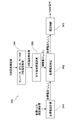
- FIG. 1 is a diagram schematically illustrating a block configuration of a motor drive unit according to the present embodiment.
- FIG. 2 is a diagram showing current values flowing through coils of each phase of the motor in the basic drive control.
- FIG. 3 is a functional block diagram showing functions of the microcontroller shown in FIG.
- FIG. 4 is a diagram showing current values flowing through each coil of each phase of the motor in drive control of two-phase drive.
- FIG. 5 is a diagram showing the current values flowing through the coils of each phase of the motor in the drive control based on the compensation amounts satisfying Expressions (9) and (10).
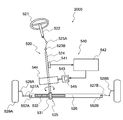
- FIG. 6 is a diagram schematically illustrating the configuration of the power steering device according to the present embodiment.
- FIG. 1 is a diagram schematically illustrating a block configuration of a motor drive unit 1000 according to the present embodiment.
- the motor drive unit 1000 includes a power supply device 100, a motor 200, and a control circuit 300.
- a motor drive unit 1000 including a motor 200 as a component will be described.
- the motor drive unit 1000 including the motor 200 corresponds to an example of the drive device of the present invention.
- the motor drive unit 1000 may be a device for driving the motor 200 in which the motor 200 is omitted as a component.
- the motor drive unit 1000 in which the motor 200 is omitted corresponds to an example of the drive control device of the present invention.
- the motor 200 is, for example, a three-phase AC motor.
- Motor 200 has a-phase, b-phase, and c-phase coils.
- the winding method of the coil is, for example, concentrated winding or distributed winding.
- the motor drive unit 1000 can convert electric power from an external power supply into electric power supplied to the motor 200 by the electric power supply device 100.
- the first inverter 110 and the second inverter 120 can convert DC power into three-phase AC power that is a pseudo sine wave of a phase, b phase, and c phase.
- the power supply device 100 includes a first inverter 110, a second inverter 120, and a current sensor 130.
- the first inverter 110 is connected to one end 210 of the coil of the motor 200
- the second inverter 120 is connected to the other end 220 of the coil of the motor 200.
- “connection” between components (components) mainly means electrical connection.
- the motor 200 is a so-called non-connection motor in which no connection exists between the coils of each phase.
- an SPM motor in which a magnet is provided on a surface of a rotor is employed.
- the first inverter 110 and the second inverter 120 each include a switching element connected to a coil of the motor 200, and power is converted by the switching operation of the switching element and supplied to the motor 200.
- the current sensor 130 includes, for example, a shunt resistor and a current detection circuit, and detects a current flowing through each phase coil of the motor 200 by detecting a current flowing through the first inverter 110 and the second inverter 120.
- the control circuit 300 includes, for example, a power supply circuit 310, an angle sensor 320, an input circuit 330, a microcontroller 340, a drive circuit 350, and a ROM 360.
- Control circuit 300 drives motor 200 by controlling the overall operation of power conversion device 100. Specifically, the control circuit 300 can implement closed-loop control by controlling the target motor torque and rotation speed.
- the power supply circuit 310 generates a DC voltage (for example, 3 V, 5 V) required for each block in the circuit.
- the angle sensor 320 is, for example, a resolver or a Hall IC, or is realized by a combination of an MR sensor having a magnetoresistive (MR) element and a sensor magnet. Angle sensor 320 detects the rotation angle of the rotor of motor 200 and outputs a rotation signal indicating the detected rotation angle to microcontroller 340. Depending on the motor control method (for example, sensorless control), the angle sensor 320 may be omitted.
- the input circuit 330 receives the current value detected by the current sensor 130 (hereinafter, referred to as “actual current value”), and converts the level of the actual current value to the input level of the microcontroller 340 as necessary. , And outputs the actual current value to the microcontroller 340.
- the input circuit 330 is an analog-to-digital conversion circuit.
- the microcontroller 340 receives the rotor rotation signal detected by the angle sensor 320 and receives the actual current value output from the input circuit 330.
- the microcontroller 340 sets a target current value according to the actual current value and the rotation signal of the rotor, generates a PWM signal, and outputs the generated PWM signal to the drive circuit 350.
- the microcontroller 340 generates a PWM signal for controlling a switching operation (turn-on or turn-off) of each switch element in the first inverter 110 and the second inverter 120 of the power supply device 100.
- Drive circuit 350 is typically a gate driver.
- the drive circuit 350 generates a control signal (for example, a gate control signal) for controlling the switching operation of each switch element in the first and second inverters 110 and 120 according to the PWM signal, and supplies the generated control signal to each switch element.
- a control signal for example, a gate control signal
- the microcontroller 340 may have the function of the drive circuit 350. In that case, the control circuit 300 may not include the drive circuit 350.
- the ROM 360 is, for example, a writable memory (for example, PROM), a rewritable memory (for example, flash memory), or a read-only memory.
- the ROM 360 stores a control program including a group of instructions for causing the microcontroller 340 to control the power supply device 100 (mainly, the inverters 110 and 120). (Basic drive control) A specific example of basic control of the inverters 110 and 120 by the control circuit 300 will be described.
- the control circuit 300 sets a balanced current for each phase of the motor 200 as a target value, and generates a balanced PWM signal for each phase according to the balanced target value.
- the inverters 110 and 120 apply a balanced voltage to each phase of the motor 200 by the switching operation according to such a balanced PWM signal.
- the control circuit 300 applies a sinusoidal current to each phase by so-called three-phase conduction control.
- FIG. 2 is a diagram showing the value of current flowing through each coil of each phase of the motor 200 in the basic drive control.
- FIG. 2 plots the current values flowing through the coils of phase a, phase b and phase c of motor 200 when first inverter 110 and second inverter 120 are controlled according to the three-phase energization control based on the basic drive control.
- An example of the current waveform (sine wave) obtained is as follows.
- the horizontal axis in FIG. 2 indicates the motor electrical angle (deg), and the vertical axis indicates the current value (A).
- Ipk represents the maximum current value (peak current value) of each phase.
- the power supply device 100 can also drive the motor 200 using, for example, a rectangular wave other than the sine wave illustrated in FIG.
- FIG. 3 is a functional block diagram showing functions of the microcontroller 340 shown in FIG.
- the microcontroller 340 includes a target current calculation unit 341, a target current correction unit 342, a current control unit 343, a temperature estimation unit 344, and an unbalance compensation amount calculation unit 345 as internal functions.
- the target torque to be generated by the motor 200 is input to the target current calculation unit 341.
- This target torque is given as a target from outside the motor drive unit 1000.
- a measured value of the speed of the vehicle may be input to the target current calculator 341.
- the target current corrector 342 corrects the target current values Id, Iq, Iz in response to an unbalance compensation amount described later, and outputs the corrected target current values Id, Iq, Iz to the current controller 343. .
- the current control unit 343 converts the input target current values Id, Iq, Iz into current values Ia, Ib, Ic to be given to the respective phases a, b, and c of the motor 200, and the current values Ia, Ib , Ic in the inverters 110 and 120.
- the temperature estimating unit 344 receives the input of the above-described actual current value, and estimates the temperatures of the a-phase, the b-phase, and the c-phase. For the estimation of the temperature, an applied voltage value when the actual current value is measured is also used, and a temperature that satisfies the relationship between the voltage and the current is obtained. In other words, the temperature estimating unit 344 estimates the temperature of each phase of the motor 200 from the detected current value (actual current value) in each phase.
- the temperature estimated by temperature estimating section 344 may be the temperature of motor 200 or the temperatures of inverters 110 and 120.
- the unbalance compensation amount calculation unit 345 the mutual imbalance of the three phases of the motor 200 is obtained based on the temperature estimated by the temperature estimation unit 344. That is, the unbalance compensation amount calculation unit 345 calculates the unbalance of the current loss based on the temperature estimated by the temperature estimation unit 344. Then, the unbalance compensation amount calculation unit 345 calculates, as a compensation amount, a current value that causes each phase to generate heat necessary to compensate for the unbalance.
- the imbalance of the current loss is easily calculated by passing the estimated temperature in each phase of the motor 200, and the compensation amount for appropriately suppressing the imbalance is also easily calculated.
- the unbalance calculated by the unbalance compensation amount calculating unit 345 indicates that the three phases of the motor 200 It is an electrical imbalance occurring between them.
- the unbalance compensation amount calculation unit 345 calculates the electrical unbalance between phases in the motor 200.
- the unbalance of the current loss is calculated by the unbalance compensation amount calculation unit 345.
- An imbalance in current loss (i.e., an imbalance in impedance) causes an imbalance in generated torque, and may cause torque ripple. Also, the current loss imbalance results in a temperature imbalance, and the temperature imbalance results in a further current loss imbalance. Since the temperature imbalance is not eliminated even if the current value of each phase is balanced, the unbalance compensation amount calculation unit 345 calculates the current value of each phase that generates heat to cancel the temperature imbalance as the compensation amount. . In addition, as described below, a compensation amount of a current in an axis direction other than the q axis is calculated as a compensation amount for maintaining the target torque. (Method of calculating compensation amount)
- the transformation matrix C from the three phases (abc phase) of the motor 200 to the qdz axis of the rotating coordinate system is given by the following equation (1).
- the generated torque of the motor 200 uniquely corresponds to the current value Iq on the q-axis. Therefore, if the current value Iq is constant, the generated torque of the motor 200 is also constant. From the above equation (2), the correspondence between the current value Iq on the q-axis and the current values Ia, Ib, Ic of the a-phase, b-phase, and c-phase is obtained as in the following equation (3).
- ⁇ Ia, ⁇ Ib, and ⁇ Ic are converted into components in the qdz axis direction by the following equation (6) using the transformation matrix C of the above equation (1).
- the unbalance compensation amount calculation unit 345 calculates the compensation amounts ⁇ Id and ⁇ Iz using the above equation (7). That is, the unbalance compensation amount calculation unit 345 determines whether an imbalance has occurred between any two of the phases b and c of the motor 200 and the other phase a. , The current compensation value ⁇ Id in the d-axis direction and the current compensation value ⁇ Iz in the z-axis direction are calculated by the above-mentioned relational expression (7). By using the relational expression (7), the compensation amounts ⁇ Id and ⁇ Iz can be easily calculated.
- the target current correction unit 342 adds the compensation amounts ⁇ Id, ⁇ Iz to the target currents Id, Iq, Iz. That is, the target current correction unit 342 reduces the imbalance of the motor 200 by adding the compensation value to the control value of the current in the axis direction other than the q axis among the control values calculated by the target current calculation unit 341.
- the motor 200 is a connectionless motor, and the target current correction unit 342 adds a compensation value for both the d-axis and the z-axis.
- the z-axis compensation value By using the z-axis compensation value in this way, a so-called zero-phase current is effectively used.
- the motor 200 in the present embodiment is an SPM motor, no reluctance torque is generated in the motor 200, and both the d-axis and the z-axis are effectively used as imbalance correction. .
- FIG. 4 is a diagram showing current values flowing through each coil of each phase of the motor 200 in drive control of two-phase drive.
- FIG. 4 shows a current obtained by plotting a current value flowing through each of the a-phase, b-phase, and c-phase coils of motor 200 when first inverter 110 and second inverter 120 are controlled according to the two-phase drive control.
- a waveform (sine wave) is exemplified.
- the horizontal axis in FIG. 4 indicates the motor electrical angle (deg), and the vertical axis indicates the current value (A).
- the current value of the b-phase is “0”. Further, in the basic control before the correction based on the compensation amount, the current waveforms of the a-phase and the c-phase are different from each other by 120 ° as shown in FIG. Are different in phase from each other by 60 °.
- ⁇ Ib, ⁇ Ic represented by the following equation (9) can be considered.
- ⁇ Ia corresponding to ⁇ Ib and ⁇ Ic represented by the equation (9) is represented by the following equation (10) obtained by using the above-described various relational expressions and the like.
- FIG. 5 is a diagram illustrating a current value flowing through each coil of each phase of the motor 200 in the drive control based on the compensation amount satisfying Expressions (9) and (10).
- the horizontal axis in FIG. 5 indicates the motor electrical angle (deg), and the vertical axis indicates the current value (A).
- the current waveform when a compensation amount satisfying Expressions (9) and (10) is used is a complicated waveform as shown in FIG. 5, and is a contrasting waveform between the b-phase and the c-phase.
- a current value that generates a calorific value that suppresses temperature imbalance is calculated as the compensation value, but the compensation value is generated between the phases of the torque generated by the motor 200.
- a current value that suppresses imbalance may be calculated.
- Vehicles such as automobiles generally include a power steering device.
- the power steering device generates an assist torque for assisting a steering torque of a steering system generated by a driver operating a steering handle.
- the auxiliary torque is generated by the auxiliary torque mechanism, and can reduce the burden of the driver's operation.
- the auxiliary torque mechanism includes a steering torque sensor, an ECU, a motor, a speed reduction mechanism, and the like.
- the steering torque sensor detects a steering torque in a steering system.
- the ECU generates a drive signal based on the detection signal of the steering torque sensor.
- the motor generates an auxiliary torque according to the steering torque based on the drive signal, and transmits the auxiliary torque to the steering system via the speed reduction mechanism.
- FIG. 6 is a diagram schematically illustrating the configuration of the power steering device 2000 according to the present embodiment.
- the electric power steering apparatus 2000 includes a steering system 520 and an auxiliary torque mechanism 540.
- the steering system 520 is, for example, a steering handle 521, a steering shaft 522 (also referred to as a “steering column”), a universal joint 523A, 523B, and a rotating shaft 524 (also referred to as a “pinion shaft” or “input shaft”). ).
- the steering system 520 includes, for example, a rack and pinion mechanism 525, a rack shaft 526, left and right ball joints 552A and 552B, tie rods 527A and 527B, knuckles 528A and 528B, and left and right steering wheels (for example, left and right front wheels) 529A. 529B.
- a rack and pinion mechanism 525 for example, a rack and pinion mechanism 525, a rack shaft 526, left and right ball joints 552A and 552B, tie rods 527A and 527B, knuckles 528A and 528B, and left and right steering wheels (for example, left and right front wheels) 529A. 529B.
- the steering handle 521 is connected to a rotating shaft 524 via a steering shaft 522 and universal shaft joints 523A and 523B.
- a rack shaft 526 is connected to the rotation shaft 524 via a rack and pinion mechanism 525.
- the rack and pinion mechanism 525 has a pinion 531 provided on the rotation shaft 524 and a rack 532 provided on the rack shaft 526.
- the right steering wheel 529A is connected to the right end of the rack shaft 526 via a ball joint 552A, a tie rod 527A, and a knuckle 528A in this order.
- the left steering wheel 529B is connected to the left end of the rack shaft 526 via a ball joint 552B, a tie rod 527B, and a knuckle 528B in this order.
- the right side and the left side respectively correspond to the right side and the left side viewed from the driver sitting on the seat.
- a steering torque is generated and transmitted to the left and right steering wheels 529A and 529B via the rack and pinion mechanism 525.
- the driver can operate the left and right steering wheels 529A, 529B.
- the auxiliary torque mechanism 540 includes, for example, a steering torque sensor 541, an ECU 542, a motor 543, a speed reduction mechanism 544, and a power supply device 545.
- the auxiliary torque mechanism 540 applies an auxiliary torque to a steering system 520 from the steering handle 521 to the left and right steering wheels 529A, 529B. Note that the auxiliary torque may be referred to as “additional torque”.
- the control circuit 300 shown in FIG. 1 is used.
- the power supply device 545 for example, the power supply device 100 illustrated in FIG. 1 is used.
- the motor 543 for example, the motor 200 shown in FIG. 1 is used.
- the ECU 542, the motor 543, and the power supply device 545 may constitute a unit generally referred to as a "mechanical integrated motor".
- a mechanism configured by elements excluding the ECU 542, the motor 543, and the power supply device 545 among the elements illustrated in FIG. 6 corresponds to an example of a power steering mechanism driven by the motor 543.
- the steering torque sensor 541 detects the steering torque of the steering system 520 given by the steering handle 521.
- the ECU 542 generates a drive signal for driving the motor 543 based on a detection signal (hereinafter, referred to as “torque signal”) from the steering torque sensor 541.
- the motor 543 generates an auxiliary torque corresponding to the steering torque based on the drive signal.
- the assist torque is transmitted to the rotation shaft 524 of the steering system 520 via the speed reduction mechanism 544.
- the reduction mechanism 544 is, for example, a worm gear mechanism.
- the auxiliary torque is further transmitted from the rotation shaft 524 to the rack and pinion mechanism 525.
- the power steering apparatus 2000 is classified into a pinion assist type, a rack assist type, a column assist type, and the like, depending on a position where the assist torque is applied to the steering system 520.
- FIG. 6 shows a pinion assist type power steering device 2000.
- the power steering device 2000 is also applied to a rack assist type, a column assist type, and the like.
- the ECU 542 may receive not only a torque signal but also a vehicle speed signal, for example.
- the microcontroller of the ECU 542 can control the motor 543 based on a torque signal, a vehicle speed signal, and the like.
- the ECU 542 sets a target current value based at least on the torque signal.
- the ECU 542 preferably sets the target current value in consideration of the vehicle speed signal detected by the vehicle speed sensor and further considering the rotation signal of the rotor detected by the angle sensor.
- the ECU 542 can control the drive signal of the motor 543, that is, the drive current, so that the actual current value detected by the current sensor (see FIG. 1) matches the target current value.
- the left and right steering wheels 529A and 529B can be operated by the rack shaft 526 using the combined torque obtained by adding the assisting torque of the motor 543 to the steering torque of the driver.
- the motor drive unit 1000 of the above-described embodiment for the above-described electromechanical integrated motor the occurrence of torque ripple is suppressed even during low-speed steering, and smooth power assist is realized.
- the present invention has been applied for the purpose of reducing an unbalanced state in a power steering device or the like, but the present invention may be applied for other purposes.
- the motor may be intentionally heated to apply heat to an air conditioner (air conditioner) for a vehicle. More specifically, the current of each phase abc is superimposed on the zero-phase current that does not contribute to the torque. By increasing the amount of current, the motor can generate heat. The heat generated by the motor is used for heating the air conditioner (air conditioner) for the vehicle.
- the in-vehicle air conditioning system applied to the conventional engine can be adopted.
- One aspect of the drive control device according to the present invention applied to such another object is a drive control device for controlling the drive of the three-phase motor, and the rotation coordinate of the three-phase motor is controlled according to a given target.
- a control value calculating unit for calculating a control value of a current in each axis direction of the system; and a control value calculated by the control value calculating unit.
- a correction unit for adding to the current.
- a power steering device is given as an example of a use method in the drive control device and the drive device of the present invention, but the use method of the drive control device and the drive device of the present invention is not limited to the above, and a pump, a compressor, and the like. It can be used widely.
- power supply device 110 first inverter 120: second inverter 130: current sensor 200: motor 300: control circuit 310: power supply circuit 320: angle sensor 330: input circuit 340: microcontroller 341: target current calculation unit 342: Target current correction unit 343 #: current control unit 344 #: temperature estimation unit 345 #: unbalance compensation amount calculation unit 350 #: drive circuit 360 #: ROM 1000 #: motor drive unit 2000 #: power steering device
Landscapes
- Engineering & Computer Science (AREA)
- Chemical & Material Sciences (AREA)
- Combustion & Propulsion (AREA)
- Transportation (AREA)
- Mechanical Engineering (AREA)
- Power Engineering (AREA)
- Control Of Ac Motors In General (AREA)
- Power Steering Mechanism (AREA)
Abstract
駆動制御装置の一態様は、3相モータの駆動を制御する駆動制御装置であって、上記3相モータにおける相同士の電気的な不平衡を算出する不平衡算出部と、与えられた目標に従って、上記3相モータの回転座標系の各軸方向における電流の制御値を算出する制御値算出部と、上記制御値算出部で算出された制御値のうちq軸以外の軸方向における電流の制御値に補償値を加算して上記不平衡を減らす平衡補償部と、を備える。
Description
本発明は、駆動制御装置、駆動装置およびパワーステアリング装置に関する。
従来、3相モータの駆動制御装置において、dq軸やdqz軸のようにモータの回転座標系の各軸方向の電流値を制御値として用いる駆動制御装置が知られている。
例えば特許文献1には、q軸電流指令値Iqと、d軸電流指令値Idと、q軸電流検出値Iqと、d軸電流検出値Idと、推定されたロータ角度θとに基づいて、モータに供給される電流を制御するモータ制御装置が開示されている。
モータが低速回転を行う場合、各相の電力損失に差が生じて不平衡状態となる場合がある。このような不平衡状態は、駆動回路の特定部位の温度上昇の原因となったり、コイル線の抵抗における不平衡の原因となったりする。そして、抵抗の不平衡はトルクリップルの原因となる。 そこで、本発明は、3相モータにおける相同士の不平衡を抑制することを目的とする。
本発明に係る駆動制御装置の一態様は、3相モータの駆動を制御する駆動制御装置であって、上記3相モータにおける相同士の電気的な不平衡を算出する不平衡算出部と、与えられた目標に従って、上記3相モータの回転座標系の各軸方向における電流の制御値を算出する制御値算出部と、上記制御値算出部で算出された制御値のうちq軸以外の軸方向における電流の制御値に補償値を加算して上記不平衡を減らす平衡補償部と、を備える。 また、本発明に係る駆動装置の一態様は、上記駆動制御装置と、上記駆動制御装置によって駆動が制御される3相モータと、を備える。
また、本発明に係るパワーステアリング装置の一態様は、上記駆動制御装置と、上記駆動制御装置によって駆動が制御される3相モータと、上記3相モータによって駆動されるパワーステアリング機構と、を備える。
本発明によれば、3相モータにおける相同士の不平衡が抑制される。
以下、添付の図面を参照しながら、本開示の駆動制御装置、駆動装置およびパワーステアリング装置の実施形態を詳細に説明する。但し、以下の説明が不必要に冗長になるのを避け、当業者の理解を容易にするため、必要以上に詳細な説明は省略する場合がある。例えば、既によく知られた事項の詳細説明や実質的に同一の構成に対する重複説明を省略する場合がある。
(モータ駆動ユニット1000の構造)
図1は、本実施形態によるモータ駆動ユニット1000のブロック構成を模式的に示す図である。 モータ駆動ユニット1000は、電力供給装置100、モータ200および制御回路300を備える。
(モータ駆動ユニット1000の構造)
図1は、本実施形態によるモータ駆動ユニット1000のブロック構成を模式的に示す図である。 モータ駆動ユニット1000は、電力供給装置100、モータ200および制御回路300を備える。
本明細書では、構成要素としてモータ200を備えるモータ駆動ユニット1000を説明する。モータ200を備えるモータ駆動ユニット1000は、本発明の駆動装置の一例に相当する。ただし、モータ駆動ユニット1000は、構成要素としてモータ200が省かれた、モータ200を駆動するための装置であってもよい。モータ200が省かれたモータ駆動ユニット1000は、本発明の駆動制御装置の一例に相当する。
モータ200は、例えば3相交流モータである。モータ200は、a相、b相、およびc相のコイルを有する。コイルの巻き方は、例えば集中巻きまたは分布巻きである。
モータ駆動ユニット1000は、外部電源からの電力を、電力供給装置100によってモータ200に供給する電力に変換することが可能である。例えば、第1インバータ110、第2インバータ120は、直流電力を、a相、b相およびc相の擬似正弦波である3相交流電力に変換することが可能である。
電力供給装置100は、第1インバータ110、第2インバータ120、および電流センサ130を備える。第1インバータ110はモータ200のコイルの一端210に接続され、第2インバータ120はモータ200のコイルの他端220に接続される。本明細書において、部品(構成要素)同士の「接続」とは、主に電気的な接続を意味する。モータ200は、各相のコイルの相互間に結線が存在しないいわゆる無結線モータである。また、本実施形態では、一例としてモータ200には、ロータの表面に磁石が配備されたSPMモータが採用される。
第1インバータ110および第2インバータ120は、モータ200のコイルに接続されたスイッチング素子を備え、そのスイッチング素子のスイッチング動作により電力が変換されてモータ200に供給される。
電流センサ130は例えばシャント抵抗と電流検出回路からなり、第1インバータ110および第2インバータ120に流れる電流を検知することで、モータ200の各相のコイルに流れる電流値を検知する。
制御回路300は、例えば、電源回路310と、角度センサ320と、入力回路330と、マイクロコントローラ340と、駆動回路350と、ROM360とを備える。制御回路300は、電力変換装置100の全体の動作を制御することによりモータ200を駆動する。具体的には、制御回路300は、目的とするモータトルクや回転速度を制御してクローズドループ制御を実現することができる。
電源回路310は、回路内の各ブロックに必要なDC電圧(例えば3V、5V)を生成する。角度センサ320は、例えばレゾルバ、ホールICであり、あるいは磁気抵抗(MR)素子を有するMRセンサとセンサマグネットとの組み合わせによっても実現される。角度センサ320は、モータ200のロータの回転角を検出し、検出した回転角を示す回転信号をマイクロコントローラ340に出力する。モータ制御手法(例えばセンサレス制御)によっては、角度センサ320は省かれる場合がある。
入力回路330は、電流センサ130によって検出された電流値(以下、「実電流値」と表記する。)を受け取り、必要に応じて、実電流値のレベルをマイクロコントローラ340の入力レベルに変換し、実電流値をマイクロコントローラ340に出力する。入力回路330は、アナログデジタル変換回路である。
マイクロコントローラ340は、角度センサ320によって検出されたロータの回転信号を受信するとともに、入力回路330から出力された実電流値を受信する。マイクロコントローラ340は、実電流値およびロータの回転信号などに従って目標電流値を設定してPWM信号を生成し、生成したPWM信号を駆動回路350に出力する。例えば、マイクロコントローラ340は、電力供給装置100の第1インバータ110および第2インバータ120における各スイッチ素子のスイッチング動作(ターンオンまたはターンオフ)を制御するためのPWM信号を生成する。
駆動回路350は、典型的にはゲートドライバである。駆動回路350は、第1および第2インバータ110、120における各スイッチ素子のスイッチング動作を制御する制御信号(例えば、ゲート制御信号)をPWM信号に従って生成し、生成した制御信号を各スイッチ素子に与える。なお、マイクロコントローラ340が駆動回路350の機能を備えていてもよい。その場合、制御回路300は駆動回路350を備えていなくてもよい。
ROM360は、例えば書き込み可能なメモリ(例えばPROM)、書き換え可能なメモリ(例えばフラッシュメモリ)または読み出し専用のメモリである。ROM360は、マイクロコントローラ340に電力供給装置100(主としてインバータ110,120)を制御させるための命令群を含む制御プログラムを格納する。
(基本の駆動制御)
制御回路300によるインバータ110、120の基本的な制御の具体例を説明する。
(基本の駆動制御)
制御回路300によるインバータ110、120の基本的な制御の具体例を説明する。
制御回路300は基本的な制御として、モータ200の各相に対して平衡な電流を目標値として設定し、平衡な目標値に従った各相に対して平衡なPWM信号を生成する。このような平衡なPWM信号に従ったスイッチング動作によってインバータ110、120は、モータ200の各相に対して平衡な電圧を印加する。
但し、ここでいう「3相が平衡」とは、3相に同位相の電圧や電流が与えられるという意味では無く、例えば位相が互いに120°ずつ異なった同一振幅の電圧や電流が与えられるという意味である。本実施形態では、一例として、制御回路300はいわゆる3相通電制御によって各相に正弦波の電流を与える。 図2は、基本の駆動制御でモータ200の各相の各コイルに流れる電流値を示す図である。
図2には、基本の駆動制御による3相通電制御に従って第1インバータ110および第2インバータ120が制御されたときにモータ200のa相、b相およびc相の各コイルに流れる電流値をプロットして得られる電流波形(正弦波)が例示される。図2の横軸は、モータ電気角(deg)を示し、縦軸は電流値(A)を示す。Ipkは各相の最大電流値(ピーク電流値)を表す。なお、電力供給装置100は、図2に例示した正弦波以外に、例えば矩形波を用いてモータ200を駆動することも可能である。
このような基本の駆動制御によってモータ200が駆動される場合であっても、モータ200が低速回転を行う場合には、各相の電力損失に差が生じて不平衡状態となる場合がある。このような不平衡状態はトルクリップルの原因ともなるので、本実施形態では、不平衡を抑制する補正制御も実行される。
(不平衡を抑制する補正制御)
図3は、図1に示すマイクロコントローラ340の機能を表した機能ブロック図である。
(不平衡を抑制する補正制御)
図3は、図1に示すマイクロコントローラ340の機能を表した機能ブロック図である。
マイクロコントローラ340は、内部機能として、目標電流計算部341と、目標電流補正部342と、電流制御部343と、温度推定部344と、不平衡補償量計算部345とを有する。
目標電流計算部341には、モータ200で発生させるべき目標トルクが入力される。この目標トルクは、モータ駆動ユニット1000の外部から目標として与えられる。また、モータ駆動ユニット1000が例えばパワーステアリング装置の一部を構成する場合などは、目標電流計算部341には、車両の速度の測定値も入力され得る。
目標電流計算部341は、このような入力値に基づいて、目標トルクがモータ200で得られる電流値を目標電流値として生成する。このとき、目標電流値としては、モータ200における回転座標系のdqz軸それぞれにおける目標電流値Id,Iq,Izが生成される。言い換えると、目標電流計算部341は、与えられた目標に従って、モータ200の回転座標系の各軸方向における電流の制御値を算出する。なお、z軸方向における電流は一般にモータ200のトルク発生に寄与しないので目標電流計算部341は通常、z軸方向における目標電流としてIz=0を算出する。また、モータ200がSPMモータである場合はリラクタンストルクが0であり、d軸方向における電流もモータ200のトルク発生に寄与しないので目標電流計算部341は、d軸方向における目標電流としてId=0を算出する。
目標電流補正部342は、後述する不平衡補償量の入力を受けて目標電流値Id,Iq,Izを補正し、補正後の目標電流値Id,Iq,Izを電流制御部343へと出力する。
電流制御部343は、入力された目標電流値Id,Iq,Izを、モータ200のa相、b相、c相それぞれに与える電流値Ia,Ib,Icに変換し、その電流値Ia,Ib,Icをインバータ110,120に発生させるPWM信号を生成する。
温度推定部344は、上述した実電流値の入力を受け、a相、b相、c相それぞれの温度を推定する。温度の推定には、実電流値が測定された際の印加電圧値も用いられ、電圧と電流の関係を満たす温度が求められる。言い換えると温度推定部344は、モータ200の各相における検出電流値(実電流値)から各相の温度を推定する。温度推定部344により推定される温度は、モータ200の温度でもよく、あるいはインバータ110,120の温度でもよい。
不平衡補償量計算部345では、温度推定部344により推定された温度に基づいて、モータ200の3相の相互に生じている不平衡が求められる。即ち、不平衡補償量計算部345は、温度推定部344で推定された温度に基づいて電流損失の不平衡を算出する。そして、不平衡補償量計算部345は、その不平衡を補償するために必要な発熱を各相に生じさせる電流値を補償量として算出する。モータ200の各相における推定温度を経ることによって電流損失の不平衡が容易に算出されるとともに、不平衡を適切に抑制する補償量の算出も容易となる。
温度推定部344で推定された温度がモータ200の温度であってもインバータ110,120の温度であっても、不平衡補償量計算部345で算出される不平衡はモータ200の3相の相互間に生じている電気的な不平衡である。言い換えると、不平衡補償量計算部345は、モータ200における相同士の電気的な不平衡を算出する。特に本実施形態では不平衡補償量計算部345で電流損失の不平衡が算出される。なお、具体的な算出方法としては周知の技術が適用可能であるためここでは詳細説明を省略する。
電流損失の不平衡(即ちインピーダンスの不平衡)は発生トルクの不平衡を生じるので、トルクリップルの原因となる虞がある。また、電流損失の不平衡は温度の不平衡を生じ、温度の不平衡は更なる電流損失の不平衡を生じる。温度の不平衡は各相の電流値が平衡化されても解消されないため、不平衡補償量計算部345では、温度の不平衡を打ち消す発熱を生じる各相の電流値が補償量として算出される。また、以下説明するように、目標トルクの維持のため補償量としては、q軸以外の軸方向における電流の補償量が算出される。
(補償量の算出方法)
モータ200における3相(abc相)から回転座標系のqdz軸への変換行列Cは、下記式(1)で与えられる。
(補償量の算出方法)
モータ200における3相(abc相)から回転座標系のqdz軸への変換行列Cは、下記式(1)で与えられる。

従って、モータ200の各相(a相、b相、c相)のコイルに各電流値Ia,Ib,Icが流れる場合、モータ200の回転座標系のqdz軸方向それぞれの電流値Iq,Id,Izは以下の式2で求められる。

上述したように本実施形態ではモータ200としてSPMモータが採用されるので、モータ200の発生トルクはq軸における電流値Iqと一意的に対応する。従って、電流値Iqが一定であればモータ200の発生トルクも一定となる。上記式(2)から、q軸における電流値Iqとa相、b相、c相の電流値Ia,Ib,Icとの対応関係は下記式(3)のように求められる。

また、q軸における電流値Iqの変化量をΔIqとし、a相、b相、c相の電流値Ia,Ib,Icにおける変化量をΔIa,ΔIb,ΔIcとすると、下記式(4)が得られる。

ここで、例えばb相、c相の温度がa相よりも高い場合などには、b相、c相において変化量ΔIb,ΔIcに相当する電流が減少される。そして、b相、c相におけるそのような変化量ΔIb,ΔIcに対して電流値Iqが一定(即ちΔIq=0)となるa相の変化量ΔIaは下記式(5)の関係を満たす。

このようなΔIa,-ΔIb,-ΔIcが補償量として用いられることにより、例えばa相における発熱が促されるとともに、b相、c相における発熱が抑えられることになる。そして、このようなΔIa,-ΔIb,-ΔIcが補償量として用いられることにより、目標のトルクは維持される。この結果、モータ200の相同士における温度の不平衡が抑制され、延いては電流損失の不平衡も抑制される。このような補償量ΔIa,-ΔIb,-ΔIcは、上記式(1)の変換行列Cが用いられた下記式(6)によってqdz軸方向の成分に変換される。

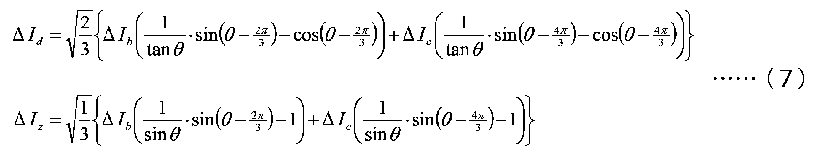
上記不平衡補償量計算部345は、上記式(7)を用いて補償量ΔId,ΔIzを算出する。即ち、不平衡補償量計算部345は、モータ200における各相のうちの任意の2相であるb相、c相と、他の1相であるa相とで不均衡が生じている場合に、d軸方向における電流の補償値ΔIdおよびz軸方向における電流の補償値ΔIzを上記関係式(7)によって算出する。当該関係式(7)が用いられることにより、補償量ΔId,ΔIzが容易に算出される。
そして、目標電流補正部342は、この補償量ΔId,ΔIzを目標電流Id,Iq,Izに加算する。即ち、目標電流補正部342は、目標電流計算部341で算出された制御値のうちq軸以外の軸方向における電流の制御値に補償値を加算してモータ200の不平衡を減らす。
なお、本実施形態では、上述したようにモータ200が無結線モータであり、目標電流補正部342は、d軸とz軸との双方について補償値を加算する。このようにz軸の補償値が用いられることにより、いわゆる零相電流が有効活用される。また、上述したように、本実施形態におけるモータ200はSPMモータであるため、モータ200ではリラクタンストルクが生じず、d軸とz軸との双方が不平衡の補正として有効活用されることになる。
なお、上記関係式(7)は、θ=0の付近では補償量ΔId,ΔIzの値が非常に大きくなるため、そのまま使うことができない。そこで、θ=0の付近で有効な補償量について検討する。 θ=0でも補償量が有限値に留まるための条件は、下記式(8)で表される。

このような式(8)を満たすΔIb,ΔIcの一例としては、ΔIb=ΔIcが考えられる。この場合、上記式(7)からΔId=0が得られ、補償量はΔIzのみとなる。更に、ΔIb=-Ibという条件が加えられると補正後のb相の電流値Ib=0となり、a相とc相のみに電流が与えられる2相駆動となる。 図4は、2相駆動の駆動制御でモータ200の各相の各コイルに流れる電流値を示す図である。
図4には、2相駆動制御に従って第1インバータ110および第2インバータ120が制御されたときにモータ200のa相、b相およびc相の各コイルに流れる電流値をプロットして得られる電流波形(正弦波)が例示される。図4の横軸は、モータ電気角(deg)を示し、縦軸は電流値(A)を示す。
上述したようにb相の電流値は「0」となる。また、補償量による補正前の基本制御では、図2に示すようにa相とc相の電流波形は互いに120°位相が異なる波形であるが、補償量による補正後は、a相とc相の電流波形が互いに60°位相が異なる波形となる。 次に、上記式(8)を満たすΔIb,ΔIcの別の例としては、下記式(9)で表されるΔIb,ΔIcが考えられる。

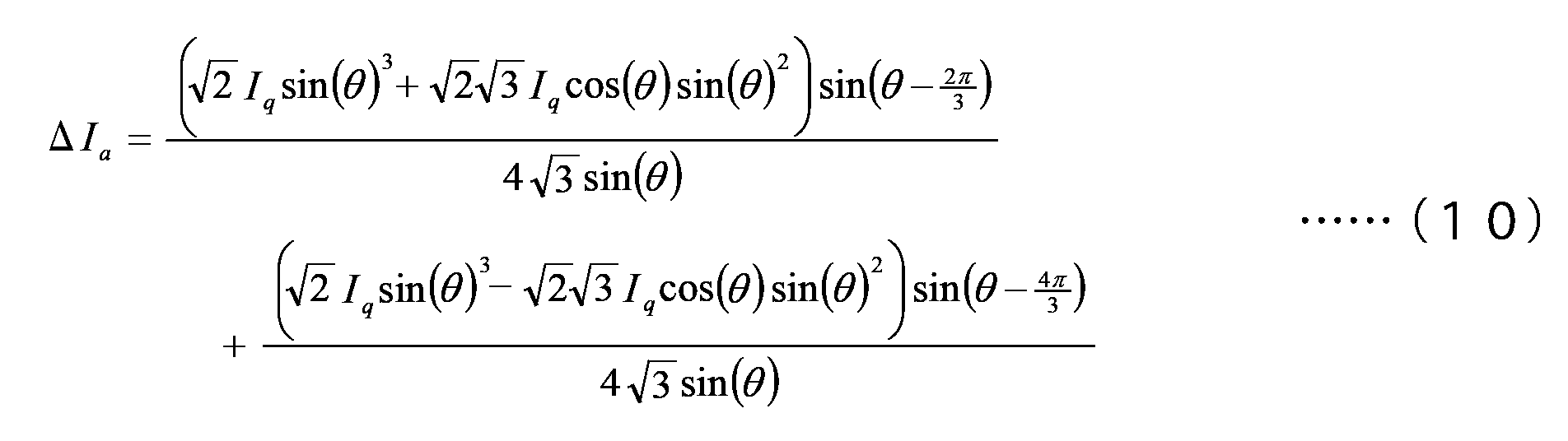
図5は、式(9)、式(10)を満たす補償量による駆動制御でモータ200の各相の各コイルに流れる電流値を示す図である。図5の横軸は、モータ電気角(deg)を示し、縦軸は電流値(A)を示す。 式(9)、式(10)を満たす補償量が用いられた場合の電流波形は、図5に示すような複雑な波形となり、b相とc相とは対照的な波形となる。
図4や図5に示された波形による補償でもΔIq=0の条件を満たしながら不平衡の抑制が実現されるが、上記式(8)の条件が掛かるので、各相の電流値の自由度が低い。このため、図4や図5に示された波形による補償は、θ=0の付近だけで用いられ、それ以外の電気角θでは、上記式(7)で算出される補償量が用いられる。
なお、上記説明では補償値として、温度の不平衡を抑制する発熱量を生じる電流値が算出されるが、補償値としては、モータ200で発生されるトルクについて各相の相互間で生じている不平衡を抑制する電流値が算出されてもよい。
(パワーステアリング装置の実施形態)
(パワーステアリング装置の実施形態)
自動車等の車両は一般的に、パワーステアリング装置を備えている。パワーステアリング装置は、運転者がステアリングハンドルを操作することによって発生するステアリング系の操舵トルクを補助するための補助トルクを生成する。補助トルクは、補助トルク機構によって生成され、運転者の操作の負担を軽減することができる。例えば、補助トルク機構は、操舵トルクセンサ、ECU、モータおよび減速機構などから構成される。操舵トルクセンサは、ステアリング系における操舵トルクを検出する。ECUは、操舵トルクセンサの検出信号に基づいて駆動信号を生成する。モータは、駆動信号に基づいて操舵トルクに応じた補助トルクを生成し、減速機構を介してステアリング系に補助トルクを伝達する。
上記実施形態のモータ駆動ユニット1000は、パワーステアリング装置に好適に利用される。図6は、本実施形態によるパワーステアリング装置2000の構成を模式的に示す図である。 電動パワーステアリング装置2000は、ステアリング系520および補助トルク機構540を備える。
ステアリング系520は、例えば、ステアリングハンドル521、ステアリングシャフト522(「ステアリングコラム」とも称される。)、自在軸継手523A、523B、および回転軸524(「ピニオン軸」または「入力軸」とも称される。)を備える。
また、ステアリング系520は、例えば、ラックアンドピニオン機構525、ラック軸526、左右のボールジョイント552A、552B、タイロッド527A、527B、ナックル528A、528B、および左右の操舵車輪(例えば左右の前輪)529A、529Bを備える。
ステアリングハンドル521は、ステアリングシャフト522と自在軸継手523A、523Bとを介して回転軸524に連結される。回転軸524にはラックアンドピニオン機構525を介してラック軸526が連結される。ラックアンドピニオン機構525は、回転軸524に設けられたピニオン531と、ラック軸526に設けられたラック532とを有する。ラック軸526の右端には、ボールジョイント552A、タイロッド527Aおよびナックル528Aをこの順番で介して右の操舵車輪529Aが連結される。右側と同様に、ラック軸526の左端には、ボールジョイント552B、タイロッド527Bおよびナックル528Bをこの順番で介して左の操舵車輪529Bが連結される。ここで、右側および左側は、座席に座った運転者から見た右側および左側にそれぞれ一致する。
ステアリング系520によれば、運転者がステアリングハンドル521を操作することによって操舵トルクが発生し、ラックアンドピニオン機構525を介して左右の操舵車輪529A、529Bに伝わる。これにより、運転者は左右の操舵車輪529A、529Bを操作することができる。
補助トルク機構540は、例えば、操舵トルクセンサ541、ECU542、モータ543、減速機構544および電力供給装置545を備える。補助トルク機構540は、ステアリングハンドル521から左右の操舵車輪529A、529Bに至るステアリング系520に補助トルクを与える。なお、補助トルクは「付加トルク」と称されることがある。
ECU542としては、例えば図1に示された制御回路300が用いられる。また、電力供給装置545としては、例えば図1に示された電力供給装置100が用いられる。また、モータ543としては、例えば図1に示されたモータ200が用いられる。ECU542、モータ543および電力供給装置545は、一般的に「機電一体型モータ」と称されるユニットを構成してもよい。図6に示された各要素のうち、ECU542、モータ543および電力供給装置545を除いた要素で構成された機構は、モータ543によって駆動されるパワーステアリング機構の一例に相当する。
操舵トルクセンサ541は、ステアリングハンドル521によって付与されたステアリング系520の操舵トルクを検出する。ECU542は、操舵トルクセンサ541からの検出信号(以下、「トルク信号」と表記する。)に基づいてモータ543を駆動するための駆動信号を生成する。モータ543は、操舵トルクに応じた補助トルクを駆動信号に基づいて発生する。補助トルクは、減速機構544を介してステアリング系520の回転軸524に伝達される。減速機構544は、例えばウォームギヤ機構である。補助トルクはさらに、回転軸524からラックアンドピニオン機構525に伝達される。
パワーステアリング装置2000は、補助トルクがステアリング系520に付与される箇所によって、ピニオンアシスト型、ラックアシスト型、およびコラムアシスト型等に分類される。図6には、ピニオンアシスト型のパワーステアリング装置2000が示されている。ただし、パワーステアリング装置2000は、ラックアシスト型、コラムアシスト型等にも適用される。
ECU542には、トルク信号だけでなく、例えば車速信号も入力され得る。ECU542のマイクロコントローラは、トルク信号や車速信号などに基づいてモータ543を制御することができる。
ECU542は、少なくともトルク信号に基づいて目標電流値を設定する。ECU542は、車速センサによって検出された車速信号を考慮し、さらに角度センサによって検出されたロータの回転信号を考慮して、目標電流値を設定することが好ましい。ECU542は、電流センサ(図1参照)によって検出された実電流値が目標電流値に一致するように、モータ543の駆動信号、つまり、駆動電流を制御することができる。
パワーステアリング装置2000によれば、運転者の操舵トルクにモータ543の補助トルクを加えた複合トルクを利用してラック軸526によって左右の操舵車輪529A、529Bを操作することができる。特に、上述した機電一体型モータに、上記実施形態のモータ駆動ユニット1000が利用されることにより、低速な操舵時にもトルクリップルの発生が抑制され、滑らかなパワーアシストが実現される。
(他の変形例)
上記説明では、本発明が、パワーステアリング装置などにおいて不平衡状態を減らすことを目的として適用されたが、本発明は、他の目的として適用されても良い。例えば、トラクション装置において、モータが意図的に発熱されて車内用空調機(エアコン)の暖房に適用されても良い。より詳細に述べると、abc各相の電流がトルクに寄与しない零相電流に重畳される。このように電流量が増えることにより、モータが熱を発生することができる。そして、モータによって生じた熱が車内用空調機(エアコン)の暖房として用いられる。これにより、自動運転等によってエンジンがモータに置き換えられたとしても、従来のエンジンで適用されていた車内空調システムが採用可能となる。
上記説明では、本発明が、パワーステアリング装置などにおいて不平衡状態を減らすことを目的として適用されたが、本発明は、他の目的として適用されても良い。例えば、トラクション装置において、モータが意図的に発熱されて車内用空調機(エアコン)の暖房に適用されても良い。より詳細に述べると、abc各相の電流がトルクに寄与しない零相電流に重畳される。このように電流量が増えることにより、モータが熱を発生することができる。そして、モータによって生じた熱が車内用空調機(エアコン)の暖房として用いられる。これにより、自動運転等によってエンジンがモータに置き換えられたとしても、従来のエンジンで適用されていた車内空調システムが採用可能となる。
このような他の目的に適用される本発明に係る駆動制御装置の一態様は、3相モータの駆動を制御する駆動制御装置であって、与えられた目標に従って、上記3相モータの回転座標系の各軸方向における電流の制御値を算出する制御値算出部と、上記制御値算出部で算出された制御値に対し、上記3相モータにおけるabc各相の電流を零相電流もしくはd軸電流に加算する補正部と、を備える。
なお、ここでは、本発明の駆動制御装置および駆動装置における使用方法の一例としてパワーステアリング装置が挙げられるが、本発明の駆動制御装置および駆動装置の使用方法は上記に限定されず、ポンプ、コンプレッサなど広範囲に使用可能である。
上述した実施形態及び変形例は、すべての点で例示であって制限的なものではないと考えられるべきである。本発明の範囲は上記した実施の形態ではなくて請求の範囲によって示され、請求の範囲と均等の意味及び範囲内でのすべての変更が含まれることが意図される。
100 :電力供給装置110 :第1インバータ120 :第2インバータ130 :電流センサ200 :モータ300 :制御回路310 :電源回路320 :角度センサ330 :入力回路340 :マイクロコントローラ341 :目標電流計算部342 :目標電流補正部343 :電流制御部344 :温度推定部345 :不平衡補償量計算部350 :駆動回路360 :ROM1000 :モータ駆動ユニット2000 :パワーステアリング装置
Claims (7)
- 3相モータの駆動を制御する駆動制御装置であって、
前記3相モータにおける相同士の電気的な不平衡を算出する不平衡算出部と、
与えられた目標に従って、前記3相モータの回転座標系の各軸方向における電流の制御値を算出する制御値算出部と、
前記制御値算出部で算出された制御値のうちq軸以外の軸方向における電流の制御値に補償値を加算して前記不平衡を減らす平衡補償部と、
を備える駆動制御装置。 - 前記3相モータの各相における検出電流値から各相の温度を推定する温度推定部を備え、
前記不平衡算出部は、前記温度推定部で推定された温度に基づいて電流損失の不平衡を算出する請求項1に記載の駆動制御装置。 - 前記3相モータが無結線モータであり、
前記平衡補償部は、d軸とz軸との双方について補償値を加算する請求項1または2に記載の駆動制御装置。 - 前記3相モータが、ロータの表面に磁石が配備されたSPMモータである請求項3に記載の駆動制御装置。
- 前記平衡補償部は、前記3相モータにおける各相のうちの任意の2相であるb相、c相と、他の1相であるa相とで不均衡が生じている場合に、d軸方向における電流の補償値ΔIdおよびz軸方向における電流の補償値ΔIzを、下記関係式

- 請求項1から5のいずれか1項に記載の駆動制御装置と、
前記駆動制御装置によって駆動が制御される3相モータと、
を備える駆動装置。 - 請求項1から5のいずれか1項に記載の駆動制御装置と、
前記駆動制御装置によって駆動が制御される3相モータと、
前記3相モータによって駆動されるパワーステアリング機構と、
を備えるパワーステアリング装置。
Priority Applications (1)
| Application Number | Priority Date | Filing Date | Title |
|---|---|---|---|
| US17/266,108 US11496077B2 (en) | 2018-08-07 | 2019-06-25 | Drive controller, drive unit, and power steering |
Applications Claiming Priority (2)
| Application Number | Priority Date | Filing Date | Title |
|---|---|---|---|
| JP2018148932 | 2018-08-07 | ||
| JP2018-148932 | 2018-08-07 |
Publications (1)
| Publication Number | Publication Date |
|---|---|
| WO2020031526A1 true WO2020031526A1 (ja) | 2020-02-13 |
Family
ID=69414683
Family Applications (1)
| Application Number | Title | Priority Date | Filing Date |
|---|---|---|---|
| PCT/JP2019/025031 Ceased WO2020031526A1 (ja) | 2018-08-07 | 2019-06-25 | 駆動制御装置、駆動装置およびパワーステアリング装置 |
Country Status (2)
| Country | Link |
|---|---|
| US (1) | US11496077B2 (ja) |
| WO (1) | WO2020031526A1 (ja) |
Families Citing this family (4)
| Publication number | Priority date | Publication date | Assignee | Title |
|---|---|---|---|---|
| WO2020013079A1 (ja) * | 2018-07-12 | 2020-01-16 | 日本電産株式会社 | 駆動制御装置、駆動装置およびパワーステアリング装置 |
| WO2020031526A1 (ja) * | 2018-08-07 | 2020-02-13 | 日本電産株式会社 | 駆動制御装置、駆動装置およびパワーステアリング装置 |
| JP7449166B2 (ja) * | 2020-05-22 | 2024-03-13 | 株式会社豊田中央研究所 | モータシステム |
| CN115498939B (zh) * | 2022-09-06 | 2026-04-28 | 东风汽车集团股份有限公司 | 电机三相电流的不平衡补偿方法、装置及电子设备 |
Citations (3)
| Publication number | Priority date | Publication date | Assignee | Title |
|---|---|---|---|---|
| JP2004032917A (ja) * | 2002-06-26 | 2004-01-29 | Nissan Motor Co Ltd | モータ制御装置 |
| JP2011066947A (ja) * | 2009-09-15 | 2011-03-31 | Hitachi Automotive Systems Ltd | モータ制御装置 |
| WO2017009907A1 (ja) * | 2015-07-10 | 2017-01-19 | 三菱電機株式会社 | モータ制御装置、圧縮機、及び空気調和機 |
Family Cites Families (38)
| Publication number | Priority date | Publication date | Assignee | Title |
|---|---|---|---|---|
| JP3488043B2 (ja) * | 1997-05-26 | 2004-01-19 | 株式会社日立製作所 | 永久磁石型同期発電機を備えた駆動システム及びそれを用いた電気車の駆動制御方法 |
| JP3764337B2 (ja) * | 1998-10-30 | 2006-04-05 | 東芝三菱電機産業システム株式会社 | 同期電動機の制御装置 |
| JP3502040B2 (ja) * | 2000-12-27 | 2004-03-02 | 本田技研工業株式会社 | ブラシレスdcモータの定数検出装置およびブラシレスdcモータの制御装置およびブラシレスdcモータの定数検出用プログラム |
| JP4033030B2 (ja) * | 2003-04-21 | 2008-01-16 | 株式会社ジェイテクト | 電動パワーステアリング装置 |
| JP4754428B2 (ja) * | 2006-07-21 | 2011-08-24 | 本田技研工業株式会社 | 電動機の制御装置 |
| JP5130716B2 (ja) * | 2007-01-09 | 2013-01-30 | 株式会社ジェイテクト | モータ制御装置および電気式動力舵取装置 |
| JP5168448B2 (ja) * | 2007-02-26 | 2013-03-21 | 株式会社ジェイテクト | モータ制御装置及び電動パワーステアリング装置 |
| JP5446988B2 (ja) * | 2010-02-25 | 2014-03-19 | 株式会社明電舎 | 回転電気機械のトルクリプル抑制制御装置および制御方法 |
| JP2013085423A (ja) | 2011-10-12 | 2013-05-09 | Jtekt Corp | モータ制御装置および電動パワーステアリング装置 |
| JP6279211B2 (ja) * | 2013-01-31 | 2018-02-14 | Ntn株式会社 | 電気自動車用同期モータの制御装置 |
| US9136785B2 (en) * | 2013-03-12 | 2015-09-15 | Steering Solutions Ip Holding Corporation | Motor control system to compensate for torque ripple |
| US9143081B2 (en) * | 2013-03-14 | 2015-09-22 | Steering Solutions Ip Holding Corporation | Motor control system having bandwidth compensation |
| KR101405237B1 (ko) * | 2013-06-25 | 2014-06-10 | 현대자동차 주식회사 | 친환경 자동차의 모터 제어 시스템 |
| BR112015031352A2 (pt) * | 2013-07-02 | 2017-07-25 | Mitsubishi Electric Corp | dispositivo de controle de motor |
| JP6264257B2 (ja) * | 2014-10-20 | 2018-01-24 | 株式会社明電舎 | 三相中性点クランプ式の電力変換装置 |
| CN104836500A (zh) * | 2014-12-01 | 2015-08-12 | 北汽福田汽车股份有限公司 | 基于电机的弱磁开环控制的转矩补偿方法及电机控制器 |
| JP6693294B2 (ja) * | 2016-06-22 | 2020-05-13 | 株式会社デンソー | 3相回転機の制御装置 |
| US10530245B2 (en) * | 2016-07-20 | 2020-01-07 | Nsk Ltd. | Electric power steering apparatus |
| US10676127B2 (en) * | 2016-07-20 | 2020-06-09 | Nsk Ltd. | Electric power steering apparatus |
| CN109496393B (zh) * | 2016-07-20 | 2020-02-21 | 日本精工株式会社 | 电动助力转向装置 |
| WO2018016356A1 (ja) * | 2016-07-20 | 2018-01-25 | 日本精工株式会社 | 電動パワーステアリング装置 |
| JP6590089B2 (ja) * | 2017-02-13 | 2019-10-16 | 日本精工株式会社 | 電動パワーステアリング装置 |
| JP6601595B2 (ja) * | 2017-06-16 | 2019-11-06 | 日本精工株式会社 | モータ制御装置及びそれを搭載した電動パワーステアリング装置 |
| WO2018230542A1 (ja) * | 2017-06-16 | 2018-12-20 | 日本精工株式会社 | モータ制御装置及びそれを搭載した電動パワーステアリング装置 |
| US10608572B2 (en) * | 2017-10-31 | 2020-03-31 | Nidec Corporation | Motor drive control device |
| JPWO2019163552A1 (ja) * | 2018-02-20 | 2021-03-04 | 日本電産株式会社 | モータ制御システム、およびパワーステアリングシステム |
| CN111713006B (zh) * | 2018-02-20 | 2023-10-13 | 日本电产株式会社 | 马达控制系统和助力转向系统 |
| CN111713007B (zh) * | 2018-02-20 | 2024-03-19 | 日本电产株式会社 | 控制系统、其制造和补偿调整方法、驱动和助力转向装置 |
| WO2019163553A1 (ja) * | 2018-02-20 | 2019-08-29 | 日本電産株式会社 | モータ制御システム、およびパワーステアリングシステム |
| US11601076B2 (en) * | 2018-02-28 | 2023-03-07 | Mitsubishi Electric Corporation | Motor driving apparatus and refrigeration cycle equipment |
| US11264924B2 (en) * | 2018-03-30 | 2022-03-01 | Mitsubishi Electric Corporation | Motor driving apparatus and refrigeration cycle equipment |
| DE112019002412T5 (de) * | 2018-05-11 | 2021-01-28 | Nidec Corporation | Motorsteuervorrichtung, Antriebsvorrichtung und Servolenkvorrichtung |
| JP7114705B2 (ja) * | 2018-06-18 | 2022-08-08 | 三菱電機株式会社 | モータ駆動装置及び冷凍サイクル適用機器 |
| WO2020031526A1 (ja) * | 2018-08-07 | 2020-02-13 | 日本電産株式会社 | 駆動制御装置、駆動装置およびパワーステアリング装置 |
| JP7205108B2 (ja) * | 2018-08-20 | 2023-01-17 | 日本電産株式会社 | モータ制御装置およびパワーステアリング装置 |
| CN110165952B (zh) * | 2019-04-30 | 2021-01-01 | 浙江工业大学 | 一种无电解电容永磁同步电机矢量控制母线电压波动补偿方法 |
| CN110635732A (zh) * | 2019-06-25 | 2019-12-31 | 哈尔滨理工大学 | 一种基于时序滞后补偿的双中断永磁同步电机高速驱动控制方法 |
| CN112398400A (zh) * | 2020-09-12 | 2021-02-23 | 上海新时达电气股份有限公司 | 三相电机电流限制方法及其装置 |
-
2019
- 2019-06-25 WO PCT/JP2019/025031 patent/WO2020031526A1/ja not_active Ceased
- 2019-06-25 US US17/266,108 patent/US11496077B2/en active Active
Patent Citations (3)
| Publication number | Priority date | Publication date | Assignee | Title |
|---|---|---|---|---|
| JP2004032917A (ja) * | 2002-06-26 | 2004-01-29 | Nissan Motor Co Ltd | モータ制御装置 |
| JP2011066947A (ja) * | 2009-09-15 | 2011-03-31 | Hitachi Automotive Systems Ltd | モータ制御装置 |
| WO2017009907A1 (ja) * | 2015-07-10 | 2017-01-19 | 三菱電機株式会社 | モータ制御装置、圧縮機、及び空気調和機 |
Also Published As
| Publication number | Publication date |
|---|---|
| US20210229735A1 (en) | 2021-07-29 |
| US11496077B2 (en) | 2022-11-08 |
Similar Documents
| Publication | Publication Date | Title |
|---|---|---|
| JP5365701B2 (ja) | 電動パワーステアリング装置 | |
| JP5387630B2 (ja) | 多相回転機の制御装置、及びこれを用いた電動パワーステアリング装置 | |
| JP5907314B2 (ja) | モータ制御装置、これを使用した電動パワーステアリング装置および車両 | |
| JP6583592B1 (ja) | モータ制御装置及びこれを備えた電動パワーステアリング装置 | |
| JP5168448B2 (ja) | モータ制御装置及び電動パワーステアリング装置 | |
| JP5942337B2 (ja) | 車両用操舵装置 | |
| JP5092760B2 (ja) | モータ制御装置および電動パワーステアリング装置 | |
| EP1470988B1 (en) | Electric power steering apparatus | |
| WO2009123113A1 (ja) | モータ制御装置および電動パワーステアリング装置 | |
| US11496077B2 (en) | Drive controller, drive unit, and power steering | |
| US12184209B2 (en) | Motor control device and steering system | |
| WO2009087991A1 (ja) | モータ制御装置および電動パワーステアリング装置 | |
| JP5605334B2 (ja) | 多相回転機の制御装置 | |
| JP2009247181A (ja) | モータ制御装置および電動パワーステアリング装置 | |
| JP2008168669A (ja) | 電動パワーステアリング装置 | |
| JP6965697B2 (ja) | 操舵制御装置 | |
| JP2011010534A (ja) | モータ制御装置および電動パワーステアリング装置 | |
| JP7331778B2 (ja) | モータ制御装置 | |
| JP2011131643A (ja) | 電動パワーステアリング装置 | |
| JP5719177B2 (ja) | 電動パワーステアリング装置 | |
| JP2011157004A (ja) | 電動パワーステアリング装置 | |
| JP4123827B2 (ja) | 電流検出装置を用いた制御装置 | |
| JP2012157096A (ja) | モータ制御装置、および、これを用いた電動パワーステアリング装置 | |
| JP2011230531A (ja) | モータ制御装置 | |
| JP5141955B2 (ja) | モータ制御装置 |
Legal Events
| Date | Code | Title | Description |
|---|---|---|---|
| 121 | Ep: the epo has been informed by wipo that ep was designated in this application |
Ref document number: 19846755 Country of ref document: EP Kind code of ref document: A1 |
|
| NENP | Non-entry into the national phase |
Ref country code: DE |
|
| 122 | Ep: pct application non-entry in european phase |
Ref document number: 19846755 Country of ref document: EP Kind code of ref document: A1 |
|
| NENP | Non-entry into the national phase |
Ref country code: JP |