WO2020004024A1 - 作業車 - Google Patents
作業車 Download PDFInfo
- Publication number
- WO2020004024A1 WO2020004024A1 PCT/JP2019/023212 JP2019023212W WO2020004024A1 WO 2020004024 A1 WO2020004024 A1 WO 2020004024A1 JP 2019023212 W JP2019023212 W JP 2019023212W WO 2020004024 A1 WO2020004024 A1 WO 2020004024A1
- Authority
- WO
- WIPO (PCT)
- Prior art keywords
- link
- traveling
- vehicle body
- hydraulic
- wheel
- Prior art date
Links
Images


Classifications
-
- B—PERFORMING OPERATIONS; TRANSPORTING
- B60—VEHICLES IN GENERAL
- B60G—VEHICLE SUSPENSION ARRANGEMENTS
- B60G17/00—Resilient suspensions having means for adjusting the spring or vibration-damper characteristics, for regulating the distance between a supporting surface and a sprung part of vehicle or for locking suspension during use to meet varying vehicular or surface conditions, e.g. due to speed or load
- B60G17/015—Resilient suspensions having means for adjusting the spring or vibration-damper characteristics, for regulating the distance between a supporting surface and a sprung part of vehicle or for locking suspension during use to meet varying vehicular or surface conditions, e.g. due to speed or load the regulating means comprising electric or electronic elements
- B60G17/016—Resilient suspensions having means for adjusting the spring or vibration-damper characteristics, for regulating the distance between a supporting surface and a sprung part of vehicle or for locking suspension during use to meet varying vehicular or surface conditions, e.g. due to speed or load the regulating means comprising electric or electronic elements characterised by their responsiveness, when the vehicle is travelling, to specific motion, a specific condition, or driver input
- B60G17/0165—Resilient suspensions having means for adjusting the spring or vibration-damper characteristics, for regulating the distance between a supporting surface and a sprung part of vehicle or for locking suspension during use to meet varying vehicular or surface conditions, e.g. due to speed or load the regulating means comprising electric or electronic elements characterised by their responsiveness, when the vehicle is travelling, to specific motion, a specific condition, or driver input to an external condition, e.g. rough road surface, side wind
-
- B—PERFORMING OPERATIONS; TRANSPORTING
- B62—LAND VEHICLES FOR TRAVELLING OTHERWISE THAN ON RAILS
- B62D—MOTOR VEHICLES; TRAILERS
- B62D61/00—Motor vehicles or trailers, characterised by the arrangement or number of wheels, not otherwise provided for, e.g. four wheels in diamond pattern
- B62D61/12—Motor vehicles or trailers, characterised by the arrangement or number of wheels, not otherwise provided for, e.g. four wheels in diamond pattern with variable number of ground engaging wheels, e.g. with some wheels arranged higher than others, or with retractable wheels
-
- B—PERFORMING OPERATIONS; TRANSPORTING
- B60—VEHICLES IN GENERAL
- B60G—VEHICLE SUSPENSION ARRANGEMENTS
- B60G17/00—Resilient suspensions having means for adjusting the spring or vibration-damper characteristics, for regulating the distance between a supporting surface and a sprung part of vehicle or for locking suspension during use to meet varying vehicular or surface conditions, e.g. due to speed or load
- B60G17/015—Resilient suspensions having means for adjusting the spring or vibration-damper characteristics, for regulating the distance between a supporting surface and a sprung part of vehicle or for locking suspension during use to meet varying vehicular or surface conditions, e.g. due to speed or load the regulating means comprising electric or electronic elements
- B60G17/016—Resilient suspensions having means for adjusting the spring or vibration-damper characteristics, for regulating the distance between a supporting surface and a sprung part of vehicle or for locking suspension during use to meet varying vehicular or surface conditions, e.g. due to speed or load the regulating means comprising electric or electronic elements characterised by their responsiveness, when the vehicle is travelling, to specific motion, a specific condition, or driver input
- B60G17/0162—Resilient suspensions having means for adjusting the spring or vibration-damper characteristics, for regulating the distance between a supporting surface and a sprung part of vehicle or for locking suspension during use to meet varying vehicular or surface conditions, e.g. due to speed or load the regulating means comprising electric or electronic elements characterised by their responsiveness, when the vehicle is travelling, to specific motion, a specific condition, or driver input mainly during a motion involving steering operation, e.g. cornering, overtaking
-
- B—PERFORMING OPERATIONS; TRANSPORTING
- B60—VEHICLES IN GENERAL
- B60G—VEHICLE SUSPENSION ARRANGEMENTS
- B60G17/00—Resilient suspensions having means for adjusting the spring or vibration-damper characteristics, for regulating the distance between a supporting surface and a sprung part of vehicle or for locking suspension during use to meet varying vehicular or surface conditions, e.g. due to speed or load
- B60G17/015—Resilient suspensions having means for adjusting the spring or vibration-damper characteristics, for regulating the distance between a supporting surface and a sprung part of vehicle or for locking suspension during use to meet varying vehicular or surface conditions, e.g. due to speed or load the regulating means comprising electric or electronic elements
- B60G17/016—Resilient suspensions having means for adjusting the spring or vibration-damper characteristics, for regulating the distance between a supporting surface and a sprung part of vehicle or for locking suspension during use to meet varying vehicular or surface conditions, e.g. due to speed or load the regulating means comprising electric or electronic elements characterised by their responsiveness, when the vehicle is travelling, to specific motion, a specific condition, or driver input
- B60G17/0164—Resilient suspensions having means for adjusting the spring or vibration-damper characteristics, for regulating the distance between a supporting surface and a sprung part of vehicle or for locking suspension during use to meet varying vehicular or surface conditions, e.g. due to speed or load the regulating means comprising electric or electronic elements characterised by their responsiveness, when the vehicle is travelling, to specific motion, a specific condition, or driver input mainly during accelerating or braking
-
- B—PERFORMING OPERATIONS; TRANSPORTING
- B60—VEHICLES IN GENERAL
- B60G—VEHICLE SUSPENSION ARRANGEMENTS
- B60G3/00—Resilient suspensions for a single wheel
- B60G3/18—Resilient suspensions for a single wheel with two or more pivoted arms, e.g. parallelogram
- B60G3/185—Resilient suspensions for a single wheel with two or more pivoted arms, e.g. parallelogram the arms being essentially parallel to the longitudinal axis of the vehicle
-
- B—PERFORMING OPERATIONS; TRANSPORTING
- B60—VEHICLES IN GENERAL
- B60G—VEHICLE SUSPENSION ARRANGEMENTS
- B60G3/00—Resilient suspensions for a single wheel
- B60G3/18—Resilient suspensions for a single wheel with two or more pivoted arms, e.g. parallelogram
- B60G3/20—Resilient suspensions for a single wheel with two or more pivoted arms, e.g. parallelogram all arms being rigid
-
- B—PERFORMING OPERATIONS; TRANSPORTING
- B60—VEHICLES IN GENERAL
- B60G—VEHICLE SUSPENSION ARRANGEMENTS
- B60G5/00—Resilient suspensions for a set of tandem wheels or axles having interrelated movements
-
- E—FIXED CONSTRUCTIONS
- E02—HYDRAULIC ENGINEERING; FOUNDATIONS; SOIL SHIFTING
- E02F—DREDGING; SOIL-SHIFTING
- E02F9/00—Component parts of dredgers or soil-shifting machines, not restricted to one of the kinds covered by groups E02F3/00 - E02F7/00
- E02F9/08—Superstructures; Supports for superstructures
- E02F9/0841—Articulated frame, i.e. having at least one pivot point between two travelling gear units
-
- E—FIXED CONSTRUCTIONS
- E02—HYDRAULIC ENGINEERING; FOUNDATIONS; SOIL SHIFTING
- E02F—DREDGING; SOIL-SHIFTING
- E02F9/00—Component parts of dredgers or soil-shifting machines, not restricted to one of the kinds covered by groups E02F3/00 - E02F7/00
- E02F9/20—Drives; Control devices
- E02F9/22—Hydraulic or pneumatic drives
- E02F9/225—Control of steering, e.g. for hydraulic motors driving the vehicle tracks
-
- E—FIXED CONSTRUCTIONS
- E02—HYDRAULIC ENGINEERING; FOUNDATIONS; SOIL SHIFTING
- E02F—DREDGING; SOIL-SHIFTING
- E02F9/00—Component parts of dredgers or soil-shifting machines, not restricted to one of the kinds covered by groups E02F3/00 - E02F7/00
- E02F9/20—Drives; Control devices
- E02F9/22—Hydraulic or pneumatic drives
- E02F9/2257—Vehicle levelling or suspension systems
-
- B—PERFORMING OPERATIONS; TRANSPORTING
- B60—VEHICLES IN GENERAL
- B60G—VEHICLE SUSPENSION ARRANGEMENTS
- B60G2200/00—Indexing codes relating to suspension types
- B60G2200/10—Independent suspensions
- B60G2200/13—Independent suspensions with longitudinal arms only
-
- B—PERFORMING OPERATIONS; TRANSPORTING
- B60—VEHICLES IN GENERAL
- B60G—VEHICLE SUSPENSION ARRANGEMENTS
- B60G2200/00—Indexing codes relating to suspension types
- B60G2200/40—Indexing codes relating to the wheels in the suspensions
- B60G2200/44—Indexing codes relating to the wheels in the suspensions steerable
-
- B—PERFORMING OPERATIONS; TRANSPORTING
- B60—VEHICLES IN GENERAL
- B60G—VEHICLE SUSPENSION ARRANGEMENTS
- B60G2202/00—Indexing codes relating to the type of spring, damper or actuator
- B60G2202/40—Type of actuator
- B60G2202/41—Fluid actuator
- B60G2202/413—Hydraulic actuator
-
- B—PERFORMING OPERATIONS; TRANSPORTING
- B60—VEHICLES IN GENERAL
- B60G—VEHICLE SUSPENSION ARRANGEMENTS
- B60G2300/00—Indexing codes relating to the type of vehicle
- B60G2300/08—Agricultural vehicles
-
- B—PERFORMING OPERATIONS; TRANSPORTING
- B60—VEHICLES IN GENERAL
- B60G—VEHICLE SUSPENSION ARRANGEMENTS
- B60G2400/00—Indexing codes relating to detected, measured or calculated conditions or factors
- B60G2400/20—Speed
- B60G2400/204—Vehicle speed
-
- B—PERFORMING OPERATIONS; TRANSPORTING
- B60—VEHICLES IN GENERAL
- B60G—VEHICLE SUSPENSION ARRANGEMENTS
- B60G2400/00—Indexing codes relating to detected, measured or calculated conditions or factors
- B60G2400/20—Speed
- B60G2400/208—Speed of wheel rotation
-
- B—PERFORMING OPERATIONS; TRANSPORTING
- B60—VEHICLES IN GENERAL
- B60G—VEHICLE SUSPENSION ARRANGEMENTS
- B60G2400/00—Indexing codes relating to detected, measured or calculated conditions or factors
- B60G2400/25—Stroke; Height; Displacement
- B60G2400/252—Stroke; Height; Displacement vertical
-
- B—PERFORMING OPERATIONS; TRANSPORTING
- B60—VEHICLES IN GENERAL
- B60G—VEHICLE SUSPENSION ARRANGEMENTS
- B60G2400/00—Indexing codes relating to detected, measured or calculated conditions or factors
- B60G2400/50—Pressure
- B60G2400/51—Pressure in suspension unit
-
- B—PERFORMING OPERATIONS; TRANSPORTING
- B60—VEHICLES IN GENERAL
- B60G—VEHICLE SUSPENSION ARRANGEMENTS
- B60G2400/00—Indexing codes relating to detected, measured or calculated conditions or factors
- B60G2400/60—Load
-
- B—PERFORMING OPERATIONS; TRANSPORTING
- B60—VEHICLES IN GENERAL
- B60G—VEHICLE SUSPENSION ARRANGEMENTS
- B60G2400/00—Indexing codes relating to detected, measured or calculated conditions or factors
- B60G2400/60—Load
- B60G2400/64—Wheel forces, e.g. on hub, spindle or bearing
-
- B—PERFORMING OPERATIONS; TRANSPORTING
- B60—VEHICLES IN GENERAL
- B60G—VEHICLE SUSPENSION ARRANGEMENTS
- B60G2500/00—Indexing codes relating to the regulated action or device
- B60G2500/30—Height or ground clearance
-
- B—PERFORMING OPERATIONS; TRANSPORTING
- B60—VEHICLES IN GENERAL
- B60G—VEHICLE SUSPENSION ARRANGEMENTS
- B60G2800/00—Indexing codes relating to the type of movement or to the condition of the vehicle and to the end result to be achieved by the control action
- B60G2800/01—Attitude or posture control
Definitions
- the present invention relates to a work vehicle suitable for traveling on a road surface (rough terrain) having many irregularities.
- the work vehicle includes, but is not limited to, a four-wheel drive robot described below.
- the vehicle body can maintain an appropriate posture even in a work place with a lot of irregularities in a work environment in which fine dust and moisture are likely to enter while keeping the control configuration as simple as possible. A working vehicle was desired.
- the issues corresponding to [Background Art 2] are as follows.
- the wheel support structure in the above-described conventional configuration enables the vehicle to travel while maintaining the body in an appropriate posture while bending and extending the link mechanism even when the traveling road surface has irregularities.
- it is conceivable to apply such a wheel support structure to, for example, an agricultural work vehicle traveling in a field, an orchard, a mountain range, or the like.
- the wheel support structure in the above-described conventional configuration has been difficult to employ in these work vehicles.
- the vehicle body can maintain an appropriate posture even in a work place with many irregularities, and has a low center of gravity and stability.
- a work vehicle capable of moving and traveling in a state where the vehicle is running.
- the vehicle body when turning the vehicle body in one of the right and left directions, the vehicle body is turned with a speed difference between the left and right traveling wheels, or the vehicle body is provided by using a separately provided robot arm (articulated manipulator). Needs to be changed.
- the traveling wheels travel while skidding, which is disadvantageous in that the turning operation cannot be performed smoothly, and an excessive force may be applied along the lateral direction, and durability may be reduced. There is.
- the vehicle body be able to travel while maintaining an appropriate posture and to be able to get over a step satisfactorily even when traveling on a work place having many irregularities.
- the attitude change operation means A first hydraulic cylinder capable of changing a swing posture of the first link with respect to the vehicle body, A second hydraulic cylinder capable of changing the swing posture of the second link with respect to the first link, A position detection sensor that detects the swing position of the first link, and a pressure sensor that detects the pressure of the oil chamber of the second hydraulic cylinder,
- the control means controls the operation of the first hydraulic cylinder so that the swing position of the first link becomes the target position based on the detection result of the position detection sensor, and based on the detection result of the pressure sensor.
- a work vehicle configured to control the operation of the second hydraulic cylinder so that the thrust becomes a target value.
- a plurality of traveling wheels are individually supported on the vehicle body by the refraction link mechanism so as to be able to move up and down.
- the height (relative height) of each of the plurality of traveling wheels with respect to the vehicle body can be changed by changing the posture of the refraction link mechanism by the posture changing operation means. That is, the operation of the first hydraulic cylinder causes the entire bending link mechanism including the first link, the second link, and the traveling wheel to rotate around the horizontal axis at one end of the first link on the vehicle body side, thereby changing the posture. I do. Further, the operation of the second hydraulic cylinder causes the second link and the traveling wheel to rotate around the horizontal axis at one end on the first link side to change the posture.
- the swing operation of the first link is mainly used when the posture of the entire refraction link mechanism is changed to a posture according to the work situation, and the swing operation of the second link is mainly performed during work traveling. Is often used to raise and lower the traveling wheels in.
- the posture of the refraction link mechanism is changed using the hydraulic cylinder, and the hydraulic cylinder is adversely affected by fine dust and moisture, etc. Is less likely to occur.
- the second hydraulic cylinder changes the attitude of the second link provided with a traveling wheel that is grounded on the ground at its tip, and the thrust of the second hydraulic cylinder is caused by the ground reaction force of the traveling wheel from the ground. It is equivalent to the opposing force.
- the ground reaction force is reduced when the traveling wheel is lifted off the ground due to the presence of the concave portion on the ground, and the ground reaction force is increased when the traveling wheel rides on the protrusion on the ground.
- Such a change in the ground contact force is detected by the pressure sensor, and the operation of the second hydraulic cylinder is controlled so that the thrust detected based on the detection result of the pressure sensor becomes the target value, thereby controlling the traveling wheels.
- the ground reaction force is maintained at an appropriate value.
- the traveling wheels can move up and down while following the unevenness of the ground to maintain an appropriate grounding state, and each of the plurality of traveling wheels can maintain an appropriate grounding state and support the vehicle body while improving the uneven terrain. You can travel.
- a pressure sensor is provided for the first hydraulic cylinder as well as the second hydraulic cylinder in addition to the position detection sensor, so that position control and pressure
- this configuration has the disadvantage that the number of pressure sensors increases, the number of parts increases, the configuration becomes complicated, and the control configuration also becomes complicated, resulting in an increase in cost.
- the number of pressure sensors is reduced as much as possible to simplify the configuration, the control configuration is also simplified, and the cost can be reduced.
- the vehicle body can maintain an appropriate posture even in a work place having a lot of irregularities, while making the control configuration as simple as possible. It became something.
- a hydraulic motor that rotationally drives the traveling wheels is provided for each of the traveling wheels.
- the traveling wheels are driven by the hydraulic motor.
- Hydraulic motors are more likely to prevent water or dust from entering the surface than electric motors and the like even if they adhere to the surface, and are less likely to be adversely affected by this and cause malfunctions or the like.
- a configuration in which the traveling wheels are driven by using a mechanical transmission mechanism such as a transmission chain can be considered, but in this configuration, a driving source such as an engine provided in the vehicle body and the traveling wheels are connected. In between, it is necessary to provide a transmission mechanism along the bending link mechanism that can transmit while allowing the bending operation of the bending link mechanism, and the structure becomes complicated. On the other hand, in this configuration, the structure is simpler than such a mechanical transmission structure.
- an auxiliary wheel is provided at a pivotal connection point between the first link and the second link.
- the auxiliary wheels are first contacted with the ground.
- the shock when the vehicle is grounded can be absorbed to prevent damage to the vehicle body.
- the auxiliary wheels are grounded while the traveling wheels are floating by bending the plurality of bending link mechanisms upward, the work vehicle can be easily moved by manual operation.
- the means for solving [Issue 2] is as follows.
- a vehicle body with a base A plurality of traveling wheels located on each of the front and rear sides on the left and right sides of the vehicle body, A plurality of refraction link mechanisms for supporting the plurality of traveling wheels individually on the vehicle body so as to be capable of ascending and descending,
- the posture changing operation means by changing the posture of the refraction link mechanism by the posture changing operation means, it is possible to change the height of each of the plurality of traveling wheels with respect to the vehicle main body, and when traveling on the uneven ground. Even when the vehicle body is stably supported on the ground by a plurality of traveling wheels, it is possible to travel with the vehicle body maintained in an appropriate posture.
- the attitude change operation means is of a hydraulic operation type, it generally has waterproofness and dustproofness as compared with an electric type. For this reason, even if moisture or dust adheres to the surface, there is little risk of adversely affecting the operation and causing malfunction or the like. Therefore, even in a work environment in which fine dust, moisture, or the like may enter, the posture changing operation can be favorably performed.
- a hydraulic supply source for supplying hydraulic oil to the attitude change operation means.
- the hydraulic supply source includes a drive device such as an engine or an electric motor, and a drive device. And a hydraulic pump driven by the motor.
- a hydraulic supply source equipped with a large device such as an engine or an electric motor is a large device and has a large weight. Such a large and heavy hydraulic supply source is provided under the base in the vehicle body.
- the hydraulic supply source which is a heavy-weight device
- the base that is, on the lower abdomen of the vehicle body
- the position of the center of gravity of the vehicle body is lowered.
- the vehicle when traveling on a work site with a lot of unevenness, the vehicle can be moved and moved in a stable state with a low center of gravity by lowering the position of the center of gravity of the vehicle body as much as possible.
- the vehicle body can maintain an appropriate posture, even in a work place with a lot of unevenness, and has a low center of gravity and is stable. It is now possible to move and travel in a state where it has been done.
- a support frame supporting the hydraulic pressure source is connected to a lower side of the base,
- the support frame is configured to be attachable to the base and removable from the base by moving the support frame along the vehicle body lateral direction while supporting the hydraulic supply source.
- the hydraulic supply source can be stably supported by the support frame connected to the base and having sufficient support strength. Further, since the support frame can be attached to and detached from the base by moving the support frame along the lateral direction of the vehicle body, compared to a configuration in which only the hydraulic supply source is attached and detached in a narrow area below the vehicle body, The work of attaching and detaching can be easily performed, and the maintenance work such as inspection and repair can be performed in a state where the hydraulic supply source is detached from the vehicle body and the work is easy.
- the support frame is configured to be able to hold the posture of the entire work vehicle with its lower end portion in contact with the ground.
- the posture of the bending link mechanism is changed so that the plurality of traveling wheels float above the ground, and the support frame is grounded.
- the vehicle body can be supported on the ground in a state where movement is prevented while maintaining the posture of the entire vehicle body.
- the hydraulic supply source includes an engine and a hydraulic pump driven by the engine.
- the hydraulic pump is driven by the large power of the engine, and a sufficient amount of hydraulic oil can be supplied to the posture changing operation means, so that the posture changing operation can be performed smoothly and quickly.
- the refractive linkage is A first link having one end rotatably supported on the base around a horizontal axis, A second link, one end of which is rotatably supported around the horizontal axis at the other end of the first link and the traveling wheel is supported at the other end.
- the attitude change operation means A first hydraulic cylinder capable of changing the swing posture of the first link with respect to the base, A second hydraulic cylinder capable of changing a swing posture of the second link with respect to the first link.
- the first link and the second link are rotatably connected around the horizontal axis to form a bending link mechanism, and the first hydraulic cylinder changes the swing posture of the first link with respect to the vehicle body. Then, the posture of the bending link mechanism is changed by changing the swing posture of the second link with respect to the first link by the second hydraulic cylinder. Since the two postures of the pivotally connected links are individually changed by the two hydraulic cylinders, the posture change operation can be performed smoothly.
- the means for solving [Problem 3] is as follows.
- Control means for controlling the operation of the attitude change operation means Idling state detecting means for detecting whether the running wheel is idling state, When the idling state detecting means detects that the traveling wheel is idling, the control means controls the operation of the attitude changing operation means such that the lifting / lowering support mechanism lowers the traveling wheel.
- a working vehicle that is composed of:
- the vehicle main body is It is possible to travel while maintaining an appropriate posture. And, while driving a plurality of traveling wheels individually by a plurality of traveling driving devices, and traveling on a work land with many irregularities, when the idling state detecting means detects that the traveling wheel is in an idling state.
- the operation of the attitude change operation means is controlled so as to lower the traveling wheel.
- the state in which the running wheels are idling is, for example, a state in which the running wheels enter a concave portion on the ground and are lifted up, or a state where the running wheels are on the ground but slippery on a slippery road surface. It can be considered that the user is in a state where the user is in a state where the user is in a state of being. Therefore, in such a case, the traveling wheels are lowered to contact the ground so that the driving force can be transmitted. As a result, even when the vehicle body travels on a work site with a lot of unevenness while maintaining an appropriate posture, it is possible to avoid a situation in which the traveling wheels continue to idle and to maintain a good ground drive state. be able to.
- the traveling drive device includes a hydraulic motor, The idling state detecting means, A pressure sensor for detecting the internal pressure of the hydraulic oil supply path in the hydraulic motor, A determination unit configured to determine that the traveling wheel is in an idling state when the internal pressure falls below a preset value based on the detection information of the pressure sensor.
- the traveling wheels are driven by the hydraulic motor.
- Hydraulic motors have better water resistance and dust resistance than electric motors.For example, even in a work environment where there are many fine dusts such as dust generated by traveling and floating dust generated from crops, It is less likely that such an operation will adversely affect the operation and cause a malfunction.
- the idling state detecting means includes: Driving speed detecting means for detecting a driving speed of the traveling drive device, Traveling speed detecting means for detecting an actual traveling speed of the vehicle body, When the driving speed of the traveling drive device detected by the driving speed detection unit is higher than the actual traveling speed detected by the traveling speed detection unit by a set amount or more, the traveling wheel is in an idling state. Determining means for determining that
- the driving speed and the traveling speed detecting unit detect the driving speed and the actual traveling speed, and if the driving speed is higher than the actual traveling speed by a set amount or more, the traveling driving device is driven by the traveling driving device. It can be determined that the wheels are idling.
- the means for solving [Problem 4] is as follows.
- a plurality of traveling wheels located on each of the front and rear sides on the left and right sides of the vehicle body A plurality of refraction link mechanisms for supporting the plurality of traveling wheels individually on the vehicle body so as to be capable of ascending and descending,
- Attitude change operation means capable of individually changing the attitude of the plurality of refraction link mechanisms
- a plurality of turning operation means for supporting each of the plurality of refraction link mechanisms on the vehicle body so as to be able to change their orientation around a longitudinal axis
- Control means for controlling the operation of the attitude change operation means and the turning operation means, When performing an operation to change the direction of one of the left and right traveling wheels located on the front side or the left and right traveling wheels located on the rear side, the control unit determines that the center of gravity of the vehicle body is out of the vehicle longitudinal direction.
- a work vehicle configured to control the operation of the attitude change operation means so as to move toward the side opposite to the side on which the direction change operation is performed.
- the posture of the vehicle body is stabilized by changing the postures of the plurality of refraction link mechanisms and vertically moving the plurality of traveling wheels with respect to the vehicle body, even on a road surface having a lot of unevenness. It is possible to run in a state where the vehicle is in a closed state.
- the direction of the refraction link mechanism around the longitudinal axis the left and right directions of the traveling wheels with respect to the vehicle body can be changed.
- the running drive can be performed in a state where no excessive lateral force is applied to the running wheels.
- the posture changing operation means operates so as to move toward the rear side of the vehicle body.
- the posture changing operation means is operated so that the center of gravity of the vehicle body moves toward the front side of the vehicle body.
- control means is configured such that the bending link mechanism located on the side where the direction changing operation is performed in the vehicle longitudinal direction is supported by the bending link mechanism and the traveling wheel is grounded. It is configured to control the operation of the attitude change operation means so as to separate the vehicle body,
- the control means may be configured such that the refraction link mechanism, which is located on the opposite side of the vehicle body front-rear direction from the side on which the direction changing operation is performed, is supported by the refraction link mechanism and is grounded on the traveling wheel It is configured to control the operation of the posture changing operation means so as to bring the main body closer.
- the vehicle body moves upward away from the traveling wheels that are in contact with the ground.
- the vehicle body moves downward approaching the traveling wheels that are in contact with the ground.
- the vehicle body is inclined forward and backward with the side on which the direction changing operation is performed is located on the upper side and the side opposite to the side on which the direction changing operation is performed is positioned on the lower side. That is, the vehicle main body assumes a posture inclined forward and backward with the position on the side on which the direction changing operation is performed is positioned on the upper side.
- the load on the vehicle body applied to the traveling wheel on which the direction change operation is performed is smaller than the load applied evenly when the vehicle is in the horizontal posture. That is, if the front-rear posture of the vehicle body is a horizontal posture, the load is equally applied to the front traveling wheels and the rear traveling wheels, respectively, but when the vehicle body is inclined forward and backward, The load concentrates on the bending link mechanism on the side opposite to the side on which the direction changing operation is performed, and accordingly, the load on the bending link mechanism on the side on which the direction changing operation is performed is reduced. As a result, it is possible to further reduce the load received from the ground on the traveling wheel whose direction is changed.
- the refractive linkage is A first link having one end rotatably supported on a base around a horizontal axis, A second link, one end of which is rotatably supported around the horizontal axis at the other end of the first link and the traveling wheel is supported at the other end.
- the turning operation means A turning support unit that supports the first link on the vehicle body so as to be able to change its direction around the longitudinal axis, A hydraulic cylinder for turning operation for changing the direction of the first link and the second link integrally around the longitudinal axis.
- the height of the traveling wheel with respect to the vehicle body changes by changing the rocking posture of the first link with respect to the vehicle body and changing the rocking posture of the second link with respect to the first link. Then, each of the first link, the second link, and the traveling wheels supported by the second link are integrally supported by the vehicle body via the turning support portion so as to be rotatable around the longitudinal axis. .
- the height (relative height) of each of the plurality of traveling wheels with respect to the vehicle body can be changed by changing the posture of the refraction link mechanism by the posture changing operation means, and the uneven ground can be removed. Even when traveling, it is possible to travel while maintaining the vehicle body in an appropriate posture while stably supporting the ground by a plurality of traveling wheels.
- the auxiliary wheels are rotationally driven by the traveling driving device in the same manner as the traveling wheels, the auxiliary wheels can easily run on the ground above the step by the rotational power of the traveling wheels. If the rotation of the auxiliary wheels is stopped, if the wheels skid when climbing over a step, there is a risk that the wheels will hinder movement.However, the auxiliary wheels are driven to rotate and forcedly climb the steps. Therefore, there is no disadvantage that the intermediate refraction portion of the refraction link mechanism comes into contact with the ground and is caught, and the guide can be smoothly performed.
- the vehicle body can travel while maintaining an appropriate posture, and can easily get over a step.
- the traveling drive device is provided separately for each of the plurality of bending link mechanisms,
- the traveling drive device includes a hydraulic motor that drives the traveling wheels and the auxiliary wheels of each bending link mechanism.
- the traveling wheel and the auxiliary wheel are each driven by one hydraulic motor provided in the bending link mechanism.
- a dedicated hydraulic motor for driving the auxiliary wheels is separately provided in addition to the hydraulic motor for the traveling wheels.
- a hydraulic motor is more likely to prevent moisture or dust from entering the interior even if it adheres to the surface, and is less likely to be adversely affected by this and cause malfunction or the like.
- the traveling drive device is located between the intermediate refraction portion of the refraction link mechanism and a support portion of the traveling wheel.
- the traveling drive device is integrally connected to the axle of the traveling wheel or the axle of the auxiliary wheel, there are fewer restrictions on the installation of the traveling drive device. It can be installed at a position distant from the ground contact surface, and it is possible to reduce the risk of the traveling drive device coming into contact with the ground when climbing over a step or a ridge.
- the refractive linkage is A first link having one end rotatably supported on a base around a horizontal axis, A second link, one end of which is rotatably supported around the horizontal axis at the other end of the first link and the traveling wheel is supported at the other end.
- the attitude change operation means A first hydraulic cylinder capable of changing a swing posture of the first link with respect to the vehicle body, A second hydraulic cylinder capable of changing the swing posture of the second link with respect to the first link,
- the auxiliary wheel is supported at a pivotal connection point between the first link and the second link.
- Hydraulic cylinders are generally difficult for moisture and fine dust to enter, and even when moisture or dust adheres to the surface, they can be prevented from entering the inside, so that they are adversely affected and cause malfunction and the like. There is little fear. Therefore, even in a work environment where fine dust, moisture, or the like may enter, the posture changing operation can be performed satisfactorily.
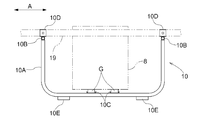
- FIG. 17 is a view showing the first embodiment (hereinafter, the same up to FIG. 16), and is an overall side view of a work vehicle.
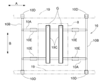
- FIG. 2 is an overall plan view of the work vehicle. It is a top view of a refraction link mechanism. It is a side view of a bending link mechanism. It is a top view showing the left turning state by a turning mechanism.
- FIG. 5 is a plan view showing a right turning state by the turning mechanism. It is a control block diagram. It is a side view at the time of changing the attachment state of an exterior frame. It is a side view at the time of changing the attachment state of an exterior frame.
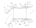
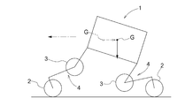
- FIG. 3 is a schematic plan view of the work vehicle in a turning state.
- FIG. 3 is a schematic plan view of the work vehicle in a straight traveling state. It is a schematic side view of a work vehicle in a straight traveling state. It is a side view of a support frame. It is a top view of a support frame. It is a front view of a support frame. It is a control block diagram by 2nd Embodiment.
- FIG. 26 is a view showing the third embodiment (hereinafter the same up to FIG. 25), and is an overall side view of a work vehicle.
- FIG. 2 is an overall plan view of the work vehicle. It is a top view of a refraction link mechanism. It is a side view of a bending link mechanism.
- FIG. 5 is a plan view showing a right turning state by the turning mechanism. It is a side view which shows the flat terrain running state of a working vehicle.
- FIG. 4 is a side view showing a state in which the work vehicle gets over the step.
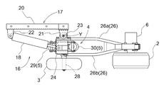
- the longitudinal direction of the vehicle body when defining the longitudinal direction of the vehicle body, it is defined along the vehicle body traveling direction, and when defining the horizontal direction of the vehicle body, the left and right are defined in a state viewed from the aircraft traveling direction. I do. That is, the direction indicated by the reference numeral (A) in FIG. 1 is the vehicle front-rear direction, and the direction indicated by the reference numeral (B) in FIG. 2 is the vehicle left-right direction.
- the work vehicle includes a vehicle body 1 that supports the entire vehicle and has a substantially rectangular shape in plan view, a plurality of (specifically, four) traveling wheels 2, and a plurality of traveling wheels. 2, a plurality of auxiliary wheels 3 provided corresponding to each of the two, a plurality of traveling wheels 2, and a refraction link mechanism 4 (an example of a vehicle body supporting portion) for supporting the plurality of traveling wheels 2 on the vehicle main body 1 so as to be freely repositionable.
- a hydraulically driven attitude change operation means 5 capable of changing the mechanism 4 and a plurality of hydraulic motors 6 for individually driving the plurality of traveling wheels 2 are provided.
- the bending link mechanism 4, the traveling wheel 2, and the auxiliary wheel 3 are provided on each of the front and rear sides of the vehicle body 1, one pair each on the right and left sides.
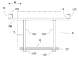
- the vehicle body 1 is provided with a rectangular frame-shaped body frame 7 that supports the whole, a hydraulic supply source 8 that sends out hydraulic oil toward the attitude change operation means 5, and a hydraulic supply source 8 that supplies the hydraulic oil to the attitude change operation means 5. And a valve mechanism 9 for controlling the operating oil.
- the hydraulic supply source 8 includes an engine and a hydraulic pump driven by the engine, and these are integrally connected.
- the hydraulic supply source 8 is mounted and supported by a support frame (support base) 10 connected to the lower side of the vehicle body frame 7, and is provided in a state of being located at the lower abdomen of the vehicle body 1.
- the hydraulic supply source 8 sends out and supplies hydraulic oil to the posture changing operation means 5 via a valve mechanism 9 by a hydraulic pump driven by an engine.
- the hydraulic supply 8 and the support frame 10 are connected and integrally slid laterally from the vehicle body 1 in a connected state.
- the support frame 10 can be detached, and can be mounted by sliding the support frame 10 to the vehicle body frame 7 sideways.
- the support frame 10 includes a pair of left and right bottom receiving members 10A formed by bending a round pipe material into a substantially U shape in side view, and front and rear sides of the bottom receiving member 10A.
- the end portions are connected to each other, and a pair of front and rear lateral support members 10B made of a round pipe material provided so as to extend to both left and right sides are integrally connected to form a frame.
- a pair of front and rear engine supports 10C are placed and connected by bolts over the left and right bottom receiving members 10A.
- connection bracket 10D made of a horizontally open channel material is connected to upper portions of both left and right end portions of the pair of front and rear sideways support members 10B.
- the left and right connection brackets 10D are open in the same direction, and are mounted laterally from one direction on a rectangular tubular front-rear frame 19 provided on both left and right lateral portions of the body frame 7 of the vehicle body 1. It is configured to be connected by bolts.
- a ground support 10E is provided below the pair of bottom receiving members 10A to support the ground receiving member 10A in a non-slip state while being grounded. Therefore, the support frame 10 is configured to be able to hold the posture of the entire vehicle body with the lower end portion in contact with the ground.
- the hydraulic supply source 8 is configured by integrally connecting the engine and a hydraulic pump.
- the hydraulic supply source 8 is mounted and supported by the front and rear engine supports 10C via the vibration-proof rubber G.
- the hydraulic pressure source 8 is provided so as to be housed under the vehicle body frame 7.
- the hydraulic supply source 8 can be slid laterally from the vehicle body 1 and removed.
- the support frame 10 can be slid laterally and attached.
- the valve mechanism 9 is provided in a state of being mounted and supported on the upper side of the body frame 7 and includes a plurality of hydraulic control valves 11 for supplying and discharging hydraulic oil to the attitude changing operation means 5 or adjusting the flow rate.
- the upper part of the valve mechanism 9 is covered by a storage case 12.
- a control device 13 (an example of a control unit) that controls the operation of the valve mechanism 9 is provided above the storage case 12.
- an exterior frame 14 for protecting the valve mechanism 9 stored in the storage case 12, the control device 13 provided above, and the like is provided on the upper side of the body frame 7, for example, when the vehicle body 1 falls down.
- the exterior frame 14 is provided on both front and rear sides, and has a shape in which a rod-like body is bent substantially in a U shape in plan view and is bent in a substantially L shape in side view. Left and right ends are attached and fixed to the ends.
- the front and rear exterior frames 14 are provided such that their upper sides are close to each other, and have a shape that covers the outer peripheral sides of the valve mechanism 9, the control device 13, and the like.
- the front and rear exterior frames 14 are mounted so that the upper side faces outward in the front-rear direction, and a wide mounting plate is mounted above the front and rear exterior frames 14 to be used as a truck for carrying cargo. can do.
- the exterior frame 14 by attaching the exterior frame 14 so that the upper side faces one side in the front-rear direction, the exterior frame 14 can be used as a handle for a worker to grasp by hand.
- a support structure for supporting the traveling wheels 2 on the vehicle body 1 will be described.
- a plurality of (specifically, four) traveling wheels 2 are individually supported on the vehicle body 1 via the refraction link mechanism 4 so as to be vertically movable.
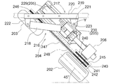
- the bending link mechanism 4 is supported by the vehicle body frame 7 so as to be rotatable around a vertical axis Y through a turning mechanism 16 (an example of turning operation means).
- the turning mechanism 16 is connected to the vehicle body frame 7 and supports the refracting link mechanism 4 in a freely rotatable manner. And a turning hydraulic cylinder (hereinafter, referred to as a turning cylinder) 18 for turning.
- a turning hydraulic cylinder hereinafter, referred to as a turning cylinder
- the vehicle-body-side support portion 17 is provided with a pair of rectangular frame-shaped front-facing frame members 19 provided at the lateral portions of the vehicle body frame 7.
- a connecting member 20 which is fitted and engaged in a state of being sandwiched from one side and is removably bolt-connected, an outer side pivotal support bracket 21 located at an outer side of the connecting member 20 in the vehicle longitudinal direction, and a connecting member 20.
- An inner pivot bracket 22 positioned at an inner location in the vehicle longitudinal direction, and a vertical pivot support shaft 23 supported by the outer pivot bracket 21.
- the refraction link mechanism 4 is rotatably supported around the axis Y.
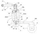
- the refraction link mechanism 4 has a base end 24 supported by the vehicle body-side support portion 17 in a state where the position in the vertical direction is fixed and rotatable around the longitudinal axis Y, and one end of the base end 24.
- a first link 25 rotatably supported around a horizontal axis X1 at a lower portion of the first link 25, and one end supported at the other end of the first link 25 rotatably around a horizontal axis X2 and the other end
- the base end portion 24 is provided in a rectangular frame shape in a plan view, and is rotatable around the vertical axis Y via the rotation support shaft 23 at a position biased inward in the vehicle width direction. In addition, it is supported by the outer-side pivot support bracket 21 of the vehicle-body-side support portion 17.
- the pivot cylinder 18 has one end rotatably connected to the inner pivot bracket 22 and the other end at a position where the base end 24 is displaced laterally with respect to the pivot 23. It is rotatably connected.
- a support shaft 27 provided at one end of the first link 25 is rotatably supported and supported on both left and right sides of the base end 24.
- the first link 25 is supported by a lower portion of the base end 24. 27 are rotatably connected around the axis.
- the first link 25 has a proximal end arm 25b and another end arm 25a. At one end of the first link 25, a base arm 25b extending diagonally upward and outward is integrally formed. The other end of the first link 25 is integrally formed with the other end arm 25a extending diagonally upward and outward.
- the second link 26 includes a pair of left and right band-shaped plate bodies 26a and 26b, and is formed in a forked shape in plan view.
- a connecting portion of the second link 26 to the first link 25 is provided by a pair of plate bodies 26a and 26b.
- a connection support shaft 28 for connecting to the first link 25 is rotatably supported in a region sandwiched between the pair of plate bodies 26a and 26b.
- the traveling wheel 2 is supported at the swing-side end of the second link 26 opposite to the connection point to the first link 25.
- the swing-side end of the second link 26 is formed with an L-shaped extension 26A that extends substantially in an L-shape in a direction away from the vehicle body 1.
- the traveling wheel 2 is supported on the extension side end.
- the traveling wheel 2 is supported in a state where it is located on the outer side of the vehicle body in the left-right direction with respect to the refraction link mechanism 4. More specifically, the second link 26 is supported at the swinging end of the second link 26 so as to be located outside the vehicle body in the left-right direction.
- the hydraulic motor 6 is supported at the swing-side end of the second link 26 in a state of being located on the vehicle body inner side in the left-right direction (opposite to the traveling wheels 2).
- a posture changing operation means 5 is provided corresponding to each of the plurality of refraction link mechanisms 4 and capable of individually changing the posture of the refraction link mechanism 4.
- the posture changing operation means 5 includes a first hydraulic cylinder 29 capable of changing the swing posture of the first link 25 with respect to the vehicle body 1, and a second link 26 with respect to the first link 25.
- a second hydraulic cylinder 30 capable of changing the swinging posture is provided. The first hydraulic cylinder 29 and the second hydraulic cylinder 30 are collectively arranged near the first link 25, respectively.
- the first link 25, the first hydraulic cylinder 29, and the second hydraulic cylinder 30 are disposed in a state where the first link 25, the first hydraulic cylinder 29, and the second hydraulic cylinder 30 are located between the pair of plate bodies 26a, 26b of the second link 26 in plan view.
- the first hydraulic cylinder 29 is provided on the inner side in the vehicle longitudinal direction with respect to the first link 25 and is provided along the longitudinal direction of the first link 25.
- One end of the first hydraulic cylinder 29 is interlockingly connected to a lower portion of the base end 24 via an arcuate first interlocking member 31.
- One end of the first hydraulic cylinder 29 is interlockingly connected to a base end portion of the first link 25 via another second interlocking member 32.
- Both ends of the first interlocking member 31 and the second interlocking member 32 are pivotally connected so as to be relatively rotatable.
- the other end of the first hydraulic cylinder 29 is operatively connected to the other end side arm 25 a formed integrally with the first link 25.
- the second hydraulic cylinder 30 is provided on the opposite side of the first hydraulic cylinder 29, that is, on the outer side in the vehicle longitudinal direction with respect to the first link 25, and substantially along the longitudinal direction of the first link 25. Have been.
- One end of the second hydraulic cylinder 30 is operatively connected to a base arm 25 b formed integrally with the base of the first link 25.
- the other end of the second hydraulic cylinder 30 is interlockingly connected via a third interlocking member 34 to an arm 35 integrally formed at the base end of the second link 26.
- the other end of the second hydraulic cylinder 30 is also interlockingly connected to a swing end side portion of the first link 25 via another fourth interlocking member 36.
- the third interlocking member 34 and the fourth interlocking member 36 are pivotally connected at both side ends so as to be relatively rotatable.
- each of the first link 25, the second link 26, and the traveling wheel 2 is integrated while maintaining the relative posture constant. Specifically, it swings around the horizontal axis X1 at the pivotal connection point with respect to the base end portion 24.
- the second hydraulic cylinder 30 is extended and retracted in a state where the operation of the first hydraulic cylinder 29 is stopped, the second link 26 and the traveling wheel 2 are integrally formed while the posture of the first link 25 is kept constant. It swings around the horizontal axis X2 at the connecting point between the first link 25 and the second link 26.
- the auxiliary wheels 3 are supported by the intermediate bending portions of each of the plurality of bending link mechanisms 4 so as to be freely rotatable.
- the auxiliary wheel 3 is configured by a wheel having substantially the same outer diameter as the traveling wheel 2.
- a connection support shaft 28 that pivotally connects the first link 25 and the second link 26 is formed to extend so as to protrude outward from the second link 26 in the vehicle width direction.
- the auxiliary wheel 3 is rotatably supported at an extended projecting portion of the connection support shaft 28.
- each of the refraction link mechanism 4, the traveling wheel 2, the auxiliary wheel 3, and the posture changing operation means 5 integrally rotates around the axis Y of the rotation support shaft 23. It is freely supported by the outer pivot bracket 21. Then, by expanding and contracting the swivel cylinders 18, they are integrally rotated. From the straight running state in which the traveling wheel 2 faces in the front-rear direction, the turning operation can be performed by about 45 degrees in each of the left turning direction and the right turning direction.
- each of the turning mechanism 16, the bending link mechanism 4, the traveling wheel 2, the auxiliary wheel 3, and the attitude changing operation means 5 is provided. , Can be removed from the vehicle body 1 in a state of being integrally assembled.
- the above-described devices can be attached to the vehicle body 1 in a state of being integrally assembled.
- Hydraulic oil is supplied from the hydraulic supply source 8 to the first hydraulic cylinder 29 and the second hydraulic cylinder 30 of each of the plurality of bending link mechanisms 4 via the valve mechanism 9.
- hydraulic oil is supplied and discharged by the hydraulic control valve 11, and the first hydraulic cylinder 29 and the second hydraulic cylinder 30 can be operated to expand and contract.
- the hydraulic control valve 11 is controlled by the control device 13.
- each of the four second hydraulic cylinders 30 includes a head-side pressure sensor S1 and a cap-side pressure sensor S2.
- the head-side pressure sensor S1 detects the oil pressure in the head-side chamber of the second hydraulic cylinder 30.
- the cap-side pressure sensor S2 detects the oil pressure in the cap-side chamber of the second hydraulic cylinder 30.
- the detection results of the pressure sensors S1 and S2 are input to the control device 13.
- each of the four first hydraulic cylinders 29 and the four second hydraulic cylinders 30 is provided with a stroke sensor S3 capable of detecting the amount of expansion / contraction operation.
- the amount of expansion / contraction operation of each of the hydraulic cylinders 29 and 30 is a detection value corresponding to the swing position of the first link 25 and the second link 26 to be operated, and the stroke sensor S3 corresponds to a position detection sensor.
- the detection result of each stroke sensor S3 is input to the control device 13.
- the mounting positions of the pressure sensors S1 and S2 are not limited to the positions described above. Each of the pressure sensors S1 and S2 only needs to be able to detect (estimate) the oil pressure of the corresponding cap-side chamber or head-side chamber, and may be provided in a pipe from the valve mechanism 9 to the corresponding cap-side chamber or head-side chamber.
- the thrust required to support the vehicle body 1 is calculated based on the detection results of these sensors S1 and S2, and the supply of hydraulic oil to each of the second hydraulic cylinders 30 is controlled based on the calculation result. You.
- the vehicle body 1 is provided with an acceleration sensor S5 including, for example, a triaxial acceleration sensor.
- the front, rear, left and right inclinations of the vehicle body 1 are detected based on the detection result of the acceleration sensor S5, and the attitude of the vehicle body 1 is controlled based on the result. That is, the supply of the hydraulic oil to each of the first hydraulic cylinder 29 and the second hydraulic cylinder 30 is controlled so that the posture of the vehicle body 1 becomes the target posture.
- the traveling wheel 2 is provided with a rotation sensor S6 for detecting the rotation speed of the traveling wheel 2 driven by the hydraulic motor 6.
- Supply of hydraulic oil to the hydraulic motor 6 is controlled based on the rotation speed of the traveling wheel 2 detected by the rotation sensor S6 such that the rotation speed of the traveling wheel 2 becomes a target value.
- the configuration is such that the attitude of the refraction link mechanism 4 is changed by the hydraulic cylinders 29 and 30 as the hydraulically driven attitude change operation means 5, and the traveling drive is also performed by the hydraulic motor 6. Therefore, it is less affected by moisture, fine dust, etc., and is suitable for agricultural work.
- this working vehicle is in a normal traveling mode in a four-wheel traveling state in which all four traveling wheels 2 are in contact with the ground and all four auxiliary wheels 3 are lifted off the ground.
- various traveling modes can be adopted by changing the posture of the bending link mechanism 4 in addition to this mode.
- FIG. 7 shows a control block diagram.
- the control device 13 includes, for example, a microcomputer or the like, and can execute various controls according to a control program. Although not described in detail, the control device 13 controls the posture of the vehicle body 1 based on control information input by manual operation or control information stored in advance according to the work situation at that time. The control is performed so as to bring the state into an appropriate state. Although not shown, the control device 13 also controls the hydraulic oil for the plurality of hydraulic motors 6.
- the control device 13 detects the four first hydraulic cylinders 29 and the four second hydraulic cylinders 30 by the stroke sensors S3 provided in the respective hydraulic cylinders 29, 30.
- the hydraulic control valve 11 is switched so as to operate the hydraulic cylinders 29 and 30 so that the expansion / contraction operation amount detected by the operation becomes the detection value corresponding to the target posture.
- the expansion / contraction operation amount detected by the stroke sensor S3 provided in each hydraulic cylinder 29 is the target.
- Position control is performed to switch the hydraulic control valve 11 to operate each hydraulic cylinder 29 so that the detected value corresponds to the posture.
- the operation of the four second hydraulic cylinders 30 is controlled based on the detection information of the pressure sensors S1 and S2. Specifically, the thrust of the second hydraulic cylinder 30 is calculated based on the detection value of the head-side pressure sensor S1 and the detection value of the cap-side pressure sensor S2. Then, the operation of the second hydraulic cylinder 30 is controlled by switching the hydraulic control valve 11 so that the detected thrust becomes a target value that is set and stored in advance.
- the ground reaction force of the traveling wheels 2 is maintained at an appropriate value.
- the traveling wheels 2 move up and down while following the unevenness of the ground, and each of the traveling wheels 2 maintains an appropriate grounding state without slipping or hindering rotation. It is possible to drive satisfactorily on uneven terrain while supporting the vehicle.
- the control device 13 sets the expansion / contraction operation amount detected by the stroke sensor S3 provided in the turning cylinder 18 to a detection value corresponding to the target turning angle.
- the swing control for operating the swing cylinder 18 by switching the hydraulic control valve 11 is executed.
- the control device 13 controls the left and right traveling wheels 2 located on the front side or the left and right traveling wheels 2 located on the rear side when performing turning control while the work vehicle is moving and traveling.
- the operation of the posture changing operation means 5 is performed so that the center of gravity of the vehicle body 1 moves toward the side opposite to the direction in which the direction changing operation is performed in the vehicle longitudinal direction. Control.
- the control device 13 causes the refraction link mechanism 4 located on the side of the vehicle body front-rear direction on which the direction changing operation is performed to separate the vehicle body 1 from the traveling wheels 2 that are in contact with the ground.
- the posture changing operation means 5 is operated so as to approach the position.
- the turning cylinder 18 when the turning cylinder 18 is operated so that the left and right running wheels 2 on the front side in the vehicle body traveling direction turn leftward as shown in FIG.
- the left and right front hydraulic cylinders of the left and right bending cylinders 4 support the traveling wheels 2 on the front side of the vehicle body so that the base end of the second link 26 swings upward.
- the second hydraulic cylinder 30 is operated. As a result, the vehicle body 1 is switched to the front-back inclined position in which the front side is raised and the rear side is lowered.
- the center of gravity of the vehicle body 1 is directed to the side opposite to the side in which the direction change operation is performed in the vehicle body front-rear direction, as compared with the case where the vehicle is traveling straight. Will move.
- the load of the vehicle body 1 on the front traveling wheel 2 that is turned is received, in other words, the traveling wheel 2 serving as a movement resistance when changing the direction is received from the ground.
- the load can be reduced, and the direction can be changed smoothly.
- the stroke sensor S3 is used as the position detection sensor.
- a rotary potentiometer or the like provided at the swing support point of the first link 25 is used. Is also good.
- the configuration is such that the auxiliary wheel 3 is supported so as to be freely rotatable.
- the configuration may be such that the auxiliary wheel 3 is rotationally driven, or a configuration without such an auxiliary wheel 3 may be provided.
- the traveling wheel 2 is driven by the hydraulic motor 6.
- the power of the engine is supplied to the traveling wheel 2 via a mechanical transmission mechanism such as a chain transmission mechanism. 2 may be provided.
- various configurations may be used, such as a configuration driven by an electric motor, or a configuration in which the power of the engine is separately transmitted to the traveling wheels 2 via a speed change mechanism capable of continuously changing the speed. .
- the support frame 10 is detachably mounted on the vehicle body 1 by detaching or attaching the support frame 10 to the vehicle body frame 7 so that the hydraulic supply 8 is slid laterally.
- a configuration may be adopted in which the hydraulic supply source 8 is slid laterally with respect to the support frame 10 so that the hydraulic supply source 8 can be mounted and detachably supported.
- the support frame 10 is provided with the grounding support 10E that is grounded in a non-slip state.
- the grounding support 10E that is grounded in a non-slip state.
- a plurality of A configuration in which a caster wheel is provided and the grounding support is provided by the caster wheel may be employed.
- the hydraulic supply source 8 includes the engine and the hydraulic pump driven by the engine.
- the hydraulic pump may be driven by an electric motor instead of the engine.
- the attitude changing operation means 5 is configured to include the plurality of hydraulic cylinders 29 and 30, but instead of this configuration, the attitude is changed by providing a hydraulic motor at a pivot point between the links. It may be.
- the bending link mechanism 4 located on the side of the front-rear direction where the direction changing operation is performed separates the vehicle body 1 from the grounded traveling wheel 2 and is located on the opposite side.
- the configuration is such that the attitude changing operation means 5 is operated so that the bending link mechanism 4 moves the vehicle body 1 closer to the traveling wheel 2 that is in contact with the ground, but instead of this configuration, the direction changing operation is performed.
- the center of gravity may be moved by sliding a heavy object provided in the vehicle body 1, for example, an engine or the like, in the vehicle front-rear direction from the vehicle body 1 toward the opposite side.
- the stroke sensor S3 for detecting the amount of expansion / contraction operation of the turning cylinder 18 is provided.
- the rotary sensor provided at the pivot of the first link 25 is used. It is good also as a structure which detects the expansion / contraction operation amount with a potentiometer.
- the turning mechanism 16 (the turning operation means) is provided with the turning cylinder 18, but the turning operation may be performed by an electric motor or a hydraulic motor.
- the auxiliary wheel 3 is configured to be freely rotatable.
- the auxiliary wheel 3 may be configured to be driven to rotate, or may be configured without such an auxiliary wheel 3.
- the traveling wheels 2 are driven by the hydraulic motor 6.
- the power of the engine is supplied to the traveling wheels via a mechanical transmission mechanism such as a chain transmission mechanism. 2 may be provided.
- each of the four first hydraulic cylinders 29 and the four second hydraulic cylinders 30 is provided with a stroke sensor S3 capable of detecting a telescopic operation amount.
- the amount of expansion / contraction operation of each of the hydraulic cylinders 29 and 30 is a detection value corresponding to the swing position of the first link 25 and the second link 26 to be operated, and the detection result of each stroke sensor S3 is input to the control device 13. Is done.
- the vehicle body 1 is provided with an acceleration sensor S5 including, for example, a three-axis acceleration sensor.
- the front, rear, left and right inclinations of the vehicle body 1 are detected based on the detection result of the acceleration sensor S5, and the attitude of the vehicle body 1 is controlled based on the result. That is, the supply of the hydraulic oil to each of the first hydraulic cylinder 29 and the second hydraulic cylinder 30 is controlled so that the posture of the vehicle body 1 becomes the target posture.
- the traveling wheel 2 is provided with a rotation sensor S6 (an example of a driving speed detecting means) for detecting the rotation speed of the traveling wheel 2 driven by the hydraulic motor 6.
- Supply of hydraulic oil to the hydraulic motor 6 is controlled based on the rotation speed of the traveling wheel 2 detected by the rotation sensor S6 such that the rotation speed of the traveling wheel 2 becomes a target value.
- the configuration is such that the attitude of the refraction link mechanism 4 is changed by the hydraulic cylinders 29 and 30 as the hydraulically driven attitude change operation means 5, and the traveling drive is also performed by the hydraulic motor 6. Therefore, it is less affected by moisture, fine dust, etc., and is suitable for agricultural work.
- this working vehicle is in a normal traveling mode in a four-wheel traveling state in which all four traveling wheels 2 are in contact with the ground and all four auxiliary wheels 3 are lifted off the ground.
- various traveling modes can be adopted by changing the posture of the bending link mechanism 4 in addition to this mode.
- FIG. 17 shows a control block diagram.
- the control device 13 includes, for example, a microcomputer or the like, and can execute various controls according to a control program. Then, the control device 13 sets the posture of the vehicle body 1 in an appropriate state according to the work situation at that time based on control information input by manual operation or control information set and stored in advance. And a posture control unit 100 (an example of a control unit) that executes the control so as to perform the control.
- a posture control unit 100 an example of a control unit
- the posture control unit 100 controls each of the four hydraulic cylinders 29 and the four second hydraulic cylinders 30 for each of the hydraulic cylinders 29 in both the state where the traveling vehicle is stopped traveling and the state where the traveling vehicle is traveling. , 30 so that the operation amount of the hydraulic cylinders 29, 30 is switched by switching the hydraulic control valve 11 so that the expansion / contraction operation amount detected by the stroke sensor S3 provided in the stroke sensor S3 becomes a detection value corresponding to the target posture. Execute control.
- the control device 13 adjusts the traveling speed of the vehicle body 1 to an appropriate speed based on control information input by a manual operation or control information set and stored in advance according to the work situation at that time.
- a traveling drive control unit 101 for controlling the plurality of hydraulic motors 6 is provided.
- the traveling drive control unit 101 controls the operation of the hydraulic motor 6 such that the rotation speed of the traveling wheel 2 detected by the rotation sensor S6 becomes a target speed set in advance based on the above-described control information. I do.
- This work vehicle is provided with an idling state detecting means Q for detecting whether or not the traveling wheel 2 is idling, for example, when traveling on uneven terrain having many irregularities.
- the idling state detecting means Q detects a pressure sensor S4 for detecting an internal pressure of the hydraulic oil supply passage in the hydraulic motor 6 and, based on information detected by the pressure sensor S4, when the internal pressure falls below a preset value.
- a determination unit (determination unit 102) that determines that the traveling wheel 2 is in the idling state is configured.
- a pressure sensor S4 for detecting the internal pressure of the hydraulic oil supply passage corresponding to each of the four hydraulic motors 6 is provided. Has been entered. Then, the control device 13 compares the input detection value (internal pressure) of the pressure sensor S4 with a preset setting value, and determines whether the detection value (internal pressure) of any of the pressure sensors S4 is the setting value. When the vehicle speed is lower than the predetermined value, a determination unit 102 (an example of a determination unit) that determines that the corresponding traveling wheel 2 is idling is provided.
- the attitude control unit 100 operates the second hydraulic cylinder 30 so as to lower the corresponding traveling wheel 2, and detects the pressure sensor S4. When the value (internal pressure) returns to or above the set value, the operation of the second hydraulic cylinder 30 is stopped.
- the traveling wheel 2 idles when there is a concave portion on the ground and the traveling wheel 2 is lifted off the ground, or when traveling on a slippery road surface.
- the load pressure on the hydraulic motor 6 is greatly reduced.
- Such a change in the load pressure is detected by the pressure sensor S4, and when the detected value of the pressure sensor S4 falls below the set value, the operation of the second hydraulic cylinder 30 is controlled, so that the traveling wheel 2 is properly driven.
- This is a state in which force is exerted, and the idling state can be eliminated.
- the traveling wheels 2 move up and down while following the unevenness of the ground, and each of the traveling wheels 2 maintains an appropriate grounding state without slipping or hindering rotation. It is possible to drive satisfactorily on uneven terrain while supporting the vehicle.
- the idling state detecting means Q is configured by the pressure sensor S4 and the determination unit 102.
- the following configuration may be employed.
- a rotation sensor S6 (an example of a driving speed detecting unit) for detecting the driving speed of the hydraulic motor 6, a traveling speed detecting unit for detecting the actual traveling speed of the vehicle body 1, and a hydraulic motor detected by the rotation sensor S6.
- the discriminating means for discriminating that the traveling wheel 2 is in the idling state constitutes the idling state detecting means Q. It may be done.
- the traveling speed detecting means for example, an average value of the driving speeds of the four hydraulic motors 6 provided corresponding to the four traveling wheels 2 is obtained, and the traveling speed is obtained from the average value. You may do so.
- a measuring device that can determine the absolute traveling speed of the work vehicle with respect to the ground using a vehicle speed sensor using a millimeter wave radar may be used.
- control device 13 compares the drive speed of one hydraulic motor 6 to be measured with the actual travel speed of the vehicle body 1 measured by the travel speed detection means as described above, and determines that the drive speed is When the traveling speed becomes higher than the actual traveling speed by a set amount or more, a process of determining that the traveling wheel 2 is in the idling state is executed to determine the idling state.
- the ascent / descent support mechanism has been described as being constituted by the bending link mechanism 4 in which two links 25 and 26 are pivotally connected.
- the invention is not limited to the link mechanism, but may be a configuration in which the traveling wheels 2 are supported via a support mechanism having a cylinder structure that can expand and contract with respect to the vehicle body 1 in the vertical direction.
- the posture changing operation means 5 is configured to include the plurality of hydraulic cylinders 29, 30.
- the posture changing operation means 5 includes a hydraulic motor or an electric motor at a pivot point between the links. May be changed.
- the traveling drive device is configured by the hydraulic motor 6, but instead of this configuration, the travel drive device is driven by an electric motor, or the power of the engine can be continuously changed.
- Various configurations may be used, such as a configuration in which each is transmitted to the traveling wheels 2 via a simple transmission mechanism.
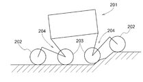
- the work vehicle includes a vehicle body 201 that supports the entire vehicle and is substantially rectangular in plan view, a plurality of (specifically, four) traveling wheels 202, and a plurality of traveling wheels 202.
- a plurality of auxiliary wheels 203 provided corresponding to each of the wheels 202;
- a refraction link mechanism 204 (an example of a lifting support mechanism) for supporting the plurality of traveling wheels 202 on the vehicle main body 201 so as to be individually changeable in position;
- a hydraulically driven attitude change operation means 205 capable of changing the link mechanism 204 and a hydraulic motor 206 (an example of a plurality of travel driving devices) for individually driving the plurality of traveling wheels 202 are provided.
- Each of the refraction link mechanism 204, the traveling wheel 202, and the auxiliary wheel 203 is provided on each of the front and rear sides of the vehicle main body 201, respectively, as a pair of left and right.
- the vehicle body 201 is provided with a rectangular frame-shaped body frame 207 that supports the whole, a hydraulic supply source 208 that sends out hydraulic oil toward the posture changing operation unit 205, and a hydraulic supply source 208 that supplies the hydraulic oil to the posture changing operation unit 205. And a valve mechanism 209 for controlling the operating oil.
- the hydraulic supply source 208 includes an engine and a hydraulic pump driven by the engine, and these are integrally connected.
- the hydraulic supply source 208 is mounted and supported by a support 210 connected to the lower side of the vehicle body frame 207, and is provided in a state of being located at the lower abdomen of the vehicle main body 201.
- the hydraulic supply source 208 sends out and supplies hydraulic oil to the posture changing operation means 205 via a valve mechanism 209 by a hydraulic pump driven by an engine. Then, although not shown, by removing the support base 210 from the body frame 207, the hydraulic supply source 208 and the support base 210 are connected and integrally slid from the vehicle body 201 to the lateral side. It is possible to remove it, and it is possible to slide it to the side and attach it again by attaching the support 210 to the vehicle body frame 207 again.
- the valve mechanism 209 is provided in a state of being mounted and supported on the upper side of the vehicle body frame 207, and includes a plurality of hydraulic control valves 211 for supplying and discharging hydraulic oil to the attitude changing operation means 205 or adjusting the flow rate.
- the upper part of the valve mechanism 209 is covered by the storage case 212.
- a control device 213 for controlling the operation of the valve mechanism 209 is provided above the storage case 212.
- an outer frame 214 for protecting the valve mechanism 209 stored in the storage case 212 and the control device 213 provided above is provided on the upper side of the vehicle body frame 207.
- the exterior frame 214 is provided on both front and rear sides, and has a shape in which a rod-shaped body is bent substantially U-shaped in plan view and is bent substantially L-shaped in side view. Left and right ends are attached and fixed to the ends.
- the front and rear exterior frames 214 are provided such that their upper sides are close to each other, and have a shape that covers the outer peripheral sides of the valve mechanism 209, the control device 213, and the like.
- a support structure for supporting the traveling wheels 202 on the vehicle body 201 will be described.
- a plurality of (specifically, four) traveling wheels 202 are individually supported on the vehicle body 201 via a refraction link mechanism 204 so as to be able to move up and down.
- the bending link mechanism 204 is supported by the vehicle body frame 207 via a turning mechanism 216 so as to be rotatable around a vertical axis Y.
- the turning mechanism 216 is connected to the vehicle body frame 207 and supports the bending link mechanism 204 so as to be rotatable.
- the turning mechanism 216 also includes a turning section 217 for turning the bending link mechanism 204 (see FIGS. 20 and 21).
- Hydraulic cylinder (hereinafter referred to as a swing cylinder) 18 is provided.
- the vehicle-body-side support portion 217 is positioned horizontally with respect to a pair of upper and lower rectangular tubular front-rear frame members 219 provided at the lateral portions of the vehicle body frame 207.
- a connection member 220 that is fitted and engaged in a state of being pinched from the outside and is removably bolted, and an outer side pivotal support bracket 221 that is located on the outer side of the connection member 220 in the vehicle longitudinal direction;
- An inner pivot bracket 222 located at an inner side of the member 220 in the longitudinal direction of the vehicle body, and a vertical pivot shaft 223 supported by the outer pivot bracket 221.
- the refracting link mechanism 204 is rotatably supported around the axis Y of the H.223.
- the bending link mechanism 204 has a base end 224 supported by the vehicle body-side support portion 217 in a state where the position in the vertical direction is fixed and rotatable around the vertical axis Y, and one end of the base end 224.
- a first link 225 rotatably supported around a horizontal axis X1 at a lower portion of the first link 225, and one end portion rotatably supported around the horizontal axis X2 at the other end of the first link 225 and the other end thereof
- a second link 226 on which the traveling wheel 202 is supported.
- the base end portion 224 is provided in a rectangular frame shape in a plan view, and is rotatable around the vertical axis Y via the rotation support shaft 223 at a position deviated inward in the vehicle width direction. In addition, it is supported by the outer side support bracket 221 of the vehicle body side support portion 217.
- the pivot cylinder 218 has one end rotatably connected to the inner pivot bracket 222 and the other end at a position where the base end 224 is laterally displaced from the pivot shaft 223. It is rotatably connected.
- a support shaft 227 provided at one end of the first link 225 is rotatably supported and supported on both left and right sides of the base end 224.
- the first link 225 is supported by a lower portion of the base end 224 with respect to the support shaft. 227 are rotatably connected around the axis.
- the first link 225 has a base end arm 225b and a second end arm 225a. At one end of the first link 225, a base arm 225b extending diagonally upward and outward is integrally formed. The other end side of the first link 225 is integrally formed with the other end side arm portion 225a extending diagonally upward and outward.
- the second link 226 includes a pair of left and right band-shaped plate bodies 226a and 226b, and is formed in a forked shape in plan view.
- a pair of plate bodies 226a and 226b are spaced from each other at the connection point of the second link 226 to the first link 225.
- a connection support shaft 228 for connecting to the first link 225 is rotatably supported in a region sandwiched between the pair of plate members 226a and 226b.
- the traveling wheel 202 is supported at the swing-side end of the second link 226 opposite to the connection point to the first link 225. As shown in FIG.
- the swing-side end of the second link 226 is formed with an L-shaped extension 226 ⁇ / b> A extending substantially in an L-shape in a direction away from the vehicle body 201.
- a traveling wheel 202 is supported on the extension side end.
- the traveling wheel 202 is supported on the refraction link mechanism 204 so as to be located outside the vehicle body in the left-right direction.
- the second link 226 is supported at the swing-side end portion in a state of being located outside the vehicle body in the left-right direction.
- a posture changing operation means 205 is provided for each of the plurality of bending link mechanisms 204, which can change the posture of the bending link mechanism 204 individually.
- the posture changing operation means 205 includes a first hydraulic cylinder 229 capable of changing the swing posture of the first link 225 with respect to the vehicle body 201, and a second link 226 with respect to the first link 225. And a second hydraulic cylinder 230 capable of changing the swinging posture of the second hydraulic cylinder 230.
- the first hydraulic cylinder 229 and the second hydraulic cylinder 230 are respectively arranged collectively near the first link 225.
- the first link 225, the first hydraulic cylinder 229, and the second hydraulic cylinder 230 are provided in a state where they are located between the pair of plate bodies 226a and 226b of the second link 226 in plan view.
- the first hydraulic cylinder 229 is located on the inner side in the vehicle longitudinal direction with respect to the first link 225, and is provided along the longitudinal direction of the first link 225.
- One end of the first hydraulic cylinder 229 is operatively connected to a lower part of the base end 224 via an arc-shaped first interlocking member 231.
- One end of the first hydraulic cylinder 229 is operatively connected to a base end side of the first link 225 via another second interlocking member 232.
- Both ends of the first interlocking member 231 and the second interlocking member 232 are pivotally connected so as to be relatively rotatable.
- the other end of the first hydraulic cylinder 229 is operatively connected to the other end side arm 225 a formed integrally with the first link 225.
- the second hydraulic cylinder 230 is provided on the opposite side of the first hydraulic cylinder 229, that is, on the outer side in the vehicle longitudinal direction with respect to the first link 225, and substantially along the longitudinal direction of the first link 225. Have been. One end of the second hydraulic cylinder 230 is operatively connected to a base arm 225 b formed integrally with the base of the first link 225. The other end of the second hydraulic cylinder 230 is operatively connected to an arm 35 integrally formed at a base end portion of the second link 226 via a third interlocking member 234. The other end of the second hydraulic cylinder 230 is also operatively connected to a swing end side portion of the first link 225 via another fourth interlocking member 236. The third interlocking member 234 and the fourth interlocking member 236 are connected to each other at both ends so as to be relatively rotatable.
- each of the first link 225, the second link 226, and the traveling wheel 202 is integrated while keeping the relative posture constant. Specifically, it swings around the horizontal axis X ⁇ b> 1 at the pivotal connection point to the base end 224.
- the second hydraulic cylinder 230 is expanded and contracted in a state where the operation of the first hydraulic cylinder 229 is stopped, the second link 226 and the traveling wheel 202 are integrally formed while the posture of the first link 225 is maintained constant.
- the first link 225 and the second link 226 swing around the horizontal axis X2 at the connection point.
- Auxiliary wheels 203 are freely rotatably supported by the intermediate bending portions of each of the plurality of bending link mechanisms 204.
- the auxiliary wheel 203 is configured by a wheel having substantially the same outer diameter as the traveling wheel 202.
- a connection support shaft 228 that pivotally connects the first link 225 and the second link 226 is formed to extend outward from the second link 226 in the vehicle width direction.
- An auxiliary wheel 203 is rotatably supported at an extended projecting portion of the connection support shaft 228.
- the hydraulic motor 206 is provided so as to be located between the intermediate bending portion of the bending link mechanism 204, that is, the position where the auxiliary wheel 203 is located, and the support portion of the traveling wheel 202. Specifically, as shown in FIG. 21, the hydraulic motor 206 is provided in a state of being mounted and supported on the upper part of the L-shaped extending portion 226A of the second link 226.
- the hydraulic motor 206 is configured to drive the traveling wheel 202 and the auxiliary wheel 203 of the bending link mechanism 204 provided with the hydraulic motor 206, respectively.
- the power of the hydraulic motor 206 is transmitted to the traveling wheels 202 and the auxiliary wheels 203 via the chain transmission mechanism 240.
- two drive sprockets 242 and 243 are supported on a lateral output shaft 241 of the hydraulic motor 206 so as to be integrally rotatable.
- the first transmission chain 245 is wound around one of the driving sprockets 242 and the driven sprocket 244 supported so as to be integrally rotatable on the rotation support shaft 202A of the traveling wheel 202.
- the second transmission chain 247 is wound around the other drive sprocket 243 of the two drive sprockets 242 and 243 and the driven sprocket 246 supported integrally and rotatably on the rotation support shaft 203A of the auxiliary wheel 203. I have.
- the periphery of the chain transmission mechanism 240 is covered with a case 248 so that weeds, stem stalks and the like are not involved.
- the two drive sprockets 242, 243 have the same diameter and the same number of teeth.
- the two driven sprockets 244 and 246 have the same diameter and the same number of teeth.
- the traveling wheel 202 and the auxiliary wheel 203 have the same outer diameter. Accordingly, the traveling wheel 202 and the auxiliary wheel 203 are synchronously driven at the same rotational speed with the rotational drive of the hydraulic motor 206.
- each of the bending link mechanism 204, the traveling wheel 202, the auxiliary wheel 203, the hydraulic motor 206, the chain transmission mechanism 240, and the attitude changing operation means 205 are integrally rotated.
- the shaft 223 is supported by the outer pivot bracket 221 so as to be rotatable around the axis Y of the shaft 223. Then, by expanding and contracting the swivel cylinders 218, they are integrally rotated. From the straight running state in which the traveling wheel 202 faces in the front-rear direction, the turning operation can be performed by about 45 degrees in each of the left turning direction and the right turning direction.
- auxiliary wheels 203 it is also possible to ground all the auxiliary wheels 203 and run with all running wheels 202 levitated.
- a running mode for example, when the vehicle rides over a step, the vehicle can be brought close to the point of the step, and the traveling wheel 202 and the second link 226 that are lifted upward are put on the step as they are to get over the step.
- the distance between the wheels contacting the ground in the front-rear direction is reduced, so that the vehicle can make a small turn.
- each of the change operation means 205 can be detached from the vehicle main body 201 in a state where they are integrally assembled. Further, by connecting the connecting member 220 to the front-facing frame body 219 by bolts, the above-described devices can be attached to the vehicle main body 201 in a state of being integrally assembled.
- Hydraulic oil is supplied from the hydraulic supply source 208 to the first hydraulic cylinder 229 and the second hydraulic cylinder 230 of each of the plurality of bending link mechanisms 204 via the valve mechanism 209.
- hydraulic oil is supplied and discharged by the hydraulic control valve 211, so that the first hydraulic cylinder 229 and the second hydraulic cylinder 230 can be operated to expand and contract.
- the traveling wheel 202 is provided with a rotation sensor S6 (an example of a driving speed detecting unit) that detects the rotational speed of the traveling wheel 202 driven by the hydraulic motor 206.
- Supply of hydraulic oil to the hydraulic motor 206 is controlled based on the rotation speed of the traveling wheel 202 detected by the rotation sensor S6 such that the rotation speed of the traveling wheel 202 becomes a target value. That is, by adjusting the flow rate of the hydraulic oil by the hydraulic control valve 211 corresponding to the hydraulic motor 206, the rotation speed of the hydraulic motor 206, that is, the traveling wheels 202 and the auxiliary wheels 203 can be changed.
- Each of the four first hydraulic cylinders 229 and the four second hydraulic cylinders 230 is provided with a stroke sensor (not shown) capable of detecting the amount of expansion / contraction operation.
- the vehicle body 201 is provided with an acceleration sensor S5 including, for example, a triaxial acceleration sensor or the like.
- the front, rear, left and right inclinations of the vehicle body 201 are detected based on the detection result of the acceleration sensor S5, and the attitude of the vehicle body 201 is controlled based on the result. That is, supply of hydraulic oil to each of the first hydraulic cylinder 229 and the second hydraulic cylinder 230 is controlled based on the detection result of the stroke sensor so that the posture of the vehicle body 201 becomes the target posture.
- the hydraulic cylinders 229 and 230 and the hydraulic motors 206 are controlled by the control device 213 based on control information input by manual operation or control information set and stored in advance.
- the power of the hydraulic motor 206 as the traveling drive device is transmitted to the traveling wheels 202 and the auxiliary wheels 203 via the chain transmission mechanism 240, but instead of this configuration, the hydraulic motor The power of the motor 206 may be transmitted to the traveling wheels 202 and the auxiliary wheels 203 via a transmission belt, or the power may be transmitted via a gear transmission mechanism in which a plurality of gears are engaged and transmitted. .
- the traveling drive device (the hydraulic motor 206) is provided so as to be located between the intermediate refraction portion of the refraction link mechanism 204 and the support portion of the traveling wheel 202.
- the traveling drive device (the hydraulic motor 206) may be supported on the vehicle body 201 side.
- the traveling drive device is configured by the hydraulic motor 206 that drives the traveling wheel 202 and the auxiliary wheel 203 provided in the corresponding bending link mechanism 204, respectively.
- various configurations may be used, such as a configuration driven by an electric motor, or a configuration in which the power of the engine is separately transmitted to the traveling wheels 202 via a speed change mechanism capable of continuously changing the speed. Is also good.
- the posture changing operation means 205 is configured to include the plurality of hydraulic cylinders 229 and 230. May be changed.
- the refraction link mechanism 204 has a configuration in which the two links 225 and 226 are pivotally connected. Instead of this configuration, the refraction link mechanism 204 may include three or more links.
Landscapes
- Engineering & Computer Science (AREA)
- Mechanical Engineering (AREA)
- Mining & Mineral Resources (AREA)
- Civil Engineering (AREA)
- General Engineering & Computer Science (AREA)
- Structural Engineering (AREA)
- Chemical & Material Sciences (AREA)
- Combustion & Propulsion (AREA)
- Transportation (AREA)
- Vehicle Body Suspensions (AREA)
Priority Applications (3)
| Application Number | Priority Date | Filing Date | Title |
|---|---|---|---|
| EP19824511.0A EP3812250A4 (en) | 2018-06-25 | 2019-06-12 | WORK VEHICLE |
| CN201980031218.4A CN112119004B (zh) | 2018-06-25 | 2019-06-12 | 作业车 |
| US17/047,807 US11498632B2 (en) | 2018-06-25 | 2019-06-12 | Work vehicle |
Applications Claiming Priority (10)
| Application Number | Priority Date | Filing Date | Title |
|---|---|---|---|
| JP2018-119982 | 2018-06-25 | ||
| JP2018-119979 | 2018-06-25 | ||
| JP2018-119981 | 2018-06-25 | ||
| JP2018119981A JP6934455B2 (ja) | 2018-06-25 | 2018-06-25 | 作業車 |
| JP2018119980A JP6899801B2 (ja) | 2018-06-25 | 2018-06-25 | 作業車 |
| JP2018-119978 | 2018-06-25 | ||
| JP2018119982A JP6937725B2 (ja) | 2018-06-25 | 2018-06-25 | 作業車 |
| JP2018119978A JP6899799B2 (ja) | 2018-06-25 | 2018-06-25 | 作業車 |
| JP2018119979A JP6899800B2 (ja) | 2018-06-25 | 2018-06-25 | 作業車 |
| JP2018-119980 | 2018-06-25 |
Publications (1)
| Publication Number | Publication Date |
|---|---|
| WO2020004024A1 true WO2020004024A1 (ja) | 2020-01-02 |
Family
ID=68986420
Family Applications (1)
| Application Number | Title | Priority Date | Filing Date |
|---|---|---|---|
| PCT/JP2019/023212 WO2020004024A1 (ja) | 2018-06-25 | 2019-06-12 | 作業車 |
Country Status (4)
| Country | Link |
|---|---|
| US (1) | US11498632B2 (zh) |
| EP (1) | EP3812250A4 (zh) |
| CN (1) | CN112119004B (zh) |
| WO (1) | WO2020004024A1 (zh) |
Families Citing this family (3)
| Publication number | Priority date | Publication date | Assignee | Title |
|---|---|---|---|---|
| WO2023141656A1 (en) * | 2022-01-24 | 2023-07-27 | Winthrop Dada | Vehicle suspension system with active adjustment of wheel caster angle and ride height |
| CN116373806B (zh) * | 2023-03-24 | 2023-10-17 | 中国水利水电第四工程局有限公司 | 一种建筑运输车爬坡辅助装置 |
| CN116931574A (zh) * | 2023-07-24 | 2023-10-24 | 国广顺能(上海)能源科技有限公司 | 一种车体多模式循迹方法、存储介质及电子设备 |
Citations (5)
| Publication number | Priority date | Publication date | Assignee | Title |
|---|---|---|---|---|
| JPH061157U (ja) * | 1991-06-17 | 1994-01-11 | 三菱重工業株式会社 | 脚・装輪式車両 |
| JPH09501630A (ja) * | 1993-08-19 | 1997-02-18 | デ オリベイラ,フェルナンド ホセ ネリー | 関節付腕に取り付けられる牽引手段を備えた万能地上車に適用されるべきシステム |
| JPH09131679A (ja) * | 1995-11-08 | 1997-05-20 | Eiji Nakano | 走行ロボットの走行制御装置 |
| JPH09142347A (ja) | 1995-11-24 | 1997-06-03 | Mitsubishi Heavy Ind Ltd | 不整地移動装置 |
| JP2007161105A (ja) * | 2005-12-14 | 2007-06-28 | Ihi Aerospace Co Ltd | 走行ロボット |
Family Cites Families (21)
| Publication number | Priority date | Publication date | Assignee | Title |
|---|---|---|---|---|
| US507947A (en) * | 1893-10-31 | vaughn | ||
| JPS55170182U (zh) | 1979-05-24 | 1980-12-06 | ||
| US4558758A (en) | 1983-12-02 | 1985-12-17 | Erwin Littman | Prime mover |
| CA1244061A (en) * | 1984-10-15 | 1988-11-01 | Daniel R. St. Onge | Tuck-a-way tag axle assembly for work vehicle |
| US4931491A (en) * | 1988-11-25 | 1990-06-05 | Savin Roland R | Coating composition exhibiting improved resistance to environmental attack |
| US4932491A (en) * | 1989-03-21 | 1990-06-12 | The United States Of America As Represented By The Administrator Of The National Aeronautics And Space Administration | Body steered rover |
| GB8913809D0 (en) * | 1989-06-15 | 1989-08-02 | Group Lotus | Vehicle suspension system |
| JP3340770B2 (ja) * | 1992-12-02 | 2002-11-05 | 株式会社クボタ | 作業車 |
| US5718443A (en) * | 1995-12-12 | 1998-02-17 | St. Onge; Daniel R. | Longitudinally and vertically adjustable axle assembly |
| KR100599471B1 (ko) * | 2003-11-11 | 2006-07-12 | 현대모비스 주식회사 | 현가 장치의 액추에이터 어셈블리 |
| JP2005212671A (ja) | 2004-01-30 | 2005-08-11 | Mitsuba Corp | パワーアシスト付き搬送装置の制御方法及びパワーアシスト付き搬送装置 |
| WO2007081452A1 (en) * | 2006-01-05 | 2007-07-19 | Scruggs Donald E | Arakodile vehicles |
| DE102007034840A1 (de) * | 2007-07-26 | 2009-01-29 | Dr. Ing. H.C. F. Porsche Aktiengesellschaft | Fahrwerkssystem für ein Kraftfahrzeug und Verfahren zur Fahrdynamikregelung |
| AT507947B1 (de) * | 2009-02-20 | 2011-06-15 | Univ Graz Tech | Modulares roboterfahrwerk |
| AT14540U1 (de) * | 2013-06-13 | 2016-01-15 | Amst Systemtechnik Gmbh | Hochdynamischer selbstfahrender Fahrsimulator sowie Verfahren zur Simulation eines Übergangs von einem unbeschleunigten in einen beschleunigten Zustand |
| CN104401420B (zh) * | 2014-11-02 | 2016-06-29 | 盐城工学院 | 可折叠式车轮机构及其车轮折叠方法 |
| US10308108B2 (en) | 2015-03-30 | 2019-06-04 | Kubota Corporation | Working machine |
| JP6482352B2 (ja) | 2015-03-30 | 2019-03-13 | 株式会社クボタ | 作業機 |
| JP6728804B2 (ja) | 2016-03-15 | 2020-07-22 | 株式会社タダノ | 軌陸車の空転防止装置 |
| JP6902728B2 (ja) * | 2017-09-08 | 2021-07-14 | パナソニックIpマネジメント株式会社 | 移動体 |
| CN112172434B (zh) * | 2020-10-15 | 2021-10-29 | 皖西学院 | 一种空气悬架装置 |
-
2019
- 2019-06-12 US US17/047,807 patent/US11498632B2/en active Active
- 2019-06-12 CN CN201980031218.4A patent/CN112119004B/zh active Active
- 2019-06-12 EP EP19824511.0A patent/EP3812250A4/en active Pending
- 2019-06-12 WO PCT/JP2019/023212 patent/WO2020004024A1/ja unknown
Patent Citations (5)
| Publication number | Priority date | Publication date | Assignee | Title |
|---|---|---|---|---|
| JPH061157U (ja) * | 1991-06-17 | 1994-01-11 | 三菱重工業株式会社 | 脚・装輪式車両 |
| JPH09501630A (ja) * | 1993-08-19 | 1997-02-18 | デ オリベイラ,フェルナンド ホセ ネリー | 関節付腕に取り付けられる牽引手段を備えた万能地上車に適用されるべきシステム |
| JPH09131679A (ja) * | 1995-11-08 | 1997-05-20 | Eiji Nakano | 走行ロボットの走行制御装置 |
| JPH09142347A (ja) | 1995-11-24 | 1997-06-03 | Mitsubishi Heavy Ind Ltd | 不整地移動装置 |
| JP2007161105A (ja) * | 2005-12-14 | 2007-06-28 | Ihi Aerospace Co Ltd | 走行ロボット |
Non-Patent Citations (1)
| Title |
|---|
| See also references of EP3812250A4 |
Also Published As
| Publication number | Publication date |
|---|---|
| US11498632B2 (en) | 2022-11-15 |
| EP3812250A1 (en) | 2021-04-28 |
| CN112119004A (zh) | 2020-12-22 |
| CN112119004B (zh) | 2023-01-31 |
| EP3812250A4 (en) | 2022-07-13 |
| US20210163089A1 (en) | 2021-06-03 |
Similar Documents
| Publication | Publication Date | Title |
|---|---|---|
| US11524735B2 (en) | Work vehicle | |
| WO2020004024A1 (ja) | 作業車 | |
| CN111247055B (zh) | 作业车 | |
| CN110494349B (zh) | 作业车 | |
| CN111247057B (zh) | 作业车 | |
| JP6745750B2 (ja) | 作業車 | |
| JP6758278B2 (ja) | 作業車 | |
| US11040589B2 (en) | Work vehicle | |
| KR20180086001A (ko) | 자율적으로 수평을 유지하는 이동 플랫폼 | |
| JP6899801B2 (ja) | 作業車 | |
| JP6843040B2 (ja) | 作業車 | |
| JP6899799B2 (ja) | 作業車 | |
| JP7117989B2 (ja) | 作業車 | |
| JP6758277B2 (ja) | 作業車 | |
| JP6937725B2 (ja) | 作業車 | |
| JP6739387B2 (ja) | 作業車 | |
| JP6899800B2 (ja) | 作業車 | |
| JP6765294B2 (ja) | 油圧ロボット | |
| JP6934455B2 (ja) | 作業車 | |
| JP6701112B2 (ja) | 作業車 | |
| JP6701111B2 (ja) | 作業車 | |
| JP7450525B2 (ja) | 作業車 | |
| JP2023092156A (ja) | 作業車 | |
| JPS61280205A (ja) | 田植機のロ−リング制御装置 | |
| JPH03151810A (ja) | コンバイン等の走行制御装置 |
Legal Events
| Date | Code | Title | Description |
|---|---|---|---|
| 121 | Ep: the epo has been informed by wipo that ep was designated in this application |
Ref document number: 19824511 Country of ref document: EP Kind code of ref document: A1 |
|
| NENP | Non-entry into the national phase |
Ref country code: DE |
|
| ENP | Entry into the national phase |
Ref document number: 2019824511 Country of ref document: EP Effective date: 20210125 |