WO2020003867A1 - 飛沫感染抑制システム、及び、飛沫感染抑制方法 - Google Patents
飛沫感染抑制システム、及び、飛沫感染抑制方法 Download PDFInfo
- Publication number
- WO2020003867A1 WO2020003867A1 PCT/JP2019/021282 JP2019021282W WO2020003867A1 WO 2020003867 A1 WO2020003867 A1 WO 2020003867A1 JP 2019021282 W JP2019021282 W JP 2019021282W WO 2020003867 A1 WO2020003867 A1 WO 2020003867A1
- Authority
- WO
- WIPO (PCT)
- Prior art keywords
- airflow
- person
- region
- regions
- detection unit
- Prior art date
Links
Images


Classifications
-
- F—MECHANICAL ENGINEERING; LIGHTING; HEATING; WEAPONS; BLASTING
- F24—HEATING; RANGES; VENTILATING
- F24F—AIR-CONDITIONING; AIR-HUMIDIFICATION; VENTILATION; USE OF AIR CURRENTS FOR SCREENING
- F24F9/00—Use of air currents for screening, e.g. air curtains
-
- A—HUMAN NECESSITIES
- A61—MEDICAL OR VETERINARY SCIENCE; HYGIENE
- A61G—TRANSPORT, PERSONAL CONVEYANCES, OR ACCOMMODATION SPECIALLY ADAPTED FOR PATIENTS OR DISABLED PERSONS; OPERATING TABLES OR CHAIRS; CHAIRS FOR DENTISTRY; FUNERAL DEVICES
- A61G10/00—Treatment rooms or enclosures for medical purposes
-
- F—MECHANICAL ENGINEERING; LIGHTING; HEATING; WEAPONS; BLASTING
- F24—HEATING; RANGES; VENTILATING
- F24F—AIR-CONDITIONING; AIR-HUMIDIFICATION; VENTILATION; USE OF AIR CURRENTS FOR SCREENING
- F24F11/00—Control or safety arrangements
- F24F11/70—Control systems characterised by their outputs; Constructional details thereof
- F24F11/72—Control systems characterised by their outputs; Constructional details thereof for controlling the supply of treated air, e.g. its pressure
- F24F11/79—Control systems characterised by their outputs; Constructional details thereof for controlling the supply of treated air, e.g. its pressure for controlling the direction of the supplied air
-
- F—MECHANICAL ENGINEERING; LIGHTING; HEATING; WEAPONS; BLASTING
- F24—HEATING; RANGES; VENTILATING
- F24F—AIR-CONDITIONING; AIR-HUMIDIFICATION; VENTILATION; USE OF AIR CURRENTS FOR SCREENING
- F24F2120/00—Control inputs relating to users or occupants
- F24F2120/10—Occupancy
-
- F—MECHANICAL ENGINEERING; LIGHTING; HEATING; WEAPONS; BLASTING
- F24—HEATING; RANGES; VENTILATING
- F24F—AIR-CONDITIONING; AIR-HUMIDIFICATION; VENTILATION; USE OF AIR CURRENTS FOR SCREENING
- F24F2120/00—Control inputs relating to users or occupants
- F24F2120/10—Occupancy
- F24F2120/12—Position of occupants
-
- F—MECHANICAL ENGINEERING; LIGHTING; HEATING; WEAPONS; BLASTING
- F24—HEATING; RANGES; VENTILATING
- F24F—AIR-CONDITIONING; AIR-HUMIDIFICATION; VENTILATION; USE OF AIR CURRENTS FOR SCREENING
- F24F2120/00—Control inputs relating to users or occupants
- F24F2120/10—Occupancy
- F24F2120/14—Activity of occupants
-
- F—MECHANICAL ENGINEERING; LIGHTING; HEATING; WEAPONS; BLASTING
- F24—HEATING; RANGES; VENTILATING
- F24F—AIR-CONDITIONING; AIR-HUMIDIFICATION; VENTILATION; USE OF AIR CURRENTS FOR SCREENING
- F24F2120/00—Control inputs relating to users or occupants
- F24F2120/20—Feedback from users
-
- F—MECHANICAL ENGINEERING; LIGHTING; HEATING; WEAPONS; BLASTING
- F24—HEATING; RANGES; VENTILATING
- F24F—AIR-CONDITIONING; AIR-HUMIDIFICATION; VENTILATION; USE OF AIR CURRENTS FOR SCREENING
- F24F2221/00—Details or features not otherwise provided for
- F24F2221/10—Details or features not otherwise provided for combined with, or integrated in, furniture
Definitions
- the present disclosure relates to a droplet infection suppression system and a droplet infection suppression method for suppressing infection of an infectious disease.
- droplet infection or airborne infection is generally considered to be the major route of infection. Therefore, if there is an infected person in a certain group of susceptible persons, susceptible persons exposed to the infected person's cough or sneeze will be infected or susceptible persons who have inhaled the influenza virus etc. contained in the breath of the infected person. Can be infected and in some cases outbreaks can occur.
- Non-Patent Document 1 discloses the results of a numerical simulation of how droplets fly when an infected person coughs or sneezes when the room is ventilated. According to this result, when a person coughs or sneezes at an initial speed of 10 m / s, the person reaches the susceptor 1 m away in about 5 seconds, and the susceptor is exposed to the cough or sneeze of the infected person. Therefore, in order to prevent droplet infection, it is necessary to protect the recipient from the droplets of the infected person within a very short time of 10 seconds or less.
- Patent Document 1 discloses a technique for preventing droplet infection when a doctor diagnoses a patient.
- a doctor is surrounded by a clean booth, and an airflow is generated from the clean booth.
- the doctor can be prevented from being exposed to the patient's cough.
- Patent Document 2 discloses a desk with an air purifier for the purpose of purifying contaminated air or preventing passive smoking of cigarettes.
- an air outlet, a suction port, and a dust filter are provided near the center of the desk, and an air flow is blown over a wide range at a solid angle of about 180 ° from the air outlet, so that the air flow in the entire room is provided. Circulates greatly, and can efficiently purify the contaminated air, and quickly diffuse smoke throughout the room, thereby preventing passive smoking.
- JP 2010-117048 A Japanese Utility Model Publication No. 3-13827
- Patent Document 1 is difficult to apply when the infected person is not known in advance.
- Patent Document 2 does not disclose a technique for suppressing droplet infection.
- the present disclosure has been made in view of the above-described circumstances, and provides a technique capable of appropriately suppressing droplet infection due to coughing or sneezing of an infected person.
- a droplet infection suppression system includes an airflow generation unit that generates an airflow for separating a space into a plurality of first regions, and a first detection that detects a person for each of the plurality of first regions.
- Unit a second detection unit that detects a cough or sneeze in the space, and a first region where a person detected by the first detection unit is present when the second detection unit detects the cough or sneeze.
- a control unit configured to cause the airflow generation unit to generate an airflow that separates a second region including the one or more first regions from another region.
- the computer-readable recording medium includes, for example, a non-volatile recording medium such as a CD-ROM (Compact Disc-Read Only Memory).
- droplet infection due to coughing or sneezing of an infected person can be appropriately suppressed.
- FIG. 1 is a diagram showing a schematic configuration of a droplet infection suppression system according to Embodiment 1.
- FIG. 2 is a block diagram illustrating a functional configuration of the droplet infection suppression system according to the first embodiment.
- FIG. 3 is a flowchart showing an example of the operation of the droplet infection suppression system according to the first embodiment.
- FIG. 4 is a diagram illustrating an example of separation by airflow when the droplet infection suppression system according to Embodiment 1 detects a cough or a sneeze.
- FIG. 5 is a diagram showing another example of separation by airflow when the droplet infection suppression system according to Embodiment 1 detects a cough or a sneeze.
- FIG. 1 is a diagram showing a schematic configuration of a droplet infection suppression system according to Embodiment 1.
- FIG. 2 is a block diagram illustrating a functional configuration of the droplet infection suppression system according to the first embodiment.
- FIG. 3 is a flowchart showing an example of the operation of the
- FIG. 6 is a diagram illustrating another example of separation by airflow when the droplet infection suppression system according to Embodiment 1 detects a cough or a sneeze.
- FIG. 7 is a diagram illustrating an example of separation by airflow when the droplet infection suppression system according to Embodiment 2 detects a cough or a sneeze.
- FIG. 8 is a diagram showing another example of separation by airflow when the droplet infection suppression system according to Embodiment 2 detects a cough or a sneeze.
- influenza is the main route of transmission, mainly by droplet and airborne infections, so it is an important countermeasure to prevent exposure of infected persons to coughing or sneezing.
- Patent Document 1 it is difficult to apply when an infected person is not specified in advance.
- the system is large, requiring a clean booth.
- it can be used as a technology to protect specific people such as doctors from droplet infection, for example, when there are many elderly people at the same time, such as a community room in a nursing care facility, cost and equipment It is not realistic given its size.
- Patent Document 2 does not disclose suppression of droplet infection.
- the purpose is to efficiently purify the contaminated air, it is necessary to circulate the air flow throughout the room, and the flow rate required for this is a large flow rate. Inevitably, the system itself becomes large-scale.
- the inventor of the present application has conducted intensive studies on appropriately preventing the susceptible person from droplet infection.
- the present inventors have found that the above problem can be solved by detecting a cough or sneeze and generating an airflow according to a position of a person present in a space (for example, an indoor room or the like) in which the droplet infection suppression system is provided.
- a space for example, an indoor room or the like
- a droplet infection suppression system includes an airflow generation unit that generates an airflow for separating a space into a plurality of first regions, and a first detection that detects a person for each of the plurality of first regions.
- Unit a second detection unit that detects a cough or sneeze in the space, and a first region where a person detected by the first detection unit is present when the second detection unit detects the cough or sneeze.
- a control unit configured to cause the airflow generation unit to generate an airflow that separates a second region including the one or more first regions from another region.
- the control unit generates an airflow when detecting a cough or sneeze, so that even if the infected person is not known in advance, droplets of the infected person due to the cough or sneeze by another person may be generated. Can be suppressed. That is, infection to other people by coughing or sneezing can be suppressed.
- the control unit may generate an airflow that separates the second region including the first region where the person is located, from the airflow generation unit. That is, the control unit may generate a local airflow that separates the second region from another region from the airflow generation unit that can generate the airflow that separates the plurality of first regions.
- the droplet infection suppression system can suppress the droplet infection by generating a local airflow. Therefore, the droplet infection suppression system according to the present embodiment can appropriately suppress droplet infection due to coughing or sneezing of an infected person. Furthermore, since the droplet infection suppression system only needs to be able to generate a local airflow at the airflow generation unit, it is possible to reduce power consumption while suppressing an increase in the size of the device itself and at the same time as generating airflow from the entire airflow generation unit. Can be reduced.
- the control unit When the first detection unit detects a person in two or more first regions of the plurality of first regions, the control unit generates an airflow that separates the two or more first regions from each other. Generated in the part.
- the second detection unit may be configured to detect the cough or sneeze in the two or more first regions when the first detection unit detects a person in two or more first regions of the plurality of first regions.
- the control section detects the first area where the cough or the sneeze person detected by the second detection section is located from the other area. An airflow to be separated is generated in the airflow generation unit.
- a desk is further provided, and the airflow generating unit is provided on the desk, and generates an airflow upward from the desk.
- the shape of the airflow generating portion is a lattice shape in plan view of the desk.
- the second detection unit is provided on the desk.
- the second detection unit has a microphone or a camera.
- the detection unit can be realized by a generally used microphone or camera. Therefore, the versatility of the droplet infection control system can be improved.
- a chair is further provided, and the first detection unit is provided on the chair.
- the first detecting section has an infrared sensor or a pressure sensor.
- a human detection unit can be realized by a generally used infrared sensor or pressure sensor. Therefore, the versatility of the droplet infection control system can be improved.
- the method for suppressing droplet infection is a step of detecting a person for each of the plurality of first regions, a step of detecting a cough or sneezing, and when the cough or sneezing is detected, Generating an airflow that separates a second region including one or more first regions including the detected first region from another region in the airflow generation unit.
- non-transitory recording medium such as a system, an apparatus, a method, an integrated circuit, a computer program, or a computer-readable CD-ROM.
- An apparatus, a method, an integrated circuit, a computer program, and a recording medium may be realized by a non-transitory recording medium such as a system, an apparatus, a method, an integrated circuit, a computer program, or a computer-readable CD-ROM.
- the terms “above” and “below” refer to an upward direction (vertically upward) and a downward direction (vertically downward) in absolute spatial recognition.
- “upper” and “lower” are expressions that include not only completely coincident with “vertical upper” and “vertical lower” but also substantially in the same direction. For example, “above” and “vertically above” may include an error of about several percent.
- the X axis, the Y axis, and the Z axis indicate three axes of a three-dimensional rectangular coordinate system.
- the X-axis direction and the Y-axis direction are directions parallel to the installation surface on which the airflow generating unit is provided
- the Z-axis direction is a direction perpendicular to the installation surface.
- plane view means a case where the droplet infection suppression system is viewed along a direction perpendicular to the installation surface.
- a term indicating a relationship between elements such as parallel, and a term indicating a shape of an element such as a rectangle, and a numerical value, and a numerical range are not expressions expressing a strict meaning, This is an expression that means that a substantially equivalent range, for example, a difference of about several percent is included.
- infection refers to the invasion of microorganisms such as viruses and bacteria into a living body, and the owner of the living body is also described as an infected person.
- the owner of a living body that is not invaded by microorganisms that is, the owner of a living body that is not infected is also described as a subject.
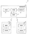
- FIG. 1 is a diagram showing a schematic configuration of a droplet infection control system 10 according to the present embodiment.
- FIG. 2 is a block diagram showing a functional configuration of the droplet infection suppression system 10 according to the present embodiment.
- the droplet infection control system 10 includes a droplet infection control desk 20 (hereinafter, also referred to as a desk 20) and a chair 30.
- the desk 20 and the chair 30 are installed in the space R.
- the space R is a space where a plurality of people h, such as a community room of a care facility, a meeting room of a company, and a restaurant, gather, sit on a chair 30, and communicate at a desk 20.
- the space R may be, for example, a space (for example, a closed space) in a moving body (vehicle, airplane, or the like) on which the person h rides. Further, the space R may be an outdoor space.
- the number of the desks 20 and the chairs 30 included in the droplet infection control system 10 is not particularly limited.
- the droplet infection control system 10 may not include at least one of the desk 20 and the chair 30.
- the droplet infection suppression system 10 may include only the chair 30 of the desk 20 and the chair 30.
- the person h is a person existing in the space R, and may be a person entering the space R for the purpose of, for example, having a conversation in a community room or the like. In the present embodiment, basically, it is not determined whether the person h is infected with an infectious disease. When a person h is infected with an infectious disease, there is a period during which the person has infectivity and a period during which symptoms develop, and the two periods are usually different. If symptoms appear and the body temperature rises, it is known that the person is infected, but in actuality, the infected person becomes contagious much earlier.
- the control method of the droplet infection suppression system 10 may be changed in consideration of the information. . More specifically, the droplet infection control system 10 may be operated only when the infected person coughs or sneezes.
- the droplet infection control system 10 may be operated only when the infected person coughs or sneezes.
- the desk 20 is, for example, a desk used when a person h performs communication or the like, but the use of the desk 20 is not limited thereto, and may be a work table for performing work. If people h gather around it, it may be a desk used for other uses.
- the desk 20 includes a main body 21, a detection unit 24, a control unit 25, an airflow generation unit 26, and a communication unit 27, as shown in FIGS.
- the number of the detection units 24 included in the droplet infection suppression system 10 is, for example, one.
- the main body 21 is the main body of the desk 20 and has a top plate 22 and support legs 23.
- the detection unit 24 and the airflow generation unit 26 may be embedded in the main body 21.
- the top plate 22 is a plate-shaped member for the person h to spread documents and the like.
- the top plate 22 may be, for example, a flat plate shape or a curved plate shape.
- the shape of the top plate 22 in plan view is not particularly limited, and may be a rectangular shape, a circular shape, or a polygonal shape.
- the material of the top plate 22 is not particularly limited, and can be appropriately selected from wood, metal, resin, and the like.
- the support leg 23 extends downward from the top plate 22 and is a leg portion for supporting the top plate 22.
- the shape of the support leg 23 is not particularly limited, and may be any shape as long as the desk 20 can be stably arranged on an installation surface (for example, a floor).
- the number of the support legs 23 is not particularly limited, and may be a plurality.
- the material of the support leg 23 is not particularly limited, and may be appropriately selected from wood, metal, resin, and the like.
- the detection unit 24 detects the cough or sneeze of the person h in the space R. In the present embodiment, the detection unit 24 continuously detects both cough and sneeze. The detection unit 24 detects, for example, a cough and a sneeze of the person h sitting on the chair 30 in the space R. The detection unit 24 outputs the detection result to the control unit 25.
- the detection unit 24 is an example of a second detection unit.
- the detection unit 24 may be configured to include, for example, a sound collection device (for example, a microphone).
- the detection unit 24 detects that the person h has coughed or sneezed, for example, by voice detection using a microphone.
- the detection unit 24 can determine whether or not coughing or sneezing by analyzing the spectrum of the voice acquired by the microphone.
- a threshold of the loudness (dB) may be provided.
- the detection unit 24 can selectively detect a cough or a sneeze of the seated person h by determining that the spectrum equal to or smaller than the threshold is not a detection target.
- the detection unit 24 may include an imaging device (for example, a camera).
- the detection unit 24 may detect a cough or a sneeze by performing image processing and analyzing an image captured by the imaging device. In this case, for example, it is possible to easily classify whether or not the motion pattern obtained by the image processing is cough or sneeze by a classification algorithm such as machine learning. Further, the detection unit 24 may be configured by a combination of a sound collection device and an imaging device.
- the detection unit 24 may be incorporated as a part of the desk 20, for example.
- a communication unit for communication between the desk 20 and the detection unit 24 can be omitted.
- the detection unit 24 can be arranged near the place where the cough or sneeze occurs, the cough or sneeze of the person h communicating with the desk 20 can be detected with high accuracy.
- a small microphone may be embedded in the desk 20.
- the detection unit 24 is not limited to being provided on the desk 20.
- the detection unit 24 may be installed at a position where cough and sneeze can be detected in the space R where the desk 20 is installed. In this case, when detecting the cough or sneeze, the detection unit 24 outputs a detection flag indicating that the cough or sneeze has been detected to the desk 20.
- the desk 20 acquires the detection flag via the communication unit 27.
- the detection unit 24 may include a memory that stores the detected information.
- the control unit 25 is a control device that controls each component of the desk 20.
- the control unit 25 controls the airflow generation unit 26 to generate a predetermined airflow based on, for example, a detection result of cough and sneezing by the detection unit 24 and a detection result of a person obtained from the chair 30.
- the control unit 25 generates a local airflow upward from the airflow generation unit 26.
- the control unit 25 causes the airflow generation unit 26 to generate an airflow that separates the area where the person h detected by the human detection unit 31 is located from other areas.
- the control unit 25 may have a real-time clock function for measuring the current date and time.
- the wind speed of the airflow generated by the control unit 25 in the airflow generation unit 26 will be described with reference to FIG.
- the wind speed of the airflow generated by the control unit 25 in the airflow generation unit 26 is determined by, for example, the size of the desk 20 and the distance between the airflow generation unit 26 and the vicinity of the mouth of the person h in the Z-axis direction and the horizontal direction. You. As shown in FIG. 1, when the person h on the left side coughs or sneezes toward the person h facing him, the droplets s due to the cough or sneeze fall before passing over the airflow generating unit 26. It is necessary to generate an airflow 26a reaching the height of the air.
- the control unit 25 generates an airflow 26a having a wind speed that reaches the height at which the droplet s passes within the time until the droplet s passes through the airflow generation unit 26.
- the wind speed of the airflow 26a controlled by the control unit 25 is, for example, several m / s.
- the speed of the droplets s by coughing or sneezing may be, for example, 10 m / s.
- the height at which the droplets s pass may be calculated, for example, from the average height or the like of the attributes (such as children or adults) of the person using the space R in which the droplet infection suppression system 10 is installed.
- the wind speed of the airflow 26a may be set in consideration of a time lag from when the detection unit 24 detects a cough or a sneeze to when the airflow generation unit 26 generates the airflow 26a. That is, the wind speed may be set based on the time until the droplet s passes through the airflow generation unit 26, the height of the droplet s, and the time lag. This makes it possible to more reliably suppress the droplet s from reaching the person h facing the user.
- the airflow generation unit 26 is an apparatus that can generate an airflow that separates a space in which the droplet infection suppression system 10 is installed into a plurality of regions (a first region A1 illustrated in FIG. 4 described below).
- the airflow generation unit 26 can separate the space on the object (the desk 20 in the present embodiment) on which the airflow generation unit 26 is installed into a plurality of regions.
- the airflow generation unit 26 is a predetermined region (a region including one or more regions among the plurality of regions) under the control of the control unit 25, and a second region illustrated in FIG. A2) is generated to separate the airflow from other areas.
- separation means that an airflow is generated between two different regions (for example, two different second regions A2) to block the flow of air between the two regions.
- separation means that, for example, a wall is formed between two different regions due to the flow of the air current up to the position of the droplet s, thereby interrupting the flow of air between the regions.
- separating a person means, for example, that when a person is present in two different areas (for example, two different second areas A2), an airflow is generated between the two areas, Means to block the flow of air between the areas where there is.
- the airflow generation unit 26 can use a device that generates an airflow such as a DC (Direct Current) fan.
- a DC Direct Current
- the airflow generation unit 26 is a device that generates a planar airflow such as an air curtain.
- air curtain refers to a concept similar to the term “air curtain”, which is generally used.It does not refer to a particular concept, but forms a kind of wall-like state due to the flow of air. Show what you do. That is, the air curtain according to the present embodiment has a function of blocking the flow of air.
- the airflow generating section 26 is different from an air conditioner having a function of blowing air to circulate or mix air so as to efficiently transmit a temperature mainly for a temperature adjusting function.
- the airflow generating unit 26 may be provided at an intermediate position between the facing persons h (in FIG. 1, an intermediate position in the X-axis direction between the two facing persons h). Thereby, even if the person h facing the person coughs or sneezes, the droplet infection can be suppressed to the same extent.
- the communication unit 27 acquires a signal indicating that the person h has been detected from the chair 30.
- the communication unit 27 includes a communication circuit.
- the desk 20 includes the detection unit 24 and the human detection unit 31, the communication unit 27 may not be provided.
- the communication unit 27 When the communication unit 27 is a wireless communication circuit, the communication unit 27 receives a signal transmitted from the chair 30, and obtains a relative positional relationship between the chair 30 and the desk 20 based on the direction and intensity of the transmitted signal. be able to. That is, it is possible to detect which chair 30 the person h is sitting on.
- the desk 20 may include a plurality of communication units 27 from the viewpoint of accurately detecting the relative positional relationship between the desk 20 and the chair 30.
- the chair 30 is a chair on which the person h sits, and is arranged around the desk 20. As shown in FIGS. 1 and 2, the chair 30 includes a person detection unit 31 and a communication unit 32.
- the person detection unit 31 detects whether the person h is sitting on the chair 30.
- the human detection unit 31 is realized by, for example, an infrared sensor or a pressure sensor embedded in the chair 30. Thus, the person h can be easily detected, and the implementation of the system becomes easier.
- the human detection unit 31 is provided on the chair 30, the human detection unit 31 is provided for each of the plurality of chairs 30. This makes it possible to easily determine where a person exists (is sitting) when many people simultaneously communicate, such as a community room in a care facility and a meeting room in an office.
- the human detection section 31 may not be provided on the chair 30.
- the human detection unit 31 may be installed, for example, outside the chair 30.
- the human detection unit 31 may be installed on the desk 20, for example.
- the person detection unit 31 may be an imaging device, or may be an acquisition unit that detects a person by acquiring a signal from a wearable sensor such as a tag worn by the person h.
- the human detection unit 31 is an example of a first detection unit.
- the communication unit 32 When the person detecting unit 31 detects the person h, the communication unit 32 outputs a signal indicating that the person h has been detected to the desk 20.
- the communication unit 32 may continue to output the signal while the person detection unit 31 is detecting the person h, or may output a signal indicating the start and end of the detection of the person h.
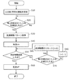
- FIG. 3 is a flowchart showing an example of the operation of the droplet infection suppression system 10 according to the present embodiment.
- each component of the droplet infection control system 10 is assumed to be turned on.
- the desk 20 first obtains information on the presence / absence of a person from the chair 30 (S10).
- the control unit 25 acquires information on the presence / absence of a person from each of the plurality of chairs 30 via the communication unit 27.
- the control unit 25 acquires information on the presence / absence of a person, for example, by acquiring information indicating that the person detection unit 31 included in the chair 30 has detected a person from the chair 30.
- the person detection unit 31 detects a person for each of the plurality of chairs 30.
- the control unit 25 can detect which chair 30 the person h is sitting on.
- the control unit 25 can detect which chair 30 each of the plurality of people h is sitting on from the detection result of the person detection unit 31. That is, the control unit 25 can detect which chair 30 the person h who is prevented from coughing or sneezing is sitting.
- Step S10 is an example of a step of detecting a person in each of the plurality of first areas A1.
- the detection unit 24 determines whether the first cough or sneeze has been detected (S20).
- the control unit 25 acquires a detection result of the detection unit 24 (for example, a microphone embedded in the desk 20).
- a detection result of the detection unit 24 for example, a microphone embedded in the desk 20.
- Step S20 is an example of a step of detecting a cough or a sneeze.
- the control unit 25 calculates an airflow control pattern according to the position of the person h (S30).
- the control unit 25 calculates an airflow pattern that separates the person h in order to prevent the seated person h from being exposed to the droplet infection. Since the control unit 25 does not detect who coughed or sneezed among the plurality of persons h, the control unit 25 calculates an airflow pattern for generating the airflow 26a separating each of the plurality of persons h. Specifically, the control unit 25 calculates an airflow pattern that generates an airflow 26a for separating an area where a plurality of persons h are present.
- control unit 25 causes the airflow generation unit 26 to turn on the airflow 26a based on the calculated airflow pattern (S40). That is, the control unit 25 causes the airflow generation unit 26 to start generating the airflow 26a. In the present embodiment, the control unit 25 causes the airflow generation unit 26 to generate an airflow 26a upward. Note that the control unit 25 causes the airflow generation unit 26 to generate the airflow 26a and starts measuring the elapsed time during which the airflow 26a is being generated.
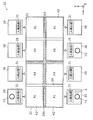
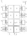
- FIG. 4 is a diagram showing an example of separation by airflow when the droplet infection suppression system 10 according to the present embodiment detects a cough or a sneeze.
- FIG. 4 is a diagram when the desk 20 is viewed in plan.
- FIG. 4 shows an example in which the airflow generating section 26 is provided on the top plate 22 of the desk 20 in a lattice shape.
- the airflow generation part 26 is formed to extend in a direction parallel to the longitudinal direction and the lateral direction of the desk 20, for example.
- the airflow generation unit 26 is provided so as to generate an airflow that separates the space on the desk 20 into eight first regions A1.
- the airflow generation unit 26 may be provided such that the areas of the plurality of first regions A1 separated by the airflow generation unit 26 are equal to each other.
- the droplet infection control system 10 includes eight chairs 30 and three of them are seated by a person.
- the width d of the airflow generation unit 26 is determined by, for example, the size of the assumed droplet s.
- the width d of the airflow generation unit 26 is, for example, about 1 cm.
- the dot hatching in FIG. 4 indicates a portion of the airflow generation unit 26 that is generating an airflow.
- the airflow generating section 26 is not limited to the lattice shape as long as the airflow generating section 26 does not impair the function of the desk 20.
- the airflow generation unit 26 is provided on the entire surface of the top plate 22 to prevent, for example, documents on the desk 20 from flying by the airflow. I can't.
- the control unit 25 acquires information indicating that three persons h1 to h3 are seated at the positions shown in FIG. 4 in step S10. And suppose that person h1 coughed or sneezed. That is, in the case of FIG. 4, the person h1 is the infected person, and the people h2 and h3 are the recipients.
- the control unit 25 calculates an airflow pattern for generating an airflow for separating the people h1 to h3, and generates an airflow 26b according to the airflow pattern. Generated by the unit 26.
- the control unit 25 generates an airflow from a portion of the grid-like airflow generation unit 26 that corresponds to the airflow pattern. That is, the control unit 25 separates the second region A2 including one or more first regions A1 including the first region A1 including the person detected by the human detection unit 31 from the plurality of first regions A1 from other regions.
- the generated airflow is generated in the airflow generation unit 26.
- the control unit 25 causes the airflow generation unit 26 to generate an airflow that separates the first region A1 in which a person has been detected by the first detection unit 31 from at least one other first region A1.
- control unit 25 generates an airflow that separates into a second area A2 including two first areas A1 adjacent in the Y-axis direction (the direction in which people are arranged).
- the control unit 25 generates, for example, an airflow that separates a second area A2 including two first areas A1 including the first area A1 where the person h1 is located from other areas.
- control unit 25 generates an airflow that separates the second region A2 including the two first regions A1 including the first region A1 where the person h2 is located from other regions.
- control unit 25 generates an airflow that separates a second area A2 including two first areas A1 including the first area A1 where the person h3 is located from other areas.
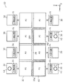
- FIG. 5 is a diagram showing another example of separation by airflow when the droplet infection suppression system 10 according to the present embodiment detects a cough or a sneeze.
- the pitch p of the lattice-shaped airflow generating units 26 may be, for example, an interval at which a person sits (for example, an interval at which the chair 30 is arranged).
- the pitch p is, for example, about 50 cm to 100 cm.
- the pitch p is the distance between the portions of the airflow generating section 26 that define the first region A1 and that are in a parallel relationship.
- the pitch p is, for example, the distance between the centers (for example, the center of the width d) of the portions having the parallel relationship.
- the control unit 25 may generate an airflow surrounding each of the persons h1 to h3. Specifically, the control unit 25 may cause the airflow generation unit 26 to generate an airflow that separates the second region A2 including the first region A1 where a person has been detected from another region. The control unit 25 may generate, for example, an airflow 26c that partitions the first area A1 where the people h1 and h2 are located, and an airflow 26d that partitions the first area A1 where the person h2 is located.
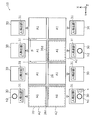
- FIG. 6 is a diagram illustrating another example of separation by airflow when the droplet infection suppression system 10 according to the present embodiment detects a cough or a sneeze. Specifically, the position where the person h3 is seated is different from FIG. 4 and FIG.
- the control unit 25 may generate an airflow surrounding each of the persons h1 to h3. Specifically, an example in which the control unit 25 generates an airflow that separates into a second region A2 including two first regions A1 adjacent in the X-axis direction (the direction in which a person faces). The control unit 25 generates, for example, an airflow that separates a second area A2 including two first areas A1 including the first area A1 where the person h1 is located from other areas. In addition, the control unit 25 generates an airflow that separates the second region A2 including the two first regions A1 including the first region A1 where the person h2 is located from other regions.
- control unit 25 generates an airflow that separates a second area A2 including four first areas A1 including the first area A1 including the person h3 from other areas. As shown in FIG. 6, when a plurality of second regions A2 are formed, the shapes of the plurality of second regions in plan view and the number of first regions included in the second regions may be different.
- the control unit 25 generates, for example, an airflow 26e for separating the person h1 from the person h2 and an airflow 26f for separating the person h2 from the person h3.
- the control unit 25 includes a second area A2 including the first area A1 including the person h1, a second area A2 including the first area A1 including the person h2, and a second area A1 including the first area A1 including the person h3. If the two regions A2 can be separated from each other, the airflow may be generated by an airflow pattern other than the airflow patterns shown in FIGS. Step S40 is an example of a step of causing the airflow generation unit 26 to generate an airflow that separates the second area A2 from other areas.
- the control unit 25 determines whether or not a predetermined time has elapsed since the start of the generation of the airflow (for example, the airflow 26b) in the airflow generation unit 26 (S50).
- the control unit 25 determines that the predetermined time has elapsed (Yes in S50)
- the control unit 25 turns off the airflow 26b by the airflow generation unit 26 (S60). That is, the control unit 25 stops the generation of the airflow 26b by the airflow generation unit 26.
- the predetermined time may be a time until the risk of droplet infection due to coughing or sneezing becomes equal to or lower than a predetermined value. Further, the predetermined time may be set according to the size of the desk 20 or the like. The predetermined period may be set longer as the desk 20 is larger, for example, 1 to 5 minutes.
- the control unit 25 determines whether the second cough or sneeze is detected (S70).
- a second cough or sneeze is a cough or sneeze that occurs after the first cough or sneeze.
- the control unit 25 stops measuring the elapsed time t due to the first cough or sneeze, The measurement of the elapsed time t due to the second cough or sneeze is started.
- the control unit 25 performs control to stop the airflow 26b after a lapse of a predetermined time after detecting a cough or a sneeze most recently.
- first cough or sneeze and the second cough or sneeze may be performed by the same person or different people.
- FIG. 4 illustrates the case where three persons h1 to h3 exist
- the control unit 25 determines that only one person is sitting (for example, the person h1) and that the person coughs or sneezes. If is detected, the airflow generation unit 26 may be controlled to generate an airflow surrounding the person. Specifically, an airflow that separates the second region A2 including the first region A1 where the person is located from other regions may be generated. Thus, for example, a person sitting on the chair 30 immediately after the person h1 coughs or sneezes can be prevented from being infected by droplets.
- control unit 25 may not generate the airflow in the airflow generation unit 26. Accordingly, when the risk of droplet infection to another person is low, the airflow generation unit 26 does not operate, so that the power consumption of the droplet infection suppression system 10 can be reduced.
- the airflow generation unit 26 capable of generating the airflow for separating the space into the plurality of first regions A1 and the person is detected for each of the plurality of first regions A1 (in the present embodiment, A person detecting unit 31 for detecting that a person is sitting on each of the chairs 30 provided at positions corresponding to the plurality of first areas A1, a detecting unit 24 for detecting coughing or sneezing, and a detecting unit 24 for coughing.
- a sneeze when a sneeze is detected, an airflow that separates a second area A2 including one or more first areas A1 including the first area A1 including a person detected by the person detection unit 31 from another area is generated.
- a control unit 25 for generating the data.
- the control unit 25 generates an airflow when detecting a cough or a sneeze, so that even if the infected person is not known in advance, there is another person who is coughed or sneezed by the infected person due to the airflow. It is possible to suppress reaching the region (other region). That is, infection to other people by coughing or sneezing can be suppressed. Further, the control unit 25 may generate a local airflow that separates the second region A2 from another region from the airflow generation unit 26 that can generate the airflow that separates the plurality of first regions A1.
- the droplet infection suppression system 10 can suppress the droplet infection by generating a local airflow. Therefore, the droplet infection suppression system 10 according to the present embodiment can appropriately suppress the droplet infection due to the cough or sneezing of the infected person.
- the control unit 25 may control the wind speed of the airflow generated from the airflow generation unit 26 according to the magnitude of the detected spectrum.
- the control unit 25 may increase the wind speed as the size of the detected spectrum increases. In this way, droplet infection can be prevented even for droplets that fly faster than expected.
- the droplet infection suppression system 10 includes a plurality of detection units 24 that detect a cough or a sneeze.
- the desk 20 is used by a large number of people. For example, when a plurality of microphones having directivity are installed on the desk 20, coughing or sneezing occurs at any place of the desk 20. Can be detected with high accuracy.
- the microphone may be embedded in the desk 20, for example.
- the following describes an airflow pattern in a case where the position of a coughing or sneezing person can be specified, that is, the first area A1 where a coughing or sneezing person exists can be detected.
- the operation of the droplet infection suppression system 10 is basically the same as that of the first embodiment, and the differences will be described with reference to FIG.
- the droplet infection suppression system 10 When detecting the first cough or sneeze in step S20, the droplet infection suppression system 10 according to the present embodiment further specifies the position of the person who coughed or sneezed. Specifically, the detection unit 24 specifies the first area A1 that follows the cough or sneeze. Then, in step S30, the control unit 25 calculates an airflow pattern according to the first area A1 in which a coughing or sneezing person exists. Specifically, the control unit 25 generates an airflow pattern that separates a person who has coughed or sneezed (infected person) from another person (subject).
- FIG. 7 is a diagram illustrating an example of separation by airflow when the droplet infection suppression system 10 according to the present embodiment detects a cough or a sneeze.
- the control unit 25 since the control unit 25 can detect the person h1 who has coughed or sneezed, the control unit 25 generates an airflow 26g having an airflow pattern that separates the person h1 from the other people h2 and h3. generate.
- the control unit 25 causes the airflow generation unit 26 to generate an airflow that separates the second region A2 including the first region A1 including the coughing or sneezing person h1 detected by the detection unit 24 from other regions.
- the control unit 25 generates, for example, an airflow 26g having an airflow pattern that surrounds the front and sides of the person h1. This can reduce the portion of the airflow generating section 26 that is generating the airflow, so that droplet infection can be effectively suppressed.
- FIG. 8 is a diagram illustrating another example of separation by airflow when the droplet infection suppression system 10 according to the present embodiment detects a cough or a sneeze.
- the detection unit 24 detects that the person h2 coughs or sneezes (FIG. 3). (Equivalent to Yes in step S70).
- the control unit 25 further generates an airflow 26h surrounding the person h2.
- the control unit 25 causes the airflow generation unit 26 to generate an airflow 26h that separates the second region A2 including the first region A1 including the coughing or sneezing person h2 detected by the detection unit 24 from other regions.
- the controller 25 does not have to reset the elapsed time during which the airflow 26g is generated when the generation of the airflow 26h is started. With this, when the risk of infection due to cough or sneezing of the person h1 is reduced in a state where the airflow 26h is generated, the airflow 26g can be stopped, so that the droplet infection can be appropriately performed while reducing power consumption. Can be suppressed.
- the detection unit 24 determines whether a person is detected in the two or more first areas A1. In which first area A1 the person in cough or sneeze is detected. Then, the control unit 25 generates an airflow (for example, an airflow 26g) that separates the second area A2 including the first area A1 in which the cough or sneeze detected by the detection unit 24 is present from the other area. To be generated.
- an airflow for example, an airflow 26g
- the airflow 26g that separates the second area including the first area A1 where the coughing or sneezing person is present from the other area only needs to be generated.
- the part where the airflow generation part 26 operates) can be reduced.
- a person who has coughed or sneezed (infected person) can be separated from another person (subject). That is, an airflow can be locally generated between a coughing or sneezing person (for example, the person h1) and a person (for example, the people h2 and h3) present in front of the person or the like. Exposure of the existing person to the droplets s can be suppressed. Therefore, it is possible to more appropriately suppress the infection by the cough or sneezing of the infected person. Specifically, it is possible to suppress the droplet infection while further reducing the power consumption in the droplet infection suppression system 10.
- the detection unit and the airflow generation unit are provided on the desk, and the human detection unit is provided on the chair.
- the present invention is not limited to this.
- a detection unit, an airflow generation unit, and a human detection unit may be provided in the space.
- the detection unit, the airflow generation unit, and the person detection unit may be provided, for example, on a floor, a wall, a ceiling, or the like that forms a space. For example, it may be embedded in a floor, a wall, a ceiling, or the like.
- the airflow generation unit may generate an airflow downward (for example, on the floor).
- the airflow generation unit may generate an airflow that crosses a person.
- the airflow is stopped after a predetermined time has elapsed, but the present invention is not limited to this. If the coughing or sneezing person can be specified, the airflow may be continuously generated while the human detection unit detects the coughing or sneezing person.
- the communication method between the devices is not particularly limited. Wireless communication may be performed between the devices, or wired communication may be performed.
- the droplet infection suppression system may be a system that performs control to generate an airflow in an airflow generation unit that can generate an airflow that separates a space into a plurality of first regions. Further, the droplet infection suppression system may be configured not to include the first detection unit and the second detection unit, but to include an acquisition unit that obtains a detection result from the first detection unit and the second detection unit. . That is, the droplet infection suppression system includes at least one of an acquisition unit (for example, a communication unit) that acquires detection results from the first detection unit and the second detection unit, and a first region including a person detected by the first detection unit.
- an acquisition unit for example, a communication unit
- detecting a person includes that the obtaining unit obtains a detection result from the first detecting unit. That is, the droplet infection suppression system may detect a person by acquiring the detection result of the first detection unit.
- Detecting a cough or a sneeze includes that the obtaining unit obtains the detection result from the second detecting unit. That is, the droplet infection suppression system may detect a cough or a sneeze by acquiring the detection result of the second detection unit.
- the order of the plurality of processes described in the above embodiment is an example.
- the order of the plurality of processes may be changed, and the plurality of processes may be executed in parallel.
- control unit may be realized by executing a software program suitable for each component.
- Each component may be realized by a program execution unit such as a CPU (Central Processing Unit) or a processor reading and executing a software program recorded on a recording medium such as a hard disk or a semiconductor memory.
- program execution unit such as a CPU (Central Processing Unit) or a processor reading and executing a software program recorded on a recording medium such as a hard disk or a semiconductor memory.
- a component such as a control unit may be a circuit (or an integrated circuit). These circuits may constitute one circuit as a whole, or may be separate circuits. Each of these circuits may be a general-purpose circuit or a dedicated circuit.
- the present disclosure may be realized as a program for causing a computer to execute a process performed by the droplet infection suppression system according to the above-described embodiment.
- a program includes an application program installed in a mobile terminal such as a smartphone or a tablet terminal.
- the present disclosure may be realized as a non-transitory computer-readable recording medium on which such a program is recorded.
- the program can be distributed via a transmission medium such as the Internet.
- the program and the digital signal including the program may be transmitted via an electric communication line, a wireless or wired communication line, a network represented by the Internet, data broadcasting, or the like.
- the program and a digital signal composed of the program may be implemented by another independent computer system by being recorded on a recording medium and transferred, or transferred via a network or the like. .
- the numbers such as ordinal numbers and quantities used above are all examples for specifically explaining the technology of the present disclosure, and the present disclosure is not limited to the illustrated numbers.
- the connection relationship between the components is illustrated for specifically describing the technology of the present disclosure, and the connection relationship that realizes the function of the present disclosure is not limited thereto.
- the present disclosure is applicable to, for example, a desk or the like that is arranged in a space where people performing communication and the like gather.
- Drop infection control system 20 Drop infection control desk (desk) 21 body part 22 top plate 23 support leg 24 detecting part (second detecting part) 25 control unit 26 airflow generation unit 26a to 26h airflow 27 communication unit 30 chair 31 person detection unit (first detection unit) 32 Communication unit A1 First area A2 Second area d Width h, h1 to h3 person p Pitch s Splash R space
Abstract
飛沫感染抑制システム(10)は、空間を複数の第1領域(A1)に分離するための気流を発生可能な気流発生部(26)と、複数の第1領域(A1)のそれぞれについて人を検出する第1検出部(31)と、空間における咳またはくしゃみを検出する第2検出部(24)と、第2検出部(24)が咳またはくしゃみを検出した場合に、第1検出部(31)によって検出された人がいる第1領域(A1)を含む1以上の第1領域(A1)からなる第2領域(A2)を他の領域から分離する気流を気流発生部(26)に発生させる制御部(25)とを備える。
Description
本開示は、感染症の感染を抑制する飛沫感染抑制システム、及び、飛沫感染抑制方法に関する。
感染症には、接触感染、飛沫感染、または、空気感染などの種々の感染ルートがある。例えば、インフルエンザの場合には一般的に、飛沫感染、または、空気感染が主要な感染ルートであると考えられている。したがって、ある感受者の集団の中に、感染者が存在すると、感染者の咳またはくしゃみに曝露された感受性者は感染し、または、感染者の呼気に含まれるインフルエンザウイルス等を吸い込んだ感受性者は感染し、場合によっては集団感染が起きる場合もある。
非特許文献1には、室内が換気されている場合に感染者が咳又はくしゃみをした場合にどのように飛沫が飛散していくかの数値シミュレーションによる結果が開示されている。この結果によれば、初速度10m/sで人が咳又はくしゃみをした場合には、5秒程度で1m先の感受者に到達し、感受者は感染者の咳またはくしゃみに曝露される。したがって、飛沫感染を防ぐためには10秒以内のごく短時間に感染者の飛沫から感受者を守る必要がある。
そして、そのような飛沫感染から感受者を守る技術の例として、例えば、特許文献1には、医師が患者を診断する際に、飛沫感染を防止する技術が開示されている。特許文献1によれば、医師をクリーンブースで囲い、クリーンブースから気流を発生させる。そして、風上側に医師を、風下側に患者を配置することで、医師が患者の咳に曝露されることを防ぐことができる。
また、特許文献2には、汚染空気の清浄化もしくはタバコの受動喫煙を防止する事を目的とした、空気清浄器付きの机が開示されている。特許文献2によれば、机の中央付近に吹き出し口と、吸い込み口、及び、除塵フィルタを設けており、吹き出し口から約180°の立体角で広範囲に気流を吹き出すことによって、部屋全体の気流が大きく循環し、効率よく汚染空気を清浄化できるとともに、煙を速やかに部屋全体に拡散させることで、受動喫煙を防止する事ができる。
Kang Z., Zhang Y., Fan H., Feng G., Proc. Eng. (2015) 114-121
しかしながら、例えば、特許文献1の方法は、予め感染者がわかっていない場合には、適用することが難しい。
また、特許文献2では、飛沫感染を抑制する技術については開示されていない。
そこで、本開示は、以上のような事情を鑑みたものであり、感染者の咳又はくしゃみにより飛沫感染することを適切に抑制することができる技術を提供するものである。
本開示の一態様に係る飛沫感染抑制システムは、空間を複数の第1領域に分離するための気流を発生する気流発生部と、前記複数の第1領域のそれぞれについて人を検出する第1検出部と、前記空間における咳またはくしゃみを検出する第2検出部と、前記第2検出部が前記咳またはくしゃみを検出した場合に、前記第1検出部によって検出された人がいる第1領域を含む1以上の第1領域からなる第2領域を他の領域から分離する気流を前記気流発生部に発生させる制御部とを備える。
尚、この包括的又は具体的な態様は、装置、方法、集積回路、コンピュータプログラム又はコンピュータ読み取り可能な記録媒体で実現されてもよく、装置、システム、方法、集積回路、コンピュータプログラム及びコンピュータ読み取り可能な記録媒体の任意な組み合わせで実現されてもよい。コンピュータ読み取り可能な記録媒体は、例えばCD-ROM(Compact Disc-Read Only Memory)等の不揮発性の記録媒体を含む。
本開示によれば、感染者の咳又はくしゃみにより飛沫感染することを適切に抑制することができる。
本開示の一態様における更なる利点および効果は、明細書および図面から明らかにされる。かかる利点および/または効果は、いくつかの実施形態並びに明細書および図面に記載された特徴によってそれぞれ提供されるが、1つまたはそれ以上の同一の特徴を得るために必ずしも全てが提供される必要はない。
(本開示の基礎となった知見)
感受者が感染者の咳又はくしゃみなどに暴露されてインフルエンザに感染すると、通常、1~2日の潜伏期間を経て、高熱や激しい倦怠感に見舞われる。特に、子供や高齢者といった健康弱者の場合には、重症化しやすく、最悪の場合では死亡するケース報告例もある。したがって、多くの高齢者が居住している老人介護施設などの施設では、インフルエンザ対策を徹底することが急務である。介護施設側では、特に、施設職員の手指衛生の徹底、感染症対策マニュアルによる対策など様々な感染症対策が実施されているが、施設外からの感染症の持ち込みによる集団感染は定期的に起きている。インフルエンザは先にも述べた通り、主には飛沫感染と空気感染とが主要な感染ルートであるから、感染者の咳若しくはくしゃみに曝露されないようにすることが重要な対策手段である。
感受者が感染者の咳又はくしゃみなどに暴露されてインフルエンザに感染すると、通常、1~2日の潜伏期間を経て、高熱や激しい倦怠感に見舞われる。特に、子供や高齢者といった健康弱者の場合には、重症化しやすく、最悪の場合では死亡するケース報告例もある。したがって、多くの高齢者が居住している老人介護施設などの施設では、インフルエンザ対策を徹底することが急務である。介護施設側では、特に、施設職員の手指衛生の徹底、感染症対策マニュアルによる対策など様々な感染症対策が実施されているが、施設外からの感染症の持ち込みによる集団感染は定期的に起きている。インフルエンザは先にも述べた通り、主には飛沫感染と空気感染とが主要な感染ルートであるから、感染者の咳若しくはくしゃみに曝露されないようにすることが重要な対策手段である。
しかしながら、例えば、特許文献1では、予め感染者が特定されていない場合には適用が難しい。また、クリーンブースを必要とするなどシステムが大掛かりである。医師などの特定の人を飛沫感染から守る技術としては使えるが、例えば、介護施設のコミュニティルームなど多数の高齢者が同時に存在する場合に、これら高齢者をすべて守るには、コスト面や装置の大きさを考えると、現実的ではない。
特許文献2には、飛沫感染を抑制することについては開示されていない。また、汚染空気の効率の良い清浄化を目的としているため、部屋全体に気流を循環する必要があり、これに必要となる流量が大流量となる。必然的にシステム自体も大掛かりになる。
そこで、本願発明者は、適切に感受者を飛沫感染から防ぐことについて鋭意検討を行った。そして、咳またはくしゃみを検出し、かつ飛沫感染抑制システムが設けられる空間(例えば、室内の部屋など)に存在する人の位置に応じて気流を発生させることで、上記課題を解決することを見出した。
本開示の一態様に係る飛沫感染抑制システムは、空間を複数の第1領域に分離するための気流を発生する気流発生部と、前記複数の第1領域のそれぞれについて人を検出する第1検出部と、前記空間における咳またはくしゃみを検出する第2検出部と、前記第2検出部が前記咳またはくしゃみを検出した場合に、前記第1検出部によって検出された人がいる第1領域を含む1以上の第1領域からなる第2領域を他の領域から分離する気流を前記気流発生部に発生させる制御部とを備える。
これにより、制御部は、咳又はくしゃみを検出したときに気流を発生させることで、感染者が予めわかっていない場合であっても、当該気流により感染者の咳又はくしゃみによる飛沫が他の人に到達することを抑制することができる。つまり、咳又はくしゃみによる他の人への感染を抑制することができる。また、制御部は、人がいる第1領域を含む第2領域を分離する気流を気流発生部に発生させればよい。つまり、制御部は、複数の第1領域に分離する気流を発生可能な気流発生部から、第2領域と他の領域とを分離する局所的な気流を発生させればよい。上記のように、飛沫感染抑制システムは、感染者がどこにいるかわかっていない状態であっても、局所的な気流の発生で飛沫感染を抑制することができる。よって、本実施の形態に係る飛沫感染抑制システムは、感染者の咳又はくしゃみにより飛沫感染することを適切に抑制することができる。さらに、飛沫感染抑制システムは、気流発生部が局所的な気流を発生できればよいので、装置自体が大掛かりになることを抑制しつつ、かつ気流発生部全体から気流を発生させる場合に比べ消費電力を低減することができる。
また、前記制御部は、前記第1検出部が前記複数の第1領域のうち2以上の第1領域において人を検出した場合、前記2以上の第1領域を互いに分離する気流を前記気流発生部に発生させる。
これにより、咳又はくしゃみが検出された場合に、2以上の第1領域それぞれにいる人を気流により分離することができるので、咳又はくしゃみをした人を特定することなく、飛沫感染を抑制することができる。よって、感染者の咳又はくしゃみにより飛沫感染することをさらに適切に抑制することができる。
また、前記第2検出部は、前記第1検出部が前記複数の第1領域のうち2以上の第1領域において人を検出した場合、前記2以上の第1領域のうちの前記咳またはくしゃみをした人がいる第1領域を検出し、前記制御部は、前記第2検出部が検出した前記咳またはくしゃみをした人がいる前記第1領域からなる前記第2領域を前記他の領域から分離する気流を前記気流発生部に発生させる。
これにより、咳又はくしゃみが検出された場合に、咳又はくしゃみをした人がいる第1領域を当該第1領域以外の領域から分離する気流を発生させればよいので、発生させる気流の量を低減しつつ、飛沫感染を抑制することができる。よって、感染者の咳又はくしゃみにより飛沫感染することをさらに適切に抑制することができる。
また、机をさらに備え、前記気流発生部は、前記机に設けられており、前記机から上方に向けて気流を発生する。
これにより、机の周りに複数の人がいる状況で、感染者が咳又はくしゃみをした場合に、上方に向けて気流を発生させることで、飛沫が感受者に到達することを抑制することができる。よって、机の周りに複数の人がいる状況であっても、感染者の咳又はくしゃみにより飛沫感染することをさらに適切に抑制することができる。
また、前記気流発生部の形状は、前記机の平面視において、格子状である。
これにより、人がいる第1領域に応じた気流を適切に発生させることができる。
また、前記第2検出部は、前記机に設けられる。
これにより、机は検出部と通信するための無線通信部等の構成要素を有していなくてもよいので、当該机の小型化が可能となる。
また、前記第2検出部は、マイクロフォン又はカメラを有する。
これにより、一般的に使用されているマイクロフォン又はカメラにより、検出部を実現することができる。よって、飛沫感染抑制システムの汎用性を向上させることができる。
また、椅子をさらに備え、前記第1検出部は、前記椅子に設けられる。
これにより、人が椅子に着座したか否かにより、人がいる第1領域を容易に検出することができる。
また、前記第1検出部は、赤外線センサ又は圧力センサを有する。
これにより、一般的に使用されている赤外線センサ又は圧力センサにより、人検出部を実現することができる。よって、飛沫感染抑制システムの汎用性を向上させることができる。
また、本開示の一態様に係る飛沫感染抑制方法は、複数の第1領域のそれぞれについて人を検出するステップと、咳またはくしゃみを検出するステップと、前記咳またはくしゃみが検出された場合に、検出された人がいる第1領域を含む1以上の第1領域からなる第2領域を他の領域から分離する気流を気流発生部に発生させるステップとを含む。
これにより、上記飛沫感染抑制システムと同様の効果を奏する。
なお、これらの包括的又は具体的な態様は、システム、装置、方法、集積回路、コンピュータプログラム、又は、コンピュータ読み取り可能なCD-ROMなどの非一時的な記録媒体で実現されてもよく、システム、装置、方法、集積回路、コンピュータプログラム、及び、記録媒体の任意な組み合わせで実現されてもよい。
以下、本開示の実施の形態に関して、図1~図8を用いて詳細に説明する。
なお、以下で説明する実施の形態は、いずれも包括的又は具体的な例を示すものである。以下の実施の形態で示される数値、形状、材料、構成要素、構成要素の配置位置及び接続形態、ステップ、ステップの順序などは、一例であり、請求の範囲を限定する主旨ではない。また、以下の実施の形態における構成要素のうち、最上位概念を示す独立請求項に記載されていない構成要素については、任意の構成要素として説明される。
なお、各図は、必ずしも厳密に図示したものではない。各図において、実質的に同一の構成については同一の符号を付し、重複する説明は省略又は簡略化する。
また、本明細書において、「上方」及び「下方」という用語は、絶対的な空間認識における上方向(鉛直上方)及び下方向(鉛直下方)を指す。なお、「上方」及び「下方」は、「鉛直上方」及び「鉛直下方」と完全に一致することに加え、実質的に同じ方向であることをも含む表現である。例えば、「上方」と「鉛直上方」とは、数%程度の誤差を含んでいてもよい。
また、本明細書および図面において、X軸、Y軸及びZ軸は、三次元直交座標系の三軸を示している。各実施の形態では、X軸方向及びY軸方向は、気流発生部が設けられる設置面と平行な方向とし、Z軸方向は当該設置面に対して垂直な方向としている。また、本明細書において、「平面視」とは、設置面に対して垂直な方向に沿って飛沫感染抑制システムを見た場合を意味する。
また、本明細書において、平行などの要素間の関係性を示す用語、及び、矩形などの要素の形状を示す用語、並びに、数値、及び、数値範囲は、厳格な意味を表す表現ではなく、実質的に同等な範囲、例えば数%程度の差異をも含むことを意味する表現である。
また、本明細書において、「感染」とは生体内にウイルス、細菌等の微生物が侵入することを指し、この生体の持ち主を感染者とも記載する。また、微生物が侵入していない生体の持ち主、すなわち感染していない生体の持ち主を感受者とも記載する。
(実施の形態1)
以下、本実施の形態に係る飛沫感染抑制システム等について、図1~図6を参照しながら説明する。
以下、本実施の形態に係る飛沫感染抑制システム等について、図1~図6を参照しながら説明する。
[1.飛沫感染抑制システムの概要]
まず、本実施の形態に係る飛沫感染抑制システム10の構成について、図1及び図2を参照しながら説明する。
まず、本実施の形態に係る飛沫感染抑制システム10の構成について、図1及び図2を参照しながら説明する。
図1は、本実施の形態に係る飛沫感染抑制システム10の概略構成を示す図である。図2は、本実施の形態に係る飛沫感染抑制システム10の機能構成を示すブロック図である。
図1に示すように、飛沫感染抑制システム10は、飛沫感染抑制机20(以降において、机20とも記載する)と、椅子30とを備える。机20と椅子30とは、空間Rに設置される。空間Rは、例えば、介護施設のコミュニティルーム、会社の会議室、及び、飲食店など複数の人hが集まり、椅子30に座って、机20でコミュニケーションを行うような空間である。また、空間Rとは、例えば、人hが搭乗する移動体(車両及び飛行機など)内の空間(例えば、閉鎖空間)であってもよい。また、空間Rは、屋外の空間であってもよい。なお、飛沫感染抑制システム10が備える机20及び椅子30の数は特に限定されない。
また、以下において、飛沫感染抑制システム10は、机20と椅子30とを備える構成について説明するが、これに限定されない。飛沫感染抑制システム10は、机20及び椅子30の少なくとも一方を備えていなくてもよい。飛沫感染抑制システム10は、例えば、移動体に設けられる場合、机20及び椅子30のうち椅子30のみを備えていてもよい。
また、人hは空間R内に存在する人であり、コミュニティルームなどで会話を行うなどの目的で空間R内に入室している人であってもよい。本実施の形態では、人hが感染症に感染しているかは、基本的には判定しない。人hが感染症に感染した場合、感染力を有する期間と、症状を発症する期間とがあり、通常、2つの期間は異なる。症状が現れ、体温が上昇するなどしていれば、感染している事はわかるが、実際にはそれよりもかなり前の段階で感染者は感染力を有している。そして、現時点での技術では感染力を有し始めた瞬間、すなわち感染者となった瞬間を捉えることは極めて困難であるので区別しない。ただし、予め医師の診断又は何かの測定によって、人hが感染者であるということが分かっている場合には、その情報を加味し、飛沫感染抑制システム10の制御方法を変更してもよい。より具体的には、感染者が咳又はくしゃみをしたときだけ、飛沫感染抑制システム10を動作させてもよい。なお、以下では、人hが感染症に感染しているいか否かの判定は行わない場合について説明する。
机20は、例えば、人hがコミュニケーション等を行う際に使用する為の机であるが、当該机20の用途はこれに限定されず、作業を行うための作業台であってもよいし、人hがその周囲に集まるのであればその他の用途に用いられる机であってもよい。机20は、図1及び図2に示すように、本体部21と、検出部24と、制御部25と、気流発生部26と、通信部27とを有する。本実施の形態において、飛沫感染抑制システム10が備える検出部24の数は、例えば1個である。
本体部21は、机20の本体部分であり、天板22と支持脚23とを有する。例えば、本体部21には、検出部24及び気流発生部26などが埋め込まれていてもよい。
天板22は、人hが書類などを広げるための板状の部材である。天板22は、例えば平板状であってもよいし、曲板状であってもよい。天板22の平面視における形状は特に限定されず、矩形状であってもよいし、円形であってもよいし、多角形であってもよい。また、天板22の材質は、特に限定されず、木材、金属、樹脂などの中から適宜選択することができる。
支持脚23は、天板22から下方に延設され、天板22を支持するための脚部である。支持脚23の形状は特に限定されず、机20を設置面(例えば、床など)に安定して配置できる形状であればよい。支持脚23の本数も特に限定されず、複数本であってもよい。また、支持脚23の材質は、特に限定されず、木材、金属、樹脂などの中から適宜選択すればよい。
検出部24は、空間Rにいる人hの咳またはくしゃみを検出する。本実施の形態では、検出部24は、咳及びくしゃみの両方を継続的に検出する。検出部24は、例えば、空間R内の椅子30に座っている人hの咳及びくしゃみを検出する。検出部24は、検出した結果を制御部25に出力する。検出部24は、第2検出部の一例である。
検出部24は、例えば、収音装置(例えば、マイクロフォン)を含んで構成されてもよい。検出部24は、例えば、マイクロフォンによる音声検出により、人hが咳又はくしゃみをしたことを検出する。検出部24は、マイクロフォンで取得した音声をスペクトル解析することによって、咳又はくしゃみであるか否かを判定することができる。この時、音の大きさ(dB)の閾値を設けてもよい。具体的には、検出部24は、閾値以下のスペクトルは検出対象外と判定することで、着座している人hの咳又はくしゃみを選択的に検出することができる。
なお、検出部24は、撮像装置(例えば、カメラ)を含んで構成されてもよい。検出部24は、撮像装置が撮像した画像を画像処理し分析することで、咳またはくしゃみを検出してもよい。この場合には、例えば、機械学習などの分類アルゴリズムによって、画像処理により得られた動作パターンが咳又はくしゃみであるか否かを容易に分類することができる。また、検出部24は、収音装置と撮像装置との組み合わせで構成されていてもよい。
検出部24は、例えば、机20の一部として組み込まれてもよい。これにより、机20の外部に検出部24が設けられている場合の、机20と検出部24との通信のための通信部を省くことができる。さらに、検出部24を咳又はくしゃみの発生場所の近傍に配置させることができるので、机20でコミュニケーションを行っている人hの咳又はくしゃみの検出を高精度に行える。検出部24を机20の一部に埋め込む場合には、例えば、小型のマイクロフォンを机20に埋め込むなどすればよい。
なお、検出部24は、机20に設けられることに限定されない。検出部24は、机20が設置される空間Rにおいて、咳及びくしゃみを検出することできる位置に設置されていればよい。この場合、検出部24は、咳又はくしゃみを検出すると、咳又はくしゃみを検出したことを示す検出フラグを机20に出力する。机20は、通信部27を介して検出フラグを取得する。なお、検出部24は、検出した情報を保存しておくメモリを有していていもよい。
制御部25は、机20の各構成要素を制御する制御装置である。制御部25は、例えば、検出部24の咳及びくしゃみの検出結果と、椅子30から取得する人の検出結果とから、気流発生部26に所定の気流を発生させる制御を行う。本実施の形態では、制御部25は、気流発生部26から上方に局所的な気流を発生させる。具体的には、制御部25は、咳又はくしゃみが検出されると、人検出部31が検出した人hがいる領域を他の領域から分離するような気流を気流発生部26に発生させる。また、制御部25は、現在の年月日及び時刻を計時するリアルタイムクロック機能を有していてもよい。
制御部25が気流発生部26に発生させる気流の風速について、図1を参照しながら説明する。制御部25が気流発生部26に発生させる気流の風速は、例えば、机20の大きさ、及び、気流発生部26から人hの口周辺までのZ軸方向と水平な方向の距離により決定される。図1に示すように、向かって左側の人hが対面している人hに向けて咳又はくしゃみをした場合、咳又はくしゃみによる飛沫sが気流発生部26の上方を通過する前に飛沫sの高さに到達する気流26aを発生させる必要がある。そこで、制御部25は、飛沫sが気流発生部26を通過するまでの時間内で、当該飛沫sが通過する高さに到達する風速の気流26aを発生させる。制御部25が制御する気流26aの風速は、例えば、数m/sである。咳又はくしゃみによる飛沫sの速度は、例えば、10m/sを用いてもよい。また、飛沫sが通過する高さは、例えば、飛沫感染抑制システム10が設置された空間Rを使用する人の属性(子供又は大人など)における平均的な身長等から算出されてもよい。また、気流26aの風速は、検出部24が咳又はくしゃみを検出してから気流発生部26が気流26aを発生させるまでのタイムラグを考慮して設定されてもよい。すなわち、風速は、飛沫sが気流発生部26を通過するまでの時間、飛沫sの高さ、及び、タイムラグに基づいて設定されてもよい。これにより、より確実に飛沫sが対面している人hに到達することを抑制することができる。
気流発生部26は、飛沫感染抑制システム10が設置された空間を複数の領域(後述する図4に示す第1領域A1)に分離する気流を発生可能な装置である。本実施の形態では、気流発生部26は、当該気流発生部26が設置された物体(本実施の形態では、机20)上の空間を複数の領域に分離可能である。また、気流発生部26は、制御部25の制御により、複数の領域のうちの所定の領域(複数の領域のうちの1以上の領域を含む領域であり、後述する図4に示す第2領域A2)を他の領域から分離する気流を発生する。
なお、本願明細書において、「分離」とは、異なる2つの領域(例えば、異なる2つ第2領域A2)の間に気流を発生させて、互いの領域の空気の流れを遮ることを意味する。「分離」とは、例えば、異なる2つの領域の間に飛沫sの位置までの気流の流れによる壁を発生させることで互いの領域の空気の流れを遮ることを意味する。また、「人を分離する」とは、例えば、異なる2つの領域(例えば、異なる2つ第2領域A2)それぞれに人がいる場合、当該2つの領域の間に気流を発生させることで、人がいる領域同士の空気の流れを遮ることを意味する。
なお、本実施の形態では、机20の天板22の上部に埋め込まれて設置される。
気流発生部26は、DC(Direct Current)ファンなど気流を発生させるデバイスを使用することができる。DCファンなどの気流発生装置を机20にアレイ状に埋め込むことで、スポット状の気流ではなく、エアカーテンのように面状の気流を生成することができる。言い換えると、気流発生部26は、エアカーテンのような面状の気流を発生させる装置である。
なお、エアカーテンとは、一般的に用いられているエアカーテンという用語と同様の概念を示すものであり、特に特異な概念を示すものではなく空気の流れにより一種の壁のような状態を構成するものを示す。すなわち、本実施の形態におけるエアカーテンは、空気の流れを遮断する機能を奏するものである。気流発生部26は、この点において温度調節機能を主目的として温度の伝達を効率良く行なうべく空気を循環又は混合するために送風する機能を奏するエア・コンディショナーとは異なる。
また、気流発生部26は、対面する人h同士の中間の位置(図1では、対面する2人の人hのX軸方向における中間の位置)に設けられるとよい。これにより、対面する人hのどちらが咳又はくしゃみをしても、同程度に飛沫感染を抑制することができる。
通信部27は、椅子30から人hを検出したことを示す信号を取得する。通信部27は、通信回路から構成される。なお、机20が検出部24及び人検出部31を備えている場合、通信部27は設けられなくてもよい。
通信部27が無線通信回路である場合、椅子30から送信される信号を受信するが、送信されてくる信号の方向及び強度により、当該椅子30と机20との相対的な位置関係を取得することができる。つまり、人hがどの椅子30に着座しているかを、検出することができる。なお、机20は、当該机20と椅子30との相対的な位置関係を精度よく検出する観点から、通信部27を複数有していてもよい。
椅子30は、人hが着座する椅子であり、机20の周囲に配置される。図1及び図2に示すように、椅子30は、人検出部31と、通信部32とを有する。
人検出部31は、椅子30に人hが着座しているか否かを検出する。人検出部31は、例えば、椅子30に埋め込まれた赤外線センサ又は圧力センサによって実現される。これにより、人hを容易に検出することができ、システムの実装がより容易になる。人検出部31が椅子30に設けられる場合、複数の椅子30のそれぞれに人検出部31が設けられる。これにより、介護施設のコミュニティルーム及びオフィスの会議室など多数の人が同時にコミュニケーションを行うような場合に、どこに人が存在している(着座している)かを容易に判定することができる。
なお、人検出部31は、椅子30に設けられていなくてよい。人検出部31は、例えば、椅子30の外部に設置されていてもよい。人検出部31は、例えば机20に設置されていてもよい。また、人検出部31は、撮像装置であってもよいし、人hが身に着けるタグなどウエラブルセンサから信号を取得することで人を検出する取得部であってもよい。また、人検出部31は、第1検出部の一例である。
通信部32は、人検出部31が人hを検出すると、机20に人hを検出したことを示す信号を出力する。通信部32は、人検出部31が人hを検出している間、信号の出力を継続してもよいし、人hの検出の開始及び終了を示す信号を出力してもよい。
[2.飛沫感染抑制システムの動作]
次に、本実施の形態に係る飛沫感染抑制システム10の動作について、図3~図6を参照しながら説明する。
次に、本実施の形態に係る飛沫感染抑制システム10の動作について、図3~図6を参照しながら説明する。
図3は、本実施の形態に係る飛沫感染抑制システム10の動作の一例を示すフローチャートである。なお、図3において、飛沫感染抑制システム10の各構成要素は、電源が入っているものとする。
図3に示すように、机20は、まず椅子30から人の在/不在の情報を取得する(S10)。制御部25は、通信部27を介して複数の椅子30のそれぞれから、人の在/不在の情報を取得する。制御部25は、例えば、椅子30から当該椅子30が有する人検出部31が人を検出したことを示す情報を取得することで、人の在/不在の情報を取得する。言い換えると、人検出部31は、複数の椅子30のそれぞれについて、人を検出する。これにより、制御部25は、どの椅子30に人hが着座しているかを検出することができる。制御部25は、複数の人hがそれぞれ椅子30に着座している場合、複数の人hがそれぞれどの椅子30に着座しているかを人検出部31の検出結果から検出することができる。すなわち、制御部25は、咳又はくしゃみから防がれる人hがどの椅子30に着座しているかを検出することができる。
なお、ステップS10において人検出部31が複数の椅子30のそれぞれについて人を検出することは、複数の第1領域(図4に示す第1領域A1)のそれぞれについて人を検出することに相当する。また、ステップS10は、複数の第1領域A1のそれぞれについて人を検出するステップの一例である。
次に、検出部24は、第1の咳又はくしゃみを検出したか否かを判定する(S20)。制御部25は、検出部24(例えば、机20に埋め込まれたマイクロフォン)の検出結果を取得する。なお、本実施の形態では、机20の周囲のどこで咳又はくしゃみが発生したかは検出しない。すなわち、着座している複数の人hのうち、誰が咳又はくしゃみをしたかは検出しない。なお、ステップS20は、咳またはくしゃみを検出するステップの一例である。
制御部25は、検出部24が咳又はくしゃみを検出した場合(S20でYes)、人hの位置に応じて、気流制御パターンを計算する(S30)。制御部25は、着座している人hを飛沫感染の暴露から防ぐために、人hを分離する気流パターンを計算する。制御部25は、複数の人hの誰が咳又はくしゃみをしたかを検出しないので、当該複数の人hそれぞれを分離する気流26aを発生させるための気流パターンを計算する。具体的には、制御部25は、複数の人hそれぞれがいる領域を分離するための気流26aを発生させる気流パターンを計算する。そして、制御部25は、計算した気流パターンに基づいて、気流発生部26に気流26aをonさせる(S40)。すなわち、制御部25は、気流発生部26に気流26aの発生を開始させる。本実施の形態では、制御部25は、気流発生部26に上方に向けて気流26aを発生させる。なお、制御部25は、気流発生部26に気流26aを発生させるとともに、気流26aを発生させている経過時間の計測を開始する。
ここで、気流発生部26が発生する気流のパターンについて、図4を参照しながら説明する。図4は、本実施の形態に係る飛沫感染抑制システム10が咳又はくしゃみを検出したときの気流による分離の一例を示す図である。図4は、机20を平面視したときの図である。
なお、図4では、机20の天板22に格子状に気流発生部26が設けられている例を示している。気流発生部26は、例えば、机20の長手方向及び短手方向と平行な方向に延びて形成される。気流発生部26は、机20上の空間を8つの第1領域A1に分離する気流を発生可能なように設けられている。気流発生部26は、当該気流発生部26により分離される複数の第1領域A1の面積がそれぞれ等しいように設けられてもよい。また、飛沫感染抑制システム10が備える椅子30は、8脚であり、そのうち3脚に人が着座しているとする。また、気流発生部26の幅dは、例えば想定される飛沫sの大きさ等により決定される。気流発生部26の幅dは、例えば、1cm程度である。また、図4におけるドットハッチングは、気流発生部26のうち気流を発生させている部分を示す。
なお、気流発生部26は、机20の機能を阻害しない形状であれば、格子状であることに限定されない。また、机20が会議室などで使用される机である場合、気流発生部26は、例えば、机20の上にある書類などが気流で飛ぶことを防ぐため、天板22の全面には設けられない。
制御部25は、ステップS10により、3人の人h1~h3が図4に示す位置に着座していることを示す情報を取得する。そして、人h1が咳又はくしゃみをしたとする。すなわち、図4の場合、人h1は感染者であり、人h2及びh3は感受者である。制御部25は、検出部24が人h1の咳又はくしゃみを検出すると、人h1~人h3を分離するための気流を発生させる気流パターンを計算し、当該気流パターンに応じた気流26bを気流発生部26に発生させる。制御部25は、格子状の気流発生部26のうち、気流パターンに応じた部分から気流を発生させる。すなわち、制御部25は、複数の第1領域A1のうち人検出部31が検出した人がいる第1領域A1を含む1以上の第1領域A1からなる第2領域A2を他の領域から分離する気流を気流発生部26に発生させる。言い換えると、制御部25は、第1検出部31によって人が検出された第1領域A1を、少なくとも1つの他の第1領域A1から分離する気流を気流発生部26に発生させる。
具体的には、制御部25は、Y軸方向(人が並ぶ方向)に隣り合う2つの第1領域A1を含む第2領域A2に分離する気流を発生している例を示している。制御部25は、例えば、人h1がいる第1領域A1を含む2つの第1領域A1からなる第2領域A2を他の領域から分離する気流を発生させている。また、制御部25は、人h2がいる第1領域A1を含む2つの第1領域A1からなる第2領域A2を他の領域から分離する気流を発生させている。また、制御部25は、人h3がいる第1領域A1を含む2つの第1領域A1からなる第2領域A2を他の領域から分離する気流を発生させている。
これにより、咳又はくしゃみをした人が特定できていない場合であっても、咳又はくしゃみをした人(例えば、人h1)以外で着座している人(例えば、人h2及びh3)が飛沫sに暴露されることを抑制することができる。また、格子状の気流発生部26のうち、十字状の部分を動作させることで、飛沫感染を抑制することができる。言い換えると、気流発生部26の全域を動作させることなく、飛沫感染を抑制することができる。
なお、気流パターンは、図4に示すパターンに限定されない。気流パターンの他の例について、図5及び図6を参照しながら説明する。図5は、本実施の形態に係る飛沫感染抑制システム10が咳又はくしゃみを検出したときの気流による分離の他の一例を示す図である。なお、格子状の気流発生部26のピッチpは、例えば、人が座る間隔(例えば、椅子30が配置される間隔)であるとよい。ピッチpは、例えば、50cm~100cm程度である。なお、ピッチpとは、気流発生部26の第1領域A1を区画するための部分のうち、平行な関係にある部分の距離である。ピッチpは、例えば、当該平行な関係にある部分の中央(例えば、幅dの中央)同士の距離である。
図5に示すように、制御部25は、検出部24が咳又はくしゃみを検出すると、人h1~h3のそれぞれを囲むような気流を発生させてもよい。具体的には、制御部25は、人が検出された第1領域A1からなる第2領域A2を他の領域から分離する気流を気流発生部26に発生させてもよい。制御部25は、例えば、人h1及びh2がいる第1領域A1それぞれを区画する気流26cと、人h2がいる第1領域A1を区画する気流26dとを発生させてもよい。
図6は、本実施の形態に係る飛沫感染抑制システム10が咳又はくしゃみを検出したときの気流による分離の他の一例を示す図である。具体的には、図4及び図5とは、人h3が着座している位置が異なる。
図6に示すように、制御部25は、検出部24が咳又はくしゃみを検出すると、人h1~h3のそれぞれを囲むような気流を発生させてもよい。具体的には、制御部25は、X軸方向(人が対面する方向)に隣り合う2つの第1領域A1を含む第2領域A2に分離する気流を発生している例を示している。制御部25は、例えば、人h1がいる第1領域A1を含む2つの第1領域A1からなる第2領域A2を他の領域から分離する気流を発生させている。また、制御部25は、人h2がいる第1領域A1を含む2つの第1領域A1からなる第2領域A2を他の領域から分離する気流を発生させている。また、制御部25は、人h3がいる第1領域A1を含む4つの第1領域A1からなる第2領域A2を他の領域から分離する気流を発生させている。図6に示すように、複数の第2領域A2が形成される場合、複数の第2領域の平面視形状及び第2領域に含まれる第1領域の数は異なっていてもよい。制御部25は、例えば、人h1と人h2とを分離するための気流26eと、人h2と人h3とを分離するための気流26fとを発生させる。
なお、制御部25は、人h1がいる第1領域A1を含む第2領域A2と、人h2がいる第1領域A1を含む第2領域A2と、人h3がいる第1領域A1を含む第2領域A2とを分離することができれば、図4~図6に示す気流パターン以外の気流パターンにより気流を発生させてもよい。なお、ステップS40は、第2領域A2を他の領域から分離する気流を気流発生部26に発生させるステップの一例である。
図3を再び参照して、次に、制御部25は、気流発生部26に気流(例えば、気流26b)の発生を開始してから所定時間経過したか否かの判定を行う(S50)。制御部25は、所定時間経過していると判定する(S50でYes)と、気流発生部26による気流26bをoffする(S60)。すなわち、制御部25は、気流発生部26による気流26bの発生を停止させる。なお、所定時間は、咳又はくしゃみによる飛沫感染のリスクが所定の以下となるまでの時間であってもよい。また、所定時間は、机20の大きさなどにより設定されてもよい。所定の期間は、机20が大きいほど長く設定されてもよく、例えば、1~5分である。
また、制御部25は、所定時間経過していないと判定する(S50でNo)と、第2の咳又はくしゃみを検出したか否かの判定を行う(S70)。第2の咳又はくしゃみとは、第1の咳又はくしゃみの後に発生した咳又はくしゃみである。制御部25は、第2の咳又はくしゃみを検出する、つまり第1の咳又はくしゃみによる気流26bが発生しているときに第2の咳又はくしゃみを検出する(S70Yes)と、経過時間tをリセット(t=0)(S80)し、最初から経過時間tの計測を行う。言い換えると、制御部25は、第1の咳又はくしゃみによる気流26bを発生させているときに第2の咳又はくしゃみを検出すると、第1の咳又はくしゃみによる経過時間tの計測を停止し、第2の咳又はくしゃみによる経過時間tの計測を開始する。制御部25は、最も直近に咳又はくしゃみを検出してから所定時間経過後に気流26bを停止する制御を行う。これにより、気流26bの発生中に生じた第2の咳又はくしゃみによる飛沫感染が発生することを抑制することができる。なお、第2の咳又はくしゃみが検出されない(S70でNo)と、経過時間tのカウントを1増やし(t=t+1)(S90)、ステップS50に戻り、再度経過時間の判定が行われる。
なお、第1の咳又はくしゃみと第2の咳又はくしゃみとは同一の人により行われてもよいし、異なる人によって行われてもよい。
なお、図4では、3人の人h1~h3が存在する場合について説明したが、制御部25は、着座している人が1人(例えば、人h1)であり、当該人の咳又はくしゃみが検出された場合、気流発生部26を制御し、当該人を囲む気流を発生させてもよい。具体的には、当該人がいる第1領域A1を含む第2領域A2を他の領域から分離する気流を発生させてもよい。これにより、例えば、人h1が咳又はくしゃみをした直後に椅子30に着座した人が飛沫感染することを抑制することができる。また、制御部25は、着座している人が1人であり、当該人の咳又はくしゃみが検出された場合、気流発生部26に気流を発生させなくてもよい。これにより、他の人に飛沫感染するリスクが低いときに、気流発生部26が動作しないので、飛沫感染抑制システム10の消費電力を低減することができる。
上記のように、空間を複数の第1領域A1に分離するための気流を発生可能な気流発生部26と、当該複数の第1領域A1のそれぞれについて人を検出する(本実施の形態では、複数の第1領域A1に対応する位置に設けられる椅子30それぞれに人が着座していることを検出する)人検出部31と、咳またはくしゃみを検出する検出部24と、検出部24が咳またはくしゃみを検出した場合に、人検出部31によって検出された人がいる第1領域A1を含む1以上の第1領域A1からなる第2領域A2を他の領域から分離する気流を気流発生部26に発生させる制御部25とを備える。
制御部25は、咳又はくしゃみを検出したときに気流を発生させることで、感染者が予めわかっていない場合であっても、当該気流により感染者の咳又はくしゃみによる飛沫が他の人がいる領域(他の領域)に到達することを抑制することができる。つまり、咳又はくしゃみによる他の人への感染を抑制することができる。また、制御部25は、複数の第1領域A1に分離する気流を発生可能な気流発生部26から、第2領域A2と他の領域とを分離する局所的な気流を発生させればよい。上記のように、飛沫感染抑制システム10は、感染者がどこにいるかわかっていない状態であっても、局所的な気流の発生で飛沫感染を抑制することができる。よって、本実施の形態に係る飛沫感染抑制システム10は、感染者の咳又はくしゃみにより飛沫感染することを適切に抑制することができる。
咳又はくしゃみによる飛沫は、例えば5~8秒以内に1m先まで到達するため、通常のエア・コンディショナー及び空気清浄機の風向制御では風の到達が間に合わず飛沫感染を抑制できない可能性が高い。一方、本実施の形態に係る飛沫感染抑制システム10によれば、咳又はくしゃみが発生する近傍である机20から直接気流(例えば気流26b)を発生させるので、気流26bの形成を間に合わせることができる。
これにより、飛沫感染という短い期間のイベントを防ぐことができる。また、人hによっては咳又はくしゃみの飛散速度が異なる可能性もある。そこで、制御部25は、例えば、マイクロフォンを咳又はくしゃみの検出に用いた場合に、検出されるスペクトルの大きさによって、気流発生部26から発生する気流の風速を制御してもよい。制御部25は、検出されるスペクトルの大きさが大きいほど、風速を速くしてもよい。こうすることで、通常予測されるより速く飛散する飛沫に対しても飛沫感染を防ぐことができる。
(実施の形態2)
以下、本実施の形態に係る飛沫感染抑制システム10等について、図7及び図8を参照しながら説明する。なお、本実施の形態では、主に実施の形態1と異なる点について説明し、実施の形態1と同様の構成については説明を省略又は簡略化する。本実施の形態に係る飛沫感染抑制システム10は、咳又はくしゃみを検出する検出部24を複数備えている。本実施の形態では机20が多人数で使用されることを想定しており、例えば、指向性を有するマイクロフォンを机20に複数設置することで、机20のどの場所で咳又はくしゃみが発生したかを高精度に検出することができる。マイクロフォンは、例えば、机20に埋め込まれていてもよい。
以下、本実施の形態に係る飛沫感染抑制システム10等について、図7及び図8を参照しながら説明する。なお、本実施の形態では、主に実施の形態1と異なる点について説明し、実施の形態1と同様の構成については説明を省略又は簡略化する。本実施の形態に係る飛沫感染抑制システム10は、咳又はくしゃみを検出する検出部24を複数備えている。本実施の形態では机20が多人数で使用されることを想定しており、例えば、指向性を有するマイクロフォンを机20に複数設置することで、机20のどの場所で咳又はくしゃみが発生したかを高精度に検出することができる。マイクロフォンは、例えば、机20に埋め込まれていてもよい。
以下に、咳又はくしゃみをした人の位置を特定することができる、つまり咳又はくしゃみをした人がいる第1領域A1を検出することができる場合における気流パターンについて説明する。なお、飛沫感染抑制システム10の動作は、基本的には実施の形態1と同様であり、相違点を図3を参照しながら説明する。
本実施の形態に係る飛沫感染抑制システム10は、ステップS20において、第1の咳又はくしゃみを検出した場合、さらに当該咳又はくしゃみをした人の位置を特定する。具体的には、検出部24は、咳又はくしゃみをしたがいる第1領域A1を特定する。そして、制御部25は、ステップS30において、咳又はくしゃみをした人がいる第1領域A1に応じて、気流パターンを計算する。具体的には、制御部25は、咳又はくしゃみをした人(感染者)と、それ以外の人(感受者)とを分離するような気流パターンを生成する。図7は、本実施の形態に係る飛沫感染抑制システム10が咳又はくしゃみを検出したときの気流による分離の一例を示す図である。
図7に示すように、制御部25は、咳又はくしゃみを行った人h1を検出できているので、当該人h1とそれ以外の人h2及びh3とを分離するような気流パターンの気流26gを発生させる。制御部25は、検出部24が検出した咳またはくしゃみをした人h1がいる第1領域A1からなる第2領域A2を他の領域から分離する気流を気流発生部26に発生させる。制御部25は、例えば、当該人h1の正面及び側方を囲むような気流パターンの気流26gを発生させる。これにより、気流発生部26のうち気流を発生させている部分を少なくすることができるので、効果的に飛沫感染を抑制することができる。
また、図7に示す気流26gが発生している状態で、人h2が咳又はくしゃみをした場合について、図8を参照しながら説明する。図8は、本実施の形態に係る飛沫感染抑制システム10が咳又はくしゃみを検出したときの気流による分離の他の一例を示す図である。
図8に示すように、図7に示す気流26gが発生している状態で、人h2が咳又はくしゃみをした場合、検出部24は人h2が咳又はくしゃみをしたことを検出する(図3に示すステップS70でYesに相当)。制御部25は、さらに人h2を囲む気流26hを発生させる。制御部25は、検出部24が検出した咳又はくしゃみをした人h2がいる第1領域A1からなる第2領域A2を他の領域から分離する気流26hを気流発生部26に発生させる。これにより、複数人が咳又はくしゃみをした場合であっても、効果的に飛沫感染を抑制することができる。
なお、制御部25は、気流26hの発生を開始したときに、気流26gを発生させている経過時間をリセットしなくてもよい。これにより、気流26hが発生している状態で、人h1の咳又はくしゃみによる感染のリスクが低減したときに、気流26gを停止させることができるので、消費電力を低減しつつ、適切に飛沫感染を抑制することができる。
上記のように、人検出部31が、複数の第1領域A1のうち2以上の第1領域A1において人を検出しとときに、検出部24は、2以上の第1領域A1のうちのどの第1領域A1にいる人が咳またはくしゃみをしたかを検出する。そして、制御部25は、検出部24が検出した咳またはくしゃみをした人がいる第1領域A1からなる第2領域A2を他の領域から分離する気流(例えば、気流26g)を気流発生部26に発生させる。
これにより、咳又はくしゃみをした人がいる第1領域A1からなる第2領域を他の領域から分離する気流26gを発生させればよいので、気流発生部26において気流を発生させる部分(例えば、気流発生部26が動作する部分)を少なくすることができる。また、咳又はくしゃみをした人(感染者)を他の人(感受者)から分離することができる。つまり、咳又はくしゃみをした人(例えば、人h1)とその人の正面等に存在する人(例えば、人h2及びh3)との間に局所的に気流を発生させることができ、正面等に存在する人が飛沫sに曝露されることを抑制することができる。よって、感染者の咳又はくしゃみにより飛沫感染することをさらに適切に抑制することができる。具体的には、飛沫感染抑制システム10における消費電力をさらに低減しつつ、飛沫感染を抑制することができる。
(その他の実施の形態)
以上、本開示の1つまたは複数の態様に係る飛沫感染抑制システム等について、実施の形態に基づいて説明したが、本開示は、この実施の形態に限定されるものではない。本開示の趣旨を逸脱しない限り、当業者が思いつく各種変形を本実施の形態に施したものも、本開示の1つまたは複数の態様の範囲内に含まれてもよい。
以上、本開示の1つまたは複数の態様に係る飛沫感染抑制システム等について、実施の形態に基づいて説明したが、本開示は、この実施の形態に限定されるものではない。本開示の趣旨を逸脱しない限り、当業者が思いつく各種変形を本実施の形態に施したものも、本開示の1つまたは複数の態様の範囲内に含まれてもよい。
例えば、上記実施の形態では、検出部及び気流発生部が机に設けられ、人検出部が椅子に設けられる例について説明したが、これに限定されない。飛沫感染抑制システムが屋内の空間に設けられる場合、当該空間内に検出部、気流発生部、及び、人検出部が設けられていればよい。検出部、気流発生部、及び、人検出部は、例えば、空間を構成する床、壁、天井などに設けられていてもよい。例えば、床、壁、天井などに埋め込まれていてもよい。
また、上記実施の形態では、気流発生部は上方に向けて気流を発生する例について説明したが、これに限定されない。気流発生部が天井などの人より高い位置に設けられる場合、当該気流発生部は下方(例えば床)に向けて気流を発生させてもよい。また、気流発生部が壁などに設けられる場合、当該気流発生部は人を横切るような気流を発生させてもよい。
また、上記実施の形態では、気流は所定時間経過すると停止される例について説明したが、これに限定されない。咳又はくしゃみをした人を特定することができる場合、人検知部が咳又はくしゃみをした人を検出している間、継続して気流を発生させてもよい。
また、上記実施の形態における装置間(例えば、机と椅子との間など)の通信方法については特に限定されない。装置間では、無線通信が行われてもよいし、有線通信が行われてもよい。
また、上記実施の形態では、飛沫感染抑制システムが気流発生部を備える例について説明したが、これに限定されない。飛沫感染抑制システムは、空間を複数の第1領域に分離する気流を発生可能な気流発生部に気流を発生させる制御を行うシステムであってもよい。また、飛沫感染抑制システムは、さらに、第1検出部および第2検出部を備えておらず、第1検出部及び第2検出部から検出結果を取得する取得部を備える構成であってもよい。すなわち、飛沫感染抑制システムは、第1検出部及び第2検出部から検出結果を取得する取得部(例えば、通信部)と、第1検出部が検出した人がいる第1領域を含む1以上の第1領域からなる第2領域を他の領域から分離する気流を発生させる制御信号を気流発生部に出力する制御部とを備える構成であってもよい。また、「人を検出する」には、取得部が第1検出部から検出結果を取得することが含まれる。すなわち、飛沫感染抑制システムは、第1検出部の検出結果を取得することで、人を検出してもよい。また、「咳またはくしゃみを検出する」には、取得部が第2検出部から検出結果を取得することが含まれる。すなわち、飛沫感染抑制システムは、第2検出部の検出結果を取得することで、咳またはくしゃみを検出してもよい。
また、上記実施の形態において説明された複数の処理の順序は一例である。複数の処理の順序は、変更されてもよいし、複数の処理は、並行して実行されてもよい。
また、上記実施の形態において、制御部などの構成要素の全部又は一部は、各構成要素に適したソフトウェアプログラムを実行することによって実現されてもよい。各構成要素は、CPU(Central Processing Unit)またはプロセッサなどのプログラム実行部が、ハードディスクまたは半導体メモリなどの記録媒体に記録されたソフトウェアプログラムを読み出して実行することによって実現されてもよい。
また、上記実施の形態において、制御部などの構成要素の全部又は一部は、ハードウェアによって実現されてもよい。例えば、制御部などの構成要素は、回路(または集積回路)でもよい。これらの回路は、全体として1つの回路を構成してもよいし、それぞれ別々の回路でもよい。また、これらの回路は、それぞれ、汎用的な回路でもよいし、専用の回路でもよい。
また、例えば、本開示は、上記実施の形態の飛沫感染抑制システムが行う処理をコンピュータに実行させるためのプログラムとして実現されてもよい。このようなプログラムには、スマートフォンまたはタブレット端末などの携帯端末にインストールされるアプリケーションプログラムが含まれる。また、本開示は、このようなプログラムが記録されたコンピュータ読み取り可能な非一時的な記録媒体として実現されてもよい。また、上記プログラムは、インターネット等の伝送媒体を介して流通させることができるのは言うまでもない。例えば、上記プログラム及び上記プログラムからなるデジタル信号は、電気通信回線、無線又は有線通信回線、インターネットを代表とするネットワーク、データ放送等を経由して伝送するものであってもよい。また、上記プログラム及び上記プログラムからなるデジタル信号は、記録媒体に記録して移送されることにより、又はネットワーク等を経由して移送されることにより、独立した他のコンピュータシステムにより実施されてもよい。
また、上記で用いた序数、数量等の数字は、全て本開示の技術を具体的に説明するために例示するものであり、本開示は例示された数字に制限されない。また、構成要素間の接続関係は、本開示の技術を具体的に説明するために例示するものであり、本開示の機能を実現する接続関係はこれに限定されない。
その他、実施の形態に対して当業者が思いつく各種変形を施して得られる形態や、本開示の趣旨を逸脱しない範囲で各実施の形態における構成要素および機能を任意に組み合わせることで実現される形態も本開示に含まれる。
本開示は、例えば、コミュニケーションなどを行う人が集まる空間に配置される机などに適用可能である。
10 飛沫感染抑制システム
20 飛沫感染抑制机(机)
21 本体部
22 天板
23 支持脚
24 検出部(第2検出部)
25 制御部
26 気流発生部
26a~26h 気流
27 通信部
30 椅子
31 人検出部(第1検出部)
32 通信部
A1 第1領域
A2 第2領域
d 幅
h、h1~h3 人
p ピッチ
s 飛沫
R 空間
20 飛沫感染抑制机(机)
21 本体部
22 天板
23 支持脚
24 検出部(第2検出部)
25 制御部
26 気流発生部
26a~26h 気流
27 通信部
30 椅子
31 人検出部(第1検出部)
32 通信部
A1 第1領域
A2 第2領域
d 幅
h、h1~h3 人
p ピッチ
s 飛沫
R 空間
Claims (11)
- 空間を複数の第1領域に分離するための気流を発生する気流発生部と、
前記複数の第1領域のそれぞれについて人を検出する第1検出部と、
前記空間における咳またはくしゃみを検出する第2検出部と、
前記第2検出部が前記咳またはくしゃみを検出した場合に、前記第1検出部によって検出された人がいる第1領域を含む1以上の第1領域からなる第2領域を他の領域から分離する気流を前記気流発生部に発生させる制御部とを備える
飛沫感染抑制システム。 - 前記制御部は、前記第1検出部が前記複数の第1領域のうち2以上の第1領域において人を検出した場合、前記2以上の第1領域を互いに分離する気流を前記気流発生部に発生させる
請求項1に記載の飛沫感染抑制システム。 - 前記第2検出部は、前記第1検出部が前記複数の第1領域のうち2以上の第1領域において人を検出した場合、前記2以上の第1領域のうちの前記咳またはくしゃみをした人がいる第1領域を検出し、
前記制御部は、前記第2検出部が検出した前記咳またはくしゃみをした人がいる前記第1領域からなる前記第2領域を前記他の領域から分離する気流を前記気流発生部に発生させる
請求項1に記載の飛沫感染抑制システム。 - 机をさらに備え、
前記気流発生部は、前記机に設けられており、前記机から上方に向けて気流を発生する
請求項1~3のいずれか1項に記載の飛沫感染抑制システム。 - 前記気流発生部の形状は、前記机の平面視において、格子状である
請求項4に記載の飛沫感染抑制システム。 - 前記第2検出部は、前記机に設けられる
請求項4又は5に記載の飛沫感染抑制システム。 - 前記第2検出部は、マイクロフォン又はカメラを有する
請求項1~6のいずれか1項に記載の飛沫感染抑制システム。 - 椅子をさらに備え、
前記第1検出部は、前記椅子に設けられる
請求項1~7のいずれか1項に記載の飛沫感染抑制システム。 - 前記第1検出部は、赤外線センサ又は圧力センサを有する
請求項1~8のいずれか1項に記載の飛沫感染抑制システム。 - 複数の第1領域のそれぞれについて人を検出するステップと、
咳またはくしゃみを検出するステップと、
前記咳またはくしゃみが検出された場合に、検出された人がいる第1領域を含む1以上の第1領域からなる第2領域を他の領域から分離する気流を気流発生部に発生させるステップとを含む
飛沫感染抑制方法。 - 気流発生部と、
複数の領域の各々に人がいるか否かを検出する第1検出部と、
前記複数の領域において咳またはくしゃみがなされたか否かを検出する第2検出部と、
制御部とを含み、
前記第1検出部は第1検出を行い、
前記第1検出の後に、前記第2検出部は第2検出を行い、
前記第2検出の後に、前記制御部は前記気流発生部に第1領域と第2領域を分離する気流を発生させ、
前記第1検出は、前記複数の領域に含まれる第3領域に第1人物がいて、前記複数の領域に含まれる第4領域に第2人物がいて、前記複数の領域から前記第1領域と前記第2領域を除いた領域に人物がいないことを検出することであり、
前記第2検出は、前記複数の領域において前記咳または前記くしゃみがなされたことを検出することであり、
前記第1領域は前記第3領域を含み、前記第2領域は前記第4領域を含み、
前記複数の領域は前記第1領域と前記第2領域であり、
前記第1領域と前記第2領域は共有する領域を有しない、
飛沫感染抑制システム。
Priority Applications (3)
| Application Number | Priority Date | Filing Date | Title |
|---|---|---|---|
| JP2020527306A JP7398745B2 (ja) | 2018-06-28 | 2019-05-29 | 飛沫感染抑制システム、及び、飛沫感染抑制方法 |
| CN201980018387.4A CN111837000A (zh) | 2018-06-28 | 2019-05-29 | 飞沫感染抑制系统以及飞沫感染抑制方法 |
| US17/029,136 US11808484B2 (en) | 2018-06-28 | 2020-09-23 | Droplet infection suppression system and droplet infection suppression method |
Applications Claiming Priority (2)
| Application Number | Priority Date | Filing Date | Title |
|---|---|---|---|
| JP2018-122965 | 2018-06-28 | ||
| JP2018122965 | 2018-06-28 |
Related Child Applications (1)
| Application Number | Title | Priority Date | Filing Date |
|---|---|---|---|
| US17/029,136 Continuation US11808484B2 (en) | 2018-06-28 | 2020-09-23 | Droplet infection suppression system and droplet infection suppression method |
Publications (1)
| Publication Number | Publication Date |
|---|---|
| WO2020003867A1 true WO2020003867A1 (ja) | 2020-01-02 |
Family
ID=68986256
Family Applications (1)
| Application Number | Title | Priority Date | Filing Date |
|---|---|---|---|
| PCT/JP2019/021282 WO2020003867A1 (ja) | 2018-06-28 | 2019-05-29 | 飛沫感染抑制システム、及び、飛沫感染抑制方法 |
Country Status (4)
| Country | Link |
|---|---|
| US (1) | US11808484B2 (ja) |
| JP (1) | JP7398745B2 (ja) |
| CN (1) | CN111837000A (ja) |
| WO (1) | WO2020003867A1 (ja) |
Cited By (12)
| Publication number | Priority date | Publication date | Assignee | Title |
|---|---|---|---|---|
| JP6967317B1 (ja) * | 2021-05-13 | 2021-11-17 | 真二 池田 | 飛沫遮断装置 |
| WO2021230298A1 (ja) * | 2020-05-12 | 2021-11-18 | 栄臣 ▲徳▼永 | コロナウィルス等感染症を予防する飲食用テーブルの補助機構 |
| WO2021228416A1 (de) * | 2020-05-15 | 2021-11-18 | Georg Silvano | VERFAHREN ZUR VORBEREITUNG VON DEKONTAMINATIONSMAßNAHMEN, VERFAHREN ZUR DURCHFÜHRUNG VON DEKONTAMINATIONSMAßNAHMEN UND VERFAHREN ZUR ÜBERWACHUNG VON DEKONTAMINATIONSMAßNAHMEN |
| JP2021188848A (ja) * | 2020-06-02 | 2021-12-13 | 日本電化工機株式会社 | 飛沫収集器 |
| JP6996787B1 (ja) | 2020-11-13 | 2022-01-17 | 株式会社日本マシンサービス | 雰囲気浄化方法及び雰囲気浄化装置 |
| JP2022028621A (ja) * | 2020-08-03 | 2022-02-16 | 康子 島田 | ダクトレス吹上型エアーカーテン装置 |
| WO2022035158A1 (ko) * | 2020-08-11 | 2022-02-17 | 김성우 | 이중으로 에어패널이 형성되는 비말차단장치 |
| US20220120459A1 (en) * | 2020-10-21 | 2022-04-21 | Paul Bemis | Tabletop bio-safty air curtain |
| WO2022149271A1 (ja) * | 2021-01-08 | 2022-07-14 | 三菱電機株式会社 | 送風機能付き机 |
| WO2022185388A1 (ja) * | 2021-03-01 | 2022-09-09 | 三菱電機株式会社 | ゾーニングシステムおよびゾーニング方法 |
| GB2606236A (en) * | 2021-04-28 | 2022-11-02 | Michael Norris Daniel | Apparatus and method to provide a safe meeting space for face-to-face communication and in-person events |
| JP2023036727A (ja) * | 2021-01-27 | 2023-03-14 | マクセル株式会社 | エアカーテン形成装置 |
Families Citing this family (8)
| Publication number | Priority date | Publication date | Assignee | Title |
|---|---|---|---|---|
| US11207630B2 (en) * | 2020-04-25 | 2021-12-28 | Aerocontain Technologies Inc. | Aerosol protection system |
| US20220205657A1 (en) * | 2020-12-28 | 2022-06-30 | Kenneth Perlin | Method and Apparatus for Producing a Clean Air Curtain |
| CN112902339B (zh) * | 2021-02-02 | 2022-08-19 | 重庆海润绿色科技集团有限公司 | 带智能感控的诊室安全环控系统 |
| KR102319515B1 (ko) * | 2021-02-08 | 2021-11-01 | 이근석 | 감염 예방이 가능한 지능형 에어 실드 형성 장치 및 방법 |
| CN113534726B (zh) * | 2021-07-21 | 2022-06-24 | 浙江财经大学 | 一种用于建筑物中内环境的控制系统 |
| KR20230021837A (ko) | 2021-08-06 | 2023-02-14 | 김성우 | 송풍팬이 장착된 비말차단용 패널 |
| ES2947988A1 (es) * | 2022-02-09 | 2023-08-25 | Univ Valladolid | Dispositivo de proteccion contra el contagio de virus en mesas compartidas |
| KR102456581B1 (ko) * | 2022-05-24 | 2022-10-19 | 비전세미콘(주) | 에어커튼을 이용한 비말차단 테이블 |
Citations (5)
| Publication number | Priority date | Publication date | Assignee | Title |
|---|---|---|---|---|
| JP2012533720A (ja) * | 2009-07-17 | 2012-12-27 | テクニカル ユニバーシティ オブ デンマーク | 微生物及び空気中の健康有害物質の広がりを低減するための並びに/又は微生物及び空気中の健康有害物質から保護するための装置及び方法 |
| US20130130227A1 (en) * | 2011-11-22 | 2013-05-23 | The Boeing Company | Infectious Disease Detection System |
| JP2015001319A (ja) * | 2013-06-13 | 2015-01-05 | 大阪瓦斯株式会社 | 空調システム |
| JP2016518077A (ja) * | 2013-04-11 | 2016-06-20 | コーニンクレッカ フィリップス エヌ ヴェKoninklijke Philips N.V. | 利用者のプレゼンス情報に基づきユーザ制御の程度を適応させるユーザインターフェイス |
| US20160325839A1 (en) * | 2015-05-08 | 2016-11-10 | Raymond R. M. Wang | Airflow modification apparatus and method |
Family Cites Families (14)
| Publication number | Priority date | Publication date | Assignee | Title |
|---|---|---|---|---|
| JPH0313827U (ja) | 1989-06-27 | 1991-02-13 | ||
| CN2198552Y (zh) * | 1994-04-22 | 1995-05-24 | 王正华 | 冷热风幕机 |
| KR960000557A (ko) * | 1994-06-23 | 1996-01-25 | 배순훈 | 에어커튼(Air-Curtain)을 이용한 차량 자동온도 조절 시스템 |
| JPH0838481A (ja) * | 1994-07-30 | 1996-02-13 | Shimadzu Corp | 携帯型音声モニター装置 |
| US5562286A (en) * | 1994-12-05 | 1996-10-08 | Brinket; Oscar J. | Casino gaming table having a ventilating device for removing smoke |
| JP4334050B2 (ja) * | 1999-03-03 | 2009-09-16 | 日本無機株式会社 | 空気清浄機 |
| CN2559349Y (zh) * | 2002-07-23 | 2003-07-09 | 游秀珍 | 气流屏障防护治疗椅 |
| JP3124127U (ja) * | 2006-01-30 | 2006-08-10 | 涼子 新垣 | 吸汗・保温マフラー |
| JP5180032B2 (ja) | 2008-11-11 | 2013-04-10 | 高砂熱学工業株式会社 | 感染防止クリーンブース装置 |
| JP5155358B2 (ja) * | 2010-04-28 | 2013-03-06 | 新菱冷熱工業株式会社 | 病原体感染防止システム及びその方法 |
| US20140102442A1 (en) * | 2012-10-15 | 2014-04-17 | Roger D. Wilson | Facial accessory system |
| US9050382B2 (en) * | 2013-03-12 | 2015-06-09 | Peter Carr | Close proximity airborne influenza/pathogen mitigator |
| CN104434444A (zh) * | 2014-12-05 | 2015-03-25 | 清华大学 | 一种设置空气幕的医用隔离床装置 |
| CN206755488U (zh) * | 2017-01-17 | 2017-12-15 | 金斯科 | 一种用于餐饮的便携式气幕隔离装置 |
-
2019
- 2019-05-29 WO PCT/JP2019/021282 patent/WO2020003867A1/ja active Application Filing
- 2019-05-29 JP JP2020527306A patent/JP7398745B2/ja active Active
- 2019-05-29 CN CN201980018387.4A patent/CN111837000A/zh active Pending
-
2020
- 2020-09-23 US US17/029,136 patent/US11808484B2/en active Active
Patent Citations (5)
| Publication number | Priority date | Publication date | Assignee | Title |
|---|---|---|---|---|
| JP2012533720A (ja) * | 2009-07-17 | 2012-12-27 | テクニカル ユニバーシティ オブ デンマーク | 微生物及び空気中の健康有害物質の広がりを低減するための並びに/又は微生物及び空気中の健康有害物質から保護するための装置及び方法 |
| US20130130227A1 (en) * | 2011-11-22 | 2013-05-23 | The Boeing Company | Infectious Disease Detection System |
| JP2016518077A (ja) * | 2013-04-11 | 2016-06-20 | コーニンクレッカ フィリップス エヌ ヴェKoninklijke Philips N.V. | 利用者のプレゼンス情報に基づきユーザ制御の程度を適応させるユーザインターフェイス |
| JP2015001319A (ja) * | 2013-06-13 | 2015-01-05 | 大阪瓦斯株式会社 | 空調システム |
| US20160325839A1 (en) * | 2015-05-08 | 2016-11-10 | Raymond R. M. Wang | Airflow modification apparatus and method |
Cited By (19)
| Publication number | Priority date | Publication date | Assignee | Title |
|---|---|---|---|---|
| JP7054576B1 (ja) * | 2020-05-12 | 2022-04-14 | 栄臣 ▲徳▼永 | コロナウィルス等感染症を予防する飲食用テーブルの補助機構 |
| WO2021230298A1 (ja) * | 2020-05-12 | 2021-11-18 | 栄臣 ▲徳▼永 | コロナウィルス等感染症を予防する飲食用テーブルの補助機構 |
| WO2021228416A1 (de) * | 2020-05-15 | 2021-11-18 | Georg Silvano | VERFAHREN ZUR VORBEREITUNG VON DEKONTAMINATIONSMAßNAHMEN, VERFAHREN ZUR DURCHFÜHRUNG VON DEKONTAMINATIONSMAßNAHMEN UND VERFAHREN ZUR ÜBERWACHUNG VON DEKONTAMINATIONSMAßNAHMEN |
| JP6995394B2 (ja) | 2020-06-02 | 2022-01-14 | 日本電化工機株式会社 | 飛沫収集器及び飛沫取集テーブルシステム |
| JP2021188848A (ja) * | 2020-06-02 | 2021-12-13 | 日本電化工機株式会社 | 飛沫収集器 |
| JP2022028621A (ja) * | 2020-08-03 | 2022-02-16 | 康子 島田 | ダクトレス吹上型エアーカーテン装置 |
| WO2022035158A1 (ko) * | 2020-08-11 | 2022-02-17 | 김성우 | 이중으로 에어패널이 형성되는 비말차단장치 |
| US20220120459A1 (en) * | 2020-10-21 | 2022-04-21 | Paul Bemis | Tabletop bio-safty air curtain |
| JP2022078904A (ja) * | 2020-11-13 | 2022-05-25 | 株式会社日本マシンサービス | 雰囲気浄化方法及び雰囲気浄化装置 |
| JP6996787B1 (ja) | 2020-11-13 | 2022-01-17 | 株式会社日本マシンサービス | 雰囲気浄化方法及び雰囲気浄化装置 |
| WO2022149271A1 (ja) * | 2021-01-08 | 2022-07-14 | 三菱電機株式会社 | 送風機能付き机 |
| JPWO2022149271A1 (ja) * | 2021-01-08 | 2022-07-14 | ||
| JP7412604B2 (ja) | 2021-01-08 | 2024-01-12 | 三菱電機株式会社 | 送風機能付き机 |
| JP2023036727A (ja) * | 2021-01-27 | 2023-03-14 | マクセル株式会社 | エアカーテン形成装置 |
| WO2022185388A1 (ja) * | 2021-03-01 | 2022-09-09 | 三菱電機株式会社 | ゾーニングシステムおよびゾーニング方法 |
| GB2606236A (en) * | 2021-04-28 | 2022-11-02 | Michael Norris Daniel | Apparatus and method to provide a safe meeting space for face-to-face communication and in-person events |
| GB2606236B (en) * | 2021-04-28 | 2023-03-22 | Michael Norris Daniel | Apparatus and method to provide a safe meeting space for face-to-face communication and in-person events |
| JP6967317B1 (ja) * | 2021-05-13 | 2021-11-17 | 真二 池田 | 飛沫遮断装置 |
| JP2022175253A (ja) * | 2021-05-13 | 2022-11-25 | 真二 池田 | 飛沫遮断装置 |
Also Published As
| Publication number | Publication date |
|---|---|
| CN111837000A (zh) | 2020-10-27 |
| JPWO2020003867A1 (ja) | 2021-08-02 |
| JP7398745B2 (ja) | 2023-12-15 |
| US11808484B2 (en) | 2023-11-07 |
| US20210003301A1 (en) | 2021-01-07 |
Similar Documents
| Publication | Publication Date | Title |
|---|---|---|
| WO2020003867A1 (ja) | 飛沫感染抑制システム、及び、飛沫感染抑制方法 | |
| US11421905B2 (en) | Information processing method, recording medium, and information processing system | |
| WO2020039818A1 (ja) | 空間浄化システム、及び、空間浄化方法 | |
| JP2020067939A (ja) | 感染リスク特定システム、情報端末、及び、感染リスク特定方法 | |
| US20220040356A1 (en) | Space cleaning system and space cleaning method | |
| JP7257618B2 (ja) | 飛沫感染抑制システム、及び、飛沫感染抑制方法 | |
| Pantelic et al. | Adequacy of air change rate as the sole indicator of an air distribution system's effectiveness to mitigate airborne infectious disease transmission caused by a cough release in the room with overhead mixing ventilation: a case study | |
| US11094337B2 (en) | Cough detection device, cough detection method, and recording medium | |
| KR101815482B1 (ko) | 실내 환경 자동제어 시스템 및 제어방법 | |
| US11324850B2 (en) | Exhaled air purification unit and system for indoor multi-person venues or environments | |
| JP2014137754A (ja) | 病原体の接触感染リスク評価装置、そのプログラム及び接触感染リスク評価システム | |
| Bolashikov et al. | Experimental investigation on reduced exposure to pollutants indoors by applying wearable personalized ventilation | |
| JP7370005B2 (ja) | 空間浄化システム、及び、空間浄化方法 | |
| JP2013176471A (ja) | 情報処理装置 | |
| US20230200646A1 (en) | Anti-pathogenic system | |
| Xu et al. | The effect of head orientation and personalized ventilation on bioaerosol deposition from a cough | |
| US20230201404A1 (en) | System, apparatus, and method for removing pathogens from a dental operatory | |
| WO2022092228A1 (ja) | 情報処理装置、情報処理方法及び情報処理プログラム | |
| US20230401853A1 (en) | Systems and methods for monitoring face mask wearing | |
| JP2010207499A (ja) | 撮像領域管理システム、撮像領域管理プログラム及び方法 | |
| JP2017018200A (ja) | センサシステム | |
| Xu | Effectiveness of Personalized Ventilation as a Control Measure for Respiratory Disease Transmission during Close Contact | |
| JP2024049442A (ja) | 見守りシステム | |
| JP2022175689A (ja) | 報知システム、空間浄化システム、及び報知方法 |
Legal Events
| Date | Code | Title | Description |
|---|---|---|---|
| 121 | Ep: the epo has been informed by wipo that ep was designated in this application |
Ref document number: 19825836 Country of ref document: EP Kind code of ref document: A1 |
|
| ENP | Entry into the national phase |
Ref document number: 2020527306 Country of ref document: JP Kind code of ref document: A |
|
| NENP | Non-entry into the national phase |
Ref country code: DE |
|
| 122 | Ep: pct application non-entry in european phase |
Ref document number: 19825836 Country of ref document: EP Kind code of ref document: A1 |