WO2019189804A1 - バンパー構造体 - Google Patents
バンパー構造体 Download PDFInfo
- Publication number
- WO2019189804A1 WO2019189804A1 PCT/JP2019/014120 JP2019014120W WO2019189804A1 WO 2019189804 A1 WO2019189804 A1 WO 2019189804A1 JP 2019014120 W JP2019014120 W JP 2019014120W WO 2019189804 A1 WO2019189804 A1 WO 2019189804A1
- Authority
- WO
- WIPO (PCT)
- Prior art keywords
- energy absorbing
- reinforcement
- members
- bumper structure
- vehicle
- Prior art date
- Legal status (The legal status is an assumption and is not a legal conclusion. Google has not performed a legal analysis and makes no representation as to the accuracy of the status listed.)
- Ceased
Links
Images





Classifications
-
- B—PERFORMING OPERATIONS; TRANSPORTING
- B60—VEHICLES IN GENERAL
- B60R—VEHICLES, VEHICLE FITTINGS, OR VEHICLE PARTS, NOT OTHERWISE PROVIDED FOR
- B60R19/00—Wheel guards; Radiator guards, e.g. grilles; Obstruction removers; Fittings damping bouncing force in collisions
- B60R19/02—Bumpers, i.e. impact receiving or absorbing members for protecting vehicles or fending off blows from other vehicles or objects
- B60R19/24—Arrangements for mounting bumpers on vehicles
- B60R19/26—Arrangements for mounting bumpers on vehicles comprising yieldable mounting means
- B60R19/34—Arrangements for mounting bumpers on vehicles comprising yieldable mounting means destroyed upon impact, e.g. one-shot type
-
- B—PERFORMING OPERATIONS; TRANSPORTING
- B60—VEHICLES IN GENERAL
- B60R—VEHICLES, VEHICLE FITTINGS, OR VEHICLE PARTS, NOT OTHERWISE PROVIDED FOR
- B60R19/00—Wheel guards; Radiator guards, e.g. grilles; Obstruction removers; Fittings damping bouncing force in collisions
- B60R19/02—Bumpers, i.e. impact receiving or absorbing members for protecting vehicles or fending off blows from other vehicles or objects
- B60R19/023—Details
-
- B—PERFORMING OPERATIONS; TRANSPORTING
- B60—VEHICLES IN GENERAL
- B60R—VEHICLES, VEHICLE FITTINGS, OR VEHICLE PARTS, NOT OTHERWISE PROVIDED FOR
- B60R19/00—Wheel guards; Radiator guards, e.g. grilles; Obstruction removers; Fittings damping bouncing force in collisions
- B60R19/02—Bumpers, i.e. impact receiving or absorbing members for protecting vehicles or fending off blows from other vehicles or objects
- B60R19/18—Bumpers, i.e. impact receiving or absorbing members for protecting vehicles or fending off blows from other vehicles or objects characterised by the cross-section; Means within the bumper to absorb impact
-
- B—PERFORMING OPERATIONS; TRANSPORTING
- B60—VEHICLES IN GENERAL
- B60R—VEHICLES, VEHICLE FITTINGS, OR VEHICLE PARTS, NOT OTHERWISE PROVIDED FOR
- B60R19/00—Wheel guards; Radiator guards, e.g. grilles; Obstruction removers; Fittings damping bouncing force in collisions
- B60R19/02—Bumpers, i.e. impact receiving or absorbing members for protecting vehicles or fending off blows from other vehicles or objects
- B60R19/24—Arrangements for mounting bumpers on vehicles
-
- B—PERFORMING OPERATIONS; TRANSPORTING
- B60—VEHICLES IN GENERAL
- B60R—VEHICLES, VEHICLE FITTINGS, OR VEHICLE PARTS, NOT OTHERWISE PROVIDED FOR
- B60R19/00—Wheel guards; Radiator guards, e.g. grilles; Obstruction removers; Fittings damping bouncing force in collisions
- B60R19/02—Bumpers, i.e. impact receiving or absorbing members for protecting vehicles or fending off blows from other vehicles or objects
- B60R19/03—Bumpers, i.e. impact receiving or absorbing members for protecting vehicles or fending off blows from other vehicles or objects characterised by material, e.g. composite
-
- B—PERFORMING OPERATIONS; TRANSPORTING
- B60—VEHICLES IN GENERAL
- B60R—VEHICLES, VEHICLE FITTINGS, OR VEHICLE PARTS, NOT OTHERWISE PROVIDED FOR
- B60R19/00—Wheel guards; Radiator guards, e.g. grilles; Obstruction removers; Fittings damping bouncing force in collisions
- B60R19/02—Bumpers, i.e. impact receiving or absorbing members for protecting vehicles or fending off blows from other vehicles or objects
- B60R19/18—Bumpers, i.e. impact receiving or absorbing members for protecting vehicles or fending off blows from other vehicles or objects characterised by the cross-section; Means within the bumper to absorb impact
- B60R2019/1806—Structural beams therefor, e.g. shock-absorbing
Definitions
- the present invention relates to a bumper structure.
- the bumper structure generally includes a reinforcement and an energy absorbing member.
- the bumper structure has a structure that suppresses damage to the vehicle body by receiving an impact by reinforcement and deforming the energy absorbing member.
- the bumper structure is required to be lighter, but more functions than ever are required, such as restrictions due to the design of the vehicle and micro lap performance. Therefore, it can be considered that the design curvature radius of the bumper reinforcement becomes smaller than the conventional bumper structure shape.
- the curvature radius of the bumper reinforcement becomes small, the energy absorbing member is inclined, and stress concentration occurs at the bumper reinforcement and the energy absorbing member tip during the collision. As a result, the bumper reinforcement may buckle or crack before buckling deformation of the energy absorbing member, and energy may not be absorbed efficiently.
- Patent Document 1 proposes a bumper structure in which an intermediate member is arranged for the purpose of efficiently absorbing collision energy.
- Patent Document 1 induces buckling of reinforcement, and it is difficult to absorb energy more efficiently as required recently. In addition, since the reinforcement is buckled, it becomes difficult to control the bumper, so that the rear part may be damaged.
- the present invention has been made in view of such a background, and an object of the present invention is to provide a bumper structure capable of suppressing energy cracking and buckling and absorbing energy efficiently.
- the bumper structure according to the first aspect of the present invention includes: Reinforce extending in the vehicle width direction of the vehicle, An energy absorbing member connecting the vehicle skeleton and the reinforcement; An intermediate member disposed between the reinforce and the energy absorbing member and joined to each of the reinforce and the energy absorbing member; The reinforcement is joined to each of the energy absorbing member and the intermediate member, It is characterized by that.
- the intermediate member is A first portion joined to the energy absorbing member; A second portion joined to the reinforcement; A third portion and a fourth portion connecting the first portion and the second portion, and The first part, the second part, the third part, and the fourth part are connected to form a quadrangle, The angle between the third part and the fourth part is larger than the angle between the first part and the second part, and the second part and the third part And the angle between the fourth portion and the first portion are equal, It is good as well.
- the intermediate member is A first portion joined to the energy absorbing member; A second portion joined to the reinforcement; A third portion and a fourth portion connecting the first portion and the second portion, and The line length of the first part and the line length of the second part are equivalent, and the line length of the third part and the line length of the fourth part are equivalent. It is good as well.
- the present invention it is possible to provide a bumper structure capable of suppressing energy cracking and buckling and absorbing energy efficiently.
- FIG. 1 is a perspective view showing a bumper structure according to an embodiment of the present invention.
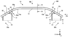
- FIG. 2 is a front view of the bumper structure as viewed in the direction of arrow II in FIG.
- FIG. 3A is a view of the bumper structure viewed in the direction of IIIa in FIG.
- FIG.3 (b) is the figure which looked at the bumper structure in the direction of IIIb of FIG.
- FIG. 4 is a cross-sectional view of the bumper structure reinforcement taken along line IV-IV in FIG.
- FIG. 5 is a cross-sectional view of the energy absorbing member of the bumper structure taken along line VV in FIG.
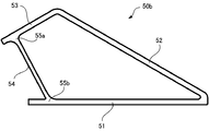
- FIG. 6 is an enlarged view showing an intermediate member of the bumper structure.
- FIG. 1 is a perspective view showing a bumper structure according to an embodiment of the present invention.
- FIG. 2 is a front view of the bumper structure as viewed in the direction of arrow II in FIG.
- FIG. 3A is a view of the bumper structure viewed in the direction of IIIa in FIG.
- FIG. 7A is a front view showing a model of a bumper structure of an example of the present invention used for FEM (Finite Element Method) analysis.
- FIG. 7B is a front view showing a model of the bumper structure of Comparative Example 1.
- FIG. 7C is a front view showing a model of the bumper structure of Comparative Example 2.
- FIG. 8 is a graph of a load-stroke diagram showing the results of FEM analysis of the present invention example, comparative example 1 and comparative example 2.
- the X-axis direction is the vehicle width direction
- the Y-axis direction is the vehicle front-rear direction
- the Z-axis direction is the vehicle height direction.
- the bumper structure 100 is provided on the front side of the vehicle
- the + Y direction is the front of the vehicle.
- the bumper structure 100 includes a reinforcement 10, energy absorbing members 30a and 30b, and intermediate members 50a and 50b.
- the part where each member contacts is joined by a method such as welding.
- Reinforce 10 is formed from an extruded shape of an aluminum alloy having a cross section which will be described later with reference to FIG.
- the reinforcement 10 is formed by bending a linear extruded profile at bent portions 13a and 13b. Thereby, the reinforcement 10 is provided with the linear part 11 and inclination part 12a, 12b of a vehicle outer side, as shown in FIG.
- the energy absorbing members 30a and 30b are called crush cans, and are members that are deformed at the time of collision and absorb collision energy.
- the energy absorbing members 30a and 30b are aluminum alloy members having the same shape, and are arranged symmetrically. Each of the energy absorbing members 30a and 30b is formed of an extruded shape of an aluminum alloy having a cross section described later with reference to FIG.
- the energy absorbing members 30 a and 30 b each include a front end portion 31, an inclined portion 32, and a rear end portion 33.
- the front end portion 31 is located so as to face the outside of the vehicle, and has an end face parallel to the straight portion 11 of the reinforcement 10.
- the inclined portion 32 is continuous from the front end portion 31 and is in contact with the inner sides of the inclined portions 12 a and 12 b of the reinforcement 10.
- the rear end portion 33 is located so as to face the inside of the vehicle, and has an end surface parallel to the straight portion 11 of the reinforcement 10.
- the intermediate members 50a and 50b shown in FIG. 2 are aluminum alloy members having the same shape, and are arranged symmetrically. Each of the intermediate members 50a and 50b includes a first portion 51 and a second portion 52.
- the first portion 51 is a plate-like portion that is in contact with the front end portions 31 of the energy absorbing members 30a and 30b. Therefore, the intermediate members 50a and 50b are located more on the vehicle outer side than the energy absorbing members 30a and 30b.
- the second portion 52 is in contact with the inside of the inclined portions 12 a and 12 b of the reinforcement 10.
- the contact surface between the second portion 52 and the inclined portions 12a and 12b is adjacent to the contact surface between the inclined portion 32 and the inclined portions 12a and 12b.
- the first portion 51 and the second portion 52 are connected at a position close to the inclined portion 32 of the energy absorbing members 30a and 30b. Moreover, the 1st part 51 and the 2nd part 52 are connected by the part demonstrated in FIG. 6 in the edge part vicinity of each other side.
- the energy absorbing members 30 a and 30 b have a width in the Z-axis direction that is slightly smaller than the width of the back plate 15 that is the vehicle inner surface of the reinforcement 10.
- the energy absorbing members 30a and 30b are disposed between the outermost position of the back plate 15 and the position closest to the center of the intermediate members 50a and 50b in the X-axis direction.
- the intermediate members 50a and 50b have a width that is slightly larger than the width of the back plate 15 in the Z-axis direction.
- Reinforce 10 has a cross-sectional shape shown in FIG.
- the reinforcement 10 includes a front plate 14, a back plate 15, connecting plates 16a and 16b, intersection portions 17a and 17b, and intersection portions 18a and 18b.
- the front plate 14 and the back plate 15 are each formed in a plate shape parallel to the Z-axis direction.
- the front plate 14 outside the vehicle has a width that is slightly narrower than the width of the back plate 15 inside the vehicle.
- the back plate 15 has a slightly thinner plate thickness than the front plate 14.
- the front plate 14 and the back plate 15 are connected by connecting plates 16a and 16b at intersections 17a and 17b and intersections 18a and 18b.
- the distance between the intersections 17a and 17b on the front plate 14 side is slightly narrower than the intersections 18a and 18b on the back plate 15 side.
- the connecting plates 16 a and 16 b are slightly thinner than the front plate 14 and slightly thicker than the back plate 15.
- the plate thickness of each member is not limited to this.
- the intersection parts 17a and 17b and the intersection parts 18a and 18b are formed so as to have shapes that are built up on both sides with respect to the plate thickness of the connecting plates 16a and 16b.
- the energy absorbing member 30b has a cross-sectional shape shown in FIG.
- the energy absorbing member 30a also has the same cross-sectional shape as the energy absorbing member 30b.
- the energy absorbing members 30a and 30b include side walls 34a and 34b, side walls 35a and 35b, corner portions 36a, 36b, 36c, and 36d, ribs 37a and 37b, and hollow portions 38a, 38b, and 38c.
- the side walls 34a, 34b, the side walls 35a, 35b, the corners 36a, 36b, 36c, 36d, and the ribs 37a, 37b are all thin plates having the same plate thickness. However, the plate thickness of each member is not limited to this.
- Side walls 34a and 34b are a pair of opposing side walls parallel to the X-axis direction.
- the side walls 35a and 35b are a pair of opposing side walls parallel to the Z-axis direction.
- the side walls 34a and 34b have a width wider than the width of the side walls 35a and 35b. Due to the side walls 34a and 34b and the side walls 35a and 35b, the energy absorbing members 30a and 30b have a substantially rectangular cross section.
- the corner 36a is disposed at the boundary between the side wall 34a and the side wall 35a.
- the corner 36b is disposed at the boundary between the side wall 34a and the side wall 35b.
- the corner portion 36c is disposed at the boundary between the side wall 34b and the side wall 35a.
- the corner 36d is disposed at the boundary between the side wall 34b and the side wall 35b.
- the corners 36a, 36b, 36c, and 36d are disposed so as to be inclined so that the cross-sectional shape of the energy absorbing members 30a and 30b is chamfered at the four corners.
- Side walls 34a and 34b are connected by ribs 37a and 37b at two locations.
- the ribs 37a and 37b are arranged in parallel with the side walls 35a and 35b.
- the ribs 37a and 37b form hollow portions 38a, 38b, and 38c in the cross-sectional shape of the energy absorbing members 30a and 30b.
- the hollow portion 38a and the hollow portion 38c have the same cross-sectional area, and are disposed on the target with respect to the central axis along the Z-axis direction.
- the hollow part 38b between the hollow part 38a and the hollow part 38c has a cross-sectional area slightly smaller than the cross-sectional areas of the hollow parts 38a and 38c.
- the energy absorbing members 30a and 30b have a cross section as shown in FIG. 5 along the Y-axis direction, so that they buckle and deform when the vehicle collides, and absorb the collision energy.
- the intermediate member 50a When the intermediate member 50b shown in FIG. 2 is enlarged, as shown in FIG. 6, a first portion 51, a second portion 52, a third portion 53, a fourth portion 54, and intersection portions 55a and 55b are provided. .
- the intermediate member 50a also includes the same parts as the intermediate member 50b.
- the intermediate members 50a and 50b have a cross section having the shape shown in FIG. 6 along the Z-axis direction that is the height direction of the vehicle.
- the first portion 51 is in contact with the front end portions 31 of the energy absorbing members 30a and 30b. Further, the second portion 52 contacts the inclined portions 12 a and 12 b of the reinforcement 10. Accordingly, the first portion 51 and the second portion 52 are connected to form a predetermined acute angle.
- the third portion 53 is a portion that is continuous with the end portion of the second portion 52 opposite to the first portion 51.
- the second portion 52 and the third portion 53 are connected so as to form a predetermined obtuse angle.
- the third portion 53 and the first portion 51 are connected by the fourth portion 54 at intersections 55a and 55b near the end opposite to the second portion 52.
- the third portion 53 and the fourth portion 54, and the first portion 51 and the fourth portion 54 are connected at an obtuse angle.
- the angle between the first portion 51 and the fourth portion 54 is larger than the angle between the third portion 53 and the fourth portion 54.
- the first portion 51 in contact with the energy absorbing members 30 a and 30 b and the second portion 52 in contact with the reinforcement 10 are connected by the third portion 53 and the fourth portion 54.
- the line lengths of the first part 51 and the second part 52 are formed to be longer than the line lengths of the third part 53 and the fourth part 54.
- the line length of the first portion 51 is equal to the line length of the second portion 52.
- the line length of the third portion 53 is equal to the line length of the fourth portion 54.
- the line lengths need not be the same.
- the line length of the first portion 51 is slightly shorter than the line length of the second portion 52, and the line length of the third portion 53 is slightly shorter than the line length of the fourth portion 54, but is not necessarily limited thereto.
- the first portion 51, the second portion 52, and the third portion 53 all have the same thickness.
- the fourth portion 54 has a slightly thinner plate thickness than the other portions.
- the plate thickness of each member is not limited to this.
- the first portion 51, the second portion 52, the third portion 53, and the fourth portion 54 all have the same width along the Z-axis direction of FIGS. 3 (a) and 3 (b). .
- intermediate members 50a and 50b of extruded shape members are disposed between the reinforcement 10 and the energy absorbing members 30a and 30b.
- the intermediate members 50 a and 50 b suppress stress concentration at the joint between the tip of the inclined energy absorbing members 30 a and 30 b and the reinforcement 10.
- transformation start point of the reinforcement 10 can be provided in the three-way of the intermediate members 50a and 50b, the energy absorption members 30a and 30b, and the reinforcement 10.
- the entire joint between the energy absorbing members 30a and 30b and the reinforcement 10 comes into contact with each other, and load propagation is improved. Therefore, energy absorption can be performed efficiently.
- the first portion 51, the second portion 52, the third portion 53, and the fourth portion 54 are connected so as to form a quadrangle. Further, the angle between the third portion 53 and the fourth portion 54 is larger than the angle between the first portion 51 and the second portion 52. Furthermore, the angle between the second portion 52 and the third portion 53 is equal to the angle between the fourth portion 54 and the first portion 51.
- the cross-sectional characteristics of the energy absorbing members 30a and 30b can be utilized in the load region by the energy absorbing members 30a and 30b. Therefore, according to the present embodiment, in the load-stroke diagram at the time of a vehicle collision, the load received by the energy absorbing member can be raised at an early stage.
- the line length of the first portion 51 is equal to the line length of the second portion 52 in the quadrangle of the intermediate member 50b shown in FIG.
- the line length of the third portion 53 is equal to the line length of the fourth portion 54. That is, in the intermediate members 50a and 50b, the line length of the surface of the first portion 51 in contact with the energy absorbing members 30a and 30b and the line length of the surface of the second portion 52 in contact with the reinforcement 10 are made equal. Thereby, it becomes the deformation
- each member can be freely determined within the scope of the gist of the present invention.
- the bumper structure 100 may be provided on the rear side of the vehicle, and the + Y direction may be the rear of the vehicle.
- FIG. 7 (a) shows a front view of the model of the present invention.
- the bumper structure 100 of the example of the present invention has the structure described in the embodiment.
- FIG. 7B shows a front view of the model of Comparative Example 1.
- the bumper structure 200 of Comparative Example 1 includes energy absorbing members 230a and 230b having shapes different from those of the energy absorbing members 30a and 30b. Further, the bumper structure 200 is not provided with a member corresponding to the intermediate members 50a and 50b. Therefore, the energy absorbing members 230a and 230b do not have a portion corresponding to the front end portion 31 of the energy absorbing members 30a and 30b. An inclined portion 232 is provided in the energy absorbing members 230a and 230b in the entire width direction of FIG.
- Fig. 7 (c) shows a front view of the model of Comparative Example 2.
- the bumper structure 300 of Comparative Example 2 is provided with intermediate members 350a and 350b instead of the intermediate members 50a and 50b.
- Intermediate members 350 a and 350 b include a first portion 351, a second portion 352, and a third portion 353.
- the first portion 351 and the second portion 352 have the same line length as the first portion 51 and the second portion 52 of the intermediate members 50a and 50b.
- the third portion 353 is different from the third portion 53 and the fourth portion 54 of the intermediate members 50a and 50b.
- the third portion 353 is arranged so as to form a triangle in which the angle between the first portion 351 and the second portion 352 is an acute angle close to a right angle.
- the total width in the X-axis direction, which is the vehicle width direction, is 1454 mm
- the total width in the Y-axis direction, which is the vehicle longitudinal direction is 313 mm.
- the reinforcement is made of an aluminum alloy extruded shape.
- the energy absorbing member and the intermediate member were made of a 6000 series aluminum alloy extruded profile having a 0.2% proof stress of 180 MPa.
- the general-purpose finite element analysis software RADIOSS (registered trademark) was used for the FEM analysis.
- the restraint condition of the energy absorbing member end is such that the displacement and rotation other than the crushing direction are restrained and pushed in with a rigid body, assuming that a single plate is installed by welding.
- the analysis results are shown in the load-stroke diagram in FIG.
- the model of the example of the present invention is shown by a solid line.
- the model without the intermediate member of Comparative Example 1 is indicated by a broken line.
- a model in which the intermediate member of Comparative Example 2 is a triangle is indicated by a one-dot chain line.
- the model in which the intermediate members 50a and 50b are rectangular in the bumper structure 100 of the present invention does not buckle or crack in the reinforcement 10. Thereby, it can be set as the stable deformation
- the bumper structure according to the present invention is suitably used as a structural member of a bumper for a vehicle such as an automobile.
Landscapes
- Engineering & Computer Science (AREA)
- Mechanical Engineering (AREA)
- Vibration Dampers (AREA)
- Body Structure For Vehicles (AREA)
Abstract
バンパー構造体(100)は、リインフォース(10)と、エネルギー吸収部材(30a、30b)と、中間部材(50a、50b)と、を備える。リインフォース(10)の傾斜部(12a、12b)は、エネルギー吸収部材(30a、30b)及び中間部材(50a、50b)と接続されている。中間部材(50a、50b)は、エネルギー吸収部材(30a、30b)と接する第1の部分(51)、リインフォース(10)と接する第2の部分(52)、及び、第1の部分(51)と第2の部分(52)とを接続する部分によって、四角形を形成するように接続されている。
Description
本発明は、バンパー構造体に関する。
主に自動車には前部、後部には衝突時の衝撃を吸収するためのバンパー構造体が装備されている。バンパー構造体は、一般的にリインフォース及びエネルギー吸収部材を備える。バンパー構造体は、リインフォースで衝撃を受け、エネルギー吸収部材が変形することにより、車体へのダメージを抑える構造となっている。
現在、前記バンパー構造体は軽量化が求められているが、車両の意匠による制約や、微小ラップ性能などこれまでより多くの機能を求められている。そのためこれまでのバンパー構造体形状よりバンパーリインフォースの意匠曲率半径が小さくなること等が考えられる。バンパーリインフォースの曲率半径が小さくなると前記エネルギー吸収部材の傾斜がつき、衝突の際に、バンパーリインフォースとエネルギー吸収部材先端において、応力集中が起こる。その結果、エネルギー吸収部材の座屈変形前にバンパーリインフォースが座屈又は割れが起こり、効率良くエネルギー吸収できない可能性がある。
特許文献1には、衝突エネルギーを効率良く吸収することを目的として、中間部材を配置したバンパー構造体が提案されている。
特許文献1のバンパー構造体は、リインフォースの座屈を誘発させており、近年要求されているようなより効率のよいエネルギー吸収をすることが難しい。また、リインフォースが座屈することで、バンパーの制御が難しくなるため、後部部品を損傷させる可能性が考えられる。
本発明は、かかる背景に鑑みてなされたものであり、リインフォースの割れ及び座屈を抑制し、効率良くエネルギー吸収できるバンパー構造体を提供することを目的とする。
上記目的を達成するため、本発明の第1の観点に係るバンパー構造体は、
車両の車幅方向に延びたリインフォースと、
車両骨格部と前記リインフォースとを連結するエネルギー吸収部材と、
前記リインフォースと前記エネルギー吸収部材との間に配置され、前記リインフォース及び前記エネルギー吸収部材のそれぞれと接合されている中間部材と、を備え、
前記リインフォースは、前記エネルギー吸収部材及び前記中間部材のそれぞれと接合されている、
ことを特徴とする。
車両の車幅方向に延びたリインフォースと、
車両骨格部と前記リインフォースとを連結するエネルギー吸収部材と、
前記リインフォースと前記エネルギー吸収部材との間に配置され、前記リインフォース及び前記エネルギー吸収部材のそれぞれと接合されている中間部材と、を備え、
前記リインフォースは、前記エネルギー吸収部材及び前記中間部材のそれぞれと接合されている、
ことを特徴とする。
前記中間部材は、
前記エネルギー吸収部材と接合される第1の部分と、
前記リインフォースと接合される第2の部分と、
前記第1の部分と前記第2の部分とを連結する第3の部分及び第4の部分と、を備え、
前記第1の部分、前記第2の部分、前記第3の部分及び前記第4の部分は、四角形が形成されるように接続され、
前記第1の部分と前記第2の部分との間の角度に対して前記第3の部分と前記第4の部分と間の角度が大きく、前記第2の部分と前記第3の部分との間の角度と、前記第4の部分と前記第1の部分との間の角度と、が同等となる、
こととしてもよい。
前記エネルギー吸収部材と接合される第1の部分と、
前記リインフォースと接合される第2の部分と、
前記第1の部分と前記第2の部分とを連結する第3の部分及び第4の部分と、を備え、
前記第1の部分、前記第2の部分、前記第3の部分及び前記第4の部分は、四角形が形成されるように接続され、
前記第1の部分と前記第2の部分との間の角度に対して前記第3の部分と前記第4の部分と間の角度が大きく、前記第2の部分と前記第3の部分との間の角度と、前記第4の部分と前記第1の部分との間の角度と、が同等となる、
こととしてもよい。
前記中間部材は、
前記エネルギー吸収部材と接合される第1の部分と、
前記リインフォースと接合される第2の部分と、
前記第1の部分と前記第2の部分とを連結する第3の部分及び第4の部分と、を備え、
前記第1の部分の線長と前記第2の部分の線長とが同等であり、前記第3の部分の線長と前記第4の部分の線長とが同等である、
こととしてもよい。
前記エネルギー吸収部材と接合される第1の部分と、
前記リインフォースと接合される第2の部分と、
前記第1の部分と前記第2の部分とを連結する第3の部分及び第4の部分と、を備え、
前記第1の部分の線長と前記第2の部分の線長とが同等であり、前記第3の部分の線長と前記第4の部分の線長とが同等である、
こととしてもよい。
本発明によれば、リインフォースの割れ及び座屈を抑制し、効率良くエネルギー吸収できるバンパー構造体を提供することができる。
以下に、本発明の代表的な実施形態を示し、本発明を更に具体的に明らかにすることとする。しかし、本発明が、そのような実施形態の記載によって、何等の制約をも受けるものでないことは、言うまでもないところである。また、本発明には、以下の実施形態の他にも、更には上記した具体的記述以外にも、本発明の趣旨を逸脱しない限りにおいて、当業者の知識に基づいて、種々なる変更、修正、改良等を加え得るものであることが、理解されるべきである。
まず、図1~図4を参照して、主に本実施形態に係るバンパー構造体100の構造について説明する。以下の説明において、X軸方向を車両の車幅方向とし、Y軸方向を車両の前後方向とし、Z軸方向を車両の高さ方向とする。また、バンパー構造体100は車両の前側に設けられており、+Y方向が車両前方であるものとする。
図1に示すように、バンパー構造体100は、リインフォース10と、エネルギー吸収部材30a、30bと、中間部材50a、50bと、を備える。各部材同士が接する箇所は、溶接等の方法により接合される。
リインフォース10は、図4で後述する断面を有するアルミニウム合金の押出形材から形成されている。リインフォース10は、直線状の押出形材が屈曲部13a、13bで曲げられて形成されている。これにより、リインフォース10は、図2に示すように、車両外側の直線部11と傾斜部12a、12bとを備える。
エネルギー吸収部材30a、30bは、クラッシュカンと呼ばれ、衝突時に変形して衝突エネルギーを吸収する部材である。エネルギー吸収部材30a、30bは、同じ形状のアルミニウム合金の部材であり、左右対称に配置されている。エネルギー吸収部材30a、30bは、それぞれ、図5で後述する断面を有するアルミニウム合金の押出形材から形成されている。
図2に示すように、エネルギー吸収部材30a、30bは、それぞれ、前端部31と、傾斜部32と、後端部33とを備える。
前端部31は、車両の外側に向かうように位置しており、リインフォース10の直線部11と並行な端面を有する。
傾斜部32は、前端部31から連続しており、リインフォース10の傾斜部12a、12bの内側に接している。
後端部33は、車両の内側に向かうように位置しており、リインフォース10の直線部11と並行な端面を有する。
図2に示す中間部材50a、50bは、同じ形状のアルミニウム合金の部材であり、左右対称に配置されている。中間部材50a、50bは、それぞれ、第1の部分51と、第2の部分52と、を備える。
第1の部分51は、エネルギー吸収部材30a、30bの前端部31に接している板状の部分である。従って、中間部材50a、50bは、エネルギー吸収部材30a、30bに比べてより車両外側に位置している。
第2の部分52は、リインフォース10の傾斜部12a、12bの内側に接している。第2の部分52と傾斜部12a、12bとの接触面は、傾斜部32と傾斜部12a、12bの接触面と隣接している。
第1の部分51と第2の部分52とは、エネルギー吸収部材30a、30bの傾斜部32に近い位置において接続されている。また、第1の部分51と第2の部分52とは、それぞれの反対側の端部付近において、図6で説明する部分によって連結されている。
図3に示すように、エネルギー吸収部材30a、30bは、リインフォース10の車両内側の面である背面板15の幅よりもやや小さいZ軸方向の幅を有する。また、エネルギー吸収部材30a、30bは、X軸方向において、背面板15の最も外側の位置と、中間部材50a、50bの最も中心寄りの位置と、の間に配置されている。
中間部材50a、50bは、Z軸方向において、背面板15の幅よりもやや大きい幅を有する。
次に、上述の各部材の断面形状等をより詳細に説明する。
リインフォース10は、図4に示す断面形状を有する。リインフォース10は、正面板14と、背面板15と、連結板16a、16bと、交点部17a、17bと、交点部18a、18bと、を備える。
正面板14と背面板15とはそれぞれZ軸方向に平行な板状に形成されている。車両外側の正面板14は、車両内側の背面板15の幅に比べてやや狭い幅を有する。また、背面板15は、正面板14の板厚に比べてやや薄い板厚を有する。
正面板14と背面板15とは、交点部17a、17b及び交点部18a、18bにおいて、連結板16a、16bで連結されている。正面板14側の交点部17a、17bの間隔は、背面板15側の交点部18a、18bに比べてやや狭くなっている。図示の例では、連結板16a、16bの板厚は、正面板14の板厚よりやや薄く、背面板15の板厚よりやや厚い。ただし、各部材の板厚はこれに限定されるものではない。交点部17a、17b及び交点部18a、18bは、連結板16a、16bの板厚に対してそれぞれの両側に肉盛りされた形状となるように形成されている。
エネルギー吸収部材30bは、図5に示す断面形状を有する。エネルギー吸収部材30aもまた、エネルギー吸収部材30bと同じ断面形状を有する。エネルギー吸収部材30a、30bは、側壁34a、34bと、側壁35a、35bと、角部36a、36b、36c、36dと、リブ37a、37bと、中空部38a、38b、38cと、を備える。側壁34a、34b、側壁35a、35b、角部36a、36b、36c、36d、リブ37a、37bは、いずれも同じ板厚を有する薄板である。ただし、各部材の板厚はこれに限定されるものではない。
側壁34a、34bは、X軸方向に平行な対向する一対の側壁である。側壁35a、35bは、Z軸方向平行な対向する一対の側壁である。図5において、側壁34a、34bは、側壁35a、35bの幅よりも広い幅を有する。側壁34a、34b及び側壁35a、35bにより、エネルギー吸収部材30a、30bの断面は、略矩形の断面形状を有する。
角部36aは、側壁34aと側壁35aとの境界部に配置されている。角部36bは、側壁34aと側壁35bとの境界部に配置されている。角部36cは、側壁34bと側壁35aとの境界部に配置されている。角部36dは、側壁34bと側壁35bとの境界部に配置されている。角部36a、36b、36c、36dは、エネルギー吸収部材30a、30bの断面形状を4つの角部で面取りするように、傾斜して配置されている。
側壁34a、34bは、2箇所において、リブ37a、37bで接続されている。リブ37a、37bは、側壁35a、35bと並行に配置されている。リブ37a、37bによって、エネルギー吸収部材30a、30bの断面形状には、中空部38a、38b、38cが形成される。中空部38aと中空部38cとは、同じ断面積を有しており、Z軸方向に沿った中心軸に対して対象に配置されている。中空部38aと中空部38cとの間の中空部38bは、中空部38a、38cの断面積よりやや小さい断面積を有する。
エネルギー吸収部材30a、30bは、Y軸方向に沿って図5のような断面を有することにより、車両の衝突時に座屈変形し、衝突エネルギーを吸収する。
図2に示した中間部材50bを拡大すると、図6に示すように、第1の部分51、第2の部分52、第3の部分53、第4の部分54、交点部55a、55bを備える。中間部材50aもまた、中間部材50bと同様の各部を備える。中間部材50a、50bは、車両の高さ方向であるZ軸方向にそって図6に示した形状の断面を有する。
前述したように、第1の部分51はエネルギー吸収部材30a、30bの前端部31に接する。また、第2の部分52はリインフォース10の傾斜部12a、12bに接する。これに従い、第1の部分51と第2の部分52とは、所定の鋭角をなすように接続されている。
第3の部分53は、第1の部分51とは反対側の第2の部分52の端部に連続している部分である。第2の部分52と第3の部分53とは所定の鈍角をなすように接続されている。
第3の部分53と第1の部分51とは、それぞれの第2の部分52とは反対側の端部の近くの交点部55a、55bにおいて、第4の部分54によって連結されている。第3の部分53と第4の部分54と、及び、第1の部分51と第4の部分54と、はそれぞれ鈍角をなして接続されている。第1の部分51と第4の部分54との間の角度は、第3の部分53と第4の部分54との間の角度よりも大きい。また、第3の部分53と第1の部分51との連結により、第1の部分51、第2の部分52、第3の部分53、第4の部分54は、図5に示す方向において異形の四角形として接続されている。
換言すれば、エネルギー吸収部材30a、30bに接する第1の部分51と、リインフォース10に接する第2の部分52とは、第3の部分53及び第4の部分54によって連結される。
第1の部分51及び第2の部分52の線長は、第3の部分53及び第4の部分54の線長に比べて長くなるように形成されている。第1の部分51の線長は、第2の部分52の線長と同等である。また、第3の部分53の線長は、第4の部分54の線長と同等である。ここで、線長の同等は同一であることを要しない。第1の部分51の線長は第2の部分52の線長よりやや短く、第3の部分53の線長は第4の部分54の線長よりやや短いが、必ずしもこれに限定されない。
第1の部分51、第2の部分52、第3の部分53は、いずれも同一の厚さを有する。第4の部分54は、他の部分に比べてやや薄い板厚を有する。ただし、各部材の板厚はこれに限定されるものではない。また、第1の部分51、第2の部分52、第3の部分53、第4の部分54は、図3(a)、(b)のZ軸方向に沿っていずれも同一の幅を有する。
本実施形態では、リインフォース10とエネルギー吸収部材30a、30bとの間に、押出形材の中間部材50a、50bが配置されている。中間部材50a、50bは、傾斜のついたエネルギー吸収部材30a、30bの先端とリインフォース10との接合部の応力集中を抑制する。これにより、中間部材50a、50b、エネルギー吸収部材30a、30b及びリインフォース10の三差路にリインフォース10の変形の起点を設けることができる。加えて、エネルギー吸収部材30a、30bとリインフォース10との接合部の全体が接触し、荷重伝播が良好となる。そのため、エネルギー吸収を効率良く行うことができる。
本実施形態では、第1の部分51、第2の部分52、第3の部分53及び第4の部分54は、四角形が形成されるように接続されている。また、第1の部分51と第2の部分52との間の角度に対して第3の部分53と第4の部分54と間の角度が大きい。さらに、第2の部分52と第3の部分53との間の角度と、第4の部分54と第1の部分51との間の角度と、が同等となる。これにより、低荷重での変形が容易となるため、エネルギー吸収部材30a、30bによる荷重領域において、エネルギー吸収部材30a、30bの持つ断面特性を活かすことができる。従って、本実施形態によれば、車両衝突時の荷重-ストローク線図において、エネルギー吸収部材の受ける荷重を早期に立ち上げることができる。
本実施形態では、図6に示す中間部材50bの四角形において、第1の部分51の線長と第2の部分52の線長とが同等である。また、第3の部分53の線長と第4の部分54の線長とが同等である。即ち、中間部材50a、50bにおいて、エネルギー吸収部材30a、30bと接する第1の部分51の面の線長と、リインフォース10と接する第2の部分52の面の線長と、を同等としている。これにより、いわゆる肉だまりを起こさずに中間部材50a、50bが折り畳まれる変形となる。従って、一部分に応力集中することがなく、エネルギー吸収部材30a、30bのより広い面に荷重伝播が可能となることから、よりエネルギー吸収の効率を高めることができる。
なお、上述した板厚の他、各部材の寸法については、本発明の趣旨の範囲内で自由に定めることができる。
また、バンパー構造体100が車両の後側に設けられており、+Y方向が車両後方であってもよい。
以下に、本発明の代表的な実施例を示し、本発明を更に具体的に明らかにする。ただし、これらの実施例により本発明が限定されるものではない。
図7(a)に、本発明例のモデルの正面図を示す。本発明例のバンパー構造体100は、実施形態で説明した構造を有する。
図7(b)に、比較例1のモデルの正面図を示す。比較例1のバンパー構造体200は、エネルギー吸収部材30a、30bと異なる形状のエネルギー吸収部材230a、230bを備える。また、バンパー構造体200には、中間部材50a、50bに相当するものが設けられていない。そのため、エネルギー吸収部材230a、230bは、エネルギー吸収部材30a、30bの前端部31に相当する部分がない。図7(b)の幅方向の全体においてエネルギー吸収部材230a、230bに傾斜部232が設けられている。
図7(c)に、比較例2のモデルの正面図を示す。比較例2のバンパー構造体300は、中間部材50a、50bに代えて、中間部材350a、350bが設けられている。
中間部材350a、350bは、第1の部分351と、第2の部分352と、第3の部分353と、を備える。第1の部分351、第2の部分352は、中間部材50a、50bの第1の部分51、第2の部分52と同等の線長を有する。第3の部分353は、中間部材50a、50bの第3の部分53及び第4の部分54とは異なる。第3の部分353は、第1の部分351と第2の部分352との間の角度が直角に近い鋭角になる三角形を形成するように配置されている。
図7(a)~(c)の各モデルにおいて、車幅方向であるX軸方向の全幅を1454mmとし、車両前後方向であるY軸方向の全幅は313mmとした。
本発明例のモデル、並びに、本発明の範囲から外れる比較例1及び比較例2のモデルについて、車両のフルラップ前面衝突を想定したFEM解析を実施した。
FEM解析の材料モデルにおいて、リインフォースについては、アルミニウム合金押出形材からなるものとした。エネルギー吸収部材及び中間部材については、0.2%耐力が180MPaの6000系アルミニウム合金押出形材からなるものとした。
FEM解析には、汎用の有限要素解析ソフトRADIOSS(登録商標)を用いた。エネルギー吸収部材端部の拘束条件は、単板を溶接で設置する場合を想定して、圧壊方向以外の変位と回転を拘束し、剛体で押し込む態様とした。
解析結果を図8に荷重-ストローク線図で示す。本発明例のモデルを実線で示している。比較例1の中間部材なしのモデルを破線で示している。比較例2の中間部材を三角形としたモデルを一点鎖線で示している。
比較例1及び比較例2では、いずれも、ストローク中期のエネルギー吸収部材領域で急激に荷重が増加し、その後低下している。
比較例1及び比較例2の荷重-ストローク線図の結果から、ストローク中期のエネルギー吸収部材領域において、共にバンパーリインフォースの縦壁部で変形、割れが生じる。このようにエネルギー吸収部材の座屈前にバンパーリインフォースが座屈や割れが生じると、変形後期の安定的なエネルギー吸収が困難となる。
これに対し、本発明例では、ストローク中期のエネルギー吸収部材領域での急激な荷重増加及び荷重低下は見られず、安定した荷重-ストローク線図となっている。
この荷重-ストローク線図の結果から、本発明例のバンパー構造体100で中間部材50a、50bを四角形としたモデルは、リインフォース10での座屈や割れはない。これにより、ストローク後期まで安定した変形とすることができている。このような中間部材50a、50bとすることで、応力伝播を円滑に行うことができている結果となった。
本発明は、本発明の広義の精神と範囲を逸脱することなく、様々な実施の形態及び変形が可能とされるものである。また、上述した実施の形態は、この発明を説明するためのものであり、本発明の範囲を限定するものではない。すなわち、本発明の範囲は、実施の形態ではなく、特許請求の範囲によって示される。そして、特許請求の範囲内及びそれと同等の発明の意義の範囲内で施される様々な変形が、この発明の範囲内とみなされる。
本出願は、2018年3月30日に出願された日本国特許出願特願2018-068241号に基づく。本明細書中に、日本国特許出願特願2018-068241号の明細書、特許請求の範囲、図面全体を参照として取り込むものとする。
本発明に係るバンパー構造体は、自動車等の車両用バンパーの構成部材として好適に用いられる。
10 リインフォース
11 直線部
12a、12b 傾斜部
13a、13b 屈曲部
14 正面板
15 背面板
16a、16b 連結板
17a、17b 交点部
18a、18b 交点部
30a、30b、230a、230b エネルギー吸収部材
31 前端部
32、232 傾斜部
33 後端部
34a、34b 側壁
35a、35b 側壁
36a、36b、36c、36d 角部
37a、37b リブ
38a、38b、38c 中空部
50a、50b、350a、350b 中間部材
51、351 第1の部分
52、352 第2の部分
53、353 第3の部分
54 第4の部分
55a、55b 交点部
100、200、300 バンパー構造体
11 直線部
12a、12b 傾斜部
13a、13b 屈曲部
14 正面板
15 背面板
16a、16b 連結板
17a、17b 交点部
18a、18b 交点部
30a、30b、230a、230b エネルギー吸収部材
31 前端部
32、232 傾斜部
33 後端部
34a、34b 側壁
35a、35b 側壁
36a、36b、36c、36d 角部
37a、37b リブ
38a、38b、38c 中空部
50a、50b、350a、350b 中間部材
51、351 第1の部分
52、352 第2の部分
53、353 第3の部分
54 第4の部分
55a、55b 交点部
100、200、300 バンパー構造体
Claims (3)
- 車両の車幅方向に延びたリインフォースと、
車両骨格部と前記リインフォースとを連結するエネルギー吸収部材と、
前記リインフォースと前記エネルギー吸収部材との間に配置され、前記リインフォース及び前記エネルギー吸収部材のそれぞれと接合されている中間部材と、を備え、
前記リインフォースは、前記エネルギー吸収部材及び前記中間部材のそれぞれと接合されている、
ことを特徴とするバンパー構造体。 - 前記中間部材は、
前記エネルギー吸収部材と接合される第1の部分と、
前記リインフォースと接合される第2の部分と、
前記第1の部分と前記第2の部分とを連結する第3の部分及び第4の部分と、を備え、
前記第1の部分、前記第2の部分、前記第3の部分及び前記第4の部分は、四角形が形成されるように接続され、
前記第1の部分と前記第2の部分との間の角度に対して前記第3の部分と前記第4の部分と間の角度が大きく、前記第2の部分と前記第3の部分との間の角度と、前記第4の部分と前記第1の部分との間の角度と、が同等となる、
ことを特徴とする請求項1に記載のバンパー構造体。 - 前記中間部材は、
前記エネルギー吸収部材と接合される第1の部分と、
前記リインフォースと接合される第2の部分と、
前記第1の部分と前記第2の部分とを連結する第3の部分及び第4の部分と、を備え、
前記第1の部分の線長と前記第2の部分の線長とが同等であり、前記第3の部分の線長と前記第4の部分の線長とが同等である、
ことを特徴とする請求項1に記載のバンパー構造体。
Priority Applications (2)
| Application Number | Priority Date | Filing Date | Title |
|---|---|---|---|
| US17/041,863 US11007957B2 (en) | 2018-03-30 | 2019-03-29 | Bumper structural body |
| CN201980023551.0A CN112004723B (zh) | 2018-03-30 | 2019-03-29 | 保险杠构造体 |
Applications Claiming Priority (2)
| Application Number | Priority Date | Filing Date | Title |
|---|---|---|---|
| JP2018-068241 | 2018-03-30 | ||
| JP2018068241A JP6581686B1 (ja) | 2018-03-30 | 2018-03-30 | バンパー構造体 |
Publications (1)
| Publication Number | Publication Date |
|---|---|
| WO2019189804A1 true WO2019189804A1 (ja) | 2019-10-03 |
Family
ID=68053615
Family Applications (1)
| Application Number | Title | Priority Date | Filing Date |
|---|---|---|---|
| PCT/JP2019/014120 Ceased WO2019189804A1 (ja) | 2018-03-30 | 2019-03-29 | バンパー構造体 |
Country Status (4)
| Country | Link |
|---|---|
| US (1) | US11007957B2 (ja) |
| JP (1) | JP6581686B1 (ja) |
| CN (1) | CN112004723B (ja) |
| WO (1) | WO2019189804A1 (ja) |
Families Citing this family (5)
| Publication number | Priority date | Publication date | Assignee | Title |
|---|---|---|---|---|
| DE102015117700A1 (de) * | 2015-10-16 | 2017-04-20 | Magna International Inc. | Querträger und Verfahren zur Herstellung eines Querträgers |
| JP7084326B2 (ja) * | 2019-01-11 | 2022-06-14 | トヨタ自動車株式会社 | クラッシュボックス |
| DE102019105188A1 (de) * | 2019-02-28 | 2020-09-03 | Böllhoff Verbindungstechnik GmbH | Aufprallschutzverstärkung einer Fahrzeugkonstruktion sowie Verbindungs- und Herstellungsverfahren dafür |
| JP7044828B2 (ja) | 2020-05-27 | 2022-03-30 | 本田技研工業株式会社 | 車体前部構造 |
| CN112622796A (zh) * | 2020-12-10 | 2021-04-09 | 蒋世宾 | 一种新式腔体汽车防撞梁吸能盒 |
Citations (3)
| Publication number | Priority date | Publication date | Assignee | Title |
|---|---|---|---|---|
| JP5180950B2 (ja) * | 2009-12-21 | 2013-04-10 | 株式会社神戸製鋼所 | バンパー構造体 |
| KR20150104900A (ko) * | 2014-03-07 | 2015-09-16 | 한화첨단소재 주식회사 | 충돌성능을 만족하는 알루미늄 크래쉬박스 |
| JP2017087928A (ja) * | 2015-11-09 | 2017-05-25 | 本田技研工業株式会社 | 車体前部構造 |
Family Cites Families (37)
| Publication number | Priority date | Publication date | Assignee | Title |
|---|---|---|---|---|
| ATE240858T1 (de) * | 2000-08-10 | 2003-06-15 | Benteler Werke Ag | Zweischalig gebildeter träger mit offenem profil für einen stossfänger |
| JP4048080B2 (ja) * | 2001-07-30 | 2008-02-13 | アイシン精機株式会社 | 車両用バンパ装置及びバンパステー |
| JP4251562B2 (ja) * | 2004-07-20 | 2009-04-08 | 本田技研工業株式会社 | 車両用バンパビーム |
| EP1923273B1 (en) * | 2005-09-09 | 2010-12-01 | Toyoda Iron Works Co., Ltd. | Impact absorption member for vehicle |
| JP4623071B2 (ja) * | 2007-09-21 | 2011-02-02 | トヨタ自動車株式会社 | バンパ取付部構造 |
| JP2013169866A (ja) * | 2012-02-20 | 2013-09-02 | Toyota Motor Corp | 車体前部構造 |
| JP5692191B2 (ja) * | 2012-09-14 | 2015-04-01 | トヨタ自動車株式会社 | 車体前部構造 |
| JP5692210B2 (ja) * | 2012-12-07 | 2015-04-01 | トヨタ自動車株式会社 | 車体前部構造 |
| JP5761214B2 (ja) * | 2013-01-18 | 2015-08-12 | トヨタ自動車株式会社 | 車体前部構造 |
| WO2014162574A1 (ja) * | 2013-04-04 | 2014-10-09 | トヨタ自動車株式会社 | 車体端部構造 |
| CN105555455B (zh) * | 2013-04-19 | 2018-10-26 | 麦格纳国际公司 | 异种材料的接合 |
| JP6070837B2 (ja) * | 2013-05-27 | 2017-02-08 | トヨタ自動車株式会社 | 車体前部構造 |
| JP5924308B2 (ja) * | 2013-06-03 | 2016-05-25 | トヨタ自動車株式会社 | 車体前部構造 |
| JP5858006B2 (ja) * | 2013-06-28 | 2016-02-10 | トヨタ自動車株式会社 | 自動車の車体前部構造 |
| US9067549B2 (en) * | 2013-07-17 | 2015-06-30 | Ford Global Technologies, Llc | Collision deflector assembly |
| DE102014222949A1 (de) * | 2013-11-18 | 2015-05-21 | Ford Global Technologies, Llc | Flexibler elektroresisitiver Aufprallerkennungssensor für am vorderen 'Träger befestigten Airbag |
| JP6107747B2 (ja) * | 2014-06-02 | 2017-04-05 | トヨタ自動車株式会社 | 歩行者衝突検知センサを備えた車両前部構造 |
| DE102014216478A1 (de) * | 2014-08-20 | 2016-02-25 | Bayerische Motoren Werke Aktiengesellschaft | Karosserieanordnung für ein Kraftfahrzeug, die insbesondere für eine Kollision mit geringer Überdeckung ausgebildet ist |
| JP6186341B2 (ja) * | 2014-11-28 | 2017-08-23 | 豊田鉄工株式会社 | 車体前部構造 |
| US9517799B2 (en) * | 2015-04-28 | 2016-12-13 | Toyota Jidosha Kabushiki Kaisha | Vehicle front portion structure |
| JP6178361B2 (ja) * | 2015-05-12 | 2017-08-09 | トヨタ自動車株式会社 | 車両前部構造 |
| US9669785B2 (en) * | 2015-08-26 | 2017-06-06 | Toyota Motor Engineering & Manufacturing North America, Inc. | Bumper assemblies including spacer members and vehicles incorporating the same |
| EP3444146B1 (en) * | 2016-04-15 | 2020-04-08 | Nissan Motor Co., Ltd. | Energy absorption structure |
| EP3300955B1 (en) * | 2016-09-30 | 2019-02-06 | Ningbo Geely Automobile Research & Development Co., Ltd. | Module for a crash management system |
| KR102429004B1 (ko) * | 2016-12-15 | 2022-08-03 | 현대자동차 주식회사 | 스몰 오버랩 충돌에 대응하는 차체 보강구조 |
| JP6769390B2 (ja) * | 2017-05-16 | 2020-10-14 | トヨタ自動車株式会社 | 車両前部構造 |
| DE102017118514B3 (de) * | 2017-08-14 | 2019-01-17 | Kirchhoff Automotive Deutschland Gmbh | Stoßfängerquerträger |
| US10464609B2 (en) * | 2017-11-14 | 2019-11-05 | Fca Us Llc | Small overlap impact countermeasure for vehicle |
| JP6943164B2 (ja) * | 2017-12-08 | 2021-09-29 | トヨタ自動車株式会社 | バンパリンフォース取付構造 |
| JP6562064B2 (ja) * | 2017-12-14 | 2019-08-28 | マツダ株式会社 | 車両の衝撃吸収構造 |
| JP7031356B2 (ja) * | 2018-02-19 | 2022-03-08 | トヨタ自動車株式会社 | 車両前部構造 |
| JP7052459B2 (ja) * | 2018-03-22 | 2022-04-12 | トヨタ自動車株式会社 | 車両骨格構造 |
| KR20190131966A (ko) * | 2018-05-18 | 2019-11-27 | 현대자동차주식회사 | 범퍼 어셈블리 및 그것의 제조 방법 |
| JP7035908B2 (ja) * | 2018-08-29 | 2022-03-15 | トヨタ自動車株式会社 | 車両前部構造 |
| JP7124728B2 (ja) * | 2019-01-25 | 2022-08-24 | トヨタ自動車株式会社 | 車両構造 |
| DE102019104565B4 (de) * | 2019-02-22 | 2022-12-01 | Benteler Automobiltechnik Gmbh | Stoßfängeranordnung für ein Kraftfahrzeug |
| JP7115414B2 (ja) * | 2019-05-08 | 2022-08-09 | トヨタ自動車株式会社 | 車両前部構造 |
-
2018
- 2018-03-30 JP JP2018068241A patent/JP6581686B1/ja active Active
-
2019
- 2019-03-29 US US17/041,863 patent/US11007957B2/en active Active
- 2019-03-29 WO PCT/JP2019/014120 patent/WO2019189804A1/ja not_active Ceased
- 2019-03-29 CN CN201980023551.0A patent/CN112004723B/zh active Active
Patent Citations (3)
| Publication number | Priority date | Publication date | Assignee | Title |
|---|---|---|---|---|
| JP5180950B2 (ja) * | 2009-12-21 | 2013-04-10 | 株式会社神戸製鋼所 | バンパー構造体 |
| KR20150104900A (ko) * | 2014-03-07 | 2015-09-16 | 한화첨단소재 주식회사 | 충돌성능을 만족하는 알루미늄 크래쉬박스 |
| JP2017087928A (ja) * | 2015-11-09 | 2017-05-25 | 本田技研工業株式会社 | 車体前部構造 |
Also Published As
| Publication number | Publication date |
|---|---|
| JP2019177772A (ja) | 2019-10-17 |
| US20210046889A1 (en) | 2021-02-18 |
| US11007957B2 (en) | 2021-05-18 |
| JP6581686B1 (ja) | 2019-09-25 |
| CN112004723A (zh) | 2020-11-27 |
| CN112004723B (zh) | 2021-05-04 |
Similar Documents
| Publication | Publication Date | Title |
|---|---|---|
| WO2019189804A1 (ja) | バンパー構造体 | |
| JP4738474B2 (ja) | 車両用衝撃吸収部材 | |
| US8066322B2 (en) | Vehicle body structure | |
| CN103796905A (zh) | 骨架构件 | |
| JP6703322B1 (ja) | 自動車骨格部材および電気自動車 | |
| US20090079210A1 (en) | Bumper attachment portion structure | |
| JP5353209B2 (ja) | 衝撃吸収部材 | |
| JP6973646B2 (ja) | 高衝突性能を有する閉断面構造材および自動車の車体骨格 | |
| CN107107849B (zh) | 车身前部构造 | |
| JP2024541373A (ja) | 車両用サイドシル | |
| JP5207228B2 (ja) | 車両用インナパネル | |
| JP5235007B2 (ja) | クラッシュボックス | |
| JP7568928B2 (ja) | 衝撃吸収部材 | |
| JP5056545B2 (ja) | 車両用バンパの取付構造 | |
| CN116568568A (zh) | 汽车的车身下部构造 | |
| JP7264597B2 (ja) | 車両用構造部材及び車両 | |
| JP7376797B2 (ja) | 自動車骨格部材および電気自動車 | |
| JP5585684B2 (ja) | 衝撃吸収部材 | |
| JP6747928B2 (ja) | 衝撃吸収部材 | |
| CN116710332B (zh) | 构造构件 | |
| WO2020085383A1 (ja) | 自動車骨格部材および電気自動車 | |
| JP6687179B1 (ja) | 自動車骨格部材および電気自動車 | |
| EP3604086B1 (en) | Shock-absorbing member and side member of automobile | |
| JP2006205933A (ja) | 車両の衝撃吸収構造 | |
| JP6269628B2 (ja) | 車両用バンパ構造 |
Legal Events
| Date | Code | Title | Description |
|---|---|---|---|
| 121 | Ep: the epo has been informed by wipo that ep was designated in this application |
Ref document number: 19775594 Country of ref document: EP Kind code of ref document: A1 |
|
| DPE2 | Request for preliminary examination filed before expiration of 19th month from priority date (pct application filed from 20040101) | ||
| 122 | Ep: pct application non-entry in european phase |
Ref document number: 19775594 Country of ref document: EP Kind code of ref document: A1 |