WO2019159746A1 - 端子、及び端子付き電線 - Google Patents
端子、及び端子付き電線 Download PDFInfo
- Publication number
- WO2019159746A1 WO2019159746A1 PCT/JP2019/003954 JP2019003954W WO2019159746A1 WO 2019159746 A1 WO2019159746 A1 WO 2019159746A1 JP 2019003954 W JP2019003954 W JP 2019003954W WO 2019159746 A1 WO2019159746 A1 WO 2019159746A1
- Authority
- WO
- WIPO (PCT)
- Prior art keywords
- electric wire
- terminal
- slide
- pressing
- wire
- Prior art date
- Legal status (The legal status is an assumption and is not a legal conclusion. Google has not performed a legal analysis and makes no representation as to the accuracy of the status listed.)
- Ceased
Links
Images


Classifications
-
- H—ELECTRICITY
- H01—ELECTRIC ELEMENTS
- H01R—ELECTRICALLY-CONDUCTIVE CONNECTIONS; STRUCTURAL ASSOCIATIONS OF A PLURALITY OF MUTUALLY-INSULATED ELECTRICAL CONNECTING ELEMENTS; COUPLING DEVICES; CURRENT COLLECTORS
- H01R4/00—Electrically-conductive connections between two or more conductive members in direct contact, i.e. touching one another; Means for effecting or maintaining such contact; Electrically-conductive connections having two or more spaced connecting locations for conductors and using contact members penetrating insulation
- H01R4/10—Electrically-conductive connections between two or more conductive members in direct contact, i.e. touching one another; Means for effecting or maintaining such contact; Electrically-conductive connections having two or more spaced connecting locations for conductors and using contact members penetrating insulation effected solely by twisting, wrapping, bending, crimping, or other permanent deformation
- H01R4/18—Electrically-conductive connections between two or more conductive members in direct contact, i.e. touching one another; Means for effecting or maintaining such contact; Electrically-conductive connections having two or more spaced connecting locations for conductors and using contact members penetrating insulation effected solely by twisting, wrapping, bending, crimping, or other permanent deformation by crimping
-
- H—ELECTRICITY
- H01—ELECTRIC ELEMENTS
- H01R—ELECTRICALLY-CONDUCTIVE CONNECTIONS; STRUCTURAL ASSOCIATIONS OF A PLURALITY OF MUTUALLY-INSULATED ELECTRICAL CONNECTING ELEMENTS; COUPLING DEVICES; CURRENT COLLECTORS
- H01R4/00—Electrically-conductive connections between two or more conductive members in direct contact, i.e. touching one another; Means for effecting or maintaining such contact; Electrically-conductive connections having two or more spaced connecting locations for conductors and using contact members penetrating insulation
- H01R4/28—Clamped connections, spring connections
- H01R4/50—Clamped connections, spring connections utilising a cam, wedge, cone or ball also combined with a screw
- H01R4/5083—Clamped connections, spring connections utilising a cam, wedge, cone or ball also combined with a screw using a wedge
-
- H—ELECTRICITY
- H01—ELECTRIC ELEMENTS
- H01B—CABLES; CONDUCTORS; INSULATORS; SELECTION OF MATERIALS FOR THEIR CONDUCTIVE, INSULATING OR DIELECTRIC PROPERTIES
- H01B7/00—Insulated conductors or cables characterised by their form
-
- H—ELECTRICITY
- H01—ELECTRIC ELEMENTS
- H01R—ELECTRICALLY-CONDUCTIVE CONNECTIONS; STRUCTURAL ASSOCIATIONS OF A PLURALITY OF MUTUALLY-INSULATED ELECTRICAL CONNECTING ELEMENTS; COUPLING DEVICES; CURRENT COLLECTORS
- H01R13/00—Details of coupling devices of the kinds covered by groups H01R12/70 or H01R24/00 - H01R33/00
- H01R13/02—Contact members
- H01R13/26—Pin or blade contacts for sliding co-operation on one side only
-
- H—ELECTRICITY
- H01—ELECTRIC ELEMENTS
- H01R—ELECTRICALLY-CONDUCTIVE CONNECTIONS; STRUCTURAL ASSOCIATIONS OF A PLURALITY OF MUTUALLY-INSULATED ELECTRICAL CONNECTING ELEMENTS; COUPLING DEVICES; CURRENT COLLECTORS
- H01R4/00—Electrically-conductive connections between two or more conductive members in direct contact, i.e. touching one another; Means for effecting or maintaining such contact; Electrically-conductive connections having two or more spaced connecting locations for conductors and using contact members penetrating insulation
- H01R4/24—Connections using contact members penetrating or cutting insulation or cable strands
- H01R4/2491—Connections using contact members penetrating or cutting insulation or cable strands the contact members penetrating the insulation being actuated by conductive cams or wedges
-
- H—ELECTRICITY
- H01—ELECTRIC ELEMENTS
- H01R—ELECTRICALLY-CONDUCTIVE CONNECTIONS; STRUCTURAL ASSOCIATIONS OF A PLURALITY OF MUTUALLY-INSULATED ELECTRICAL CONNECTING ELEMENTS; COUPLING DEVICES; CURRENT COLLECTORS
- H01R4/00—Electrically-conductive connections between two or more conductive members in direct contact, i.e. touching one another; Means for effecting or maintaining such contact; Electrically-conductive connections having two or more spaced connecting locations for conductors and using contact members penetrating insulation
- H01R4/28—Clamped connections, spring connections
- H01R4/48—Clamped connections, spring connections utilising a spring, clip, or other resilient member
Definitions
- the technology disclosed in this specification relates to a terminal and an electric wire with a terminal.
- a terminal connected to a core wire exposed from the end of an electric wire is known.
- This terminal includes a crimping portion that crimps the core wire exposed from the end of the electric wire from the outside.
- a terminal having a predetermined shape is formed by pressing a metal plate material.
- a terminal is mounted on the mounting part of the lower mold located on the lower side of the pair of molds that can move in the vertical direction.
- the core wire exposed from the end of the electric wire is placed over the crimping portion of the terminal.
- one or both of the pair of molds are moved in a direction approaching each other, and the crimping part is sandwiched between the crimping part of the upper mold and the mounting part of the lower mold, thereby fixing the crimping part to the core wire of the electric wire.
- Crimp to. the terminal is connected to the end of the electric wire (see Patent Document 1).
- a terminal having a pair of clamping parts for clamping the electric wire is conceivable.
- a core wire is disposed between the pair of holding portions of the terminal, and a slide member having a pressing portion that presses the pair of holding portions toward the core wire is slid from the direction in which the electric wire is led out from the terminal.
- the pressing part pressed the pair of holding parts toward the core wire, and the pair of holding parts was expected to connect the terminal and the electric wire by holding the core wire.
- the technology disclosed in the present specification has been completed based on the above situation, and aims to improve the efficiency of the connection work between the terminal and the electric wire.
- the technology disclosed in the present specification is a terminal connected to a terminal of an electric wire, and has a base, an electric wire having a holding portion that extends from the base along the extending direction and holds the electric wire.
- a connecting portion and a plurality of pressing portions that are movable with respect to the electric wire connecting portion along the extending direction and press the holding portion toward the electric wire by contacting the holding portion.
- the plurality of pressing portions are formed so as to protrude toward the clamping portion, and are formed side by side in a direction intersecting the extending direction. .
- the technology disclosed in the present specification is a terminal-attached electric wire that includes the terminal and an electric wire connected to the terminal.
- the tips of the plurality of pressing parts are in contact with the clamping parts, respectively.
- the part which a press part contacts with a clamping part is disperse
- the slide part can be easily moved in the extending direction, so that the efficiency of the connection work between the terminal and the electric wire can be improved.
- the pressing portion is formed to extend along the extending direction.
- the slide portion can be moved more smoothly than in the case where the plurality of pressing portions are discretely formed along the extending direction. Thereby, the efficiency of the connection work of a terminal and an electric wire can be improved further.
- the electric wire is arranged between adjacent pressing portions among the plurality of pressing portions.
- the sandwiching portion pressed by the plurality of pressing portions is deformed along the outer shape of the electric wire, the deformation amount of the sandwiching portion can be suppressed. As a result, the pressing force necessary for deforming the clamping portion is reduced, so that the slide portion can be easily moved in the extending direction. As a result, the efficiency of the connection work between the terminal and the electric wire can be further improved.
- the efficiency of the connection work between the terminal and the electric wire can be improved.
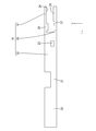
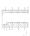
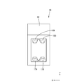
- the exploded perspective view which shows the electric wire and female terminal based on Embodiment 1 The perspective view which shows the connection cylinder part, extension part, and electric wire connection part of a female terminal Side view of female terminal, showing connection tube, extension, and wire connection Rear view of female terminal, showing connection tube, extension, and wire connection Sectional drawing which shows the connection cylinder part, extension part, and electric wire connection part of a female terminal Partially enlarged sectional view showing the wire connection part Perspective view showing the slide part Rear view showing slide part
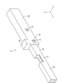
- Perspective view showing electric wire with terminal Sectional view showing the electric wire with terminal XV-XV sectional view in FIG.
- the electric wire with terminal 10 includes an electric wire 11 and a female terminal 12 (an example of a terminal) connected to the electric wire 11.
- symbol may be attached
- the electric wire 11 includes a core wire 13 and an insulating coating 35 made of an insulating synthetic resin that covers the outer periphery of the core wire 13.
- a metal which comprises the core wire 13 it can select suitably from arbitrary metals as needed, such as copper, a copper alloy, aluminum, an aluminum alloy.
- the core wire 13 according to the present embodiment is made of copper or a copper alloy.
- the core wire 13 may be a stranded wire formed by twisting a plurality of metal strands, or may be a single core wire made of one rod-shaped metal material.
- the core wire 13 which concerns on this embodiment consists of a single core wire.
- the female terminal 12 has an electric wire connection having a first holding part 14 (an example of a holding part) and a second holding part 15 (an example of a holding part) that hold the core wire 13 of the electric wire 11.
- a slide part 18 provided with
- the female terminal 12 is made of a conductive metal material.
- a metal which comprises a terminal it can select suitably from arbitrary metals as needed, such as copper, copper alloy, aluminum, aluminum alloy.
- the terminal according to the present embodiment is made of copper or a copper alloy.
- the female terminal 12 can be formed by a known method such as cutting, casting, or pressing.
- the female terminal 12 has a connecting cylinder portion 20 into which a male terminal (not shown) is inserted.
- the connecting tube portion 20 has a rectangular tube shape extending in the front-rear direction.
- the connecting cylinder part 20 is open forward and backward.
- An elastic connection piece (not shown) that elastically contacts the male terminal is disposed inside the connection cylinder portion 20. The elastic connection piece elastically contacts the male terminal, whereby the male terminal and the female terminal 12 are electrically connected.
- the rear end portion of the connecting tube portion 20 is connected to an extending portion 21 extending rearward.
- the wire connecting portion 19 is connected to the rear end portion of the extending portion 21.
- the electric wire connecting portion 19 includes a base portion 22 and a first holding portion 14 and a second holding portion 15 that extend rearward (an example of the extending direction) from the rear end portion of the base portion 22.
- the extended portion 21 is formed to open upward. Thereby, the core wire 13 arranged inside the extending portion 21 can be viewed from above.
- the base 22 has a rectangular tube shape extending in the front-rear direction.
- the base 22 opens forward and backward.
- the first clamping portion 14 extends rearward (an example of the extending direction) from the rear end portion of the upper wall of the base portion 22.
- the 1st clamping part 14 has comprised the plate shape elongated in the front-back direction.
- the 1st clamping part 14 is formed so that bending deformation is possible about the plate
- the lower surface of the first clamping unit 14 is a first contact surface 24 that contacts the core wire 13.
- a first protrusion 25 that protrudes downward from the first contact surface 24 is formed at a position near the front end of the first sandwiching portion 14.
- a plurality of first serrations 26 that extend in the left-right direction and are arranged at intervals in the front-rear direction in the first contact surface 24 of the first holding portion 14 at a position behind the first protrusion 25 are V-shaped grooves. (See FIG. 6).
- the second sandwiching portion 15 extends backward (an example of the extending direction) from the rear end portion of the lower wall of the base portion 22.
- the 2nd clamping part 15 has comprised the plate shape elongated in the front-back direction.
- the 2nd clamping part 15 is formed so that bending deformation is possible about a plate
- the upper surface of the second clamping unit 15 is a second contact surface 27 that contacts the core wire 13.
- a second protrusion 28 protruding upward from the second contact surface 27 is provided on the second contact surface 27 of the second sandwiching portion 15 at a position rearward of the rear end portion of the first protrusion of the first sandwiching portion 14. Is formed.
- On the upper surface of the second protrusion 28, a plurality of second serrations 29 extending in the left-right direction and arranged at intervals in the front-rear direction are formed in a V-shaped groove shape (see FIG. 6).
- the slide part 18 has a rectangular tube shape elongated in the front-rear direction, and is open in the front-rear direction.
- the opening on the front side of the slide portion 18 is formed to be the same as or slightly larger than the outer shape of the wire connection portion 19, and the wire connection portion 19 can be inserted.
- the slide portion 18 can be formed of any material such as metal, synthetic resin, ceramic, or the like as necessary.
- a metal which comprises the slide part 18 arbitrary metals can be suitably selected as needed, such as copper, copper alloy, aluminum, aluminum alloy, and stainless steel.
- the slide portion 18 is formed of a metal, it can be formed by any method as necessary, such as cutting, casting, or pressing.
- a jig contact portion 30 protruding upward is provided at the front end portion of the upper wall of the slide portion 18.
- the slide portion 18 slides forward.
- a temporary locking portion 31 to be held is provided.
- the temporary locking portion 31 is formed as a through-hole penetrating the left side wall and the right side wall of the slide portion 18.
- the size of the hole edge of the temporary locking portion 31 is the same as or slightly larger than that of the locking projection 23, and the locking projection 23 can be fitted into the temporary locking portion 31.
- the left side wall and the right side wall of the slide part 18 are elastically locked to the locking protrusions 23 behind the temporary locking part 31, respectively.
- a main locking portion 32 that is held at the locking position is provided.
- the main locking portion 32 is formed as a through-hole penetrating the left side wall and the right side wall of the slide portion 18.
- the size of the hole edge of the main locking part 32 is the same as or slightly larger than that of the locking protrusion 23, and the locking protrusion 23 can be fitted into the main locking part 32.
- the lower surface of the upper wall of the slide portion 18 has a plurality of (two in the present embodiment) first pressing portions 16 ⁇ / b> A protruding downward at a position behind the center position in the front-rear direction.
- 16B is formed extending in the front-rear direction.
- the rear end portions of the first pressing portions 16A and 16B extend to a position slightly ahead of the rear end portion of the slide portion 18 material.
- the two first pressing portions 16A and 16B are arranged at intervals in the left-right direction.
- the projecting dimensions of the two first pressing portions 16A and 16B from the upper wall of the slide portion 18 are the same.
- a plurality of (two in this embodiment) second pressing portions 17 ⁇ / b> A and 17 ⁇ / b> B project in the front-rear direction and protrude rearward from the center position in the front-rear direction. Is formed.
- the rear end portions of the second pressing portions 17A and 17B extend to a position slightly ahead of the rear end portion of the slide portion 18 material.
- the two second pressing portions 17A and 17B are arranged at intervals in the left-right direction. The projecting dimensions of the two second pressing portions 17A and 17B from the upper wall of the slide portion 18 are the same.
- the lower ends of the first pressing portions 16A and 16B have a quadrangular shape with ridges rounded when viewed from the rear.
- the width dimension of the left-right direction in the lower end part of 1st press part 16A, 16B is smaller than the width dimension of the left-right direction in the upper end part of 1st press part 16A, 16B seeing from back.
- the contact area between the first pressing portions 16A and 16B and the first clamping portion 14 is smaller than that when the ridge portion is not rounded.
- the upper end portions of the second pressing portions 17A and 17B have a quadrangular shape with rounded ridges when viewed from the rear. Thereby, the width dimension of the left-right direction in the upper end part of 2nd press part 17A, 17B is smaller than the width dimension of the left-right direction in the lower end part of 2nd press part 17A, 17B seeing from back. As a result, the contact area between the second pressing portions 17A and 17B and the second sandwiching portion 15 is smaller than when the ridge portion is not rounded.
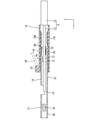
- FIGS. 9 to 11 show a state in which the slide portion 18 is temporarily locked to the wire connecting portion 19.
- the locking protrusion 23 of the electric wire connection portion 19 is fitted inside the temporary locking portion 31 of the slide portion 18.
- the front half portion of the slide portion 18 is approximately two thirds long from the rear end portion in the front-rear direction of the electric wire connection portion 19. It is externally fitted up to the size.
- the rear end portion of the first clamping portion 14 is located in front of the front end portions of the first pressing portions 16A and 16B.
- the rear end portion of the second clamping portion 15 is located in front of the front end portions of the second pressing portions 17A and 17B.
- the first clamping part 14 and the second clamping part 15 are exposed from the opening on the rear side of the slide part 18.
- the core wire 13 is inserted into the space between the first clamping part 14 and the second clamping part 15.
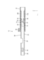
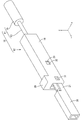
- FIGS. 13 to 15 show a state in which the slide portion 18 is fully locked to the wire connecting portion 19.
- the locking projection 23 of the wire connecting portion 19 is fitted inside the main locking portion 32 of the slide portion 18.
- the slide portion 18 In a state where the slide portion 18 is held at the main locking position with respect to the wire connection portion 19, the slide portion 18 completely covers the wire connection portion 19 in the front-rear direction.
- the front end portion of the slide portion 18 is located in front of the front end portion of the electric wire connection portion 19, and the rear end portion of the slide portion 18 is located rearward of the rear end portion of the electric wire connection portion 19.
- the first pressing portions 16A and 16B are in contact with the upper surface of the first sandwiching portion 14 (the surface opposite to the first contact surface 24) from above. Thereby, the 1st clamping part 14 is bent below, and is contact
- the second pressing portions 17A and 17B are in contact with the lower surface of the second sandwiching portion 15 (the surface opposite to the second contact surface 27) from below. Thereby, the 2nd clamping part 15 bends upwards and is contact
- the first holding part 14 and the first pressing parts 16A and 16B are pressed from above, and the second holding part 15 is pressed by the second pressing parts 17A and 17B from below so that the first holding part 14 and the first pressing part 14
- the core wire 13 disposed between the two sandwiching portions 15 is sandwiched between the first sandwiching portion 14 and the second sandwiching portion 15. Thereby, the electric wire 11 and the female terminal 12 are electrically connected.
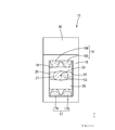
- the core wire 13 is deformed into an oval shape that is flat in the vertical direction when viewed from behind by being pinched from the vertical direction (see FIG. 15).
- the core wire 13 is sandwiched between the first protrusion 25 of the first holding part 14 and the second protrusion 28 of the second holding part 15 provided so as to be shifted in the front-rear direction. It is bent in a crank shape. Thereby, the core wire 13 is firmly held between the first sandwiching portion 14 and the second sandwiching portion 15.
- the core wire 13 When the first contact surface 24 of the first clamping unit 14 is pressed against the core wire 13, the core wire 13 is fitted into the first serration 26 formed on the first contact surface 24. Thereby, the oxide film formed on the surface of the core wire 13 is peeled off and the metal surface is exposed. When the exposed metal surface and the first contact surface 24 come into contact with each other, the electrical resistance between the first sandwiching portion 14 and the core wire 13 can be reduced.
- the core wire 13 is fitted into the second serration 29 formed on the second contact surface 27 by pressing the second contact surface 27 of the second sandwiching portion 15 against the core wire 13. Thereby, the oxide film formed on the surface of the core wire 13 is peeled off and the metal surface is exposed. When the exposed metal surface and the second contact surface 27 come into contact with each other, the electrical resistance between the second sandwiching portion 15 and the core wire 13 can be reduced.
- the axis 33 of the core wire 13 is located between the two first pressing portions 16A and 16B arranged in the left-right direction, and two second lines arranged in the left-right direction. It is located between the pressing portions 17A and 17B.
- connection process of the female terminal 12 and the electric wire 11 An example of the connection process of the female terminal 12 and the electric wire 11 which concerns on this embodiment is demonstrated.
- connection process of the female terminal 12 and the electric wire 11 it is not limited to the following description.
- the slide part 18 is externally fitted to the electric wire connection part 19 of the female terminal 12 from behind.
- the rear end portion of the electric wire connecting portion 19 of the female terminal 12 is inserted into the opening on the front side of the slide portion 18, and the slide portion 18 is moved forward.
- the locking projections 23 of the wire connection part 19 come into contact with the opening edge on the front side of the slide part 18 from the front, the left and right side walls of the wire connection part 19 are elastically deformed inward in the left-right direction.
- the slide portion 18 is further moved forward, the locking projections 23 are fitted into the temporary locking portions 31, and the left and right side walls of the wire connecting portion 19 are restored and deformed.
- the locking projection 23 comes into contact with the hole edge portion of the temporary locking portion 31 from the front or the rear, so that the slide portion 18 is held at the temporary locking position with respect to the wire connection portion 19 (see FIG. 9 to 11).
- the insulation coating 35 is peeled off at the end of the electric wire 11 to expose the core wire 13.
- the exposed core wire 13 is inserted from the opening on the rear side of the slide portion 18. Further, the core wire 13 is inserted forward so that the front end portion of the core wire 13 is positioned inside the extending portion 21. By visually recognizing the extended portion 21 from above, it can be confirmed that the front end portion of the core wire 13 is located inside the extended portion 21 (see FIG. 12).
- the jig 34 is brought into contact with the jig abutting portion 30 from the rear and pressed from the rear to move the slide portion 18 forward. Then, the left and right side walls of the slide portion 18 ride on the locking projections 23 of the wire connection portion 19. As a result, the left and right side walls of the wire connecting portion 19 are elastically deformed inward in the left-right direction.
- the first pressing portions 16A and 16B come into contact with the upper surface of the first clamping portion 14 from above, and the second pressing portions 17A and 17B are lowered on the lower surface of the second clamping portion 15. Abut.
- the first pressing parts 16A and 16B press the first clamping part 14 from above to below, and the second pressing parts 17A and 17B push the second clamping part 15 from below. Press upward.
- the first sandwiching portion 14 is deformed downward and the second sandwiching portion 15 is deformed upward, whereby the core wire 13 is sandwiched between the first sandwiching portion 14 and the second sandwiching portion 15.
- the female terminal 12 is a female terminal 12 connected to the terminal of the electric wire 11, has a base 22, extends from the base 22 along the extending direction, and holds the electric wire 11.
- the wire holding part 19 having the holding part 14 and the second holding part 15 is movable along the extending direction, and the first holding part 14 is brought into contact with the first holding part 14 and the second holding part 15.
- the first pressing portions 16A and 16B that press the second clamping portion 15 toward the electric wire 11, and the slide portion 18 including the second pressing portions 17A and 17B, and the first pressing portions 16A and 16B and the second pressing portion 16 are provided.
- the pressing parts 17A and 17B are formed so as to protrude toward the first clamping part 14 and the second clamping part 15, and are formed side by side in a direction intersecting the extending direction.
- the female terminal 12 is connected to the end of the electric wire 11.
- tip of 1st press part 16A, 16B and 2nd press part 17A, 17B contacts the 1st clamping part 14 and the 2nd clamping part 15, respectively.
- the first pressing portions 16A and 16B and the second pressing portions 17A and 17B are dispersed at a plurality of locations where the first pressing portions 16A and 17B are in contact with the first clamping portion 14 and the second clamping portion 15.
- the contact area between the second pressing portions 17A and 17B and the first and second clamping portions 14 and 15 can be reduced.
- the slide part 18 can be easily moved forward, the efficiency of the connection work between the female terminal 12 and the electric wire 11 can be improved.
- the first pressing portions 16A and 16B and the second pressing portions 17A and 17B are formed extending along the front-rear direction.
- the slide part 18 can be moved smoothly.
- the efficiency of the connection work of the female terminal 12 and the electric wire 11 can be improved further.
- the axial center 33 of the electric wire 11 is located between the two adjacent first pressing portions 16A and 16B. Moreover, the axial center 33 of the electric wire 11 is located between two adjacent 2nd press part 17A, 17B. Thereby, the first clamping part 14 pressed by the two first pressing parts 16A and 16B and the second clamping part 15 pressed by the two second pressing parts 17A and 17B are outside the electric wire 11. Since it deforms along the shape, the deformation amount of the first sandwiching portion 14 and the second sandwiching portion 15 can be suppressed. As a result, the pressing force required to deform the first clamping part 14 and the second clamping part 15 is reduced, so that the slide part 18 can be easily moved forward. As a result, the efficiency of the connection work between the female terminal 12 and the electric wire 11 can be further improved.
- the female terminal 12 has the first holding portion 14 and the second holding portion 15.
- the present invention is not limited to this, and the number of holding portions may be one, or three or more. But you can.
- first pressing portions 16A and 16B and the second pressing portions 17A and 17B are formed side by side in the left-right direction, but the present invention is not limited to this. Two or more pressing portions may be formed side by side in the left-right direction.
- a terminal may be a male terminal and may be a splice terminal.
- the electric wire 11 may be a bare electric wire.
- the core wire 13 may be a stranded wire.
- the pressing portions may be formed in a discrete manner along the extending direction.
- the base portion 22 has a rectangular tube shape, but is not limited thereto, and the base portion 22 may have a cylindrical shape, or may have a polygonal cylindrical shape such as a triangular cylindrical shape.
- the slide part 18 material may also be a cylindrical shape, and may be a polygonal cylindrical shape such as a triangular cylindrical shape.
- the first pressing portions 16A and 16B and the second pressing portions 17A and 17B are appropriately selected from arbitrary shapes such as a triangular shape, a semicircular shape, and an oval shape as viewed from the rear. be able to.
- SYMBOLS 10 Electric wire with a terminal 11: Electric wire 12: Female terminal 14: 1st clamping part 15: 2nd clamping part 16A, 16B: 1st press part 17A, 17B: 2nd press part 18: Slide part 19: Electric wire connection part 22 :base
Landscapes
- Connections Effected By Soldering, Adhesion, Or Permanent Deformation (AREA)
- Insulated Conductors (AREA)
- Connections By Means Of Piercing Elements, Nuts, Or Screws (AREA)
Priority Applications (2)
| Application Number | Priority Date | Filing Date | Title |
|---|---|---|---|
| CN201980011714.3A CN111684661B (zh) | 2018-02-15 | 2019-02-05 | 端子及带端子电线 |
| US16/968,928 US11165172B2 (en) | 2018-02-15 | 2019-02-05 | Terminal and wire with terminal |
Applications Claiming Priority (2)
| Application Number | Priority Date | Filing Date | Title |
|---|---|---|---|
| JP2018-025418 | 2018-02-15 | ||
| JP2018025418A JP6939625B2 (ja) | 2018-02-15 | 2018-02-15 | 端子、及び端子付き電線 |
Publications (1)
| Publication Number | Publication Date |
|---|---|
| WO2019159746A1 true WO2019159746A1 (ja) | 2019-08-22 |
Family
ID=67619825
Family Applications (1)
| Application Number | Title | Priority Date | Filing Date |
|---|---|---|---|
| PCT/JP2019/003954 Ceased WO2019159746A1 (ja) | 2018-02-15 | 2019-02-05 | 端子、及び端子付き電線 |
Country Status (4)
| Country | Link |
|---|---|
| US (1) | US11165172B2 (enExample) |
| JP (1) | JP6939625B2 (enExample) |
| CN (1) | CN111684661B (enExample) |
| WO (1) | WO2019159746A1 (enExample) |
Cited By (3)
| Publication number | Priority date | Publication date | Assignee | Title |
|---|---|---|---|---|
| WO2020196478A1 (ja) * | 2019-03-28 | 2020-10-01 | 株式会社オートネットワーク技術研究所 | ジョイントコネクタ |
| WO2020196480A1 (ja) * | 2019-03-28 | 2020-10-01 | 株式会社オートネットワーク技術研究所 | ジョイントコネクタ |
| JP2021034307A (ja) * | 2019-08-28 | 2021-03-01 | 株式会社オートネットワーク技術研究所 | 端子、および端子付き電線 |
Families Citing this family (6)
| Publication number | Priority date | Publication date | Assignee | Title |
|---|---|---|---|---|
| JP7121913B2 (ja) * | 2019-05-08 | 2022-08-19 | 株式会社オートネットワーク技術研究所 | 端子、および端子付き電線 |
| JP7133513B2 (ja) * | 2019-06-12 | 2022-09-08 | 株式会社オートネットワーク技術研究所 | 端子、および端子付き電線 |
| JP7431091B2 (ja) * | 2020-04-03 | 2024-02-14 | 矢崎総業株式会社 | 接続端子 |
| JP2021190286A (ja) * | 2020-05-29 | 2021-12-13 | 株式会社オートネットワーク技術研究所 | 端子、および端子付き電線 |
| JP7478057B2 (ja) | 2020-07-30 | 2024-05-02 | タイコエレクトロニクスジャパン合同会社 | 電気端子 |
| JP7638770B2 (ja) * | 2021-04-07 | 2025-03-04 | TE Connectivity Japan合同会社 | 端子 |
Citations (5)
| Publication number | Priority date | Publication date | Assignee | Title |
|---|---|---|---|---|
| JPS6228370U (enExample) * | 1985-08-02 | 1987-02-20 | ||
| US20020119710A1 (en) * | 2001-02-27 | 2002-08-29 | Fci Usa, Inc. | Electrical connector having frame and slidable members |
| WO2013137415A1 (ja) * | 2012-03-16 | 2013-09-19 | 日本発條株式会社 | コネクタ |
| JP2015056209A (ja) * | 2013-09-10 | 2015-03-23 | ヒロセ電機株式会社 | 電気コネクタ用端子及び電気コネクタ |
| JP2017174595A (ja) * | 2016-03-23 | 2017-09-28 | 矢崎総業株式会社 | 端子接続構造 |
Family Cites Families (13)
| Publication number | Priority date | Publication date | Assignee | Title |
|---|---|---|---|---|
| US3243757A (en) * | 1964-01-20 | 1966-03-29 | Amp Inc | Electrical connections |
| JPS6228370A (ja) | 1985-07-22 | 1987-02-06 | コニカ株式会社 | シ−ト状物収納体 |
| JPH0997633A (ja) * | 1995-09-28 | 1997-04-08 | Japan Aviation Electron Ind Ltd | コンタクト |
| CN2653721Y (zh) * | 2003-06-02 | 2004-11-03 | 江门市汇聪电器厂有限公司 | 一种导线连接装置 |
| JP2005050736A (ja) | 2003-07-30 | 2005-02-24 | Furukawa Electric Co Ltd:The | アルミ電線への端子圧着構造及び端子付アルミ電線の製造方法 |
| EP2472675B1 (en) | 2003-07-30 | 2020-09-30 | The Furukawa Electric Co., Ltd. | Terminal crimping structure and terminal crimping method onto aluminum electric-wire |
| JP2006049211A (ja) * | 2004-08-06 | 2006-02-16 | Three M Innovative Properties Co | 同軸ケーブル接地構造並びにコネクタ及びその結線方法 |
| US7086897B2 (en) * | 2004-11-18 | 2006-08-08 | John Mezzalingua Associates, Inc. | Compression connector and method of use |
| JP2009176617A (ja) * | 2008-01-25 | 2009-08-06 | Sumitomo Wiring Syst Ltd | 端子および端子の接続構造 |
| JP5274693B1 (ja) * | 2012-06-15 | 2013-08-28 | 昌範 木本 | 電力ケーブル用接続器 |
| JP6185295B2 (ja) | 2013-06-13 | 2017-08-23 | Candart株式会社 | 刺繍機 |
| JP2015156285A (ja) * | 2014-02-20 | 2015-08-27 | 住友電装株式会社 | 接続端子及びワイヤーハーネス |
| JP6086940B2 (ja) * | 2015-06-03 | 2017-03-01 | 株式会社木村電気工業 | 電線接続装置 |
-
2018
- 2018-02-15 JP JP2018025418A patent/JP6939625B2/ja active Active
-
2019
- 2019-02-05 US US16/968,928 patent/US11165172B2/en active Active
- 2019-02-05 CN CN201980011714.3A patent/CN111684661B/zh active Active
- 2019-02-05 WO PCT/JP2019/003954 patent/WO2019159746A1/ja not_active Ceased
Patent Citations (5)
| Publication number | Priority date | Publication date | Assignee | Title |
|---|---|---|---|---|
| JPS6228370U (enExample) * | 1985-08-02 | 1987-02-20 | ||
| US20020119710A1 (en) * | 2001-02-27 | 2002-08-29 | Fci Usa, Inc. | Electrical connector having frame and slidable members |
| WO2013137415A1 (ja) * | 2012-03-16 | 2013-09-19 | 日本発條株式会社 | コネクタ |
| JP2015056209A (ja) * | 2013-09-10 | 2015-03-23 | ヒロセ電機株式会社 | 電気コネクタ用端子及び電気コネクタ |
| JP2017174595A (ja) * | 2016-03-23 | 2017-09-28 | 矢崎総業株式会社 | 端子接続構造 |
Cited By (6)
| Publication number | Priority date | Publication date | Assignee | Title |
|---|---|---|---|---|
| WO2020196478A1 (ja) * | 2019-03-28 | 2020-10-01 | 株式会社オートネットワーク技術研究所 | ジョイントコネクタ |
| WO2020196480A1 (ja) * | 2019-03-28 | 2020-10-01 | 株式会社オートネットワーク技術研究所 | ジョイントコネクタ |
| US11942737B2 (en) | 2019-03-28 | 2024-03-26 | Autonetworks Technologies, Ltd. | Joint connector |
| US12062874B2 (en) | 2019-03-28 | 2024-08-13 | Autonetworks Technologies, Ltd. | Joint connector |
| JP2021034307A (ja) * | 2019-08-28 | 2021-03-01 | 株式会社オートネットワーク技術研究所 | 端子、および端子付き電線 |
| JP7216895B2 (ja) | 2019-08-28 | 2023-02-02 | 株式会社オートネットワーク技術研究所 | 端子、および端子付き電線 |
Also Published As
| Publication number | Publication date |
|---|---|
| US11165172B2 (en) | 2021-11-02 |
| JP6939625B2 (ja) | 2021-09-22 |
| JP2019145213A (ja) | 2019-08-29 |
| CN111684661B (zh) | 2022-08-23 |
| CN111684661A (zh) | 2020-09-18 |
| US20210050677A1 (en) | 2021-02-18 |
Similar Documents
| Publication | Publication Date | Title |
|---|---|---|
| WO2019159746A1 (ja) | 端子、及び端子付き電線 | |
| JP6954170B2 (ja) | 端子 | |
| US11394136B2 (en) | Terminal | |
| JP6652583B2 (ja) | 端子付き電線 | |
| JP2020107615A (ja) | ケーブル組立体 | |
| EP2159880A1 (en) | A terminal fitting and a wire connected with a terminal fitting | |
| JP7183914B2 (ja) | 端子および端子付き電線 | |
| WO2020196480A1 (ja) | ジョイントコネクタ | |
| US20220224024A1 (en) | Terminal and wire with terminal | |
| US20220239019A1 (en) | Terminal and terminal wire assembly | |
| CN115244788B (zh) | 端子以及带端子的电线 | |
| KR102338051B1 (ko) | 동축 커넥터 및 동축 케이블을 구비한 동축 커넥터 | |
| US12074401B2 (en) | Terminal and wire with terminal | |
| JP7255449B2 (ja) | ジョイントコネクタ | |
| CN114270629A (zh) | 端子及带端子电线 | |
| US12266897B2 (en) | Terminal and wire with terminal | |
| JP2012119216A (ja) | 圧着端子及び端子付電線 | |
| US20220376419A1 (en) | Terminal and electric cable including terminal | |
| JP5151936B2 (ja) | 端子金具及びその製造方法 | |
| US20220209434A1 (en) | Terminal and wire with terminal | |
| JP2007048696A (ja) | ケーブル接続用コンタクト及び当該コンタクトを用いたケーブル接続方法 | |
| JP2001251723A (ja) | 圧接金型 |
Legal Events
| Date | Code | Title | Description |
|---|---|---|---|
| 121 | Ep: the epo has been informed by wipo that ep was designated in this application |
Ref document number: 19755253 Country of ref document: EP Kind code of ref document: A1 |
|
| NENP | Non-entry into the national phase |
Ref country code: DE |
|
| 122 | Ep: pct application non-entry in european phase |
Ref document number: 19755253 Country of ref document: EP Kind code of ref document: A1 |