WO2019159746A1 - Terminal and electrical wire with terminal - Google Patents
Terminal and electrical wire with terminal Download PDFInfo
- Publication number
- WO2019159746A1 WO2019159746A1 PCT/JP2019/003954 JP2019003954W WO2019159746A1 WO 2019159746 A1 WO2019159746 A1 WO 2019159746A1 JP 2019003954 W JP2019003954 W JP 2019003954W WO 2019159746 A1 WO2019159746 A1 WO 2019159746A1
- Authority
- WO
- WIPO (PCT)
- Prior art keywords
- electric wire
- terminal
- slide
- pressing
- wire
- Prior art date
Links
Images


Classifications
-
- H—ELECTRICITY
- H01—ELECTRIC ELEMENTS
- H01R—ELECTRICALLY-CONDUCTIVE CONNECTIONS; STRUCTURAL ASSOCIATIONS OF A PLURALITY OF MUTUALLY-INSULATED ELECTRICAL CONNECTING ELEMENTS; COUPLING DEVICES; CURRENT COLLECTORS
- H01R4/00—Electrically-conductive connections between two or more conductive members in direct contact, i.e. touching one another; Means for effecting or maintaining such contact; Electrically-conductive connections having two or more spaced connecting locations for conductors and using contact members penetrating insulation
- H01R4/10—Electrically-conductive connections between two or more conductive members in direct contact, i.e. touching one another; Means for effecting or maintaining such contact; Electrically-conductive connections having two or more spaced connecting locations for conductors and using contact members penetrating insulation effected solely by twisting, wrapping, bending, crimping, or other permanent deformation
- H01R4/18—Electrically-conductive connections between two or more conductive members in direct contact, i.e. touching one another; Means for effecting or maintaining such contact; Electrically-conductive connections having two or more spaced connecting locations for conductors and using contact members penetrating insulation effected solely by twisting, wrapping, bending, crimping, or other permanent deformation by crimping
-
- H—ELECTRICITY
- H01—ELECTRIC ELEMENTS
- H01R—ELECTRICALLY-CONDUCTIVE CONNECTIONS; STRUCTURAL ASSOCIATIONS OF A PLURALITY OF MUTUALLY-INSULATED ELECTRICAL CONNECTING ELEMENTS; COUPLING DEVICES; CURRENT COLLECTORS
- H01R4/00—Electrically-conductive connections between two or more conductive members in direct contact, i.e. touching one another; Means for effecting or maintaining such contact; Electrically-conductive connections having two or more spaced connecting locations for conductors and using contact members penetrating insulation
- H01R4/28—Clamped connections, spring connections
- H01R4/50—Clamped connections, spring connections utilising a cam, wedge, cone or ball also combined with a screw
- H01R4/5083—Clamped connections, spring connections utilising a cam, wedge, cone or ball also combined with a screw using a wedge
-
- H—ELECTRICITY
- H01—ELECTRIC ELEMENTS
- H01B—CABLES; CONDUCTORS; INSULATORS; SELECTION OF MATERIALS FOR THEIR CONDUCTIVE, INSULATING OR DIELECTRIC PROPERTIES
- H01B7/00—Insulated conductors or cables characterised by their form
-
- H—ELECTRICITY
- H01—ELECTRIC ELEMENTS
- H01R—ELECTRICALLY-CONDUCTIVE CONNECTIONS; STRUCTURAL ASSOCIATIONS OF A PLURALITY OF MUTUALLY-INSULATED ELECTRICAL CONNECTING ELEMENTS; COUPLING DEVICES; CURRENT COLLECTORS
- H01R13/00—Details of coupling devices of the kinds covered by groups H01R12/70 or H01R24/00 - H01R33/00
- H01R13/02—Contact members
- H01R13/26—Pin or blade contacts for sliding co-operation on one side only
-
- H—ELECTRICITY
- H01—ELECTRIC ELEMENTS
- H01R—ELECTRICALLY-CONDUCTIVE CONNECTIONS; STRUCTURAL ASSOCIATIONS OF A PLURALITY OF MUTUALLY-INSULATED ELECTRICAL CONNECTING ELEMENTS; COUPLING DEVICES; CURRENT COLLECTORS
- H01R4/00—Electrically-conductive connections between two or more conductive members in direct contact, i.e. touching one another; Means for effecting or maintaining such contact; Electrically-conductive connections having two or more spaced connecting locations for conductors and using contact members penetrating insulation
- H01R4/24—Connections using contact members penetrating or cutting insulation or cable strands
- H01R4/2491—Connections using contact members penetrating or cutting insulation or cable strands the contact members penetrating the insulation being actuated by conductive cams or wedges
-
- H—ELECTRICITY
- H01—ELECTRIC ELEMENTS
- H01R—ELECTRICALLY-CONDUCTIVE CONNECTIONS; STRUCTURAL ASSOCIATIONS OF A PLURALITY OF MUTUALLY-INSULATED ELECTRICAL CONNECTING ELEMENTS; COUPLING DEVICES; CURRENT COLLECTORS
- H01R4/00—Electrically-conductive connections between two or more conductive members in direct contact, i.e. touching one another; Means for effecting or maintaining such contact; Electrically-conductive connections having two or more spaced connecting locations for conductors and using contact members penetrating insulation
- H01R4/28—Clamped connections, spring connections
- H01R4/48—Clamped connections, spring connections utilising a spring, clip, or other resilient member
Definitions
- the technology disclosed in this specification relates to a terminal and an electric wire with a terminal.
- a terminal connected to a core wire exposed from the end of an electric wire is known.
- This terminal includes a crimping portion that crimps the core wire exposed from the end of the electric wire from the outside.
- a terminal having a predetermined shape is formed by pressing a metal plate material.
- a terminal is mounted on the mounting part of the lower mold located on the lower side of the pair of molds that can move in the vertical direction.
- the core wire exposed from the end of the electric wire is placed over the crimping portion of the terminal.
- one or both of the pair of molds are moved in a direction approaching each other, and the crimping part is sandwiched between the crimping part of the upper mold and the mounting part of the lower mold, thereby fixing the crimping part to the core wire of the electric wire.
- Crimp to. the terminal is connected to the end of the electric wire (see Patent Document 1).
- a terminal having a pair of clamping parts for clamping the electric wire is conceivable.
- a core wire is disposed between the pair of holding portions of the terminal, and a slide member having a pressing portion that presses the pair of holding portions toward the core wire is slid from the direction in which the electric wire is led out from the terminal.
- the pressing part pressed the pair of holding parts toward the core wire, and the pair of holding parts was expected to connect the terminal and the electric wire by holding the core wire.
- the technology disclosed in the present specification has been completed based on the above situation, and aims to improve the efficiency of the connection work between the terminal and the electric wire.
- the technology disclosed in the present specification is a terminal connected to a terminal of an electric wire, and has a base, an electric wire having a holding portion that extends from the base along the extending direction and holds the electric wire.
- a connecting portion and a plurality of pressing portions that are movable with respect to the electric wire connecting portion along the extending direction and press the holding portion toward the electric wire by contacting the holding portion.
- the plurality of pressing portions are formed so as to protrude toward the clamping portion, and are formed side by side in a direction intersecting the extending direction. .
- the technology disclosed in the present specification is a terminal-attached electric wire that includes the terminal and an electric wire connected to the terminal.
- the tips of the plurality of pressing parts are in contact with the clamping parts, respectively.
- the part which a press part contacts with a clamping part is disperse
- the slide part can be easily moved in the extending direction, so that the efficiency of the connection work between the terminal and the electric wire can be improved.
- the pressing portion is formed to extend along the extending direction.
- the slide portion can be moved more smoothly than in the case where the plurality of pressing portions are discretely formed along the extending direction. Thereby, the efficiency of the connection work of a terminal and an electric wire can be improved further.
- the electric wire is arranged between adjacent pressing portions among the plurality of pressing portions.
- the sandwiching portion pressed by the plurality of pressing portions is deformed along the outer shape of the electric wire, the deformation amount of the sandwiching portion can be suppressed. As a result, the pressing force necessary for deforming the clamping portion is reduced, so that the slide portion can be easily moved in the extending direction. As a result, the efficiency of the connection work between the terminal and the electric wire can be further improved.
- the efficiency of the connection work between the terminal and the electric wire can be improved.
- the exploded perspective view which shows the electric wire and female terminal based on Embodiment 1 The perspective view which shows the connection cylinder part, extension part, and electric wire connection part of a female terminal Side view of female terminal, showing connection tube, extension, and wire connection Rear view of female terminal, showing connection tube, extension, and wire connection Sectional drawing which shows the connection cylinder part, extension part, and electric wire connection part of a female terminal Partially enlarged sectional view showing the wire connection part Perspective view showing the slide part Rear view showing slide part
- Perspective view showing electric wire with terminal Sectional view showing the electric wire with terminal XV-XV sectional view in FIG.
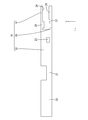
- the electric wire with terminal 10 includes an electric wire 11 and a female terminal 12 (an example of a terminal) connected to the electric wire 11.
- symbol may be attached
- the electric wire 11 includes a core wire 13 and an insulating coating 35 made of an insulating synthetic resin that covers the outer periphery of the core wire 13.
- a metal which comprises the core wire 13 it can select suitably from arbitrary metals as needed, such as copper, a copper alloy, aluminum, an aluminum alloy.
- the core wire 13 according to the present embodiment is made of copper or a copper alloy.
- the core wire 13 may be a stranded wire formed by twisting a plurality of metal strands, or may be a single core wire made of one rod-shaped metal material.
- the core wire 13 which concerns on this embodiment consists of a single core wire.
- the female terminal 12 has an electric wire connection having a first holding part 14 (an example of a holding part) and a second holding part 15 (an example of a holding part) that hold the core wire 13 of the electric wire 11.
- a slide part 18 provided with
- the female terminal 12 is made of a conductive metal material.
- a metal which comprises a terminal it can select suitably from arbitrary metals as needed, such as copper, copper alloy, aluminum, aluminum alloy.
- the terminal according to the present embodiment is made of copper or a copper alloy.
- the female terminal 12 can be formed by a known method such as cutting, casting, or pressing.
- the female terminal 12 has a connecting cylinder portion 20 into which a male terminal (not shown) is inserted.
- the connecting tube portion 20 has a rectangular tube shape extending in the front-rear direction.
- the connecting cylinder part 20 is open forward and backward.
- An elastic connection piece (not shown) that elastically contacts the male terminal is disposed inside the connection cylinder portion 20. The elastic connection piece elastically contacts the male terminal, whereby the male terminal and the female terminal 12 are electrically connected.
- the rear end portion of the connecting tube portion 20 is connected to an extending portion 21 extending rearward.
- the wire connecting portion 19 is connected to the rear end portion of the extending portion 21.
- the electric wire connecting portion 19 includes a base portion 22 and a first holding portion 14 and a second holding portion 15 that extend rearward (an example of the extending direction) from the rear end portion of the base portion 22.
- the extended portion 21 is formed to open upward. Thereby, the core wire 13 arranged inside the extending portion 21 can be viewed from above.
- the base 22 has a rectangular tube shape extending in the front-rear direction.
- the base 22 opens forward and backward.
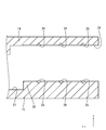
- the first clamping portion 14 extends rearward (an example of the extending direction) from the rear end portion of the upper wall of the base portion 22.
- the 1st clamping part 14 has comprised the plate shape elongated in the front-back direction.
- the 1st clamping part 14 is formed so that bending deformation is possible about the plate
- the lower surface of the first clamping unit 14 is a first contact surface 24 that contacts the core wire 13.
- a first protrusion 25 that protrudes downward from the first contact surface 24 is formed at a position near the front end of the first sandwiching portion 14.
- a plurality of first serrations 26 that extend in the left-right direction and are arranged at intervals in the front-rear direction in the first contact surface 24 of the first holding portion 14 at a position behind the first protrusion 25 are V-shaped grooves. (See FIG. 6).
- the second sandwiching portion 15 extends backward (an example of the extending direction) from the rear end portion of the lower wall of the base portion 22.
- the 2nd clamping part 15 has comprised the plate shape elongated in the front-back direction.
- the 2nd clamping part 15 is formed so that bending deformation is possible about a plate
- the upper surface of the second clamping unit 15 is a second contact surface 27 that contacts the core wire 13.
- a second protrusion 28 protruding upward from the second contact surface 27 is provided on the second contact surface 27 of the second sandwiching portion 15 at a position rearward of the rear end portion of the first protrusion of the first sandwiching portion 14. Is formed.
- On the upper surface of the second protrusion 28, a plurality of second serrations 29 extending in the left-right direction and arranged at intervals in the front-rear direction are formed in a V-shaped groove shape (see FIG. 6).
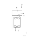
- the slide part 18 has a rectangular tube shape elongated in the front-rear direction, and is open in the front-rear direction.
- the opening on the front side of the slide portion 18 is formed to be the same as or slightly larger than the outer shape of the wire connection portion 19, and the wire connection portion 19 can be inserted.
- the slide portion 18 can be formed of any material such as metal, synthetic resin, ceramic, or the like as necessary.
- a metal which comprises the slide part 18 arbitrary metals can be suitably selected as needed, such as copper, copper alloy, aluminum, aluminum alloy, and stainless steel.
- the slide portion 18 is formed of a metal, it can be formed by any method as necessary, such as cutting, casting, or pressing.
- a jig contact portion 30 protruding upward is provided at the front end portion of the upper wall of the slide portion 18.
- the slide portion 18 slides forward.
- a temporary locking portion 31 to be held is provided.
- the temporary locking portion 31 is formed as a through-hole penetrating the left side wall and the right side wall of the slide portion 18.
- the size of the hole edge of the temporary locking portion 31 is the same as or slightly larger than that of the locking projection 23, and the locking projection 23 can be fitted into the temporary locking portion 31.
- the left side wall and the right side wall of the slide part 18 are elastically locked to the locking protrusions 23 behind the temporary locking part 31, respectively.
- a main locking portion 32 that is held at the locking position is provided.
- the main locking portion 32 is formed as a through-hole penetrating the left side wall and the right side wall of the slide portion 18.
- the size of the hole edge of the main locking part 32 is the same as or slightly larger than that of the locking protrusion 23, and the locking protrusion 23 can be fitted into the main locking part 32.
- the lower surface of the upper wall of the slide portion 18 has a plurality of (two in the present embodiment) first pressing portions 16 ⁇ / b> A protruding downward at a position behind the center position in the front-rear direction.
- 16B is formed extending in the front-rear direction.
- the rear end portions of the first pressing portions 16A and 16B extend to a position slightly ahead of the rear end portion of the slide portion 18 material.
- the two first pressing portions 16A and 16B are arranged at intervals in the left-right direction.
- the projecting dimensions of the two first pressing portions 16A and 16B from the upper wall of the slide portion 18 are the same.
- a plurality of (two in this embodiment) second pressing portions 17 ⁇ / b> A and 17 ⁇ / b> B project in the front-rear direction and protrude rearward from the center position in the front-rear direction. Is formed.
- the rear end portions of the second pressing portions 17A and 17B extend to a position slightly ahead of the rear end portion of the slide portion 18 material.
- the two second pressing portions 17A and 17B are arranged at intervals in the left-right direction. The projecting dimensions of the two second pressing portions 17A and 17B from the upper wall of the slide portion 18 are the same.
- the lower ends of the first pressing portions 16A and 16B have a quadrangular shape with ridges rounded when viewed from the rear.
- the width dimension of the left-right direction in the lower end part of 1st press part 16A, 16B is smaller than the width dimension of the left-right direction in the upper end part of 1st press part 16A, 16B seeing from back.
- the contact area between the first pressing portions 16A and 16B and the first clamping portion 14 is smaller than that when the ridge portion is not rounded.
- the upper end portions of the second pressing portions 17A and 17B have a quadrangular shape with rounded ridges when viewed from the rear. Thereby, the width dimension of the left-right direction in the upper end part of 2nd press part 17A, 17B is smaller than the width dimension of the left-right direction in the lower end part of 2nd press part 17A, 17B seeing from back. As a result, the contact area between the second pressing portions 17A and 17B and the second sandwiching portion 15 is smaller than when the ridge portion is not rounded.
- FIGS. 9 to 11 show a state in which the slide portion 18 is temporarily locked to the wire connecting portion 19.
- the locking protrusion 23 of the electric wire connection portion 19 is fitted inside the temporary locking portion 31 of the slide portion 18.
- the front half portion of the slide portion 18 is approximately two thirds long from the rear end portion in the front-rear direction of the electric wire connection portion 19. It is externally fitted up to the size.
- the rear end portion of the first clamping portion 14 is located in front of the front end portions of the first pressing portions 16A and 16B.
- the rear end portion of the second clamping portion 15 is located in front of the front end portions of the second pressing portions 17A and 17B.
- the first clamping part 14 and the second clamping part 15 are exposed from the opening on the rear side of the slide part 18.
- the core wire 13 is inserted into the space between the first clamping part 14 and the second clamping part 15.
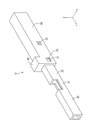
- FIGS. 13 to 15 show a state in which the slide portion 18 is fully locked to the wire connecting portion 19.
- the locking projection 23 of the wire connecting portion 19 is fitted inside the main locking portion 32 of the slide portion 18.
- the slide portion 18 In a state where the slide portion 18 is held at the main locking position with respect to the wire connection portion 19, the slide portion 18 completely covers the wire connection portion 19 in the front-rear direction.
- the front end portion of the slide portion 18 is located in front of the front end portion of the electric wire connection portion 19, and the rear end portion of the slide portion 18 is located rearward of the rear end portion of the electric wire connection portion 19.
- the first pressing portions 16A and 16B are in contact with the upper surface of the first sandwiching portion 14 (the surface opposite to the first contact surface 24) from above. Thereby, the 1st clamping part 14 is bent below, and is contact
- the second pressing portions 17A and 17B are in contact with the lower surface of the second sandwiching portion 15 (the surface opposite to the second contact surface 27) from below. Thereby, the 2nd clamping part 15 bends upwards and is contact
- the first holding part 14 and the first pressing parts 16A and 16B are pressed from above, and the second holding part 15 is pressed by the second pressing parts 17A and 17B from below so that the first holding part 14 and the first pressing part 14
- the core wire 13 disposed between the two sandwiching portions 15 is sandwiched between the first sandwiching portion 14 and the second sandwiching portion 15. Thereby, the electric wire 11 and the female terminal 12 are electrically connected.
- the core wire 13 is deformed into an oval shape that is flat in the vertical direction when viewed from behind by being pinched from the vertical direction (see FIG. 15).
- the core wire 13 is sandwiched between the first protrusion 25 of the first holding part 14 and the second protrusion 28 of the second holding part 15 provided so as to be shifted in the front-rear direction. It is bent in a crank shape. Thereby, the core wire 13 is firmly held between the first sandwiching portion 14 and the second sandwiching portion 15.
- the core wire 13 When the first contact surface 24 of the first clamping unit 14 is pressed against the core wire 13, the core wire 13 is fitted into the first serration 26 formed on the first contact surface 24. Thereby, the oxide film formed on the surface of the core wire 13 is peeled off and the metal surface is exposed. When the exposed metal surface and the first contact surface 24 come into contact with each other, the electrical resistance between the first sandwiching portion 14 and the core wire 13 can be reduced.
- the core wire 13 is fitted into the second serration 29 formed on the second contact surface 27 by pressing the second contact surface 27 of the second sandwiching portion 15 against the core wire 13. Thereby, the oxide film formed on the surface of the core wire 13 is peeled off and the metal surface is exposed. When the exposed metal surface and the second contact surface 27 come into contact with each other, the electrical resistance between the second sandwiching portion 15 and the core wire 13 can be reduced.
- the axis 33 of the core wire 13 is located between the two first pressing portions 16A and 16B arranged in the left-right direction, and two second lines arranged in the left-right direction. It is located between the pressing portions 17A and 17B.
- connection process of the female terminal 12 and the electric wire 11 An example of the connection process of the female terminal 12 and the electric wire 11 which concerns on this embodiment is demonstrated.
- connection process of the female terminal 12 and the electric wire 11 it is not limited to the following description.
- the slide part 18 is externally fitted to the electric wire connection part 19 of the female terminal 12 from behind.
- the rear end portion of the electric wire connecting portion 19 of the female terminal 12 is inserted into the opening on the front side of the slide portion 18, and the slide portion 18 is moved forward.
- the locking projections 23 of the wire connection part 19 come into contact with the opening edge on the front side of the slide part 18 from the front, the left and right side walls of the wire connection part 19 are elastically deformed inward in the left-right direction.
- the slide portion 18 is further moved forward, the locking projections 23 are fitted into the temporary locking portions 31, and the left and right side walls of the wire connecting portion 19 are restored and deformed.
- the locking projection 23 comes into contact with the hole edge portion of the temporary locking portion 31 from the front or the rear, so that the slide portion 18 is held at the temporary locking position with respect to the wire connection portion 19 (see FIG. 9 to 11).
- the insulation coating 35 is peeled off at the end of the electric wire 11 to expose the core wire 13.
- the exposed core wire 13 is inserted from the opening on the rear side of the slide portion 18. Further, the core wire 13 is inserted forward so that the front end portion of the core wire 13 is positioned inside the extending portion 21. By visually recognizing the extended portion 21 from above, it can be confirmed that the front end portion of the core wire 13 is located inside the extended portion 21 (see FIG. 12).
- the jig 34 is brought into contact with the jig abutting portion 30 from the rear and pressed from the rear to move the slide portion 18 forward. Then, the left and right side walls of the slide portion 18 ride on the locking projections 23 of the wire connection portion 19. As a result, the left and right side walls of the wire connecting portion 19 are elastically deformed inward in the left-right direction.
- the first pressing portions 16A and 16B come into contact with the upper surface of the first clamping portion 14 from above, and the second pressing portions 17A and 17B are lowered on the lower surface of the second clamping portion 15. Abut.
- the first pressing parts 16A and 16B press the first clamping part 14 from above to below, and the second pressing parts 17A and 17B push the second clamping part 15 from below. Press upward.
- the first sandwiching portion 14 is deformed downward and the second sandwiching portion 15 is deformed upward, whereby the core wire 13 is sandwiched between the first sandwiching portion 14 and the second sandwiching portion 15.
- the female terminal 12 is a female terminal 12 connected to the terminal of the electric wire 11, has a base 22, extends from the base 22 along the extending direction, and holds the electric wire 11.
- the wire holding part 19 having the holding part 14 and the second holding part 15 is movable along the extending direction, and the first holding part 14 is brought into contact with the first holding part 14 and the second holding part 15.
- the first pressing portions 16A and 16B that press the second clamping portion 15 toward the electric wire 11, and the slide portion 18 including the second pressing portions 17A and 17B, and the first pressing portions 16A and 16B and the second pressing portion 16 are provided.
- the pressing parts 17A and 17B are formed so as to protrude toward the first clamping part 14 and the second clamping part 15, and are formed side by side in a direction intersecting the extending direction.
- the female terminal 12 is connected to the end of the electric wire 11.
- tip of 1st press part 16A, 16B and 2nd press part 17A, 17B contacts the 1st clamping part 14 and the 2nd clamping part 15, respectively.
- the first pressing portions 16A and 16B and the second pressing portions 17A and 17B are dispersed at a plurality of locations where the first pressing portions 16A and 17B are in contact with the first clamping portion 14 and the second clamping portion 15.
- the contact area between the second pressing portions 17A and 17B and the first and second clamping portions 14 and 15 can be reduced.
- the slide part 18 can be easily moved forward, the efficiency of the connection work between the female terminal 12 and the electric wire 11 can be improved.
- the first pressing portions 16A and 16B and the second pressing portions 17A and 17B are formed extending along the front-rear direction.
- the slide part 18 can be moved smoothly.
- the efficiency of the connection work of the female terminal 12 and the electric wire 11 can be improved further.
- the axial center 33 of the electric wire 11 is located between the two adjacent first pressing portions 16A and 16B. Moreover, the axial center 33 of the electric wire 11 is located between two adjacent 2nd press part 17A, 17B. Thereby, the first clamping part 14 pressed by the two first pressing parts 16A and 16B and the second clamping part 15 pressed by the two second pressing parts 17A and 17B are outside the electric wire 11. Since it deforms along the shape, the deformation amount of the first sandwiching portion 14 and the second sandwiching portion 15 can be suppressed. As a result, the pressing force required to deform the first clamping part 14 and the second clamping part 15 is reduced, so that the slide part 18 can be easily moved forward. As a result, the efficiency of the connection work between the female terminal 12 and the electric wire 11 can be further improved.
- the female terminal 12 has the first holding portion 14 and the second holding portion 15.
- the present invention is not limited to this, and the number of holding portions may be one, or three or more. But you can.
- first pressing portions 16A and 16B and the second pressing portions 17A and 17B are formed side by side in the left-right direction, but the present invention is not limited to this. Two or more pressing portions may be formed side by side in the left-right direction.
- a terminal may be a male terminal and may be a splice terminal.
- the electric wire 11 may be a bare electric wire.
- the core wire 13 may be a stranded wire.
- the pressing portions may be formed in a discrete manner along the extending direction.
- the base portion 22 has a rectangular tube shape, but is not limited thereto, and the base portion 22 may have a cylindrical shape, or may have a polygonal cylindrical shape such as a triangular cylindrical shape.
- the slide part 18 material may also be a cylindrical shape, and may be a polygonal cylindrical shape such as a triangular cylindrical shape.
- the first pressing portions 16A and 16B and the second pressing portions 17A and 17B are appropriately selected from arbitrary shapes such as a triangular shape, a semicircular shape, and an oval shape as viewed from the rear. be able to.
- SYMBOLS 10 Electric wire with a terminal 11: Electric wire 12: Female terminal 14: 1st clamping part 15: 2nd clamping part 16A, 16B: 1st press part 17A, 17B: 2nd press part 18: Slide part 19: Electric wire connection part 22 :base
Abstract
A female terminal 12 is connected to a terminal of an electrical wire 11, and is provided with: an electrical wire connection 19 having a base 22, and first and second pinching parts 14, 15 that pinch the electrical wire 11 and that extend from the base 22 in the extending direction; and a slide part 18 that is slidable along the extending direction and that is provided with first pressing parts 16A, 16B and second pressing parts 17A, 17B for pressing the first pinching part 14 and the second pinching part 15 toward the electrical wire 11 by abutting against the first pinching part 14 and the second pinching part 15. The first pressing parts 16A, 16B and the second pressing parts 17A, 17B are formed so as to project toward the first pinching part 14 and the second pinching part 15, and are formed so as to be aligned with gaps in a direction intersecting the extending direction.
Description
本明細書に開示された技術は、端子、及び端子付き電線に関する。
The technology disclosed in this specification relates to a terminal and an electric wire with a terminal.
従来より、電線の端末から露出する芯線に接続される端子が知られている。この端子は、電線の端末から露出する芯線に外側から圧着する圧着部を備える。
Conventionally, a terminal connected to a core wire exposed from the end of an electric wire is known. This terminal includes a crimping portion that crimps the core wire exposed from the end of the electric wire from the outside.
上記の端子を電線に圧着するには、例えば以下のようにする。まず、金属板材をプレス加工することにより所定の形状の端子を成形する。続いて、上下方向に相対移動可能な一対の金型のうち下側に位置する下型の載置部に、端子を載置する。続いて、電線の端末から露出された芯線を、端子の圧着部に重ねて載置する。その後、一対の金型の一方又は双方を互いに接近する方向に移動させ、上型の圧着部と、下型の載置部との間で圧着部を挟み付けることにより、圧着部を電線の芯線に圧着する。以上により、電線の端末に端子が接続される(特許文献1参照)。
To crimp the above terminal to the wire, for example: First, a terminal having a predetermined shape is formed by pressing a metal plate material. Then, a terminal is mounted on the mounting part of the lower mold located on the lower side of the pair of molds that can move in the vertical direction. Subsequently, the core wire exposed from the end of the electric wire is placed over the crimping portion of the terminal. Thereafter, one or both of the pair of molds are moved in a direction approaching each other, and the crimping part is sandwiched between the crimping part of the upper mold and the mounting part of the lower mold, thereby fixing the crimping part to the core wire of the electric wire. Crimp to. Thus, the terminal is connected to the end of the electric wire (see Patent Document 1).
しかしながら上記の技術によれば、電線の芯線に端子の圧着部を圧着するための金型が必要なので、設備投資が必要となり、製造コストが上昇するという問題がある。
However, according to the above technique, since a die for crimping the crimping portion of the terminal to the core wire of the electric wire is necessary, there is a problem that equipment investment is required and the manufacturing cost increases.
上記の問題を解決するために、電線を挟持する一対の挟持部を備えた端子が考えられる。この端子の一対の挟持部の間に芯線を配し、端子から電線が導出される方向から、一対の挟持部を芯線に向かって押圧する押圧部を有するスライド部材をスライドさせる。これにより、押圧部は一対の挟持部を芯線に向かって押圧し、一対の挟持部は芯線を挟持することにより、端子と電線とが接続されることが期待された。
In order to solve the above-described problem, a terminal having a pair of clamping parts for clamping the electric wire is conceivable. A core wire is disposed between the pair of holding portions of the terminal, and a slide member having a pressing portion that presses the pair of holding portions toward the core wire is slid from the direction in which the electric wire is led out from the terminal. Thereby, the pressing part pressed the pair of holding parts toward the core wire, and the pair of holding parts was expected to connect the terminal and the electric wire by holding the core wire.
しかしながら、端子の挟持部と芯線との間の接触抵抗を小さくするためには、かなりの押圧力が必要となる。このため、スライド部材の押圧部により、挟持部を芯線に向かって十分に大きな力で押圧する必要がある。この結果、スライド部材をスライドさせることが困難となり、端子と電線との接続作業の効率が低下することが懸念された。
However, in order to reduce the contact resistance between the terminal clamping part and the core wire, a considerable pressing force is required. For this reason, it is necessary to press the clamping part with a sufficiently large force toward the core wire by the pressing part of the slide member. As a result, it is difficult to slide the slide member, and there is a concern that the efficiency of the connection work between the terminal and the electric wire is reduced.
本明細書に開示された技術は上記のような事情に基づいて完成されたものであって、端子と電線との接続作業の効率を向上させることを目的とする。
The technology disclosed in the present specification has been completed based on the above situation, and aims to improve the efficiency of the connection work between the terminal and the electric wire.
本明細書に開示された技術は、電線の端末に接続される端子であって、基部を有し、前記基部から延出方向に沿って延出されると共に前記電線を挟持する挟持部を有する電線接続部と、前記延出方向に沿って前記電線接続部に対して移動可能なスライド部であって、前記挟持部と当接することにより前記挟持部を前記電線に向かって押圧する複数の押圧部を備えた前記スライド部と、を備え、前記複数の押圧部は前記挟持部に向かって突出して形成されていると共に、前記延出方向と交差する方向に間隔を空けて並んで形成されている。
The technology disclosed in the present specification is a terminal connected to a terminal of an electric wire, and has a base, an electric wire having a holding portion that extends from the base along the extending direction and holds the electric wire. A connecting portion and a plurality of pressing portions that are movable with respect to the electric wire connecting portion along the extending direction and press the holding portion toward the electric wire by contacting the holding portion. The plurality of pressing portions are formed so as to protrude toward the clamping portion, and are formed side by side in a direction intersecting the extending direction. .
また、本明細書に開示された技術は、上記の端子と、前記端子に接続された電線と、を備えた端子付き電線である。
Further, the technology disclosed in the present specification is a terminal-attached electric wire that includes the terminal and an electric wire connected to the terminal.
上記の構成によれば、複数の押圧部の先端が、それぞれ、挟持部と接するようになっている。これにより、押圧部が挟持部と接触する部分が複数個所に分散するので、押圧部と、挟持部との接触面積を小さくすることができる。この結果、スライド部を延出方向に移動させやすくすることができるので、端子と電線との接続作業の効率を向上させることができる。
According to the above configuration, the tips of the plurality of pressing parts are in contact with the clamping parts, respectively. Thereby, since the part which a press part contacts with a clamping part is disperse | distributed in multiple places, the contact area of a pressing part and a clamping part can be made small. As a result, the slide part can be easily moved in the extending direction, so that the efficiency of the connection work between the terminal and the electric wire can be improved.
本明細書に開示された技術の実施態様としては以下の態様が好ましい。
The following embodiments are preferred as embodiments of the technology disclosed in this specification.
前記押圧部は前記延出方向に沿って延びて形成されていることが好ましい。
It is preferable that the pressing portion is formed to extend along the extending direction.
上記の構成によれば、複数の押圧部が延出方向に沿って離散的に形成されている場合に比べて、スライド部をスムーズに移動させることができる。これにより、端子と電線との接続作業の効率を一層向上させることができる。
According to the above configuration, the slide portion can be moved more smoothly than in the case where the plurality of pressing portions are discretely formed along the extending direction. Thereby, the efficiency of the connection work of a terminal and an electric wire can be improved further.
前記複数の押圧部のうち隣り合う押圧部の間に前記電線が配されていることが好ましい。
It is preferable that the electric wire is arranged between adjacent pressing portions among the plurality of pressing portions.
上記の構成によれば、複数の押圧部に押圧された挟持部は、電線の外形状に沿って変形するので、挟持部の変形量を抑制することができる。この結果、挟持部を変形させるために必要な押圧力が減少するので、スライド部を延出方向に容易に移動させることができる。この結果、端子と電線との接続作業の効率を更に向上させることができる。
According to the above configuration, since the sandwiching portion pressed by the plurality of pressing portions is deformed along the outer shape of the electric wire, the deformation amount of the sandwiching portion can be suppressed. As a result, the pressing force necessary for deforming the clamping portion is reduced, so that the slide portion can be easily moved in the extending direction. As a result, the efficiency of the connection work between the terminal and the electric wire can be further improved.
本明細書に開示された技術によれば、端子と電線との接続作業の効率を向上させることができる。
According to the technique disclosed in this specification, the efficiency of the connection work between the terminal and the electric wire can be improved.
<実施形態1>
本明細書に開示された技術の実施形態1を、図1から図15を参照しつつ説明する。本実施形態に係る端子付き電線10は、電線11と、電線11に接続された雌端子12(端子の一例)と、を備える。以下の説明では、Z方向を上方とし、Y方向を前方とし、X方向を左方として説明する。また、複数の同一部材については、一部の部材にのみ符号を付し、他の部材については符号を省略する場合がある。 <Embodiment 1>
Embodiment 1 of the technique disclosed in this specification will be described with reference to FIGS. 1 to 15. The electric wire withterminal 10 according to the present embodiment includes an electric wire 11 and a female terminal 12 (an example of a terminal) connected to the electric wire 11. In the following description, it is assumed that the Z direction is upward, the Y direction is front, and the X direction is left. Moreover, about several same members, a code | symbol may be attached | subjected only to some members, and a code | symbol may be abbreviate | omitted about another member.
本明細書に開示された技術の実施形態1を、図1から図15を参照しつつ説明する。本実施形態に係る端子付き電線10は、電線11と、電線11に接続された雌端子12(端子の一例)と、を備える。以下の説明では、Z方向を上方とし、Y方向を前方とし、X方向を左方として説明する。また、複数の同一部材については、一部の部材にのみ符号を付し、他の部材については符号を省略する場合がある。 <Embodiment 1>
Embodiment 1 of the technique disclosed in this specification will be described with reference to FIGS. 1 to 15. The electric wire with
・電線11
図1に示すように、電線11は、芯線13と、芯線13の外周を覆う絶縁性の合成樹脂からなる絶縁被覆35と、を備える。芯線13を構成する金属としては、銅、銅合金、アルミニウム、アルミニウム合金等、必要に応じて任意の金属から適宜に選択することができる。本実施形態に係る芯線13は銅、又は銅合金からなる。芯線13は、複数の金属素線を撚り合わせてなる撚り線でもよく、1つの棒状の金属材料からなる単芯線でもよい。本実施形態に係る芯線13は単芯線からなる。 ・ Wire 11
As shown in FIG. 1, theelectric wire 11 includes a core wire 13 and an insulating coating 35 made of an insulating synthetic resin that covers the outer periphery of the core wire 13. As a metal which comprises the core wire 13, it can select suitably from arbitrary metals as needed, such as copper, a copper alloy, aluminum, an aluminum alloy. The core wire 13 according to the present embodiment is made of copper or a copper alloy. The core wire 13 may be a stranded wire formed by twisting a plurality of metal strands, or may be a single core wire made of one rod-shaped metal material. The core wire 13 which concerns on this embodiment consists of a single core wire.
図1に示すように、電線11は、芯線13と、芯線13の外周を覆う絶縁性の合成樹脂からなる絶縁被覆35と、を備える。芯線13を構成する金属としては、銅、銅合金、アルミニウム、アルミニウム合金等、必要に応じて任意の金属から適宜に選択することができる。本実施形態に係る芯線13は銅、又は銅合金からなる。芯線13は、複数の金属素線を撚り合わせてなる撚り線でもよく、1つの棒状の金属材料からなる単芯線でもよい。本実施形態に係る芯線13は単芯線からなる。 ・ Wire 11
As shown in FIG. 1, the
・雌端子12
図2~図3に示すように、雌端子12は、電線11の芯線13を挟持する第1挟持部14(挟持部の一例)及び第2挟持部15(挟持部の一例)を有する電線接続部19と、第1挟持部14及び第2挟持部15を芯線13に向かって押圧する第1押圧部16A,16B(押圧部の一例)及び第2押圧部17A,17B(押圧部の一例)を備えたスライド部18と、を備える。 -Female terminal 12
As shown in FIGS. 2 to 3, thefemale terminal 12 has an electric wire connection having a first holding part 14 (an example of a holding part) and a second holding part 15 (an example of a holding part) that hold the core wire 13 of the electric wire 11. The first pressing portions 16A and 16B (an example of a pressing portion) and the second pressing portions 17A and 17B (an example of a pressing portion) that press the portion 19, the first clamping portion 14 and the second clamping portion 15 toward the core wire 13. And a slide part 18 provided with
図2~図3に示すように、雌端子12は、電線11の芯線13を挟持する第1挟持部14(挟持部の一例)及び第2挟持部15(挟持部の一例)を有する電線接続部19と、第1挟持部14及び第2挟持部15を芯線13に向かって押圧する第1押圧部16A,16B(押圧部の一例)及び第2押圧部17A,17B(押圧部の一例)を備えたスライド部18と、を備える。 -
As shown in FIGS. 2 to 3, the
雌端子12は導電性の金属材料からなる。端子を構成する金属としては、銅、銅合金、アルミニウム、アルミニウム合金等、必要に応じて任意の金属から適宜に選択することができる。本実施形態に係る端子は銅、又は銅合金からなる。雌端子12は、切削加工、鋳造、プレス加工等、公知の手法により形成することができる。
The female terminal 12 is made of a conductive metal material. As a metal which comprises a terminal, it can select suitably from arbitrary metals as needed, such as copper, copper alloy, aluminum, aluminum alloy. The terminal according to the present embodiment is made of copper or a copper alloy. The female terminal 12 can be formed by a known method such as cutting, casting, or pressing.
雌端子12は、図示しない雄端子が挿入される接続筒部20を有する。接続筒部20は前後方向に延びる角筒状をなしている。接続筒部20は前方及び後方に開口している。接続筒部20の内部には、雄端子と弾性的に接触する弾性接続片(図示せず)が配されている。この弾性接続片が雄端子に弾性的に接触することにより、雄端子と雌端子12とが電気的に接続されるようになっている。
The female terminal 12 has a connecting cylinder portion 20 into which a male terminal (not shown) is inserted. The connecting tube portion 20 has a rectangular tube shape extending in the front-rear direction. The connecting cylinder part 20 is open forward and backward. An elastic connection piece (not shown) that elastically contacts the male terminal is disposed inside the connection cylinder portion 20. The elastic connection piece elastically contacts the male terminal, whereby the male terminal and the female terminal 12 are electrically connected.
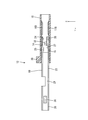
接続筒部20の後端部には、後方に延びる延設部21が連なっている。この延設部21の後端部には、電線接続部19が連なっている。電線接続部19は、基部22と、基部22の後端部から後方(延出方向の一例)に延出された第1挟持部14及び第2挟持部15と、を備える。
The rear end portion of the connecting tube portion 20 is connected to an extending portion 21 extending rearward. The wire connecting portion 19 is connected to the rear end portion of the extending portion 21. The electric wire connecting portion 19 includes a base portion 22 and a first holding portion 14 and a second holding portion 15 that extend rearward (an example of the extending direction) from the rear end portion of the base portion 22.
延設部21は上方に開口して形成されている。これにより、延設部21の内部に配された芯線13を上方から視認可能になっている。
The extended portion 21 is formed to open upward. Thereby, the core wire 13 arranged inside the extending portion 21 can be viewed from above.
基部22は、前後方向に延びる角筒状をなしている。基部22は前方及び後方に開口している。基部22の左側壁、及び右側壁には、それぞれ、左右方向に突出する係止突起23が設けられている(図4参照)。
The base 22 has a rectangular tube shape extending in the front-rear direction. The base 22 opens forward and backward. On the left side wall and the right side wall of the base 22, there are provided locking projections 23 that protrude in the left-right direction (see FIG. 4).
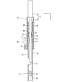
図5に示すように、基部22の上壁の後端部からは、第1挟持部14が後方(延出方向の一例)に延出されている。第1挟持部14は前後方向に細長く延びる板状をなしている。第1挟持部14は、板厚方向(上下方向)について撓み変形可能に形成されている。第1挟持部14の下面は、芯線13と接触する第1接触面24とされる。第1挟持部14の前端部寄りの位置には、第1接触面24から下方に突出する第1突起25が形成されている。第1挟持部14の第1接触面24のうち、第1突起25よりも後方の位置には、左右方向に延びると共に前後方向に間隔を空けて並ぶ複数の第1セレーション26が、V字溝状に形成されている(図6参照)。
As shown in FIG. 5, the first clamping portion 14 extends rearward (an example of the extending direction) from the rear end portion of the upper wall of the base portion 22. The 1st clamping part 14 has comprised the plate shape elongated in the front-back direction. The 1st clamping part 14 is formed so that bending deformation is possible about the plate | board thickness direction (up-down direction). The lower surface of the first clamping unit 14 is a first contact surface 24 that contacts the core wire 13. A first protrusion 25 that protrudes downward from the first contact surface 24 is formed at a position near the front end of the first sandwiching portion 14. A plurality of first serrations 26 that extend in the left-right direction and are arranged at intervals in the front-rear direction in the first contact surface 24 of the first holding portion 14 at a position behind the first protrusion 25 are V-shaped grooves. (See FIG. 6).
図5に示すように、基部22の下壁の後端部からは、第2挟持部15が後方(延出方向の一例)に延出されている。第2挟持部15は前後方向に細長く延びる板状をなしている。第2挟持部15は、板厚方向(上下方向)について撓み変形可能に形成されている。第2挟持部15の上面は、芯線13と接触する第2接触面27とされる。第2挟持部15の第2接触面27には、第1挟持部14の第1突部の後端部よりも後方の位置に、第2接触面27から上方に突出する第2突起28が形成されている。第2突起28の上面には、左右方向に延びると共に前後方向に間隔を空けて並ぶ複数の第2セレーション29が、V字溝状に形成されている(図6参照)。
As shown in FIG. 5, the second sandwiching portion 15 extends backward (an example of the extending direction) from the rear end portion of the lower wall of the base portion 22. The 2nd clamping part 15 has comprised the plate shape elongated in the front-back direction. The 2nd clamping part 15 is formed so that bending deformation is possible about a plate | board thickness direction (up-down direction). The upper surface of the second clamping unit 15 is a second contact surface 27 that contacts the core wire 13. A second protrusion 28 protruding upward from the second contact surface 27 is provided on the second contact surface 27 of the second sandwiching portion 15 at a position rearward of the rear end portion of the first protrusion of the first sandwiching portion 14. Is formed. On the upper surface of the second protrusion 28, a plurality of second serrations 29 extending in the left-right direction and arranged at intervals in the front-rear direction are formed in a V-shaped groove shape (see FIG. 6).
・スライド部18
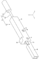
図7に示すように、スライド部18は前後方向に細長い角筒状をなしており、前後に開口している。スライド部18の前側の開口は、電線接続部19の外形状と同じか、やや大きく形成されており、電線接続部19が挿入可能になっている。スライド部18は、金属、合成樹脂、セラミック等、必要に応じて任意の材料により形成することができる。スライド部18を構成する金属としては、銅、銅合金、アルミニウム、アルミニウム合金、ステンレス鋼等、必要に応じて任意の金属を適宜に選択することができる。スライド部18を金属で形成する場合には、切削加工、鋳造、プレス加工等、必要に応じて任意の手法により形成することができる。 ・Slide part 18
As shown in FIG. 7, theslide part 18 has a rectangular tube shape elongated in the front-rear direction, and is open in the front-rear direction. The opening on the front side of the slide portion 18 is formed to be the same as or slightly larger than the outer shape of the wire connection portion 19, and the wire connection portion 19 can be inserted. The slide portion 18 can be formed of any material such as metal, synthetic resin, ceramic, or the like as necessary. As a metal which comprises the slide part 18, arbitrary metals can be suitably selected as needed, such as copper, copper alloy, aluminum, aluminum alloy, and stainless steel. When the slide portion 18 is formed of a metal, it can be formed by any method as necessary, such as cutting, casting, or pressing.
図7に示すように、スライド部18は前後方向に細長い角筒状をなしており、前後に開口している。スライド部18の前側の開口は、電線接続部19の外形状と同じか、やや大きく形成されており、電線接続部19が挿入可能になっている。スライド部18は、金属、合成樹脂、セラミック等、必要に応じて任意の材料により形成することができる。スライド部18を構成する金属としては、銅、銅合金、アルミニウム、アルミニウム合金、ステンレス鋼等、必要に応じて任意の金属を適宜に選択することができる。スライド部18を金属で形成する場合には、切削加工、鋳造、プレス加工等、必要に応じて任意の手法により形成することができる。 ・
As shown in FIG. 7, the
スライド部18の上壁の前端部には、上方に突出する治具当接部30が設けられている。この治具当接部30が治具34により後方から押圧されることにより、スライド部18が前方にスライドするようになっている。
A jig contact portion 30 protruding upward is provided at the front end portion of the upper wall of the slide portion 18. When the jig contact portion 30 is pressed from behind by the jig 34, the slide portion 18 slides forward.
スライド部18の左側壁、及び右側壁の前端部寄りの位置には、それぞれ、係止突起23と弾性的に係止して、スライド部18を電線接続部19に対して仮係止位置に保持する仮係止部31が設けられている。仮係止部31は、スライド部18の左側壁、及び右側壁を貫通する貫通孔として形成されている。仮係止部31の孔縁の大きさは、係止突起23と同じか、やや大きく形成されており、係止突起23が仮係止部31内に嵌入可能になっている。
At the positions near the front end of the left side wall and the right side wall of the slide part 18, the slide part 18 is elastically locked with the locking projection 23, and the slide part 18 is in the temporary locking position with respect to the electric wire connection part 19. A temporary locking portion 31 to be held is provided. The temporary locking portion 31 is formed as a through-hole penetrating the left side wall and the right side wall of the slide portion 18. The size of the hole edge of the temporary locking portion 31 is the same as or slightly larger than that of the locking projection 23, and the locking projection 23 can be fitted into the temporary locking portion 31.
スライド部18の左側壁、及び右側壁には、仮係止部31よりも後方に、それぞれ、係止突起23と弾性的に係止して、スライド部18を電線接続部19に対して本係止位置に保持する本係止部32が設けられている。本係止部32は、スライド部18の左側壁、及び右側壁を貫通する貫通孔として形成されている。本係止部32の孔縁の大きさは、係止突起23と同じか、やや大きく形成されており、係止突起23が本係止部32内に嵌入可能になっている。
The left side wall and the right side wall of the slide part 18 are elastically locked to the locking protrusions 23 behind the temporary locking part 31, respectively. A main locking portion 32 that is held at the locking position is provided. The main locking portion 32 is formed as a through-hole penetrating the left side wall and the right side wall of the slide portion 18. The size of the hole edge of the main locking part 32 is the same as or slightly larger than that of the locking protrusion 23, and the locking protrusion 23 can be fitted into the main locking part 32.
図8に示すように、スライド部18の上壁の下面には、前後方向の中央位置よりも後方の位置に、下方に突出する複数(本実施形態では2個)の第1押圧部16A,16Bが前後方向に延びて形成されている。第1押圧部16A,16Bの後端部は、スライド部18材の後端部よりもやや前方の位置にまで延びている。2個の第1押圧部16A,16Bは、左右方向に間隔を空けて並んでいる。2個の第1押圧部16A,16Bの、スライド部18の上壁からの突出寸法は、同じに形成されている。
As shown in FIG. 8, the lower surface of the upper wall of the slide portion 18 has a plurality of (two in the present embodiment) first pressing portions 16 </ b> A protruding downward at a position behind the center position in the front-rear direction. 16B is formed extending in the front-rear direction. The rear end portions of the first pressing portions 16A and 16B extend to a position slightly ahead of the rear end portion of the slide portion 18 material. The two first pressing portions 16A and 16B are arranged at intervals in the left-right direction. The projecting dimensions of the two first pressing portions 16A and 16B from the upper wall of the slide portion 18 are the same.
スライド部18の下壁の上面には、前後方向の中央位置よりも後方の位置に、上方に突出する複数(本実施形態では2個)の第2押圧部17A,17Bが前後方向に延びて形成されている。第2押圧部17A,17Bの後端部は、スライド部18材の後端部よりもやや前方の位置にまで延びている。2個の第2押圧部17A,17Bは、左右方向に間隔を空けて並んでいる。2個の第2押圧部17A,17Bの、スライド部18の上壁からの突出寸法は、同じに形成されている。
On the upper surface of the lower wall of the slide portion 18, a plurality of (two in this embodiment) second pressing portions 17 </ b> A and 17 </ b> B project in the front-rear direction and protrude rearward from the center position in the front-rear direction. Is formed. The rear end portions of the second pressing portions 17A and 17B extend to a position slightly ahead of the rear end portion of the slide portion 18 material. The two second pressing portions 17A and 17B are arranged at intervals in the left-right direction. The projecting dimensions of the two second pressing portions 17A and 17B from the upper wall of the slide portion 18 are the same.
第1押圧部16A,16Bの下端部は、後方から見て、稜部が丸められた四角形状をなしている。これにより、後方から見て、第1押圧部16A,16Bの上端部における左右方向の幅寸法よりも、第1押圧部16A,16Bの下端部における左右方向の幅寸法は小さくなっている。この結果、第1押圧部16A,16Bと第1挟持部14との接触面積は、稜部が丸められていない場合に比べて小さくなっている。
The lower ends of the first pressing portions 16A and 16B have a quadrangular shape with ridges rounded when viewed from the rear. Thereby, the width dimension of the left-right direction in the lower end part of 1st press part 16A, 16B is smaller than the width dimension of the left-right direction in the upper end part of 1st press part 16A, 16B seeing from back. As a result, the contact area between the first pressing portions 16A and 16B and the first clamping portion 14 is smaller than that when the ridge portion is not rounded.
第2押圧部17A,17Bの上端部は、後方から見て、稜部が丸められた四角形状をなしている。これにより、後方から見て、第2押圧部17A,17Bの下端部における左右方向の幅寸法よりも、第2押圧部17A,17Bの上端部における左右方向の幅寸法は小さくなっている。この結果、第2押圧部17A,17Bと第2挟持部15との接触面積は、稜部が丸められていない場合に比べて小さくなっている。
The upper end portions of the second pressing portions 17A and 17B have a quadrangular shape with rounded ridges when viewed from the rear. Thereby, the width dimension of the left-right direction in the upper end part of 2nd press part 17A, 17B is smaller than the width dimension of the left-right direction in the lower end part of 2nd press part 17A, 17B seeing from back. As a result, the contact area between the second pressing portions 17A and 17B and the second sandwiching portion 15 is smaller than when the ridge portion is not rounded.
・仮係止状態
図9~図11に、スライド部18が電線接続部19に仮係止された状態を示す。電線接続部19の係止突起23は、スライド部18の仮係止部31の内部に内嵌されている。スライド部18が電線接続部19に対して仮係止位置に保持された状態では、スライド部18の前半部分は、電線接続部19のうち前後方向について後端部から概ね三分の二の長さ寸法まで、外嵌されている。 Temporary Locking State FIGS. 9 to 11 show a state in which theslide portion 18 is temporarily locked to the wire connecting portion 19. The locking protrusion 23 of the electric wire connection portion 19 is fitted inside the temporary locking portion 31 of the slide portion 18. In a state where the slide portion 18 is held at the temporary locking position with respect to the electric wire connection portion 19, the front half portion of the slide portion 18 is approximately two thirds long from the rear end portion in the front-rear direction of the electric wire connection portion 19. It is externally fitted up to the size.
図9~図11に、スライド部18が電線接続部19に仮係止された状態を示す。電線接続部19の係止突起23は、スライド部18の仮係止部31の内部に内嵌されている。スライド部18が電線接続部19に対して仮係止位置に保持された状態では、スライド部18の前半部分は、電線接続部19のうち前後方向について後端部から概ね三分の二の長さ寸法まで、外嵌されている。 Temporary Locking State FIGS. 9 to 11 show a state in which the
図10に示すように、仮係止状態においては、第1挟持部14の後端部は第1押圧部16A,16Bの前端部よりも前方に位置している。第2挟持部15の後端部は第2押圧部17A,17Bの前端部よりも前方に位置している。換言すると、仮係止状態においては、第1挟持部14と第1押圧部16A,16Bは当接しておらず、第2挟持部15と第2押圧部17A,17Bも当接していない。
As shown in FIG. 10, in the temporarily locked state, the rear end portion of the first clamping portion 14 is located in front of the front end portions of the first pressing portions 16A and 16B. The rear end portion of the second clamping portion 15 is located in front of the front end portions of the second pressing portions 17A and 17B. In other words, in the temporarily locked state, the first clamping part 14 and the first pressing parts 16A and 16B are not in contact, and the second clamping part 15 and the second pressing parts 17A and 17B are not in contact.
図11に示すように、スライド部18の後側の開口からは、第1挟持部14と、第2挟持部15が露出している。第1挟持部14と第2挟持部15との間の空間内に、芯線13が挿入されるようになっている。
As shown in FIG. 11, the first clamping part 14 and the second clamping part 15 are exposed from the opening on the rear side of the slide part 18. The core wire 13 is inserted into the space between the first clamping part 14 and the second clamping part 15.
・本係止状態
図13~図15に、スライド部18が電線接続部19に本係止された状態を示す。電線接続部19の係止突起23は、スライド部18の本係止部32の内部に内嵌されている。スライド部18が電線接続部19に対して本係止位置に保持された状態では、スライド部18は、電線接続部19を前後方向について完全に覆っている。スライド部18の前端部は電線接続部19の前端部よりも前方に位置しており、スライド部18の後端部は電線接続部19の後端部よりも後方に位置している。 -Mainly Locked State FIGS. 13 to 15 show a state in which theslide portion 18 is fully locked to the wire connecting portion 19. The locking projection 23 of the wire connecting portion 19 is fitted inside the main locking portion 32 of the slide portion 18. In a state where the slide portion 18 is held at the main locking position with respect to the wire connection portion 19, the slide portion 18 completely covers the wire connection portion 19 in the front-rear direction. The front end portion of the slide portion 18 is located in front of the front end portion of the electric wire connection portion 19, and the rear end portion of the slide portion 18 is located rearward of the rear end portion of the electric wire connection portion 19.
図13~図15に、スライド部18が電線接続部19に本係止された状態を示す。電線接続部19の係止突起23は、スライド部18の本係止部32の内部に内嵌されている。スライド部18が電線接続部19に対して本係止位置に保持された状態では、スライド部18は、電線接続部19を前後方向について完全に覆っている。スライド部18の前端部は電線接続部19の前端部よりも前方に位置しており、スライド部18の後端部は電線接続部19の後端部よりも後方に位置している。 -Mainly Locked State FIGS. 13 to 15 show a state in which the
図14に示すように、第1押圧部16A,16Bは、第1挟持部14の上面(第1接触面24と反対側の面)に、上方から当接している。これにより、第1挟持部14は下方に屈曲し、芯線13に対して上方から当接している。
As shown in FIG. 14, the first pressing portions 16A and 16B are in contact with the upper surface of the first sandwiching portion 14 (the surface opposite to the first contact surface 24) from above. Thereby, the 1st clamping part 14 is bent below, and is contact | abutting with respect to the core wire 13 from upper direction.
第2押圧部17A,17Bは、第2挟持部15の下面(第2接触面27と反対側の面)に、下方から当接している。これにより、第2挟持部15は上方に屈曲し、芯線13に対して下方から当接している。
The second pressing portions 17A and 17B are in contact with the lower surface of the second sandwiching portion 15 (the surface opposite to the second contact surface 27) from below. Thereby, the 2nd clamping part 15 bends upwards and is contact | abutting with respect to the core wire 13 from the downward direction.
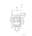
第1挟持部14が上方から第1押圧部16A,16Bに押圧されると共に、第2挟持部15が下方から第2押圧部17A,17Bに押圧されることにより、第1挟持部14と第2挟持部15との間に配された芯線13は、第1挟持部14と第2挟持部15によって挟持されている。これにより、電線11と雌端子12とが電気的に接続される。芯線13は、上下方向から挟圧されることにより、後方から見て、上下方向に扁平な長円形状に変形している(図15参照)。
The first holding part 14 and the first pressing parts 16A and 16B are pressed from above, and the second holding part 15 is pressed by the second pressing parts 17A and 17B from below so that the first holding part 14 and the first pressing part 14 The core wire 13 disposed between the two sandwiching portions 15 is sandwiched between the first sandwiching portion 14 and the second sandwiching portion 15. Thereby, the electric wire 11 and the female terminal 12 are electrically connected. The core wire 13 is deformed into an oval shape that is flat in the vertical direction when viewed from behind by being pinched from the vertical direction (see FIG. 15).
図14に示すように、芯線13は、前後方向にずれて設けられた第1挟持部14の第1突起25と、第2挟持部15の第2突起28との間に挟まれることにより、クランク状に屈曲されている。これにより、芯線13は、第1挟持部14と第2挟持部15との間に強固に保持されるようになっている。
As shown in FIG. 14, the core wire 13 is sandwiched between the first protrusion 25 of the first holding part 14 and the second protrusion 28 of the second holding part 15 provided so as to be shifted in the front-rear direction. It is bent in a crank shape. Thereby, the core wire 13 is firmly held between the first sandwiching portion 14 and the second sandwiching portion 15.
第1挟持部14の第1接触面24が芯線13に押圧されることにより、第1接触面24に形成された第1セレーション26の内部に芯線13が嵌入する。これにより、芯線13の表面に形成された酸化被膜が剥がされて金属表面が露出する。露出した金属表面と第1接触面24とが接触することにより、第1挟持部14と芯線13との電気抵抗を小さくすることができるようになっている。
When the first contact surface 24 of the first clamping unit 14 is pressed against the core wire 13, the core wire 13 is fitted into the first serration 26 formed on the first contact surface 24. Thereby, the oxide film formed on the surface of the core wire 13 is peeled off and the metal surface is exposed. When the exposed metal surface and the first contact surface 24 come into contact with each other, the electrical resistance between the first sandwiching portion 14 and the core wire 13 can be reduced.
同様に、第2挟持部15の第2接触面27が芯線13に押圧されることにより、第2接触面27に形成された第2セレーション29の内部に芯線13が嵌入する。これにより、芯線13の表面に形成された酸化被膜が剥がされて金属表面が露出する。露出した金属表面と第2接触面27とが接触することにより、第2挟持部15と芯線13との電気抵抗を小さくすることができるようになっている。
Similarly, the core wire 13 is fitted into the second serration 29 formed on the second contact surface 27 by pressing the second contact surface 27 of the second sandwiching portion 15 against the core wire 13. Thereby, the oxide film formed on the surface of the core wire 13 is peeled off and the metal surface is exposed. When the exposed metal surface and the second contact surface 27 come into contact with each other, the electrical resistance between the second sandwiching portion 15 and the core wire 13 can be reduced.
図15に示すように、後方から見て、芯線13の軸心33は、左右方向に並んだ2つの第1押圧部16A,16Bの間に位置すると共に、左右方向に並んだ2つの第2押圧部17A,17Bの間に位置するようになっている。
As shown in FIG. 15, when viewed from the rear, the axis 33 of the core wire 13 is located between the two first pressing portions 16A and 16B arranged in the left-right direction, and two second lines arranged in the left-right direction. It is located between the pressing portions 17A and 17B.
・雌端子12と電線11の接続工程の一例
続いて、本実施形態に係る雌端子12と電線11との接続工程の一例について説明する。なお、雌端子12と電線11との接続工程については、以下の記載に限定されない。 -An example of the connection process of thefemale terminal 12 and the electric wire 11 Then, an example of the connection process of the female terminal 12 and the electric wire 11 which concerns on this embodiment is demonstrated. In addition, about the connection process of the female terminal 12 and the electric wire 11, it is not limited to the following description.
続いて、本実施形態に係る雌端子12と電線11との接続工程の一例について説明する。なお、雌端子12と電線11との接続工程については、以下の記載に限定されない。 -An example of the connection process of the
まず、スライド部18を、雌端子12の電線接続部19に対して、後方から外嵌する。スライド部18の前側の開口内に雌端子12の電線接続部19の後端部を挿入し、スライド部18を前方に移動させる。電線接続部19の係止突起23がスライド部18の前側の開口縁に前方から当接すると、電線接続部19の左右両側壁が左右方向について内方に弾性変形する。更にスライド部18を前方に移動させると、仮係止部31内に係止突起23が嵌入し、電線接続部19の左右両側壁が復帰変形する。これにより、係止突起23が仮係止部31の孔縁部に対して前方又は後方から当接することにより、スライド部18が電線接続部19に対して仮係止位置に保持される(図9~図11参照)。
First, the slide part 18 is externally fitted to the electric wire connection part 19 of the female terminal 12 from behind. The rear end portion of the electric wire connecting portion 19 of the female terminal 12 is inserted into the opening on the front side of the slide portion 18, and the slide portion 18 is moved forward. When the locking projections 23 of the wire connection part 19 come into contact with the opening edge on the front side of the slide part 18 from the front, the left and right side walls of the wire connection part 19 are elastically deformed inward in the left-right direction. When the slide portion 18 is further moved forward, the locking projections 23 are fitted into the temporary locking portions 31, and the left and right side walls of the wire connecting portion 19 are restored and deformed. As a result, the locking projection 23 comes into contact with the hole edge portion of the temporary locking portion 31 from the front or the rear, so that the slide portion 18 is held at the temporary locking position with respect to the wire connection portion 19 (see FIG. 9 to 11).
次に、電線11の端末において絶縁被覆35を皮剥ぎして芯線13を露出させる。露出した芯線13を、スライド部18の後側の開口から挿入する。更に芯線13を前方に挿入し、芯線13の前端部が延設部21の内部に位置するようにする。上方から延設部21を視認することにより、芯線13の前端部が延設部21の内部に位置することを確認することができる(図12参照)。
Next, the insulation coating 35 is peeled off at the end of the electric wire 11 to expose the core wire 13. The exposed core wire 13 is inserted from the opening on the rear side of the slide portion 18. Further, the core wire 13 is inserted forward so that the front end portion of the core wire 13 is positioned inside the extending portion 21. By visually recognizing the extended portion 21 from above, it can be confirmed that the front end portion of the core wire 13 is located inside the extended portion 21 (see FIG. 12).
図12に示すように、治具34を、治具当接部30に後方から当接させて、後方から押圧することにより、スライド部18を前方に移動させる。すると、電線接続部19の係止突起23にスライド部18の左右両側壁が乗り上げる。これにより、電線接続部19の左右両側壁が左右方向の内方に弾性変形する。更にスライド部18を前方に移動させると、第1押圧部16A,16Bが第1挟持部14の上面に上方から当接すると共に、第2押圧部17A,17Bが第2挟持部15の下面に下方から当接する。
As shown in FIG. 12, the jig 34 is brought into contact with the jig abutting portion 30 from the rear and pressed from the rear to move the slide portion 18 forward. Then, the left and right side walls of the slide portion 18 ride on the locking projections 23 of the wire connection portion 19. As a result, the left and right side walls of the wire connecting portion 19 are elastically deformed inward in the left-right direction. When the slide portion 18 is further moved forward, the first pressing portions 16A and 16B come into contact with the upper surface of the first clamping portion 14 from above, and the second pressing portions 17A and 17B are lowered on the lower surface of the second clamping portion 15. Abut.
更にスライド部18を前方に移動させることにより、第1押圧部16A,16Bが第1挟持部14を上方から下方へと押圧し、第2押圧部17A,17Bが第2挟持部15を下方から上方へと押圧する。これにより、第1挟持部14が下方へ変形すると共に第2挟持部15が上方へ変形することによって、芯線13が第1挟持部14と第2挟持部15とによって挟持される。
Further, by moving the slide part 18 forward, the first pressing parts 16A and 16B press the first clamping part 14 from above to below, and the second pressing parts 17A and 17B push the second clamping part 15 from below. Press upward. As a result, the first sandwiching portion 14 is deformed downward and the second sandwiching portion 15 is deformed upward, whereby the core wire 13 is sandwiched between the first sandwiching portion 14 and the second sandwiching portion 15.
更にスライド部18を前方に移動させると、本係止部32内に係止突起23が嵌入し、電線接続部19の左右両側壁が復帰変形する。これにより、係止突起23が本係止部32の孔縁部に対して前方又は後方から当接することにより、スライド部18が電線接続部19に対して本係止位置に保持される(図14~図15参照)。これにより、雌端子12と電線11との接続作業が完了し、端子付き電線10が完成する。
When the slide portion 18 is further moved forward, the locking projections 23 are inserted into the main locking portion 32, and the left and right side walls of the wire connecting portion 19 are restored and deformed. As a result, the locking projection 23 abuts against the hole edge of the main locking portion 32 from the front or the rear, so that the slide portion 18 is held at the main locking position with respect to the wire connecting portion 19 (see FIG. 14 to 15). Thereby, the connection work of the female terminal 12 and the electric wire 11 is completed, and the electric wire 10 with a terminal is completed.
・本実施形態の作用効果
続いて、本実施形態の作用効果について説明する。本実施形態係る雌端子12は、電線11の端末に接続される雌端子12であって、基部22を有し、基部22から延出方向に沿って延出されると共に電線11を挟持する第1挟持部14及び第2挟持部15を有する電線接続部19と、延出方向に沿って移動可能であって、第1挟持部14及び第2挟持部15と当接することにより第1挟持部14及び第2挟持部15を電線11に向かって押圧する第1押圧部16A,16B及び第2押圧部17A,17Bを備えたスライド部18と、を備え、第1押圧部16A,16B及び第2押圧部17A,17Bは第1挟持部14及び第2挟持部15に向かって突出して形成されていると共に、延出方向と交差する方向に間隔を空けて並んで形成されている。 -Effect of this embodiment Subsequently, the effect of this embodiment is demonstrated. Thefemale terminal 12 according to the present embodiment is a female terminal 12 connected to the terminal of the electric wire 11, has a base 22, extends from the base 22 along the extending direction, and holds the electric wire 11. The wire holding part 19 having the holding part 14 and the second holding part 15 is movable along the extending direction, and the first holding part 14 is brought into contact with the first holding part 14 and the second holding part 15. And the first pressing portions 16A and 16B that press the second clamping portion 15 toward the electric wire 11, and the slide portion 18 including the second pressing portions 17A and 17B, and the first pressing portions 16A and 16B and the second pressing portion 16 are provided. The pressing parts 17A and 17B are formed so as to protrude toward the first clamping part 14 and the second clamping part 15, and are formed side by side in a direction intersecting the extending direction.
続いて、本実施形態の作用効果について説明する。本実施形態係る雌端子12は、電線11の端末に接続される雌端子12であって、基部22を有し、基部22から延出方向に沿って延出されると共に電線11を挟持する第1挟持部14及び第2挟持部15を有する電線接続部19と、延出方向に沿って移動可能であって、第1挟持部14及び第2挟持部15と当接することにより第1挟持部14及び第2挟持部15を電線11に向かって押圧する第1押圧部16A,16B及び第2押圧部17A,17Bを備えたスライド部18と、を備え、第1押圧部16A,16B及び第2押圧部17A,17Bは第1挟持部14及び第2挟持部15に向かって突出して形成されていると共に、延出方向と交差する方向に間隔を空けて並んで形成されている。 -Effect of this embodiment Subsequently, the effect of this embodiment is demonstrated. The
また、本実施形態に係る端子付き電線10は、電線11の端部に雌端子12が接続されている。
Further, in the electric wire with terminal 10 according to the present embodiment, the female terminal 12 is connected to the end of the electric wire 11.
上記の構成によれば、第1押圧部16A,16B及び第2押圧部17A,17Bの先端が、それぞれ、第1挟持部14及び第2挟持部15と接するようになっている。これにより、第1押圧部16A,16B及び第2押圧部17A,17Bが第1挟持部14及び第2挟持部15と接触する部分が複数個所に分散するので、第1押圧部16A,16B及び第2押圧部17A,17Bと、第1挟持部14及び第2挟持部15との接触面積を小さくすることができる。この結果、スライド部18を前方に移動させやすくすることができるので、雌端子12と電線11との接続作業の効率を向上させることができる。
According to said structure, the front-end | tip of 1st press part 16A, 16B and 2nd press part 17A, 17B contacts the 1st clamping part 14 and the 2nd clamping part 15, respectively. As a result, the first pressing portions 16A and 16B and the second pressing portions 17A and 17B are dispersed at a plurality of locations where the first pressing portions 16A and 17B are in contact with the first clamping portion 14 and the second clamping portion 15. The contact area between the second pressing portions 17A and 17B and the first and second clamping portions 14 and 15 can be reduced. As a result, since the slide part 18 can be easily moved forward, the efficiency of the connection work between the female terminal 12 and the electric wire 11 can be improved.
また、本実施形態によれば、第1押圧部16A,16B及び第2押圧部17A,17Bは前後方向に沿って延びて形成されている。これにより、第1押圧部16A,16B及び第2押圧部17A,17Bが前後方向に沿って離散的に形成されている場合に比べて、スライド部18をスムーズに移動させることができる。これにより、雌端子12と電線11との接続作業の効率を一層向上させることができる。
Further, according to the present embodiment, the first pressing portions 16A and 16B and the second pressing portions 17A and 17B are formed extending along the front-rear direction. Thereby, compared with the case where 1st press part 16A, 16B and 2nd press part 17A, 17B are discretely formed along the front-back direction, the slide part 18 can be moved smoothly. Thereby, the efficiency of the connection work of the female terminal 12 and the electric wire 11 can be improved further.
また、本実施形態によれば、隣り合う2個の第1押圧部16A,16Bの間に電線11の軸心33が位置している。また、隣り合う2個の第2押圧部17A,17Bの間に電線11の軸心33が位置している。これにより、2個の第1押圧部16A,16Bに押圧された第1挟持部14と、2個の第2押圧部17A,17Bに押圧された第2挟持部15とは、電線11の外形状に沿って変形するので、第1挟持部14及び第2挟持部15の変形量を抑制することができる。この結果、第1挟持部14及び第2挟持部15を変形させるために必要な押圧力が減少するので、スライド部18を前方に容易に移動させることができる。この結果、雌端子12と電線11との接続作業の効率を更に向上させることができる。
Moreover, according to this embodiment, the axial center 33 of the electric wire 11 is located between the two adjacent first pressing portions 16A and 16B. Moreover, the axial center 33 of the electric wire 11 is located between two adjacent 2nd press part 17A, 17B. Thereby, the first clamping part 14 pressed by the two first pressing parts 16A and 16B and the second clamping part 15 pressed by the two second pressing parts 17A and 17B are outside the electric wire 11. Since it deforms along the shape, the deformation amount of the first sandwiching portion 14 and the second sandwiching portion 15 can be suppressed. As a result, the pressing force required to deform the first clamping part 14 and the second clamping part 15 is reduced, so that the slide part 18 can be easily moved forward. As a result, the efficiency of the connection work between the female terminal 12 and the electric wire 11 can be further improved.
<他の実施形態>
本明細書に開示された技術は上記記述及び図面によって説明した実施形態に限定されるものではなく、例えば次のような実施形態も本明細書に開示された技術の技術的範囲に含まれる。 <Other embodiments>
The technology disclosed in the present specification is not limited to the embodiments described with reference to the above description and drawings, and for example, the following embodiments are also included in the technical scope of the technology disclosed in the present specification.
(1)上記実施形態では、雌端子12は第1挟持部14と第2挟持部15とを有する構成としたが、これに限られず、挟持部は1つでもよいし、また、3つ以上でもよい。
(1) In the above embodiment, the female terminal 12 has the first holding portion 14 and the second holding portion 15. However, the present invention is not limited to this, and the number of holding portions may be one, or three or more. But you can.
(2)上記実施形態では、第1押圧部16A,16B及び第2押圧部17A,17Bは、それぞれ、左右方向に間隔を空けて2つ並んで形成されていたが、これに限られず、3つ以上の押圧部が左右方向に間隔を空けて並んで形成されていてもよい。
(2) In the above embodiment, the first pressing portions 16A and 16B and the second pressing portions 17A and 17B are formed side by side in the left-right direction, but the present invention is not limited to this. Two or more pressing portions may be formed side by side in the left-right direction.
(3)上記実施形態に係る端子は雌端子12であったが、これに限られず、端子は雄端子でもよく、また、スプライス端子でもよい。
(3) Although the terminal which concerns on the said embodiment was the female terminal 12, it is not restricted to this, A terminal may be a male terminal and may be a splice terminal.
(4)上記実施形態に係る電線11は芯線13の外周が絶縁被覆35で覆われていたが、これに限られず、電線11は裸電線でもよい。また、芯線13は撚り線でもよい。
(4) Although the outer periphery of the core wire 13 was covered with the insulation coating 35 in the electric wire 11 according to the above embodiment, the electric wire 11 may be a bare electric wire. The core wire 13 may be a stranded wire.
(5)押圧部は、延出方向に沿って離散的に並んで形成されていてもよい。
(5) The pressing portions may be formed in a discrete manner along the extending direction.
(6)上記実施形態では、基部22は角筒状をなしていたが、これに限られず、基部22は円筒形でもよく、また、三角筒状等の多角筒状でもよい。また、スライド部18材も円筒形でもよく、また、三角筒状等の多角筒状でもよい。
(6) In the above-described embodiment, the base portion 22 has a rectangular tube shape, but is not limited thereto, and the base portion 22 may have a cylindrical shape, or may have a polygonal cylindrical shape such as a triangular cylindrical shape. Moreover, the slide part 18 material may also be a cylindrical shape, and may be a polygonal cylindrical shape such as a triangular cylindrical shape.
(7)第1押圧部16A,16B、及び第2押圧部17A,17Bは、後方から見て、三角形状、半円形状、長円形状等、必要に応じて任意の形状を適宜に選択することができる。
(7) The first pressing portions 16A and 16B and the second pressing portions 17A and 17B are appropriately selected from arbitrary shapes such as a triangular shape, a semicircular shape, and an oval shape as viewed from the rear. be able to.
10:端子付き電線
11:電線
12:雌端子
14:第1挟持部
15:第2挟持部
16A、16B:第1押圧部
17A,17B:第2押圧部
18:スライド部
19:電線接続部
22:基部 DESCRIPTION OF SYMBOLS 10: Electric wire with a terminal 11: Electric wire 12: Female terminal 14: 1st clamping part 15: 2nd clamping part 16A, 16B: 1st press part 17A, 17B: 2nd press part 18: Slide part 19: Electric wire connection part 22 :base
11:電線
12:雌端子
14:第1挟持部
15:第2挟持部
16A、16B:第1押圧部
17A,17B:第2押圧部
18:スライド部
19:電線接続部
22:基部 DESCRIPTION OF SYMBOLS 10: Electric wire with a terminal 11: Electric wire 12: Female terminal 14: 1st clamping part 15:
Claims (4)
- 電線の端末に接続される端子であって、
基部を有し、前記基部から延出方向に沿って延出されると共に前記電線を挟持する挟持部を有する電線接続部と、
前記延出方向に沿って前記電線接続部に対して移動可能なスライド部であって、前記挟持部と当接することにより前記挟持部を前記電線に向かって押圧する複数の押圧部を備えた前記スライド部と、を備え、
前記複数の押圧部は前記挟持部に向かって突出して形成されていると共に、前記延出方向と交差する方向に間隔を空けて並んで形成されている、端子。 A terminal connected to the end of the wire,
An electric wire connecting portion having a base and having a holding portion that extends along the extending direction from the base and holds the electric wire;
The slide part that is movable with respect to the electric wire connection part along the extending direction, and includes a plurality of pressing parts that press the holding part toward the electric wire by contacting the holding part. A slide portion;
The plurality of pressing portions are formed so as to protrude toward the clamping portion, and are formed side by side in a direction intersecting with the extending direction. - 前記押圧部は前記延出方向に沿って延びて形成されている、請求項1に記載の端子。 The terminal according to claim 1, wherein the pressing portion is formed to extend along the extending direction.
- 請求項1または請求項2に記載の端子と、
前記端子に接続された電線と、を備えた端子付き電線。 The terminal according to claim 1 or claim 2,
An electric wire with a terminal comprising: an electric wire connected to the terminal. - 前記複数の押圧部のうち隣り合う押圧部の間に前記電線が配されている、請求項3に記載の端子付き電線。 The electric wire with a terminal according to claim 3, wherein the electric wire is arranged between adjacent pressing portions among the plurality of pressing portions.
Priority Applications (2)
| Application Number | Priority Date | Filing Date | Title |
|---|---|---|---|
| CN201980011714.3A CN111684661B (en) | 2018-02-15 | 2019-02-05 | Terminal and electric wire with terminal |
| US16/968,928 US11165172B2 (en) | 2018-02-15 | 2019-02-05 | Terminal and wire with terminal |
Applications Claiming Priority (2)
| Application Number | Priority Date | Filing Date | Title |
|---|---|---|---|
| JP2018025418A JP6939625B2 (en) | 2018-02-15 | 2018-02-15 | Terminals and wires with terminals |
| JP2018-025418 | 2018-02-15 |
Publications (1)
| Publication Number | Publication Date |
|---|---|
| WO2019159746A1 true WO2019159746A1 (en) | 2019-08-22 |
Family
ID=67619825
Family Applications (1)
| Application Number | Title | Priority Date | Filing Date |
|---|---|---|---|
| PCT/JP2019/003954 WO2019159746A1 (en) | 2018-02-15 | 2019-02-05 | Terminal and electrical wire with terminal |
Country Status (4)
| Country | Link |
|---|---|
| US (1) | US11165172B2 (en) |
| JP (1) | JP6939625B2 (en) |
| CN (1) | CN111684661B (en) |
| WO (1) | WO2019159746A1 (en) |
Cited By (3)
| Publication number | Priority date | Publication date | Assignee | Title |
|---|---|---|---|---|
| WO2020196478A1 (en) * | 2019-03-28 | 2020-10-01 | 株式会社オートネットワーク技術研究所 | Joint connector |
| WO2020196480A1 (en) * | 2019-03-28 | 2020-10-01 | 株式会社オートネットワーク技術研究所 | Joint connector |
| JP2021034307A (en) * | 2019-08-28 | 2021-03-01 | 株式会社オートネットワーク技術研究所 | Terminal and wire with terminal |
Families Citing this family (3)
| Publication number | Priority date | Publication date | Assignee | Title |
|---|---|---|---|---|
| JP7121913B2 (en) * | 2019-05-08 | 2022-08-19 | 株式会社オートネットワーク技術研究所 | Terminals and wires with terminals |
| JP7133513B2 (en) * | 2019-06-12 | 2022-09-08 | 株式会社オートネットワーク技術研究所 | Terminals and wires with terminals |
| JP7431091B2 (en) | 2020-04-03 | 2024-02-14 | 矢崎総業株式会社 | Connecting terminal |
Citations (5)
| Publication number | Priority date | Publication date | Assignee | Title |
|---|---|---|---|---|
| JPS6228370U (en) * | 1985-08-02 | 1987-02-20 | ||
| US20020119710A1 (en) * | 2001-02-27 | 2002-08-29 | Fci Usa, Inc. | Electrical connector having frame and slidable members |
| WO2013137415A1 (en) * | 2012-03-16 | 2013-09-19 | 日本発條株式会社 | Connector |
| JP2015056209A (en) * | 2013-09-10 | 2015-03-23 | ヒロセ電機株式会社 | Terminal for electric connector and electric connector |
| JP2017174595A (en) * | 2016-03-23 | 2017-09-28 | 矢崎総業株式会社 | Terminal connection structure |
Family Cites Families (13)
| Publication number | Priority date | Publication date | Assignee | Title |
|---|---|---|---|---|
| US3243757A (en) * | 1964-01-20 | 1966-03-29 | Amp Inc | Electrical connections |
| JPS6228370A (en) | 1985-07-22 | 1987-02-06 | コニカ株式会社 | Sheet-shaped containing body |
| JPH0997633A (en) * | 1995-09-28 | 1997-04-08 | Japan Aviation Electron Ind Ltd | Contact |
| CN2653721Y (en) * | 2003-06-02 | 2004-11-03 | 江门市汇聪电器厂有限公司 | Conductor connector |
| EP2472675B1 (en) | 2003-07-30 | 2020-09-30 | The Furukawa Electric Co., Ltd. | Terminal crimping structure and terminal crimping method onto aluminum electric-wire |
| JP2005050736A (en) * | 2003-07-30 | 2005-02-24 | Furukawa Electric Co Ltd:The | Method of manufacturing terminal crimping structure to aluminum wire and aluminum wire with terminal |
| JP2006049211A (en) * | 2004-08-06 | 2006-02-16 | Three M Innovative Properties Co | Coaxial cable grounding structure as well as connector and its wire connection method |
| US7086897B2 (en) * | 2004-11-18 | 2006-08-08 | John Mezzalingua Associates, Inc. | Compression connector and method of use |
| JP2009176617A (en) * | 2008-01-25 | 2009-08-06 | Sumitomo Wiring Syst Ltd | Terminals, and terminal connecting structure |
| JP5274693B1 (en) * | 2012-06-15 | 2013-08-28 | 昌範 木本 | Power cable connector |
| JP6185295B2 (en) | 2013-06-13 | 2017-08-23 | Candart株式会社 | Embroidery machine |
| JP2015156285A (en) * | 2014-02-20 | 2015-08-27 | 住友電装株式会社 | connection terminal and wire harness |
| JP6086940B2 (en) * | 2015-06-03 | 2017-03-01 | 株式会社木村電気工業 | Wire connection device |
-
2018
- 2018-02-15 JP JP2018025418A patent/JP6939625B2/en active Active
-
2019
- 2019-02-05 US US16/968,928 patent/US11165172B2/en active Active
- 2019-02-05 CN CN201980011714.3A patent/CN111684661B/en active Active
- 2019-02-05 WO PCT/JP2019/003954 patent/WO2019159746A1/en active Application Filing
Patent Citations (5)
| Publication number | Priority date | Publication date | Assignee | Title |
|---|---|---|---|---|
| JPS6228370U (en) * | 1985-08-02 | 1987-02-20 | ||
| US20020119710A1 (en) * | 2001-02-27 | 2002-08-29 | Fci Usa, Inc. | Electrical connector having frame and slidable members |
| WO2013137415A1 (en) * | 2012-03-16 | 2013-09-19 | 日本発條株式会社 | Connector |
| JP2015056209A (en) * | 2013-09-10 | 2015-03-23 | ヒロセ電機株式会社 | Terminal for electric connector and electric connector |
| JP2017174595A (en) * | 2016-03-23 | 2017-09-28 | 矢崎総業株式会社 | Terminal connection structure |
Cited By (5)
| Publication number | Priority date | Publication date | Assignee | Title |
|---|---|---|---|---|
| WO2020196478A1 (en) * | 2019-03-28 | 2020-10-01 | 株式会社オートネットワーク技術研究所 | Joint connector |
| WO2020196480A1 (en) * | 2019-03-28 | 2020-10-01 | 株式会社オートネットワーク技術研究所 | Joint connector |
| US11942737B2 (en) | 2019-03-28 | 2024-03-26 | Autonetworks Technologies, Ltd. | Joint connector |
| JP2021034307A (en) * | 2019-08-28 | 2021-03-01 | 株式会社オートネットワーク技術研究所 | Terminal and wire with terminal |
| JP7216895B2 (en) | 2019-08-28 | 2023-02-02 | 株式会社オートネットワーク技術研究所 | Terminals and wires with terminals |
Also Published As
| Publication number | Publication date |
|---|---|
| JP6939625B2 (en) | 2021-09-22 |
| US20210050677A1 (en) | 2021-02-18 |
| CN111684661A (en) | 2020-09-18 |
| US11165172B2 (en) | 2021-11-02 |
| JP2019145213A (en) | 2019-08-29 |
| CN111684661B (en) | 2022-08-23 |
Similar Documents
| Publication | Publication Date | Title |
|---|---|---|
| WO2019159746A1 (en) | Terminal and electrical wire with terminal | |
| WO2019159730A1 (en) | Terminal | |
| US11394136B2 (en) | Terminal | |
| JP6652583B2 (en) | Wire with terminal | |
| JP2020107615A (en) | Cable assembly | |
| EP1744405A2 (en) | Electric connector and method for manufacturing the same | |
| EP2159880A1 (en) | A terminal fitting and a wire connected with a terminal fitting | |
| WO2020203391A1 (en) | Terminal, and electric wire with terminal | |
| US20230137240A1 (en) | Terminal and wire with terminal | |
| JP2012155889A (en) | Wire with terminal and crimp terminal | |
| WO2020196480A1 (en) | Joint connector | |
| WO2021241294A1 (en) | Terminal, and electric cable with terminal | |
| CN113678320B (en) | Terminal and wire with terminal | |
| CN114128055B (en) | Terminal and electric wire with terminal | |
| JP2007048696A (en) | Cable connecting contact and method for connecting cable using contact | |
| US20220239019A1 (en) | Terminal and terminal wire assembly | |
| JP5151936B2 (en) | Terminal fitting and manufacturing method thereof | |
| JP7255449B2 (en) | joint connector | |
| JP7100809B2 (en) | Terminals and wires with terminals | |
| CN114270629A (en) | Terminal and electric wire with terminal | |
| JP2001251723A (en) | Pressure connection mold | |
| JP2010080333A (en) | Electric wire with terminal metal fitting, and terminal metal fitting |
Legal Events
| Date | Code | Title | Description |
|---|---|---|---|
| 121 | Ep: the epo has been informed by wipo that ep was designated in this application |
Ref document number: 19755253 Country of ref document: EP Kind code of ref document: A1 |
|
| NENP | Non-entry into the national phase |
Ref country code: DE |
|
| 122 | Ep: pct application non-entry in european phase |
Ref document number: 19755253 Country of ref document: EP Kind code of ref document: A1 |