WO2019159730A1 - Terminal - Google Patents
Terminal Download PDFInfo
- Publication number
- WO2019159730A1 WO2019159730A1 PCT/JP2019/003793 JP2019003793W WO2019159730A1 WO 2019159730 A1 WO2019159730 A1 WO 2019159730A1 JP 2019003793 W JP2019003793 W JP 2019003793W WO 2019159730 A1 WO2019159730 A1 WO 2019159730A1
- Authority
- WO
- WIPO (PCT)
- Prior art keywords
- slide
- electric wire
- clamping
- locking
- terminal
- Prior art date
Links
Images


Classifications
-
- H—ELECTRICITY
- H01—ELECTRIC ELEMENTS
- H01R—ELECTRICALLY-CONDUCTIVE CONNECTIONS; STRUCTURAL ASSOCIATIONS OF A PLURALITY OF MUTUALLY-INSULATED ELECTRICAL CONNECTING ELEMENTS; COUPLING DEVICES; CURRENT COLLECTORS
- H01R4/00—Electrically-conductive connections between two or more conductive members in direct contact, i.e. touching one another; Means for effecting or maintaining such contact; Electrically-conductive connections having two or more spaced connecting locations for conductors and using contact members penetrating insulation
- H01R4/10—Electrically-conductive connections between two or more conductive members in direct contact, i.e. touching one another; Means for effecting or maintaining such contact; Electrically-conductive connections having two or more spaced connecting locations for conductors and using contact members penetrating insulation effected solely by twisting, wrapping, bending, crimping, or other permanent deformation
- H01R4/18—Electrically-conductive connections between two or more conductive members in direct contact, i.e. touching one another; Means for effecting or maintaining such contact; Electrically-conductive connections having two or more spaced connecting locations for conductors and using contact members penetrating insulation effected solely by twisting, wrapping, bending, crimping, or other permanent deformation by crimping
- H01R4/188—Electrically-conductive connections between two or more conductive members in direct contact, i.e. touching one another; Means for effecting or maintaining such contact; Electrically-conductive connections having two or more spaced connecting locations for conductors and using contact members penetrating insulation effected solely by twisting, wrapping, bending, crimping, or other permanent deformation by crimping having an uneven wire-receiving surface to improve the contact
-
- H—ELECTRICITY
- H01—ELECTRIC ELEMENTS
- H01R—ELECTRICALLY-CONDUCTIVE CONNECTIONS; STRUCTURAL ASSOCIATIONS OF A PLURALITY OF MUTUALLY-INSULATED ELECTRICAL CONNECTING ELEMENTS; COUPLING DEVICES; CURRENT COLLECTORS
- H01R13/00—Details of coupling devices of the kinds covered by groups H01R12/70 or H01R24/00 - H01R33/00
- H01R13/02—Contact members
-
- H—ELECTRICITY
- H01—ELECTRIC ELEMENTS
- H01R—ELECTRICALLY-CONDUCTIVE CONNECTIONS; STRUCTURAL ASSOCIATIONS OF A PLURALITY OF MUTUALLY-INSULATED ELECTRICAL CONNECTING ELEMENTS; COUPLING DEVICES; CURRENT COLLECTORS
- H01R4/00—Electrically-conductive connections between two or more conductive members in direct contact, i.e. touching one another; Means for effecting or maintaining such contact; Electrically-conductive connections having two or more spaced connecting locations for conductors and using contact members penetrating insulation
- H01R4/28—Clamped connections, spring connections
- H01R4/50—Clamped connections, spring connections utilising a cam, wedge, cone or ball also combined with a screw
- H01R4/5066—Clamped connections, spring connections utilising a cam, wedge, cone or ball also combined with a screw mounted in an insulating housing having a cover providing clamping force
-
- H—ELECTRICITY
- H01—ELECTRIC ELEMENTS
- H01R—ELECTRICALLY-CONDUCTIVE CONNECTIONS; STRUCTURAL ASSOCIATIONS OF A PLURALITY OF MUTUALLY-INSULATED ELECTRICAL CONNECTING ELEMENTS; COUPLING DEVICES; CURRENT COLLECTORS
- H01R4/00—Electrically-conductive connections between two or more conductive members in direct contact, i.e. touching one another; Means for effecting or maintaining such contact; Electrically-conductive connections having two or more spaced connecting locations for conductors and using contact members penetrating insulation
- H01R4/28—Clamped connections, spring connections
- H01R4/50—Clamped connections, spring connections utilising a cam, wedge, cone or ball also combined with a screw
- H01R4/5083—Clamped connections, spring connections utilising a cam, wedge, cone or ball also combined with a screw using a wedge
-
- H—ELECTRICITY
- H01—ELECTRIC ELEMENTS
- H01R—ELECTRICALLY-CONDUCTIVE CONNECTIONS; STRUCTURAL ASSOCIATIONS OF A PLURALITY OF MUTUALLY-INSULATED ELECTRICAL CONNECTING ELEMENTS; COUPLING DEVICES; CURRENT COLLECTORS
- H01R13/00—Details of coupling devices of the kinds covered by groups H01R12/70 or H01R24/00 - H01R33/00
- H01R13/02—Contact members
- H01R13/10—Sockets for co-operation with pins or blades
- H01R13/11—Resilient sockets
-
- H—ELECTRICITY
- H01—ELECTRIC ELEMENTS
- H01R—ELECTRICALLY-CONDUCTIVE CONNECTIONS; STRUCTURAL ASSOCIATIONS OF A PLURALITY OF MUTUALLY-INSULATED ELECTRICAL CONNECTING ELEMENTS; COUPLING DEVICES; CURRENT COLLECTORS
- H01R4/00—Electrically-conductive connections between two or more conductive members in direct contact, i.e. touching one another; Means for effecting or maintaining such contact; Electrically-conductive connections having two or more spaced connecting locations for conductors and using contact members penetrating insulation
- H01R4/10—Electrically-conductive connections between two or more conductive members in direct contact, i.e. touching one another; Means for effecting or maintaining such contact; Electrically-conductive connections having two or more spaced connecting locations for conductors and using contact members penetrating insulation effected solely by twisting, wrapping, bending, crimping, or other permanent deformation
- H01R4/18—Electrically-conductive connections between two or more conductive members in direct contact, i.e. touching one another; Means for effecting or maintaining such contact; Electrically-conductive connections having two or more spaced connecting locations for conductors and using contact members penetrating insulation effected solely by twisting, wrapping, bending, crimping, or other permanent deformation by crimping
- H01R4/183—Electrically-conductive connections between two or more conductive members in direct contact, i.e. touching one another; Means for effecting or maintaining such contact; Electrically-conductive connections having two or more spaced connecting locations for conductors and using contact members penetrating insulation effected solely by twisting, wrapping, bending, crimping, or other permanent deformation by crimping for cylindrical elongated bodies, e.g. cables having circular cross-section
Definitions
- the technology disclosed in this specification relates to a terminal.
- a terminal connected to a core wire exposed from the end of an electric wire is known.
- This terminal includes a crimping portion that crimps the core wire exposed from the end of the electric wire from the outside.
- a terminal having a predetermined shape is formed by pressing a metal plate material.
- a terminal is mounted on the mounting part of the lower mold located on the lower side of the pair of molds that can move in the vertical direction.
- the core wire exposed from the end of the electric wire is placed on the crimping portion of the terminal gold.
- one or both of the pair of molds are moved in a direction approaching each other, and the crimping part is sandwiched between the crimping part of the upper mold and the mounting part of the lower mold, thereby fixing the crimping part to the core wire of the electric wire.
- Crimp to. the terminal is connected to the end of the electric wire (see Patent Document 1).
- a terminal having a pair of clamping parts for clamping the electric wire is conceivable.
- a core wire is disposed between the pair of holding portions of the terminal, and a slide portion having a pressing portion that presses the pair of holding portions toward the core wire is slid in a direction in which the electric wire is led out from the terminal.
- the pressing part pressed the pair of holding parts toward the core wire, and the pair of holding parts was expected to connect the terminal and the electric wire by holding the core wire.
- the technology disclosed in the present specification has been completed based on the above-described circumstances, and aims to reduce the manufacturing cost of terminals.
- the technology disclosed in the present specification is a terminal connected to an electric wire, and includes a base, and an electric wire connecting portion that extends in the extending direction from the base and has a holding portion that holds the electric wire, A slide part that is slidable along the extending direction with respect to the electric wire connection part, and at least one of the electric wire connection part and the slide part deforms the clamping part toward the electric wire, and A pressurizing unit configured to change a deformation amount of the clamping unit according to an amount of movement of the slide unit along the extending direction with respect to the wire connecting unit;
- the amount of deformation of the clamping portion in the direction toward the electric wire can be changed by the amount of movement of the slide portion. Therefore, it can respond to the electric wire of a different standard with the terminal of one standard. As a result, it is possible to suppress an increase in the number of parts, thereby reducing the manufacturing cost of the terminals.
- sliding along the extending direction includes the case where the slide portion slides parallel to the extending direction, and even if the sliding part is not parallel to the extending direction, it extends substantially on the basis of the extending direction. This includes the case where the slide part slides according to the direction.
- the pressurizing unit includes an inclined surface that is provided on a surface of the slide unit that faces the clamping unit and is inclined along the extending direction.
- the clamping part can be pressurized by the inclined surface provided on the slide part, and therefore, a pressing force can be reliably exerted on the clamping part.
- the pressurizing part includes a boss projecting from the clamping part toward the slide part, and a guide groove provided on the slide part and receiving the boss, It is preferable that the guide groove extends while being inclined along the extending direction.
- the deformation amount of the sandwiching portion can be easily adjusted by adjusting the shape of the guide groove.
- At least one of the wire connection portion and the slide portion includes a temporary locking portion that holds a relative position between the wire connection portion and the slide portion at a temporary locking position where the holding portion does not pressurize the core wire. And a main locking portion that holds the relative position between the wire connecting portion and the slide portion at a final locking position where the clamping portion pressurizes the core wire. It is preferable to have a large deformation locking portion with a relatively large deformation amount of the clamping portion and a small deformation locking portion with a relatively small deformation amount of the clamping portion.
- the extending end portion of the clamping portion is directed from the base portion to the extending end portion in the extending direction. It is preferable that it is arranged at a position that is wider than the base.
- the extending end of the sandwiching portion is wider than the base, the operation of inserting the electric wire into the electric wire connecting portion can be easily performed. Thereby, the efficiency of the connection operation
- the manufacturing cost of the terminal can be reduced.
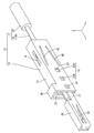
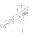
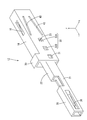
- FIG. Sectional view showing the electric wire with terminal The perspective view which shows a connection cylinder part, an extending part, and an electric wire connection part Side view showing connecting cylinder, extension, and wire connection
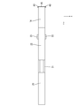
- Sectional drawing which shows the state by which the slide part was hold
- the side view which shows the state by which the electric wire was inserted in the state in which the slide part was hold
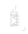
- Sectional drawing which shows the state by which the electric wire was inserted in the state by which the slide part was hold
- the electric wire with terminal 10 includes an electric wire 11 and a female terminal 12 (an example of a terminal) connected to the electric wire 11.
- symbol may be attached
- the electric wire 11 includes a core wire 13 and an insulating coating 35 made of an insulating synthetic resin that covers the outer periphery of the core wire 13.
- a small-diameter core wire 13A having a relatively small diameter and a large-diameter core wire 13B having a relatively large diameter can be selected.
- a metal which comprises the core wire 13 it can select suitably from arbitrary metals as needed, such as copper, a copper alloy, aluminum, an aluminum alloy.
- the core wire 13 according to the present embodiment is made of copper or a copper alloy.
- the core wire 13 may be a stranded wire formed by twisting a plurality of metal strands, or may be a single core wire made of one rod-shaped metal material.
- the core wire 13 which concerns on this embodiment consists of a single core wire.
- the female terminal 12 includes an electric wire connecting portion 19 having a first holding portion 14 (an example of a holding portion) and a second holding portion 15 (an example of a holding portion) that hold the core wire 13 of the electric wire 11. And a slide part 18 slidably attached to the electric wire connection part 19.
- the female terminal 12 is made of a conductive metal material. As a metal which comprises the female terminal 12, it can select suitably from arbitrary metals as needed, such as copper, copper alloy, aluminum, aluminum alloy.
- the terminal according to the present embodiment is made of copper or a copper alloy.
- the female terminal 12 can be formed by a known method such as cutting, casting, or pressing.
- the female terminal 12 has a connecting cylinder portion 20 into which a male terminal (not shown) is inserted.
- the connecting tube portion 20 has a rectangular tube shape extending in the front-rear direction.
- the connecting cylinder part 20 is open forward and backward.
- An elastic contact piece 36 that protrudes inward of the connection cylinder part 20 is provided on the left side wall of the connection cylinder part 20.
- the elastic contact piece 36 extends forward from a position near the rear end portion of the connecting cylinder portion.
- the elastic contact piece 36 elastically contacts the male terminal, whereby the male terminal and the female terminal 12 are electrically connected.
- the rear end portion of the connecting tube portion 20 is connected to an extending portion 21 extending rearward.
- the wire connecting portion 19 is connected to the rear end portion of the extending portion 21.
- the electric wire connecting portion 19 includes a base portion 22 and a first holding portion 14 and a second holding portion 15 that extend rearward (an example of the extending direction) from the rear end portion of the base portion 22.
- the extended portion 21 is formed to open upward. Thereby, the core wire 13 arranged inside the extending portion 21 can be viewed from above.
- the base 22 has a rectangular tube shape extending in the front-rear direction.
- the base 22 opens forward and backward.
- the first clamping part 14 extends obliquely upward and rearward (an example of the extending direction).
- the first extending end portion 46 of the first sandwiching portion 14 is located above the rear end portion of the base portion 22.
- the first extending end portion 46 of the first sandwiching portion 14 is disposed at a position that is wider than the rear end portion of the base portion 22 in the front-rear direction.
- the 1st clamping part 14 has comprised the plate shape elongated in the front-back direction.
- the 1st clamping part 14 is formed so that bending deformation is possible about the plate
- Two first bosses 40 projecting outward in the left-right direction are provided on the left and right ends of the first extending end 46 of the first clamping part 14.
- the projecting dimension of the first boss 40 in the left-right direction from the side edge of the first clamping part is set to be substantially the same as the thickness dimension of the left and right side walls of the slide part 18. “Substantially the same” includes the case where the protruding dimension of the first boss 40 and the thickness dimension of the left and right side walls of the slide portion 18 are the same, and the case where the first boss 40 is recognized to be substantially the same even if it is not the same.
- the lower surface of the first clamping unit 14 is a first contact surface 24 that contacts the core wire 13.
- a first protrusion 25 that protrudes downward from the first contact surface 24 is formed at a position near the front end of the first sandwiching portion 14.
- a plurality of first serrations 26 that extend in the left-right direction and are arranged at intervals in the front-rear direction in the first contact surface 24 of the first holding portion 14 at a position behind the first protrusion 25 are V-shaped grooves. (See FIG. 6).
- the second sandwiching portion 15 extends obliquely downward and rearward (an example of the extending direction) from the rear end portion of the lower wall of the base portion 22.
- the second extending end portion 47 of the second sandwiching portion 15 is positioned below the rear end portion of the base portion 22.
- the second extending end portion 47 of the second sandwiching portion 15 is disposed at a position that is wider than the rear end portion of the base portion 22 in the front-rear direction.
- the 2nd clamping part 15 has comprised the plate shape elongated in the front-back direction.
- the 2nd clamping part 15 is formed so that bending deformation is possible about a plate
- Two left and right end portions of the second extending end portion 47 of the second holding portion 15 are provided with two second bosses 41 protruding outward in the left-right direction.
- the projecting dimension of the second boss 41 in the left-right direction from the side edge of the second clamping part is set to be substantially the same as the thickness dimension of the left and right side walls of the slide part 18.
- substantially the same includes the case where the protruding dimension of the second boss 41 and the thickness dimension of the left and right side walls of the slide portion 18 are the same, and the case where they are recognized to be substantially the same even if they are not the same.
- the upper surface of the second clamping unit 15 is a second contact surface 27 that contacts the core wire 13.
- a second protrusion 28 protruding upward from the second contact surface 27 is provided on the second contact surface 27 of the second sandwiching portion 15 at a position rearward of the rear end portion of the first protrusion of the first sandwiching portion 14. Is formed.
- the slide part 18 has a rectangular tube shape elongated in the front-rear direction, and is open in the front-rear direction.
- the opening on the front side of the slide portion 18 is formed to be the same as or slightly larger than the outer shape of the wire connection portion 19, and the wire connection portion 19 can be inserted.
- the slide portion 18 can be formed of any material such as metal, synthetic resin, ceramic, or the like as necessary.
- a metal which comprises the slide part 18 arbitrary metals can be suitably selected as needed, such as copper, copper alloy, aluminum, aluminum alloy, and stainless steel.
- the slide portion 18 is formed of a metal, it can be formed by any method as necessary, such as cutting, casting, or pressing.
- a jig contact portion 30 protruding upward is provided at the front end portion of the upper wall of the slide portion 18.
- the slide portion 18 slides forward.
- the slide portion 18 is elastically locked with the locking projections 23 at positions on the left side wall and the front end portion of the right side wall of the slide portion 18 so that the slide portion 18 is connected to the electric wire.
- a temporary locking portion 31 that is held at a temporary locking position with respect to the portion 19 is provided.
- the temporary locking portion 31 is formed as a through-hole penetrating the left side wall and the right side wall of the slide portion 18.
- the size of the hole edge of the temporary locking portion 31 is the same as or slightly larger than that of the locking projection 23, and the locking projection 23 can be fitted into the temporary locking portion 31.
- the left side wall and the right side wall of the slide part 18 are respectively elastically locked to the locking projections 23 behind the temporary locking part 31, and the slide part 18 is connected to the wire connection part 19.
- a plurality (two in this embodiment) of main locking portions 32 held at the main locking position are provided side by side in the front-rear direction.
- the main locking portion 32 is formed as a through-hole penetrating the left side wall and the right side wall of the slide portion 18.
- the size of the hole edge of the main locking part 32 is the same as or slightly larger than that of the locking protrusion 23, and the locking protrusion 23 can be fitted into the main locking part 32.
- the main locking portion 32 provided on each side wall of the slide portion 18 includes a large deformation locking portion 32A located on the rear side, and a small deformation locking portion 32B positioned in front of the large deformation locking portion 32A. ,including.
- the locking projection 23 is locked to the large deformation locking portion 32A
- the slide portion 18 is held at the large deformation locking position with respect to the electric wire connection portion 19, and the locking projection 23 is small.
- the slide portion 18 is held at the small deformation locking position with respect to the electric wire connecting portion 19 by being locked to the deformation locking portion 32B.
- a first projection 16 projecting downward is formed on the lower surface of the upper wall of the slide part 18 at a position rearward of the center position in the front-rear direction and extending in the front-rear direction.
- the rear end portion of the first projecting portion 16 extends to a position slightly ahead of the rear end portion of the slide portion 18 material.
- the projecting dimension of the first projecting portion 16 from the upper wall of the slide portion 18 is set so as to increase toward the rear.
- the lower surface of the 1st protrusion part 16 is made into the 1st inclined surface 44 which inclines and descends toward back (an example of a pressurization part and an inclined surface).
- the first inclined surface 44 according to the present embodiment is formed as a flat surface.
- the first inclined surface 44 faces the lower surface of the first clamping unit 14.
- the first inclined surface 44 may be a curved surface.
- a second projecting part 17 projecting upward is formed on the upper surface of the lower wall of the slide part 18 at a position rearward of the central position in the front-rear direction and extending in the front-rear direction.
- the rear end portion of the second projecting portion 17 extends to a position slightly ahead of the rear end portion of the slide portion 18 material.
- the projecting dimension of the second projecting portion 17 from the lower wall of the slide portion 18 is set to increase toward the rear.
- the upper surface of the 2nd protrusion part 17 is made into the 2nd inclined surface 45 which ascends as it goes back (an example of a pressurization part and an inclined surface).
- the second inclined surface 45 according to the present embodiment is formed as a flat surface.
- the second inclined surface 45 is opposed to the upper surface of the second clamping part.
- the second inclined surface 45 may be a curved surface.
- the shapes of the first protrusion 16 and the second protrusion 17 are formed symmetrically in the vertical direction. Thereby, the 1st inclined surface 44 and the 2nd inclined surface 45 are also formed symmetrically about the up-down direction. In addition, the 1st protrusion part 16 and the 2nd protrusion part 17 may be asymmetrical about an up-down direction.
- first guide grooves 42 are formed on the left and right side walls of the slide portion 18 at positions above the center in the vertical direction. Has been.
- the front end portion of the first guide groove 42 extends further forward than the front end portion of the first protrusion.
- the rear end portion of the first guide groove 42 extends rearward from the rear end portion of the first projecting portion.
- the first guide groove 42 according to the present embodiment is formed through the side wall of the slide portion 18. The first guide groove 42 may not penetrate the side wall of the slide portion 18.
- the first guide groove 42 is formed to be inclined downward in a straight line from the front to the rear.
- the 1st guide groove 42 may be formed in the curved downward inclination.
- 2nd guide groove 43 (an example of a pressurization part and a guide groove) is formed in the position below the center about the up-down direction at the both right and left side walls of the slide part 18, respectively.
- the front end portion of the second guide groove 43 extends further forward than the front end portion of the second protrusion.
- the rear end portion of the second guide groove 43 extends rearward from the rear end portion of the second protrusion.
- the second guide groove 43 according to the present embodiment is formed through the side wall of the slide portion 18. Note that the second guide groove 43 may not penetrate the side wall of the slide portion 18.
- the second guide groove 43 is formed to be inclined upward in a straight line from the front to the rear.
- the 2nd guide groove 43 may be formed in the curving downward inclination.
- first guide groove 42 and the second guide groove 43 are formed symmetrically in the vertical direction. Note that the first guide groove 42 and the second guide groove 43 may be asymmetric in the vertical direction.
- FIGS. 10 to 12 show a state in which the slide portion 18 is temporarily locked to the wire connecting portion 19.
- the locking protrusion 23 of the electric wire connection portion 19 is fitted inside the temporary locking portion 31 of the slide portion 18.
- the front half portion of the slide portion 18 is approximately two thirds long from the rear end portion in the front-rear direction of the electric wire connection portion 19. It is externally fitted up to the size.
- the rear end portion of the first clamping portion 14 is located in front of the front end portion of the first projecting portion 16.
- the rear end portion of the second sandwiching portion 15 is located in front of the front end portion of the second projecting portion 17.
- the first sandwiching portion 14 and the first projecting portion 16 are not in contact with each other, and the second sandwiching portion 15 and the second projecting portion 17 are not in contact with each other.
- the first boss 40 of the first clamping portion 14 is fitted into the first guide groove 42 of the slide portion 18, and the front end of the first guide groove 42. It is located slightly behind the part.
- the second boss 41 of the second sandwiching portion 15 is fitted into the second guide groove 43 of the slide portion 18, and slightly from the front end portion of the second guide groove 43. Located behind.
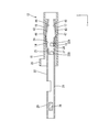
- FIGS. 1 to 2 and FIG. 15 show a state in which the slide portion 18 is permanently locked to the large deformation locking portion 32A of the wire connecting portion 19.
- FIG. The locking projection 23 of the electric wire connection portion 19 is fitted inside the large deformation locking portion 32 ⁇ / b> A of the slide portion 18.
- the slide portion 18 In a state where the slide portion 18 is held at the large deformation locking position with respect to the electric wire connection portion 19, the slide portion 18 completely covers the electric wire connection portion 19 in the front-rear direction.
- the front end portion of the slide portion 18 is located in front of the front end portion of the electric wire connection portion 19, and the rear end portion of the slide portion 18 is located rearward of the rear end portion of the electric wire connection portion 19.
- the 1st protrusion part 16 is contact
- the second projecting portion 17 is in contact with the lower surface of the second sandwiching portion 15 (the surface opposite to the second contact surface 27) from below. Thereby, the 2nd clamping part 15 bends upwards and is contact
- the first boss 40 is located at the rear end portion of the first guide groove 42 in the large deformation locking position. Therefore, when the 1st extension end part 46 of the 1st clamping part 14 deform
- the second boss 41 is located at the rear end of the second guide groove 43.
- the second extending end portion 47 of the second holding portion 15 is deformed upward, so that the second holding portion 15 contacts the small-diameter core wire 13A from above.
- the first sandwiching portion 14 abuts on the first projecting portion 16 from above and the second sandwiching portion 15 abuts on the second projecting portion 17 from below so that the first sandwiching portion 14 and the second sandwiching portion 15 are in contact with each other.
- the small-diameter core wire 13 ⁇ / b> A arranged therebetween is sandwiched between the first sandwiching portion 14 and the second sandwiching portion 15. Thereby, the electric wire 11 and the female terminal 12 are electrically connected.
- the small-diameter core wire 13 ⁇ / b> A is sandwiched between the first protrusion 25 of the first holding part 14 and the second protrusion 28 of the second holding part 15 provided so as to be shifted in the front-rear direction. It is bent in a crank shape. Thereby, the small-diameter core wire 13 ⁇ / b> A is firmly held between the first sandwiching portion 14 and the second sandwiching portion 15.
- the small-diameter core wire 13 ⁇ / b> A is fitted inside the first serration 26 formed on the first contact surface 24. Thereby, the oxide film formed on the surface of the small-diameter core wire 13A is peeled off to expose the metal surface. When the exposed metal surface and the first contact surface 24 come into contact with each other, the electrical resistance between the first sandwiching portion 14 and the small-diameter core wire 13A can be reduced.
- the small diameter core wire 13A is inserted into the second serration 29 formed on the second contact surface 27.
- the oxide film formed on the surface of the small-diameter core wire 13A is peeled off to expose the metal surface.
- the electrical resistance between the second sandwiching portion 15 and the small-diameter core wire 13A can be reduced.
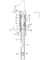
- Full lock state (small deformation lock state) 16 to 17 show a state in which the slide portion 18 is permanently locked to the small deformation locking portion 32B of the electric wire connection portion 19.
- FIG. The locking projection 23 of the electric wire connection portion 19 is fitted inside the small deformation locking portion 32B of the slide portion 18.
- the front end portion of the wire connection portion 19 protrudes forward from the front end portion of the slide portion 18, and the wire connection portion 19.
- the rear end portion is located in front of the rear end portion of the slide portion 18.
- a large-diameter core wire 13B is used in which the diameter dimension of the core wire 13 is larger than that of the small-diameter core wire 13A.
- the 1st protrusion part 16 is contact
- the second projecting portion 17 is in contact with the lower surface of the second sandwiching portion 15 (the surface opposite to the second contact surface 27) from below. Thereby, the 2nd clamping part 15 bends upwards and is contact
- the first boss 40 is located in the vicinity of the center position in the front-rear direction in the first guide groove 42 at the small deformation locking position.
- the second boss 41 In the small deformation locking position, the second boss 41 is located in the vicinity of the center position in the front-rear direction in the second guide groove 43. Thereby, when the 2nd extension end part 47 of the 2nd clamping part 15 deform
- the first sandwiching portion 14 abuts on the first projecting portion 16 from above and the second sandwiching portion 15 abuts on the second projecting portion 17 from below so that the first sandwiching portion 14 and the second sandwiching portion 15 are in contact with each other.
- the large-diameter core wire 13 ⁇ / b> B arranged therebetween is sandwiched between the first sandwiching portion 14 and the second sandwiching portion 15. Thereby, the electric wire 11 and the female terminal 12 are electrically connected.
- the downward deformation amount of the first clamping portion 14 and the upward deformation amount of the second clamping portion 15 are the downward deformation of the first clamping portion 14 in the large deformation locking position. It is smaller than the amount and the upward deformation amount of the second sandwiching portion 15. Thereby, an appropriate pressing force can be applied to the large-diameter core wire 13B.
- the large-diameter core wire 13 ⁇ / b> B is sandwiched between the first protrusion 25 of the first holding part 14 and the second protrusion 28 of the second holding part 15 provided so as to be shifted in the front-rear direction. Therefore, it is bent into a crank shape. Thereby, the large-diameter core wire 13 ⁇ / b> B is firmly held between the first sandwiching portion 14 and the second sandwiching portion 15.
- the large-diameter core wire 13B fits inside the first serration 26 formed on the first contact surface 24. Thereby, the oxide film formed on the surface of the large-diameter core wire 13B is peeled off and the metal surface is exposed. When the exposed metal surface and the first contact surface 24 come into contact with each other, the electrical resistance between the first sandwiching portion 14 and the large-diameter core wire 13B can be reduced.
- the large-diameter core wire 13B is inserted into the second serration 29 formed on the second contact surface 27. Thereby, the oxide film formed on the surface of the large-diameter core wire 13B is peeled off and the metal surface is exposed. When the exposed metal surface and the second contact surface 27 come into contact with each other, the electrical resistance between the second sandwiching portion 15 and the large-diameter core wire 13B can be reduced.
- connection process of female terminal 12 and electric wire 11 An example of a connection process of female terminal 12 and electric wire 11 Then, an example of a connection process of female terminal 12 and electric wire 11 concerning this embodiment is explained. In addition, about the connection process of the female terminal 12 and the electric wire 11, it is not limited to the following description.
- the slide part 18 is externally fitted to the electric wire connection part 19 of the female terminal 12 from behind.
- the rear end portion of the electric wire connecting portion 19 of the female terminal 12 is inserted into the opening on the front side of the slide portion 18, and the slide portion 18 is moved forward.
- the first boss 40 of the first clamping part 14 and the second boss 41 of the second clamping part 15 abut against the opening edge on the front side of the slide part 18 from the front, the left and right side walls of the slide part 18 are laterally moved. Elastically deform outward.
- the slide portion 18 is further moved forward, the locking projection 23 of the wire connection portion 19 comes into contact with the opening edge on the front side of the slide portion 18 from the front. Then, the left and right side walls of the slide portion 18 are elastically deformed outward in the left-right direction.
- the first boss 40 is fitted in the first guide groove 42
- the second boss 41 is fitted in the second guide groove 43, and is locked in the temporary locking portion 31.
- the protrusions 23 are inserted, and the left and right side walls of the slide portion 18 are restored and deformed.
- the locking projection 23 abuts against the hole edge of the temporary locking portion 31 from the front or the rear, so that the slide portion 18 is held at the temporary locking position with respect to the electric wire connection portion 19.
- the first extending end portion 46 of the first sandwiching portion 14 and the second extending end portion 47 of the second sandwiching portion 15 are held at a position expanded with respect to the rear end portion of the base portion 22 ( (See FIGS. 10 to 12).
- the insulation coating 35 is peeled off at the end of the electric wire 11 to expose the small-diameter core wire 13A.
- the exposed small-diameter core wire 13A is inserted from the opening on the rear side of the slide portion 18. Further, the small-diameter core wire 13A is inserted forward so that the front end portion of the small-diameter core wire 13A is positioned inside the extending portion 21.
- the front end portion of the small-diameter core wire 13 ⁇ / b> A is located inside the extended portion 21.
- the jig 34 is brought into contact with the jig abutting portion 30 from the rear and pressed from the rear, thereby moving the slide portion 18 forward. Then, the left and right side walls of the slide portion 18 ride on the locking projections 23 of the wire connection portion 19. As a result, the left and right side walls of the wire connecting portion 19 are elastically deformed inward in the left-right direction.
- the first projecting portion 16 comes into contact with the upper surface of the first holding portion 14 from above and the second projecting portion 17 comes into contact with the lower surface of the second holding portion 15 from below.
- the slide portion 18 by moving the slide portion 18 forward, the first inclined surface 44 of the first projecting portion 16 presses the first sandwiching portion 14 from above to below, and the second inclined surface 45 of the second projecting portion 17 is moved.
- the second clamping unit 15 is pressed from below to above. Accordingly, the first sandwiching portion 14 is deformed downward and the second sandwiching portion 15 is deformed upward, whereby the small-diameter core wire 13A is sandwiched between the first sandwiching portion 14 and the second sandwiching portion 15.
- the female terminal 12 is a female terminal 12 connected to the electric wire 11, and includes a base portion 22, a first holding portion 14 that extends from the base portion 22 in the extending direction, and holds the electric wire 11.
- the electric wire connecting part 19 having the second holding part 15 and the slide part 18 slidable along the extending direction (front-rear direction) in the electric wire connecting part 19 include the first holding part 14 and the slide part 18.
- the first inclined surface 44 and the second inclined surface 45 are provided.
- the wire connecting portion 19 has a first boss 40 and a second boss 41, and the slide portion 18 has a first guide groove 42 with which the first boss 40 is engaged and a second boss 41 with which the second boss 41 is engaged.
- Two guide grooves 43 are provided.
- the amount of deformation of the first clamping unit 14 and the second clamping unit 15 in the direction toward the electric wire 11 can be changed by the amount of movement of the slide unit 18. Thereby, it can respond to the electric wire 11 of a different standard with the female terminal 12 of one standard. As a result, an increase in the number of parts can be suppressed, and the manufacturing cost of the female terminal 12 can be reduced.
- sliding along the extending direction includes the case where the slide portion slides parallel to the extending direction, and even if the sliding part is not parallel to the extending direction, it extends substantially on the basis of the extending direction. This includes the case where the slide part slides according to the direction.
- the slide portion 18 is provided with the first inclined surface 44 facing the first sandwiching portion 14 and the second inclined surface 45 facing the second sandwiching portion 15.
- the first clamping part 14 is pressurized by the first inclined surface 44 and the second clamping part 15 is pressurized by the second inclined surface 45, so that the first clamping part 14 and the second clamping part 15 are reliably pressed. Can exert pressure.
- the first clamping unit 14 has the first boss 40
- the second clamping unit 15 has the second boss 41.
- a first guide groove 42 with which the first boss 40 is engaged is formed in the slide portion
- a second guide groove 43 with which the second boss 41 is engaged is formed.
- the 1st guide groove 42 and the 2nd guide groove 43 are inclined and extended along the extending direction (front-back direction).
- the slide portion 18 has a relative position between the wire connecting portion 19 and the slide portion 18, and the first holding portion 14 and the second holding portion 15 do not pressurize the core wire 13.
- the temporary holding portion 31 held at the locking position, and the relative positions of the wire connecting portion 19 and the slide portion 18 are set to the main locking position where the first holding portion 14 and the second holding portion 15 pressurize the core wire 13.
- the main locking portion 32 is provided, and the main locking portion 32 includes a large deformation locking portion 32A in which the deformation amount of the first holding portion 14 and the second holding portion 15 is relatively large, A small deformation locking portion 32B in which the deformation amount of the first sandwiching portion 14 and the second sandwiching portion 15 is relatively small.
- the second extending end portion 47 is arranged at a position that is wider than the base portion 22 as it goes rearward from the base portion 22.
- the electric wire 11 is electric wire.
- the operation of inserting into the connecting portion 19 can be easily performed. Thereby, the efficiency of the connection work of the female terminal 12 and the electric wire 11 can be improved.
- the terminal is the female terminal 12 in the above embodiment, the terminal is not limited to this, and may be a male terminal, a round terminal, or a splice terminal that connects the plurality of electric wires 11 to each other.
- the electric wire 11 is a covered electric wire, but may be a bare electric wire. Moreover, the electric wire 11 may be a stranded wire in which a plurality of fine metal wires are twisted together.
- the female terminal 12 has the first clamping portion 14 and the second clamping portion 15.
- the present invention is not limited to this, and the number of clamping portions may be one, or three or more. But you can.
- the base portion 22 has a rectangular tube shape, but is not limited thereto, and may be a polygonal tube shape such as a cylindrical shape, a triangular tube shape, or a hexagonal tube shape.
- the slide part 18 material may also be a cylindrical shape, and may be a polygonal cylindrical shape such as a triangular cylindrical shape.
- a pressurizing part is good also as only an inclined surface. Moreover, it is good also as only a guide groove and a boss
- the main locking portion 32 includes the large deformation locking portion 32A and the small deformation locking portion 32B.
- the present locking portion 32 is not limited to this, and depending on the deformation amount of the clamping portion, It is good also as a structure by which three or more book latching
- the present invention is not limited to this, and the appropriate pressing force on the core wire 13 can be obtained by different materials. Even when different, the technique described in the present specification can be suitably used.
Landscapes
- Connections Effected By Soldering, Adhesion, Or Permanent Deformation (AREA)
- Connector Housings Or Holding Contact Members (AREA)
Abstract
A female terminal 12 is connected to an electrical wire 11, and provided with: an electrical wire connection 19 having a base 22, and first and second pinching parts 14, 15 that pinch the electrical wire 11 and that extend from the base 22 in the extending direction; and a slide part 18 that is slidable with respect to the electric wire connection 19 along the extending direction (back-and-forth direction). The slide part 18 has a first slope 44 and a second slope 45 that deform the first and second pinching parts 14, 15 toward the electrical wire 11 and that change the deformation amounts of the first and second pinching parts 14, 15 in accordance with the moving amount of the slide part 18 along the back-and-forth direction with respect to the electrical wire connection 19. The electrical wire connection 19 has a first boss 40 and a second boss 41, and the slide part 18 has a first guide groove 42 with which the first boss 40 is engaged and a second guide groove 43 with which the second boss 41 is engaged.
Description
本明細書に開示された技術は、端子に関する。
The technology disclosed in this specification relates to a terminal.
従来より、電線の端末から露出する芯線に接続される端子が知られている。この端子は、電線の端末から露出する芯線に外側から圧着する圧着部を備える。
Conventionally, a terminal connected to a core wire exposed from the end of an electric wire is known. This terminal includes a crimping portion that crimps the core wire exposed from the end of the electric wire from the outside.
上記の端子を電線に圧着するには、例えば以下のようにする。まず、金属板材をプレス加工することにより所定の形状の端子を成形する。続いて、上下方向に相対移動可能な一対の金型のうち下側に位置する下型の載置部に、端子を載置する。続いて、電線の端末から露出された芯線を、端子金の圧着部に重ねて載置する。その後、一対の金型の一方又は双方を互いに接近する方向に移動させ、上型の圧着部と、下型の載置部との間で圧着部を挟み付けることにより、圧着部を電線の芯線に圧着する。以上により、電線の端末に端子が接続される(特許文献1参照)。
To crimp the above terminal to the wire, for example: First, a terminal having a predetermined shape is formed by pressing a metal plate material. Then, a terminal is mounted on the mounting part of the lower mold located on the lower side of the pair of molds that can move in the vertical direction. Subsequently, the core wire exposed from the end of the electric wire is placed on the crimping portion of the terminal gold. Thereafter, one or both of the pair of molds are moved in a direction approaching each other, and the crimping part is sandwiched between the crimping part of the upper mold and the mounting part of the lower mold, thereby fixing the crimping part to the core wire of the electric wire. Crimp to. Thus, the terminal is connected to the end of the electric wire (see Patent Document 1).
しかしながら上記の技術によれば、電線の芯線に端子の圧着部を圧着するための金型が必要なので、設備投資が必要となり、製造コストが上昇するという問題がある。
However, according to the above technique, since a die for crimping the crimping portion of the terminal to the core wire of the electric wire is necessary, there is a problem that equipment investment is required and the manufacturing cost increases.
上記の問題を解決するために、電線を挟持する一対の挟持部を備えた端子が考えられる。この端子の一対の挟持部の間に芯線を配し、端子から電線が導出される方向から、一対の挟持部を芯線に向かって押圧する押圧部を有するスライド部をスライドさせる。これにより、押圧部は一対の挟持部を芯線に向かって押圧し、一対の挟持部は芯線を挟持することにより、端子と電線とが接続されることが期待された。
In order to solve the above-described problem, a terminal having a pair of clamping parts for clamping the electric wire is conceivable. A core wire is disposed between the pair of holding portions of the terminal, and a slide portion having a pressing portion that presses the pair of holding portions toward the core wire is slid in a direction in which the electric wire is led out from the terminal. Thereby, the pressing part pressed the pair of holding parts toward the core wire, and the pair of holding parts was expected to connect the terminal and the electric wire by holding the core wire.
しかしながら、上記の構成によると、芯線の規格が異なる場合、規格に応じてスライド部の設計を変更しなければならない。すると、部品点数が増加するので、端子の製造コストが増大するという問題が生じる。
However, according to the above configuration, when the standard of the core wire is different, the design of the slide portion must be changed according to the standard. Then, since the number of parts increases, the problem that the manufacturing cost of a terminal increases arises.
本明細書に開示された技術は上記のような事情に基づいて完成されたものであって、端子の製造コストを低減させることを目的とする。
The technology disclosed in the present specification has been completed based on the above-described circumstances, and aims to reduce the manufacturing cost of terminals.
本明細書に開示された技術は、電線に接続される端子であって、基部、及び、前記基部から延出方向に延出されると共に前記電線を挟持する挟持部を有する電線接続部と、前記電線接続部に対して前記延出方向に沿ってスライド可能なスライド部と、を備え、前記電線接続部及び前記スライド部の少なくとも一方は、前記挟持部を前記電線に向けて変形させると共に、前記延出方向に沿う前記スライド部の前記電線接続部に対する移動量に応じて前記挟持部の変形量を変化させる加圧部を有する。
The technology disclosed in the present specification is a terminal connected to an electric wire, and includes a base, and an electric wire connecting portion that extends in the extending direction from the base and has a holding portion that holds the electric wire, A slide part that is slidable along the extending direction with respect to the electric wire connection part, and at least one of the electric wire connection part and the slide part deforms the clamping part toward the electric wire, and A pressurizing unit configured to change a deformation amount of the clamping unit according to an amount of movement of the slide unit along the extending direction with respect to the wire connecting unit;
上記の構成によれば、挟持部の、電線に向かう方向の変形量を、スライド部の移動量によって変化させることができる。これにより、異なる規格の電線に対して、1つの規格の端子で対応することができる。この結果、部品点数が増加することを抑制できるので、端子の製造コストを低減することができる。
According to the above configuration, the amount of deformation of the clamping portion in the direction toward the electric wire can be changed by the amount of movement of the slide portion. Thereby, it can respond to the electric wire of a different standard with the terminal of one standard. As a result, it is possible to suppress an increase in the number of parts, thereby reducing the manufacturing cost of the terminals.
なお、延出方向に沿ってスライド可能とは、スライド部が延出方向に平行にスライドする場合を含むと共に、延出方向に平行でない場合であっても、延出方向を基準として概ね延出方向に従ってスライド部がスライドする場合を含む。
Note that “slidable along the extending direction” includes the case where the slide portion slides parallel to the extending direction, and even if the sliding part is not parallel to the extending direction, it extends substantially on the basis of the extending direction. This includes the case where the slide part slides according to the direction.
本明細書に開示された技術の実施態様としては以下の態様が好ましい。
The following embodiments are preferred as embodiments of the technology disclosed in this specification.
前記加圧部は、前記スライド部のうち前記挟持部と対向する面に設けられて、前記延出方向に沿って傾斜する傾斜面を含むことが好ましい。
It is preferable that the pressurizing unit includes an inclined surface that is provided on a surface of the slide unit that faces the clamping unit and is inclined along the extending direction.
上記の構成によれば、スライド部に設けられた傾斜面によって挟持部を加圧することができるので、挟持部に対して確実に押圧力を及ぼすことができる。
According to the above configuration, the clamping part can be pressurized by the inclined surface provided on the slide part, and therefore, a pressing force can be reliably exerted on the clamping part.
前記加圧部は、前記挟持部から前記スライド部に向かって突出するボスと、前記スライド部に設けられて前記ボスを受け入れるガイド溝と、を含み、
前記ガイド溝は前記延出方向に沿って傾斜して延びていることが好ましい。 The pressurizing part includes a boss projecting from the clamping part toward the slide part, and a guide groove provided on the slide part and receiving the boss,
It is preferable that the guide groove extends while being inclined along the extending direction.
前記ガイド溝は前記延出方向に沿って傾斜して延びていることが好ましい。 The pressurizing part includes a boss projecting from the clamping part toward the slide part, and a guide groove provided on the slide part and receiving the boss,
It is preferable that the guide groove extends while being inclined along the extending direction.
上記の構成によれば、ガイド溝の形状を調節することにより、挟持部の変形量を容易に調節することができる。
According to the above configuration, the deformation amount of the sandwiching portion can be easily adjusted by adjusting the shape of the guide groove.
前記電線接続部及び前記スライド部の少なくとも一方には、前記電線接続部と前記スライド部との相対的な位置を前記挟持部が前記芯線を加圧しない仮係止位置に保持する仮係止部と、前記電線接続部と前記スライド部との相対的な位置を前記挟持部が前記芯線を加圧する本係止位置に保持する本係止部と、が設けられており、前記本係止部は、前記挟持部の変形量が比較的に大きな大変形係止部と、前記挟持部の変形量が比較的に小さな小変形係止部と、を有することが好ましい。
At least one of the wire connection portion and the slide portion includes a temporary locking portion that holds a relative position between the wire connection portion and the slide portion at a temporary locking position where the holding portion does not pressurize the core wire. And a main locking portion that holds the relative position between the wire connecting portion and the slide portion at a final locking position where the clamping portion pressurizes the core wire. It is preferable to have a large deformation locking portion with a relatively large deformation amount of the clamping portion and a small deformation locking portion with a relatively small deformation amount of the clamping portion.
上記の構成によれば、電線接続部とスライド部とを、大変形係止部で係止させるか、小変形係止部で係止させるかにより、異なる規格の電線に対応できる。
According to the above configuration, it is possible to cope with electric wires of different standards depending on whether the wire connecting portion and the slide portion are locked by the large deformation locking portion or the small deformation locking portion.
前記スライド部が前記電線接続部に対して前記仮係止位置に保持された状態で、前記挟持部の延出端部は、前記延出方向について前記基部から前記延出端部に向かうに従って、前記基部よりも拡開した位置に配されていることが好ましい。
In the state where the slide portion is held at the temporary locking position with respect to the wire connecting portion, the extending end portion of the clamping portion is directed from the base portion to the extending end portion in the extending direction. It is preferable that it is arranged at a position that is wider than the base.
上記の構成によれば、挟持部の延出端部が基部よりも拡開しているので、電線を電線接続部に挿入する作業を容易に行うことができる。これにより、端子と電線との接続作業の効率を向上させることができる。
According to the above configuration, since the extending end of the sandwiching portion is wider than the base, the operation of inserting the electric wire into the electric wire connecting portion can be easily performed. Thereby, the efficiency of the connection operation | work of a terminal and an electric wire can be improved.
本明細書に開示された技術によれば、端子の製造コストを低減させることができる。
According to the technique disclosed in this specification, the manufacturing cost of the terminal can be reduced.
<実施形態1>
本明細書に開示された技術の実施形態1を、図1から図17を参照しつつ説明する。本実施形態に係る端子付き電線10は、電線11と、電線11に接続された雌端子12(端子の一例)と、を備える。以下の説明では、Z方向を上方とし、Y方向を前方とし、X方向を左方として説明する。また、複数の同一部材については、一部の部材にのみ符号を付し、他の部材については符号を省略する場合がある。 <Embodiment 1>
A first embodiment of the technology disclosed in this specification will be described with reference to FIGS. The electric wire withterminal 10 according to the present embodiment includes an electric wire 11 and a female terminal 12 (an example of a terminal) connected to the electric wire 11. In the following description, it is assumed that the Z direction is upward, the Y direction is front, and the X direction is left. Moreover, about several same members, a code | symbol may be attached | subjected only to some members, and a code | symbol may be abbreviate | omitted about another member.
本明細書に開示された技術の実施形態1を、図1から図17を参照しつつ説明する。本実施形態に係る端子付き電線10は、電線11と、電線11に接続された雌端子12(端子の一例)と、を備える。以下の説明では、Z方向を上方とし、Y方向を前方とし、X方向を左方として説明する。また、複数の同一部材については、一部の部材にのみ符号を付し、他の部材については符号を省略する場合がある。 <Embodiment 1>
A first embodiment of the technology disclosed in this specification will be described with reference to FIGS. The electric wire with
電線11
図1に示すように、電線11は、芯線13と、芯線13の外周を覆う絶縁性の合成樹脂からなる絶縁被覆35と、を備える。芯線13としては、直径が比較的小さな小径芯線13Aと、直径が比較的大きな大径芯線13Bとを、選択できる。芯線13を構成する金属としては、銅、銅合金、アルミニウム、アルミニウム合金等、必要に応じて任意の金属から適宜に選択することができる。本実施形態に係る芯線13は銅、又は銅合金からなる。芯線13は、複数の金属素線を撚り合わせてなる撚り線でもよく、1つの棒状の金属材料からなる単芯線でもよい。本実施形態に係る芯線13は単芯線からなる。Electric wire 11
As shown in FIG. 1, theelectric wire 11 includes a core wire 13 and an insulating coating 35 made of an insulating synthetic resin that covers the outer periphery of the core wire 13. As the core wire 13, a small-diameter core wire 13A having a relatively small diameter and a large-diameter core wire 13B having a relatively large diameter can be selected. As a metal which comprises the core wire 13, it can select suitably from arbitrary metals as needed, such as copper, a copper alloy, aluminum, an aluminum alloy. The core wire 13 according to the present embodiment is made of copper or a copper alloy. The core wire 13 may be a stranded wire formed by twisting a plurality of metal strands, or may be a single core wire made of one rod-shaped metal material. The core wire 13 which concerns on this embodiment consists of a single core wire.
図1に示すように、電線11は、芯線13と、芯線13の外周を覆う絶縁性の合成樹脂からなる絶縁被覆35と、を備える。芯線13としては、直径が比較的小さな小径芯線13Aと、直径が比較的大きな大径芯線13Bとを、選択できる。芯線13を構成する金属としては、銅、銅合金、アルミニウム、アルミニウム合金等、必要に応じて任意の金属から適宜に選択することができる。本実施形態に係る芯線13は銅、又は銅合金からなる。芯線13は、複数の金属素線を撚り合わせてなる撚り線でもよく、1つの棒状の金属材料からなる単芯線でもよい。本実施形態に係る芯線13は単芯線からなる。
As shown in FIG. 1, the
雌端子12
図2に示すように、雌端子12は、電線11の芯線13を挟持する第1挟持部14(挟持部の一例)及び第2挟持部15(挟持部の一例)を有する電線接続部19と、電線接続部19にスライド可能に取り付けられたスライド部18と、を備える。Female terminal 12
As shown in FIG. 2, thefemale terminal 12 includes an electric wire connecting portion 19 having a first holding portion 14 (an example of a holding portion) and a second holding portion 15 (an example of a holding portion) that hold the core wire 13 of the electric wire 11. And a slide part 18 slidably attached to the electric wire connection part 19.
図2に示すように、雌端子12は、電線11の芯線13を挟持する第1挟持部14(挟持部の一例)及び第2挟持部15(挟持部の一例)を有する電線接続部19と、電線接続部19にスライド可能に取り付けられたスライド部18と、を備える。
As shown in FIG. 2, the
雌端子12は導電性の金属材料からなる。雌端子12を構成する金属としては、銅、銅合金、アルミニウム、アルミニウム合金等、必要に応じて任意の金属から適宜に選択することができる。本実施形態に係る端子は銅、又は銅合金からなる。雌端子12は、切削加工、鋳造、プレス加工等、公知の手法により形成することができる。
The female terminal 12 is made of a conductive metal material. As a metal which comprises the female terminal 12, it can select suitably from arbitrary metals as needed, such as copper, copper alloy, aluminum, aluminum alloy. The terminal according to the present embodiment is made of copper or a copper alloy. The female terminal 12 can be formed by a known method such as cutting, casting, or pressing.
雌端子12は、図示しない雄端子が挿入される接続筒部20を有する。接続筒部20は前後方向に延びる角筒状をなしている。接続筒部20は前方及び後方に開口している。接続筒部20の左側壁には、接続筒部20の内方に突出する弾性接触片36が設けられている。弾性接触片36は、接続筒部の後端部寄りの位置から、前方に延出されている。弾性接触片36が雄端子に弾性的に接触することにより、雄端子と雌端子12とが電気的に接続されるようになっている。
The female terminal 12 has a connecting cylinder portion 20 into which a male terminal (not shown) is inserted. The connecting tube portion 20 has a rectangular tube shape extending in the front-rear direction. The connecting cylinder part 20 is open forward and backward. An elastic contact piece 36 that protrudes inward of the connection cylinder part 20 is provided on the left side wall of the connection cylinder part 20. The elastic contact piece 36 extends forward from a position near the rear end portion of the connecting cylinder portion. The elastic contact piece 36 elastically contacts the male terminal, whereby the male terminal and the female terminal 12 are electrically connected.
接続筒部20の後端部には、後方に延びる延設部21が連なっている。この延設部21の後端部には、電線接続部19が連なっている。電線接続部19は、基部22と、基部22の後端部から後方(延出方向の一例)に延出された第1挟持部14及び第2挟持部15と、を備える。
The rear end portion of the connecting tube portion 20 is connected to an extending portion 21 extending rearward. The wire connecting portion 19 is connected to the rear end portion of the extending portion 21. The electric wire connecting portion 19 includes a base portion 22 and a first holding portion 14 and a second holding portion 15 that extend rearward (an example of the extending direction) from the rear end portion of the base portion 22.
延設部21は上方に開口して形成されている。これにより、延設部21の内部に配された芯線13を上方から視認可能になっている。
The extended portion 21 is formed to open upward. Thereby, the core wire 13 arranged inside the extending portion 21 can be viewed from above.
基部22は、前後方向に延びる角筒状をなしている。基部22は前方及び後方に開口している。基部22の左側壁、及び右側壁には、それぞれ、左右方向に突出する係止突起23が設けられている(図5参照)。
The base 22 has a rectangular tube shape extending in the front-rear direction. The base 22 opens forward and backward. On the left side wall and the right side wall of the base 22, there are provided locking projections 23 that protrude in the left-right direction (see FIG. 5).
図4に示すように、基部22の上壁の後端部からは、第1挟持部14が斜め上後方(延出方向の一例)に延出されている。第1挟持部14の第1延出端部46は、基部22の後端部よりも上方に位置している。換言すると、第1挟持部14の第1延出端部46は、基部22の後端部よりも前後方向について拡開された位置に配されている。第1挟持部14は前後方向に細長く延びる板状をなしている。第1挟持部14は、板厚方向(上下方向)について撓み変形可能に形成されている。
As shown in FIG. 4, from the rear end of the upper wall of the base 22, the first clamping part 14 extends obliquely upward and rearward (an example of the extending direction). The first extending end portion 46 of the first sandwiching portion 14 is located above the rear end portion of the base portion 22. In other words, the first extending end portion 46 of the first sandwiching portion 14 is disposed at a position that is wider than the rear end portion of the base portion 22 in the front-rear direction. The 1st clamping part 14 has comprised the plate shape elongated in the front-back direction. The 1st clamping part 14 is formed so that bending deformation is possible about the plate | board thickness direction (up-down direction).
第1挟持部14の第1延出端部46の左右両端部には、左右方向の外方に突出する2つの第1ボス40が設けられている。第1ボス40の、第1挟持部の側縁からの左右方向への突出寸法は、スライド部18の左右両側壁の厚さ寸法とほぼ同じに設定されている。ほぼ同じとは、第1ボス40の突出寸法とスライド部18の左右両側壁の厚さ寸法が同じ場合を含むと共に、同じでない場合でも実質的に同じと認められる程度である場合を含む。
Two first bosses 40 projecting outward in the left-right direction are provided on the left and right ends of the first extending end 46 of the first clamping part 14. The projecting dimension of the first boss 40 in the left-right direction from the side edge of the first clamping part is set to be substantially the same as the thickness dimension of the left and right side walls of the slide part 18. “Substantially the same” includes the case where the protruding dimension of the first boss 40 and the thickness dimension of the left and right side walls of the slide portion 18 are the same, and the case where the first boss 40 is recognized to be substantially the same even if it is not the same.
第1挟持部14の下面は、芯線13と接触する第1接触面24とされる。第1挟持部14の前端部寄りの位置には、第1接触面24から下方に突出する第1突起25が形成されている。第1挟持部14の第1接触面24のうち、第1突起25よりも後方の位置には、左右方向に延びると共に前後方向に間隔を空けて並ぶ複数の第1セレーション26が、V字溝状に形成されている(図6参照)。
The lower surface of the first clamping unit 14 is a first contact surface 24 that contacts the core wire 13. A first protrusion 25 that protrudes downward from the first contact surface 24 is formed at a position near the front end of the first sandwiching portion 14. A plurality of first serrations 26 that extend in the left-right direction and are arranged at intervals in the front-rear direction in the first contact surface 24 of the first holding portion 14 at a position behind the first protrusion 25 are V-shaped grooves. (See FIG. 6).
図4に示すように、基部22の下壁の後端部からは、第2挟持部15が斜め下後方(延出方向の一例)に延出されている。第2挟持部15の第2延出端部47は、基部22の後端部よりも下方に位置している。換言すると、第2挟持部15の第2延出端部47は、基部22の後端部よりも前後方向について拡開された位置に配されている。第2挟持部15は前後方向に細長く延びる板状をなしている。第2挟持部15は、板厚方向(上下方向)について撓み変形可能に形成されている。
As shown in FIG. 4, the second sandwiching portion 15 extends obliquely downward and rearward (an example of the extending direction) from the rear end portion of the lower wall of the base portion 22. The second extending end portion 47 of the second sandwiching portion 15 is positioned below the rear end portion of the base portion 22. In other words, the second extending end portion 47 of the second sandwiching portion 15 is disposed at a position that is wider than the rear end portion of the base portion 22 in the front-rear direction. The 2nd clamping part 15 has comprised the plate shape elongated in the front-back direction. The 2nd clamping part 15 is formed so that bending deformation is possible about a plate | board thickness direction (up-down direction).
第2挟持部15の第2延出端部47の左右両端部には、左右方向の外方に突出する2つの第2ボス41が設けられている。第2ボス41の、第2挟持部の側縁からの左右方向への突出寸法は、スライド部18の左右両側壁の厚さ寸法とほぼ同じに設定されている。ほぼ同じとは、第2ボス41の突出寸法とスライド部18の左右両側壁の厚さ寸法が同じ場合を含むと共に、同じでない場合でも実質的に同じと認められる程度である場合を含む。
Two left and right end portions of the second extending end portion 47 of the second holding portion 15 are provided with two second bosses 41 protruding outward in the left-right direction. The projecting dimension of the second boss 41 in the left-right direction from the side edge of the second clamping part is set to be substantially the same as the thickness dimension of the left and right side walls of the slide part 18. The term “substantially the same” includes the case where the protruding dimension of the second boss 41 and the thickness dimension of the left and right side walls of the slide portion 18 are the same, and the case where they are recognized to be substantially the same even if they are not the same.
第2挟持部15の上面は、芯線13と接触する第2接触面27とされる。第2挟持部15の第2接触面27には、第1挟持部14の第1突部の後端部よりも後方の位置に、第2接触面27から上方に突出する第2突起28が形成されている。第2突起28の上面には、左右方向に延びると共に前後方向に間隔を空けて並ぶ複数の第2セレーション29が、V字溝状に形成されている(図6参照)。
The upper surface of the second clamping unit 15 is a second contact surface 27 that contacts the core wire 13. A second protrusion 28 protruding upward from the second contact surface 27 is provided on the second contact surface 27 of the second sandwiching portion 15 at a position rearward of the rear end portion of the first protrusion of the first sandwiching portion 14. Is formed. On the upper surface of the second protrusion 28, a plurality of second serrations 29 extending in the left-right direction and arranged at intervals in the front-rear direction are formed in a V-shaped groove shape (see FIG. 6).
スライド部18
図7に示すように、スライド部18は前後方向に細長い角筒状をなしており、前後に開口している。スライド部18の前側の開口は、電線接続部19の外形状と同じか、やや大きく形成されており、電線接続部19が挿入可能になっている。スライド部18は、金属、合成樹脂、セラミック等、必要に応じて任意の材料により形成することができる。スライド部18を構成する金属としては、銅、銅合金、アルミニウム、アルミニウム合金、ステンレス鋼等、必要に応じて任意の金属を適宜に選択することができる。スライド部18を金属で形成する場合には、切削加工、鋳造、プレス加工等、必要に応じて任意の手法により形成することができる。Slide part 18
As shown in FIG. 7, theslide part 18 has a rectangular tube shape elongated in the front-rear direction, and is open in the front-rear direction. The opening on the front side of the slide portion 18 is formed to be the same as or slightly larger than the outer shape of the wire connection portion 19, and the wire connection portion 19 can be inserted. The slide portion 18 can be formed of any material such as metal, synthetic resin, ceramic, or the like as necessary. As a metal which comprises the slide part 18, arbitrary metals can be suitably selected as needed, such as copper, copper alloy, aluminum, aluminum alloy, and stainless steel. When the slide portion 18 is formed of a metal, it can be formed by any method as necessary, such as cutting, casting, or pressing.
図7に示すように、スライド部18は前後方向に細長い角筒状をなしており、前後に開口している。スライド部18の前側の開口は、電線接続部19の外形状と同じか、やや大きく形成されており、電線接続部19が挿入可能になっている。スライド部18は、金属、合成樹脂、セラミック等、必要に応じて任意の材料により形成することができる。スライド部18を構成する金属としては、銅、銅合金、アルミニウム、アルミニウム合金、ステンレス鋼等、必要に応じて任意の金属を適宜に選択することができる。スライド部18を金属で形成する場合には、切削加工、鋳造、プレス加工等、必要に応じて任意の手法により形成することができる。
As shown in FIG. 7, the
スライド部18の上壁の前端部には、上方に突出する治具当接部30が設けられている。この治具当接部30が治具34により後方から押圧されることにより、スライド部18が前方にスライドするようになっている。
A jig contact portion 30 protruding upward is provided at the front end portion of the upper wall of the slide portion 18. When the jig contact portion 30 is pressed from behind by the jig 34, the slide portion 18 slides forward.
図7及び図8に示すように、スライド部18の左側壁、及び右側壁の前端部寄りの位置には、それぞれ、係止突起23と弾性的に係止して、スライド部18を電線接続部19に対して仮係止位置に保持する仮係止部31が設けられている。仮係止部31は、スライド部18の左側壁、及び右側壁を貫通する貫通孔として形成されている。仮係止部31の孔縁の大きさは、係止突起23と同じか、やや大きく形成されており、係止突起23が仮係止部31内に嵌入可能になっている。
As shown in FIGS. 7 and 8, the slide portion 18 is elastically locked with the locking projections 23 at positions on the left side wall and the front end portion of the right side wall of the slide portion 18 so that the slide portion 18 is connected to the electric wire. A temporary locking portion 31 that is held at a temporary locking position with respect to the portion 19 is provided. The temporary locking portion 31 is formed as a through-hole penetrating the left side wall and the right side wall of the slide portion 18. The size of the hole edge of the temporary locking portion 31 is the same as or slightly larger than that of the locking projection 23, and the locking projection 23 can be fitted into the temporary locking portion 31.
スライド部18の左側壁、及び右側壁には、それぞれ、仮係止部31よりも後方に、それぞれ、係止突起23と弾性的に係止して、スライド部18を電線接続部19に対して本係止位置に保持する複数(本実施形態では2個)の本係止部32が、前後方向に並んで設けられている。本係止部32は、スライド部18の左側壁、及び右側壁を貫通する貫通孔として形成されている。本係止部32の孔縁の大きさは、係止突起23と同じか、やや大きく形成されており、係止突起23が本係止部32内に嵌入可能になっている。
The left side wall and the right side wall of the slide part 18 are respectively elastically locked to the locking projections 23 behind the temporary locking part 31, and the slide part 18 is connected to the wire connection part 19. A plurality (two in this embodiment) of main locking portions 32 held at the main locking position are provided side by side in the front-rear direction. The main locking portion 32 is formed as a through-hole penetrating the left side wall and the right side wall of the slide portion 18. The size of the hole edge of the main locking part 32 is the same as or slightly larger than that of the locking protrusion 23, and the locking protrusion 23 can be fitted into the main locking part 32.
スライド部18の各側壁に設けられた本係止部32は、後側に位置する大変形係止部32Aと、この大変形係止部32Aよりも前方に位置する小変形係止部32Bと、を含む。係止突起23が大変形係止部32Aに係止することにより、スライド部18は電線接続部19に対して大変形係止位置に保持されるようになっており、係止突起23が小変形係止部32Bに係止することにより、スライド部18は電線接続部19に対して小変形係止位置に保持されるようになっている。
The main locking portion 32 provided on each side wall of the slide portion 18 includes a large deformation locking portion 32A located on the rear side, and a small deformation locking portion 32B positioned in front of the large deformation locking portion 32A. ,including. When the locking projection 23 is locked to the large deformation locking portion 32A, the slide portion 18 is held at the large deformation locking position with respect to the electric wire connection portion 19, and the locking projection 23 is small. The slide portion 18 is held at the small deformation locking position with respect to the electric wire connecting portion 19 by being locked to the deformation locking portion 32B.
第1突出部
図12に示すように、スライド部18の上壁の下面には、前後方向の中央位置よりも後方の位置に、下方に突出する第1突出部16が前後方向に延びて形成されている。第1突出部16の後端部は、スライド部18材の後端部よりもやや前方の位置にまで延びている。第1突出部16の、スライド部18の上壁からの突出寸法は、後方に向かうに従って大きくなるように設定されている。これにより、第1突出部16の下面は、後方に向かうに従って下降傾斜する第1傾斜面44とされる(加圧部、傾斜面の一例)。本実施形態に係る第1傾斜面44は、平坦面として形成されている。第1傾斜面44は第1挟持部14の下面と対向している。なお、第1傾斜面44は湾曲面であってもよい。 First Projection As shown in FIG. 12, afirst projection 16 projecting downward is formed on the lower surface of the upper wall of the slide part 18 at a position rearward of the center position in the front-rear direction and extending in the front-rear direction. Has been. The rear end portion of the first projecting portion 16 extends to a position slightly ahead of the rear end portion of the slide portion 18 material. The projecting dimension of the first projecting portion 16 from the upper wall of the slide portion 18 is set so as to increase toward the rear. Thereby, the lower surface of the 1st protrusion part 16 is made into the 1st inclined surface 44 which inclines and descends toward back (an example of a pressurization part and an inclined surface). The first inclined surface 44 according to the present embodiment is formed as a flat surface. The first inclined surface 44 faces the lower surface of the first clamping unit 14. The first inclined surface 44 may be a curved surface.
図12に示すように、スライド部18の上壁の下面には、前後方向の中央位置よりも後方の位置に、下方に突出する第1突出部16が前後方向に延びて形成されている。第1突出部16の後端部は、スライド部18材の後端部よりもやや前方の位置にまで延びている。第1突出部16の、スライド部18の上壁からの突出寸法は、後方に向かうに従って大きくなるように設定されている。これにより、第1突出部16の下面は、後方に向かうに従って下降傾斜する第1傾斜面44とされる(加圧部、傾斜面の一例)。本実施形態に係る第1傾斜面44は、平坦面として形成されている。第1傾斜面44は第1挟持部14の下面と対向している。なお、第1傾斜面44は湾曲面であってもよい。 First Projection As shown in FIG. 12, a
第2突出部
スライド部18の下壁の上面には、前後方向の中央位置よりも後方の位置に、上方に突出する第2突出部17が前後方向に延びて形成されている。第2突出部17の後端部は、スライド部18材の後端部よりもやや前方の位置にまで延びている。第2突出部17の、スライド部18の下壁からの突出寸法は、後方に向かうに従って大きくなるように設定されている。これにより、第2突出部17の上面は、後方に向かうに従って上昇傾斜する第2傾斜面45とされる(加圧部、傾斜面の一例)。本実施形態に係る第2傾斜面45は、平坦面として形成されている。第2傾斜面45は第2挟持部の上面と対向している。なお、第2傾斜面45は湾曲面であってもよい。 Second Projecting Part A second projectingpart 17 projecting upward is formed on the upper surface of the lower wall of the slide part 18 at a position rearward of the central position in the front-rear direction and extending in the front-rear direction. The rear end portion of the second projecting portion 17 extends to a position slightly ahead of the rear end portion of the slide portion 18 material. The projecting dimension of the second projecting portion 17 from the lower wall of the slide portion 18 is set to increase toward the rear. Thereby, the upper surface of the 2nd protrusion part 17 is made into the 2nd inclined surface 45 which ascends as it goes back (an example of a pressurization part and an inclined surface). The second inclined surface 45 according to the present embodiment is formed as a flat surface. The second inclined surface 45 is opposed to the upper surface of the second clamping part. The second inclined surface 45 may be a curved surface.
スライド部18の下壁の上面には、前後方向の中央位置よりも後方の位置に、上方に突出する第2突出部17が前後方向に延びて形成されている。第2突出部17の後端部は、スライド部18材の後端部よりもやや前方の位置にまで延びている。第2突出部17の、スライド部18の下壁からの突出寸法は、後方に向かうに従って大きくなるように設定されている。これにより、第2突出部17の上面は、後方に向かうに従って上昇傾斜する第2傾斜面45とされる(加圧部、傾斜面の一例)。本実施形態に係る第2傾斜面45は、平坦面として形成されている。第2傾斜面45は第2挟持部の上面と対向している。なお、第2傾斜面45は湾曲面であってもよい。 Second Projecting Part A second projecting
第1突出部16及び第2突出部17の形状は、上下方向について対称に形成されている。これにより、第1傾斜面44と、第2傾斜面45も、上下方向について対称に形成されている。なお、第1突出部16と第2突出部17は、上下方向について非対称であってもよい。
The shapes of the first protrusion 16 and the second protrusion 17 are formed symmetrically in the vertical direction. Thereby, the 1st inclined surface 44 and the 2nd inclined surface 45 are also formed symmetrically about the up-down direction. In addition, the 1st protrusion part 16 and the 2nd protrusion part 17 may be asymmetrical about an up-down direction.
第1ガイド溝42
図8及び図9に示すように、スライド部18の左右両側壁には、それぞれ、上下方向について中央よりも上方の位置に、第1ガイド溝42(加圧部、ガイド溝の一例)が形成されている。第1ガイド溝42の前端部は、第1突出部の前端部よりも前方にまで延びている。また、第1ガイド溝42の後端部は、第1突出部の後端部よりも後方にまで延びている。本実施形態に係る第1ガイド溝42は、スライド部18の側壁を貫通して形成されている。なお、第1ガイド溝42はスライド部18の側壁を貫通していなくてもよい。First guide groove 42
As shown in FIG. 8 and FIG. 9, first guide grooves 42 (an example of a pressure member and a guide groove) are formed on the left and right side walls of theslide portion 18 at positions above the center in the vertical direction. Has been. The front end portion of the first guide groove 42 extends further forward than the front end portion of the first protrusion. Further, the rear end portion of the first guide groove 42 extends rearward from the rear end portion of the first projecting portion. The first guide groove 42 according to the present embodiment is formed through the side wall of the slide portion 18. The first guide groove 42 may not penetrate the side wall of the slide portion 18.
図8及び図9に示すように、スライド部18の左右両側壁には、それぞれ、上下方向について中央よりも上方の位置に、第1ガイド溝42(加圧部、ガイド溝の一例)が形成されている。第1ガイド溝42の前端部は、第1突出部の前端部よりも前方にまで延びている。また、第1ガイド溝42の後端部は、第1突出部の後端部よりも後方にまで延びている。本実施形態に係る第1ガイド溝42は、スライド部18の側壁を貫通して形成されている。なお、第1ガイド溝42はスライド部18の側壁を貫通していなくてもよい。
As shown in FIG. 8 and FIG. 9, first guide grooves 42 (an example of a pressure member and a guide groove) are formed on the left and right side walls of the
第1ガイド溝42は、前方から後方に向かうに従って直線状に下降傾斜して形成されている。なお、第1ガイド溝42は曲線状に下降傾斜して形成されていてもよい。
The first guide groove 42 is formed to be inclined downward in a straight line from the front to the rear. In addition, the 1st guide groove 42 may be formed in the curved downward inclination.
スライド部18の左右両側壁には、それぞれ、上下方向について中央よりも下方の位置に、第2ガイド溝43(加圧部、ガイド溝の一例)が形成されている。第2ガイド溝43の前端部は、第2突出部の前端部よりも前方にまで延びている。また、第2ガイド溝43の後端部は、第2突出部の後端部よりも後方にまで延びている。本実施形態に係る第2ガイド溝43は、スライド部18の側壁を貫通して形成されている。なお、第2ガイド溝43はスライド部18の側壁を貫通していなくてもよい。
2nd guide groove 43 (an example of a pressurization part and a guide groove) is formed in the position below the center about the up-down direction at the both right and left side walls of the slide part 18, respectively. The front end portion of the second guide groove 43 extends further forward than the front end portion of the second protrusion. Further, the rear end portion of the second guide groove 43 extends rearward from the rear end portion of the second protrusion. The second guide groove 43 according to the present embodiment is formed through the side wall of the slide portion 18. Note that the second guide groove 43 may not penetrate the side wall of the slide portion 18.
第2ガイド溝43は、前方から後方に向かうに従って直線状に上昇傾斜して形成されている。なお、第2ガイド溝43は曲線状に下降傾斜して形成されていてもよい。
The second guide groove 43 is formed to be inclined upward in a straight line from the front to the rear. In addition, the 2nd guide groove 43 may be formed in the curving downward inclination.
本実施形態に係る第1ガイド溝42及び第2ガイド溝43の形状は、上下方向について対称に形成されている。なお、第1ガイド溝42及び第2ガイド溝43は、上下方向について非対称であってもよい。
The shapes of the first guide groove 42 and the second guide groove 43 according to the present embodiment are formed symmetrically in the vertical direction. Note that the first guide groove 42 and the second guide groove 43 may be asymmetric in the vertical direction.
仮係止状態
図10~図12に、スライド部18が電線接続部19に仮係止された状態を示す。電線接続部19の係止突起23は、スライド部18の仮係止部31の内部に内嵌されている。スライド部18が電線接続部19に対して仮係止位置に保持された状態では、スライド部18の前半部分は、電線接続部19のうち前後方向について後端部から概ね三分の二の長さ寸法まで、外嵌されている。 Temporary Locking State FIGS. 10 to 12 show a state in which theslide portion 18 is temporarily locked to the wire connecting portion 19. The locking protrusion 23 of the electric wire connection portion 19 is fitted inside the temporary locking portion 31 of the slide portion 18. In a state where the slide portion 18 is held at the temporary locking position with respect to the electric wire connection portion 19, the front half portion of the slide portion 18 is approximately two thirds long from the rear end portion in the front-rear direction of the electric wire connection portion 19. It is externally fitted up to the size.
図10~図12に、スライド部18が電線接続部19に仮係止された状態を示す。電線接続部19の係止突起23は、スライド部18の仮係止部31の内部に内嵌されている。スライド部18が電線接続部19に対して仮係止位置に保持された状態では、スライド部18の前半部分は、電線接続部19のうち前後方向について後端部から概ね三分の二の長さ寸法まで、外嵌されている。 Temporary Locking State FIGS. 10 to 12 show a state in which the
図12に示すように、仮係止状態においては、第1挟持部14の後端部は第1突出部16の前端部よりも前方に位置している。第2挟持部15の後端部は第2突出部17の前端部よりも前方に位置している。換言すると、仮係止状態においては、第1挟持部14と第1突出部16は当接しておらず、第2挟持部15と第2突出部17も当接していない。
As shown in FIG. 12, in the temporarily locked state, the rear end portion of the first clamping portion 14 is located in front of the front end portion of the first projecting portion 16. The rear end portion of the second sandwiching portion 15 is located in front of the front end portion of the second projecting portion 17. In other words, in the temporarily locked state, the first sandwiching portion 14 and the first projecting portion 16 are not in contact with each other, and the second sandwiching portion 15 and the second projecting portion 17 are not in contact with each other.
図11に示すように、仮係止状態においては、第1挟持部14の第1ボス40は、スライド部18の第1ガイド溝42の内部に嵌入しており、第1ガイド溝42の前端部から僅かに後方に位置している。同様に、仮係止状態においては、第2挟持部15の第2ボス41は、スライド部18の第2ガイド溝43の内部に嵌入しており、第2ガイド溝43の前端部から僅かに後方に位置している。
As shown in FIG. 11, in the temporarily locked state, the first boss 40 of the first clamping portion 14 is fitted into the first guide groove 42 of the slide portion 18, and the front end of the first guide groove 42. It is located slightly behind the part. Similarly, in the temporarily locked state, the second boss 41 of the second sandwiching portion 15 is fitted into the second guide groove 43 of the slide portion 18, and slightly from the front end portion of the second guide groove 43. Located behind.
本係止状態(大変形係止状態)
図1~図2、及び図15に、スライド部18が電線接続部19の大変形係止部32Aに本係止された状態を示す。電線接続部19の係止突起23は、スライド部18の大変形係止部32Aの内部に内嵌されている。スライド部18が電線接続部19に対して大変形係止位置に保持された状態では、スライド部18は、電線接続部19を前後方向について完全に覆っている。スライド部18の前端部は電線接続部19の前端部よりも前方に位置しており、スライド部18の後端部は電線接続部19の後端部よりも後方に位置している。 Full locking state (large deformation locking state)
FIGS. 1 to 2 and FIG. 15 show a state in which theslide portion 18 is permanently locked to the large deformation locking portion 32A of the wire connecting portion 19. FIG. The locking projection 23 of the electric wire connection portion 19 is fitted inside the large deformation locking portion 32 </ b> A of the slide portion 18. In a state where the slide portion 18 is held at the large deformation locking position with respect to the electric wire connection portion 19, the slide portion 18 completely covers the electric wire connection portion 19 in the front-rear direction. The front end portion of the slide portion 18 is located in front of the front end portion of the electric wire connection portion 19, and the rear end portion of the slide portion 18 is located rearward of the rear end portion of the electric wire connection portion 19.
図1~図2、及び図15に、スライド部18が電線接続部19の大変形係止部32Aに本係止された状態を示す。電線接続部19の係止突起23は、スライド部18の大変形係止部32Aの内部に内嵌されている。スライド部18が電線接続部19に対して大変形係止位置に保持された状態では、スライド部18は、電線接続部19を前後方向について完全に覆っている。スライド部18の前端部は電線接続部19の前端部よりも前方に位置しており、スライド部18の後端部は電線接続部19の後端部よりも後方に位置している。 Full locking state (large deformation locking state)
FIGS. 1 to 2 and FIG. 15 show a state in which the
スライド部18が電線接続部19の大変形係止部32Aに本係止される場合には、芯線13の直径寸法が比較的に小さな小径芯線13Aが用いられる。
When the slide portion 18 is permanently locked to the large deformation locking portion 32A of the wire connection portion 19, a small-diameter core wire 13A having a relatively small diameter dimension of the core wire 13 is used.
図2に示すように、第1突出部16は、第1挟持部14の上面(第1接触面24と反対側の面)に、上方から当接している。これにより、第1挟持部14は下方に屈曲し、小径芯線13Aに対して上方から当接している。
As shown in FIG. 2, the 1st protrusion part 16 is contact | abutting from the upper surface (surface on the opposite side to the 1st contact surface 24) of the 1st clamping part 14. As shown in FIG. Thereby, the 1st clamping part 14 bends below and is contact | abutted from 13 A of small diameter core wires from upper direction.
第2突出部17は、第2挟持部15の下面(第2接触面27と反対側の面)に、下方から当接している。これにより、第2挟持部15は上方に屈曲し、小径芯線13Aに対して下方から当接している。
The second projecting portion 17 is in contact with the lower surface of the second sandwiching portion 15 (the surface opposite to the second contact surface 27) from below. Thereby, the 2nd clamping part 15 bends upwards and is contact | abutting from 13 A with respect to the small diameter core wire 13A.
また、図15に示すように、大変形係止位置において、第1ボス40は第1ガイド溝42の後端部に位置している。これにより、第1挟持部14の第1延出端部46が下方へ変形することにより、第1挟持部14は小径芯線13Aに対して上方から当接する。
Further, as shown in FIG. 15, the first boss 40 is located at the rear end portion of the first guide groove 42 in the large deformation locking position. Thereby, when the 1st extension end part 46 of the 1st clamping part 14 deform | transforms below, the 1st clamping part 14 is contact | abutted from 13 A of small diameter core wires.
大変形係止位置において、第2ボス41は第2ガイド溝43の後端部に位置している。これにより、第2挟持部15の第2延出端部47が上方へ変形することにより、第2挟持部15は小径芯線13Aに対して上方から当接する。
In the large deformation locking position, the second boss 41 is located at the rear end of the second guide groove 43. As a result, the second extending end portion 47 of the second holding portion 15 is deformed upward, so that the second holding portion 15 contacts the small-diameter core wire 13A from above.
第1挟持部14が上方から第1突出部16に当接すると共に、第2挟持部15が下方から第2突出部17に当接することにより、第1挟持部14と第2挟持部15との間に配された小径芯線13Aは、第1挟持部14と第2挟持部15によって挟持されるようになっている。これにより、電線11と雌端子12とが電気的に接続される。
The first sandwiching portion 14 abuts on the first projecting portion 16 from above and the second sandwiching portion 15 abuts on the second projecting portion 17 from below so that the first sandwiching portion 14 and the second sandwiching portion 15 are in contact with each other. The small-diameter core wire 13 </ b> A arranged therebetween is sandwiched between the first sandwiching portion 14 and the second sandwiching portion 15. Thereby, the electric wire 11 and the female terminal 12 are electrically connected.
図2に示すように、小径芯線13Aは、前後方向にずれて設けられた第1挟持部14の第1突起25と、第2挟持部15の第2突起28との間に挟まれることにより、クランク状に屈曲されている。これにより、小径芯線13Aは、第1挟持部14と第2挟持部15との間に強固に保持されるようになっている。
As shown in FIG. 2, the small-diameter core wire 13 </ b> A is sandwiched between the first protrusion 25 of the first holding part 14 and the second protrusion 28 of the second holding part 15 provided so as to be shifted in the front-rear direction. It is bent in a crank shape. Thereby, the small-diameter core wire 13 </ b> A is firmly held between the first sandwiching portion 14 and the second sandwiching portion 15.
第1挟持部14の第1接触面24が芯線13に押圧されることにより、第1接触面24に形成された第1セレーション26の内部に小径芯線13Aが嵌入する。これにより、小径芯線13Aの表面に形成された酸化被膜が剥がされて金属表面が露出する。露出した金属表面と第1接触面24とが接触することにより、第1挟持部14と小径芯線13Aとの電気抵抗を小さくすることができるようになっている。
When the first contact surface 24 of the first clamping unit 14 is pressed against the core wire 13, the small-diameter core wire 13 </ b> A is fitted inside the first serration 26 formed on the first contact surface 24. Thereby, the oxide film formed on the surface of the small-diameter core wire 13A is peeled off to expose the metal surface. When the exposed metal surface and the first contact surface 24 come into contact with each other, the electrical resistance between the first sandwiching portion 14 and the small-diameter core wire 13A can be reduced.
同様に、第2挟持部15の第2接触面27が小径芯線13Aに押圧されることにより、第2接触面27に形成された第2セレーション29の内部に小径芯線13Aが嵌入する。これにより、小径芯線13Aの表面に形成された酸化被膜が剥がされて金属表面が露出する。露出した金属表面と第2接触面27とが接触することにより、第2挟持部15と小径芯線13Aとの電気抵抗を小さくすることができるようになっている。
Similarly, when the second contact surface 27 of the second holding part 15 is pressed by the small diameter core wire 13A, the small diameter core wire 13A is inserted into the second serration 29 formed on the second contact surface 27. Thereby, the oxide film formed on the surface of the small-diameter core wire 13A is peeled off to expose the metal surface. When the exposed metal surface and the second contact surface 27 come into contact with each other, the electrical resistance between the second sandwiching portion 15 and the small-diameter core wire 13A can be reduced.
本係止状態(小変形係止状態)
図16~図17に、スライド部18が電線接続部19の小変形係止部32Bに本係止された状態を示す。電線接続部19の係止突起23は、スライド部18の小変形係止部32Bの内部に内嵌されている。スライド部18が電線接続部19に対して小変形係止位置に保持された状態では、電線接続部19の前端部は、スライド部18の前端部よりも前方に突出しており、電線接続部19の後端部は、スライド部18の後端部よりも前方に位置している。 Full lock state (small deformation lock state)
16 to 17 show a state in which theslide portion 18 is permanently locked to the small deformation locking portion 32B of the electric wire connection portion 19. FIG. The locking projection 23 of the electric wire connection portion 19 is fitted inside the small deformation locking portion 32B of the slide portion 18. In a state where the slide portion 18 is held at the small deformation locking position with respect to the wire connection portion 19, the front end portion of the wire connection portion 19 protrudes forward from the front end portion of the slide portion 18, and the wire connection portion 19. The rear end portion is located in front of the rear end portion of the slide portion 18.
図16~図17に、スライド部18が電線接続部19の小変形係止部32Bに本係止された状態を示す。電線接続部19の係止突起23は、スライド部18の小変形係止部32Bの内部に内嵌されている。スライド部18が電線接続部19に対して小変形係止位置に保持された状態では、電線接続部19の前端部は、スライド部18の前端部よりも前方に突出しており、電線接続部19の後端部は、スライド部18の後端部よりも前方に位置している。 Full lock state (small deformation lock state)
16 to 17 show a state in which the
スライド部18が電線接続部19の小変形係止部32Bに本係止される場合には、芯線13の直径寸法が小径芯線13Aよりも大径である、大径芯線13Bが用いられる。
When the slide portion 18 is permanently locked to the small deformation locking portion 32B of the wire connection portion 19, a large-diameter core wire 13B is used in which the diameter dimension of the core wire 13 is larger than that of the small-diameter core wire 13A.
図17に示すように、第1突出部16は、第1挟持部14の上面(第1接触面24と反対側の面)に、上方から当接している。これにより、第1挟持部14は下方に屈曲し、大径芯線13Bに対して上方から当接している。
As shown in FIG. 17, the 1st protrusion part 16 is contact | abutting from the upper surface (surface on the opposite side to the 1st contact surface 24) of the 1st clamping part 14. As shown in FIG. Thereby, the 1st clamping part 14 bends below and is contact | abutted from upper direction with respect to the large diameter core wire 13B.
第2突出部17は、第2挟持部15の下面(第2接触面27と反対側の面)に、下方から当接している。これにより、第2挟持部15は上方に屈曲し、大径芯線13Bに対して下方から当接している。
The second projecting portion 17 is in contact with the lower surface of the second sandwiching portion 15 (the surface opposite to the second contact surface 27) from below. Thereby, the 2nd clamping part 15 bends upwards and is contact | abutting from the downward direction with respect to the large diameter core wire 13B.
また、図16に示すように、小変形係止位置において、第1ボス40は第1ガイド溝42のうち、前後方向の中央位置付近に位置している。これにより、第1挟持部14の第1延出端部46が下方へ変形することにより、第1挟持部14は大径芯線13Bに対して上方から当接する。
Further, as shown in FIG. 16, the first boss 40 is located in the vicinity of the center position in the front-rear direction in the first guide groove 42 at the small deformation locking position. Thereby, when the 1st extension end part 46 of the 1st clamping part 14 deform | transforms below, the 1st clamping part 14 contact | abuts from the upper side with respect to the large diameter core wire 13B.
小変形係止位置において、第2ボス41は第2ガイド溝43のうち、前後方向の中央位置付近に位置している。これにより、第2挟持部15の第2延出端部47が上方へ変形することにより、第2挟持部15は大径芯線13Bに対して上方から当接する。
In the small deformation locking position, the second boss 41 is located in the vicinity of the center position in the front-rear direction in the second guide groove 43. Thereby, when the 2nd extension end part 47 of the 2nd clamping part 15 deform | transforms upwards, the 2nd clamping part 15 contact | abuts from the upper side with respect to the large diameter core wire 13B.
第1挟持部14が上方から第1突出部16に当接すると共に、第2挟持部15が下方から第2突出部17に当接することにより、第1挟持部14と第2挟持部15との間に配された大径芯線13Bは、第1挟持部14と第2挟持部15によって挟持されるようになっている。これにより、電線11と雌端子12とが電気的に接続される。
The first sandwiching portion 14 abuts on the first projecting portion 16 from above and the second sandwiching portion 15 abuts on the second projecting portion 17 from below so that the first sandwiching portion 14 and the second sandwiching portion 15 are in contact with each other. The large-diameter core wire 13 </ b> B arranged therebetween is sandwiched between the first sandwiching portion 14 and the second sandwiching portion 15. Thereby, the electric wire 11 and the female terminal 12 are electrically connected.
小変形係止位置においては、第1挟持部14の下方への変形量、及び第2挟持部15の上方への変形量は、大変形係止位置における第1挟持部14の下方への変形量、及び第2挟持部15の上方への変形量よりも小さくなっている。これにより、大径芯線13Bに対して適切な押圧力を加えることができるようになっている。
In the small deformation locking position, the downward deformation amount of the first clamping portion 14 and the upward deformation amount of the second clamping portion 15 are the downward deformation of the first clamping portion 14 in the large deformation locking position. It is smaller than the amount and the upward deformation amount of the second sandwiching portion 15. Thereby, an appropriate pressing force can be applied to the large-diameter core wire 13B.
図17に示すように、大径芯線13Bは、前後方向にずれて設けられた第1挟持部14の第1突起25と、第2挟持部15の第2突起28との間に挟まれることにより、クランク状に屈曲されている。これにより、大径芯線13Bは、第1挟持部14と第2挟持部15との間に強固に保持されるようになっている。
As shown in FIG. 17, the large-diameter core wire 13 </ b> B is sandwiched between the first protrusion 25 of the first holding part 14 and the second protrusion 28 of the second holding part 15 provided so as to be shifted in the front-rear direction. Therefore, it is bent into a crank shape. Thereby, the large-diameter core wire 13 </ b> B is firmly held between the first sandwiching portion 14 and the second sandwiching portion 15.
第1挟持部14の第1接触面24が大径芯線13Bに押圧されることにより、第1接触面24に形成された第1セレーション26の内部に大径芯線13Bが嵌入する。これにより、大径芯線13Bの表面に形成された酸化被膜が剥がされて金属表面が露出する。露出した金属表面と第1接触面24とが接触することにより、第1挟持部14と大径芯線13Bとの電気抵抗を小さくすることができるようになっている。
When the first contact surface 24 of the first clamping unit 14 is pressed against the large-diameter core wire 13B, the large-diameter core wire 13B fits inside the first serration 26 formed on the first contact surface 24. Thereby, the oxide film formed on the surface of the large-diameter core wire 13B is peeled off and the metal surface is exposed. When the exposed metal surface and the first contact surface 24 come into contact with each other, the electrical resistance between the first sandwiching portion 14 and the large-diameter core wire 13B can be reduced.
同様に、第2挟持部15の第2接触面27が大径芯線13Bに押圧されることにより、第2接触面27に形成された第2セレーション29の内部に大径芯線13Bが嵌入する。これにより、大径芯線13Bの表面に形成された酸化被膜が剥がされて金属表面が露出する。露出した金属表面と第2接触面27とが接触することにより、第2挟持部15と大径芯線13Bとの電気抵抗を小さくすることができるようになっている。
Similarly, when the second contact surface 27 of the second clamping unit 15 is pressed by the large-diameter core wire 13B, the large-diameter core wire 13B is inserted into the second serration 29 formed on the second contact surface 27. Thereby, the oxide film formed on the surface of the large-diameter core wire 13B is peeled off and the metal surface is exposed. When the exposed metal surface and the second contact surface 27 come into contact with each other, the electrical resistance between the second sandwiching portion 15 and the large-diameter core wire 13B can be reduced.
雌端子12と電線11の接続工程の一例
続いて、本実施形態に係る雌端子12と電線11との接続工程の一例について説明する。なお、雌端子12と電線11との接続工程については、以下の記載に限定されない。 An example of a connection process offemale terminal 12 and electric wire 11 Then, an example of a connection process of female terminal 12 and electric wire 11 concerning this embodiment is explained. In addition, about the connection process of the female terminal 12 and the electric wire 11, it is not limited to the following description.
続いて、本実施形態に係る雌端子12と電線11との接続工程の一例について説明する。なお、雌端子12と電線11との接続工程については、以下の記載に限定されない。 An example of a connection process of
まず、スライド部18を、雌端子12の電線接続部19に対して、後方から外嵌する。スライド部18の前側の開口内に雌端子12の電線接続部19の後端部を挿入し、スライド部18を前方に移動させる。第1挟持部14の第1ボス40と、第2挟持部15の第2ボス41とが、スライド部18の前側の開口縁に前方から当接すると、スライド部18の左右両側壁が左右方向について外方に弾性変形する。更にスライド部18を前方に移動させると、電線接続部19の係止突起23がスライド部18の前側の開口縁に前方から当接する。すると、スライド部18の左右両側壁が左右方向について外方に弾性変形する。
First, the slide part 18 is externally fitted to the electric wire connection part 19 of the female terminal 12 from behind. The rear end portion of the electric wire connecting portion 19 of the female terminal 12 is inserted into the opening on the front side of the slide portion 18, and the slide portion 18 is moved forward. When the first boss 40 of the first clamping part 14 and the second boss 41 of the second clamping part 15 abut against the opening edge on the front side of the slide part 18 from the front, the left and right side walls of the slide part 18 are laterally moved. Elastically deform outward. When the slide portion 18 is further moved forward, the locking projection 23 of the wire connection portion 19 comes into contact with the opening edge on the front side of the slide portion 18 from the front. Then, the left and right side walls of the slide portion 18 are elastically deformed outward in the left-right direction.
更にスライド部18を前方に移動させると、第1ボス40が第1ガイド溝42内に嵌入し、第2ボス41が第2ガイド溝43内に嵌入し、仮係止部31内に係止突起23が嵌入し、スライド部18の左右両側壁が復帰変形する。これにより、係止突起23が仮係止部31の孔縁部に対して前方又は後方から当接することにより、スライド部18が電線接続部19に対して仮係止位置に保持される。また、第1挟持部14の第1延出端部46と第2挟持部15の第2延出端部47とが、基部22の後端部に対して拡開した位置に保持される(図10~図12参照)。
When the slide portion 18 is further moved forward, the first boss 40 is fitted in the first guide groove 42, the second boss 41 is fitted in the second guide groove 43, and is locked in the temporary locking portion 31. The protrusions 23 are inserted, and the left and right side walls of the slide portion 18 are restored and deformed. As a result, the locking projection 23 abuts against the hole edge of the temporary locking portion 31 from the front or the rear, so that the slide portion 18 is held at the temporary locking position with respect to the electric wire connection portion 19. Further, the first extending end portion 46 of the first sandwiching portion 14 and the second extending end portion 47 of the second sandwiching portion 15 are held at a position expanded with respect to the rear end portion of the base portion 22 ( (See FIGS. 10 to 12).
次に、電線11の端末において絶縁被覆35を皮剥ぎして小径芯線13Aを露出させる。図13~図14に示すように、露出した小径芯線13Aを、スライド部18の後側の開口から挿入する。更に小径芯線13Aを前方に挿入し、小径芯線13Aの前端部が延設部21の内部に位置するようにする。上方から延設部21を視認することにより、小径芯線13Aの前端部が延設部21の内部に位置することを確認することができる。
Next, the insulation coating 35 is peeled off at the end of the electric wire 11 to expose the small-diameter core wire 13A. As shown in FIGS. 13 to 14, the exposed small-diameter core wire 13A is inserted from the opening on the rear side of the slide portion 18. Further, the small-diameter core wire 13A is inserted forward so that the front end portion of the small-diameter core wire 13A is positioned inside the extending portion 21. By visually recognizing the extended portion 21 from above, it can be confirmed that the front end portion of the small-diameter core wire 13 </ b> A is located inside the extended portion 21.
図14に示すように、治具34を、治具当接部30に後方から当接させて、後方から押圧することにより、スライド部18を前方に移動させる。すると、電線接続部19の係止突起23にスライド部18の左右両側壁が乗り上げる。これにより、電線接続部19の左右両側壁が左右方向の内方に弾性変形する。更にスライド部18を前方に移動させると、第1突出部16が第1挟持部14の上面に上方から当接すると共に、第2突出部17が第2挟持部15の下面に下方から当接する。
As shown in FIG. 14, the jig 34 is brought into contact with the jig abutting portion 30 from the rear and pressed from the rear, thereby moving the slide portion 18 forward. Then, the left and right side walls of the slide portion 18 ride on the locking projections 23 of the wire connection portion 19. As a result, the left and right side walls of the wire connecting portion 19 are elastically deformed inward in the left-right direction. When the slide portion 18 is further moved forward, the first projecting portion 16 comes into contact with the upper surface of the first holding portion 14 from above and the second projecting portion 17 comes into contact with the lower surface of the second holding portion 15 from below.
更にスライド部18を前方に移動させることにより、第1突出部16の第1傾斜面44が第1挟持部14を上方から下方へと押圧し、第2突出部17の第2傾斜面45が第2挟持部15を下方から上方へと押圧する。これにより、第1挟持部14が下方へ変形すると共に第2挟持部15が上方へ変形することによって、小径芯線13Aが第1挟持部14と第2挟持部15とによって挟持される。
Further, by moving the slide portion 18 forward, the first inclined surface 44 of the first projecting portion 16 presses the first sandwiching portion 14 from above to below, and the second inclined surface 45 of the second projecting portion 17 is moved. The second clamping unit 15 is pressed from below to above. Accordingly, the first sandwiching portion 14 is deformed downward and the second sandwiching portion 15 is deformed upward, whereby the small-diameter core wire 13A is sandwiched between the first sandwiching portion 14 and the second sandwiching portion 15.
また、第1ボス40が第1ガイド溝42内を後方に移動することにより、第1挟持部14が下方へと変形される。また、第2ボス41が第2ガイド溝43内を後方に移動することにより、第2挟持部15が上方へと変形される。これにより、小径芯線13Aが第1挟持部14と第2挟持部15とによって挟持される。
Further, when the first boss 40 moves rearward in the first guide groove 42, the first clamping portion 14 is deformed downward. Further, when the second boss 41 moves rearward in the second guide groove 43, the second clamping portion 15 is deformed upward. Thereby, the small-diameter core wire 13 </ b> A is sandwiched between the first sandwiching portion 14 and the second sandwiching portion 15.
更にスライド部18を前方に移動させると、大変形係止部32A内に係止突起23が嵌入し、電線接続部19の左右両側壁が復帰変形する。これにより、係止突起23が大変形係止部32Aの孔縁部に対して前方又は後方から当接することにより、スライド部18が電線接続部19に対して大変形係止位置に保持される(図1~図2、及び図15参照)。これにより、雌端子12と電線11との接続作業が完了し、端子付き電線10が完成する。
When the slide portion 18 is further moved forward, the locking projections 23 are inserted into the large deformation locking portion 32A, and the left and right side walls of the wire connecting portion 19 are deformed to return. As a result, the locking projection 23 abuts against the hole edge of the large deformation locking portion 32 </ b> A from the front or the rear, so that the slide portion 18 is held at the large deformation locking position with respect to the wire connection portion 19. (See FIGS. 1-2 and 15). Thereby, the connection work of the female terminal 12 and the electric wire 11 is completed, and the electric wire 10 with a terminal is completed.
一方、雌端子12と、大径芯線13Bを有する電線11とを接続する場合には、スライド部18を電線接続部19に対して、小変形係止位置に保持する以外は上記と同様なので、説明を省略する(図16~図17参照)。
On the other hand, when connecting the female terminal 12 and the electric wire 11 having the large-diameter core wire 13B, it is the same as the above except that the slide portion 18 is held at the small deformation locking position with respect to the electric wire connecting portion 19, Description is omitted (see FIGS. 16 to 17).
本実施形態の作用効果
続いて、本実施形態の作用効果について説明する。本実施形態に係る雌端子12は、電線11に接続される雌端子12であって、基部22、及び、基部22から延出方向に延出されると共に電線11を挟持する第1挟持部14及び第2挟持部15を有する電線接続部19と、電線接続部19に延出方向(前後方向)に沿ってスライド可能なスライド部18と、を備え、スライド部18は、第1挟持部14及び第2挟持部15を電線11に向けて変形させると共に、前後方向に沿うスライド部18の電線接続部19に対する移動量に応じて第1挟持部14及び第2挟持部15の変形量を変化させる、第1傾斜面44、第2傾斜面45を有する。また、電線接続部19は第1ボス40及び第2ボス41を有し、スライド部18は、第1ボス40が係合する第1ガイド溝42を有すると共に第2ボス41が係合する第2ガイド溝43を有する。 Operational Effects of the Present Embodiment Next, operational effects of the present embodiment will be described. Thefemale terminal 12 according to the present embodiment is a female terminal 12 connected to the electric wire 11, and includes a base portion 22, a first holding portion 14 that extends from the base portion 22 in the extending direction, and holds the electric wire 11. The electric wire connecting part 19 having the second holding part 15 and the slide part 18 slidable along the extending direction (front-rear direction) in the electric wire connecting part 19 include the first holding part 14 and the slide part 18. While deforming the 2nd clamping part 15 toward the electric wire 11, the deformation amount of the 1st clamping part 14 and the 2nd clamping part 15 is changed according to the movement amount with respect to the electric wire connection part 19 of the slide part 18 along the front-back direction. The first inclined surface 44 and the second inclined surface 45 are provided. The wire connecting portion 19 has a first boss 40 and a second boss 41, and the slide portion 18 has a first guide groove 42 with which the first boss 40 is engaged and a second boss 41 with which the second boss 41 is engaged. Two guide grooves 43 are provided.
続いて、本実施形態の作用効果について説明する。本実施形態に係る雌端子12は、電線11に接続される雌端子12であって、基部22、及び、基部22から延出方向に延出されると共に電線11を挟持する第1挟持部14及び第2挟持部15を有する電線接続部19と、電線接続部19に延出方向(前後方向)に沿ってスライド可能なスライド部18と、を備え、スライド部18は、第1挟持部14及び第2挟持部15を電線11に向けて変形させると共に、前後方向に沿うスライド部18の電線接続部19に対する移動量に応じて第1挟持部14及び第2挟持部15の変形量を変化させる、第1傾斜面44、第2傾斜面45を有する。また、電線接続部19は第1ボス40及び第2ボス41を有し、スライド部18は、第1ボス40が係合する第1ガイド溝42を有すると共に第2ボス41が係合する第2ガイド溝43を有する。 Operational Effects of the Present Embodiment Next, operational effects of the present embodiment will be described. The
上記の構成によれば、第1挟持部14及び第2挟持部15の、電線11に向かう方向の変形量を、スライド部18の移動量によって変化させることができる。これにより、異なる規格の電線11に対して、1つの規格の雌端子12で対応することができる。この結果、部品点数が増加することを抑制できるので、雌端子12の製造コストを低減することができる。
According to the above configuration, the amount of deformation of the first clamping unit 14 and the second clamping unit 15 in the direction toward the electric wire 11 can be changed by the amount of movement of the slide unit 18. Thereby, it can respond to the electric wire 11 of a different standard with the female terminal 12 of one standard. As a result, an increase in the number of parts can be suppressed, and the manufacturing cost of the female terminal 12 can be reduced.
なお、延出方向に沿ってスライド可能とは、スライド部が延出方向に平行にスライドする場合を含むと共に、延出方向に平行でない場合であっても、延出方向を基準として概ね延出方向に従ってスライド部がスライドする場合を含む。
Note that “slidable along the extending direction” includes the case where the slide portion slides parallel to the extending direction, and even if the sliding part is not parallel to the extending direction, it extends substantially on the basis of the extending direction. This includes the case where the slide part slides according to the direction.
また、本実施形態によれば、スライド部18には、第1挟持部14に対向する第1傾斜面44と、第2挟持部15に対向する第2傾斜面45とが設けられている。第1傾斜面44によって第1挟持部14が加圧され、第2傾斜面45によって第2挟持部15が加圧されることにより、第1挟持部14及び第2挟持部15に確実に押圧力を及ぼすことができる。
Further, according to the present embodiment, the slide portion 18 is provided with the first inclined surface 44 facing the first sandwiching portion 14 and the second inclined surface 45 facing the second sandwiching portion 15. The first clamping part 14 is pressurized by the first inclined surface 44 and the second clamping part 15 is pressurized by the second inclined surface 45, so that the first clamping part 14 and the second clamping part 15 are reliably pressed. Can exert pressure.
また、本実施形態によれば、第1挟持部14は第1ボス40を有し、第2挟持部15は第2ボス41を有する。一方、スライド部には、第1ボス40が係合する第1ガイド溝42が形成されると共に、第2ボス41が係合する第2ガイド溝43が形成されている。第1ガイド溝42及び第2ガイド溝43は延出方向(前後方向)に沿って傾斜して延びている。
Further, according to the present embodiment, the first clamping unit 14 has the first boss 40, and the second clamping unit 15 has the second boss 41. On the other hand, a first guide groove 42 with which the first boss 40 is engaged is formed in the slide portion, and a second guide groove 43 with which the second boss 41 is engaged is formed. The 1st guide groove 42 and the 2nd guide groove 43 are inclined and extended along the extending direction (front-back direction).
上記の構成によれば、第1ガイド溝42及び第2ガイド溝43の形状を調節することにより、第1挟持部及び第2挟持部の変形量を容易に調節することができる。
According to the above configuration, by adjusting the shapes of the first guide groove 42 and the second guide groove 43, it is possible to easily adjust the deformation amounts of the first and second clamping portions.
また、本実施形態によれば、スライド部18には、電線接続部19とスライド部18との相対的な位置を、第1挟持部14及び第2挟持部15が芯線13を加圧しない仮係止位置に保持する仮係止部31と、電線接続部19とスライド部18との相対的な位置を第1挟持部14及び第2挟持部15が芯線13を加圧する本係止位置に保持する本係止部32と、が設けられており、本係止部32は、第1挟持部14及び第2挟持部15の変形量が比較的に大きな大変形係止部32Aと、第1挟持部14及び第2挟持部15の変形量が比較的に小さな小変形係止部32Bと、を有する。
Further, according to the present embodiment, the slide portion 18 has a relative position between the wire connecting portion 19 and the slide portion 18, and the first holding portion 14 and the second holding portion 15 do not pressurize the core wire 13. The temporary holding portion 31 held at the locking position, and the relative positions of the wire connecting portion 19 and the slide portion 18 are set to the main locking position where the first holding portion 14 and the second holding portion 15 pressurize the core wire 13. The main locking portion 32 is provided, and the main locking portion 32 includes a large deformation locking portion 32A in which the deformation amount of the first holding portion 14 and the second holding portion 15 is relatively large, A small deformation locking portion 32B in which the deformation amount of the first sandwiching portion 14 and the second sandwiching portion 15 is relatively small.
上記の構成によれば、電線接続部19とスライド部18とを、大変形係止部32Aで係止させるか、小変形係止部32Bで係止させるかにより、異なる規格の電線11に対応できる。
According to said structure, it respond | corresponds to the electric wire 11 of a different standard depending on whether the electric wire connection part 19 and the slide part 18 are latched by the large deformation | transformation latching | locking part 32A or the small deformation | transformation latching | locking part 32B. it can.
また、本実施形態によれば、スライド部18が電線接続部19に対して仮係止位置に保持された状態で、第1挟持部14の第1延出端部46及び第2挟持部15の第2延出端部47は、基部22から後方に向かうに従って、基部22よりも拡開した位置に配されている。
Further, according to the present embodiment, the first extending end portion 46 and the second holding portion 15 of the first holding portion 14 in a state where the slide portion 18 is held at the temporary locking position with respect to the electric wire connecting portion 19. The second extending end portion 47 is arranged at a position that is wider than the base portion 22 as it goes rearward from the base portion 22.
上記の構成によれば、第1挟持部14の第1延出端部46及び第2挟持部15の第2延出端部47が基部22よりも拡開しているので、電線11を電線接続部19に挿入する作業を容易に行うことができる。これにより、雌端子12と電線11との接続作業の効率を向上させることができる。
According to said structure, since the 1st extension end part 46 of the 1st clamping part 14 and the 2nd extension end part 47 of the 2nd clamping part 15 are expanded rather than the base part 22, the electric wire 11 is electric wire. The operation of inserting into the connecting portion 19 can be easily performed. Thereby, the efficiency of the connection work of the female terminal 12 and the electric wire 11 can be improved.
<他の実施形態>
本明細書に開示された技術は上記記述及び図面によって説明した実施形態に限定されるものではなく、例えば次のような実施形態も本明細書に開示された技術の技術的範囲に含まれる。 <Other embodiments>
The technology disclosed in the present specification is not limited to the embodiments described with reference to the above description and drawings, and for example, the following embodiments are also included in the technical scope of the technology disclosed in the present specification.
(1)上記実施形態においては、端子は雌端子12としたが、これに限られず、雄端子でもよいし、丸端子でもよいし、また、複数の電線11同士を接続するスプライス端子でもよい。
(1) Although the terminal is the female terminal 12 in the above embodiment, the terminal is not limited to this, and may be a male terminal, a round terminal, or a splice terminal that connects the plurality of electric wires 11 to each other.
(2)上記実施形態においては、電線11は被覆電線としたが、裸電線でもよい。また、電線11は、複数の金属細線が撚り合わされた撚り線であってもよい。
(2) In the above embodiment, the electric wire 11 is a covered electric wire, but may be a bare electric wire. Moreover, the electric wire 11 may be a stranded wire in which a plurality of fine metal wires are twisted together.
(3)上記実施形態では、雌端子12は第1挟持部14と第2挟持部15とを有する構成としたが、これに限られず、挟持部は1個でもよいし、また、3個以上でもよい。
(3) In the above embodiment, the female terminal 12 has the first clamping portion 14 and the second clamping portion 15. However, the present invention is not limited to this, and the number of clamping portions may be one, or three or more. But you can.
(4)上記実施形態では、基部22は角筒状としたが、これに限られず、円筒形状、三角筒状、六角筒状等の多角筒状でもよい。また、スライド部18材も円筒形でもよく、また、三角筒状等の多角筒状でもよい。
(4) In the above-described embodiment, the base portion 22 has a rectangular tube shape, but is not limited thereto, and may be a polygonal tube shape such as a cylindrical shape, a triangular tube shape, or a hexagonal tube shape. Moreover, the slide part 18 material may also be a cylindrical shape, and may be a polygonal cylindrical shape such as a triangular cylindrical shape.
(5)加圧部は、傾斜面のみとしてもよい。また、ガイド溝とボスのみとしてもよい。
(5) A pressurizing part is good also as only an inclined surface. Moreover, it is good also as only a guide groove and a boss | hub.
(6)上記実施形態では、本係止部32は、大変形係止部32Aと小変形係止部32Bとを備える構成としたが、これに限られず、挟持部の変形量に応じて、3個以上の本係止部が設けられる構成としてもよい。
(6) In the above embodiment, the main locking portion 32 includes the large deformation locking portion 32A and the small deformation locking portion 32B. However, the present locking portion 32 is not limited to this, and depending on the deformation amount of the clamping portion, It is good also as a structure by which three or more book latching | locking parts are provided.
(7)上記実施形態では、芯線13が、大径芯線13Bと小径芯線13Aである場合について説明したが、これに限られず、芯線13の材質が異なることにより、芯線13に対する適切な押圧力が異なる場合にも、本願明細書に記載された技術を好適に用いることができる。
(7) In the above-described embodiment, the case where the core wire 13 is the large-diameter core wire 13B and the small-diameter core wire 13A has been described. However, the present invention is not limited to this, and the appropriate pressing force on the core wire 13 can be obtained by different materials. Even when different, the technique described in the present specification can be suitably used.
11:電線
12:雌端子
14:第1挟持部
15:第2挟持部
18:スライド部
19:電線接続部
22:基部
31:仮係止部
32A:大変形係止部
32B:小変形係止部
40:第1ボス
41:第2ボス
42:第1ガイド溝
43:第2ガイド溝
44:第1傾斜面
46:第1延出端部
47:第2延出端部
45:第2傾斜面 DESCRIPTION OF SYMBOLS 11: Electric wire 12: Female terminal 14: 1st clamping part 15: 2nd clamping part 18: Slide part 19: Electric wire connection part 22: Base part 31:Temporary latching part 32A: Large deformation latching part 32B: Small deformation latching Portion 40: 1st boss 41: 2nd boss 42: 1st guide groove 43: 2nd guide groove 44: 1st inclined surface 46: 1st extension end part 47: 2nd extension end part 45: 2nd inclination surface
12:雌端子
14:第1挟持部
15:第2挟持部
18:スライド部
19:電線接続部
22:基部
31:仮係止部
32A:大変形係止部
32B:小変形係止部
40:第1ボス
41:第2ボス
42:第1ガイド溝
43:第2ガイド溝
44:第1傾斜面
46:第1延出端部
47:第2延出端部
45:第2傾斜面 DESCRIPTION OF SYMBOLS 11: Electric wire 12: Female terminal 14: 1st clamping part 15: 2nd clamping part 18: Slide part 19: Electric wire connection part 22: Base part 31:
Claims (5)
- 電線に接続される端子であって、
基部、及び、前記基部から延出方向に延出されると共に前記電線を挟持する挟持部を有する電線接続部と、
前記電線接続部に対して前記延出方向に沿ってスライド可能なスライド部と、を備え、
前記電線接続部及び前記スライド部の少なくとも一方は、前記挟持部を前記電線に向けて変形させると共に、前記延出方向に沿う前記スライド部の前記電線接続部に対する移動量に応じて前記挟持部の変形量を変化させる加圧部を有する、端子。 A terminal connected to an electric wire,
A base, and an electric wire connecting portion extending in the extending direction from the base and having a holding portion for holding the electric wire;
A slide portion slidable along the extending direction with respect to the wire connection portion,
At least one of the electric wire connecting portion and the slide portion deforms the holding portion toward the electric wire, and the holding portion of the holding portion according to the amount of movement of the slide portion relative to the electric wire connecting portion along the extending direction. A terminal having a pressurizing portion that changes the amount of deformation. - 前記加圧部は、前記スライド部のうち前記挟持部と対向する面に設けられて、前記延出方向に沿って傾斜する傾斜面を含む、請求項1に記載の端子。 2. The terminal according to claim 1, wherein the pressurizing unit includes an inclined surface that is provided on a surface of the slide unit that faces the clamping unit and is inclined along the extending direction.
- 前記加圧部は、前記挟持部から前記スライド部に向かって突出するボスと、前記スライド部に設けられて前記ボスを受け入れるガイド溝と、を含み、
前記ガイド溝は前記延出方向に沿って傾斜して延びている、請求項1または請求項2に記載の端子。 The pressurizing part includes a boss projecting from the clamping part toward the slide part, and a guide groove provided on the slide part and receiving the boss,
The terminal according to claim 1, wherein the guide groove extends in an inclined manner along the extending direction. - 前記電線接続部及び前記スライド部の少なくとも一方には、前記電線接続部と前記スライド部との相対的な位置を前記挟持部が前記電線を加圧しない仮係止位置に保持する仮係止部と、前記電線接続部と前記スライド部との相対的な位置を前記挟持部が前記電線を加圧する本係止位置に保持する本係止部と、が設けられており、
前記本係止部は、前記挟持部の変形量が比較的に大きな大変形係止部と、前記挟持部の変形量が比較的に小さな小変形係止部と、を有する、請求項1から請求項3のいずれか一項に記載の端子。 At least one of the electric wire connection portion and the slide portion includes a temporary locking portion that holds a relative position between the electric wire connection portion and the slide portion at a temporary locking position where the clamping portion does not pressurize the electric wire. And a main locking portion that holds the relative position between the electric wire connecting portion and the slide portion at a main locking position where the clamping portion pressurizes the electric wire, and
The main locking portion includes a large deformation locking portion with a relatively large deformation amount of the clamping portion and a small deformation locking portion with a relatively small deformation amount of the clamping portion. The terminal according to claim 3. - 前記スライド部が前記電線接続部に対して前記仮係止位置に保持された状態で、前記挟持部の延出端部は、前記延出方向について前記基部から前記延出端部に向かうに従って、前記基部よりも拡開した位置に配されている、請求項4に記載の端子。 In the state where the slide portion is held at the temporary locking position with respect to the wire connecting portion, the extending end portion of the clamping portion is directed from the base portion to the extending end portion in the extending direction. The terminal according to claim 4, wherein the terminal is disposed at a position expanded from the base.
Priority Applications (2)
| Application Number | Priority Date | Filing Date | Title |
|---|---|---|---|
| US16/967,550 US20210234286A1 (en) | 2018-02-15 | 2019-02-04 | Terminal |
| CN201980011874.8A CN111684663B (en) | 2018-02-15 | 2019-02-04 | Terminal with a terminal body |
Applications Claiming Priority (2)
| Application Number | Priority Date | Filing Date | Title |
|---|---|---|---|
| JP2018025419A JP6954170B2 (en) | 2018-02-15 | 2018-02-15 | Terminal |
| JP2018-025419 | 2018-11-21 |
Publications (1)
| Publication Number | Publication Date |
|---|---|
| WO2019159730A1 true WO2019159730A1 (en) | 2019-08-22 |
Family
ID=67619049
Family Applications (1)
| Application Number | Title | Priority Date | Filing Date |
|---|---|---|---|
| PCT/JP2019/003793 WO2019159730A1 (en) | 2018-02-15 | 2019-02-04 | Terminal |
Country Status (4)
| Country | Link |
|---|---|
| US (1) | US20210234286A1 (en) |
| JP (1) | JP6954170B2 (en) |
| CN (1) | CN111684663B (en) |
| WO (1) | WO2019159730A1 (en) |
Cited By (4)
| Publication number | Priority date | Publication date | Assignee | Title |
|---|---|---|---|---|
| WO2020196478A1 (en) * | 2019-03-28 | 2020-10-01 | 株式会社オートネットワーク技術研究所 | Joint connector |
| WO2020196480A1 (en) * | 2019-03-28 | 2020-10-01 | 株式会社オートネットワーク技術研究所 | Joint connector |
| JP2021034307A (en) * | 2019-08-28 | 2021-03-01 | 株式会社オートネットワーク技術研究所 | Terminal and wire with terminal |
| WO2021182373A1 (en) * | 2020-03-12 | 2021-09-16 | 株式会社オートネットワーク技術研究所 | Terminal and electrical wire with terminal |
Families Citing this family (6)
| Publication number | Priority date | Publication date | Assignee | Title |
|---|---|---|---|---|
| JP7133513B2 (en) * | 2019-06-12 | 2022-09-08 | 株式会社オートネットワーク技術研究所 | Terminals and wires with terminals |
| CN113875091A (en) * | 2019-06-12 | 2021-12-31 | 株式会社自动网络技术研究所 | Terminal and electric wire with terminal |
| JP7353922B2 (en) * | 2019-11-07 | 2023-10-02 | 古河電気工業株式会社 | Connection structure, connection structure with housing, and terminal |
| JP7353921B2 (en) | 2019-11-07 | 2023-10-02 | 古河電気工業株式会社 | Connection structure, connection structure with housing, and terminal |
| JP2021190286A (en) * | 2020-05-29 | 2021-12-13 | 株式会社オートネットワーク技術研究所 | Terminal, and electric wire with terminal |
| JP7478057B2 (en) | 2020-07-30 | 2024-05-02 | タイコエレクトロニクスジャパン合同会社 | Electrical terminals |
Citations (4)
| Publication number | Priority date | Publication date | Assignee | Title |
|---|---|---|---|---|
| JPS4998795U (en) * | 1972-12-16 | 1974-08-26 | ||
| US20020119710A1 (en) * | 2001-02-27 | 2002-08-29 | Fci Usa, Inc. | Electrical connector having frame and slidable members |
| JP2011014466A (en) * | 2009-07-03 | 2011-01-20 | Tyco Electronics Japan Kk | Connector |
| JP2015056209A (en) * | 2013-09-10 | 2015-03-23 | ヒロセ電機株式会社 | Terminal for electric connector and electric connector |
Family Cites Families (11)
| Publication number | Priority date | Publication date | Assignee | Title |
|---|---|---|---|---|
| JPS325148Y1 (en) * | 1955-05-25 | 1957-06-12 | ||
| US6688905B2 (en) * | 2001-04-09 | 2004-02-10 | Roger Williams | Field attachable electrical connector and self-tightening method of strain relief |
| DE20119530U1 (en) * | 2001-12-01 | 2002-04-18 | Harting Electric Gmbh & Co Kg | Electrical contact element |
| JP2006049211A (en) * | 2004-08-06 | 2006-02-16 | Three M Innovative Properties Co | Coaxial cable grounding structure as well as connector and its wire connection method |
| US7086897B2 (en) * | 2004-11-18 | 2006-08-08 | John Mezzalingua Associates, Inc. | Compression connector and method of use |
| US20090215306A1 (en) * | 2006-05-26 | 2009-08-27 | Centerpin Technology, Inc. | Electrical connector with compression gores |
| US7934954B1 (en) * | 2010-04-02 | 2011-05-03 | John Mezzalingua Associates, Inc. | Coaxial cable compression connectors |
| JP5274693B1 (en) * | 2012-06-15 | 2013-08-28 | 昌範 木本 | Power cable connector |
| JP2015156285A (en) * | 2014-02-20 | 2015-08-27 | 住友電装株式会社 | connection terminal and wire harness |
| JP6086940B2 (en) * | 2015-06-03 | 2017-03-01 | 株式会社木村電気工業 | Wire connection device |
| CN106025584A (en) * | 2016-05-02 | 2016-10-12 | 胡小青 | Line clamping fittings used for electric power circuit |
-
2018
- 2018-02-15 JP JP2018025419A patent/JP6954170B2/en active Active
-
2019
- 2019-02-04 WO PCT/JP2019/003793 patent/WO2019159730A1/en active Application Filing
- 2019-02-04 CN CN201980011874.8A patent/CN111684663B/en active Active
- 2019-02-04 US US16/967,550 patent/US20210234286A1/en not_active Abandoned
Patent Citations (4)
| Publication number | Priority date | Publication date | Assignee | Title |
|---|---|---|---|---|
| JPS4998795U (en) * | 1972-12-16 | 1974-08-26 | ||
| US20020119710A1 (en) * | 2001-02-27 | 2002-08-29 | Fci Usa, Inc. | Electrical connector having frame and slidable members |
| JP2011014466A (en) * | 2009-07-03 | 2011-01-20 | Tyco Electronics Japan Kk | Connector |
| JP2015056209A (en) * | 2013-09-10 | 2015-03-23 | ヒロセ電機株式会社 | Terminal for electric connector and electric connector |
Cited By (11)
| Publication number | Priority date | Publication date | Assignee | Title |
|---|---|---|---|---|
| WO2020196478A1 (en) * | 2019-03-28 | 2020-10-01 | 株式会社オートネットワーク技術研究所 | Joint connector |
| WO2020196480A1 (en) * | 2019-03-28 | 2020-10-01 | 株式会社オートネットワーク技術研究所 | Joint connector |
| US11942737B2 (en) | 2019-03-28 | 2024-03-26 | Autonetworks Technologies, Ltd. | Joint connector |
| JP2021034307A (en) * | 2019-08-28 | 2021-03-01 | 株式会社オートネットワーク技術研究所 | Terminal and wire with terminal |
| WO2021039359A1 (en) * | 2019-08-28 | 2021-03-04 | 株式会社オートネットワーク技術研究所 | Terminal and electrical wire with terminal |
| CN114270629A (en) * | 2019-08-28 | 2022-04-01 | 株式会社自动网络技术研究所 | Terminal and electric wire with terminal |
| US20220294131A1 (en) * | 2019-08-28 | 2022-09-15 | Autonetworks Technologies, Ltd. | Terminal and wire with terminal |
| JP7216895B2 (en) | 2019-08-28 | 2023-02-02 | 株式会社オートネットワーク技術研究所 | Terminals and wires with terminals |
| CN114270629B (en) * | 2019-08-28 | 2024-04-02 | 株式会社自动网络技术研究所 | Terminal and wire with terminal |
| WO2021182373A1 (en) * | 2020-03-12 | 2021-09-16 | 株式会社オートネットワーク技術研究所 | Terminal and electrical wire with terminal |
| JP7310661B2 (en) | 2020-03-12 | 2023-07-19 | 株式会社オートネットワーク技術研究所 | Terminals and wires with terminals |
Also Published As
| Publication number | Publication date |
|---|---|
| CN111684663A (en) | 2020-09-18 |
| CN111684663B (en) | 2022-08-23 |
| US20210234286A1 (en) | 2021-07-29 |
| JP2019145214A (en) | 2019-08-29 |
| JP6954170B2 (en) | 2021-10-27 |
Similar Documents
| Publication | Publication Date | Title |
|---|---|---|
| WO2019159730A1 (en) | Terminal | |
| WO2019159746A1 (en) | Terminal and electrical wire with terminal | |
| JP5107693B2 (en) | Crimping structure and crimping method | |
| WO2019159714A1 (en) | Electrical wire with terminal | |
| JP2005050736A (en) | Method of manufacturing terminal crimping structure to aluminum wire and aluminum wire with terminal | |
| CN113574738B (en) | Terminal and electric wire with terminal | |
| WO2020250800A1 (en) | Terminal and terminal-equipped wire | |
| WO2021182373A1 (en) | Terminal and electrical wire with terminal | |
| JP6156185B2 (en) | Electric wire with terminal | |
| WO2021241294A1 (en) | Terminal, and electric cable with terminal | |
| WO2020209179A1 (en) | Terminal, and electrical wire with terminal | |
| JP4268006B2 (en) | Terminal crimping structure to aluminum wire and method of manufacturing aluminum wire with terminal | |
| CN114128055B (en) | Terminal and electric wire with terminal | |
| US20220239019A1 (en) | Terminal and terminal wire assembly | |
| JP5008821B2 (en) | Electric wire with terminal and manufacturing method thereof | |
| JP2020205232A (en) | Terminal and wire with the same | |
| WO2017068965A1 (en) | Production method for terminal-equipped electrical wire, crimp tool, and terminal-equipped electrical wire | |
| WO2021039359A1 (en) | Terminal and electrical wire with terminal | |
| WO2020226056A1 (en) | Terminal, and electrical wire with terminal | |
| WO2020209178A1 (en) | Terminal and terminal-equipped wire | |
| JP2010062099A (en) | Terminal metal fitting, and connecting method of terminal metal fitting to electric wire |
Legal Events
| Date | Code | Title | Description |
|---|---|---|---|
| 121 | Ep: the epo has been informed by wipo that ep was designated in this application |
Ref document number: 19753895 Country of ref document: EP Kind code of ref document: A1 |
|
| NENP | Non-entry into the national phase |
Ref country code: DE |
|
| 122 | Ep: pct application non-entry in european phase |
Ref document number: 19753895 Country of ref document: EP Kind code of ref document: A1 |