WO2021039359A1 - Terminal and electrical wire with terminal - Google Patents
Terminal and electrical wire with terminal Download PDFInfo
- Publication number
- WO2021039359A1 WO2021039359A1 PCT/JP2020/030320 JP2020030320W WO2021039359A1 WO 2021039359 A1 WO2021039359 A1 WO 2021039359A1 JP 2020030320 W JP2020030320 W JP 2020030320W WO 2021039359 A1 WO2021039359 A1 WO 2021039359A1
- Authority
- WO
- WIPO (PCT)
- Prior art keywords
- electric wire
- terminal
- facing surface
- fitting
- fitting portion
- Prior art date
Links
Images


Classifications
-
- H—ELECTRICITY
- H01—ELECTRIC ELEMENTS
- H01R—ELECTRICALLY-CONDUCTIVE CONNECTIONS; STRUCTURAL ASSOCIATIONS OF A PLURALITY OF MUTUALLY-INSULATED ELECTRICAL CONNECTING ELEMENTS; COUPLING DEVICES; CURRENT COLLECTORS
- H01R4/00—Electrically-conductive connections between two or more conductive members in direct contact, i.e. touching one another; Means for effecting or maintaining such contact; Electrically-conductive connections having two or more spaced connecting locations for conductors and using contact members penetrating insulation
- H01R4/28—Clamped connections, spring connections
- H01R4/50—Clamped connections, spring connections utilising a cam, wedge, cone or ball also combined with a screw
- H01R4/5083—Clamped connections, spring connections utilising a cam, wedge, cone or ball also combined with a screw using a wedge
-
- H—ELECTRICITY
- H01—ELECTRIC ELEMENTS
- H01R—ELECTRICALLY-CONDUCTIVE CONNECTIONS; STRUCTURAL ASSOCIATIONS OF A PLURALITY OF MUTUALLY-INSULATED ELECTRICAL CONNECTING ELEMENTS; COUPLING DEVICES; CURRENT COLLECTORS
- H01R13/00—Details of coupling devices of the kinds covered by groups H01R12/70 or H01R24/00 - H01R33/00
- H01R13/02—Contact members
-
- H—ELECTRICITY
- H01—ELECTRIC ELEMENTS
- H01R—ELECTRICALLY-CONDUCTIVE CONNECTIONS; STRUCTURAL ASSOCIATIONS OF A PLURALITY OF MUTUALLY-INSULATED ELECTRICAL CONNECTING ELEMENTS; COUPLING DEVICES; CURRENT COLLECTORS
- H01R4/00—Electrically-conductive connections between two or more conductive members in direct contact, i.e. touching one another; Means for effecting or maintaining such contact; Electrically-conductive connections having two or more spaced connecting locations for conductors and using contact members penetrating insulation
- H01R4/10—Electrically-conductive connections between two or more conductive members in direct contact, i.e. touching one another; Means for effecting or maintaining such contact; Electrically-conductive connections having two or more spaced connecting locations for conductors and using contact members penetrating insulation effected solely by twisting, wrapping, bending, crimping, or other permanent deformation
- H01R4/18—Electrically-conductive connections between two or more conductive members in direct contact, i.e. touching one another; Means for effecting or maintaining such contact; Electrically-conductive connections having two or more spaced connecting locations for conductors and using contact members penetrating insulation effected solely by twisting, wrapping, bending, crimping, or other permanent deformation by crimping
- H01R4/183—Electrically-conductive connections between two or more conductive members in direct contact, i.e. touching one another; Means for effecting or maintaining such contact; Electrically-conductive connections having two or more spaced connecting locations for conductors and using contact members penetrating insulation effected solely by twisting, wrapping, bending, crimping, or other permanent deformation by crimping for cylindrical elongated bodies, e.g. cables having circular cross-section
Definitions
- This disclosure relates to terminals and electric wires with terminals.
- an electric wire with a terminal has been known in which a terminal is connected to a core wire exposed from the terminal of the electric wire.
- a terminal for example, there is one provided with a crimping portion for crimping from the outside to a core wire exposed from the end of the electric wire.
- a terminal having a predetermined shape is formed by pressing a metal plate material.
- the terminals are mounted on the mounting portion of the lower mold located on the lower side of the pair of molds that can move relative to each other in the vertical direction.
- the core wire exposed from the terminal of the electric wire is placed on the crimping portion of the terminal.
- one or both of the pair of dies are moved in a direction close to each other, and the crimping portion is sandwiched between the crimping portion of the upper mold and the mounting portion of the lower mold, so that the crimping portion is the core wire of the electric wire. Crimping to.
- the terminal is connected to the terminal of the electric wire (see Patent Document 1).
- the terminal includes a terminal body having a holding portion that can be deformed along the extending direction of the electric wire, and a sliding portion that can move with respect to the terminal body along the extending direction of the electric wire.
- the slide portion has a pressurizing portion that presses the sandwiched portion against the electric wire in a state where the electric wire is arranged on the sandwiching portion.
- a holding protrusion formed by folding a portion protruding from the side edge of the holding portion onto the holding portion in the holding portion of the terminal body in such a terminal.
- the holding protrusion protrudes from the holding portion toward the electric wire.
- the electric wire is held by the holding protrusion and is held by the holding portion.
- the folded holding protrusion may be turned over. There is a concern that the reliability of the electrical connection between the terminal and the electric wire will decrease.
- the technology disclosed in this specification has been completed based on the above circumstances, and an object thereof is to provide a terminal for improving the connection reliability between the terminal and the electric wire.
- the present disclosure is a terminal connected to a front end portion in an extension direction of an electric wire, and is slidable with respect to a terminal body having a holding portion for sandwiching the electric wire and the terminal body along the extension direction of the electric wire.
- the slide portion has a pressurizing portion that pressurizes the sandwiching portion toward the electric wire, and the terminal body is formed of a metal plate material in a bent state. It has a holding protrusion that protrudes toward the electric wire and comes into contact with the electric wire, and the holding protrusion is formed by folding back the tip of the holding portion and overlapping the tip with the overlapping portion of the holding portion.
- the first facing surface of the overlapping portion and the second facing surface of the tip portion face each other and overlap each other, and are provided on the first mating portion provided on the first facing surface and the second facing surface.
- the second fitting portion and the formed second fitting portion are unevenly fitted.
- connection reliability between the terminal and the electric wire can be improved.
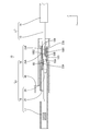
- FIG. 1 is a side view showing an electric wire with a terminal according to the first embodiment.
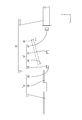
- FIG. 2 is a side sectional view showing an electric wire with a terminal.
- FIG. 3 is a perspective view showing the terminal body.
- FIG. 4 is a perspective view showing the terminal body.
- FIG. 5 is a side view showing a step of pushing the slide portion arranged at the temporarily locked position with respect to the terminal body forward with a jig.
- FIG. 6 is a diagram illustrating a state before the first fitting portion and the second fitting portion of the terminal body are unevenly fitted.
- FIG. 7 is a diagram illustrating a state after the first fitting portion and the second fitting portion of the terminal body are unevenly fitted.
- FIG. 1 is a side view showing an electric wire with a terminal according to the first embodiment.
- FIG. 2 is a side sectional view showing an electric wire with a terminal.
- FIG. 3 is a perspective view showing the terminal body.
- FIG. 4 is a perspective view showing the terminal body
- FIG. 8 is a diagram illustrating a state before the first fitting portion and the second fitting portion are unevenly fitted in the terminal body according to the second embodiment.
- FIG. 9 is a diagram illustrating a state after the first fitting portion and the second fitting portion of the terminal body are unevenly fitted.
- FIG. 10 is a diagram illustrating a state before the first fitting portion and the second fitting portion are unevenly fitted in the terminal body according to the third embodiment.
- FIG. 11 is a diagram illustrating a state after the first fitting portion and the second fitting portion of the terminal body are unevenly fitted.
- the present disclosure is a terminal connected to a front end portion in the extending direction of an electric wire, with respect to a terminal body having a holding portion for sandwiching the electric wire and the terminal body along the extending direction of the electric wire.
- the slide portion is provided with a slide portion that can be slid, and the slide portion has a pressurizing portion that pressurizes the holding portion toward the electric wire, and the terminal body is formed of a bent metal plate material.
- the holding portion has a holding protrusion that protrudes toward the electric wire and comes into contact with the electric wire, and the holding protrusion is formed by folding back the tip of the holding portion and overlapping the tip with the overlapping portion of the holding portion.
- the first facing surface of the overlapping portion and the second facing surface of the tip portion face each other and overlap each other, and the first fitting portion provided on the first facing surface and the second facing surface are opposed to each other.
- the second fitting portion provided on the surface is unevenly fitted.
- the holding protrusion can be combined with the second fitting portion of the holding protrusion.
- the first fitting portion of the sandwiching portion in an uneven manner, it is possible to prevent the holding protrusions formed by folding from turning over. As a result, the connection reliability between the terminal and the electric wire can be improved.
- the tip portion of the sandwiching portion has a contact surface that contacts the electric wire on a surface opposite to the second facing surface, and a recess is formed in the contact surface, and the tip portion Of these, the portion corresponding to the recess is preferably formed with the second fitting portion protruding from the second facing surface.
- the recess will function as a serration. That is, the pressure is concentrated on the contact portion between the opening edge of the recess and the core wire of the electric wire, and the oxide film formed on the surface of the core wire can be easily destroyed. As a result, the reliability of the electrical connection between the electric wire and the holding protrusion is improved.
- a structure protruding from the second facing surface may be formed. By using this protruding structure as the second fitting portion, the second fitting portion can be efficiently formed. This can contribute to the cost reduction of the terminal.
- the tip portion of the sandwiching portion has a contact surface that contacts the electric wire on a surface opposite to the second facing surface, and the tip portion has the contact surface and the second facing surface.
- a through hole is provided to penetrate the through hole, the opening on the second facing surface side in the through hole is the second fitting portion, and the first fitting portion corresponds to the second fitting portion. It is preferable that the position protrudes from the first facing surface toward the second fitting portion.
- the opening on the contact surface side of the through hole fulfills the function of serration, and the reliability of the electrical connection between the electric wire and the holding protrusion can be improved. Further, by using the opening on the second facing surface side of the through hole as the second fitting portion, the second fitting portion can be efficiently formed. This can contribute to the cost reduction of the terminal.
- a plurality of the first fitting portion and the second fitting portion are provided at intervals in the extending direction of the electric wire.
- the locking of the second fitting portion to the first fitting portion can be further strengthened.
- the terminal-equipped electric wire according to the present disclosure includes the terminal according to any one of (1) to (4) above and the electric wire connected to the terminal.
- Embodiment 1 of the present disclosure will be described with reference to FIGS. 1 to 7.
- the electric wire 10 with a terminal according to the first embodiment includes an electric wire 11 and a terminal 12 connected to the electric wire 11.
- the direction indicated by the arrow Z will be upward in the vertical direction
- the direction indicated by the arrow Y will be forward in the front-rear direction
- the direction indicated by the arrow X will be left in the left-right direction.
- a plurality of the same members only some of the members may be coded, and the codes of other members may be omitted.
- the electric wires 11 are arranged so as to extend in the front-rear direction (an example of the extension direction).
- the outer circumference of the core wire 13 of the electric wire 11 is surrounded by an insulating coating 14 made of an insulating synthetic resin.
- the core wire 13 according to the first embodiment is made of one metal wire.
- the core wire 13 may be a stranded wire obtained by twisting a plurality of fine metal wires.
- any metal such as copper, copper alloy, aluminum, and aluminum alloy can be appropriately selected as needed.
- the core wire 13 according to the first embodiment is made of copper or a copper alloy.
- the terminal 12 includes a metal terminal body 15 and a slide portion 16 that can slide relative to the terminal body 15.
- Terminal body 15 The terminal body 15 is formed by pressing a metal plate material into a predetermined shape.
- any metal such as copper, copper alloy, aluminum, aluminum alloy, and stainless steel can be appropriately selected as needed.
- the terminal body 15 according to the first embodiment is made of copper or a copper alloy.
- a plating layer may be formed on the surface of the terminal body 15.
- any metal such as tin, nickel, and silver can be appropriately selected as required.
- the terminal body 15 according to the first embodiment is tin-plated.
- the terminal body 15 has a tubular portion 17 into which a mating terminal (not shown) can be inserted, and an electric wire connecting portion 20 located behind the tubular portion 17 and connected to the front end of the electric wire 11.
- the electric wire connecting portion 20 includes an upper holding portion 18A and a lower holding portion 18B extending rearward.
- the tubular portion 17 has a square tubular shape extending in the front-rear direction.
- the front end of the tubular portion 17 is open so that the mating terminal can be inserted.
- An elastic contact piece (not shown) is arranged inside the tubular portion 17.
- the tubular portion 17 and the mating terminal are electrically connected by elastically contacting the mating terminal inserted into the tubular portion 17 with the elastic contact piece.
- FIG. 3 a square tubular electric wire connecting portion 20 is provided behind the tubular portion 17.
- An upper holding portion 18A (an example of a holding portion) is provided at the rear end of the upper wall of the electric wire connecting portion 20 so as to extend rearward
- a lower holding portion is provided at the rear end of the lower wall of the electric wire connecting portion 20.
- 18B (an example of a holding portion) is provided so as to extend rearward.
- the upper holding portion 18A and the lower holding portion 18B have an elongated shape extending back and forth.
- the upper holding portion 18A and the lower holding portion 18B are formed to have substantially the same length dimension in the front-rear direction.
- the electric wire connecting portion 20 is formed with a left side wall 34 rising from the left side edge 30 of the upper holding portion 18A and the left side edge 32 of the lower holding portion 18B, and the right side edge 31 and the lower holding portion 18A of the upper holding portion 18A.
- a right side wall 35 rising from the right side edge 33 of the portion 18B is formed.
- the lower surface of the upper holding portion 18A is provided with an upper holding protrusion 23A protruding downward at a position in front of the rear end portion.
- the upper holding protrusion 23A is formed in a state in which a portion of the upper holding portion 18A protruding from the left side edge 30 is in close contact with the lower surface of the upper holding portion 18A and folded.
- the right end portion of the upper holding portion 18A is formed so as not to project to the right from the right edge 31 of the upper holding portion 18A.
- the lower surface of the upper holding protrusion 23A is an upper contact surface 68 that contacts the core wire 13 of the electric wire 11.
- a lower holding protrusion 23B that projects upward is provided at the rear end of the upper surface of the lower holding portion 18B.
- the tip portion 18B2 protruding rearward from the rear end portion of the lower holding portion 18B is folded back and becomes an overlapping portion 18B1 of the lower holding portion 18B. It is formed by being stacked so as to be in close contact with each other.
- the first facing surface 60, which is the lower surface of the overlapping portion 18B1, and the second facing surface 61, which is the upper surface of the tip portion 18B2 (that is, the lower holding protrusion 23B) face each other and overlap each other.
- the region of the lower holding portion 18B where the lower holding protrusion 23B is provided is reinforced by the lower holding protrusion 23B to prevent bending.
- the upper surface of the lower holding protrusion 23B is a lower contact surface (contact surface) 64 that contacts the core wire 13 of the electric wire 11.
- Two recesses 66 are formed on the lower contact surface 64 of the lower holding protrusion 23B.
- the recess 66 has a shape recessed from the lower contact surface 64 of the lower holding protrusion 23B.
- the two recesses 66 are arranged so as to be spaced apart from each other in the front-rear direction.
- the lower holding protrusion 23B and the upper holding protrusion 23A are provided at positions shifted in the front-rear direction.
- the rear end portion of the upper holding protrusion 23A and the front end portion of the lower holding protrusion 23B are formed so as to be slightly separated in the front-rear direction.
- the distance between the rear end of the upper holding protrusion 23A and the front end of the lower holding protrusion 23B is set to be smaller than the diameter of the core wire 13.
- the core wire 13 and the terminal body 15 are electrically connected by contacting the metal surface with the upper holding portion 18A and the lower holding portion 18B.
- the upper contact surface 68 of the upper holding protrusion 23A and the lower contact surface 64 of the lower holding protrusion 23B bite into the oxide film formed on the surface of the core wire 13 to peel off the oxide film, whereby the core wire 13 is peeled off. It is designed to expose the metal surface of the cable.
- the recess 66 formed on the lower contact surface 64 side has a serration function of concentrating pressure on the contact portion between the opening edge of the recess 66 and the core wire 13. As a result, the oxide film formed on the surface of the core wire 13 can be easily broken.
- the core wire 13 and the terminal body 15 are electrically connected by contacting the metal surface with the upper holding protrusion 23A and the lower holding protrusion 23B.
- edge 50A formed at the rear end of the upper holding protrusion 23A and the edge 50B formed at the front end of the lower holding protrusion 23B are formed on the surface of the core wire 13 by biting into the core wire 13.
- the oxide film that has been removed is peeled off.
- the electrical connection between the core wire 13 and the terminal body 15 is made more reliable.
- a left easy bending portion 51 cut out to the right from the left edge 32 of the lower holding portion 18B is provided (see FIG. 3), and the lower holding portion 18B A right easy bending portion 52 cut out to the left from the right edge 33 is provided (see FIG. 4).
- the left easy bending portion 51 and the right easy bending portion 52 are provided at the same positions in the front-rear direction.
- the portion provided with the left easy bending portion 51 and the right easy bending portion 52 is formed to be narrower in the left-right direction than the other portions. As a result, the lower sandwiching portion 18B is bent so as to start from the left easy bending portion 51 and the right easy bending strong portion.
- First fitting portion 62, second fitting portion 63 As shown in FIG. 7, the first facing surface 60 is provided with two first fitting portions 62. The two first fitting portions 62 are arranged at intervals in the front-rear direction. Two second fitting portions 63 are provided on the second facing surface 61. The second fitting portions 63 are arranged at intervals in the front-rear direction. The second fitting portion 63 is fitted to the first fitting portion 62.
- the second fitting portion 63 has a shape protruding downward from the second facing surface 61.
- the second fitting portion 63 is secondarily formed with the formation of the recess 66. That is, the recess 66 is formed by a part of the lower holding protrusion 23B being pushed downward from the lower contact surface 64 side. With the formation of the recess 66, a part of the lower holding protrusion 23B is pushed downward from the second facing surface 61 side. As a result, two second fitting portions 63 are formed. Therefore, each second fitting portion 63 is formed at a position corresponding to each recess 66 in the vertical direction. In this way, by using the portion formed secondary to the formation of the recess 66 as the second fitting portion 63, it is more efficient than the case where the second fitting portion is newly formed.
- the second fitting portion 63 can be formed.
- the first fitting portion 62 is formed with an opening at a position corresponding to the second fitting portion 63 on the first facing surface 60.
- the first fitting portion 62 has a shape recessed from the first facing surface 60 of the lower holding portion 18B.
- the second fitting portion 63 of the lower holding protrusion 23B is inserted into the first fitting portion 62 of the lower holding portion 18B. Will be done.
- the first fitting portion 62 and the second fitting portion 63 are unevenly fitted, and the lower holding protrusion 23B is locked to the lower holding portion 18B.
- the slide portion 16 has a square tubular shape extending in the front-rear direction.
- the slide portion 16 is formed into a predetermined shape by a known method such as pressing, cutting, casting, or the like.
- any metal such as copper, copper alloy, aluminum, aluminum alloy, and stainless steel can be appropriately selected as needed.
- the slide portion 16 according to the first embodiment is not particularly limited, but is made of stainless steel.
- a plating layer may be formed on the surface of the slide portion 16.
- any metal such as tin, nickel, and silver can be appropriately selected as required.
- a jig contact portion 46 projecting upward is formed at the front end portion of the upper wall of the slide portion 16.
- a jig 45 which will be described later, comes into contact with the jig contact portion 46 from the rear (see FIG. 5).
- an upper pressurizing portion 25A projecting downward is provided on the lower surface of the upper wall of the slide portion 16.
- a lower pressurizing portion 25B projecting upward is provided on the upper surface of the lower wall of the slide portion 16.
- Inclined surfaces are formed on the front surface of the upper pressurizing portion 25A and the front surface of the lower pressurizing portion 25B.
- a temporary locking receiving portion 26 is opened on the side wall of the slide portion 16 at a position closer to the front end portion in the front-rear direction. Further, on the side wall of the slide portion 16, the main locking receiving portion 27 is opened at a position behind the temporary locking receiving portion 26.
- the temporary locking receiving portion 26 and the main locking receiving portion 27 can be elastically locked to the locking projections 28 provided on the left side wall 34 and the right side wall 35 of the terminal body 15.
- the state in which the locking projection 28 of the terminal body 15 and the temporary locking receiving portion 26 of the slide portion 16 are locked is a state in which the slide portion 16 is held at the temporary locking position with respect to the terminal main body 15. (See FIG. 1).
- the upper pressurizing portion 25A and the lower pressurizing portion 25B of the slide portion 16 are separated rearward from the rear end edges of the upper holding portion 18A and the lower holding portion 18B of the terminal body 15. Further, in this state, the distance between the upper holding portion 18A and the lower holding portion 18B is set to be larger than the diameter of the core wire 13.
- the slide portion 16 is locked at the main locking position with respect to the terminal main body 15. (See Fig. 5).
- the upper pressurizing portion 25A of the slide portion 16 is in contact with the upper holding portion 18A from above the upper holding portion 18A.
- the lower pressurizing portion 25B of the slide portion 16 is in contact with the lower holding portion 18B from below the lower holding portion 18B.
- the slide portion 16 is fitted into the region of the terminal body 15 where the upper holding portion 18A and the lower holding portion 18B are provided, and is fitted into the above-mentioned temporary locking position and the main locking. It is possible to slide between the position and the front-back direction (the extending direction of the electric wire).
- the upper holding portion 18A is pressed by the upper pressing portion 25A from above to press the upper holding portion 18A. Is designed to bend downward. Further, the lower pressing portion 25B presses the lower holding portion 18B from below, so that the lower holding portion 18B bends upward.
- the core wire 13 is arranged in the space between the upper holding portion 18A and the lower holding portion 18B in a state of being extended in the front-rear direction (extending direction), and the slide portion 16 is arranged with respect to the terminal body 15.
- the core wire 13 is sandwiched from above and below by the bent upper holding portion 18A and the lower holding portion 18B. That is, the upper holding portion 18A comes into contact with the core wire 13 from above by being pressed downward by the upper pressing portion 25A, and the lower holding portion 18B is pressed upward by the lower pressing portion 25B to bring the core wire 13 into contact. It comes in contact with the cable from below.
- the upper holding protrusion 23A of the upper holding portion 18A presses the core wire 13 from above, and the lower side.
- the lower holding protrusion 23B of the holding portion 18B presses the core wire 13 from below.
- the core wire 13 is pressed from above by the upper holding protrusion 23A and is pressed from below by the lower holding protrusion 23B arranged at a position deviated from the upper holding protrusion 23A in the front-rear direction. Therefore, it is held in a bent state in the vertical direction.
- the core wire 13 is held by the upper holding protrusion 23A and the lower holding protrusion 23B in a state of being bent like a crank when viewed from the side. Further, the core wire 13 and the terminal 12 are also electrically connected by the upper holding protrusion 23A and the lower holding protrusion 23B.
- a jig contact portion 46 is formed at the front end portion of the upper wall of the slide portion 16.
- the jig 45 comes into contact with the jig contact portion 46 from the rear, and the slide portion 16 is pushed forward by the jig 45, so that the slide portion 16 can move forward.
- the jig 45 is relatively small in size as compared with a mold and equipment for operating the mold. Therefore, the increase in cost caused by the jig 45 is suppressed.
- a pair of invitation portions 47 projecting inward of the slide portion 16 are provided on the left and right side walls at a position near the rear end portion of the slide portion 16.
- the invitation portion 47 is formed narrower from the rear to the front.
- the lower holding protrusion 23B slides with the core wire 13 of the electric wire 11 when the electric wire 11 is pulled backward, and is displaced in the extending direction of the electric wire 11. Even if it is attempted, the lower holding protrusion 63 formed by folding the second fitting portion 63 of the lower holding protrusion 23B and the first fitting portion 62 of the lower holding portion 18B are folded and formed. It is possible to prevent the 23B from turning over. As a result, the connection reliability between the terminal 12 and the electric wire 11 can be improved.
- the recess 66 fulfills the function of serration. That is, the pressure is concentrated on the contact portion between the opening edge of the recess 66 and the core wire 13 of the electric wire 11, and the oxide film formed on the surface of the core wire 13 can be easily destroyed. As a result, the reliability of the electrical connection between the electric wire 11 and the lower holding protrusion 23B is improved.
- the recess 66 is formed in a recessed shape from the lower contact surface 64, a structure protruding from the second facing surface 61 may be formed. By using this protruding structure as the second fitting portion 63, the second fitting portion 63 can be efficiently formed. This can contribute to cost reduction of the terminal 12.
- the second fitting portion 63 can be attached to the first fitting portion 62.
- the locking can be made stronger.
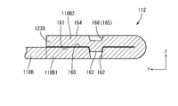
- the lower holding protrusion 123B at the terminal 112 is formed by folding back the tip 118B2 of the lower holding portion 118B and stacking the lower holding protrusion 123B so as to be in close contact with the overlapping portion 118B1 of the lower holding portion 118B.
- a recess 166 is formed in the lower holding protrusion 123B of the terminal 112.
- One recess 166 is provided on the lower contact surface 164 side, and has a serration function as in the recess 66 of the first embodiment.
- one second fitting portion 163 on the second facing surface 161 side is provided at a position corresponding to the recess 166.
- the first fitting portion 162 in the lower holding portion 118B is provided at a position corresponding to the second fitting portion 163, and is formed by penetrating the first facing surface 160 and the lower surface of the lower holding portion 118B. Has been done. When the lower holding protrusion 123B is folded over the lower holding portion 118B, the first fitting portion 162 and the second fitting portion 163 are unevenly fitted.
- the terminal is compared with a configuration in which the first fitting portion 62 is recessed from the first facing surface 60 as in the first embodiment, for example.
- the weight of 112 is reduced.
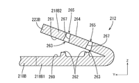
- the lower holding protrusion 123B at the terminal 212 is formed by folding back the tip portion 218B2 of the lower holding portion 218B and overlapping the lower holding portion 218B so as to be in close contact with the overlapping portion 218B1.
- the lower holding protrusion 223B of the terminal 212 is formed with a through hole 267 that penetrates the lower contact surface 264 and the second facing surface 261. Two through holes 267 are provided at intervals in the front-rear direction.
- the opening on the lower contact surface 264 side of the through hole 267 has a serration function. Further, the opening on the second facing surface 261 side in the through hole 267 is a second fitting portion 263.
- the first fitting portion 262 has a shape that protrudes upward from the first facing surface 260.
- the first fitting portion 262 is formed, for example, by welding on the first facing surface 260 or cutting the surface on the first facing surface 260 side.
- the first fitting portion 262 is provided at a position corresponding to the second fitting portion 263.
- the first fitting portion 262 is inserted into the opening of the second fitting portion 263.
- the first fitting portion 262 and the second fitting portion 263 are unevenly fitted.
- the opening on the lower contact surface 264 side of the through hole 267 serves the function of serration, and is shown in the third embodiment because the electric wire 11 (the electric wire 11 has the same configuration as that of the first embodiment).
- the reliability of the electrical connection between the lower holding protrusion 223B and the lower holding protrusion 223B can be improved.
- the second fitting portion 263 can be efficiently formed. This can contribute to cost reduction of the terminal 212.
- the configuration is such that two recesses 66 are provided, and in the second embodiment, the configuration is such that one recess 166 is provided, but the present invention is not limited to this.
- three or more recesses may be provided.
- the second fitting portion and the first fitting portion may also have a configuration of three or more according to the number of recesses.
- the lower holding protrusions 23B and 123B of the terminals 12 and 112 are provided with recesses 66 and 166 having a serration function, but the present invention is limited to this. It may be configured so that the lower holding protrusion is not provided with a recess.
- the first fitting portions 62, 162, 262 and the second fitting portions 63, 163, 263 are provided on the lower holding portions 18B, 118B, 218B side.
- the first fitting portion and the second fitting portion may be provided on the upper holding portion side.
- the lower holding protrusion 23B is in a state in which a portion protruding rearward from the rear end portion of the lower holding portion 18B is in close contact with the upper surface of the lower holding portion 18B and folded. The configuration is formed, but it is not limited to this.
- the lower holding protrusion is formed in a state in which a portion of the lower holding portion that protrudes laterally from one of the left and right side edges of the lower holding portion is in close contact with the upper surface of the lower holding portion and folded. It may be configured as such.
- the first fitting portion 262 is formed by welding on the first facing surface 260 or cutting the surface on the first facing surface 260 side. It is not limited to.
- the first fitting portion may be formed by knocking out the lower holding portion from the lower surface side. In this case, a recess is formed on the lower surface side of the lower holding portion.
Landscapes
- Connections Effected By Soldering, Adhesion, Or Permanent Deformation (AREA)
Abstract
Provided is a terminal 12 connected to an extending-direction front end of an electric wire 11, said terminal comprising a terminal body 15 having a grip section for gripping the electric wire 11 and a slide section 16 slidable with respect to the terminal body 15 along the extending direction of the electric wire 11. The slide section 16 has a press part for pressing the grip section toward the electric wire 11. The terminal body 15 is formed from a folded metal plate material. The grip section has a holding protrusion part which protrudes toward the electric wire 11 so as to be in contact with the electric wire 11 and which is formed by folding a leading-end part of the grip section such that the leading-end part overlaps with an overlap part 18B1 of the grip section. A first facing surface 60 of the overlap part 18B1 and a second facing surface 61 of the leading-end part overlap face-to-face with each other, with a first fitting part 62 provided on the first facing surface 60 and a second fitting part 63 provided on the second facing surface 61 being fitted together in an interdigitating manner.
Description
本開示は、端子、および端子付き電線に関する。
This disclosure relates to terminals and electric wires with terminals.
従来より、電線の端末から露出する芯線に端子が接続された端子付き電線が知られている。このような端子として、例えば、電線の端末から露出する芯線に外側から圧着する圧着部を備えるものがある。
Conventionally, an electric wire with a terminal has been known in which a terminal is connected to a core wire exposed from the terminal of the electric wire. As such a terminal, for example, there is one provided with a crimping portion for crimping from the outside to a core wire exposed from the end of the electric wire.
上記の端子を電線に圧着するには、例えば以下のようにする。まず、金属板材をプレス加工することにより所定の形状の端子を成形する。続いて、上下方向に相対移動可能な一対の金型のうち下側に位置する下型の載置部に、端子を載置する。続いて、電線の端末から露出された芯線を、端子の圧着部に重ねて載置する。その後、一対の金型の一方又は双方を互いに接近する方向に移動させ、上型の圧着部と、下型の載置部との間で圧着部を挟み付けることにより、圧着部を電線の芯線に圧着する。以上により、電線の端末に端子が接続される(特許文献1参照)。
To crimp the above terminal to the electric wire, for example, do as follows. First, a terminal having a predetermined shape is formed by pressing a metal plate material. Subsequently, the terminals are mounted on the mounting portion of the lower mold located on the lower side of the pair of molds that can move relative to each other in the vertical direction. Subsequently, the core wire exposed from the terminal of the electric wire is placed on the crimping portion of the terminal. After that, one or both of the pair of dies are moved in a direction close to each other, and the crimping portion is sandwiched between the crimping portion of the upper mold and the mounting portion of the lower mold, so that the crimping portion is the core wire of the electric wire. Crimping to. As described above, the terminal is connected to the terminal of the electric wire (see Patent Document 1).
しかしながら上記の技術によれば、電線の芯線に端子の圧着部を圧着するための金型や治具等、比較的に大規模な設備が必要なので、設備投資が必要となり、製造コストが上昇するという問題がある。
上記の問題を解決するために、以下の端子が考えられる。端子は、電線の延び方向に沿って変形可能な挟持部を備えた端子本体と、電線の延び方向に沿って端子本体に対して移動可能なスライド部と、を備える。スライド部は、電線が挟持部に配された状態で、挟持部を前記電線に押圧する加圧部を有する。 However, according to the above technology, relatively large-scale equipment such as a mold and a jig for crimping the crimping portion of the terminal to the core wire of the electric wire is required, which requires capital investment and increases the manufacturing cost. There is a problem.
In order to solve the above problem, the following terminals can be considered. The terminal includes a terminal body having a holding portion that can be deformed along the extending direction of the electric wire, and a sliding portion that can move with respect to the terminal body along the extending direction of the electric wire. The slide portion has a pressurizing portion that presses the sandwiched portion against the electric wire in a state where the electric wire is arranged on the sandwiching portion.
このような端子における端子本体の挟持部には、仮想的な技術として、挟持部の側縁から突出した部分が挟持部に折り重ねられることにより形成された保持突部を設けることが考えられる。保持突部は挟持部から電線に向けて突出している。電線は保持突部によって押さえられ、挟持部に保持される。
As a virtual technique, it is conceivable to provide a holding protrusion formed by folding a portion protruding from the side edge of the holding portion onto the holding portion in the holding portion of the terminal body in such a terminal. The holding protrusion protrudes from the holding portion toward the electric wire. The electric wire is held by the holding protrusion and is held by the holding portion.
例えば、電線が引っ張られることによって保持突部が電線と摺動し、保持突部が電線の延び方向の後方に力を受けると、折り重ねられた保持突部がめくれるおそれがあり、この場合、端子と電線との電気的な接続信頼性が低下することが懸念される。
For example, if the holding protrusion slides with the electric wire due to the electric wire being pulled and the holding protrusion receives a force rearward in the extending direction of the electric wire, the folded holding protrusion may be turned over. There is a concern that the reliability of the electrical connection between the terminal and the electric wire will decrease.
本明細書に開示された技術は上記のような事情に基づいて完成されたものであって、端子と電線との接続信頼性を向上する端子を提供することを目的とする。
The technology disclosed in this specification has been completed based on the above circumstances, and an object thereof is to provide a terminal for improving the connection reliability between the terminal and the electric wire.
本開示は、電線の延び方向の前方端部に接続される端子であって、前記電線を挟持する挟持部を有する端子本体と、前記電線の延び方向に沿って前記端子本体に対してスライド可能なスライド部と、を備え、前記スライド部は前記挟持部を前記電線に向けて加圧する加圧部を有し、前記端子本体は折れ曲がった状態の金属板材により形成されており、前記挟持部は前記電線に向かって突出し前記電線に接触する保持突部を有し、前記保持突部は前記挟持部の先端部を折り返して、前記挟持部の重なり部に前記先端部が重なって形成されており、前記重なり部の第1対向面と前記先端部の第2対向面とが対向して重なっており、前記第1対向面に設けられた第1嵌合部と、前記第2対向面に設けられた第2嵌合部とが凹凸嵌合する。
The present disclosure is a terminal connected to a front end portion in an extension direction of an electric wire, and is slidable with respect to a terminal body having a holding portion for sandwiching the electric wire and the terminal body along the extension direction of the electric wire. The slide portion has a pressurizing portion that pressurizes the sandwiching portion toward the electric wire, and the terminal body is formed of a metal plate material in a bent state. It has a holding protrusion that protrudes toward the electric wire and comes into contact with the electric wire, and the holding protrusion is formed by folding back the tip of the holding portion and overlapping the tip with the overlapping portion of the holding portion. The first facing surface of the overlapping portion and the second facing surface of the tip portion face each other and overlap each other, and are provided on the first mating portion provided on the first facing surface and the second facing surface. The second fitting portion and the formed second fitting portion are unevenly fitted.
本開示によれば、端子と電線との接続信頼性を向上できる。
According to the present disclosure, the connection reliability between the terminal and the electric wire can be improved.
[本開示の実施形態の説明]
最初に本開示の実施態様が列挙されて説明される。 [Explanation of Embodiments of the present disclosure]
First, embodiments of the present disclosure will be listed and described.
最初に本開示の実施態様が列挙されて説明される。 [Explanation of Embodiments of the present disclosure]
First, embodiments of the present disclosure will be listed and described.
(1)本開示は、電線の延び方向の前方端部に接続される端子であって、前記電線を挟持する挟持部を有する端子本体と、前記電線の延び方向に沿って前記端子本体に対してスライド可能なスライド部と、を備え、前記スライド部は前記挟持部を前記電線に向けて加圧する加圧部を有し、前記端子本体は折れ曲がった状態の金属板材により形成されており、前記挟持部は前記電線に向かって突出し前記電線に接触する保持突部を有し、前記保持突部は前記挟持部の先端部を折り返して、前記挟持部の重なり部に前記先端部が重なって形成されており、前記重なり部の第1対向面と前記先端部の第2対向面とが対向して重なっており、前記第1対向面に設けられた第1嵌合部と、前記第2対向面に設けられた第2嵌合部とが凹凸嵌合する。
(1) The present disclosure is a terminal connected to a front end portion in the extending direction of an electric wire, with respect to a terminal body having a holding portion for sandwiching the electric wire and the terminal body along the extending direction of the electric wire. The slide portion is provided with a slide portion that can be slid, and the slide portion has a pressurizing portion that pressurizes the holding portion toward the electric wire, and the terminal body is formed of a bent metal plate material. The holding portion has a holding protrusion that protrudes toward the electric wire and comes into contact with the electric wire, and the holding protrusion is formed by folding back the tip of the holding portion and overlapping the tip with the overlapping portion of the holding portion. The first facing surface of the overlapping portion and the second facing surface of the tip portion face each other and overlap each other, and the first fitting portion provided on the first facing surface and the second facing surface are opposed to each other. The second fitting portion provided on the surface is unevenly fitted.
上記構成とすることで、保持突部が、例えば電線が引っ張られた際に保持突部が電線と摺動し、電線の延び方向に変位しようとしても、保持突部の第2嵌合部と挟持部の第1嵌合部とが凹凸嵌合することにより、折り重ねて形成された保持突部がめくれることを抑制できる。これにより、端子と電線との接続信頼性を向上できる。
With the above configuration, even if the holding protrusion slides with the electric wire when the electric wire is pulled and tries to be displaced in the extending direction of the electric wire, the holding protrusion can be combined with the second fitting portion of the holding protrusion. By fitting the first fitting portion of the sandwiching portion in an uneven manner, it is possible to prevent the holding protrusions formed by folding from turning over. As a result, the connection reliability between the terminal and the electric wire can be improved.
(2)前記挟持部の前記先端部は、前記第2対向面と反対側の面に、前記電線に接触する接触面を有し、前記接触面には凹部が形成されており、前記先端部のうち前記凹部に対応する部分は前記第2対向面から突出する前記第2嵌合部が形成されていることが好ましい。
(2) The tip portion of the sandwiching portion has a contact surface that contacts the electric wire on a surface opposite to the second facing surface, and a recess is formed in the contact surface, and the tip portion Of these, the portion corresponding to the recess is preferably formed with the second fitting portion protruding from the second facing surface.
接触面に凹部を形成することにより、凹部はセレーションの機能を果たすこととなる。すなわち、凹部の開口縁と電線の芯線との接触部分に圧力が集中され、芯線の表面に形成された酸化被膜を容易に破壊できる。これにより、電線と保持突部との電気的な接続信頼性が向上する。この凹部を形成する際に、第2対向面から突出する構造が形成される場合がある。この突出構造を第2嵌合部とすることで、効率的に第2嵌合部を形成できる。これにより、端子のコスト低減に寄与できる。
By forming a recess on the contact surface, the recess will function as a serration. That is, the pressure is concentrated on the contact portion between the opening edge of the recess and the core wire of the electric wire, and the oxide film formed on the surface of the core wire can be easily destroyed. As a result, the reliability of the electrical connection between the electric wire and the holding protrusion is improved. When forming this recess, a structure protruding from the second facing surface may be formed. By using this protruding structure as the second fitting portion, the second fitting portion can be efficiently formed. This can contribute to the cost reduction of the terminal.
(3)前記挟持部の前記先端部は、前記第2対向面と反対側の面に、前記電線に接触する接触面を有し、前記先端部には、前記接触面と前記第2対向面とを貫通する貫通孔が設けられており、前記貫通孔における前記第2対向面側の開口は前記第2嵌合部とされ、前記第1嵌合部は、前記第2嵌合部に対応する位置に、前記第1対向面から前記第2嵌合部に向けて突出する形状をなしていることが好ましい。
(3) The tip portion of the sandwiching portion has a contact surface that contacts the electric wire on a surface opposite to the second facing surface, and the tip portion has the contact surface and the second facing surface. A through hole is provided to penetrate the through hole, the opening on the second facing surface side in the through hole is the second fitting portion, and the first fitting portion corresponds to the second fitting portion. It is preferable that the position protrudes from the first facing surface toward the second fitting portion.
貫通孔の接触面側の開口は、セレーションの機能を果たすこととなり、電線と保持突部との電気的な接続信頼性を向上できる。また、貫通孔における第2対向面側の開口を第2嵌合部とすることで、効率的に第2嵌合部を形成できる。これにより、端子のコスト低減に寄与できる。
The opening on the contact surface side of the through hole fulfills the function of serration, and the reliability of the electrical connection between the electric wire and the holding protrusion can be improved. Further, by using the opening on the second facing surface side of the through hole as the second fitting portion, the second fitting portion can be efficiently formed. This can contribute to the cost reduction of the terminal.
(4)前記第1嵌合部および前記第2嵌合部は、前記電線の延び方向に間隔をあけて複数設けられていることが好ましい。
(4) It is preferable that a plurality of the first fitting portion and the second fitting portion are provided at intervals in the extending direction of the electric wire.
第1嵌合部および第2嵌合部を電線の延び方向に複数設けることで、第2嵌合部の第1嵌合部への係止をより強固なものにできる。
By providing a plurality of first fitting portions and second fitting portions in the extending direction of the electric wire, the locking of the second fitting portion to the first fitting portion can be further strengthened.
(5)本開示にかかる端子付き電線は、上記(1)から(4)のいずれか1つに記載の端子と、前記端子に接続される電線と、を備える。
(5) The terminal-equipped electric wire according to the present disclosure includes the terminal according to any one of (1) to (4) above and the electric wire connected to the terminal.
[本開示の実施形態の詳細]
以下に、本開示の実施形態が説明される。本発明はこれらの例示に限定されるものではなく、特許請求の範囲によって示され、特許請求の範囲と均等の意味および範囲内での全ての変更が含まれることが意図される。 [Details of Embodiments of the present disclosure]
The embodiments of the present disclosure will be described below. The present invention is not limited to these examples, and is indicated by the scope of claims, and is intended to include all modifications within the meaning and scope equivalent to the scope of claims.
<実施形態1>
本開示の実施形態1が図1から図7を参照しつつ説明される。実施形態1にかかる端子付き電線10は、電線11と、電線11に接続される端子12とを備える。以下の説明では、矢線Zの示す向きを上下方向における上方とし、矢線Yの示す向きを前後方向における前方とし、矢線Xの示す向きを左右方向における左方として説明する。なお、複数の同一部材については、一部の部材にのみ符号を付し、他の部材の符号を省略する場合がある。 <Embodiment 1>
Embodiment 1 of the present disclosure will be described with reference to FIGS. 1 to 7. Theelectric wire 10 with a terminal according to the first embodiment includes an electric wire 11 and a terminal 12 connected to the electric wire 11. In the following description, the direction indicated by the arrow Z will be upward in the vertical direction, the direction indicated by the arrow Y will be forward in the front-rear direction, and the direction indicated by the arrow X will be left in the left-right direction. Regarding a plurality of the same members, only some of the members may be coded, and the codes of other members may be omitted.
本開示の実施形態1が図1から図7を参照しつつ説明される。実施形態1にかかる端子付き電線10は、電線11と、電線11に接続される端子12とを備える。以下の説明では、矢線Zの示す向きを上下方向における上方とし、矢線Yの示す向きを前後方向における前方とし、矢線Xの示す向きを左右方向における左方として説明する。なお、複数の同一部材については、一部の部材にのみ符号を付し、他の部材の符号を省略する場合がある。 <Embodiment 1>
Embodiment 1 of the present disclosure will be described with reference to FIGS. 1 to 7. The
[電線11]
図1に示されるように、電線11は、前後方向(延び方向の一例)に延びて配されている。電線11は、芯線13の外周を絶縁性の合成樹脂からなる絶縁被覆14で包囲されている。実施形態1にかかる芯線13は、1本の金属線からなる。なお、芯線13は複数の金属細線が撚り合わされてなる撚線であってもよい。芯線13を構成する金属は、銅、銅合金、アルミニウム、アルミニウム合金等、必要に応じて任意の金属を適宜に選択できる。実施形態1にかかる芯線13は銅、または銅合金からなる。 [Electric wire 11]
As shown in FIG. 1, theelectric wires 11 are arranged so as to extend in the front-rear direction (an example of the extension direction). The outer circumference of the core wire 13 of the electric wire 11 is surrounded by an insulating coating 14 made of an insulating synthetic resin. The core wire 13 according to the first embodiment is made of one metal wire. The core wire 13 may be a stranded wire obtained by twisting a plurality of fine metal wires. As the metal constituting the core wire 13, any metal such as copper, copper alloy, aluminum, and aluminum alloy can be appropriately selected as needed. The core wire 13 according to the first embodiment is made of copper or a copper alloy.
図1に示されるように、電線11は、前後方向(延び方向の一例)に延びて配されている。電線11は、芯線13の外周を絶縁性の合成樹脂からなる絶縁被覆14で包囲されている。実施形態1にかかる芯線13は、1本の金属線からなる。なお、芯線13は複数の金属細線が撚り合わされてなる撚線であってもよい。芯線13を構成する金属は、銅、銅合金、アルミニウム、アルミニウム合金等、必要に応じて任意の金属を適宜に選択できる。実施形態1にかかる芯線13は銅、または銅合金からなる。 [Electric wire 11]
As shown in FIG. 1, the
[端子12]
図1に示されるように、端子12は、金属製の端子本体15と、端子本体15に対して相対的にスライド移動可能なスライド部16と、を備える。 [Terminal 12]
As shown in FIG. 1, the terminal 12 includes ametal terminal body 15 and a slide portion 16 that can slide relative to the terminal body 15.
図1に示されるように、端子12は、金属製の端子本体15と、端子本体15に対して相対的にスライド移動可能なスライド部16と、を備える。 [Terminal 12]
As shown in FIG. 1, the terminal 12 includes a
[端子本体15]
端子本体15は、金属板材を所定の形状にプレス加工することにより形成される。端子本体15を構成する金属は、銅、銅合金、アルミニウム、アルミニウム合金、ステンレス鋼等、必要に応じて任意の金属を適宜に選択できる。実施形態1にかかる端子本体15は、銅、又は銅合金からなる。端子本体15の表面にはめっき層が形成されていてもよい。めっき層を構成する金属は、スズ、ニッケル、銀等必要に応じて任意の金属を適宜に選択できる。実施形態1にかかる端子本体15にはスズめっきが施されている。 [Terminal body 15]
Theterminal body 15 is formed by pressing a metal plate material into a predetermined shape. As the metal constituting the terminal body 15, any metal such as copper, copper alloy, aluminum, aluminum alloy, and stainless steel can be appropriately selected as needed. The terminal body 15 according to the first embodiment is made of copper or a copper alloy. A plating layer may be formed on the surface of the terminal body 15. As the metal constituting the plating layer, any metal such as tin, nickel, and silver can be appropriately selected as required. The terminal body 15 according to the first embodiment is tin-plated.
端子本体15は、金属板材を所定の形状にプレス加工することにより形成される。端子本体15を構成する金属は、銅、銅合金、アルミニウム、アルミニウム合金、ステンレス鋼等、必要に応じて任意の金属を適宜に選択できる。実施形態1にかかる端子本体15は、銅、又は銅合金からなる。端子本体15の表面にはめっき層が形成されていてもよい。めっき層を構成する金属は、スズ、ニッケル、銀等必要に応じて任意の金属を適宜に選択できる。実施形態1にかかる端子本体15にはスズめっきが施されている。 [Terminal body 15]
The
図2に示されるように、端子本体15は、図示しない相手方端子が挿入可能な筒部17と、筒部17の後方に位置して電線11の前方端部と接続される電線接続部20を有する。電線接続部20は後方に延出された上側挟持部18Aおよび下側挟持部18Bと、を備える。
As shown in FIG. 2, the terminal body 15 has a tubular portion 17 into which a mating terminal (not shown) can be inserted, and an electric wire connecting portion 20 located behind the tubular portion 17 and connected to the front end of the electric wire 11. Have. The electric wire connecting portion 20 includes an upper holding portion 18A and a lower holding portion 18B extending rearward.
図2に示されるように、筒部17は前後方向に延びる角筒状をなしている。筒部17の前端は相手方端子が挿入可能に開口されている。筒部17の内部には、図示しない弾性接触片が配されている。筒部17内に挿入された相手方端子に、弾性接触片に弾性的に接触することにより、筒部17と相手方端子とが電気的に接続される。
As shown in FIG. 2, the tubular portion 17 has a square tubular shape extending in the front-rear direction. The front end of the tubular portion 17 is open so that the mating terminal can be inserted. An elastic contact piece (not shown) is arranged inside the tubular portion 17. The tubular portion 17 and the mating terminal are electrically connected by elastically contacting the mating terminal inserted into the tubular portion 17 with the elastic contact piece.
[上側挟持部18A、下側挟持部18B]
図3に示されるように、筒部17の後方には角筒状をなす電線接続部20が設けられている。電線接続部20の上壁の後端部には上側挟持部18A(挟持部の一例)が後方に延びて設けられており、電線接続部20の下壁の後端部には下側挟持部18B(挟持部の一例)が後方に延びて設けられている。上側挟持部18Aと下側挟持部18Bは前後に延びた細長い形状をなしている。上側挟持部18Aと下側挟持部18Bの前後方向の長さ寸法は略同じに形成されている。電線接続部20には、上側挟持部18Aの左側縁30および下側挟持部18Bの左側縁32から立ち上がる左側壁34が形成されており、また、上側挟持部18Aの右側縁31および下側挟持部18Bの右側縁33から立ち上がる右側壁35が形成されている。 [Upper holding portion 18A, lower holding portion 18B]
As shown in FIG. 3, a square tubular electricwire connecting portion 20 is provided behind the tubular portion 17. An upper holding portion 18A (an example of a holding portion) is provided at the rear end of the upper wall of the electric wire connecting portion 20 so as to extend rearward, and a lower holding portion is provided at the rear end of the lower wall of the electric wire connecting portion 20. 18B (an example of a holding portion) is provided so as to extend rearward. The upper holding portion 18A and the lower holding portion 18B have an elongated shape extending back and forth. The upper holding portion 18A and the lower holding portion 18B are formed to have substantially the same length dimension in the front-rear direction. The electric wire connecting portion 20 is formed with a left side wall 34 rising from the left side edge 30 of the upper holding portion 18A and the left side edge 32 of the lower holding portion 18B, and the right side edge 31 and the lower holding portion 18A of the upper holding portion 18A. A right side wall 35 rising from the right side edge 33 of the portion 18B is formed.
図3に示されるように、筒部17の後方には角筒状をなす電線接続部20が設けられている。電線接続部20の上壁の後端部には上側挟持部18A(挟持部の一例)が後方に延びて設けられており、電線接続部20の下壁の後端部には下側挟持部18B(挟持部の一例)が後方に延びて設けられている。上側挟持部18Aと下側挟持部18Bは前後に延びた細長い形状をなしている。上側挟持部18Aと下側挟持部18Bの前後方向の長さ寸法は略同じに形成されている。電線接続部20には、上側挟持部18Aの左側縁30および下側挟持部18Bの左側縁32から立ち上がる左側壁34が形成されており、また、上側挟持部18Aの右側縁31および下側挟持部18Bの右側縁33から立ち上がる右側壁35が形成されている。 [
As shown in FIG. 3, a square tubular electric
[上側保持突部23A]
図3に示されるように、上側挟持部18Aの下面には、後端部よりも前方の位置に、下方に突出する上側保持突部23Aが設けられている。上側保持突部23Aは、上側挟持部18Aの左側縁30から突出した部分が上側挟持部18Aの下面に密着して折り重ねられた状態で形成されている。上側挟持部18Aの右端部は、上側挟持部18Aの右側縁31から右方に突出しないように形成されている。図2に示すように、上側保持突部23Aの下面は、電線11の芯線13に接触する上側接触面68とされる。 [Upper holding protrusion 23A]
As shown in FIG. 3, the lower surface of theupper holding portion 18A is provided with an upper holding protrusion 23A protruding downward at a position in front of the rear end portion. The upper holding protrusion 23A is formed in a state in which a portion of the upper holding portion 18A protruding from the left side edge 30 is in close contact with the lower surface of the upper holding portion 18A and folded. The right end portion of the upper holding portion 18A is formed so as not to project to the right from the right edge 31 of the upper holding portion 18A. As shown in FIG. 2, the lower surface of the upper holding protrusion 23A is an upper contact surface 68 that contacts the core wire 13 of the electric wire 11.
図3に示されるように、上側挟持部18Aの下面には、後端部よりも前方の位置に、下方に突出する上側保持突部23Aが設けられている。上側保持突部23Aは、上側挟持部18Aの左側縁30から突出した部分が上側挟持部18Aの下面に密着して折り重ねられた状態で形成されている。上側挟持部18Aの右端部は、上側挟持部18Aの右側縁31から右方に突出しないように形成されている。図2に示すように、上側保持突部23Aの下面は、電線11の芯線13に接触する上側接触面68とされる。 [
As shown in FIG. 3, the lower surface of the
[下側保持突部23B]
図3に示されるように、下側挟持部18Bの上面の後端部には、上方に突出する下側保持突部23Bが設けられている。図6、図7に示されるように、下側保持突部23Bは、下側挟持部18Bの後端部から後方に突出した先端部18B2が折り返され、下側挟持部18Bの重なり部18B1に密着するように重ねられることで形成されている。重なり部18B1の下面である第1対向面60と、先端部18B2(すなわち、下側保持突部23B)の上面である第2対向面61とが対向して重なっている。下側挟持部18Bのうち下側保持突部23Bが設けられた領域は、下側保持突部23Bによって補強されることにより撓みにくくなっている。下側保持突部23Bの上面は、電線11の芯線13に接触する下側接触面(接触面)64とされる。 [Lower holdingprotrusion 23B]
As shown in FIG. 3, alower holding protrusion 23B that projects upward is provided at the rear end of the upper surface of the lower holding portion 18B. As shown in FIGS. 6 and 7, in the lower holding protrusion 23B, the tip portion 18B2 protruding rearward from the rear end portion of the lower holding portion 18B is folded back and becomes an overlapping portion 18B1 of the lower holding portion 18B. It is formed by being stacked so as to be in close contact with each other. The first facing surface 60, which is the lower surface of the overlapping portion 18B1, and the second facing surface 61, which is the upper surface of the tip portion 18B2 (that is, the lower holding protrusion 23B), face each other and overlap each other. The region of the lower holding portion 18B where the lower holding protrusion 23B is provided is reinforced by the lower holding protrusion 23B to prevent bending. The upper surface of the lower holding protrusion 23B is a lower contact surface (contact surface) 64 that contacts the core wire 13 of the electric wire 11.
図3に示されるように、下側挟持部18Bの上面の後端部には、上方に突出する下側保持突部23Bが設けられている。図6、図7に示されるように、下側保持突部23Bは、下側挟持部18Bの後端部から後方に突出した先端部18B2が折り返され、下側挟持部18Bの重なり部18B1に密着するように重ねられることで形成されている。重なり部18B1の下面である第1対向面60と、先端部18B2(すなわち、下側保持突部23B)の上面である第2対向面61とが対向して重なっている。下側挟持部18Bのうち下側保持突部23Bが設けられた領域は、下側保持突部23Bによって補強されることにより撓みにくくなっている。下側保持突部23Bの上面は、電線11の芯線13に接触する下側接触面(接触面)64とされる。 [Lower holding
As shown in FIG. 3, a
[凹部66]
下側保持突部23Bの下側接触面64には、2つの凹部66が形成されている。凹部66は、下側保持突部23Bにおける下側接触面64から凹んだ形状をなしている。2つの凹部66は、前後方向に間隔を開けて配されている。 [Recess 66]
Tworecesses 66 are formed on the lower contact surface 64 of the lower holding protrusion 23B. The recess 66 has a shape recessed from the lower contact surface 64 of the lower holding protrusion 23B. The two recesses 66 are arranged so as to be spaced apart from each other in the front-rear direction.
下側保持突部23Bの下側接触面64には、2つの凹部66が形成されている。凹部66は、下側保持突部23Bにおける下側接触面64から凹んだ形状をなしている。2つの凹部66は、前後方向に間隔を開けて配されている。 [Recess 66]
Two
図2に示されるように、下側保持突部23Bと、上側保持突部23Aとは、前後方向についてずれた位置に設けられている。上側保持突部23Aの後端部と、下側保持突部23Bの前端部とは、前後方向についてやや離れて形成されている。上側保持突部23Aの後端部と、下側保持突部23Bの前端部との間隔は、芯線13の直径よりも小さく設定されている。これにより、上側保持突部23Aの後端部に形成されたエッジ50Aと、下側保持突部23Bの前端部に形成されたエッジ50Bとが、芯線13に食い込むようになっている。
As shown in FIG. 2, the lower holding protrusion 23B and the upper holding protrusion 23A are provided at positions shifted in the front-rear direction. The rear end portion of the upper holding protrusion 23A and the front end portion of the lower holding protrusion 23B are formed so as to be slightly separated in the front-rear direction. The distance between the rear end of the upper holding protrusion 23A and the front end of the lower holding protrusion 23B is set to be smaller than the diameter of the core wire 13. As a result, the edge 50A formed at the rear end of the upper holding protrusion 23A and the edge 50B formed at the front end of the lower holding protrusion 23B bite into the core wire 13.
上側挟持部18Aの下面、および下側挟持部18Bの上面が、芯線13の表面に形成された酸化被膜に食い込んで酸化被膜を剥がすことにより、芯線13の金属表面を露出させるようになっている。この金属表面と、上側挟持部18Aおよび下側挟持部18Bとが接触することにより、芯線13と端子本体15とが電気的に接続される。
The lower surface of the upper sandwiching portion 18A and the upper surface of the lower sandwiching portion 18B bite into the oxide film formed on the surface of the core wire 13 to peel off the oxide film, thereby exposing the metal surface of the core wire 13. .. The core wire 13 and the terminal body 15 are electrically connected by contacting the metal surface with the upper holding portion 18A and the lower holding portion 18B.
また、上側保持突部23Aの上側接触面68、および下側保持突部23Bの下側接触面64が、芯線13の表面に形成された酸化被膜に食い込んで酸化被膜を剥がすことにより、芯線13の金属表面を露出させるようになっている。このとき、下側接触面64側に形成された凹部66は、凹部66の開口縁と芯線13との接触部分に圧力を集中させるセレーションの機能を有する。これにより、芯線13の表面に形成された酸化被膜を容易に破壊できる。この金属表面と、上側保持突部23Aおよび下側保持突部23Bとが接触することにより、芯線13と端子本体15とが電気的に接続される。
Further, the upper contact surface 68 of the upper holding protrusion 23A and the lower contact surface 64 of the lower holding protrusion 23B bite into the oxide film formed on the surface of the core wire 13 to peel off the oxide film, whereby the core wire 13 is peeled off. It is designed to expose the metal surface of the cable. At this time, the recess 66 formed on the lower contact surface 64 side has a serration function of concentrating pressure on the contact portion between the opening edge of the recess 66 and the core wire 13. As a result, the oxide film formed on the surface of the core wire 13 can be easily broken. The core wire 13 and the terminal body 15 are electrically connected by contacting the metal surface with the upper holding protrusion 23A and the lower holding protrusion 23B.
更に、上側保持突部23Aの後端部に形成されたエッジ50Aと、下側保持突部23Bの前端部に形成されたエッジ50Bとが、芯線13に食い込むことにより、芯線13の表面に形成された酸化被膜が剥がされる。これにより、芯線13と端子本体15との電気的な接続がより確実になされる。
Further, the edge 50A formed at the rear end of the upper holding protrusion 23A and the edge 50B formed at the front end of the lower holding protrusion 23B are formed on the surface of the core wire 13 by biting into the core wire 13. The oxide film that has been removed is peeled off. As a result, the electrical connection between the core wire 13 and the terminal body 15 is made more reliable.
[左易屈曲部51、右易屈曲部52]
下側挟持部18Bの前端部には、下側挟持部18Bの左側縁32から右方に切り欠かれた左易屈曲部51が設けられており(図3参照)、下側挟持部18Bの右側縁33から左方に切り欠かれた右易屈曲部52が設けられている(図4参照)。左易屈曲部51と、右易屈曲部52とは、前後方向について同じ位置に設けられている。下側挟持部18Bのうち、左易屈曲部51と右易屈曲部52が設けられた部分は、他の部分と比べて、左右方向について幅狭に形成されている。これにより、下側挟持部18Bは、左易屈曲部51および右易屈強部を起点として屈曲するようになっている。 [Left easy bendingpart 51, right easy bending part 52]
At the front end of thelower holding portion 18B, a left easy bending portion 51 cut out to the right from the left edge 32 of the lower holding portion 18B is provided (see FIG. 3), and the lower holding portion 18B A right easy bending portion 52 cut out to the left from the right edge 33 is provided (see FIG. 4). The left easy bending portion 51 and the right easy bending portion 52 are provided at the same positions in the front-rear direction. Of the lower holding portion 18B, the portion provided with the left easy bending portion 51 and the right easy bending portion 52 is formed to be narrower in the left-right direction than the other portions. As a result, the lower sandwiching portion 18B is bent so as to start from the left easy bending portion 51 and the right easy bending strong portion.
下側挟持部18Bの前端部には、下側挟持部18Bの左側縁32から右方に切り欠かれた左易屈曲部51が設けられており(図3参照)、下側挟持部18Bの右側縁33から左方に切り欠かれた右易屈曲部52が設けられている(図4参照)。左易屈曲部51と、右易屈曲部52とは、前後方向について同じ位置に設けられている。下側挟持部18Bのうち、左易屈曲部51と右易屈曲部52が設けられた部分は、他の部分と比べて、左右方向について幅狭に形成されている。これにより、下側挟持部18Bは、左易屈曲部51および右易屈強部を起点として屈曲するようになっている。 [Left easy bending
At the front end of the
[第1嵌合部62、第2嵌合部63]
図7に示されるように、第1対向面60には、2つの第1嵌合部62が設けられている。2つの第1嵌合部62は、前後方向に間隔を開けて配されている。第2対向面61には、2つの第2嵌合部63が設けられている。第2嵌合部63は、前後方向に間隔を開けて配されている。第1嵌合部62には、第2嵌合部63が嵌合される。 [Firstfitting portion 62, second fitting portion 63]
As shown in FIG. 7, the first facingsurface 60 is provided with two first fitting portions 62. The two first fitting portions 62 are arranged at intervals in the front-rear direction. Two second fitting portions 63 are provided on the second facing surface 61. The second fitting portions 63 are arranged at intervals in the front-rear direction. The second fitting portion 63 is fitted to the first fitting portion 62.
図7に示されるように、第1対向面60には、2つの第1嵌合部62が設けられている。2つの第1嵌合部62は、前後方向に間隔を開けて配されている。第2対向面61には、2つの第2嵌合部63が設けられている。第2嵌合部63は、前後方向に間隔を開けて配されている。第1嵌合部62には、第2嵌合部63が嵌合される。 [First
As shown in FIG. 7, the first facing
図7に示されるように、第2嵌合部63は、第2対向面61から下方に突出する形状をなしている。第2嵌合部63は、凹部66の形成にともなって副次的に形成される。すなわち、凹部66は、下側保持突部23Bの一部が、下側接触面64側から下方に押し出されることにより形成される。凹部66の形成にともない、下側保持突部23Bの一部が、第2対向面61側から下方に押し出される。これにより、2つの第2嵌合部63が形成される。このため、各第2嵌合部63は、各凹部66と上下方向において対応した位置に形成されている。このように、凹部66の形成にともなって副次的に形成された部分を第2嵌合部63とすることで、新たに第2嵌合部を形成する場合と比較して、効率的に第2嵌合部63を形成できる。
As shown in FIG. 7, the second fitting portion 63 has a shape protruding downward from the second facing surface 61. The second fitting portion 63 is secondarily formed with the formation of the recess 66. That is, the recess 66 is formed by a part of the lower holding protrusion 23B being pushed downward from the lower contact surface 64 side. With the formation of the recess 66, a part of the lower holding protrusion 23B is pushed downward from the second facing surface 61 side. As a result, two second fitting portions 63 are formed. Therefore, each second fitting portion 63 is formed at a position corresponding to each recess 66 in the vertical direction. In this way, by using the portion formed secondary to the formation of the recess 66 as the second fitting portion 63, it is more efficient than the case where the second fitting portion is newly formed. The second fitting portion 63 can be formed.
図6、図7に示されるように、第1嵌合部62は、第1対向面60における第2嵌合部63に対応する位置に開口形成されている。第1嵌合部62は、下側挟持部18Bの第1対向面60から凹んだ形状をなしている。下側保持突部23Bが下側挟持部18Bの上面に折り重ねられるときに、下側保持突部23Bの第2嵌合部63は、下側挟持部18Bの第1嵌合部62に挿入される。これにより、第1嵌合部62と第2嵌合部63とは凹凸嵌合され、下側保持突部23Bは下側挟持部18Bに係止される。これにより、下側保持突部23Bが、例えば電線11が後方に引っ張られた際に下側保持突部23Bの下側接触面64が電線11の芯線13と摺動し、電線11の後方に変位しようとしても、折り重ねて形成された下側保持突部23Bがめくれることを抑制できる。
As shown in FIGS. 6 and 7, the first fitting portion 62 is formed with an opening at a position corresponding to the second fitting portion 63 on the first facing surface 60. The first fitting portion 62 has a shape recessed from the first facing surface 60 of the lower holding portion 18B. When the lower holding protrusion 23B is folded over the upper surface of the lower holding portion 18B, the second fitting portion 63 of the lower holding protrusion 23B is inserted into the first fitting portion 62 of the lower holding portion 18B. Will be done. As a result, the first fitting portion 62 and the second fitting portion 63 are unevenly fitted, and the lower holding protrusion 23B is locked to the lower holding portion 18B. As a result, when the lower holding protrusion 23B is pulled backward, for example, the lower contact surface 64 of the lower holding protrusion 23B slides with the core wire 13 of the electric wire 11 to the rear of the electric wire 11. Even if it tries to be displaced, it is possible to prevent the lower holding protrusion 23B formed by folding from turning over.
[スライド部16]
図2に示されるように、スライド部16は、前後方向に延びる角筒状をなしている。スライド部16は、プレス加工、切削加工、鋳造等、公知の手法により所定の形状に形成される。スライド部16を構成する金属は、銅、銅合金、アルミニウム、アルミニウム合金、ステンレス鋼等、必要に応じて任意の金属を適宜に選択できる。実施形態1にかかるスライド部16は、特に限定されないが、ステンレス鋼からなる。スライド部16の表面にはめっき層が形成されていてもよい。めっき層を構成する金属は、スズ、ニッケル、銀等必要に応じて任意の金属を適宜に選択できる。 [Slide unit 16]
As shown in FIG. 2, theslide portion 16 has a square tubular shape extending in the front-rear direction. The slide portion 16 is formed into a predetermined shape by a known method such as pressing, cutting, casting, or the like. As the metal constituting the slide portion 16, any metal such as copper, copper alloy, aluminum, aluminum alloy, and stainless steel can be appropriately selected as needed. The slide portion 16 according to the first embodiment is not particularly limited, but is made of stainless steel. A plating layer may be formed on the surface of the slide portion 16. As the metal constituting the plating layer, any metal such as tin, nickel, and silver can be appropriately selected as required.
図2に示されるように、スライド部16は、前後方向に延びる角筒状をなしている。スライド部16は、プレス加工、切削加工、鋳造等、公知の手法により所定の形状に形成される。スライド部16を構成する金属は、銅、銅合金、アルミニウム、アルミニウム合金、ステンレス鋼等、必要に応じて任意の金属を適宜に選択できる。実施形態1にかかるスライド部16は、特に限定されないが、ステンレス鋼からなる。スライド部16の表面にはめっき層が形成されていてもよい。めっき層を構成する金属は、スズ、ニッケル、銀等必要に応じて任意の金属を適宜に選択できる。 [Slide unit 16]
As shown in FIG. 2, the
図2に示されるように、スライド部16の上壁の前端部には、上方に突出する治具接触部46が形成されている。治具接触部46には後述する治具45が後方から接触するようになっている(図5参照)。
As shown in FIG. 2, a jig contact portion 46 projecting upward is formed at the front end portion of the upper wall of the slide portion 16. A jig 45, which will be described later, comes into contact with the jig contact portion 46 from the rear (see FIG. 5).
図2に示されるように、スライド部16の後半部分には、スライド部16の上壁の下面に、下方に突出する上側加圧部25Aが設けられている。スライド部16の下壁の上面には、上方に突出する下側加圧部25Bが設けられている。上側加圧部25Aの前面および下側加圧部25Bの前面には傾斜面が形成されている。これにより、上側挟持部18Aの後端部および下側挟持部18Bの後端部が、それぞれ、上側加圧部25Aおよび下側加圧部25Bへとガイドされる。
As shown in FIG. 2, in the latter half of the slide portion 16, an upper pressurizing portion 25A projecting downward is provided on the lower surface of the upper wall of the slide portion 16. A lower pressurizing portion 25B projecting upward is provided on the upper surface of the lower wall of the slide portion 16. Inclined surfaces are formed on the front surface of the upper pressurizing portion 25A and the front surface of the lower pressurizing portion 25B. As a result, the rear end portion of the upper holding portion 18A and the rear end portion of the lower holding portion 18B are guided to the upper pressing portion 25A and the lower pressing portion 25B, respectively.
図1に示されるように、スライド部16の側壁には、前後方向の前端部寄りの位置に、仮係止受け部26が開口されている。また、スライド部16の側壁には、仮係止受け部26よりも後方の位置に、本係止受け部27が開口されている。仮係止受け部26と、本係止受け部27は、端子本体15の左側壁34および右側壁35のそれぞれに設けられた係止突起28と弾性的に係止可能になっている。
As shown in FIG. 1, a temporary locking receiving portion 26 is opened on the side wall of the slide portion 16 at a position closer to the front end portion in the front-rear direction. Further, on the side wall of the slide portion 16, the main locking receiving portion 27 is opened at a position behind the temporary locking receiving portion 26. The temporary locking receiving portion 26 and the main locking receiving portion 27 can be elastically locked to the locking projections 28 provided on the left side wall 34 and the right side wall 35 of the terminal body 15.
端子本体15の係止突起28とスライド部16の仮係止受け部26とが係止した状態は、端子本体15に対してスライド部16が仮係止位置に保持された状態となっている(図1参照)。この状態においては、スライド部16の上側加圧部25Aおよび下側加圧部25Bは、端子本体15の上側挟持部18Aおよび下側挟持部18Bの後端縁から後方に離間している。また、この状態においては、上側挟持部18Aと下側挟持部18Bとの間の間隔は、芯線13の直径よりも大きく設定されている。
The state in which the locking projection 28 of the terminal body 15 and the temporary locking receiving portion 26 of the slide portion 16 are locked is a state in which the slide portion 16 is held at the temporary locking position with respect to the terminal main body 15. (See FIG. 1). In this state, the upper pressurizing portion 25A and the lower pressurizing portion 25B of the slide portion 16 are separated rearward from the rear end edges of the upper holding portion 18A and the lower holding portion 18B of the terminal body 15. Further, in this state, the distance between the upper holding portion 18A and the lower holding portion 18B is set to be larger than the diameter of the core wire 13.
端子本体15の係止突起28とスライド部16の本係止受け部27とが係止した状態は、端子本体15に対してスライド部16が本係止位置に係止された状態となっている(図5参照)。この状態においては、スライド部16の上側加圧部25Aは、上側挟持部18Aの上方から上側挟持部18Aに接触している。また、スライド部16の下側加圧部25Bは、下側挟持部18Bの下方から下側挟持部18Bに接触している。
When the locking projection 28 of the terminal body 15 and the main locking receiving portion 27 of the slide portion 16 are locked, the slide portion 16 is locked at the main locking position with respect to the terminal main body 15. (See Fig. 5). In this state, the upper pressurizing portion 25A of the slide portion 16 is in contact with the upper holding portion 18A from above the upper holding portion 18A. Further, the lower pressurizing portion 25B of the slide portion 16 is in contact with the lower holding portion 18B from below the lower holding portion 18B.
上記のように、スライド部16は、端子本体15のうち上側挟持部18Aと下側挟持部18Bとが設けられた領域に外嵌された状態で、上記した仮係止位置と、本係止位置との間を、前後方向(電線の延び方向)に沿ってスライド可能になっている。
As described above, the slide portion 16 is fitted into the region of the terminal body 15 where the upper holding portion 18A and the lower holding portion 18B are provided, and is fitted into the above-mentioned temporary locking position and the main locking. It is possible to slide between the position and the front-back direction (the extending direction of the electric wire).
図2に示されるように、スライド部16が端子本体15に対して本係止位置で保持された状態では、上側加圧部25Aが上方から上側挟持部18Aを押圧することによって上側挟持部18Aが下方に屈曲するようになっている。また、下側加圧部25Bが下方から下側挟持部18Bを押圧することによって下側挟持部18Bが上方に屈曲するようになっている。これにより、上側挟持部18Aと下側挟持部18Bとの間の空間に、芯線13を前後方向(延び方向)に延びた状態で配し、且つ、スライド部16が端子本体15に対して本係止位置で保持した状態では、芯線13は、屈曲した上側挟持部18Aと下側挟持部18Bによって上下方向から挟持されるようになっている。すなわち、上側挟持部18Aは上側加圧部25Aに下方に押圧されることにより芯線13に上方から接触し、下側挟持部18Bは下側加圧部25Bに上方に押圧されることにより芯線13に下方から接触するようになっている。
As shown in FIG. 2, in a state where the slide portion 16 is held at the main locking position with respect to the terminal body 15, the upper holding portion 18A is pressed by the upper pressing portion 25A from above to press the upper holding portion 18A. Is designed to bend downward. Further, the lower pressing portion 25B presses the lower holding portion 18B from below, so that the lower holding portion 18B bends upward. As a result, the core wire 13 is arranged in the space between the upper holding portion 18A and the lower holding portion 18B in a state of being extended in the front-rear direction (extending direction), and the slide portion 16 is arranged with respect to the terminal body 15. In the state of being held in the locked position, the core wire 13 is sandwiched from above and below by the bent upper holding portion 18A and the lower holding portion 18B. That is, the upper holding portion 18A comes into contact with the core wire 13 from above by being pressed downward by the upper pressing portion 25A, and the lower holding portion 18B is pressed upward by the lower pressing portion 25B to bring the core wire 13 into contact. It comes in contact with the cable from below.
図2に示されるように、スライド部16が端子本体15に対して本係止位置で保持された状態では、上側挟持部18Aの上側保持突部23Aが芯線13を上方から押圧し、下側挟持部18Bの下側保持突部23Bが芯線13を下方から押圧する。このように、芯線13は、上側保持突部23Aによって上方から押圧されるとともに、上側保持突部23Aと前後方向にずれた位置に配された下側保持突部23Bによって下方から押圧されることにより、上下方向について屈曲した状態に保持される。芯線13は、側方から見て、クランク状に屈曲した状態で、上側保持突部23Aおよび下側保持突部23Bによって保持されている。また、上側保持突部23Aと、下側保持突部23Bとによっても、芯線13と端子12とが電気的に接続されるようになっている。
As shown in FIG. 2, when the slide portion 16 is held at the main locking position with respect to the terminal body 15, the upper holding protrusion 23A of the upper holding portion 18A presses the core wire 13 from above, and the lower side. The lower holding protrusion 23B of the holding portion 18B presses the core wire 13 from below. In this way, the core wire 13 is pressed from above by the upper holding protrusion 23A and is pressed from below by the lower holding protrusion 23B arranged at a position deviated from the upper holding protrusion 23A in the front-rear direction. Therefore, it is held in a bent state in the vertical direction. The core wire 13 is held by the upper holding protrusion 23A and the lower holding protrusion 23B in a state of being bent like a crank when viewed from the side. Further, the core wire 13 and the terminal 12 are also electrically connected by the upper holding protrusion 23A and the lower holding protrusion 23B.
図5に示されるように、スライド部16の上壁の前端部には、治具接触部46が形成されている。治具接触部46に後方から治具45が接触して、この治具45によってスライド部16が前方に押されることにより、スライド部16が前方に移動可能になっている。なお、上記の治具45は、金型や、この金型を稼働させるための設備に比べて、比較的に小規模なものとなっている。このため、治具45に起因するコストの増大は抑制される。
As shown in FIG. 5, a jig contact portion 46 is formed at the front end portion of the upper wall of the slide portion 16. The jig 45 comes into contact with the jig contact portion 46 from the rear, and the slide portion 16 is pushed forward by the jig 45, so that the slide portion 16 can move forward. The jig 45 is relatively small in size as compared with a mold and equipment for operating the mold. Therefore, the increase in cost caused by the jig 45 is suppressed.
図5に示されるように、スライド部16の後端部寄りの位置には、左右両側壁に、スライド部16の内方に突出する一対の誘い込み部47が設けられている。誘い込み部47は、後方から前方に向かうにしたがって幅狭に形成されている。誘い込み部47の内面に芯線13が摺接することにより、芯線13はスライド部16の内部へと案内される。
As shown in FIG. 5, a pair of invitation portions 47 projecting inward of the slide portion 16 are provided on the left and right side walls at a position near the rear end portion of the slide portion 16. The invitation portion 47 is formed narrower from the rear to the front. When the core wire 13 is slidably contacted with the inner surface of the invitation portion 47, the core wire 13 is guided to the inside of the slide portion 16.
[実施形態1の作用効果]
続いて、実施形態1の作用効果について説明する。実施形態1によれば、下側保持突部23Bが、例えば電線11が後方に引っ張られた際に下側保持突部23Bが電線11の芯線13と摺動し、電線11の延び方向に変位しようとしても、下側保持突部23Bの第2嵌合部63と下側挟持部18Bの第1嵌合部62とが凹凸嵌合することにより、折り重ねて形成された下側保持突部23Bがめくれることを抑制できる。これにより、端子12と電線11との接続信頼性を向上できる。 [Action and effect of embodiment 1]
Subsequently, the action and effect of the first embodiment will be described. According to the first embodiment, thelower holding protrusion 23B slides with the core wire 13 of the electric wire 11 when the electric wire 11 is pulled backward, and is displaced in the extending direction of the electric wire 11. Even if it is attempted, the lower holding protrusion 63 formed by folding the second fitting portion 63 of the lower holding protrusion 23B and the first fitting portion 62 of the lower holding portion 18B are folded and formed. It is possible to prevent the 23B from turning over. As a result, the connection reliability between the terminal 12 and the electric wire 11 can be improved.
続いて、実施形態1の作用効果について説明する。実施形態1によれば、下側保持突部23Bが、例えば電線11が後方に引っ張られた際に下側保持突部23Bが電線11の芯線13と摺動し、電線11の延び方向に変位しようとしても、下側保持突部23Bの第2嵌合部63と下側挟持部18Bの第1嵌合部62とが凹凸嵌合することにより、折り重ねて形成された下側保持突部23Bがめくれることを抑制できる。これにより、端子12と電線11との接続信頼性を向上できる。 [Action and effect of embodiment 1]
Subsequently, the action and effect of the first embodiment will be described. According to the first embodiment, the
また、下側接触面64に凹部66を形成することにより、凹部66はセレーションの機能を果たすこととなる。すなわち、凹部66の開口縁と電線11の芯線13との接触部分に圧力が集中され、芯線13の表面に形成された酸化被膜を容易に破壊できる。これにより、電線11と下側保持突部23Bとの電気的な接続信頼性が向上する。この凹部66を下側接触面64から凹んだ形状に形成する際に、第2対向面61から突出する構造が形成される場合がある。この突出構造を第2嵌合部63とすることで、効率的に第2嵌合部63を形成できる。これにより、端子12のコスト低減に寄与できる。
Further, by forming the recess 66 on the lower contact surface 64, the recess 66 fulfills the function of serration. That is, the pressure is concentrated on the contact portion between the opening edge of the recess 66 and the core wire 13 of the electric wire 11, and the oxide film formed on the surface of the core wire 13 can be easily destroyed. As a result, the reliability of the electrical connection between the electric wire 11 and the lower holding protrusion 23B is improved. When the recess 66 is formed in a recessed shape from the lower contact surface 64, a structure protruding from the second facing surface 61 may be formed. By using this protruding structure as the second fitting portion 63, the second fitting portion 63 can be efficiently formed. This can contribute to cost reduction of the terminal 12.
また、第1嵌合部62および第2嵌合部63を電線11の延び方向に複数(実施形態1では2つ)設けることで、第2嵌合部63の第1嵌合部62への係止をより強固なものにできる。
Further, by providing a plurality of first fitting portions 62 and second fitting portions 63 in the extending direction of the electric wire 11 (two in the first embodiment), the second fitting portion 63 can be attached to the first fitting portion 62. The locking can be made stronger.
<実施形態2>
次に、本開示の実施形態2にかかる端子112について、図8、図9を参照しつつ説明される。端子112における下側保持突部123Bは、下側挟持部118Bの先端部118B2が折り返され、下側挟持部118Bの重なり部118B1に密着するように重ねられることで形成されている。 <Embodiment 2>
Next, the terminal 112 according to the second embodiment of the present disclosure will be described with reference to FIGS. 8 and 9. Thelower holding protrusion 123B at the terminal 112 is formed by folding back the tip 118B2 of the lower holding portion 118B and stacking the lower holding protrusion 123B so as to be in close contact with the overlapping portion 118B1 of the lower holding portion 118B.
次に、本開示の実施形態2にかかる端子112について、図8、図9を参照しつつ説明される。端子112における下側保持突部123Bは、下側挟持部118Bの先端部118B2が折り返され、下側挟持部118Bの重なり部118B1に密着するように重ねられることで形成されている。 <Embodiment 2>
Next, the terminal 112 according to the second embodiment of the present disclosure will be described with reference to FIGS. 8 and 9. The
端子112における下側保持突部123Bには、凹部166が形成されている。凹部166は、下側接触面164側に1つ設けられており、実施形態1の凹部66と同様、セレーションの機能を有する。また、第2対向面161側の第2嵌合部163は、凹部166と対応する位置に1つ設けられている。
A recess 166 is formed in the lower holding protrusion 123B of the terminal 112. One recess 166 is provided on the lower contact surface 164 side, and has a serration function as in the recess 66 of the first embodiment. Further, one second fitting portion 163 on the second facing surface 161 side is provided at a position corresponding to the recess 166.
下側挟持部118Bにおける第1嵌合部162は、第2嵌合部163に対応する位置に設けられており、第1対向面160と下側挟持部118Bの下面とを貫通することにより形成されている。下側保持突部123Bが下側挟持部118Bに折り重ねられると、第1嵌合部162と第2嵌合部163とは凹凸嵌合される。
The first fitting portion 162 in the lower holding portion 118B is provided at a position corresponding to the second fitting portion 163, and is formed by penetrating the first facing surface 160 and the lower surface of the lower holding portion 118B. Has been done. When the lower holding protrusion 123B is folded over the lower holding portion 118B, the first fitting portion 162 and the second fitting portion 163 are unevenly fitted.
第1嵌合部162は、貫通形成されていることから、例えば、実施形態1のように、第1嵌合部62が第1対向面60から凹んだ形状をなす構成と比較して、端子112は軽量化される。
Since the first fitting portion 162 is formed through the first fitting portion 162, the terminal is compared with a configuration in which the first fitting portion 62 is recessed from the first facing surface 60 as in the first embodiment, for example. The weight of 112 is reduced.
上記以外の構成については、実施形態1と略同様なので、同一部材については同一符号を付し、重複する説明を省略する。
Since the configurations other than the above are substantially the same as those in the first embodiment, the same members are designated by the same reference numerals, and duplicate description will be omitted.
<実施形態3>
次に、本開示の実施形態3にかかる端子212について、図10、図11を参照しつつ説明される。端子212における下側保持突部123Bは、下側挟持部218Bの先端部218B2が折り返され、下側挟持部218Bの重なり部218B1に密着するように重ねられることで形成されている。 <Embodiment 3>
Next, the terminal 212 according to the third embodiment of the present disclosure will be described with reference to FIGS. 10 and 11. Thelower holding protrusion 123B at the terminal 212 is formed by folding back the tip portion 218B2 of the lower holding portion 218B and overlapping the lower holding portion 218B so as to be in close contact with the overlapping portion 218B1.
次に、本開示の実施形態3にかかる端子212について、図10、図11を参照しつつ説明される。端子212における下側保持突部123Bは、下側挟持部218Bの先端部218B2が折り返され、下側挟持部218Bの重なり部218B1に密着するように重ねられることで形成されている。 <Embodiment 3>
Next, the terminal 212 according to the third embodiment of the present disclosure will be described with reference to FIGS. 10 and 11. The
端子212における下側保持突部223Bには、下側接触面264と第2対向面261とを貫通する貫通孔267が形成されている。貫通孔267は、前後方向に間隔を開けて2つ設けられている。
The lower holding protrusion 223B of the terminal 212 is formed with a through hole 267 that penetrates the lower contact surface 264 and the second facing surface 261. Two through holes 267 are provided at intervals in the front-rear direction.
貫通孔267における下側接触面264側の開口はセレーションの機能を有する。また、貫通孔267における第2対向面261側の開口は、第2嵌合部263とされる。第1嵌合部262は、第1対向面260から上方に突出する形状をなしている。第1嵌合部262は、例えば、第1対向面260上に溶接、または、第1対向面260側の面を切削することにより形成される。
The opening on the lower contact surface 264 side of the through hole 267 has a serration function. Further, the opening on the second facing surface 261 side in the through hole 267 is a second fitting portion 263. The first fitting portion 262 has a shape that protrudes upward from the first facing surface 260. The first fitting portion 262 is formed, for example, by welding on the first facing surface 260 or cutting the surface on the first facing surface 260 side.
第1嵌合部262は、第2嵌合部263に対応する位置に設けられている。下側保持突部223Bが下側挟持部218Bに折り重ねられると、第1嵌合部262は、第2嵌合部263の開口内に挿通される。これにより、第1嵌合部262と第2嵌合部263とは凹凸嵌合される。
The first fitting portion 262 is provided at a position corresponding to the second fitting portion 263. When the lower holding protrusion 223B is folded over the lower holding portion 218B, the first fitting portion 262 is inserted into the opening of the second fitting portion 263. As a result, the first fitting portion 262 and the second fitting portion 263 are unevenly fitted.
上記以外の構成については、実施形態1と略同様なので、同一部材については同一符号を付し、重複する説明を省略する。
Since the configurations other than the above are substantially the same as those in the first embodiment, the same members are designated by the same reference numerals, and duplicate description will be omitted.
[実施形態3の作用効果]
続いて、実施形態3の作用効果について説明する。実施形態3によれば、貫通孔267の下側接触面264側の開口は、セレーションの機能を果たすこととなり、電線11(電線11は実施形態1と同一構成のため、実施形態3では図示されていない)と下側保持突部223Bとの電気的な接続信頼性を向上できる。また、貫通孔267における第2対向面261側の開口を第2嵌合部263とすることで、効率的に第2嵌合部263を形成できる。これにより、端子212のコスト低減に寄与できる。 [Action and effect of embodiment 3]
Subsequently, the action and effect of the third embodiment will be described. According to the third embodiment, the opening on thelower contact surface 264 side of the through hole 267 serves the function of serration, and is shown in the third embodiment because the electric wire 11 (the electric wire 11 has the same configuration as that of the first embodiment). The reliability of the electrical connection between the lower holding protrusion 223B and the lower holding protrusion 223B can be improved. Further, by setting the opening on the second facing surface 261 side in the through hole 267 as the second fitting portion 263, the second fitting portion 263 can be efficiently formed. This can contribute to cost reduction of the terminal 212.
続いて、実施形態3の作用効果について説明する。実施形態3によれば、貫通孔267の下側接触面264側の開口は、セレーションの機能を果たすこととなり、電線11(電線11は実施形態1と同一構成のため、実施形態3では図示されていない)と下側保持突部223Bとの電気的な接続信頼性を向上できる。また、貫通孔267における第2対向面261側の開口を第2嵌合部263とすることで、効率的に第2嵌合部263を形成できる。これにより、端子212のコスト低減に寄与できる。 [Action and effect of embodiment 3]
Subsequently, the action and effect of the third embodiment will be described. According to the third embodiment, the opening on the
<他の実施形態>
本開示は上記記述および図面によって説明された実施形態に限定されるものではなく、例えば次のような実施形態も本明細書に開示された技術の技術的範囲に含まれる。 <Other embodiments>
The present disclosure is not limited to the embodiments described above and in the drawings, and for example, the following embodiments are also included in the technical scope of the techniques disclosed herein.
(1)実施形態1においては、凹部66は2つ設けられる構成とされ、実施形態2においては、凹部166は1つ設けられる構成とされたが、これに限られることはない。例えば、凹部は、3つ以上設けられる構成としても良い。この場合、第2嵌合部および第1嵌合部も、凹部の数に合わせて、3つ以上である構成としても良い。
(2)実施形態1および実施形態2においては、端子12、112の下側保持突部23B、123Bには、セレーションの機能を有する凹部66、166が設けられる構成とされたが、これに限られることはなく、下側保持突部には凹部が設けられない構成としても良い。
(3)実施形態1から実施形態3においては、第1嵌合部62、162、262、および第2嵌合部63、163、263は下側挟持部18B、118B、218B側に設けられる構成とされたが、これに限られることはない。例えば、第1嵌合部、および第2嵌合部は、上側挟持部側に設けられる構成としても良い。
(4)実施形態1においては、下側保持突部23Bは、下側挟持部18Bの後端部から後方に突出した部分が下側挟持部18Bの上面に密着して折り重ねられた状態で形成される構成とされたが、これに限られることはない。例えば、下側保持突部は、下側挟持部の左右のいずれか一方の側縁部から側方に突出した部分が、下側挟持部の上面に密着して折り重ねられた状態で形成される構成としても良い。
(5)実施形態3においては、第1嵌合部262は、第1対向面260上に溶接、または、第1対向面260側の面を切削することにより形成される構成としたが、これに限られることはない。例えば、実施形態1、2における第2嵌合部63、163のように、下側挟持部を下面側からたたき出すことにより、第1嵌合部を形成しても良い。この場合、下側挟持部の下面側には、凹部が形成されることとなる。 (1) In the first embodiment, the configuration is such that tworecesses 66 are provided, and in the second embodiment, the configuration is such that one recess 166 is provided, but the present invention is not limited to this. For example, three or more recesses may be provided. In this case, the second fitting portion and the first fitting portion may also have a configuration of three or more according to the number of recesses.
(2) In the first and second embodiments, the lower holding protrusions 23B and 123B of the terminals 12 and 112 are provided with recesses 66 and 166 having a serration function, but the present invention is limited to this. It may be configured so that the lower holding protrusion is not provided with a recess.
(3) In the first to third embodiments, the first fitting portions 62, 162, 262 and the second fitting portions 63, 163, 263 are provided on the lower holding portions 18B, 118B, 218B side. However, it is not limited to this. For example, the first fitting portion and the second fitting portion may be provided on the upper holding portion side.
(4) In the first embodiment, thelower holding protrusion 23B is in a state in which a portion protruding rearward from the rear end portion of the lower holding portion 18B is in close contact with the upper surface of the lower holding portion 18B and folded. The configuration is formed, but it is not limited to this. For example, the lower holding protrusion is formed in a state in which a portion of the lower holding portion that protrudes laterally from one of the left and right side edges of the lower holding portion is in close contact with the upper surface of the lower holding portion and folded. It may be configured as such.
(5) In the third embodiment, the firstfitting portion 262 is formed by welding on the first facing surface 260 or cutting the surface on the first facing surface 260 side. It is not limited to. For example, as in the second fitting portions 63 and 163 in the first and second embodiments, the first fitting portion may be formed by knocking out the lower holding portion from the lower surface side. In this case, a recess is formed on the lower surface side of the lower holding portion.
(2)実施形態1および実施形態2においては、端子12、112の下側保持突部23B、123Bには、セレーションの機能を有する凹部66、166が設けられる構成とされたが、これに限られることはなく、下側保持突部には凹部が設けられない構成としても良い。
(3)実施形態1から実施形態3においては、第1嵌合部62、162、262、および第2嵌合部63、163、263は下側挟持部18B、118B、218B側に設けられる構成とされたが、これに限られることはない。例えば、第1嵌合部、および第2嵌合部は、上側挟持部側に設けられる構成としても良い。
(4)実施形態1においては、下側保持突部23Bは、下側挟持部18Bの後端部から後方に突出した部分が下側挟持部18Bの上面に密着して折り重ねられた状態で形成される構成とされたが、これに限られることはない。例えば、下側保持突部は、下側挟持部の左右のいずれか一方の側縁部から側方に突出した部分が、下側挟持部の上面に密着して折り重ねられた状態で形成される構成としても良い。
(5)実施形態3においては、第1嵌合部262は、第1対向面260上に溶接、または、第1対向面260側の面を切削することにより形成される構成としたが、これに限られることはない。例えば、実施形態1、2における第2嵌合部63、163のように、下側挟持部を下面側からたたき出すことにより、第1嵌合部を形成しても良い。この場合、下側挟持部の下面側には、凹部が形成されることとなる。 (1) In the first embodiment, the configuration is such that two
(2) In the first and second embodiments, the lower holding
(3) In the first to third embodiments, the first
(4) In the first embodiment, the
(5) In the third embodiment, the first
10: 端子付き電線
11: 電線
12、112、212: 端子
13: 芯線
14: 絶縁被覆
15: 端子本体
16: スライド部
17: 筒部
18A: 上側挟持部
18B、118B、218B: 下側挟持部
18B1、118B1、218B1:重なり部
18B2、118B2、218B2:先端部
20: 電線接続部
23A: 上側保持突部
23B、123B、223B: 下側保持突部
25A: 上側加圧部
25B: 下側加圧部
26: 仮係止受け部
27: 本係止受け部
28: 係止突起
30、31、32、33: 側縁
34、35: 側壁
45: 治具
46: 治具接触部
47: 誘い込み部
50A、50B: エッジ
51、52: 易屈曲部
60、160、260: 第1対向面
61、161、262: 第2対向面
62、162、262: 第1嵌合部
63、163、263: 第2嵌合部
64、164、264: 下側接触面(接触面)
66、166: 凹部
267: 貫通孔
68:上側接触面 10: Wire with terminal 11: Wire 12, 112, 212: Terminal 13: Core wire 14: Insulation coating 15: Terminal body 16: Slide part 17: Tube part 18A: Upper holding part 18B, 118B, 218B: Lower holding part 18B1 , 118B1, 218B1: Overlapping part 18B2, 118B2, 218B2: Tip part 20: Wire connection part 23A: Upper holding protrusion 23B, 123B, 223B: Lower holding protrusion 25A: Upper pressing part 25B: Lower pressing part 26: Temporary locking receiving portion 27: Main locking receiving portion 28: Locking protrusions 30, 31, 32, 33: Side edges 34, 35: Side wall 45: Jig 46: Jig contact portion 47: Inviting portion 50A, 50B: Edges 51, 52: Easy bending portions 60, 160, 260: First facing surfaces 61, 161 and 262: Second facing surfaces 62, 162, 262: First fitting portions 63, 163, 263: Second fitting Joint 64, 164, 264: Lower contact surface (contact surface)
66, 166: Recess 267: Through hole 68: Upper contact surface
11: 電線
12、112、212: 端子
13: 芯線
14: 絶縁被覆
15: 端子本体
16: スライド部
17: 筒部
18A: 上側挟持部
18B、118B、218B: 下側挟持部
18B1、118B1、218B1:重なり部
18B2、118B2、218B2:先端部
20: 電線接続部
23A: 上側保持突部
23B、123B、223B: 下側保持突部
25A: 上側加圧部
25B: 下側加圧部
26: 仮係止受け部
27: 本係止受け部
28: 係止突起
30、31、32、33: 側縁
34、35: 側壁
45: 治具
46: 治具接触部
47: 誘い込み部
50A、50B: エッジ
51、52: 易屈曲部
60、160、260: 第1対向面
61、161、262: 第2対向面
62、162、262: 第1嵌合部
63、163、263: 第2嵌合部
64、164、264: 下側接触面(接触面)
66、166: 凹部
267: 貫通孔
68:上側接触面 10: Wire with terminal 11:
66, 166: Recess 267: Through hole 68: Upper contact surface
Claims (5)
- 電線の延び方向の前方端部に接続される端子であって、
前記電線を挟持する挟持部を有する端子本体と、
前記電線の延び方向に沿って前記端子本体に対してスライド可能なスライド部と、を備え、
前記スライド部は前記挟持部を前記電線に向けて加圧する加圧部を有し、
前記端子本体は折れ曲がった状態の金属板材により形成されており、
前記挟持部は前記電線に向かって突出し前記電線に接触する保持突部を有し、
前記保持突部は前記挟持部の先端部を折り返して、前記挟持部の重なり部に前記先端部が重なって形成されており、
前記重なり部の第1対向面と前記先端部の第2対向面とが対向して重なっており、
前記第1対向面に設けられた第1嵌合部と、前記第2対向面に設けられた第2嵌合部とが凹凸嵌合する端子。 A terminal connected to the front end of the wire in the extending direction.
A terminal body having a holding portion for holding the electric wire and
A slide portion that can slide with respect to the terminal body along the extending direction of the electric wire is provided.
The slide portion has a pressurizing portion that pressurizes the sandwiching portion toward the electric wire.
The terminal body is formed of a bent metal plate material.
The sandwiching portion has a holding protrusion that protrudes toward the electric wire and comes into contact with the electric wire.
The holding protrusion is formed by folding back the tip of the holding portion and overlapping the tip with the overlapping portion of the holding portion.
The first facing surface of the overlapping portion and the second facing surface of the tip portion face each other and overlap each other.
A terminal in which a first fitting portion provided on the first facing surface and a second fitting portion provided on the second facing surface are unevenly fitted. - 前記挟持部の前記先端部は、前記第2対向面と反対側の面に、前記電線に接触する接触面を有し、
前記接触面には凹部が形成されており、
前記先端部のうち前記凹部に対応する部分は前記第2対向面から突出する前記第2嵌合部が形成されている請求項1に記載の端子。 The tip portion of the sandwiching portion has a contact surface in contact with the electric wire on a surface opposite to the second facing surface.
A recess is formed on the contact surface.
The terminal according to claim 1, wherein a portion of the tip portion corresponding to the recess is formed with the second fitting portion protruding from the second facing surface. - 前記挟持部の前記先端部は、前記第2対向面と反対側の面に、前記電線に接触する接触面を有し、
前記先端部には、前記接触面と前記第2対向面とを貫通する貫通孔が設けられており、
前記貫通孔における前記第2対向面側の開口は前記第2嵌合部とされ、
前記第1嵌合部は、前記第2嵌合部に対応する位置に、前記第1対向面から前記第2嵌合部に向けて突出する形状をなしている請求項1に記載の端子。 The tip portion of the sandwiching portion has a contact surface in contact with the electric wire on a surface opposite to the second facing surface.
The tip portion is provided with a through hole that penetrates the contact surface and the second facing surface.
The opening on the second facing surface side in the through hole is the second fitting portion.
The terminal according to claim 1, wherein the first fitting portion has a shape protruding from the first facing surface toward the second fitting portion at a position corresponding to the second fitting portion. - 前記第1嵌合部および前記第2嵌合部は、前記電線の延び方向に間隔をあけて複数設けられている請求項1から請求項3のいずれか1項に記載の端子。 The terminal according to any one of claims 1 to 3, wherein a plurality of the first fitting portion and the second fitting portion are provided at intervals in the extending direction of the electric wire.
- 請求項1から請求項4のいずれか1項に記載の端子と、
前記端子に接続される電線と、を備えた端子付き電線。 The terminal according to any one of claims 1 to 4,
An electric wire with a terminal and an electric wire connected to the terminal.
Priority Applications (2)
| Application Number | Priority Date | Filing Date | Title |
|---|---|---|---|
| CN202080058770.5A CN114270629B (en) | 2019-08-28 | 2020-08-07 | Terminal and wire with terminal |
| US17/634,031 US11799216B2 (en) | 2019-08-28 | 2020-08-07 | Terminal and wire with terminal |
Applications Claiming Priority (2)
| Application Number | Priority Date | Filing Date | Title |
|---|---|---|---|
| JP2019-155827 | 2019-08-28 | ||
| JP2019155827A JP7216895B2 (en) | 2019-08-28 | 2019-08-28 | Terminals and wires with terminals |
Publications (1)
| Publication Number | Publication Date |
|---|---|
| WO2021039359A1 true WO2021039359A1 (en) | 2021-03-04 |
Family
ID=74678745
Family Applications (1)
| Application Number | Title | Priority Date | Filing Date |
|---|---|---|---|
| PCT/JP2020/030320 WO2021039359A1 (en) | 2019-08-28 | 2020-08-07 | Terminal and electrical wire with terminal |
Country Status (4)
| Country | Link |
|---|---|
| US (1) | US11799216B2 (en) |
| JP (1) | JP7216895B2 (en) |
| CN (1) | CN114270629B (en) |
| WO (1) | WO2021039359A1 (en) |
Citations (4)
| Publication number | Priority date | Publication date | Assignee | Title |
|---|---|---|---|---|
| JPS4817681U (en) * | 1971-07-06 | 1973-02-28 | ||
| US4692122A (en) * | 1986-10-06 | 1987-09-08 | Minnesota Mining And Manufacturing Company | Electrical terminal |
| JPH03121661U (en) * | 1990-03-27 | 1991-12-12 | ||
| WO2019159730A1 (en) * | 2018-02-15 | 2019-08-22 | 株式会社オートネットワーク技術研究所 | Terminal |
Family Cites Families (10)
| Publication number | Priority date | Publication date | Assignee | Title |
|---|---|---|---|---|
| US4142771A (en) * | 1974-10-16 | 1979-03-06 | Amp Incorporated | Crimp-type terminal |
| US3916085A (en) * | 1975-01-06 | 1975-10-28 | Essex International Inc | Electrical connector |
| DE19812093C1 (en) * | 1998-03-19 | 1999-10-07 | Framatome Connectors Int | Crimp connection |
| JP2005050736A (en) * | 2003-07-30 | 2005-02-24 | Furukawa Electric Co Ltd:The | Method of manufacturing terminal crimping structure to aluminum wire and aluminum wire with terminal |
| EP2472675B1 (en) | 2003-07-30 | 2020-09-30 | The Furukawa Electric Co., Ltd. | Terminal crimping structure and terminal crimping method onto aluminum electric-wire |
| JP2010080318A (en) * | 2008-09-26 | 2010-04-08 | Smk Corp | Shell for connector |
| CN109314352B (en) * | 2016-06-29 | 2020-06-02 | 株式会社自动网络技术研究所 | Terminal module and connector |
| JP6780571B2 (en) * | 2017-04-10 | 2020-11-04 | 住友電装株式会社 | Terminal bracket |
| JP6713009B2 (en) * | 2018-02-15 | 2020-06-24 | 株式会社オートネットワーク技術研究所 | Terminals and connectors |
| JP6939625B2 (en) | 2018-02-15 | 2021-09-22 | 株式会社オートネットワーク技術研究所 | Terminals and wires with terminals |
-
2019
- 2019-08-28 JP JP2019155827A patent/JP7216895B2/en active Active
-
2020
- 2020-08-07 WO PCT/JP2020/030320 patent/WO2021039359A1/en active Application Filing
- 2020-08-07 CN CN202080058770.5A patent/CN114270629B/en active Active
- 2020-08-07 US US17/634,031 patent/US11799216B2/en active Active
Patent Citations (4)
| Publication number | Priority date | Publication date | Assignee | Title |
|---|---|---|---|---|
| JPS4817681U (en) * | 1971-07-06 | 1973-02-28 | ||
| US4692122A (en) * | 1986-10-06 | 1987-09-08 | Minnesota Mining And Manufacturing Company | Electrical terminal |
| JPH03121661U (en) * | 1990-03-27 | 1991-12-12 | ||
| WO2019159730A1 (en) * | 2018-02-15 | 2019-08-22 | 株式会社オートネットワーク技術研究所 | Terminal |
Also Published As
| Publication number | Publication date |
|---|---|
| CN114270629B (en) | 2024-04-02 |
| US20220294131A1 (en) | 2022-09-15 |
| JP7216895B2 (en) | 2023-02-02 |
| CN114270629A (en) | 2022-04-01 |
| JP2021034307A (en) | 2021-03-01 |
| US11799216B2 (en) | 2023-10-24 |
Similar Documents
| Publication | Publication Date | Title |
|---|---|---|
| JP6652583B2 (en) | Wire with terminal | |
| WO2020250800A1 (en) | Terminal and terminal-equipped wire | |
| WO2021010148A1 (en) | Terminal and electrical wire with terminal | |
| WO2021182373A1 (en) | Terminal and electrical wire with terminal | |
| WO2020196480A1 (en) | Joint connector | |
| WO2019082784A1 (en) | Electric wire holding member | |
| WO2020250733A1 (en) | Terminal, and electrical wire with terminal | |
| JP5146759B2 (en) | Terminal fitting, electric wire with terminal fitting, and manufacturing method of electric wire with terminal fitting | |
| WO2021039359A1 (en) | Terminal and electrical wire with terminal | |
| WO2021241294A1 (en) | Terminal, and electric cable with terminal | |
| WO2021010147A1 (en) | Terminal and electrical wire with terminal | |
| JP7113796B2 (en) | Terminals and wires with terminals | |
| WO2017068965A1 (en) | Production method for terminal-equipped electrical wire, crimp tool, and terminal-equipped electrical wire | |
| WO2020209179A1 (en) | Terminal, and electrical wire with terminal | |
| JP5125941B2 (en) | Terminal crimping device | |
| WO2020209178A1 (en) | Terminal and terminal-equipped wire | |
| JP5195191B2 (en) | Terminal fittings and electric wires with terminal fittings | |
| WO2017110449A1 (en) | Method of manufacturing electric wire having terminal, crimp jig, and electric wire with terminal | |
| JPH0864317A (en) | Press-contact type electric wire connector | |
| JP2018022641A (en) | Terminal crimping apparatus and method of manufacturing terminal crimping wire | |
| JP2010080333A (en) | Electric wire with terminal metal fitting, and terminal metal fitting |
Legal Events
| Date | Code | Title | Description |
|---|---|---|---|
| 121 | Ep: the epo has been informed by wipo that ep was designated in this application |
Ref document number: 20855868 Country of ref document: EP Kind code of ref document: A1 |
|
| NENP | Non-entry into the national phase |
Ref country code: DE |
|
| 122 | Ep: pct application non-entry in european phase |
Ref document number: 20855868 Country of ref document: EP Kind code of ref document: A1 |