WO2019107312A1 - アクチュエータ装置 - Google Patents
アクチュエータ装置 Download PDFInfo
- Publication number
- WO2019107312A1 WO2019107312A1 PCT/JP2018/043413 JP2018043413W WO2019107312A1 WO 2019107312 A1 WO2019107312 A1 WO 2019107312A1 JP 2018043413 W JP2018043413 W JP 2018043413W WO 2019107312 A1 WO2019107312 A1 WO 2019107312A1
- Authority
- WO
- WIPO (PCT)
- Prior art keywords
- axis
- pair
- movable portion
- portions
- linear
- Prior art date
Links
Images


Classifications
-
- B—PERFORMING OPERATIONS; TRANSPORTING
- B81—MICROSTRUCTURAL TECHNOLOGY
- B81B—MICROSTRUCTURAL DEVICES OR SYSTEMS, e.g. MICROMECHANICAL DEVICES
- B81B3/00—Devices comprising flexible or deformable elements, e.g. comprising elastic tongues or membranes
- B81B3/0018—Structures acting upon the moving or flexible element for transforming energy into mechanical movement or vice versa, i.e. actuators, sensors, generators
- B81B3/0021—Transducers for transforming electrical into mechanical energy or vice versa
-
- G—PHYSICS
- G02—OPTICS
- G02B—OPTICAL ELEMENTS, SYSTEMS OR APPARATUS
- G02B26/00—Optical devices or arrangements for the control of light using movable or deformable optical elements
- G02B26/08—Optical devices or arrangements for the control of light using movable or deformable optical elements for controlling the direction of light
- G02B26/0816—Optical devices or arrangements for the control of light using movable or deformable optical elements for controlling the direction of light by means of one or more reflecting elements
- G02B26/0833—Optical devices or arrangements for the control of light using movable or deformable optical elements for controlling the direction of light by means of one or more reflecting elements the reflecting element being a micromechanical device, e.g. a MEMS mirror, DMD
- G02B26/085—Optical devices or arrangements for the control of light using movable or deformable optical elements for controlling the direction of light by means of one or more reflecting elements the reflecting element being a micromechanical device, e.g. a MEMS mirror, DMD the reflecting means being moved or deformed by electromagnetic means
-
- B—PERFORMING OPERATIONS; TRANSPORTING
- B06—GENERATING OR TRANSMITTING MECHANICAL VIBRATIONS IN GENERAL
- B06B—METHODS OR APPARATUS FOR GENERATING OR TRANSMITTING MECHANICAL VIBRATIONS OF INFRASONIC, SONIC, OR ULTRASONIC FREQUENCY, e.g. FOR PERFORMING MECHANICAL WORK IN GENERAL
- B06B1/00—Methods or apparatus for generating mechanical vibrations of infrasonic, sonic, or ultrasonic frequency
- B06B1/02—Methods or apparatus for generating mechanical vibrations of infrasonic, sonic, or ultrasonic frequency making use of electrical energy
- B06B1/04—Methods or apparatus for generating mechanical vibrations of infrasonic, sonic, or ultrasonic frequency making use of electrical energy operating with electromagnetism
-
- B—PERFORMING OPERATIONS; TRANSPORTING
- B81—MICROSTRUCTURAL TECHNOLOGY
- B81B—MICROSTRUCTURAL DEVICES OR SYSTEMS, e.g. MICROMECHANICAL DEVICES
- B81B3/00—Devices comprising flexible or deformable elements, e.g. comprising elastic tongues or membranes
-
- B—PERFORMING OPERATIONS; TRANSPORTING
- B81—MICROSTRUCTURAL TECHNOLOGY
- B81B—MICROSTRUCTURAL DEVICES OR SYSTEMS, e.g. MICROMECHANICAL DEVICES
- B81B3/00—Devices comprising flexible or deformable elements, e.g. comprising elastic tongues or membranes
- B81B3/0035—Constitution or structural means for controlling the movement of the flexible or deformable elements
- B81B3/004—Angular deflection
- B81B3/0045—Improve properties related to angular swinging, e.g. control resonance frequency
-
- G—PHYSICS
- G02—OPTICS
- G02B—OPTICAL ELEMENTS, SYSTEMS OR APPARATUS
- G02B26/00—Optical devices or arrangements for the control of light using movable or deformable optical elements
- G02B26/02—Optical devices or arrangements for the control of light using movable or deformable optical elements for controlling the intensity of light
-
- G—PHYSICS
- G02—OPTICS
- G02B—OPTICAL ELEMENTS, SYSTEMS OR APPARATUS
- G02B26/00—Optical devices or arrangements for the control of light using movable or deformable optical elements
- G02B26/08—Optical devices or arrangements for the control of light using movable or deformable optical elements for controlling the direction of light
- G02B26/10—Scanning systems
-
- H—ELECTRICITY
- H02—GENERATION; CONVERSION OR DISTRIBUTION OF ELECTRIC POWER
- H02K—DYNAMO-ELECTRIC MACHINES
- H02K33/00—Motors with reciprocating, oscillating or vibrating magnet, armature or coil system
- H02K33/02—Motors with reciprocating, oscillating or vibrating magnet, armature or coil system with armatures moved one way by energisation of a single coil system and returned by mechanical force, e.g. by springs
-
- H—ELECTRICITY
- H02—GENERATION; CONVERSION OR DISTRIBUTION OF ELECTRIC POWER
- H02K—DYNAMO-ELECTRIC MACHINES
- H02K33/00—Motors with reciprocating, oscillating or vibrating magnet, armature or coil system
- H02K33/18—Motors with reciprocating, oscillating or vibrating magnet, armature or coil system with coil systems moving upon intermittent or reversed energisation thereof by interaction with a fixed field system, e.g. permanent magnets
-
- B—PERFORMING OPERATIONS; TRANSPORTING
- B81—MICROSTRUCTURAL TECHNOLOGY
- B81B—MICROSTRUCTURAL DEVICES OR SYSTEMS, e.g. MICROMECHANICAL DEVICES
- B81B2201/00—Specific applications of microelectromechanical systems
- B81B2201/04—Optical MEMS
- B81B2201/045—Optical switches
-
- G—PHYSICS
- G02—OPTICS
- G02B—OPTICAL ELEMENTS, SYSTEMS OR APPARATUS
- G02B26/00—Optical devices or arrangements for the control of light using movable or deformable optical elements
- G02B26/08—Optical devices or arrangements for the control of light using movable or deformable optical elements for controlling the direction of light
- G02B26/10—Scanning systems
- G02B26/101—Scanning systems with both horizontal and vertical deflecting means, e.g. raster or XY scanners
-
- H—ELECTRICITY
- H02—GENERATION; CONVERSION OR DISTRIBUTION OF ELECTRIC POWER
- H02K—DYNAMO-ELECTRIC MACHINES
- H02K11/00—Structural association of dynamo-electric machines with electric components or with devices for shielding, monitoring or protection
- H02K11/20—Structural association of dynamo-electric machines with electric components or with devices for shielding, monitoring or protection for measuring, monitoring, testing, protecting or switching
- H02K11/25—Devices for sensing temperature, or actuated thereby
Definitions
- the resonance frequency of the second movable portion around the second axis be high in order to suppress the vibration of the second movable portion due to an unintended external force.
- the reaction may cause the second movable portion to deform around the first axis to the side opposite to the first movable portion.
- it may be necessary to largely deform the second connection portion.
- stress may occur in unintended locations. Therefore, it is desirable that deformation of the second movable portion around the first axis be suppressed.
- An actuator device includes a support portion, a first movable portion, a frame-shaped second movable portion arranged to surround the first movable portion, and a first axis parallel to the first axis. Pair of first connecting parts arranged on both sides of the first movable part in the direction to connect the first movable part and the second movable part to each other so that the first movable part can swing around the first axis And the second movable portion disposed on both sides of the second movable portion in the first axial direction parallel to the second axis orthogonal to the first axis, and the second movable portion can swing around the second axial line.
- the coil is an outer edge on the second axis, as viewed from the direction orthogonal to the first axis and the second axis, than the respective inner edges of the pair of second connection portions. It may be arranged at a position close to In this case, the moment of inertia of the second movable portion around the first axis can be more effectively increased.
- the coil may have a portion extending along a direction orthogonal to the magnetic field. In this case, the Lorentz force generated by the interaction between the current flowing through the coil and the magnetic field can be increased.
- the coil may be made of a metal material having a higher density than the material forming the second movable portion, and may be embedded in the second movable portion. In this case, the moment of inertia of the second movable portion around the first axis can be more effectively increased.
- each of the pair of second connection portions may include a portion having a larger width than each of the pair of first connection portions. In this case, it is possible to more effectively increase the moment of inertia of the second movable portion around the first axis while suppressing the increase in the moment of inertia of the second movable portion around the second axis more effectively.
- each of the pair of second connection portions may extend in a meandering manner when viewed from a direction orthogonal to the first axis and the second axis.
- the strength of each second connection portion can be improved, and adjustment of the spring constant of each second connection portion can be facilitated.
- the apparatus can be prevented from increasing in size in the second axial direction.
- an actuator device in which a first movable portion is swung around a first axis and a second movable portion surrounding the first movable portion is swung around a second axis. It is possible to achieve both the securing of the resonant frequency of the second movable portion around the two axes and the suppression of the deformation of the second movable portion around the first axis.
- FIG. 2 is a cross-sectional view taken along the line II-II shown in FIG. It is a top view which expands and shows a part of FIG. It is a top view which shows a modification.
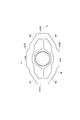
- the first movable portion 3 provided with the mirror surface 10 swings around the X axis (first axis) and the Y axis (second axis orthogonal to the first axis) orthogonal to each other. It is done.
- the actuator device 1 is used, for example, in an optical switch for optical communication, an optical scanner, and the like.
- the actuator device 1 is manufactured using MEMS technology (patterning, etching, etc.).
- the support portion 2 has, for example, a rectangular outer shape in a plan view, and is formed in a frame shape.
- the support portion 2 is disposed on one side in a direction orthogonal to the X axis and the Y axis with respect to the magnetic field generation portion 9.
- the first movable portion 3 is disposed inside the support portion 2 in a state of being separated from the magnetic field generating portion 9.
- the first movable portion 3 has a main body portion 3a, an annular portion 3b, and a pair of connecting portions 3c.
- the main body portion 3a has a circular shape in a plan view, but may be formed into an arbitrary shape such as an elliptical shape, a quadrangular shape, or a rhombus shape.
- the center P of the main body 3a in a plan view coincides with the intersection of the X axis and the Y axis.
- a mirror surface 10 is provided on the surface of the main body portion 3a opposite to the magnetic field generation portion with a metal film made of, for example, aluminum.
- the mirror surface 10 is provided on the entire surface of the surface, but may be provided on only a part of the surface.
- the annular portion 3 b is annularly formed so as to surround the main portion 3 a in a plan view.
- the second movable portion 4 is formed in a frame shape, and is disposed inside the support portion 2 so as to surround the first movable portion 3 in a state of being separated from the magnetic field generating portion 9.
- the detailed configuration of the second movable portion 4 will be described later.
- the first torsion bars 5 and 6 are disposed on both sides of the first movable portion 3 on the X axis.
- the first torsion bars 5 and 6 have the first movable portion 3 (annular portion 3b) on the X axis so that the first movable portion 3 can swing around the X axis (with the X axis as a center line).
- the second movable portion 4 is connected to each other.
- Each first torsion bar 5, 6 extends linearly along the X axis.
- the width of the end on the first movable portion 3 side of each of the first torsion bars 5 and 6 is equal to that of the first movable portion 3.
- the width of the end portion on the second movable portion 4 side increases as it approaches the second movable portion 4.
- the linear portions 11 extend in the Y-axis direction (second axis direction) parallel to the Y-axis, and are arranged side by side in the X-axis direction (first axis direction) parallel to the X-axis.
- the folded portion 12 alternately connects both ends of the adjacent linear portions 11.
- Each of the insulating layers 32 to 35 is made of, for example, silicon oxide, silicon nitride, silicon oxynitride or the like.
- Each of the insulating layers 32 to 35 is a surface of the support 2, the first movable portion 3, the second movable portion 4, the first torsion bars 5 and 6, and the second torsion bars 7 and 8 (a side opposite to the magnetic field generating portion 9 Is integrally formed so as to cover the surface of
- the second connection portions 42A and 42B are located on both sides of the first movable portion 3 on the Y axis. Each second connection portion 42A, 42B has a portion facing the first movable portion 3 in the Y-axis direction in plan view. Each second connection portion 42A, 42B extends along the X-axis direction. The second connection portions 42A and 42B are connected to the second torsion bars 7 and 8, respectively. That is, the second torsion bars 7 and 8 are connected to the second movable portion 4 at the second connection portions 42A and 42B.
- the first linear portions 43A and 43B are located on both sides of the second connection portion 42A in the X-axis direction, and are connected to the second connection portion 42A. Each first linear portion 43A, 43B extends along the X-axis direction. The first linear portions 43A and 43B are arranged symmetrically with respect to the Y axis. The second linear portions 44A and 44B are located on both sides of the second connection portion 42B in the X-axis direction, and are connected to the second connection portion 42B. Each second linear portion 44A, 44B extends along the X-axis direction. The second linear portions 44A and 44B are arranged symmetrically with respect to the Y axis.
- the third linear portions 45A and 45B are located on the opposite side of the first connection portions 42A with respect to the first linear portions 43A and 43B, and the first linear portions 43A and 43B and the first connection portions 41A, It is connected to 41B.
- the third linear portion 45A extends in a direction inclined by 45 degrees with respect to each of the X axis and the Y axis in plan view.
- the third linear portion 45B extends symmetrically with respect to the Y axis with respect to the third linear portion 45A.
- the direction in which the third linear portion 45A extends may be inclined at an angle other than 45 degrees with respect to the X axis and the Y axis.
- the configuration of the second connection portion 42A will be described in more detail with reference to FIG.
- the second connection portion 42B is configured symmetrically with respect to the X-axis with respect to the second connection portion 42A, and has a configuration similar to that of the second connection portion 42A.
- the inner edge 51 of the second connection portion 42A in plan view has one recess 52 recessed in the Y-axis direction.
- the recess 52 is recessed in the opposite side of the first movable portion 3 with respect to the inner edge of each of the first linear portions 43A, 43B.
- the recess 52 is located on the Y axis in plan view.
- the recess 52 is provided over the area of the second connection portion 42A facing the first movable portion 3 in a plan view.
- the inner edge 51 in the region where the recess 52 is formed is curved so as to be away from the first movable portion 3 as it approaches the Y axis.
- the inner edge 51 in the region where the recess 52 is not formed extends along the X-axis direction.
- the curvature of the inner edge 51 is continuous at the boundary between the region in which the recess 52 is formed and the region in which the recess 52 is not formed.
- the width of a certain portion in the second movable portion 4 is the distance between the inner edge and the outer edge of the portion in a plan view, in other words, the direction orthogonal to the X axis and Y axis, and the portion The width of the portion in the direction (width direction) orthogonal to the extension direction of
- the width of the first connection portion 41A is the width of the first connection portion 41A in the X-axis direction
- the width of the second connection portion 42A is the width of the second connection portion 42A in the Y-axis direction.
- each of the coils 14 and 15 includes the first connection portions 41A and 41B and each of the linear portions 43A to 46B. Extends along the extension direction of the The coils 14 and 15 provided in the third linear portion 45B and the fourth linear portion 46A extend in the direction orthogonal to the magnetic field generated by the magnetic field generator 9.
- the outer edge of the region R in which the coils 14 and 15 are disposed is the outer edge of the first connection portions 41A and 41B and the linear portions 43A to 46B.
- the inner edge of the region R is along the inner edge of the first connection portions 41A, 41B and the straight portions 43A to 46B.
- the coils 14 and 15 provided in the other second portion 56 extend in the direction orthogonal to the magnetic field generated by the magnetic field generator 9.
- the first portion 55 is disposed closer to the outer edge 53 than the inner edge 51 of the second connection portion 42A. That is, the distance between the first portion 55 and the inner edge 51 is larger than the distance between the first portion 55 and the outer edge 53.
- the pair of third portions 57 is located opposite to the first portion 55 with respect to each second portion 56, and is connected to the pair of second portions 56 and the region R in the first linear portions 43A and 43B. It is done.
- Each third portion 57 extends along the X-axis direction.
- the direction in which one second portion 56 extends may be inclined at an angle other than 45 degrees with respect to the X axis and the Y axis.
- each of the pair of second connection portions 42A and 42B located on both sides of the first movable portion 3 on the Y axis is the first connection portion 41A, in the second movable portion 4. It includes a portion having a wider width than the portions other than the portions 41B and the second connection portions 42A, 42B.
- the actuator device 1 includes coils 14 and 15 and a magnetic field generator 9. Thereby, while securing the arrangement space of the coils 14 and 15 in the second movable portion 4, securing of the resonance frequency of the second movable portion 4 around the Y axis and deformation of the second movable portion 4 around the X axis Coexistence with suppression can be aimed at.
- each coil 14, 15 has a portion extending along a direction orthogonal to the magnetic field. Therefore, the Lorentz force generated by the interaction between the current flowing through the coils 14 and 15 and the magnetic field can be increased.
- each second connection portion 42A, 42B includes a portion having a width larger than the width of each first connection portion 41A, 41B.
- the concave portion 52 is provided across the region facing the first movable portion 3 in each of the second connection portions 42A and 42B in a plan view. This makes it possible to more effectively increase the moment of inertia of the second movable portion 4 around the X-axis. Moreover, the space which the 1st movable part 3 rock
- first movable portion 3 and the second movable portion 4 are linearly operated around the Y axis
- first movable portion 3 and the second movable portion 4 may be resonantly operated around the Y axis.
- the pair of coils 14 and 15 is provided in the second movable portion 4 in the above embodiment, only one coil may be provided in the second movable portion 4. Even in this case, the input of the drive signal to the coil can swing the first movable portion around the X axis and swing the second movable portion 4 around the Y axis.
- a single coil for swinging the first movable portion 3 around the X axis is provided on the first movable portion 3 and a single coil for swinging the second movable portion 4 around the Y axis.
- a coil may be provided on the second movable portion 4.
- an electromotive force monitor coil for measuring an electromotive force may be provided in the second movable unit 4, or a temperature sensor coil for measuring a temperature may be provided in the support unit 2.
- the coils 14 and 15 may not be embedded in the second movable portion 4 and may be disposed on the second movable portion 4.
- the material and shape of each configuration are not limited to the above-described materials and shapes, and various materials and shapes can be adopted.
- the outer edge 53 of the second connection portions 42A and 42B may have a plurality of convex portions protruding in the Y-axis direction.
- the outer edge 53 may have a pair of projections arranged symmetrically with respect to the Y axis.
- the outer edge 53 between the two convex portions may extend linearly along the X-axis direction, and the second torsion bars 7 and 8 may be connected to the linear portion.
- the convex portion is not located on the Y axis in plan view.
Landscapes
- Engineering & Computer Science (AREA)
- Physics & Mathematics (AREA)
- Power Engineering (AREA)
- Computer Hardware Design (AREA)
- Microelectronics & Electronic Packaging (AREA)
- Optics & Photonics (AREA)
- General Physics & Mathematics (AREA)
- Electromagnetism (AREA)
- Mechanical Engineering (AREA)
- Chemical & Material Sciences (AREA)
- Analytical Chemistry (AREA)
- Micromachines (AREA)
- Mechanical Optical Scanning Systems (AREA)
- Mechanical Light Control Or Optical Switches (AREA)
- Apparatuses For Generation Of Mechanical Vibrations (AREA)
- Reciprocating, Oscillating Or Vibrating Motors (AREA)
Priority Applications (6)
| Application Number | Priority Date | Filing Date | Title |
|---|---|---|---|
| US16/766,996 US11485629B2 (en) | 2017-12-01 | 2018-11-26 | Actuator device with first and second movabale parts and connection portions having a depression portion and a protrusion portion |
| EP18883571.4A EP3719559A4 (en) | 2017-12-01 | 2018-11-26 | ACTUATOR DEVICE |
| CN201880077473.8A CN111433654B (zh) | 2017-12-01 | 2018-11-26 | 致动器装置 |
| KR1020207009599A KR20200095459A (ko) | 2017-12-01 | 2018-11-26 | 액추에이터 장치 |
| US17/950,323 US11673794B2 (en) | 2017-12-01 | 2022-09-22 | Actuator device |
| US18/140,693 US11939211B2 (en) | 2017-12-01 | 2023-04-28 | Actuator device |
Applications Claiming Priority (2)
| Application Number | Priority Date | Filing Date | Title |
|---|---|---|---|
| JP2017232060A JP6585147B2 (ja) | 2017-12-01 | 2017-12-01 | アクチュエータ装置 |
| JP2017-232060 | 2017-12-01 |
Related Child Applications (2)
| Application Number | Title | Priority Date | Filing Date |
|---|---|---|---|
| US16/766,996 A-371-Of-International US11485629B2 (en) | 2017-12-01 | 2018-11-26 | Actuator device with first and second movabale parts and connection portions having a depression portion and a protrusion portion |
| US17/950,323 Continuation US11673794B2 (en) | 2017-12-01 | 2022-09-22 | Actuator device |
Publications (1)
| Publication Number | Publication Date |
|---|---|
| WO2019107312A1 true WO2019107312A1 (ja) | 2019-06-06 |
Family
ID=66663964
Family Applications (1)
| Application Number | Title | Priority Date | Filing Date |
|---|---|---|---|
| PCT/JP2018/043413 WO2019107312A1 (ja) | 2017-12-01 | 2018-11-26 | アクチュエータ装置 |
Country Status (6)
| Country | Link |
|---|---|
| US (3) | US11485629B2 (zh) |
| EP (1) | EP3719559A4 (zh) |
| JP (1) | JP6585147B2 (zh) |
| KR (1) | KR20200095459A (zh) |
| CN (1) | CN111433654B (zh) |
| WO (1) | WO2019107312A1 (zh) |
Cited By (1)
| Publication number | Priority date | Publication date | Assignee | Title |
|---|---|---|---|---|
| WO2021065399A1 (ja) * | 2019-09-30 | 2021-04-08 | 浜松ホトニクス株式会社 | 光学デバイス |
Families Citing this family (1)
| Publication number | Priority date | Publication date | Assignee | Title |
|---|---|---|---|---|
| EP4198605A1 (en) * | 2017-02-28 | 2023-06-21 | Hamamatsu Photonics K.K. | Optical module |
Citations (5)
| Publication number | Priority date | Publication date | Assignee | Title |
|---|---|---|---|---|
| JP2014041234A (ja) | 2012-08-22 | 2014-03-06 | Seiko Epson Corp | アクチュエーター、光スキャナー、画像表示装置、ヘッドマウントディスプレイ |
| JP2014056211A (ja) * | 2012-09-14 | 2014-03-27 | Seiko Epson Corp | アクチュエーター、光スキャナー、画像表示装置およびヘッドマウントディスプレイ |
| WO2014162521A1 (ja) * | 2013-04-02 | 2014-10-09 | パイオニア株式会社 | アクチュエータ |
| WO2015015666A1 (ja) * | 2013-08-01 | 2015-02-05 | 浜松ホトニクス株式会社 | アクチュエータ装置及びミラー駆動装置 |
| JP2017181710A (ja) * | 2016-03-30 | 2017-10-05 | セイコーエプソン株式会社 | 光スキャナー用部材、光スキャナー、画像表示装置およびヘッドマウントディスプレイ |
Family Cites Families (90)
| Publication number | Priority date | Publication date | Assignee | Title |
|---|---|---|---|---|
| NL7802795A (nl) * | 1978-03-15 | 1979-09-18 | Philips Nv | Scheerapparaat. |
| JPS5567954A (en) * | 1978-11-16 | 1980-05-22 | Olympus Optical Co Ltd | Auto-reverse tape recorder |
| DE2851384A1 (de) * | 1978-11-28 | 1980-06-04 | Bohner & Koehle | Maschine zum druecken oder fliessdruecken von rotationssymmetrischen werkstuecken |
| DE2851562A1 (de) * | 1978-11-29 | 1980-06-12 | Rentrop Hubbert & Wagner | Sitz, insbesondere kraftfahrzeugsitz |
| US4260375A (en) * | 1979-12-13 | 1981-04-07 | Melvin Wallshein | Bent wire orthodontic spring clip |
| GB2070207B (en) * | 1980-02-19 | 1983-03-23 | Desoutter Ltd | Safety catch for a power tool |
| US4429909A (en) * | 1981-12-11 | 1984-02-07 | Lindquist John L | Restraint assembly for door exit devices |
| US5011122A (en) * | 1982-08-23 | 1991-04-30 | Frank Meyers | Resilient torsion arrangement |
| WO1984004812A1 (fr) * | 1983-05-31 | 1984-12-06 | Hirata Gensai | Consistometre |
| DE3323696A1 (de) * | 1983-07-01 | 1985-01-10 | Thyssen Industrie Ag, 4300 Essen | Verfahren und vorrichtung zum verlegen einer vorgefertigten wicklung eines linearmotors |
| DE3334881A1 (de) * | 1983-09-27 | 1985-04-11 | Fa. Carl Freudenberg, 6940 Weinheim | Gummikupplung |
| US4533803A (en) * | 1983-10-17 | 1985-08-06 | The Singer Company | Switch construction |
| US4630185A (en) * | 1985-10-30 | 1986-12-16 | Copeland Anthony S | Mechanical arm with two link members |
| DE3619408A1 (de) * | 1986-06-09 | 1987-12-10 | Battelle Institut E V | Anordnung zur gewinnung von geradsymmetrischen signalen |
| US4763967A (en) * | 1986-11-18 | 1988-08-16 | General Scanning, Inc. | Tunable resonant device |
| US4775870A (en) * | 1987-02-10 | 1988-10-04 | Texas Instruments Incorporated | Non-impact printer |
| EP0278753B1 (en) * | 1987-02-11 | 1993-01-07 | Gec Aerospace Limited | Improvements relating to transducers |
| US5253730A (en) * | 1988-06-08 | 1993-10-19 | Honda Giken Kogyo Kabushiki Kaisha | Power steering apparatus |
| US4908007A (en) * | 1988-11-23 | 1990-03-13 | Dayco Products, Inc. | Belt tensioner and method of making the same |
| US4952197A (en) * | 1988-11-23 | 1990-08-28 | Dayco Products, Inc. | Belt tensioner and method of making the same |
| US4886483A (en) * | 1988-11-23 | 1989-12-12 | Dayco Products, Inc. | Belt tensioner and method of making the same |
| US4978326A (en) * | 1988-11-23 | 1990-12-18 | Dayco Products, Inc. | Belt tensioner and method of making the same |
| US4913242A (en) * | 1989-08-07 | 1990-04-03 | Top Driver Enterprise Co., Ltd. | Electric screw driver |
| US5205792A (en) * | 1991-02-27 | 1993-04-27 | Dayco Products, Inc. | Tensioner for a power transmission belt and method of making the same |
| DE4110035C2 (de) * | 1991-03-27 | 1995-04-13 | Roland Man Druckmasch | Vorrichtung zum Verstellen von Elementen in Falzwerkzylindern von Rotationsdruckmaschinen |
| JPH05147383A (ja) * | 1991-11-26 | 1993-06-15 | Mutoh Ind Ltd | プロツタ用シ−ト部材搬送方法及び装置 |
| JPH05245590A (ja) * | 1992-03-04 | 1993-09-24 | Sumitomo Heavy Ind Ltd | 連続鋳造用鋳片厚さ可変モールド |
| JP2607006Y2 (ja) * | 1993-01-18 | 2001-03-19 | 旭光学工業株式会社 | カメラのズームファインダ装置 |
| CH689543A5 (fr) * | 1994-07-21 | 1999-06-15 | Rossignol Sa | Dispositif de fixation d'une chaussure sur un surf à neige. |
| EP0696694B2 (en) * | 1994-07-29 | 2004-02-04 | Aisin Seiki Kabushiki Kaisha | Torque absorbing disc |
| US5567109A (en) * | 1995-04-05 | 1996-10-22 | Eaton; Jay S. | Self-loading tobacco trailer |
| US5634681A (en) * | 1995-04-06 | 1997-06-03 | Gionta; Mark S. | Truck mounted work station |
| WO1996039643A1 (fr) * | 1995-06-05 | 1996-12-12 | Nihon Shingo Kabushiki Kaisha | Actionneur electromagnetique |
| US5748394A (en) * | 1995-07-26 | 1998-05-05 | Konica Corporation | Lens driving device |
| US5758705A (en) * | 1996-05-09 | 1998-06-02 | Kelley Company, Inc. | Roll-up door |
| US6188504B1 (en) * | 1996-06-28 | 2001-02-13 | Olympus Optical Co., Ltd. | Optical scanner |
| US5778928A (en) * | 1996-07-12 | 1998-07-14 | Aeroquip Corporation | Marine drain valve |
| US5999303A (en) * | 1997-03-24 | 1999-12-07 | Seagate Technology Inc. | Micro-machined mirror using tethered elements |
| JP2001519726A (ja) * | 1997-04-01 | 2001-10-23 | クセロス・インク | 微細加工捩り振動子の動的特性の調整 |
| GB9707552D0 (en) * | 1997-04-15 | 1997-06-04 | Fujifilm Electronic Imaging Li | Image viewing apparatus |
| US5875881A (en) * | 1997-07-21 | 1999-03-02 | Scorpio Conveyor Products (Proprietary) Limited | Plough scraper mounting arrangement |
| AU738112B2 (en) * | 1997-07-25 | 2001-09-06 | Scorpio Conveyor Products (Proprietary) Limited | Conveyor scraper and mounting of scraper blade |
| US6201629B1 (en) * | 1997-08-27 | 2001-03-13 | Microoptical Corporation | Torsional micro-mechanical mirror system |
| JP3818752B2 (ja) * | 1997-09-24 | 2006-09-06 | Smc株式会社 | ロッドレスシリンダ |
| DE19742314C2 (de) * | 1997-09-25 | 2000-06-21 | Daimler Chrysler Ag | Tragende Struktur |
| US5933066A (en) * | 1997-11-13 | 1999-08-03 | Eaton Corporation | Circuit interrupter with terminal shield and wire trough |
| EP1119792A2 (en) * | 1998-09-02 | 2001-08-01 | Xros, Inc. | Micromachined members coupled for relative rotation by torsional flexure hinges |
| US20020130561A1 (en) * | 2001-03-18 | 2002-09-19 | Temesvary Viktoria A. | Moving coil motor and implementations in MEMS based optical switches |
| US7872394B1 (en) * | 2001-12-13 | 2011-01-18 | Joseph E Ford | MEMS device with two axes comb drive actuators |
| AU2002335243A1 (en) * | 2002-10-10 | 2004-05-04 | Fujitsu Media Devices Limited | Micro moving element comprising torsion bar |
| US7446911B2 (en) * | 2002-11-26 | 2008-11-04 | Brother Kogyo Kabushiki Kaisha | Optical scanning apparatus and image forming apparatus |
| WO2004092745A1 (de) * | 2003-04-15 | 2004-10-28 | Fraunhofer-Gesellschaft zur Förderung der angewandten Forschung e. V. | Mikromechanisches bauelement mit einstellbarer resonanzfrequenz |
| US6965177B2 (en) * | 2003-06-18 | 2005-11-15 | Texas Instruments Incorporated | Pulse drive of resonant MEMS devices |
| JP4027359B2 (ja) * | 2003-12-25 | 2007-12-26 | キヤノン株式会社 | マイクロ揺動体、光偏向器、画像形成装置 |
| US7233343B2 (en) * | 2004-11-24 | 2007-06-19 | Texas Instruments Incorporated | Serial printing with multiple torsional hinged MEMS mirrors |
| JP4385937B2 (ja) * | 2004-12-15 | 2009-12-16 | セイコーエプソン株式会社 | アクチュエータ |
| DE102005033800B4 (de) * | 2005-07-13 | 2016-09-15 | Fraunhofer-Gesellschaft zur Förderung der angewandten Forschung e.V. | Mikromechanisches optisches Element mit einer reflektierenden Fläche sowie dessen Verwendung |
| JP4935013B2 (ja) * | 2005-07-21 | 2012-05-23 | ブラザー工業株式会社 | 光走査装置、画像表示装置及び光スキャナの共振周波数変更方法並びに反射ミラー位置の補正方法 |
| US20070222334A1 (en) * | 2006-03-24 | 2007-09-27 | Chang-Feng Wan | Microelectromechanical step actuator capable of both analog and digital movements |
| JP5098254B2 (ja) * | 2006-08-29 | 2012-12-12 | 富士通株式会社 | マイクロ揺動素子 |
| DE102007021920B8 (de) * | 2007-05-10 | 2011-12-29 | Fraunhofer-Gesellschaft zur Förderung der angewandten Forschung e.V. | Vorrichtung zum Entwerfen eines mikromechanischen Bauelements mit angepasster Empfindlichkeit, Verfahren zur Herstellung eines mikromechanischen Bauelements und eines mikromechanischen Systems |
| TWI341602B (en) * | 2007-08-15 | 2011-05-01 | Nat Univ Tsing Hua | Magnetic element and manufacturing method therefor |
| JP5391579B2 (ja) * | 2008-05-15 | 2014-01-15 | 船井電機株式会社 | 振動素子 |
| DE102008049647B4 (de) * | 2008-09-30 | 2011-11-24 | Technische Universität Dresden | Mikromechanisches Element und Verfahren zum Betreiben eines mikromechanischen Elements |
| US8218218B2 (en) * | 2009-04-08 | 2012-07-10 | Microvision, Inc. | Fatigue resistant MEMS apparatus and system |
| JP5444968B2 (ja) * | 2009-05-11 | 2014-03-19 | ミツミ電機株式会社 | アクチュエータ及びこれを用いた光走査装置 |
| JP2011107675A (ja) * | 2009-10-20 | 2011-06-02 | Seiko Epson Corp | 光偏向素子、光偏向器、及び画像形成装置 |
| WO2011061833A1 (ja) * | 2009-11-19 | 2011-05-26 | パイオニア株式会社 | 駆動装置 |
| JP5736766B2 (ja) * | 2010-12-22 | 2015-06-17 | ミツミ電機株式会社 | 光走査装置 |
| JP5909862B2 (ja) * | 2011-04-06 | 2016-04-27 | セイコーエプソン株式会社 | アクチュエーター、光スキャナーおよび画像形成装置 |
| JP5842369B2 (ja) * | 2011-04-11 | 2016-01-13 | セイコーエプソン株式会社 | アクチュエーターの製造方法、光スキャナーの製造方法および画像形成装置の製造方法、アクチュエーター、光スキャナーおよび画像形成装置 |
| US9120667B2 (en) * | 2011-06-20 | 2015-09-01 | International Business Machines Corporation | Micro-electro-mechanical system (MEMS) and related actuator bumps, methods of manufacture and design structures |
| JP2013122375A (ja) * | 2011-11-07 | 2013-06-20 | Seiko Epson Corp | 物理量検出デバイス、物理量検出器、および電子機器 |
| US10730742B2 (en) * | 2012-01-24 | 2020-08-04 | Pioneer Corporation | Actuator with plurality of torsion bars having varying spring constant |
| JP5962900B2 (ja) * | 2012-04-02 | 2016-08-03 | セイコーエプソン株式会社 | 物理量センサーおよび電子機器 |
| JP5935986B2 (ja) * | 2012-04-06 | 2016-06-15 | セイコーエプソン株式会社 | 物理量センサーおよび電子機器 |
| JP5930183B2 (ja) * | 2012-04-09 | 2016-06-08 | セイコーエプソン株式会社 | 物理量センサーおよび電子機器 |
| JP6098780B2 (ja) * | 2012-04-19 | 2017-03-22 | セイコーエプソン株式会社 | ジャイロセンサーおよび電子機器 |
| US9291815B2 (en) * | 2012-05-07 | 2016-03-22 | Panasonic Intellectual Property Management Co., Ltd. | Optical reflection element |
| CN103728467B (zh) * | 2012-10-16 | 2016-03-16 | 无锡华润上华半导体有限公司 | 平行板电容器 |
| WO2014109170A1 (ja) * | 2013-01-11 | 2014-07-17 | 浜松ホトニクス株式会社 | ミラー駆動装置 |
| DE102013209234B4 (de) * | 2013-05-17 | 2018-04-05 | Fraunhofer-Gesellschaft zur Förderung der angewandten Forschung e.V. | Vorrichtung mit einem schwingfähig aufgehängten optischen Element |
| JP2015087444A (ja) * | 2013-10-29 | 2015-05-07 | セイコーエプソン株式会社 | 光スキャナー、画像表示装置、ヘッドマウントディスプレイおよびヘッドアップディスプレイ |
| JP6233010B2 (ja) * | 2013-12-26 | 2017-11-22 | セイコーエプソン株式会社 | 光スキャナー、画像表示装置およびヘッドマウントディスプレイ |
| KR101565684B1 (ko) * | 2014-03-14 | 2015-11-03 | 삼성전기주식회사 | Mems 센서용 검출모듈 및 이를 포함하는 mems 센서 |
| US9910270B2 (en) * | 2015-10-12 | 2018-03-06 | Intel Corporation | Electro-mechanical designs for MEMS scanning mirrors |
| ITUB20155997A1 (it) * | 2015-11-30 | 2017-05-30 | St Microelectronics Srl | Struttura micromeccanica ad attuazione biassiale e relativo dispositivo mems |
| JP6696777B2 (ja) * | 2016-01-21 | 2020-05-20 | 浜松ホトニクス株式会社 | アクチュエータ装置 |
| JP2017181715A (ja) * | 2016-03-30 | 2017-10-05 | セイコーエプソン株式会社 | 光スキャナー用部材、光スキャナー、光スキャナーの製造方法、画像表示装置およびヘッドマウントディスプレイ |
| JP6924090B2 (ja) * | 2017-07-21 | 2021-08-25 | 浜松ホトニクス株式会社 | アクチュエータ装置 |
-
2017
- 2017-12-01 JP JP2017232060A patent/JP6585147B2/ja active Active
-
2018
- 2018-11-26 EP EP18883571.4A patent/EP3719559A4/en active Pending
- 2018-11-26 KR KR1020207009599A patent/KR20200095459A/ko unknown
- 2018-11-26 US US16/766,996 patent/US11485629B2/en active Active
- 2018-11-26 WO PCT/JP2018/043413 patent/WO2019107312A1/ja unknown
- 2018-11-26 CN CN201880077473.8A patent/CN111433654B/zh active Active
-
2022
- 2022-09-22 US US17/950,323 patent/US11673794B2/en active Active
-
2023
- 2023-04-28 US US18/140,693 patent/US11939211B2/en active Active
Patent Citations (5)
| Publication number | Priority date | Publication date | Assignee | Title |
|---|---|---|---|---|
| JP2014041234A (ja) | 2012-08-22 | 2014-03-06 | Seiko Epson Corp | アクチュエーター、光スキャナー、画像表示装置、ヘッドマウントディスプレイ |
| JP2014056211A (ja) * | 2012-09-14 | 2014-03-27 | Seiko Epson Corp | アクチュエーター、光スキャナー、画像表示装置およびヘッドマウントディスプレイ |
| WO2014162521A1 (ja) * | 2013-04-02 | 2014-10-09 | パイオニア株式会社 | アクチュエータ |
| WO2015015666A1 (ja) * | 2013-08-01 | 2015-02-05 | 浜松ホトニクス株式会社 | アクチュエータ装置及びミラー駆動装置 |
| JP2017181710A (ja) * | 2016-03-30 | 2017-10-05 | セイコーエプソン株式会社 | 光スキャナー用部材、光スキャナー、画像表示装置およびヘッドマウントディスプレイ |
Cited By (4)
| Publication number | Priority date | Publication date | Assignee | Title |
|---|---|---|---|---|
| WO2021065399A1 (ja) * | 2019-09-30 | 2021-04-08 | 浜松ホトニクス株式会社 | 光学デバイス |
| CN114450618A (zh) * | 2019-09-30 | 2022-05-06 | 浜松光子学株式会社 | 光学装置 |
| CN114450618B (zh) * | 2019-09-30 | 2024-03-08 | 浜松光子学株式会社 | 光学装置 |
| JP7481821B2 (ja) | 2019-09-30 | 2024-05-13 | 浜松ホトニクス株式会社 | 光学デバイス |
Also Published As
| Publication number | Publication date |
|---|---|
| CN111433654A (zh) | 2020-07-17 |
| US11939211B2 (en) | 2024-03-26 |
| JP6585147B2 (ja) | 2019-10-02 |
| EP3719559A1 (en) | 2020-10-07 |
| US20230013912A1 (en) | 2023-01-19 |
| KR20200095459A (ko) | 2020-08-10 |
| US11673794B2 (en) | 2023-06-13 |
| EP3719559A4 (en) | 2021-09-15 |
| CN111433654B (zh) | 2021-10-01 |
| US20230264947A1 (en) | 2023-08-24 |
| JP2019101234A (ja) | 2019-06-24 |
| US11485629B2 (en) | 2022-11-01 |
| US20210032095A1 (en) | 2021-02-04 |
Similar Documents
| Publication | Publication Date | Title |
|---|---|---|
| US11939211B2 (en) | Actuator device | |
| JP6546370B1 (ja) | アクチュエータ装置 | |
| JP2024050649A (ja) | アクチュエータ装置、及びアクチュエータ装置の製造方法 | |
| JP7221180B2 (ja) | 光学デバイス | |
| JP7229160B2 (ja) | ミラー装置 | |
| JP6591135B1 (ja) | 光学デバイス |
Legal Events
| Date | Code | Title | Description |
|---|---|---|---|
| 121 | Ep: the epo has been informed by wipo that ep was designated in this application |
Ref document number: 18883571 Country of ref document: EP Kind code of ref document: A1 |
|
| NENP | Non-entry into the national phase |
Ref country code: DE |
|
| ENP | Entry into the national phase |
Ref document number: 2018883571 Country of ref document: EP Effective date: 20200701 |