WO2019107312A1 - アクチュエータ装置 - Google Patents
アクチュエータ装置 Download PDFInfo
- Publication number
- WO2019107312A1 WO2019107312A1 PCT/JP2018/043413 JP2018043413W WO2019107312A1 WO 2019107312 A1 WO2019107312 A1 WO 2019107312A1 JP 2018043413 W JP2018043413 W JP 2018043413W WO 2019107312 A1 WO2019107312 A1 WO 2019107312A1
- Authority
- WO
- WIPO (PCT)
- Prior art keywords
- axis
- pair
- movable portion
- portions
- linear
- Prior art date
Links
Images


Classifications
-
- B—PERFORMING OPERATIONS; TRANSPORTING
- B81—MICROSTRUCTURAL TECHNOLOGY
- B81B—MICROSTRUCTURAL DEVICES OR SYSTEMS, e.g. MICROMECHANICAL DEVICES
- B81B3/00—Devices comprising flexible or deformable elements, e.g. comprising elastic tongues or membranes
- B81B3/0018—Structures acting upon the moving or flexible element for transforming energy into mechanical movement or vice versa, i.e. actuators, sensors, generators
- B81B3/0021—Transducers for transforming electrical into mechanical energy or vice versa
-
- G—PHYSICS
- G02—OPTICS
- G02B—OPTICAL ELEMENTS, SYSTEMS OR APPARATUS
- G02B26/00—Optical devices or arrangements for the control of light using movable or deformable optical elements
- G02B26/08—Optical devices or arrangements for the control of light using movable or deformable optical elements for controlling the direction of light
- G02B26/0816—Optical devices or arrangements for the control of light using movable or deformable optical elements for controlling the direction of light by means of one or more reflecting elements
- G02B26/0833—Optical devices or arrangements for the control of light using movable or deformable optical elements for controlling the direction of light by means of one or more reflecting elements the reflecting element being a micromechanical device, e.g. a MEMS mirror, DMD
- G02B26/085—Optical devices or arrangements for the control of light using movable or deformable optical elements for controlling the direction of light by means of one or more reflecting elements the reflecting element being a micromechanical device, e.g. a MEMS mirror, DMD the reflecting means being moved or deformed by electromagnetic means
-
- B—PERFORMING OPERATIONS; TRANSPORTING
- B06—GENERATING OR TRANSMITTING MECHANICAL VIBRATIONS IN GENERAL
- B06B—METHODS OR APPARATUS FOR GENERATING OR TRANSMITTING MECHANICAL VIBRATIONS OF INFRASONIC, SONIC, OR ULTRASONIC FREQUENCY, e.g. FOR PERFORMING MECHANICAL WORK IN GENERAL
- B06B1/00—Methods or apparatus for generating mechanical vibrations of infrasonic, sonic, or ultrasonic frequency
- B06B1/02—Methods or apparatus for generating mechanical vibrations of infrasonic, sonic, or ultrasonic frequency making use of electrical energy
- B06B1/04—Methods or apparatus for generating mechanical vibrations of infrasonic, sonic, or ultrasonic frequency making use of electrical energy operating with electromagnetism
-
- B—PERFORMING OPERATIONS; TRANSPORTING
- B81—MICROSTRUCTURAL TECHNOLOGY
- B81B—MICROSTRUCTURAL DEVICES OR SYSTEMS, e.g. MICROMECHANICAL DEVICES
- B81B3/00—Devices comprising flexible or deformable elements, e.g. comprising elastic tongues or membranes
-
- B—PERFORMING OPERATIONS; TRANSPORTING
- B81—MICROSTRUCTURAL TECHNOLOGY
- B81B—MICROSTRUCTURAL DEVICES OR SYSTEMS, e.g. MICROMECHANICAL DEVICES
- B81B3/00—Devices comprising flexible or deformable elements, e.g. comprising elastic tongues or membranes
- B81B3/0035—Constitution or structural means for controlling the movement of the flexible or deformable elements
- B81B3/004—Angular deflection
- B81B3/0045—Improve properties related to angular swinging, e.g. control resonance frequency
-
- G—PHYSICS
- G02—OPTICS
- G02B—OPTICAL ELEMENTS, SYSTEMS OR APPARATUS
- G02B26/00—Optical devices or arrangements for the control of light using movable or deformable optical elements
- G02B26/02—Optical devices or arrangements for the control of light using movable or deformable optical elements for controlling the intensity of light
-
- G—PHYSICS
- G02—OPTICS
- G02B—OPTICAL ELEMENTS, SYSTEMS OR APPARATUS
- G02B26/00—Optical devices or arrangements for the control of light using movable or deformable optical elements
- G02B26/08—Optical devices or arrangements for the control of light using movable or deformable optical elements for controlling the direction of light
- G02B26/10—Scanning systems
-
- H—ELECTRICITY
- H02—GENERATION; CONVERSION OR DISTRIBUTION OF ELECTRIC POWER
- H02K—DYNAMO-ELECTRIC MACHINES
- H02K33/00—Motors with reciprocating, oscillating or vibrating magnet, armature or coil system
- H02K33/02—Motors with reciprocating, oscillating or vibrating magnet, armature or coil system with armatures moved one way by energisation of a single coil system and returned by mechanical force, e.g. by springs
-
- H—ELECTRICITY
- H02—GENERATION; CONVERSION OR DISTRIBUTION OF ELECTRIC POWER
- H02K—DYNAMO-ELECTRIC MACHINES
- H02K33/00—Motors with reciprocating, oscillating or vibrating magnet, armature or coil system
- H02K33/18—Motors with reciprocating, oscillating or vibrating magnet, armature or coil system with coil systems moving upon intermittent or reversed energisation thereof by interaction with a fixed field system, e.g. permanent magnets
-
- B—PERFORMING OPERATIONS; TRANSPORTING
- B81—MICROSTRUCTURAL TECHNOLOGY
- B81B—MICROSTRUCTURAL DEVICES OR SYSTEMS, e.g. MICROMECHANICAL DEVICES
- B81B2201/00—Specific applications of microelectromechanical systems
- B81B2201/04—Optical MEMS
- B81B2201/045—Optical switches
-
- G—PHYSICS
- G02—OPTICS
- G02B—OPTICAL ELEMENTS, SYSTEMS OR APPARATUS
- G02B26/00—Optical devices or arrangements for the control of light using movable or deformable optical elements
- G02B26/08—Optical devices or arrangements for the control of light using movable or deformable optical elements for controlling the direction of light
- G02B26/10—Scanning systems
- G02B26/101—Scanning systems with both horizontal and vertical deflecting means, e.g. raster or XY scanners
-
- H—ELECTRICITY
- H02—GENERATION; CONVERSION OR DISTRIBUTION OF ELECTRIC POWER
- H02K—DYNAMO-ELECTRIC MACHINES
- H02K11/00—Structural association of dynamo-electric machines with electric components or with devices for shielding, monitoring or protection
- H02K11/20—Structural association of dynamo-electric machines with electric components or with devices for shielding, monitoring or protection for measuring, monitoring, testing, protecting or switching
- H02K11/25—Devices for sensing temperature, or actuated thereby
Definitions
- the resonance frequency of the second movable portion around the second axis be high in order to suppress the vibration of the second movable portion due to an unintended external force.
- the reaction may cause the second movable portion to deform around the first axis to the side opposite to the first movable portion.
- it may be necessary to largely deform the second connection portion.
- stress may occur in unintended locations. Therefore, it is desirable that deformation of the second movable portion around the first axis be suppressed.
- An actuator device includes a support portion, a first movable portion, a frame-shaped second movable portion arranged to surround the first movable portion, and a first axis parallel to the first axis. Pair of first connecting parts arranged on both sides of the first movable part in the direction to connect the first movable part and the second movable part to each other so that the first movable part can swing around the first axis And the second movable portion disposed on both sides of the second movable portion in the first axial direction parallel to the second axis orthogonal to the first axis, and the second movable portion can swing around the second axial line.
- the coil is an outer edge on the second axis, as viewed from the direction orthogonal to the first axis and the second axis, than the respective inner edges of the pair of second connection portions. It may be arranged at a position close to In this case, the moment of inertia of the second movable portion around the first axis can be more effectively increased.
- the coil may have a portion extending along a direction orthogonal to the magnetic field. In this case, the Lorentz force generated by the interaction between the current flowing through the coil and the magnetic field can be increased.
- the coil may be made of a metal material having a higher density than the material forming the second movable portion, and may be embedded in the second movable portion. In this case, the moment of inertia of the second movable portion around the first axis can be more effectively increased.
- each of the pair of second connection portions may include a portion having a larger width than each of the pair of first connection portions. In this case, it is possible to more effectively increase the moment of inertia of the second movable portion around the first axis while suppressing the increase in the moment of inertia of the second movable portion around the second axis more effectively.
- each of the pair of second connection portions may extend in a meandering manner when viewed from a direction orthogonal to the first axis and the second axis.
- the strength of each second connection portion can be improved, and adjustment of the spring constant of each second connection portion can be facilitated.
- the apparatus can be prevented from increasing in size in the second axial direction.
- an actuator device in which a first movable portion is swung around a first axis and a second movable portion surrounding the first movable portion is swung around a second axis. It is possible to achieve both the securing of the resonant frequency of the second movable portion around the two axes and the suppression of the deformation of the second movable portion around the first axis.
- FIG. 2 is a cross-sectional view taken along the line II-II shown in FIG. It is a top view which expands and shows a part of FIG. It is a top view which shows a modification.
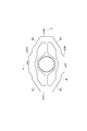
- the first movable portion 3 provided with the mirror surface 10 swings around the X axis (first axis) and the Y axis (second axis orthogonal to the first axis) orthogonal to each other. It is done.
- the actuator device 1 is used, for example, in an optical switch for optical communication, an optical scanner, and the like.
- the actuator device 1 is manufactured using MEMS technology (patterning, etching, etc.).
- the support portion 2 has, for example, a rectangular outer shape in a plan view, and is formed in a frame shape.
- the support portion 2 is disposed on one side in a direction orthogonal to the X axis and the Y axis with respect to the magnetic field generation portion 9.
- the first movable portion 3 is disposed inside the support portion 2 in a state of being separated from the magnetic field generating portion 9.
- the first movable portion 3 has a main body portion 3a, an annular portion 3b, and a pair of connecting portions 3c.
- the main body portion 3a has a circular shape in a plan view, but may be formed into an arbitrary shape such as an elliptical shape, a quadrangular shape, or a rhombus shape.
- the center P of the main body 3a in a plan view coincides with the intersection of the X axis and the Y axis.
- a mirror surface 10 is provided on the surface of the main body portion 3a opposite to the magnetic field generation portion with a metal film made of, for example, aluminum.
- the mirror surface 10 is provided on the entire surface of the surface, but may be provided on only a part of the surface.
- the annular portion 3 b is annularly formed so as to surround the main portion 3 a in a plan view.
- the second movable portion 4 is formed in a frame shape, and is disposed inside the support portion 2 so as to surround the first movable portion 3 in a state of being separated from the magnetic field generating portion 9.
- the detailed configuration of the second movable portion 4 will be described later.
- the first torsion bars 5 and 6 are disposed on both sides of the first movable portion 3 on the X axis.
- the first torsion bars 5 and 6 have the first movable portion 3 (annular portion 3b) on the X axis so that the first movable portion 3 can swing around the X axis (with the X axis as a center line).
- the second movable portion 4 is connected to each other.
- Each first torsion bar 5, 6 extends linearly along the X axis.
- the width of the end on the first movable portion 3 side of each of the first torsion bars 5 and 6 is equal to that of the first movable portion 3.
- the width of the end portion on the second movable portion 4 side increases as it approaches the second movable portion 4.
- the linear portions 11 extend in the Y-axis direction (second axis direction) parallel to the Y-axis, and are arranged side by side in the X-axis direction (first axis direction) parallel to the X-axis.
- the folded portion 12 alternately connects both ends of the adjacent linear portions 11.
- Each of the insulating layers 32 to 35 is made of, for example, silicon oxide, silicon nitride, silicon oxynitride or the like.
- Each of the insulating layers 32 to 35 is a surface of the support 2, the first movable portion 3, the second movable portion 4, the first torsion bars 5 and 6, and the second torsion bars 7 and 8 (a side opposite to the magnetic field generating portion 9 Is integrally formed so as to cover the surface of
- the second connection portions 42A and 42B are located on both sides of the first movable portion 3 on the Y axis. Each second connection portion 42A, 42B has a portion facing the first movable portion 3 in the Y-axis direction in plan view. Each second connection portion 42A, 42B extends along the X-axis direction. The second connection portions 42A and 42B are connected to the second torsion bars 7 and 8, respectively. That is, the second torsion bars 7 and 8 are connected to the second movable portion 4 at the second connection portions 42A and 42B.
- the first linear portions 43A and 43B are located on both sides of the second connection portion 42A in the X-axis direction, and are connected to the second connection portion 42A. Each first linear portion 43A, 43B extends along the X-axis direction. The first linear portions 43A and 43B are arranged symmetrically with respect to the Y axis. The second linear portions 44A and 44B are located on both sides of the second connection portion 42B in the X-axis direction, and are connected to the second connection portion 42B. Each second linear portion 44A, 44B extends along the X-axis direction. The second linear portions 44A and 44B are arranged symmetrically with respect to the Y axis.
- the third linear portions 45A and 45B are located on the opposite side of the first connection portions 42A with respect to the first linear portions 43A and 43B, and the first linear portions 43A and 43B and the first connection portions 41A, It is connected to 41B.
- the third linear portion 45A extends in a direction inclined by 45 degrees with respect to each of the X axis and the Y axis in plan view.
- the third linear portion 45B extends symmetrically with respect to the Y axis with respect to the third linear portion 45A.
- the direction in which the third linear portion 45A extends may be inclined at an angle other than 45 degrees with respect to the X axis and the Y axis.
- the configuration of the second connection portion 42A will be described in more detail with reference to FIG.
- the second connection portion 42B is configured symmetrically with respect to the X-axis with respect to the second connection portion 42A, and has a configuration similar to that of the second connection portion 42A.
- the inner edge 51 of the second connection portion 42A in plan view has one recess 52 recessed in the Y-axis direction.
- the recess 52 is recessed in the opposite side of the first movable portion 3 with respect to the inner edge of each of the first linear portions 43A, 43B.
- the recess 52 is located on the Y axis in plan view.
- the recess 52 is provided over the area of the second connection portion 42A facing the first movable portion 3 in a plan view.
- the inner edge 51 in the region where the recess 52 is formed is curved so as to be away from the first movable portion 3 as it approaches the Y axis.
- the inner edge 51 in the region where the recess 52 is not formed extends along the X-axis direction.
- the curvature of the inner edge 51 is continuous at the boundary between the region in which the recess 52 is formed and the region in which the recess 52 is not formed.
- the width of a certain portion in the second movable portion 4 is the distance between the inner edge and the outer edge of the portion in a plan view, in other words, the direction orthogonal to the X axis and Y axis, and the portion The width of the portion in the direction (width direction) orthogonal to the extension direction of
- the width of the first connection portion 41A is the width of the first connection portion 41A in the X-axis direction
- the width of the second connection portion 42A is the width of the second connection portion 42A in the Y-axis direction.
- each of the coils 14 and 15 includes the first connection portions 41A and 41B and each of the linear portions 43A to 46B. Extends along the extension direction of the The coils 14 and 15 provided in the third linear portion 45B and the fourth linear portion 46A extend in the direction orthogonal to the magnetic field generated by the magnetic field generator 9.
- the outer edge of the region R in which the coils 14 and 15 are disposed is the outer edge of the first connection portions 41A and 41B and the linear portions 43A to 46B.
- the inner edge of the region R is along the inner edge of the first connection portions 41A, 41B and the straight portions 43A to 46B.
- the coils 14 and 15 provided in the other second portion 56 extend in the direction orthogonal to the magnetic field generated by the magnetic field generator 9.
- the first portion 55 is disposed closer to the outer edge 53 than the inner edge 51 of the second connection portion 42A. That is, the distance between the first portion 55 and the inner edge 51 is larger than the distance between the first portion 55 and the outer edge 53.
- the pair of third portions 57 is located opposite to the first portion 55 with respect to each second portion 56, and is connected to the pair of second portions 56 and the region R in the first linear portions 43A and 43B. It is done.
- Each third portion 57 extends along the X-axis direction.
- the direction in which one second portion 56 extends may be inclined at an angle other than 45 degrees with respect to the X axis and the Y axis.
- each of the pair of second connection portions 42A and 42B located on both sides of the first movable portion 3 on the Y axis is the first connection portion 41A, in the second movable portion 4. It includes a portion having a wider width than the portions other than the portions 41B and the second connection portions 42A, 42B.
- the actuator device 1 includes coils 14 and 15 and a magnetic field generator 9. Thereby, while securing the arrangement space of the coils 14 and 15 in the second movable portion 4, securing of the resonance frequency of the second movable portion 4 around the Y axis and deformation of the second movable portion 4 around the X axis Coexistence with suppression can be aimed at.
- each coil 14, 15 has a portion extending along a direction orthogonal to the magnetic field. Therefore, the Lorentz force generated by the interaction between the current flowing through the coils 14 and 15 and the magnetic field can be increased.
- each second connection portion 42A, 42B includes a portion having a width larger than the width of each first connection portion 41A, 41B.
- the concave portion 52 is provided across the region facing the first movable portion 3 in each of the second connection portions 42A and 42B in a plan view. This makes it possible to more effectively increase the moment of inertia of the second movable portion 4 around the X-axis. Moreover, the space which the 1st movable part 3 rock
- first movable portion 3 and the second movable portion 4 are linearly operated around the Y axis
- first movable portion 3 and the second movable portion 4 may be resonantly operated around the Y axis.
- the pair of coils 14 and 15 is provided in the second movable portion 4 in the above embodiment, only one coil may be provided in the second movable portion 4. Even in this case, the input of the drive signal to the coil can swing the first movable portion around the X axis and swing the second movable portion 4 around the Y axis.
- a single coil for swinging the first movable portion 3 around the X axis is provided on the first movable portion 3 and a single coil for swinging the second movable portion 4 around the Y axis.
- a coil may be provided on the second movable portion 4.
- an electromotive force monitor coil for measuring an electromotive force may be provided in the second movable unit 4, or a temperature sensor coil for measuring a temperature may be provided in the support unit 2.
- the coils 14 and 15 may not be embedded in the second movable portion 4 and may be disposed on the second movable portion 4.
- the material and shape of each configuration are not limited to the above-described materials and shapes, and various materials and shapes can be adopted.
- the outer edge 53 of the second connection portions 42A and 42B may have a plurality of convex portions protruding in the Y-axis direction.
- the outer edge 53 may have a pair of projections arranged symmetrically with respect to the Y axis.
- the outer edge 53 between the two convex portions may extend linearly along the X-axis direction, and the second torsion bars 7 and 8 may be connected to the linear portion.
- the convex portion is not located on the Y axis in plan view.
Abstract
アクチュエータ装置は、支持部と、第1可動部と、第2可動部と、第2連結部と、を備える。第2可動部は、第1軸線上における第1可動部の両側に位置し、一対の第1連結部に接続された一対の第1接続部と、第2軸線上における第1可動部の両側に位置し、一対の第2連結部に接続された一対の第2接続部と、を有する。一対の第2接続部のそれぞれは、第1軸線及び第2軸線に直交する方向から見た場合に、第2可動部における一対の第1接続部及び一対の第2接続部以外の部分よりも広い幅を有する部分を含む。第1軸線及び第2軸線に直交する方向から見た場合における一対の第2接続部のそれぞれの内縁は、第2軸方向に窪む凹部を有し、第1軸線及び第2軸線に直交する方向から見た場合における一対の第2接続部のそれぞれの外縁は、第2軸方向に突出する凸部を有する。
Description
本開示の一側面は、例えばMEMS(Micro Electro Mechanical Systems)デバイスとして構成されたアクチュエータ装置に関する。
MEMSデバイスとして、支持部と、第1可動部と、第1可動部を囲む枠状の第2可動部と、第1軸線上において第1可動部と第2可動部とを互いに連結する一対の第1連結部と、第1軸線に直交する第2軸線上において第2可動部と支持部とを互いに連結する一対の第2連結部と、を備えるアクチュエータ装置が知られている。このようなアクチュエータ装置では、第1可動部が第1軸線周りに揺動させられると共に、第2可動部が第1可動部と共に第2軸線周りに揺動させられる(例えば特許文献1参照)。
上述したようなアクチュエータ装置では、意図しない外力によって第2可動部が振動することを抑制するために、第2軸線周りにおける第2可動部の共振周波数が高いことが望まれる。一方で、第1可動部が第1軸線周りに揺動すると、その反動によって第2可動部が第1軸線周りに第1可動部とは反対側に変形することがある。この場合、第1可動部を規定量だけ揺動させるために第2連結部を大きく変形させる必要が生じるおそれがある。また、意図しない箇所に応力が生じるおそれもある。そのため、第1軸線周りにおける第2可動部の変形は抑制されることが望ましい。
本開示の一側面は、第1可動部が第1軸線周りに揺動させられると共に、第1可動部を囲む第2可動部が第2軸線周りに揺動させられるアクチュエータ装置において、第2軸線周りにおける第2可動部の共振周波数の確保と、第1軸線周りにおける第2可動部の変形の抑制との両立を図ることができるアクチュエータ装置を提供することを目的とする。
本開示の一側面に係るアクチュエータ装置は、支持部と、第1可動部と、第1可動部を囲むように配置された枠状の第2可動部と、第1軸線に平行な第1軸方向における第1可動部の両側に配置され、第1軸線周りに第1可動部が揺動可能となるように、第1可動部と第2可動部とを互いに連結する一対の第1連結部と、第1軸線に直交する第2軸線に平行な第1軸方向における第2可動部の両側に配置され、第2軸線周りに第2可動部が揺動可能となるように、第2可動部と支持部とを互いに連結する一対の第2連結部と、を備え、第2可動部は、第1軸線上における第1可動部の両側に位置し、一対の第1連結部に接続された一対の第1接続部と、第2軸線上における第1可動部の両側に位置し、一対の第2連結部に接続された一対の第2接続部と、を有し、一対の第2接続部のそれぞれは、第1軸線及び第2軸線に直交する方向から見た場合に、第2可動部における一対の第1接続部及び一対の第2接続部以外の部分よりも広い幅を有する部分を含み、第1軸線及び第2軸線に直交する方向から見た場合における一対の第2接続部のそれぞれの内縁は、第2軸方向に窪む凹部を有し、第1軸線及び第2軸線に直交する方向から見た場合における一対の第2接続部のそれぞれの外縁は、第2軸方向に突出する凸部を有している。
このアクチュエータ装置では、第2軸線上における第1可動部の両側に位置する一対の第2接続部のそれぞれが、第2可動部における一対の第1接続部及び一対の第2接続部以外の部分よりも広い幅を有する部分を含んでいる。これにより、第2軸線周りにおける第2可動部の慣性モーメントの増加を抑制しつつも、第1軸線周りにおける第2可動部の慣性モーメントを高めることができる。その結果、第2軸線周りにおける第2可動部の共振周波数の確保と、第1軸線周りにおける第2可動部の変形の抑制との両立を図ることができる。また、第1軸線及び第2軸線に直交する方向から見た場合における各第2接続部の内縁が、第2軸方向に窪む凹部を有している。これにより、第2軸方向に第2可動部を小型化することができ、第2軸線周りにおける第2可動部の慣性モーメントの増加を一層抑制することができる。また、第1軸線及び第2軸線に直交する方向から見た場合における各第2接続部の外縁が、第2軸方向に突出する凸部を有している。これにより、第1軸線周りにおける第2可動部の慣性モーメントを一層高めることができる。更に、各第2接続部が第2軸線上に位置しているため、第2軸線周りにおける第2可動部の慣性モーメントの増加をより一層抑制することができる。よって、このアクチュエータ装置によれば、第1可動部が第1軸線周りに揺動させられると共に、第1可動部を囲む第2可動部が第2軸線周りに揺動させられるアクチュエータ装置において、第2軸線周りにおける第2可動部の共振周波数の確保と、第1軸線周りにおける第2可動部の変形の抑制との両立を図ることができる。
本開示の一側面に係るアクチュエータ装置では、第2可動部は、第1軸方向における一対の第2接続部の一方の両側に位置し、一対の第2接続部の一方に接続された一対の第1直線状部と、第1軸方向における一対の第2接続部の他方の両側に位置し、一対の第2接続部の他方に接続された一対の第2直線状部と、を更に有し、一対の第1直線状部のそれぞれ、及び一対の第2直線状部のそれぞれは、第1軸方向に沿って延在していてもよい。この場合、第2軸線周りにおける第2可動部の慣性モーメントの増加を効果的に抑制しつつ、第1軸線周りにおける第2可動部の慣性モーメントを効果的に高めることができる。
本開示の一側面に係るアクチュエータ装置では、第2可動部は、一対の第1直線状部のそれぞれに対して一対の第2接続部の一方とは反対側に位置し、一対の第1直線状部に接続された一対の第3直線状部と、一対の第2直線状部のそれぞれに対して一対の第2接続部の他方とは反対側に位置し、一対の第2直線状部に接続された一対の第4直線状部と、を更に有し、第1軸線及び第2軸線に直交する方向から見た場合に、一対の第3直線状部の一方は、第1軸線及び第2軸線に対して傾斜した方向に沿って延在しており、一対の第3直線状部の他方は、一対の第3直線状部の一方に対して第2軸線に関して対称に延在しており、一対の第4直線状部の一方は、一対の第3直線状部の一方に対して第1軸線に関して対称に延在しており、一対の第4直線状部の他方は、一対の第4直線状部の一方に対して第2軸線に関して対称に延在していてもよい。この場合、第2軸線周りにおける第2可動部の慣性モーメントの増加を一層効果的に抑制しつつ、第1軸線周りにおける第2可動部の慣性モーメントを一層効果的に高めることができる。
本開示の一側面に係るアクチュエータ装置では、第2可動部は、一対の第1接続部の一方及び一対の第2接続部の一方に接続された第5直線状部と、一対の第1接続部の一方及び一対の第2接続部の他方に接続された第6直線状部と、一対の第1接続部の他方及び一対の第2接続部の一方に接続された第7直線状部と、一対の第1接続部の他方及び一対の第2接続部の他方に接続された第8直線状部と、を更に有し、第1軸線及び第2軸線に直交する方向から見た場合に、第5直線状部は、第1軸線及び第2軸線に対して傾斜した方向に沿って延在しており、第6直線状部は、第5直線状部に対して第1軸線に関して対称に延在しており、第7直線状部は、第5直線状部に対して第2軸線に関して対称に延在しており、第8直線状部は、第6直線状部に対して第2軸線に関して対称に延在していてもよい。この場合、第2軸線周りにおける第2可動部の慣性モーメントの増加を効果的に抑制しつつ、第1軸線周りにおける第2可動部の慣性モーメントを効果的に高めることができる。
本開示の一側面に係るアクチュエータ装置では、凹部及び凸部は、第1軸線及び第2軸線に直交する方向から見た場合に、第2軸線上に位置していてもよい。この場合、第2軸線周りにおける第2可動部の慣性モーメントの増加をより一層効果的に抑制しつつ、第1軸線周りにおける第2可動部の慣性モーメントをより一層効果的に高めることができる。
本開示の一側面に係るアクチュエータ装置は、第1可動部を囲むように第2可動部に設けられた渦巻き状のコイルと、コイルに作用する磁界を発生させる磁界発生部と、を更に備えていてもよい。この場合、第2可動部にコイルの配置スペースを確保しつつも、第2軸線周りにおける第2可動部の共振周波数の確保と、第1軸線周りにおける第2可動部の変形の抑制との両立を図ることができる。
本開示の一側面に係るアクチュエータ装置では、コイルは、第1軸線及び第2軸線に直交する方向から見た場合に、第2軸線上において、一対の第2接続部のそれぞれの内縁よりも外縁に近い位置に配置されていてもよい。この場合、第1軸線周りにおける第2可動部の慣性モーメントをより一層効果的に高めることができる。
本開示の一側面に係るアクチュエータ装置では、コイルは、磁界に直交する方向に沿って延在する部分を有していてもよい。この場合、コイルを流れる電流と磁界との相互作用によって生じるローレンツ力を増加させることができる。
本開示の一側面に係るアクチュエータ装置では、コイルは、第2可動部を構成する材料よりも密度が高い金属材料によって構成され、第2可動部に埋め込まれていてもよい。この場合、第1軸線周りにおける第2可動部の慣性モーメントをより一層効果的に高めることができる。
本開示の一側面に係るアクチュエータ装置では、一対の第2接続部のそれぞれは、一対の第1接続部のそれぞれよりも広い幅を有する部分を含んでもよい。この場合、第2軸線周りにおける第2可動部の慣性モーメントの増加をより一層効果的に抑制しつつ、第1軸線周りにおける第2可動部の慣性モーメントをより一層効果的に高めることができる。
本開示の一側面に係るアクチュエータ装置では、凹部は、第1軸線及び第2軸線に直交する方向から見た場合に、一対の第2接続部のそれぞれにおける第1可動部と対向する領域にわたって設けられていてもよい。この場合、第1軸線周りにおける第2可動部の慣性モーメントをより一層効果的に高めることができる。
本開示の一側面に係るアクチュエータ装置では、一対の第2連結部のそれぞれは、第1軸線及び第2軸線に直交する方向から見た場合に、蛇行して延在していてもよい。この場合、各第2連結部の強度を向上できると共に、各第2連結部のばね定数の調整を容易化することができる。更に、装置が第2軸方向に大型化することを抑制することができる。
本開示の一側面によれば、第1可動部が第1軸線周りに揺動させられると共に、第1可動部を囲む第2可動部が第2軸線周りに揺動させられるアクチュエータ装置において、第2軸線周りにおける第2可動部の共振周波数の確保と、第1軸線周りにおける第2可動部の変形の抑制との両立を図ることができる。
以下、本開示の一実施形態について、図面を参照しつつ詳細に説明する。なお、以下の説明において、同一又は相当要素には同一符号を用い、重複する説明を省略する。
図1に示されるように、アクチュエータ装置1は、支持部2と、第1可動部3と、第2可動部4と、一対の第1トーションバー(第1連結部)5,6と、一対の第2トーションバー(第2連結部)7,8と、磁界発生部9と、を備えている。支持部2、第1可動部3、第2可動部4、一対の第1トーションバー5,6及び一対の第2トーションバー7,8は、例えばSOI(Silicon on Insulator)基板によって一体的に形成されている。つまり、アクチュエータ装置1は、MEMSデバイスとして構成されている。アクチュエータ装置1では、互いに直交するX軸(第1軸線)及びY軸(第1軸線に直交する第2軸線)のそれぞれの周りに、ミラー面10が設けられた第1可動部3が揺動させられる。アクチュエータ装置1は、例えば光通信用光スイッチ、光スキャナ等に用いられる。アクチュエータ装置1は、MEMS技術(パターニング、エッチング等)を用いて製造される。
磁界発生部9は、例えばハルバッハ配列がとられた永久磁石等によって構成されている。磁界発生部9は、例えば、平面視において(X軸及びY軸に直交する方向から見た場合に)X軸及びY軸のそれぞれに対して45度傾斜した向きDの磁界を発生させ、後述するコイル14に作用させる。なお、磁界発生部9が発生させる磁界の向きDは、平面視においてX軸及びY軸に対して45度以外の角度で傾斜していてもよい。
支持部2は、例えば、平面視において四角形状の外形を有し、枠状に形成されている。支持部2は、磁界発生部9に対してX軸及びY軸に直交する方向における一方側に配置されている。第1可動部3は、磁界発生部9から離間した状態で、支持部2の内側に配置されている。第1可動部3は、本体部3aと、環状部3bと、一対の連結部3cと、を有している。
本体部3aは、平面視において円形状を呈しているが、楕円形状、四角形状、菱形状等の任意の形状に形成されてもよい。平面視における本体部3aの中心Pは、X軸とY軸との交点と一致している。本体部3aにおける磁界発生部とは反対側の表面には、例えばアルミニウムからなる金属膜によってミラー面10が設けられている。ミラー面10は、当該表面における全面に設けられているが、当該表面の一部のみに設けられてもよい。環状部3bは、平面視において本体部3aを囲むように環状に形成されている。環状部3bは、平面視において八角形状の外形を有しているが、円形状、楕円形状、四角形状、菱形状等の任意の外形を有していてもよい。一対の連結部3cは、Y軸上における本体部3aの両側に配置され、本体部3aと環状部3bとを互いに連結している。
第2可動部4は、枠状に形成されており、磁界発生部9から離間した状態で、第1可動部3を囲むように支持部2の内側に配置されている。第2可動部4の詳細な構成については後述する。
第1トーションバー5,6は、X軸上における第1可動部3の両側に配置されている。第1トーションバー5,6は、第1可動部3がX軸周りに(X軸を中心線として)揺動可能となるように、X軸上において第1可動部3(環状部3b)と第2可動部4とを互いに連結している。各第1トーションバー5,6は、X軸に沿って直線状に延在している。本実施形態では、第1トーションバー5,6に作用する応力の緩和のために、各第1トーションバー5,6における第1可動部3側の端部の幅は、第1可動部3に近づくほど広がっており、第2可動部4側の端部の幅は、第2可動部4に近づくほど広がっている。
第2トーションバー7,8は、Y軸上における第2可動部4の両側に配置されている。第2トーションバー7,8は、第2可動部4がY軸周りに(Y軸を中心線として)揺動可能となるように、Y軸上において第2可動部4と支持部2とを互いに連結している。各第2トーションバー7,8は、平面視において蛇行して延在している。各第2トーションバー7,8は、複数の直線状部11と、複数の折り返し部12と、を有している。直線状部11は、Y軸に平行なY軸方向(第2軸方向)に延在し、X軸に平行なX軸方向(第1軸方向)に並んで配置されている。折り返し部12は、隣り合う直線状部11の両端を交互に連結している。
アクチュエータ装置1は、一対のコイル14,15と、複数の配線21,22,23,24と、複数の電極パッド25,26,27,28と、を更に備えている。各コイル14,15は、第1可動部3を囲むように第2可動部4に設けられ、平面視において渦巻き状を呈している。各コイル14,15は、第1可動部3の周りに複数回巻回されている。一対のコイル14,15は、平面視において第2可動部4の幅方向に互い違いに並ぶように、配置されている。図1では、コイル14,15が配置されている領域Rがハッチングで示されている。平面視におけるコイル14,15の詳細な形状及び配置については後述する。
図2は、図1に示されるII-II線に沿っての断面図である。図2に示されるように、第2可動部4には、各コイル14,15に対応する形状を有する溝部31が設けられている。溝部31の内面上には絶縁層32が設けられ、絶縁層32上には絶縁層33が設けられている。各コイル14,15は、絶縁層32,33を介して溝部31内に配置されている。各コイル14,15は、第2可動部4に埋め込まれたダマシン配線である。絶縁層34は、コイル14,15及び絶縁層33を覆うように設けられている。絶縁層34上には絶縁層35が設けられている。各絶縁層32~35は、例えば酸化ケイ素、窒化ケイ素、酸窒化ケイ素等によって構成されている。各絶縁層32~35は、支持部2、第1可動部3、第2可動部4、第1トーションバー5,6及び第2トーションバー7,8の表面(磁界発生部9とは反対側の表面)を覆うように一体的に形成されている。
各コイル14,15は、第2可動部4を構成する材料よりも密度が高い金属材料によって構成されている。本実施形態では、第2可動部4はシリコンによって構成されており、各コイル14,15は銅によって構成されている。各コイル14,15は、金によって構成されてもよい。
各電極パッド25~28は、支持部2に設けられ、絶縁層35から外部に露出している。配線21は、コイル14の一端と電極パッド25とに電気的に接続されている。配線21は、コイル14の一端から第2トーションバー7を介して電極パッド25まで延在している。配線22は、コイル14の他端と電極パッド26とに電気的に接続されている。配線22は、コイル14の他端から第2トーションバー8を介して電極パッド26まで延在している。各配線21,22は、例えばコイル14,15と同様に構成されたダマシン配線であってもよいし、支持部2等の表面上に配置された配線であってもよい。
配線23は、コイル15の一端と電極パッド27とに電気的に接続されている。配線23は、コイル15の一端から第2トーションバー7を介して電極パッド27まで延在している。配線24は、コイル15の他端と電極パッド28とに電気的に接続されている。配線24は、コイル15の他端から第2トーションバー8を介して電極パッド28まで延在している。各配線23,24は、例えばコイル14,15と同様に構成されたダマシン配線であってもよいし、支持部2等の表面上に配置された配線であってもよい。
以上のように構成されたアクチュエータ装置1では、電極パッド25,26及び配線21,22を介してコイル14にリニア動作用の駆動信号が入力されると、磁界発生部9が発生する磁界との相互作用によってコイル14にローレンツ力が作用する。当該ローレンツ力と第2トーションバー7,8の弾性力とのつり合いを利用することで、Y軸周りにミラー面10(第1可動部3)を第2可動部4と共にリニア動作させることができる。
一方、電極パッド27,28及び配線23,24を介してコイル15に共振動作用の駆動信号が入力されると、磁界発生部9が発生する磁界との相互作用によってコイル15にローレンツ力が作用する。当該ローレンツ力に加え、共振周波数での第1可動部3の共振を利用することで、X軸周りにミラー面10(第1可動部3)を共振動作させることができる。具体的には、X軸周りにおける第1可動部3の共振周波数に等しい周波数の駆動信号がコイル15に入力されると、第2可動部4がX軸周りに当該周波数で僅かに振動する。この振動が第1トーションバー5,6を介して第1可動部3に伝わることにより、第1可動部3をX軸周りに当該周波数で揺動させることができる。
続いて、第2可動部4の詳細な構成を説明する。図1に示されるように、第2可動部4は、一対の第1接続部41A,41Bと、一対の第2接続部42A,42Bと、一対の第1直線状部43A,43Bと、一対の第2直線状部44A,44Bと、一対の第3直線状部45A,45Bと、一対の第4直線状部46A,46Bと、を有している。第2可動部4は、平面視においてX軸及びY軸のそれぞれに関して対称な形状を有している。以下の説明において、X軸又はY軸に関して対称とは、平面視における対称をいう。
第1接続部41A,41Bは、X軸上における第1可動部3の両側に位置している。各第1接続部41A,41Bは、平面視において第1可動部3とX軸方向に対向する部分を有している。各第1接続部41A,41Bは、Y軸方向に沿って延在している。第1接続部41A,41Bは、第1トーションバー5,6に接続されている。すなわち、第1トーションバー5,6は、第1接続部41A,41Bにおいて第2可動部4に接続されている。
第2接続部42A,42Bは、Y軸上における第1可動部3の両側に位置している。各第2接続部42A,42Bは、平面視において第1可動部3とY軸方向に対向する部分を有している。各第2接続部42A,42Bは、X軸方向に沿って延在している。第2接続部42A,42Bは、第2トーションバー7,8に接続されている。すなわち、第2トーションバー7,8は、第2接続部42A,42Bにおいて第2可動部4に接続されている。
第1直線状部43A,43Bは、X軸方向における第2接続部42Aの両側に位置し、第2接続部42Aに接続されている。各第1直線状部43A,43Bは、X軸方向に沿って延在している。第1直線状部43A,43Bは、Y軸に関して互いに対称に配置されている。第2直線状部44A,44Bは、X軸方向における第2接続部42Bの両側に位置し、第2接続部42Bに接続されている。各第2直線状部44A,44Bは、X軸方向に沿って延在している。第2直線状部44A,44Bは、Y軸に関して互いに対称に配置されている。
第3直線状部45A,45Bは、各第1直線状部43A,43Bに対して第2接続部42Aとは反対側に位置し、第1直線状部43A,43Bと第1接続部41A,41Bとに接続されている。第3直線状部45Aは、平面視において、X軸及びY軸のそれぞれに対して45度傾斜した方向に沿って延在している。第3直線状部45Bは、第3直線状部45Aに対してY軸に関して対称に延在している。なお、第3直線状部45Aが延在する方向は、X軸及びY軸に対して45度以外の角度で傾斜していてもよい。
第4直線状部46A,46Bは、各第2直線状部44A,44Bに対して第2接続部42Bとは反対側に位置し、第2直線状部44A,44Bと第1接続部41A,41Bとに接続されている。第4直線状部46Aは、第3直線状部45Aに対してX軸に関して対称に延在している。第4直線状部46Bは、第4直線状部46Aに対してY軸に関して対称に延在すると共に、第3直線状部45Bに対してX軸に関して対称に延在している。
図3を参照しつつ、第2接続部42Aの構成について更に詳細に説明する。以下、第2接続部42Aについて説明するが、第2接続部42Bは、第2接続部42Aに対してX軸に関して対称に構成されており、第2接続部42Aと同様の構成を有している。平面視における第2接続部42Aの内縁51は、Y軸方向に窪む1つの凹部52を有している。凹部52は、各第1直線状部43A,43Bの内縁に対して第1可動部3とは反対側に窪んでいる。凹部52は、平面視においてY軸上に位置している。凹部52は、平面視において、第2接続部42Aにおける第1可動部3と対向する領域にわたって設けられている。凹部52が形成されている領域における内縁51は、Y軸に近づくほど第1可動部3から離れるように湾曲している。凹部52が形成されていない領域における内縁51は、X軸方向に沿って延在している。凹部52が形成されている領域と凹部52が形成されていない領域との境界において、内縁51の曲率は連続している。
平面視における第2接続部42Aの外縁53は、Y軸方向に突出する1つの凸部54を有している。凸部54は、各第1直線状部43A,43Bの外縁に対して第1可動部3とは反対側に突出している。凸部54は、平面視においてY軸上に位置している。凸部54は、平面視において、第2接続部42Aにおける第1可動部3と対向する領域にわたって設けられている。凸部54は、凹部52に対応した形状を有していない。すなわち、外縁53は、内縁51に沿っていない部分を有している。凸部54が形成されている領域における外縁53は、直線状部53aと、一対の湾曲部53bと、を含んでいる。直線状部53aは、X軸方向に沿って延在し、平面視においてY軸と交差している。各湾曲部53bは、内側に向けて窪むように湾曲した形状を有し、直線状部53aに接続されている。直線状部53aと各湾曲部53bとの境界において、外縁53の曲率は連続している。一対の湾曲部53bは、それぞれ、境界において曲率が連続するように、第1直線状部43A,43Bの外縁に接続されている。
第2接続部42Aは、平面視おいて、第2可動部4における第1接続部41A,41B及び第2接続部42A,42B以外の部分よりも広い幅を有する部分(拡幅部)を含んでいる。本実施形態では、各直線状部43A~46Bの幅は、互いに等しい。したがって、第2可動部4における第1接続部41A,41B及び第2接続部42A,42B以外の部分の幅(最大幅)W1は、各直線状部43A~46Bの幅である。第2接続部42Aの幅は、Y軸上において最小幅W2となっている。この最小幅W2は、幅W1よりも広い。したがって、本実施形態では、第2接続部42Aの全体が、幅W1よりも広い幅を有している。
また、第2接続部42Aの最小幅W2は、各第1接続部41A,41Bの幅(最大幅)W3よりも広い。各第1接続部41A,41Bの幅W3は上述した幅W1よりも広いが、幅W1と同一であってもよいし、幅W1よりも狭くてもよい。図3では、第1接続部41Aと第1トーションバー5との間の境界が一点鎖線Bで示されている。なお、第2可動部4における或る部分の幅とは、平面視における当該部分の内縁と外縁との間の距離であり、換言すれば、X軸及びY軸に直交する方向、並びに当該部分の延在方向に直交する方向(幅方向)における当該部分の幅である。例えば、第1接続部41Aの幅とは、X軸方向における第1接続部41Aの幅であり、第2接続部42Aの幅とは、Y軸方向における第2接続部42Aの幅である。
続いて、平面視におけるコイル14,15の詳細な形状及び配置について説明する。図1及び図3に示されるように、各コイル14,15は、第1接続部41A,41B及び各直線状部43A~46Bにおいて、第1接続部41A,41B及び各直線状部43A~46Bの延在方向に沿って延在している。第3直線状部45B及び第4直線状部46Aに設けられた各コイル14,15は、磁界発生部9が発生させる磁界に直交する方向に沿って延在している。第1接続部41A,41B及び各直線状部43A~46Bにおいて、コイル14,15が配置されている領域Rの外縁は、第1接続部41A,41B及び各直線状部43A~46Bの外縁に沿っており、領域Rの内縁は、第1接続部41A,41B及び各直線状部43A~46Bの内縁に沿っている。
図3に示されるように、第2接続部42Aにおける領域Rは、第1部分55と、一対の第2部分56と、一対の第3部分57と、を含んでいる。第1部分55は、X軸方向に沿って延在し、平面視においてY軸と交差している。一対の第2部分56は、X軸方向における第1部分55の両側に位置し、第1部分55に接続されている。一方の第2部分56は、X軸及びY軸のそれぞれに対して45度傾斜した方向に沿って延在している。他方の第2部分56は、一方の第2部分56に対してY軸に関して対称に延在している。他方の第2部分56に設けられた各コイル14,15は、磁界発生部9が発生させる磁界に直交する方向に沿って延在している。第1部分55は、第2接続部42Aの内縁51よりも外縁53に近い位置に配置されている。すなわち、第1部分55と内縁51との間の距離は、第1部分55と外縁53との間の距離よりも大きい。一対の第3部分57は、各第2部分56に対して第1部分55とは反対側に位置し、一対の第2部分56と、第1直線状部43A,43Bにおける領域Rとに接続されている。各第3部分57は、X軸方向に沿って延在している。なお、一方の第2部分56が延在する方向は、X軸及びY軸に対して45度以外の角度で傾斜していてもよい。
以上説明したように、アクチュエータ装置1では、Y軸上における第1可動部3の両側に位置する一対の第2接続部42A,42Bのそれぞれが、第2可動部4における第1接続部41A,41B及び第2接続部42A,42B以外の部分よりも広い幅を有する部分を含んでいる。これにより、Y軸周りにおける第2可動部4の慣性モーメントの増加を抑制しつつも、X軸周りにおける第2可動部4の慣性モーメントを高めることができる。すなわち、Y軸周りにおける第2可動部4の慣性モーメントが小さいほど、Y軸周りにおける第2可動部4の共振周波数は大きくなる。X軸周りにおける第2可動部4の慣性モーメントが大きいほど、X軸周りに第2可動部4が変形し難くなる。したがって、アクチュエータ装置1では、Y軸周りにおける第2可動部4の共振周波数の確保と、X軸周りにおける第2可動部4の変形の抑制との両立を図ることができる。
また、アクチュエータ装置1では、平面視における各第2接続部42A,42Bの内縁51が、Y軸方向に窪む凹部52を有している。これにより、Y軸方向に第2可動部4を小型化することができ、Y軸周りにおける第2可動部4の慣性モーメントの増加を一層抑制することができる。また、平面視における各第2接続部42A,42Bの外縁53が、Y軸方向に突出する凸部54を有している。これにより、X軸周りにおける第2可動部4の慣性モーメントを一層高めることができる。更に、各第2接続部42A,42BがY軸上に位置しているため、Y軸周りにおける第2可動部4の慣性モーメントの増加をより一層抑制することができる。よって、アクチュエータ装置1によれば、第1可動部3がX軸周りに揺動させられると共に、第1可動部3を囲む第2可動部4がY軸周りに揺動させられるアクチュエータ装置1において、Y軸周りにおける第2可動部4の共振周波数の確保と、X軸周りにおける第2可動部4の変形の抑制との両立を図ることができる。例えば、アクチュエータ装置1によれば、平面視における第2可動部4の外形が略菱形状に形成されている場合と比べて、X軸周りにおける第2可動部4の慣性モーメントを効果的に高めることができる。
アクチュエータ装置1では、第2可動部4が、第1直線状部43A,43B及び第2直線状部44A,44Bを更に有している。これにより、Y軸周りにおける第2可動部4の慣性モーメントの増加を効果的に抑制しつつ、X軸周りにおける第2可動部4の慣性モーメントを効果的に高めることができる。
アクチュエータ装置1では、第2可動部4が、第3直線状部45A,45Bと第4直線状部46A,46Bとを更に有している。これにより、第2可動部4におけるY軸方向に沿って延在する部分の長さを短くすることができ、その結果、Y軸周りにおける第2可動部4の慣性モーメントの増加を一層効果的に抑制しつつ、X軸周りにおける第2可動部4の慣性モーメントを一層効果的に高めることができる。
アクチュエータ装置1では、凹部52及び凸部54が、平面視においてY軸上に位置している。これにより、Y軸周りにおける第2可動部4の慣性モーメントの増加をより一層効果的に抑制しつつ、X軸周りにおける第2可動部4の慣性モーメントをより一層効果的に高めることができる。
アクチュエータ装置1は、コイル14,15と磁界発生部9とを備えている。これにより、第2可動部4にコイル14,15の配置スペースを確保しつつも、Y軸周りにおける第2可動部4の共振周波数の確保と、X軸周りにおける第2可動部4の変形の抑制との両立を図ることができる。
アクチュエータ装置1では、各コイル14,15が、Y軸上において、各第2接続部42A,42Bの内縁51よりも外縁53に近い位置に配置されている。これにより、X軸周りにおける第2可動部4の慣性モーメントをより一層効果的に高めることができる。
アクチュエータ装置1では、各コイル14,15が、磁界に直交する方向に沿って延在する部分を有している。これにより、コイル14,15を流れる電流と磁界との相互作用によって生じるローレンツ力を増加させることができる。
アクチュエータ装置1では、各コイル14,15が、第2可動部4を構成する材料よりも密度が高い金属材料によって構成され、第2可動部4に埋め込まれている。これにより、X軸周りにおける第2可動部4の慣性モーメントをより一層効果的に高めることができる。
アクチュエータ装置1では、各第2接続部42A,42Bが、各第1接続部41A,41Bの幅よりも広い幅を有する部分を含んでいる。これにより、Y軸周りにおける第2可動部4の慣性モーメントの増加をより一層効果的に抑制しつつ、X軸周りにおける第2可動部4の慣性モーメントをより一層効果的に高めることができる。
アクチュエータ装置1では、凹部52は、平面視において、各第2接続部42A,42Bにおける第1可動部3と対向する領域にわたって設けられている。これにより、X軸周りにおける第2可動部4の慣性モーメントをより一層効果的に高めることができる。また、第1可動部3が揺動するスペースを好適に確保することができる。
アクチュエータ装置1では、各第2トーションバー7,8は、平面視において蛇行して延在している。これにより、第2トーションバー7,8の強度を向上できると共に、第2トーションバー7,8のばね定数の調整を容易化することができる。更に、凸部54が設けられていることでY軸方向における第2可動部4の長さが増加した場合でも、Y軸方向に装置がY軸方向に大型化することを抑制することができる。
以上、本開示の一実施形態について説明したが、本開示は、上記実施形態に限られない。例えば、図4に示される変形例のように第2可動部4が構成されてもよい。この変形例では、第2可動部4は、第5直線状部61と、第6直線状部62と、第7直線状部63と、第8直線状部64と、を有している。第5直線状部61は、第1接続部41Aと第2接続部42Aとに接続されている。第6直線状部62は、第1接続部41Aと第2接続部42Bとに接続されている。第7直線状部63は、第1接続部41Bと第2接続部42Aとに接続されている。第8直線状部64は、第1接続部41Bと第2接続部42Bとに接続されている。第5直線状部61は、平面視においてX軸及びY軸に対して傾斜した方向に沿って延在している。第6直線状部62は、第5直線状部61に対してX軸に関して対称に延在している。第7直線状部63は、第5直線状部61に対してY軸に関して対称に延在している。第8直線状部64は、第6直線状部62に対してY軸に関して対称に延在している。第8直線状部64は、第7直線状部63に対してX軸に関して対称に延在している。このような変形例によっても、上記実施形態と同様に、Y軸周りにおける第2可動部4の共振周波数の確保と、X軸周りにおける第2可動部4の変形の抑制との両立を図ることができる。更に、第2可動部4が直線状部61~64を有することにより、Y軸周りにおける第2可動部4の慣性モーメントの増加を効果的に抑制しつつ、X軸周りにおける第2可動部4の慣性モーメントを効果的に高めることができる。
上記実施形態では、第1可動部3の駆動が電磁力によって行われていたが、第1可動部3の駆動は、圧電素子によって行われてもよい。この場合、例えば、第2可動部4には、コイル14,15に代えて、第1可動部3をX軸周りに揺動させるための第1圧電膜が設けられる。第1圧電膜は、例えば、第2接続部42A,42B、第1直線状部43A,43B及び第2直線状部44A,44Bに配置される。また、第2トーションバー7,8には、第2可動部4をY軸周りに揺動させるための第2圧電膜が設けられる。磁界発生部9は省略される。
上記実施形態では、Y軸周りに第1可動部3及び第2可動部4をリニア動作させたが、Y軸周りに第1可動部3及び第2可動部4を共振動作させてもよい。上記実施形態では、第2可動部4に一対のコイル14,15が設けられていたが、第2可動部4に1本のコイルのみが設けられてもよい。この場合でも、当該コイルへの駆動信号の入力により、第1可動部をX軸周りに揺動させると共に第2可動部4をY軸周りに揺動させることができる。或いは、第1可動部3をX軸周りに揺動させるための1本のコイルが第1可動部3に設けられると共に、第2可動部4をY軸周りに揺動させるための1本のコイルが第2可動部4に設けられてもよい。上記実施形態において、起電力を測定するための起電力モニタコイルが第2可動部4に設けられてもよいし、温度を測定するための温度センサコイルが支持部2に設けられてもよい。各コイル14,15は、第2可動部4に埋め込まれず、第2可動部4上に配置されてもよい。
各構成の材料及び形状には、上述した材料及び形状に限らず、様々な材料及び形状を採用することができる。第2接続部42A,42Bの外縁53は、Y軸方向に突出する凸部を複数有していてもよい。例えば、外縁53は、Y軸に関して互いに対称に配置された一対の凸部を有していてもよい。この場合、2つの凸部の間における外縁53がX軸方向に沿って直線状に延在し、第2トーションバー7,8が当該直線状の部分に接続されてもよい。この場合、凸部は平面視においてY軸上に位置しない。同様に、第2接続部42A,42Bの内縁51は、Y軸方向に窪む凹部を複数有していてもよく、凹部は平面視においてY軸上に位置していなくてもよい。平面視における凹部52及び凸部54の形状は、四角形状、半円形状、半楕円形状等の任意の形状であってもよい。凸部54にスリット又は凹部が設けられていてもよい。
第2接続部42A,42Bは、第2可動部4における第1接続部41A,41B及び第2接続部42A,42B以外の部分の幅W1よりも広い幅を有する部分を含んでいればよく、幅W1と同一の幅又は幅W1よりも狭い幅を有する部分を含んでいてもよい。第2接続部42A,42Bは、第1接続部41A,41Bの幅W3よりも広い幅を有する部分を含んでいなくてもよい。
第2可動部4の形状は上述した例に限られない。例えば、第3直線状部45A,45B及び第4直線状部46A,46Bが設けられず、第1直線状部43A,43B及び第2直線状部44A,44Bと第1接続部41A,41Bとが直接に接続されてもよい。或いは、第1直線状部43A,43B及び第2直線状部44A,44Bが設けられず、第3直線状部45A,45B及び第4直線状部46A,46Bが第2接続部42A,42Bに直接に接続されてもよい。第2可動部4は、平面視において略円形状、略楕円形状、又は略四角形状等を呈していてもよい。環状部3bが設けられず、第1トーションバー5,6が本体部3aに直接に接続されてもよい。第1トーションバー5,6は、X軸方向における第1可動部3の両側に配置されていればよく、X軸上以外の位置において第1可動部3と第2可動部4とを互いに連結していてもよい。第2トーションバー7,8は、Y軸方向における第2可動部4の両側に配置されていればよく、Y軸上以外の位置において第2可動部4と支持部2とを互いに連結していてもよい。第2トーションバー7,8は、平面視において直線状に延在していてもよい。アクチュエータ装置1は、ミラー面10以外を駆動するものであってもよい。各直線状部43A~46Bは、或る方向に沿って延在していればよく、平面視における直線状部43A~46Bの少なくとも1つの内縁が凹部又は凸部を有していてもよいし、平面視における直線状部43A~46Bの少なくとも1つの外縁が凹部又は凸部を有していてもよい。
1…アクチュエータ装置、2…支持部、3…第1可動部、4…第2可動部、5,6…第1トーションバー(第1連結部)、7,8…第2トーションバー(第2連結部)、9…磁界発生部、14,15…コイル、41A,41B…第1接続部、42A,42B…第2接続部、43A,43B…第1直線状部、44A,44B…第2直線状部、45A,45B…第3直線状部、46A,46B…第4直線状部、51…内縁、52…凹部、53…外縁、54…凸部。
Claims (12)
- 支持部と、
第1可動部と、
前記第1可動部を囲むように配置された枠状の第2可動部と、
第1軸線に平行な第1軸方向における前記第1可動部の両側に配置され、前記第1軸線周りに前記第1可動部が揺動可能となるように、前記第1可動部と前記第2可動部とを互いに連結する一対の第1連結部と、
前記第1軸線に直交する第2軸線に平行な第2軸方向における前記第2可動部の両側に配置され、前記第2軸線周りに前記第2可動部が揺動可能となるように、前記第2可動部と前記支持部とを互いに連結する一対の第2連結部と、を備え、
前記第2可動部は、前記第1軸線上における前記第1可動部の両側に位置し、前記一対の第1連結部に接続された一対の第1接続部と、前記第2軸線上における前記第1可動部の両側に位置し、前記一対の第2連結部に接続された一対の第2接続部と、を有し、
前記一対の第2接続部のそれぞれは、前記第1軸線及び前記第2軸線に直交する方向から見た場合に、前記第2可動部における前記一対の第1接続部及び前記一対の第2接続部以外の部分よりも広い幅を有する部分を含み、
前記第1軸線及び前記第2軸線に直交する方向から見た場合における前記一対の第2接続部のそれぞれの内縁は、前記第2軸方向に窪む凹部を有し、前記第1軸線及び前記第2軸線に直交する方向から見た場合における前記一対の第2接続部のそれぞれの外縁は、前記第2軸方向に突出する凸部を有している、アクチュエータ装置。 - 前記第2可動部は、前記第1軸方向における前記一対の第2接続部の一方の両側に位置し、前記一対の第2接続部の一方に接続された一対の第1直線状部と、前記第1軸方向における前記一対の第2接続部の他方の両側に位置し、前記一対の第2接続部の他方に接続された一対の第2直線状部と、を更に有し、
前記一対の第1直線状部のそれぞれ、及び前記一対の第2直線状部のそれぞれは、前記第1軸方向に沿って延在している、請求項1に記載のアクチュエータ装置。 - 前記第2可動部は、前記一対の第1直線状部のそれぞれに対して前記一対の第2接続部の一方とは反対側に位置し、前記一対の第1直線状部に接続された一対の第3直線状部と、前記一対の第2直線状部のそれぞれに対して前記一対の第2接続部の他方とは反対側に位置し、前記一対の第2直線状部に接続された一対の第4直線状部と、を更に有し、
前記第1軸線及び前記第2軸線に直交する方向から見た場合に、前記一対の第3直線状部の一方は、前記第1軸線及び前記第2軸線に対して傾斜した方向に沿って延在しており、前記一対の第3直線状部の他方は、前記一対の第3直線状部の一方に対して前記第2軸線に関して対称に延在しており、前記一対の第4直線状部の一方は、前記一対の第3直線状部の一方に対して前記第1軸線に関して対称に延在しており、前記一対の第4直線状部の他方は、前記一対の第4直線状部の一方に対して前記第2軸線に関して対称に延在している、請求項2に記載のアクチュエータ装置。 - 前記第2可動部は、前記一対の第1接続部の一方及び前記一対の第2接続部の一方に接続された第5直線状部と、前記一対の第1接続部の一方及び前記一対の第2接続部の他方に接続された第6直線状部と、前記一対の第1接続部の他方及び前記一対の第2接続部の一方に接続された第7直線状部と、前記一対の第1接続部の他方及び前記一対の第2接続部の他方に接続された第8直線状部と、を更に有し、
前記第1軸線及び前記第2軸線に直交する方向から見た場合に、前記第5直線状部は、前記第1軸線及び前記第2軸線に対して傾斜した方向に沿って延在しており、前記第6直線状部は、前記第5直線状部に対して前記第1軸線に関して対称に延在しており、前記第7直線状部は、前記第5直線状部に対して前記第2軸線に関して対称に延在しており、前記第8直線状部は、前記第6直線状部に対して前記第2軸線に関して対称に延在している、請求項1に記載のアクチュエータ装置。 - 前記凹部及び前記凸部は、前記第1軸線及び前記第2軸線に直交する方向から見た場合に、前記第2軸線上に位置している、請求項1~4のいずれか一項に記載のアクチュエータ装置。
- 前記第1可動部を囲むように前記第2可動部に設けられた渦巻き状のコイルと、前記コイルに作用する磁界を発生させる磁界発生部と、を更に備える、請求項1~5のいずれか一項に記載のアクチュエータ装置。
- 前記コイルは、前記第1軸線及び前記第2軸線に直交する方向から見た場合に、前記第2軸線上において、前記一対の第2接続部のそれぞれの前記内縁よりも前記外縁に近い位置に配置されている、請求項6に記載のアクチュエータ装置。
- 前記コイルは、前記磁界に直交する方向に沿って延在する部分を有する、請求項6又は7に記載のアクチュエータ装置。
- 前記コイルは、前記第2可動部を構成する材料よりも密度が高い金属材料によって構成され、前記第2可動部に埋め込まれている、請求項6~8のいずれか一項に記載のアクチュエータ装置。
- 前記一対の第2接続部のそれぞれは、前記一対の第1接続部のそれぞれよりも広い幅を有する部分を含む、請求項1~9のいずれか一項に記載のアクチュエータ装置。
- 前記凹部は、前記第1軸線及び前記第2軸線に直交する方向から見た場合に、前記一対の第2接続部のそれぞれにおける前記第1可動部と対向する領域にわたって設けられている、請求項1~10のいずれか一項に記載のアクチュエータ装置。
- 前記一対の第2連結部のそれぞれは、前記第1軸線及び前記第2軸線に直交する方向から見た場合に、蛇行して延在している、請求項1~11のいずれか一項に記載のアクチュエータ装置。
Priority Applications (6)
| Application Number | Priority Date | Filing Date | Title |
|---|---|---|---|
| CN201880077473.8A CN111433654B (zh) | 2017-12-01 | 2018-11-26 | 致动器装置 |
| KR1020207009599A KR20200095459A (ko) | 2017-12-01 | 2018-11-26 | 액추에이터 장치 |
| US16/766,996 US11485629B2 (en) | 2017-12-01 | 2018-11-26 | Actuator device with first and second movabale parts and connection portions having a depression portion and a protrusion portion |
| EP18883571.4A EP3719559A4 (en) | 2017-12-01 | 2018-11-26 | ACTUATOR DEVICE |
| US17/950,323 US11673794B2 (en) | 2017-12-01 | 2022-09-22 | Actuator device |
| US18/140,693 US11939211B2 (en) | 2017-12-01 | 2023-04-28 | Actuator device |
Applications Claiming Priority (2)
| Application Number | Priority Date | Filing Date | Title |
|---|---|---|---|
| JP2017-232060 | 2017-12-01 | ||
| JP2017232060A JP6585147B2 (ja) | 2017-12-01 | 2017-12-01 | アクチュエータ装置 |
Related Child Applications (2)
| Application Number | Title | Priority Date | Filing Date |
|---|---|---|---|
| US16/766,996 A-371-Of-International US11485629B2 (en) | 2017-12-01 | 2018-11-26 | Actuator device with first and second movabale parts and connection portions having a depression portion and a protrusion portion |
| US17/950,323 Continuation US11673794B2 (en) | 2017-12-01 | 2022-09-22 | Actuator device |
Publications (1)
| Publication Number | Publication Date |
|---|---|
| WO2019107312A1 true WO2019107312A1 (ja) | 2019-06-06 |
Family
ID=66663964
Family Applications (1)
| Application Number | Title | Priority Date | Filing Date |
|---|---|---|---|
| PCT/JP2018/043413 WO2019107312A1 (ja) | 2017-12-01 | 2018-11-26 | アクチュエータ装置 |
Country Status (6)
| Country | Link |
|---|---|
| US (3) | US11485629B2 (ja) |
| EP (1) | EP3719559A4 (ja) |
| JP (1) | JP6585147B2 (ja) |
| KR (1) | KR20200095459A (ja) |
| CN (1) | CN111433654B (ja) |
| WO (1) | WO2019107312A1 (ja) |
Cited By (1)
| Publication number | Priority date | Publication date | Assignee | Title |
|---|---|---|---|---|
| WO2021065399A1 (ja) * | 2019-09-30 | 2021-04-08 | 浜松ホトニクス株式会社 | 光学デバイス |
Families Citing this family (1)
| Publication number | Priority date | Publication date | Assignee | Title |
|---|---|---|---|---|
| EP4198605A1 (en) * | 2017-02-28 | 2023-06-21 | Hamamatsu Photonics K.K. | Optical module |
Citations (5)
| Publication number | Priority date | Publication date | Assignee | Title |
|---|---|---|---|---|
| JP2014041234A (ja) | 2012-08-22 | 2014-03-06 | Seiko Epson Corp | アクチュエーター、光スキャナー、画像表示装置、ヘッドマウントディスプレイ |
| JP2014056211A (ja) * | 2012-09-14 | 2014-03-27 | Seiko Epson Corp | アクチュエーター、光スキャナー、画像表示装置およびヘッドマウントディスプレイ |
| WO2014162521A1 (ja) * | 2013-04-02 | 2014-10-09 | パイオニア株式会社 | アクチュエータ |
| WO2015015666A1 (ja) * | 2013-08-01 | 2015-02-05 | 浜松ホトニクス株式会社 | アクチュエータ装置及びミラー駆動装置 |
| JP2017181710A (ja) * | 2016-03-30 | 2017-10-05 | セイコーエプソン株式会社 | 光スキャナー用部材、光スキャナー、画像表示装置およびヘッドマウントディスプレイ |
Family Cites Families (90)
| Publication number | Priority date | Publication date | Assignee | Title |
|---|---|---|---|---|
| NL7802795A (nl) * | 1978-03-15 | 1979-09-18 | Philips Nv | Scheerapparaat. |
| JPS5567954A (en) * | 1978-11-16 | 1980-05-22 | Olympus Optical Co Ltd | Auto-reverse tape recorder |
| DE2851384A1 (de) * | 1978-11-28 | 1980-06-04 | Bohner & Koehle | Maschine zum druecken oder fliessdruecken von rotationssymmetrischen werkstuecken |
| DE2851562A1 (de) * | 1978-11-29 | 1980-06-12 | Rentrop Hubbert & Wagner | Sitz, insbesondere kraftfahrzeugsitz |
| US4260375A (en) * | 1979-12-13 | 1981-04-07 | Melvin Wallshein | Bent wire orthodontic spring clip |
| GB2070207B (en) * | 1980-02-19 | 1983-03-23 | Desoutter Ltd | Safety catch for a power tool |
| US4429909A (en) * | 1981-12-11 | 1984-02-07 | Lindquist John L | Restraint assembly for door exit devices |
| US5011122A (en) * | 1982-08-23 | 1991-04-30 | Frank Meyers | Resilient torsion arrangement |
| DE3473351D1 (en) * | 1983-05-31 | 1988-09-15 | Keisuke Hirata | Rheometer |
| DE3323696A1 (de) * | 1983-07-01 | 1985-01-10 | Thyssen Industrie Ag, 4300 Essen | Verfahren und vorrichtung zum verlegen einer vorgefertigten wicklung eines linearmotors |
| DE3334881A1 (de) * | 1983-09-27 | 1985-04-11 | Fa. Carl Freudenberg, 6940 Weinheim | Gummikupplung |
| US4533803A (en) * | 1983-10-17 | 1985-08-06 | The Singer Company | Switch construction |
| US4630185A (en) * | 1985-10-30 | 1986-12-16 | Copeland Anthony S | Mechanical arm with two link members |
| DE3619408A1 (de) * | 1986-06-09 | 1987-12-10 | Battelle Institut E V | Anordnung zur gewinnung von geradsymmetrischen signalen |
| US4763967A (en) * | 1986-11-18 | 1988-08-16 | General Scanning, Inc. | Tunable resonant device |
| US4775870A (en) * | 1987-02-10 | 1988-10-04 | Texas Instruments Incorporated | Non-impact printer |
| DE3877222T2 (de) * | 1987-02-11 | 1993-05-06 | Gec Aerospace Ltd | Messfuehler. |
| US5253730A (en) * | 1988-06-08 | 1993-10-19 | Honda Giken Kogyo Kabushiki Kaisha | Power steering apparatus |
| US4952197A (en) * | 1988-11-23 | 1990-08-28 | Dayco Products, Inc. | Belt tensioner and method of making the same |
| US4886483A (en) * | 1988-11-23 | 1989-12-12 | Dayco Products, Inc. | Belt tensioner and method of making the same |
| US4978326A (en) * | 1988-11-23 | 1990-12-18 | Dayco Products, Inc. | Belt tensioner and method of making the same |
| US4908007A (en) * | 1988-11-23 | 1990-03-13 | Dayco Products, Inc. | Belt tensioner and method of making the same |
| US4913242A (en) * | 1989-08-07 | 1990-04-03 | Top Driver Enterprise Co., Ltd. | Electric screw driver |
| US5205792A (en) * | 1991-02-27 | 1993-04-27 | Dayco Products, Inc. | Tensioner for a power transmission belt and method of making the same |
| DE4110035C2 (de) * | 1991-03-27 | 1995-04-13 | Roland Man Druckmasch | Vorrichtung zum Verstellen von Elementen in Falzwerkzylindern von Rotationsdruckmaschinen |
| JPH05147383A (ja) * | 1991-11-26 | 1993-06-15 | Mutoh Ind Ltd | プロツタ用シ−ト部材搬送方法及び装置 |
| JPH05245590A (ja) * | 1992-03-04 | 1993-09-24 | Sumitomo Heavy Ind Ltd | 連続鋳造用鋳片厚さ可変モールド |
| JP2607006Y2 (ja) * | 1993-01-18 | 2001-03-19 | 旭光学工業株式会社 | カメラのズームファインダ装置 |
| CH689543A5 (fr) * | 1994-07-21 | 1999-06-15 | Rossignol Sa | Dispositif de fixation d'une chaussure sur un surf à neige. |
| EP0696694B2 (en) * | 1994-07-29 | 2004-02-04 | Aisin Seiki Kabushiki Kaisha | Torque absorbing disc |
| US5567109A (en) * | 1995-04-05 | 1996-10-22 | Eaton; Jay S. | Self-loading tobacco trailer |
| US5634681A (en) * | 1995-04-06 | 1997-06-03 | Gionta; Mark S. | Truck mounted work station |
| DE69637351T2 (de) * | 1995-06-05 | 2008-11-27 | Nihon Shingo K.K. | Elektromagnetischer stellantrieb |
| US5748394A (en) * | 1995-07-26 | 1998-05-05 | Konica Corporation | Lens driving device |
| US5758705A (en) * | 1996-05-09 | 1998-06-02 | Kelley Company, Inc. | Roll-up door |
| US6188504B1 (en) * | 1996-06-28 | 2001-02-13 | Olympus Optical Co., Ltd. | Optical scanner |
| US5778928A (en) * | 1996-07-12 | 1998-07-14 | Aeroquip Corporation | Marine drain valve |
| US5999303A (en) * | 1997-03-24 | 1999-12-07 | Seagate Technology Inc. | Micro-machined mirror using tethered elements |
| US5969465A (en) * | 1997-04-01 | 1999-10-19 | Xros, Inc. | Adjusting operating characteristics of micromachined torsional oscillators |
| GB9707552D0 (en) * | 1997-04-15 | 1997-06-04 | Fujifilm Electronic Imaging Li | Image viewing apparatus |
| ES2162392T3 (es) * | 1997-07-21 | 2001-12-16 | Scorpio Conveyor Products Prop | Rasqueta desviadora para la limpieza de cintas transportadoras. |
| AU738112B2 (en) * | 1997-07-25 | 2001-09-06 | Scorpio Conveyor Products (Proprietary) Limited | Conveyor scraper and mounting of scraper blade |
| US6201629B1 (en) * | 1997-08-27 | 2001-03-13 | Microoptical Corporation | Torsional micro-mechanical mirror system |
| JP3818752B2 (ja) * | 1997-09-24 | 2006-09-06 | Smc株式会社 | ロッドレスシリンダ |
| DE19742314C2 (de) * | 1997-09-25 | 2000-06-21 | Daimler Chrysler Ag | Tragende Struktur |
| US5933066A (en) * | 1997-11-13 | 1999-08-03 | Eaton Corporation | Circuit interrupter with terminal shield and wire trough |
| CA2340192A1 (en) * | 1998-09-02 | 2000-03-09 | Armand P. Neukermans | Micromachined members coupled for relative rotation by torsional flexure hinges |
| US20020130561A1 (en) * | 2001-03-18 | 2002-09-19 | Temesvary Viktoria A. | Moving coil motor and implementations in MEMS based optical switches |
| US7872394B1 (en) * | 2001-12-13 | 2011-01-18 | Joseph E Ford | MEMS device with two axes comb drive actuators |
| AU2002335243A1 (en) * | 2002-10-10 | 2004-05-04 | Fujitsu Media Devices Limited | Micro moving element comprising torsion bar |
| US7446911B2 (en) * | 2002-11-26 | 2008-11-04 | Brother Kogyo Kabushiki Kaisha | Optical scanning apparatus and image forming apparatus |
| WO2004092745A1 (de) * | 2003-04-15 | 2004-10-28 | Fraunhofer-Gesellschaft zur Förderung der angewandten Forschung e. V. | Mikromechanisches bauelement mit einstellbarer resonanzfrequenz |
| US6965177B2 (en) * | 2003-06-18 | 2005-11-15 | Texas Instruments Incorporated | Pulse drive of resonant MEMS devices |
| JP4027359B2 (ja) * | 2003-12-25 | 2007-12-26 | キヤノン株式会社 | マイクロ揺動体、光偏向器、画像形成装置 |
| US7233343B2 (en) * | 2004-11-24 | 2007-06-19 | Texas Instruments Incorporated | Serial printing with multiple torsional hinged MEMS mirrors |
| JP4385937B2 (ja) * | 2004-12-15 | 2009-12-16 | セイコーエプソン株式会社 | アクチュエータ |
| DE102005033800B4 (de) * | 2005-07-13 | 2016-09-15 | Fraunhofer-Gesellschaft zur Förderung der angewandten Forschung e.V. | Mikromechanisches optisches Element mit einer reflektierenden Fläche sowie dessen Verwendung |
| JP4935013B2 (ja) * | 2005-07-21 | 2012-05-23 | ブラザー工業株式会社 | 光走査装置、画像表示装置及び光スキャナの共振周波数変更方法並びに反射ミラー位置の補正方法 |
| US20070222334A1 (en) * | 2006-03-24 | 2007-09-27 | Chang-Feng Wan | Microelectromechanical step actuator capable of both analog and digital movements |
| JP5098254B2 (ja) * | 2006-08-29 | 2012-12-12 | 富士通株式会社 | マイクロ揺動素子 |
| DE102007021920B8 (de) * | 2007-05-10 | 2011-12-29 | Fraunhofer-Gesellschaft zur Förderung der angewandten Forschung e.V. | Vorrichtung zum Entwerfen eines mikromechanischen Bauelements mit angepasster Empfindlichkeit, Verfahren zur Herstellung eines mikromechanischen Bauelements und eines mikromechanischen Systems |
| TWI341602B (en) * | 2007-08-15 | 2011-05-01 | Nat Univ Tsing Hua | Magnetic element and manufacturing method therefor |
| JP5391579B2 (ja) * | 2008-05-15 | 2014-01-15 | 船井電機株式会社 | 振動素子 |
| DE102008049647B4 (de) * | 2008-09-30 | 2011-11-24 | Technische Universität Dresden | Mikromechanisches Element und Verfahren zum Betreiben eines mikromechanischen Elements |
| US8218218B2 (en) * | 2009-04-08 | 2012-07-10 | Microvision, Inc. | Fatigue resistant MEMS apparatus and system |
| JP5444968B2 (ja) * | 2009-05-11 | 2014-03-19 | ミツミ電機株式会社 | アクチュエータ及びこれを用いた光走査装置 |
| JP2011107675A (ja) * | 2009-10-20 | 2011-06-02 | Seiko Epson Corp | 光偏向素子、光偏向器、及び画像形成装置 |
| JP4827993B2 (ja) * | 2009-11-19 | 2011-11-30 | パイオニア株式会社 | 駆動装置 |
| JP5736766B2 (ja) * | 2010-12-22 | 2015-06-17 | ミツミ電機株式会社 | 光走査装置 |
| JP5909862B2 (ja) * | 2011-04-06 | 2016-04-27 | セイコーエプソン株式会社 | アクチュエーター、光スキャナーおよび画像形成装置 |
| JP5842369B2 (ja) * | 2011-04-11 | 2016-01-13 | セイコーエプソン株式会社 | アクチュエーターの製造方法、光スキャナーの製造方法および画像形成装置の製造方法、アクチュエーター、光スキャナーおよび画像形成装置 |
| US9120667B2 (en) * | 2011-06-20 | 2015-09-01 | International Business Machines Corporation | Micro-electro-mechanical system (MEMS) and related actuator bumps, methods of manufacture and design structures |
| JP2013122375A (ja) * | 2011-11-07 | 2013-06-20 | Seiko Epson Corp | 物理量検出デバイス、物理量検出器、および電子機器 |
| WO2013111265A1 (ja) * | 2012-01-24 | 2013-08-01 | パイオニア株式会社 | アクチュエータ |
| JP5962900B2 (ja) * | 2012-04-02 | 2016-08-03 | セイコーエプソン株式会社 | 物理量センサーおよび電子機器 |
| JP5935986B2 (ja) * | 2012-04-06 | 2016-06-15 | セイコーエプソン株式会社 | 物理量センサーおよび電子機器 |
| JP5930183B2 (ja) * | 2012-04-09 | 2016-06-08 | セイコーエプソン株式会社 | 物理量センサーおよび電子機器 |
| JP6098780B2 (ja) * | 2012-04-19 | 2017-03-22 | セイコーエプソン株式会社 | ジャイロセンサーおよび電子機器 |
| US9291815B2 (en) * | 2012-05-07 | 2016-03-22 | Panasonic Intellectual Property Management Co., Ltd. | Optical reflection element |
| CN103728467B (zh) * | 2012-10-16 | 2016-03-16 | 无锡华润上华半导体有限公司 | 平行板电容器 |
| EP2944998B1 (en) * | 2013-01-11 | 2018-10-03 | Intel Corporation | Mirror driving device |
| DE102013209234B4 (de) * | 2013-05-17 | 2018-04-05 | Fraunhofer-Gesellschaft zur Förderung der angewandten Forschung e.V. | Vorrichtung mit einem schwingfähig aufgehängten optischen Element |
| JP2015087444A (ja) * | 2013-10-29 | 2015-05-07 | セイコーエプソン株式会社 | 光スキャナー、画像表示装置、ヘッドマウントディスプレイおよびヘッドアップディスプレイ |
| JP6233010B2 (ja) * | 2013-12-26 | 2017-11-22 | セイコーエプソン株式会社 | 光スキャナー、画像表示装置およびヘッドマウントディスプレイ |
| KR101565684B1 (ko) * | 2014-03-14 | 2015-11-03 | 삼성전기주식회사 | Mems 센서용 검출모듈 및 이를 포함하는 mems 센서 |
| US9910270B2 (en) * | 2015-10-12 | 2018-03-06 | Intel Corporation | Electro-mechanical designs for MEMS scanning mirrors |
| ITUB20155997A1 (it) * | 2015-11-30 | 2017-05-30 | St Microelectronics Srl | Struttura micromeccanica ad attuazione biassiale e relativo dispositivo mems |
| JP6696777B2 (ja) * | 2016-01-21 | 2020-05-20 | 浜松ホトニクス株式会社 | アクチュエータ装置 |
| JP2017181715A (ja) * | 2016-03-30 | 2017-10-05 | セイコーエプソン株式会社 | 光スキャナー用部材、光スキャナー、光スキャナーの製造方法、画像表示装置およびヘッドマウントディスプレイ |
| JP6924090B2 (ja) * | 2017-07-21 | 2021-08-25 | 浜松ホトニクス株式会社 | アクチュエータ装置 |
-
2017
- 2017-12-01 JP JP2017232060A patent/JP6585147B2/ja active Active
-
2018
- 2018-11-26 EP EP18883571.4A patent/EP3719559A4/en active Pending
- 2018-11-26 US US16/766,996 patent/US11485629B2/en active Active
- 2018-11-26 KR KR1020207009599A patent/KR20200095459A/ko unknown
- 2018-11-26 CN CN201880077473.8A patent/CN111433654B/zh active Active
- 2018-11-26 WO PCT/JP2018/043413 patent/WO2019107312A1/ja unknown
-
2022
- 2022-09-22 US US17/950,323 patent/US11673794B2/en active Active
-
2023
- 2023-04-28 US US18/140,693 patent/US11939211B2/en active Active
Patent Citations (5)
| Publication number | Priority date | Publication date | Assignee | Title |
|---|---|---|---|---|
| JP2014041234A (ja) | 2012-08-22 | 2014-03-06 | Seiko Epson Corp | アクチュエーター、光スキャナー、画像表示装置、ヘッドマウントディスプレイ |
| JP2014056211A (ja) * | 2012-09-14 | 2014-03-27 | Seiko Epson Corp | アクチュエーター、光スキャナー、画像表示装置およびヘッドマウントディスプレイ |
| WO2014162521A1 (ja) * | 2013-04-02 | 2014-10-09 | パイオニア株式会社 | アクチュエータ |
| WO2015015666A1 (ja) * | 2013-08-01 | 2015-02-05 | 浜松ホトニクス株式会社 | アクチュエータ装置及びミラー駆動装置 |
| JP2017181710A (ja) * | 2016-03-30 | 2017-10-05 | セイコーエプソン株式会社 | 光スキャナー用部材、光スキャナー、画像表示装置およびヘッドマウントディスプレイ |
Cited By (3)
| Publication number | Priority date | Publication date | Assignee | Title |
|---|---|---|---|---|
| WO2021065399A1 (ja) * | 2019-09-30 | 2021-04-08 | 浜松ホトニクス株式会社 | 光学デバイス |
| CN114450618A (zh) * | 2019-09-30 | 2022-05-06 | 浜松光子学株式会社 | 光学装置 |
| CN114450618B (zh) * | 2019-09-30 | 2024-03-08 | 浜松光子学株式会社 | 光学装置 |
Also Published As
| Publication number | Publication date |
|---|---|
| US11673794B2 (en) | 2023-06-13 |
| CN111433654B (zh) | 2021-10-01 |
| EP3719559A1 (en) | 2020-10-07 |
| EP3719559A4 (en) | 2021-09-15 |
| US11939211B2 (en) | 2024-03-26 |
| US20230264947A1 (en) | 2023-08-24 |
| JP6585147B2 (ja) | 2019-10-02 |
| US11485629B2 (en) | 2022-11-01 |
| US20230013912A1 (en) | 2023-01-19 |
| US20210032095A1 (en) | 2021-02-04 |
| KR20200095459A (ko) | 2020-08-10 |
| CN111433654A (zh) | 2020-07-17 |
| JP2019101234A (ja) | 2019-06-24 |
Similar Documents
| Publication | Publication Date | Title |
|---|---|---|
| US11939211B2 (en) | Actuator device | |
| JP6546370B1 (ja) | アクチュエータ装置 | |
| JP2024050649A (ja) | アクチュエータ装置、及びアクチュエータ装置の製造方法 | |
| JP7221180B2 (ja) | 光学デバイス | |
| JPWO2019031420A1 (ja) | ミラー装置 | |
| JP6591135B1 (ja) | 光学デバイス |
Legal Events
| Date | Code | Title | Description |
|---|---|---|---|
| 121 | Ep: the epo has been informed by wipo that ep was designated in this application |
Ref document number: 18883571 Country of ref document: EP Kind code of ref document: A1 |
|
| NENP | Non-entry into the national phase |
Ref country code: DE |
|
| ENP | Entry into the national phase |
Ref document number: 2018883571 Country of ref document: EP Effective date: 20200701 |