EP2944998B1 - Mirror driving device - Google Patents
Mirror driving device Download PDFInfo
- Publication number
- EP2944998B1 EP2944998B1 EP13871072.8A EP13871072A EP2944998B1 EP 2944998 B1 EP2944998 B1 EP 2944998B1 EP 13871072 A EP13871072 A EP 13871072A EP 2944998 B1 EP2944998 B1 EP 2944998B1
- Authority
- EP
- European Patent Office
- Prior art keywords
- mirror
- section
- drive coil
- metallic material
- drive device
- Prior art date
- Legal status (The legal status is an assumption and is not a legal conclusion. Google has not performed a legal analysis and makes no representation as to the accuracy of the status listed.)
- Not-in-force
Links
Images


Classifications
-
- H—ELECTRICITY
- H02—GENERATION; CONVERSION OR DISTRIBUTION OF ELECTRIC POWER
- H02K—DYNAMO-ELECTRIC MACHINES
- H02K33/00—Motors with reciprocating, oscillating or vibrating magnet, armature or coil system
- H02K33/18—Motors with reciprocating, oscillating or vibrating magnet, armature or coil system with coil systems moving upon intermittent or reversed energisation thereof by interaction with a fixed field system, e.g. permanent magnets
-
- B—PERFORMING OPERATIONS; TRANSPORTING
- B81—MICROSTRUCTURAL TECHNOLOGY
- B81B—MICROSTRUCTURAL DEVICES OR SYSTEMS, e.g. MICROMECHANICAL DEVICES
- B81B3/00—Devices comprising flexible or deformable elements, e.g. comprising elastic tongues or membranes
- B81B3/0064—Constitution or structural means for improving or controlling the physical properties of a device
- B81B3/0086—Electrical characteristics, e.g. reducing driving voltage, improving resistance to peak voltage
-
- G—PHYSICS
- G02—OPTICS
- G02B—OPTICAL ELEMENTS, SYSTEMS OR APPARATUS
- G02B26/00—Optical devices or arrangements for the control of light using movable or deformable optical elements
- G02B26/08—Optical devices or arrangements for the control of light using movable or deformable optical elements for controlling the direction of light
- G02B26/0816—Optical devices or arrangements for the control of light using movable or deformable optical elements for controlling the direction of light by means of one or more reflecting elements
- G02B26/0833—Optical devices or arrangements for the control of light using movable or deformable optical elements for controlling the direction of light by means of one or more reflecting elements the reflecting element being a micromechanical device, e.g. a MEMS mirror, DMD
- G02B26/0841—Optical devices or arrangements for the control of light using movable or deformable optical elements for controlling the direction of light by means of one or more reflecting elements the reflecting element being a micromechanical device, e.g. a MEMS mirror, DMD the reflecting element being moved or deformed by electrostatic means
-
- G—PHYSICS
- G02—OPTICS
- G02B—OPTICAL ELEMENTS, SYSTEMS OR APPARATUS
- G02B26/00—Optical devices or arrangements for the control of light using movable or deformable optical elements
- G02B26/08—Optical devices or arrangements for the control of light using movable or deformable optical elements for controlling the direction of light
- G02B26/10—Scanning systems
- G02B26/101—Scanning systems with both horizontal and vertical deflecting means, e.g. raster or XY scanners
-
- H—ELECTRICITY
- H02—GENERATION; CONVERSION OR DISTRIBUTION OF ELECTRIC POWER
- H02K—DYNAMO-ELECTRIC MACHINES
- H02K3/00—Details of windings
- H02K3/04—Windings characterised by the conductor shape, form or construction, e.g. with bar conductors
- H02K3/26—Windings characterised by the conductor shape, form or construction, e.g. with bar conductors consisting of printed conductors
-
- B—PERFORMING OPERATIONS; TRANSPORTING
- B81—MICROSTRUCTURAL TECHNOLOGY
- B81B—MICROSTRUCTURAL DEVICES OR SYSTEMS, e.g. MICROMECHANICAL DEVICES
- B81B2201/00—Specific applications of microelectromechanical systems
- B81B2201/04—Optical MEMS
- B81B2201/042—Micromirrors, not used as optical switches
Definitions
- the present invention relates to a mirror drive device.
- Patent Reference 1 discloses an electromagnetic-type mirror drive device comprising a fixed frame, a movable frame, mirror, drive coil, and a pair of permanent magnets.
- the movable frame is rotatably mounted with respect to the fixed frame, by means of a pair of torsion bars that extend on the same straight line.
- the mirror is arranged at the surface of the movable frame.
- the drive coil is wound in spiral fashion, seen from a direction orthogonal to the mirror surface, and is arranged on the movable frame.
- the pair of permanent magnets are arranged so that the drive coil is positioned therebetween, in a direction intersecting the direction of extension of the pair of torsion bars.
- a Lorentz force is generated in the drive coil by interaction with the magnetic field generated between the pair of permanent magnets, causing the movable frame to rotate with respect to the fixed frame.
- the direction of the mirror that is arranged at the surface of the movable portion is altered, resulting in an alteration in the optical path of the reflected light from the mirror.
- Such a mirror drive device is applied for example to optical switches for optical communication and/or optical scanners.
- Patent Reference 1 Laid-open Japanese Patent Application 2008-122955
- the aforementioned drive coil is formed by the so-called damascene process of embedding metallic material (for example Cu), by means of a seed layer, in a groove that presents a spiral shape and is formed in the surface of the silicon substrate, constituting the movable frame.
- metallic material for example Cu
- the damascene process is suitably employed.
- the surface is flattened by for example chemical mechanical polishing (CMP).
- the drive coil Because of its structure, in which the drive coil is wound in spiral fashion as seen from a direction orthogonal to the mirror surface, the drive coil needs to have an external-connection conductor for connecting the terminal that is located within this structure to the outside.
- the surface of the drive coil with the exception of both terminals thereof, is covered with an insulating layer and patterning of the external-connection conductor is performed in three-dimensional fashion so as to achieve intersection with the drive coil, through the insulating layer. In this way, one end of the external-connection conductor is connected with the inside terminal of the drive coil and the other end of the external-connection conductor is led to outside the drive coil.
- An object of the present invention is therefore to provide a mirror drive device wherein conduction faults due to short-circuiting can be eliminated.
- a mirror drive device comprises a support section, a movable section that is supported, by means of a linking member, in rotatable fashion with respect to the support section, a mirror that is arranged on the surface of the movable section, and a magnet that forms a magnetic field around the movable section;
- the movable section is provided with: a substrate including a main face and a groove positioned on the side of the main face and extending in spiral fashion as seen from a direction orthogonal to the main face; a drive coil constituted by a first metallic material arranged in the groove and that is coiled in spiral fashion as seen from a direction orthogonal to the main face; a covering layer constituted by a second metallic material that suppresses diffusion of the first metallic material and extends as far as the main face so as to cover the aperture of the groove; and a first insulating layer arranged on the main face and the covering layer, wherein one end of an external-connection conductor is electrically connected with an inside terminal of the drive
- the coating layer constituting the second metallic material that suppresses diffusion of the first metallic material extends as far as the main face, so as to cover the aperture of the groove. Consequently, the first metallic material that constitutes the drive coil cannot easily diffuse into the first insulating layer, so short-circuiting between adjacent wirings of the drive coil or between the drive coil and the external-connection conductor is prevented. Conduction faults due to short-circuiting are therefore eliminated. Concomitantly, since a drive coil that is coiled with high density can thereby be achieved, a larger Lorentz force acts on the drive coil. As a result, a mirror drive device with a large range of movement of the mirror can be obtained.
- the first metallic material may be Cu or Au.
- Cu or Au which are materials that are comparatively liable to diffusion, although their electrical resistance is low, is employed as the first metallic material, diffusion of these materials can be suppressed by the covering layer. Short-circuiting can thus be prevented, while lowering the electrical resistance ratio of the drive coil.
- the second metallic material may be Al or an alloy containing Al. In this case, excellent suppression of diffusion of the first metallic material can be achieved.
- the substrate may be provided with a second insulating layer arranged along the main face and the inside wall face of the groove.
- the substrate may be constituted of silicon and the second insulating layer may be constituted by silicon oxide obtained by thermal oxidation of silicon.
- a seed layer may be arranged between the second insulating layer and the first metallic material.
- the first metallic material may be grown on the seed layer, using an electroplating process.
- the seed layer may be constituted of TiN.
- a mirror drive device comprises a support section, a movable section that is supported in swingable fashion with respect to the support section, a mirror that is arranged on the surface of the movable section, and a magnet that forms a magnetic field around the movable section;
- the movable section is provided with: a substrate including a main face and a groove positioned on the side of the main face; a drive coil constituted by a first metallic material arranged in the groove; a covering layer constituted by a second metallic material that suppresses diffusion of the first metallic material and extends as far as the main face so as to cover the aperture of the groove; and an insulating layer arranged on the main face and the covering layer.
- the covering layer that is constituted by the second metallic material that suppresses diffusion of the first metallic material extends as far as the main face so as to cover the aperture of the groove. Consequently, the first metallic material constituting the drive coil cannot easily diffuse into the insulating layer, so short-circuiting between adjacent wirings of the drive coil is prevented. Conduction faults due to short-circuiting can thereby be eliminated. Concomitantly, it becomes possible to form the drive coil with higher density, so a larger Lorentz force can be applied to the drive coil. As a result, a mirror drive device with a large range of movement of the mirror can be obtained.
- a mirror drive device can be provided whereby conduction faults due to short-circuiting can be eliminated.
- a mirror drive device 1A As shown in Fig. 1 and Fig. 2 , a mirror drive device 1A according to the first embodiment comprises a permanent magnet 10, fixed frame (support section) 12, movable frame (movable section) 14 and mirror 16.
- the permanent magnet 10 is a flat plate presenting a rectangular shape.
- the permanent magnet 10 has a pair of main faces 10a, 10b.
- the permanent magnet 10 forms a magnetic field around the movable frame 14 (around the drive coils 18, 20, to be described).
- the thickness of the permanent magnet 10 may be set at for example about 2 mm to 3 mm.
- the fixed frame 12 is a frame presenting a rectangular shape.
- the fixed frame 12 is arranged on the main face 10a of the permanent magnet 10.
- the thickness of the fixed frame 12 may be set at for example about 250 ⁇ m to 300 ⁇ m.
- the movable frame 14 is arranged within the aperture of the fixed frame 12.
- the movable frame 14 comprises an outside section 14a that is positioned on the outside, an inside section 14b that is positioned inside the outside section 14a, and a mirror arrangement section 14c whereby the mirror 16 is arranged and positioned within the inside section 14b.
- the outside section 14a and the inside section 14b are frames of flat plate shape that present a rectangular shape.
- the outside section 14a is separated from the permanent magnet 10 and the fixed frame 12.
- the outside section 14a is provided with a main face S1 that faces the opposite side to that of the permanent magnet 10.
- the outside section 14a is mounted in rotatable fashion with respect to the fixed frame 12, by means of a pair of torsion bars (linking members) 22 that extend on the same straight line.
- the torsion bars 22 may be of linear shape, or may be of serpentine shape.
- a drive coil 18 is arranged on the side of the main face S1 of the outside section 14a.
- the drive coil 18 is coiled a plurality of times in spiral fashion as seen from the direction orthogonal with respect to the main face S1 (surface of the mirror 16).
- One end of the drive coil 18 is positioned outside the drive coil 18, while the other end of the drive coil 18 is positioned within the drive coil 18.
- One end of an external-connection conductor 28a is electrically connected with the outside terminal of the drive coil 18.
- One end of an external-connection conductor 28b is electrically connected with the inside terminal of the drive coil 18.
- the external-connection conductors 28a, 28b extend from the outside section 14a, through the torsion bar 22, as far as the fixed frame 12.
- the other ends of the external-connection conductors 28a, 28b are electrically connected with electrodes 30a, 30b that are arranged at the surface of the fixed frame 12.
- the electrodes 30a, 30b are connected with a power source, not shown.
- the external-connection conductor 28b intersects the drive coil 18 in three-dimensional fashion, being arranged so as to pass above the drive coil 18.
- the inside section 14b is separated from the outside section 14a.
- the inside section 14b is provided with a main face S2 facing the opposite side to that of the permanent magnet 10.
- the inside section 14b is mounted in rotatable fashion with respect to the outside section 14a, by means of a pair of torsion bars 24 that extend on the same straight line as the torsion bar 22.
- the torsion bars 24 may present a linear shape or a serpentine shape.
- the drive coil 20 is arranged on the side of the main face S2 of the inside section 14b.
- the drive coil 20 is coiled as a plurality of turns in spiral fashion as seen from the direction orthogonal with respect to the main face S2 (surface of the mirror 16).
- One end of the drive coil 20 is positioned outside the drive coil 20, while the other end of the drive coil 20 is positioned within the drive coil 20.
- One end of an external-connection conductor 32a is electrically connected with the outside terminal of the drive coil 20.
- One end of an external-connection conductor 32b is electrically connected with the inside terminal of the drive coil 20.
- the external-connection conductors 32a, 32b extend from the inside section 14b as far as the torsion bar 22 and extend as far as the fixed frame 12 through the outside section 14a and torsion bar 22.
- the other ends of the external-connection conductors 32a, 32b are electrically connected with electrodes 34a, 34b that are arranged at the surface of the fixed frame 12.
- the electrodes 34a, 34b are connected with a power source, not shown.
- the external-connection conductor 32a three-dimensionally intersects the drive coil 18, being arranged to pass over the drive coil 18.
- the external-connection conductor 32b three-dimensionally intersects the drive coils 18 and 20, being arranged to pass over the drive coils 18 and 20.
- a mirror arrangement section 14c is a disc presenting a circular shape.
- the mirror arrangement section 14c has a main face S3 facing the opposite side to that of the permanent magnet 10.
- the mirror arrangement section 14c is mounted on the inside section 14b by means of a pair of support beams 26 that extend on the same straight line.
- the direction facing the support beams 26 intersects the direction facing the torsion bars 22, 24.
- the mirror 16 is arranged on the main face S3 of the mirror arrangement section 14c.
- the mirror 16 is an optical reflecting film constituted of a thin metal film.
- the metallic material used in the mirror 16 may be for example aluminum (Al), gold (Au) or silver (Ag).
- the drive coils 18 and 20 both have the same construction, so hereinbelow the drive coil 18 is described and description of the drive coil 20 is dispensed with.
- the outside section 14a is provided with a substrate 100, a drive coil 18, covering layer 102 and an insulating layer 104.
- the substrate 100 has a groove 100a that presents a shape corresponding to the drive coil 18. Specifically, the groove 100a extends in spiral fashion as seen from the side of the main face S4 of the substrate 100.
- Such a groove 100a may be formed by for example forming a mask of a prescribed pattern on the surface of the flat plate-shaped substrate 100 and then etching the substrate 100 through this mask.
- the substrate 100 is constituted for example of Si (silicon).
- the thickness of the substrate 100 may be set for example at about 20 ⁇ m to 60 ⁇ m.
- An insulating layer 100b is arranged on the inside wall surface of the groove 100a and the main face S4 of the substrate 100.
- the insulating layer 100b is a thermal oxide film obtained by thermal oxidation of the substrate 100.
- the insulating layer 100b is constituted for example of SiO 2 (silicon oxide).
- the seed layer 100c is arranged on the inside wall face of the groove 100a. Specifically, the seed layer 100c is arranged between the insulating layer 100b and the drive coil 18.
- the seed layer 100c is obtained by sputtering fine metallic material having adhesion for the metallic material constituting the drive coil 18 onto the substrate 100 (insulating layer 100b).
- the metallic material constituting the seed layer 100c may be for example TiN.
- the metallic material constituting the drive coil 18 is arranged within the groove 100a and on the seed layer 100c.
- the drive coil 18 is obtained by embedding this metallic material on the seed layer 100c by the damascene process.
- the method of embedding this metallic material in the groove 100a there may be mentioned by way of example plating or sputtering or CVD.
- the main face S4 is flattened by electrochemical polishing.
- the boundary portion 100d where the drive coil 18 contacts the seed layer 100c may be locally reduced in thickness by for example the potential difference generated between the drive coil 18 and the seed layer 100c.
- the metallic material in question there may be mentioned by way of example Cu or Au.
- the thickness of the drive coil 18 is set at for example about 5 ⁇ m to 10 ⁇ m.
- the covering layer 102 extends as far as the main face S4 so as to cover the aperture of the groove 100a. Specifically, the covering layer 102 covers the entire surface of the drive coil 18 on the side of the main faces S1, S4 and covers the portion of the substrate 100 surrounding the groove 100a, as seen from the direction orthogonal to the main faces S1, S4 (i.e. the surface of the mirror 16).
- the covering layer 102 is obtained by depositing metallic material on the entire upper surface of the substrate 100 by for example a sputtering process or CVD process and then patterning.
- the metallic material constituting the covering layer 102 has the function of suppressing diffusion of the metallic material constituting the drive coil 18.
- the metallic material constituting the covering layer 102 there may be mentioned by way of example Al or Al-containing alloy.
- Al-containing alloy there may be mentioned Al-Si alloy, Al-Cu alloy or Al-Si-Cu alloy.
- the constituent ratio of the Al-Si alloy may be for example Al 99%, Si 1%.
- the constituent ratio of the Al-Cu alloy may be for example Al 99%, Cu 1%.
- the constituent ratio of the Al-Si-Cu alloy may be for example Al 98%, Si 1%, Cu 1%.
- the thickness of the covering layer 102 may be set for example at about 1 ⁇ m.
- the insulating layer 104 is arranged so as to cover the substrate 100 and the covering layer 102.
- As the material constituting the insulating layer 104 there may be mentioned by way of example SiO 2 , SiN or TEOS.
- the external-connection conductors 28a, 28b and 32a, 32b are arranged on the insulating layer 104. Specifically, the external connection conductors 28a, 28b are separated from the drive coil 18 by the insulating layer 104 and the covering layer 102.
- the covering layer 102 is constituted by a metallic material that suppresses diffusion of the metallic material constituting the drive coils 18, 20 and extends as far as the main face S4 so as to cover the aperture of the groove 100a. This therefore makes it difficult for the metallic material constituting the drive coils 18, 20 to diffuse into the insulating layer 104 and thereby prevents short-circuiting from occurring between adjacent wirings of the drive coils 18, 20 and between the drive coils 18, 20 and the external-connection conductors 28b, 32a, and 32b. Conduction faults due to short-circuiting can thus be eliminated.
- the covering layer 102 extends not only to the surface of the drive coils 18, 20 but also as far as the main face S4 so as to cover the aperture of the groove 100a.
- the metallic material constituting the drive coils 18, 20 is Cu or Au. Even when the drive coils 18, 20 are constituted using Cu or Au, which, although their electrical resistance ratio is low, are materials which are comparatively prone to diffusion, diffusion of these materials can be suppressed by the covering layer 102. Consequently, the electrical resistance ratio of the drive coils 18, 20 can be lowered, while still preventing occurrence of short-circuiting.
- the seed layer 100c having adhesion with respect to the metallic material constituting the drive coils 18, 20 is arranged between the insulating layer 100b and the drive coils 18, 20. Consequently, the metallic material constituting the drive coils 18, 20 can be grown on the seed layer 100c using an electroplating process.
- the mirror drive device 1B comprises a permanent magnet 10, a fixed frame (support section) 12, a movable section 14 and a mirror 16.
- the permanent magnet 10 is a flat plate presenting a rectangular shape.
- the permanent magnet 10 is arranged below the movable section 14.
- the permanent magnet 10 has a pair of main faces 10a, 10b.
- the permanent magnet 10 forms a magnetic field around the movable frame 14 (around the drive coil 18, to be described).
- the permanent magnet 10 is provided with a first magnetic section 10A, a second magnetic section 10B and a third magnetic section 10C. As shown in Fig. 8 , the first magnetic section 10A and the second magnetic section 10B are respectively arranged, in the permanent magnet 10, at one end side and the other end side in the diagonal direction of the bottom face of the permanent magnet 10.
- the third magnetic section 10C is arranged between the first magnetic section 10A and the second magnetic section 10B.
- the boundary face 10D of the first magnetic section 10A and the third magnetic section 10C and the boundary face 10E of the third magnetic section 10C and the second magnetic section 10B are parallel with the Z axis and constitute a plane that orthogonally intersects both the X-axis and Y-axis.
- the first magnetic section 10A has a magnetic pole 10A 1 of a first polarity and a magnetic pole 10A 2 of a second polarity different from the first polarity.
- the second magnetic section 10B has a magnetic pole 10B 1 of the first polarity and a magnetic pole 10B 2 of the second polarity.
- the third magnetic section 10C has a magnetic pole 10C 1 of the first polarity and a magnetic pole 10C 2 of the second polarity.
- the magnetic pole 10C 1 is arranged in the third magnetic section 10C on the side facing the first magnetic section 10A.
- the magnetic pole 10C 2 is arranged in the third magnetic section 10C on the side facing the second magnetic section 10B.
- the first polarity is the polarity of an S pole and the second polarity is the polarity of an N pole. Contrariwise, it would be possible for the first polarity to be the polarity of an N pole, while the second polarity is the polarity of an S pole.
- the first magnetic section 10A, third magnetic section 10C and second magnetic section 10B constitute a Halbach array.
- the first-polarity pole 10A 1 and the second-polarity pole 10A 2 are oppositely arranged in the Z axis direction.
- the first-polarity pole 10C 1 and the second-polarity pole 10C 2 face each other in the direction parallel with the X and Y directions.
- the second magnetic section 10B that is positioned on the opposite side of the first magnetic section 10A in relation to the third magnetic section 10C and adjacent to the third magnetic section 10C, the first-polarity pole 10B 1 and the second-polarity pole 10B 2 face each other in the Z axis direction. In this way, the facing directions of the two polarities that are respectively present in the adjacent pairs of the first magnetic section 10A, third magnetic section 10C and second magnetic section 10B are in mutually perpendicular directions.
- the direction of the magnetic field formed by the permanent magnet 10 makes a prescribed angle (described in detail later). As shown in Fig. 9 , the magnetic field F is formed along the planar direction of the surface 14s of the movable section 14, to be described.
- the thickness of the permanent magnet 10 can be set at for example about 2 mm to 3 mm.
- the fixed frame 12 is a frame that presents a rectangular shape.
- the fixed frame 12 is arranged on the main face 10a of the permanent magnet 10.
- the thickness of the fixed frame 12 may be set at for example about 250 ⁇ m to 300 ⁇ m.
- the movable section 14 is positioned within the aperture of the fixed frame 12.
- the movable section 14 is of flat plate form, presenting a circular shape.
- the expression "circular shape” includes a true circle or ellipse.
- the movable section 14 presents a true circular shape.
- the movable section 14 is swingably supported with respect to the fixed frame 12, by means of a pair of torsion bars 22.
- the movable section 14 is supported in such a way that it can perform reciprocating rotational movement with respect to the fixed frame 12, by means of the pair of torsion bars 22.
- the pair of torsion bars 22 is linked with the fixed frame 12 and the movable section 14.
- the pair of torsion bars 22 is arranged in a position sandwiching the movable section 7 from both sides.
- the pair of torsion bars 22 are arranged in linear fashion.
- the pair of torsion bars 22 extends along the straight line L shown in Fig. 9 .
- the straight line L contains at least the pair of torsion bars 22, movable section 14 and the two connection locations C, and links the two connection locations C. Consequently, the straight line L behaves as the axis of swinging motion of the movable section 14.
- the direction of the magnetic field F shown in Fig. 9 makes an angle of about 45° with respect to the straight line L.
- the torsion bars are not restricted to being of linear form and could be for example of serpentine shape, having a straight portion and a plurality of bent-back portions that alternately link both ends of these straight portions.
- the connection location of the torsion bars and the fixed frame 12 and the connection location of the torsion bars and the movable section 14 may be positioned on the same straight line, or may not be positioned on the same straight line. If these locations are not positioned on the same straight line, the direction that makes a prescribed angle with the direction of the magnetic field F may be either of the direction extending along the axis of swinging or the direction of extension of the torsion bars (linking members).
- the mirror 16 is arranged on the surface 14s of the movable section 14. In the second embodiment, as shown in Fig. 5 , the mirror 16 is circular in shape.
- the mirror 16 is a light-reflecting film constituted by a thin metallic film.
- the metallic material employed in the mirror 16 may be for example aluminum (Al), gold (Au) or silver (Ag).
- the drive coil 18 is arranged on the movable section 14.
- the drive coil 18 is arranged below the mirror 16 and is embedded in the form of a planar helical winding in the movable section 14.
- the drive coil 18 is arranged in a position on the inside of the mirror 16 i.e. covered (hidden) by the mirror 16, as seen from the direction orthogonal to the surface 14s (main face S4 of the substrate 100, to be described) of the movable section 14. In other words, the drive coil 18 is hidden by the mirror 16, as seen from the direction orthogonal to the surface 14s of the movable section 14.
- the drive coil 18 presents a polygonal shape, more specifically, an octagonal shape, as seen from the direction orthogonal to the surface 14s of the movable section 14.
- the drive coil 18 of the mirror drive device 1B according to the second embodiment chiefly differs from the drive coil 18 of the mirror drive device 1A according to the first embodiment in that, instead of the external-connection conductors 28a, 28b, 32a and 32b, the mirror 9 is arranged on the insulating layer 104.
- one end of the external-connection conductor 28a is electrically connected with one end of the drive coil 18.
- the other end of the drive coil 18 is electrically connected with one end of the external-connection conductor 28b.
- the external-connection conductors 28a, 28b extend along the torsion bar 22, extending as far as the fixed frame 12.
- the other ends of the external-connection conductors 28a, 28b are respectively electrically connected with the electrodes 30a, 30b that are arranged on the fixed frame 12.
- the electrodes 30a, 30b are connected with a power source, not shown.
- the drive coil 18 (wiring) is formed by damascene wiring whose material is Cu or Au. Also, although not shown, at the location of connection of the torsion bars 22 and the fixed frame 12, wiring connecting the external-connection conductors 28a, 28b and the electrodes 30a, 30b is formed by damascene wiring. As shown in Fig. 11(b) in the vicinity of the middle of the torsion bars 22, the external-connection conductor 28a is formed of material such as for example Al or Al-containing alloy i.e. material that is not as easily plastically deformed as the Cu that forms the drive coil 18.
- the other end of the drive coil 18 and one end of the external-connection conductor 28a are electrically connected by a connecting section, not shown.
- a connecting section not shown.
- the drive coil 18 and the external-connection conductor 28a have different height positions. Consequently, the drive coil 18 and the external-connection conductor 28a are connected by the aforementioned connecting section, which extends in a direction orthogonal to the surface 14s of the movable section 14. While in Fig. 11(b) , the external-connection conductor 28a is shown, the external-connection conductor 28b has the same construction.
- the mirror drive device 1B according to the second embodiment presents the same actions and beneficial effects as the mirror drive device 1A according to the first embodiment. Consequently, with the mirror drive device 1B according to the second embodiment, short-circuiting between the drive coil 18 and the mirror 16 is prevented, so conduction faults due to short-circuiting can be eliminated.
- the drive coil 18 is arranged on the inside of the mirror 16, as seen from the direction orthogonal to the main face S4 of the substrate 100 and below the mirror 16.
- the drive coil is arranged around the mirror, if miniaturization is to be achieved, the mirror area has to be reduced.
- miniaturization can be achieved while preserving the area of the mirror 16.
- the external-connection conductors 28a, 28b arranged on the torsion bars 22 are constituted by Al or Al-containing alloy. Stress is concentrated in the middle of the linear torsion bars 22. Accordingly, since, in the case of the mirror drive device 1B, Al or Al-containing alloy, which is less subject to plastic deformation than the material (Cu or Au) forming the drive coil 18, is employed for the external-connection conductors 28a, 28b, the strength of the external-connection conductors 28a, 28b in the middle of the torsion bars 22, where stress is applied, can be preserved. Consequently, with the mirror drive device 1B, the mechanical strength of the torsion bars 22 can be preserved, and for example failure of the external-connection conductors 28a, 28b due to stress concentration can be suppressed.
- a supporting section a supporting section, torsion bars extending on the same straight line, a movable section supported in swingable fashion with respect to the supporting section, by means of the torsion bars, and a mirror arranged on the movable section, an electrical drive element (for example a drive coil or electrode of a piezoelectric body) arranged on the movable section, and wiring connecting the electrical drive element, arranged on the torsion bars along the direction of extension of these torsion bars; wherein the wiring in the vicinity of the connection location of the torsion bars and the supporting section and the vicinity of the connection location of the torsion bars and the movable section is constituted as damascene wiring by a first metallic material constituted by Cu arranged
- the movable section 14 was described as being of circular shape, but the shape of the movable section 14 is not restricted to this. Specifically, the movable section 14 may present an octagonal shape (see Fig. 12(a) ) or may present a rectangular shape (see Fig. 12(b) ). Furthermore, the movable section may present a hexagonal shape. In other words, the movable section may have any shape.
- the mirror 16 was described as being of circular shape, but the shape of the mirror 16 is not restricted to this. Specifically, the mirror 16 may present an octagonal shape corresponding to the shape of the movable section 14 (see Fig. 12(a) ), or may present a rectangular shape corresponding to the shape of the movable section 14 (see Fig. 12(b) ). Also, the mirror may present a shape different from that of the movable section. In other words, the mirror may have any shape.
- the drive coil 18 has a construction presenting an octagonal shape as seen from the direction orthogonal to the surface 14s of the movable section 14, but the shape of the drive coil 18 is not restricted to this. As shown in Fig. 12(b) , the drive coil 18 could have a rectangular shape. Also, the number of turns of the drive coil may be suitably set in accordance with the design of the mirror drive device 1B.
- the external-connection conductors 28a, 28b of the drive coil 18 extended as far as the electrodes 30a, 30b, through one of the torsion bars 22; however, it would be possible for example for the external-connection conductor 28a to be arranged in one of the torsion bars 22 and for the external-connection conductor 28b to be arranged in the other of the torsion bars 22. In other words, a construction could be adopted in which the external-connection conductors 28a, 28b extend as far as the electrodes 30a, 30b, respectively through one in each case of the pair of torsion bars 22.
- linear torsion bars 22 were described by way of example, but the construction of the torsion bars is not restricted to this, and it would be possible for example to make these of serpentine shape.
- Fig. 13 and Fig. 14 show an example of torsion bars 22 of serpentine shape.
- the mirror drive device While in the above embodiments an example was described of a one-dimensional drive type device, in which the mirror 16 was driven one-dimensionally by swinging the movable section 14 about the direction of extension of the torsion bars 22 (linked members) or about the direction of extension of the swinging axis, by linking the fixed frame 12 and movable section 14 by means of the pair of torsion bars 22, it would also be possible for the mirror drive device to be constituted as a two-dimensional type drive device, in which the mirror 16 is driven in two-dimensional fashion.
- Fig. 13 and Fig. 14 show an example of such a two-dimensional type drive device.
- both of the drive coils 18, 20 surround the mirror 16.
- the drive coil 18 surrounds the mirror 16 in the same way as the mirror drive device 1A according to the first embodiment; in contrast the drive coil 20 is arranged on the inside of the mirror 16 in the same way as the mirror drive device 1B according to the second embodiment.
- a pair of concave sections 12a are formed on a pair of inside edges, of the four inside edges of the fixed frame 12.
- the pair of concave sections 12a respectively accommodate torsion bars 22 presenting a serpentine shape.
- the outside section 14a is swingable about a straight line A1 that extends along the direction of opposition of the pair of concave sections 12a.
- the inside section 14b is mounted on the outside section 14a by means of a pair of torsion bars 24 that extend orthogonally with respect to the torsion bars 22. Specifically, the inside section 14b is swingable about a straight line A2 that is orthogonal to the straight line A1.
- the mirror arrangement section 14c is directly fixed to the inside of the inside section 14b without interposition of a supporting beam 26.
- the inside section 14b presents a circular shape and also serves as the mirror arrangement section 14c.
- the outside section 14a is swingable about the straight line A1 and the inside section 14b (mirror arrangement section 14c) is swingable about the straight line A2, so the mirror 16 can be driven two-dimensionally.
- the direction of the magnetic field F may have a prescribed angle with respect to the two axes of swinging motion, as shown in Fig. 9 . In this case, it is unnecessary to provide a magnet for each swinging axis.
- 1A, 1B Mirror drive devices, 10... Permanent magnet, 12... Fixed frame, 14... Movable section, 16... Mirror, 18, 20... Drive coils, 22, 24... Torsion bars, 28a, 28b, 32a, 32b... External-connection conductors, 100... Substrate, 100a... Groove, 100b... Insulating layer, 100c... Seed layer, 102... Covering layer, 104... Insulating layer, S1 to S4... Main faces.
Description
- The present invention relates to a mirror drive device.
- In recent years, there have been many studies of mirror drive devices using MEMS (Microelectronic Mechanical System) technology (also called micromachine technology), which represent a fusion of an electronic circuit element with a mechanical element of minute size. As an example of a mirror drive system,
Patent Reference 1 discloses an electromagnetic-type mirror drive device comprising a fixed frame, a movable frame, mirror, drive coil, and a pair of permanent magnets. - The movable frame is rotatably mounted with respect to the fixed frame, by means of a pair of torsion bars that extend on the same straight line. The mirror is arranged at the surface of the movable frame. The drive coil is wound in spiral fashion, seen from a direction orthogonal to the mirror surface, and is arranged on the movable frame. The pair of permanent magnets are arranged so that the drive coil is positioned therebetween, in a direction intersecting the direction of extension of the pair of torsion bars.
- When current flows in the drive coil, a Lorentz force is generated in the drive coil by interaction with the magnetic field generated between the pair of permanent magnets, causing the movable frame to rotate with respect to the fixed frame. When the movable frame rotates, the direction of the mirror that is arranged at the surface of the movable portion is altered, resulting in an alteration in the optical path of the reflected light from the mirror. Such a mirror drive device is applied for example to optical switches for optical communication and/or optical scanners.
- Patent Reference 1: Laid-open Japanese Patent Application
2008-122955 - The aforementioned drive coil is formed by the so-called damascene process of embedding metallic material (for example Cu), by means of a seed layer, in a groove that presents a spiral shape and is formed in the surface of the silicon substrate, constituting the movable frame. In particular, if the metallic material is Cu, increasing the fineness of etching is difficult, so the damascene process is suitably employed. After embedding the metallic material in the groove, the surface is flattened by for example chemical mechanical polishing (CMP).
- Because of its structure, in which the drive coil is wound in spiral fashion as seen from a direction orthogonal to the mirror surface, the drive coil needs to have an external-connection conductor for connecting the terminal that is located within this structure to the outside. In order to achieve this, after the flattening step, the surface of the drive coil, with the exception of both terminals thereof, is covered with an insulating layer and patterning of the external-connection conductor is performed in three-dimensional fashion so as to achieve intersection with the drive coil, through the insulating layer. In this way, one end of the external-connection conductor is connected with the inside terminal of the drive coil and the other end of the external-connection conductor is led to outside the drive coil.
- However, in some cases, due to diffusion of the metallic material constituting the drive coil in the insulating layer, short-circuiting occurred between adjacent wirings of the drive coil or between the drive coil and the external-connection conductor. Diffusion into the insulating layer was particularly likely when the metallic material was Cu, increasing the risk of short-circuiting.
- An object of the present invention is therefore to provide a mirror drive device wherein conduction faults due to short-circuiting can be eliminated.
- A mirror drive device according to one aspect of the present invention comprises a support section, a movable section that is supported, by means of a linking member, in rotatable fashion with respect to the support section, a mirror that is arranged on the surface of the movable section, and a magnet that forms a magnetic field around the movable section; the movable section is provided with: a substrate including a main face and a groove positioned on the side of the main face and extending in spiral fashion as seen from a direction orthogonal to the main face; a drive coil constituted by a first metallic material arranged in the groove and that is coiled in spiral fashion as seen from a direction orthogonal to the main face; a covering layer constituted by a second metallic material that suppresses diffusion of the first metallic material and extends as far as the main face so as to cover the aperture of the groove; and a first insulating layer arranged on the main face and the covering layer, wherein one end of an external-connection conductor is electrically connected with an inside terminal of the drive coil and the other end of the external-connection conductor extends to outside the drive coil, while the external-connection conductor three-dimensionally intersects the drive coil, through the first insulating layer.
- In a mirror drive device according to an aspect of the present invention, the coating layer constituting the second metallic material that suppresses diffusion of the first metallic material extends as far as the main face, so as to cover the aperture of the groove. Consequently, the first metallic material that constitutes the drive coil cannot easily diffuse into the first insulating layer, so short-circuiting between adjacent wirings of the drive coil or between the drive coil and the external-connection conductor is prevented. Conduction faults due to short-circuiting are therefore eliminated. Concomitantly, since a drive coil that is coiled with high density can thereby be achieved, a larger Lorentz force acts on the drive coil. As a result, a mirror drive device with a large range of movement of the mirror can be obtained.
- The first metallic material may be Cu or Au. Thus, even if Cu or Au, which are materials that are comparatively liable to diffusion, although their electrical resistance is low, is employed as the first metallic material, diffusion of these materials can be suppressed by the covering layer. Short-circuiting can thus be prevented, while lowering the electrical resistance ratio of the drive coil.
- The second metallic material may be Al or an alloy containing Al. In this case, excellent suppression of diffusion of the first metallic material can be achieved.
- The substrate may be provided with a second insulating layer arranged along the main face and the inside wall face of the groove.
- The substrate may be constituted of silicon and the second insulating layer may be constituted by silicon oxide obtained by thermal oxidation of silicon.
- A seed layer may be arranged between the second insulating layer and the first metallic material. In this case, the first metallic material may be grown on the seed layer, using an electroplating process.
- The seed layer may be constituted of TiN.
- A mirror drive device according to another aspect of the present invention comprises a support section, a movable section that is supported in swingable fashion with respect to the support section, a mirror that is arranged on the surface of the movable section, and a magnet that forms a magnetic field around the movable section; the movable section is provided with: a substrate including a main face and a groove positioned on the side of the main face; a drive coil constituted by a first metallic material arranged in the groove; a covering layer constituted by a second metallic material that suppresses diffusion of the first metallic material and extends as far as the main face so as to cover the aperture of the groove; and an insulating layer arranged on the main face and the covering layer.
- In a mirror drive device according to another aspect of the present invention, the covering layer that is constituted by the second metallic material that suppresses diffusion of the first metallic material extends as far as the main face so as to cover the aperture of the groove. Consequently, the first metallic material constituting the drive coil cannot easily diffuse into the insulating layer, so short-circuiting between adjacent wirings of the drive coil is prevented. Conduction faults due to short-circuiting can thereby be eliminated. Concomitantly, it becomes possible to form the drive coil with higher density, so a larger Lorentz force can be applied to the drive coil. As a result, a mirror drive device with a large range of movement of the mirror can be obtained.
- With the present invention, a mirror drive device can be provided whereby conduction faults due to short-circuiting can be eliminated.
-
- [
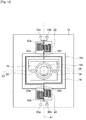
Fig. 1] Fig. 1 is a plan view showing a mirror drive device according to a first embodiment of the present invention. - [
Fig. 2] Fig. 2 is a cross-sectional view along the line II-II ofFig. 1 . - [
Fig. 3] Fig. 3 is a cross-sectional view along the line III-III ofFig. 1 . - [
Fig. 4] Fig. 4 is a cross-sectional view along the line IV-IV ofFig. 1 . - [
Fig. 5] Fig. 5 is a plan view showing a mirror drive device according to a second embodiment of the present invention. - [
Fig. 6] Fig. 6 is a plan view showing a drive coil of a mirror drive device according to the second embodiment. - [
Fig. 7] Fig. 7 is a cross-sectional view along the line VII-VII ofFig. 5 . - [
Fig. 8] Fig. 8 is a perspective view showing a permanent magnet of a mirror drive device according to a second embodiment. - [
Fig. 9] Fig. 9 is a view showing diagrammatically the magnetic field formed by the permanent magnet ofFig. 8 . - [
Fig. 10] Fig. 10 is a partial cross-sectional view showing the movable section of the mirror drive device according to the second embodiment. - [
Fig. 11] Fig. 11 is a cross-sectional view of a mirror drive device according to the second embodiment.Fig. 11(a) shows a cross section along the line XIA-XIA ofFig. 6 andFig. 11(b) shows a cross section along the line XIB-XIB ofFig. 6 . - [
Fig. 12] Fig. 12 is a plan view showing a further example of a drive coil. - [
Fig. 13] Fig. 13 is a view showing a further example of a mirror drive device. - [
Fig. 14] Fig. 14 is a view showing a further example of a mirror drive device. - Embodiments of the present invention are described with reference to the drawings, but these embodiments merely represent examples given by way of explanation of the present invention and the present invention is not intended to be restricted to the following content. In the description, identical elements or elements having the same function are given the same reference symbols and repetition of description is dispensed with.
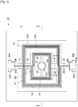
- As shown in
Fig. 1 andFig. 2 , amirror drive device 1A according to the first embodiment comprises apermanent magnet 10, fixed frame (support section) 12, movable frame (movable section) 14 andmirror 16. - The
permanent magnet 10 is a flat plate presenting a rectangular shape. Thepermanent magnet 10 has a pair ofmain faces permanent magnet 10 forms a magnetic field around the movable frame 14 (around the drive coils 18, 20, to be described). The thickness of thepermanent magnet 10 may be set at for example about 2 mm to 3 mm. - The fixed
frame 12 is a frame presenting a rectangular shape. The fixedframe 12 is arranged on themain face 10a of thepermanent magnet 10. The thickness of the fixedframe 12 may be set at for example about 250 µm to 300 µm. - The
movable frame 14 is arranged within the aperture of the fixedframe 12. Themovable frame 14 comprises anoutside section 14a that is positioned on the outside, aninside section 14b that is positioned inside theoutside section 14a, and amirror arrangement section 14c whereby themirror 16 is arranged and positioned within theinside section 14b. - The
outside section 14a and theinside section 14b are frames of flat plate shape that present a rectangular shape. Theoutside section 14a is separated from thepermanent magnet 10 and the fixedframe 12. Theoutside section 14a is provided with a main face S1 that faces the opposite side to that of thepermanent magnet 10. Theoutside section 14a is mounted in rotatable fashion with respect to the fixedframe 12, by means of a pair of torsion bars (linking members) 22 that extend on the same straight line. The torsion bars 22 may be of linear shape, or may be of serpentine shape. - A
drive coil 18 is arranged on the side of the main face S1 of theoutside section 14a. Thedrive coil 18 is coiled a plurality of times in spiral fashion as seen from the direction orthogonal with respect to the main face S1 (surface of the mirror 16). One end of thedrive coil 18 is positioned outside thedrive coil 18, while the other end of thedrive coil 18 is positioned within thedrive coil 18. One end of an external-connection conductor 28a is electrically connected with the outside terminal of thedrive coil 18. One end of an external-connection conductor 28b is electrically connected with the inside terminal of thedrive coil 18. - The external-
connection conductors outside section 14a, through thetorsion bar 22, as far as the fixedframe 12. The other ends of the external-connection conductors electrodes frame 12. Theelectrodes connection conductor 28b intersects thedrive coil 18 in three-dimensional fashion, being arranged so as to pass above thedrive coil 18. - The
inside section 14b is separated from theoutside section 14a. Theinside section 14b is provided with a main face S2 facing the opposite side to that of thepermanent magnet 10. Theinside section 14b is mounted in rotatable fashion with respect to theoutside section 14a, by means of a pair oftorsion bars 24 that extend on the same straight line as thetorsion bar 22. The torsion bars 24 may present a linear shape or a serpentine shape. - The
drive coil 20 is arranged on the side of the main face S2 of theinside section 14b. Thedrive coil 20 is coiled as a plurality of turns in spiral fashion as seen from the direction orthogonal with respect to the main face S2 (surface of the mirror 16). One end of thedrive coil 20 is positioned outside thedrive coil 20, while the other end of thedrive coil 20 is positioned within thedrive coil 20. One end of an external-connection conductor 32a is electrically connected with the outside terminal of thedrive coil 20. One end of an external-connection conductor 32b is electrically connected with the inside terminal of thedrive coil 20. - The external-
connection conductors inside section 14b as far as thetorsion bar 22 and extend as far as the fixedframe 12 through theoutside section 14a andtorsion bar 22. The other ends of the external-connection conductors electrodes frame 12. Theelectrodes connection conductor 32a three-dimensionally intersects thedrive coil 18, being arranged to pass over thedrive coil 18. The external-connection conductor 32b three-dimensionally intersects the drive coils 18 and 20, being arranged to pass over the drive coils 18 and 20. - A
mirror arrangement section 14c is a disc presenting a circular shape. Themirror arrangement section 14c has a main face S3 facing the opposite side to that of thepermanent magnet 10. Themirror arrangement section 14c is mounted on theinside section 14b by means of a pair of support beams 26 that extend on the same straight line. By linking themirror arrangement section 14c with theinside section 14b by means of the support beams 26, it becomes difficult for Joule heating that is generated in the drive coils 18, 20 to be transmitted to themirror arrangement section 14c; deformation of themirror arrangement section 14c can thereby be suppressed. In the first embodiment, the direction facing the support beams 26 intersects the direction facing the torsion bars 22, 24. - The
mirror 16 is arranged on the main face S3 of themirror arrangement section 14c. Themirror 16 is an optical reflecting film constituted of a thin metal film. The metallic material used in themirror 16 may be for example aluminum (Al), gold (Au) or silver (Ag). - Next, the detailed construction of the drive coils 18, 20 is described below. The drive coils 18 and 20 both have the same construction, so hereinbelow the
drive coil 18 is described and description of thedrive coil 20 is dispensed with. - As shown in
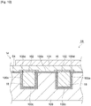
Fig. 3 andFig. 4 , theoutside section 14a is provided with asubstrate 100, adrive coil 18, coveringlayer 102 and an insulatinglayer 104. Thesubstrate 100 has agroove 100a that presents a shape corresponding to thedrive coil 18. Specifically, thegroove 100a extends in spiral fashion as seen from the side of the main face S4 of thesubstrate 100. Such agroove 100a may be formed by for example forming a mask of a prescribed pattern on the surface of the flat plate-shapedsubstrate 100 and then etching thesubstrate 100 through this mask. Thesubstrate 100 is constituted for example of Si (silicon). The thickness of thesubstrate 100 may be set for example at about 20 µm to 60 µm. - An insulating
layer 100b is arranged on the inside wall surface of thegroove 100a and the main face S4 of thesubstrate 100. The insulatinglayer 100b is a thermal oxide film obtained by thermal oxidation of thesubstrate 100. The insulatinglayer 100b is constituted for example of SiO2 (silicon oxide). Theseed layer 100c is arranged on the inside wall face of thegroove 100a. Specifically, theseed layer 100c is arranged between the insulatinglayer 100b and thedrive coil 18. Theseed layer 100c is obtained by sputtering fine metallic material having adhesion for the metallic material constituting thedrive coil 18 onto the substrate 100 (insulatinglayer 100b). The metallic material constituting theseed layer 100c may be for example TiN. - The metallic material constituting the
drive coil 18 is arranged within thegroove 100a and on theseed layer 100c. Thedrive coil 18 is obtained by embedding this metallic material on theseed layer 100c by the damascene process. As the method of embedding this metallic material in thegroove 100a, there may be mentioned by way of example plating or sputtering or CVD. - After arranging this metallic material in the
groove 100a, the main face S4 is flattened by electrochemical polishing. In this flattening step, theboundary portion 100d where thedrive coil 18 contacts theseed layer 100c may be locally reduced in thickness by for example the potential difference generated between thedrive coil 18 and theseed layer 100c. As the metallic material in question, there may be mentioned by way of example Cu or Au. The thickness of thedrive coil 18 is set at for example about 5 µm to 10 µm. - The
covering layer 102 extends as far as the main face S4 so as to cover the aperture of thegroove 100a. Specifically, thecovering layer 102 covers the entire surface of thedrive coil 18 on the side of the main faces S1, S4 and covers the portion of thesubstrate 100 surrounding thegroove 100a, as seen from the direction orthogonal to the main faces S1, S4 (i.e. the surface of the mirror 16). Thecovering layer 102 is obtained by depositing metallic material on the entire upper surface of thesubstrate 100 by for example a sputtering process or CVD process and then patterning. - The metallic material constituting the
covering layer 102 has the function of suppressing diffusion of the metallic material constituting thedrive coil 18. As the metallic material constituting thecovering layer 102, there may be mentioned by way of example Al or Al-containing alloy. As the Al-containing alloy, there may be mentioned Al-Si alloy, Al-Cu alloy or Al-Si-Cu alloy. The constituent ratio of the Al-Si alloy may be for example Al 99%,Si 1%. The constituent ratio of the Al-Cu alloy may be for example Al 99%,Cu 1%. The constituent ratio of the Al-Si-Cu alloy may be for example Al 98%,Si 1%,Cu 1%. The thickness of thecovering layer 102 may be set for example at about 1 µm. - The insulating
layer 104 is arranged so as to cover thesubstrate 100 and thecovering layer 102. As the material constituting the insulatinglayer 104, there may be mentioned by way of example SiO2, SiN or TEOS. The external-connection conductors layer 104. Specifically, theexternal connection conductors drive coil 18 by the insulatinglayer 104 and thecovering layer 102. - In the first embodiment as described above, the
covering layer 102 is constituted by a metallic material that suppresses diffusion of the metallic material constituting the drive coils 18, 20 and extends as far as the main face S4 so as to cover the aperture of thegroove 100a. This therefore makes it difficult for the metallic material constituting the drive coils 18, 20 to diffuse into the insulatinglayer 104 and thereby prevents short-circuiting from occurring between adjacent wirings of the drive coils 18, 20 and between the drive coils 18, 20 and the external-connection conductors mirror drive device 1A with a large range of movement of themirror 16 can be obtained. - Incidentally, in the flattening step, if the boundary portion where the drive coils contact the seed layer was locally reduced in thickness, in the case of a conventional mirror drive device, in which the
covering layer 102 is absent, the distance between the drive coils and the external-connection conductors that are formed on the insulating layer covering the drive coils was small and, in particular, short-circuiting was liable to occur. However, with the first embodiment, thecovering layer 102 extends not only to the surface of the drive coils 18, 20 but also as far as the main face S4 so as to cover the aperture of thegroove 100a. As a result, even if theboundary portion 100d is locally reduced in thickness, conduction faults due to short-circuiting can be prevented. - In the first embodiment, the metallic material constituting the drive coils 18, 20 is Cu or Au. Even when the drive coils 18, 20 are constituted using Cu or Au, which, although their electrical resistance ratio is low, are materials which are comparatively prone to diffusion, diffusion of these materials can be suppressed by the
covering layer 102. Consequently, the electrical resistance ratio of the drive coils 18, 20 can be lowered, while still preventing occurrence of short-circuiting. - In the first embodiment, the
seed layer 100c having adhesion with respect to the metallic material constituting the drive coils 18, 20 is arranged between the insulatinglayer 100b and the drive coils 18, 20. Consequently, the metallic material constituting the drive coils 18, 20 can be grown on theseed layer 100c using an electroplating process. - Next, a
mirror drive device 1B according to the second embodiment will be described. As shown inFig. 5 to Fig. 8 , themirror drive device 1B comprises apermanent magnet 10, a fixed frame (support section) 12, amovable section 14 and amirror 16. - As shown in
Fig. 7 andFig. 8 , thepermanent magnet 10 is a flat plate presenting a rectangular shape. Thepermanent magnet 10 is arranged below themovable section 14. Thepermanent magnet 10 has a pair ofmain faces permanent magnet 10 forms a magnetic field around the movable frame 14 (around thedrive coil 18, to be described). - The
permanent magnet 10 is provided with a firstmagnetic section 10A, a secondmagnetic section 10B and a thirdmagnetic section 10C. As shown inFig. 8 , the firstmagnetic section 10A and the secondmagnetic section 10B are respectively arranged, in thepermanent magnet 10, at one end side and the other end side in the diagonal direction of the bottom face of thepermanent magnet 10. The thirdmagnetic section 10C is arranged between the firstmagnetic section 10A and the secondmagnetic section 10B. Theboundary face 10D of the firstmagnetic section 10A and the thirdmagnetic section 10C and theboundary face 10E of the thirdmagnetic section 10C and the secondmagnetic section 10B are parallel with the Z axis and constitute a plane that orthogonally intersects both the X-axis and Y-axis. - The first
magnetic section 10A has amagnetic pole 10A1 of a first polarity and amagnetic pole 10A2 of a second polarity different from the first polarity. The secondmagnetic section 10B has amagnetic pole 10B1 of the first polarity and amagnetic pole 10B2 of the second polarity. The thirdmagnetic section 10C has amagnetic pole 10C1 of the first polarity and amagnetic pole 10C2 of the second polarity. Themagnetic pole 10C1 is arranged in the thirdmagnetic section 10C on the side facing the firstmagnetic section 10A. Themagnetic pole 10C2 is arranged in the thirdmagnetic section 10C on the side facing the secondmagnetic section 10B. In the second embodiment, the first polarity is the polarity of an S pole and the second polarity is the polarity of an N pole. Contrariwise, it would be possible for the first polarity to be the polarity of an N pole, while the second polarity is the polarity of an S pole. - The first
magnetic section 10A, thirdmagnetic section 10C and secondmagnetic section 10B constitute a Halbach array. Specifically, in the firstmagnetic section 10A, the first-polarity pole 10A1 and the second-polarity pole 10A2 are oppositely arranged in the Z axis direction. In the thirdmagnetic section 10C adjacent to the firstmagnetic section 10A, the first-polarity pole 10C1 and the second-polarity pole 10C2 face each other in the direction parallel with the X and Y directions. In the secondmagnetic section 10B that is positioned on the opposite side of the firstmagnetic section 10A in relation to the thirdmagnetic section 10C and adjacent to the thirdmagnetic section 10C, the first-polarity pole 10B1 and the second-polarity pole 10B2 face each other in the Z axis direction. In this way, the facing directions of the two polarities that are respectively present in the adjacent pairs of the firstmagnetic section 10A, thirdmagnetic section 10C and secondmagnetic section 10B are in mutually perpendicular directions. - The direction of the magnetic field formed by the
permanent magnet 10 makes a prescribed angle (described in detail later). As shown inFig. 9 , the magnetic field F is formed along the planar direction of thesurface 14s of themovable section 14, to be described. The thickness of thepermanent magnet 10 can be set at for example about 2 mm to 3 mm. - The fixed
frame 12 is a frame that presents a rectangular shape. The fixedframe 12 is arranged on themain face 10a of thepermanent magnet 10. The thickness of the fixedframe 12 may be set at for example about 250 µm to 300 µm. - The
movable section 14 is positioned within the aperture of the fixedframe 12. Themovable section 14 is of flat plate form, presenting a circular shape. Herein, the expression "circular shape" includes a true circle or ellipse. In the second embodiment, themovable section 14 presents a true circular shape. Themovable section 14 is swingably supported with respect to the fixedframe 12, by means of a pair of torsion bars 22. Specifically, themovable section 14 is supported in such a way that it can perform reciprocating rotational movement with respect to the fixedframe 12, by means of the pair of torsion bars 22. The pair oftorsion bars 22 is linked with the fixedframe 12 and themovable section 14. The pair oftorsion bars 22 is arranged in a position sandwiching the movable section 7 from both sides. - The pair of
torsion bars 22 are arranged in linear fashion. In the second embodiment, the pair oftorsion bars 22 extends along the straight line L shown inFig. 9 . The straight line L contains at least the pair oftorsion bars 22,movable section 14 and the two connection locations C, and links the two connection locations C. Consequently, the straight line L behaves as the axis of swinging motion of themovable section 14. The direction of the magnetic field F shown inFig. 9 makes an angle of about 45° with respect to the straight line L. - The torsion bars are not restricted to being of linear form and could be for example of serpentine shape, having a straight portion and a plurality of bent-back portions that alternately link both ends of these straight portions. In such an arrangement, the connection location of the torsion bars and the fixed
frame 12 and the connection location of the torsion bars and themovable section 14 may be positioned on the same straight line, or may not be positioned on the same straight line. If these locations are not positioned on the same straight line, the direction that makes a prescribed angle with the direction of the magnetic field F may be either of the direction extending along the axis of swinging or the direction of extension of the torsion bars (linking members). - The
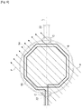
mirror 16 is arranged on thesurface 14s of themovable section 14. In the second embodiment, as shown inFig. 5 , themirror 16 is circular in shape. Themirror 16 is a light-reflecting film constituted by a thin metallic film. The metallic material employed in themirror 16 may be for example aluminum (Al), gold (Au) or silver (Ag). - The
drive coil 18 is arranged on themovable section 14. Thedrive coil 18 is arranged below themirror 16 and is embedded in the form of a planar helical winding in themovable section 14. Thedrive coil 18 is arranged in a position on the inside of themirror 16 i.e. covered (hidden) by themirror 16, as seen from the direction orthogonal to thesurface 14s (main face S4 of thesubstrate 100, to be described) of themovable section 14. In other words, thedrive coil 18 is hidden by themirror 16, as seen from the direction orthogonal to thesurface 14s of themovable section 14. As shown inFig. 6 , thedrive coil 18 presents a polygonal shape, more specifically, an octagonal shape, as seen from the direction orthogonal to thesurface 14s of themovable section 14. - As shown in
Fig. 10 , thedrive coil 18 of themirror drive device 1B according to the second embodiment chiefly differs from thedrive coil 18 of themirror drive device 1A according to the first embodiment in that, instead of the external-connection conductors mirror 9 is arranged on the insulatinglayer 104. - As shown in
Fig. 6 , one end of the external-connection conductor 28a is electrically connected with one end of thedrive coil 18. The other end of thedrive coil 18 is electrically connected with one end of the external-connection conductor 28b. The external-connection conductors torsion bar 22, extending as far as the fixedframe 12. The other ends of the external-connection conductors electrodes frame 12. Theelectrodes - As shown in
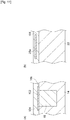
Fig. 11(a) , in the vicinity of the connection locations C of the torsion bars 22 and themovable section 14, the drive coil 18 (wiring) is formed by damascene wiring whose material is Cu or Au. Also, although not shown, at the location of connection of the torsion bars 22 and the fixedframe 12, wiring connecting the external-connection conductors electrodes Fig. 11(b) in the vicinity of the middle of the torsion bars 22, the external-connection conductor 28a is formed of material such as for example Al or Al-containing alloy i.e. material that is not as easily plastically deformed as the Cu that forms thedrive coil 18. The other end of thedrive coil 18 and one end of the external-connection conductor 28a are electrically connected by a connecting section, not shown. As shown inFig. 11(a) and (b) , thedrive coil 18 and the external-connection conductor 28a have different height positions. Consequently, thedrive coil 18 and the external-connection conductor 28a are connected by the aforementioned connecting section, which extends in a direction orthogonal to thesurface 14s of themovable section 14. While inFig. 11(b) , the external-connection conductor 28a is shown, the external-connection conductor 28b has the same construction. - As described above, the
mirror drive device 1B according to the second embodiment presents the same actions and beneficial effects as themirror drive device 1A according to the first embodiment. Consequently, with themirror drive device 1B according to the second embodiment, short-circuiting between thedrive coil 18 and themirror 16 is prevented, so conduction faults due to short-circuiting can be eliminated. - In the second embodiment, the
drive coil 18 is arranged on the inside of themirror 16, as seen from the direction orthogonal to the main face S4 of thesubstrate 100 and below themirror 16. In the conventional construction, in which the drive coil is arranged around the mirror, if miniaturization is to be achieved, the mirror area has to be reduced. In contrast, in the case of themirror drive device 1B, by adopting the construction thereof described above, miniaturization can be achieved while preserving the area of themirror 16. - In the second embodiment, the external-
connection conductors mirror drive device 1B, Al or Al-containing alloy, which is less subject to plastic deformation than the material (Cu or Au) forming thedrive coil 18, is employed for the external-connection conductors connection conductors mirror drive device 1B, the mechanical strength of the torsion bars 22 can be preserved, and for example failure of the external-connection conductors - Regarding the construction of the external-
connection conductors frame 12 and the torsion bars 22 and themovable section 14, in a further aspect, according to the second embodiment, there are provided: a supporting section, torsion bars extending on the same straight line, a movable section supported in swingable fashion with respect to the supporting section, by means of the torsion bars, and a mirror arranged on the movable section, an electrical drive element (for example a drive coil or electrode of a piezoelectric body) arranged on the movable section, and wiring connecting the electrical drive element, arranged on the torsion bars along the direction of extension of these torsion bars; wherein the wiring in the vicinity of the connection location of the torsion bars and the supporting section and the vicinity of the connection location of the torsion bars and the movable section is constituted as damascene wiring by a first metallic material constituted by Cu arranged in a groove: thus the mirror drive device can be characterized as a mirror drive device wherein the wiring in the vicinity of the middle of the torsion bars is constituted by a second metallic material that is less subject to plastic deformation than the first metallic material. - While embodiments of the present invention have been described in detail above, the present invention is not restricted to the aforementioned embodiments. For example, in the embodiments described above,
mirror drive devices - In the second embodiment, the
movable section 14 was described as being of circular shape, but the shape of themovable section 14 is not restricted to this. Specifically, themovable section 14 may present an octagonal shape (seeFig. 12(a) ) or may present a rectangular shape (seeFig. 12(b) ). Furthermore, the movable section may present a hexagonal shape. In other words, the movable section may have any shape. - In the second embodiment, the
mirror 16 was described as being of circular shape, but the shape of themirror 16 is not restricted to this. Specifically, themirror 16 may present an octagonal shape corresponding to the shape of the movable section 14 (seeFig. 12(a) ), or may present a rectangular shape corresponding to the shape of the movable section 14 (seeFig. 12(b) ). Also, the mirror may present a shape different from that of the movable section. In other words, the mirror may have any shape. - In the second embodiment, an example was described in which the
drive coil 18 has a construction presenting an octagonal shape as seen from the direction orthogonal to thesurface 14s of themovable section 14, but the shape of thedrive coil 18 is not restricted to this. As shown inFig. 12(b) , thedrive coil 18 could have a rectangular shape. Also, the number of turns of the drive coil may be suitably set in accordance with the design of themirror drive device 1B. - In the second embodiment, an example was described in which the external-
connection conductors layer 104, but the external-connection conductors layer 104. - In the second embodiment, the external-
connection conductors drive coil 18 extended as far as theelectrodes connection conductor 28a to be arranged in one of the torsion bars 22 and for the external-connection conductor 28b to be arranged in the other of the torsion bars 22. In other words, a construction could be adopted in which the external-connection conductors electrodes torsion bars 22 is broken, one or other of the external-connection conductors connection conductors connection conductors - In the second embodiment, an example was described of an arrangement in which the
entire drive coil 18 was arranged on the inside of themirror 16, but it would also be possible to arrange part of thedrive coil 18 on the inside of themirror 16. - In the above embodiments,
linear torsion bars 22 were described by way of example, but the construction of the torsion bars is not restricted to this, and it would be possible for example to make these of serpentine shape.Fig. 13 andFig. 14 show an example oftorsion bars 22 of serpentine shape. - While in the above embodiments an example was described of a one-dimensional drive type device, in which the
mirror 16 was driven one-dimensionally by swinging themovable section 14 about the direction of extension of the torsion bars 22 (linked members) or about the direction of extension of the swinging axis, by linking the fixedframe 12 andmovable section 14 by means of the pair oftorsion bars 22, it would also be possible for the mirror drive device to be constituted as a two-dimensional type drive device, in which themirror 16 is driven in two-dimensional fashion.Fig. 13 andFig. 14 show an example of such a two-dimensional type drive device. - The construction of the mirror drive device shown in
Fig. 13 andFig. 14 will now be described, focusing on the differences with regard to themirror drive device 1A according to the first embodiment. In the mirror drive device shown inFig. 13 , just as in the case of themirror drive device 1A shown inFig. 1 , both of the drive coils 18, 20 surround themirror 16. In the case of the mirror drive device shown inFig. 14 , thedrive coil 18 surrounds themirror 16 in the same way as themirror drive device 1A according to the first embodiment; in contrast thedrive coil 20 is arranged on the inside of themirror 16 in the same way as themirror drive device 1B according to the second embodiment. - A pair of
concave sections 12a are formed on a pair of inside edges, of the four inside edges of the fixedframe 12. The pair ofconcave sections 12a respectively accommodatetorsion bars 22 presenting a serpentine shape. Theoutside section 14a is swingable about a straight line A1 that extends along the direction of opposition of the pair ofconcave sections 12a. - The
inside section 14b is mounted on theoutside section 14a by means of a pair oftorsion bars 24 that extend orthogonally with respect to the torsion bars 22. Specifically, theinside section 14b is swingable about a straight line A2 that is orthogonal to the straight line A1. InFig. 13 , themirror arrangement section 14c is directly fixed to the inside of theinside section 14b without interposition of a supportingbeam 26. InFig. 14 , theinside section 14b presents a circular shape and also serves as themirror arrangement section 14c. - With the mirror drive device described above, the
outside section 14a is swingable about the straight line A1 and theinside section 14b (mirror arrangement section 14c) is swingable about the straight line A2, so themirror 16 can be driven two-dimensionally. The direction of the magnetic field F may have a prescribed angle with respect to the two axes of swinging motion, as shown inFig. 9 . In this case, it is unnecessary to provide a magnet for each swinging axis. - 1A, 1B... Mirror drive devices, 10... Permanent magnet, 12... Fixed frame, 14... Movable section, 16... Mirror, 18, 20... Drive coils, 22, 24... Torsion bars, 28a, 28b, 32a, 32b... External-connection conductors, 100... Substrate, 100a... Groove, 100b... Insulating layer, 100c... Seed layer, 102... Covering layer, 104... Insulating layer, S1 to S4... Main faces.
Claims (7)
- A mirror drive device (1A) comprising:a support section (12);a movable section (14) that is supported, by means of a linking member, in rotatable fashion with respect to said support section (12);a mirror (16) that is arranged on the surface of said movable section (14);and a magnet (10) that forms a magnetic field around said movable section (14);wherein said movable section (14) is provided with:a substrate including a main face and a groove (100a) positioned on the side of said main face and extending in spiral fashion as seen from a direction intersecting said main face;a drive coil (18) constituted by a first metallic material arranged in said groove (100a) and that is coiled in spiral fashion as seen from a direction orthogonal to the main face;a covering layer constituted by a second metallic material that suppresses diffusion of said first metallic material and extends as far as said main face so as to cover the aperture of said groove;and a first insulating layer (100b) arranged on said main face and said covering layer,wherein one end of an external-connection conductor is electrically connected with an inside terminal of said drive coil,and the other end of said external-connection conductor extends to outside said drive coil,said external-connection conductor three-dimensionally intersects said drive coil (18), through said first insulating layer (100b).
- The mirror drive device (1A) as claimed in claim 1 wherein said first metallic material is Cu or Au.
- The mirror drive device (1A) as claimed in claim 1 or 2 wherein said second metallic material is Al or an Al-containing alloy.
- The mirror drive device (1A) as claimed in any of claims 1 to 3 wherein said substrate has a second insulating layer arranged along said main face and the inside wall face of said groove.
- The mirror drive device (1A) as claimed in claim 4 wherein said substrate is made of silicon and said second insulating layer is made of silicon oxide produced by thermal oxidation of silicon.
- The mirror drive device (1A) as claimed in claim 4 or 5 wherein a seed layer is arranged between said second insulating layer and said first metallic material.
- The mirror drive device (1A) as claimed in claim 6 wherein said seed layer is constituted of TiN.
Applications Claiming Priority (4)
| Application Number | Priority Date | Filing Date | Title |
|---|---|---|---|
| JP2013003345A JP2015227899A (en) | 2013-01-11 | 2013-01-11 | Mirror driving device |
| JP2013160522A JP6175305B2 (en) | 2013-08-01 | 2013-08-01 | Mirror drive device |
| JP2013160589A JP2017060205A (en) | 2013-08-01 | 2013-08-01 | Mirror device |
| PCT/JP2013/083359 WO2014109170A1 (en) | 2013-01-11 | 2013-12-12 | Mirror driving device |
Publications (3)
| Publication Number | Publication Date |
|---|---|
| EP2944998A1 EP2944998A1 (en) | 2015-11-18 |
| EP2944998A4 EP2944998A4 (en) | 2016-09-28 |
| EP2944998B1 true EP2944998B1 (en) | 2018-10-03 |
Family
ID=51166831
Family Applications (1)
| Application Number | Title | Priority Date | Filing Date |
|---|---|---|---|
| EP13871072.8A Not-in-force EP2944998B1 (en) | 2013-01-11 | 2013-12-12 | Mirror driving device |
Country Status (4)
| Country | Link |
|---|---|
| US (1) | US10103613B2 (en) |
| EP (1) | EP2944998B1 (en) |
| CN (1) | CN105934698B (en) |
| WO (1) | WO2014109170A1 (en) |
Cited By (1)
| Publication number | Priority date | Publication date | Assignee | Title |
|---|---|---|---|---|
| DE102021204467A1 (en) | 2021-05-04 | 2022-11-10 | Robert Bosch Gesellschaft mit beschränkter Haftung | Micromechanical vibration system |
Families Citing this family (27)
| Publication number | Priority date | Publication date | Assignee | Title |
|---|---|---|---|---|
| EP2944998B1 (en) * | 2013-01-11 | 2018-10-03 | Intel Corporation | Mirror driving device |
| DE102015217935A1 (en) * | 2015-09-18 | 2017-03-23 | Robert Bosch Gmbh | Micromechanical actuator device and method for tilting a micromechanical actuator device |
| JP6691784B2 (en) * | 2016-01-21 | 2020-05-13 | 浜松ホトニクス株式会社 | Actuator device |
| JP6696777B2 (en) * | 2016-01-21 | 2020-05-20 | 浜松ホトニクス株式会社 | Actuator device |
| US10162016B2 (en) * | 2016-03-08 | 2018-12-25 | Texas Instruments Incorporated | Reduction of magnetic sensor component variation due to magnetic materials through the application of magnetic field |
| JP2017181715A (en) * | 2016-03-30 | 2017-10-05 | セイコーエプソン株式会社 | Optical scanner component, optical scanner, manufacturing method of the same, image display unit, and head mount display |
| CN105676447A (en) * | 2016-04-05 | 2016-06-15 | 合肥芯福传感器技术有限公司 | Voice-coil-motor-driven scanning micro-mirror |
| JP6761204B2 (en) * | 2016-06-27 | 2020-09-23 | 株式会社リコー | Optical deflector, optical scanning device, image projection device, failure detection method, optical writing device, image forming device, object recognition device, moving body, non-moving body and optical interference tomography |
| JP6694355B2 (en) * | 2016-09-01 | 2020-05-13 | 浜松ホトニクス株式会社 | Movable diffraction grating, manufacturing method thereof, and external resonator type laser module |
| DE102016220514A1 (en) * | 2016-10-19 | 2018-04-19 | Robert Bosch Gmbh | Micromechanical component and production method for a micromechanical component |
| EP4198605A1 (en) * | 2017-02-28 | 2023-06-21 | Hamamatsu Photonics K.K. | Optical module |
| JP6924090B2 (en) | 2017-07-21 | 2021-08-25 | 浜松ホトニクス株式会社 | Actuator device |
| JP7015653B2 (en) * | 2017-08-10 | 2022-02-03 | 浜松ホトニクス株式会社 | Optical module and manufacturing method of optical module |
| JP2019061181A (en) * | 2017-09-27 | 2019-04-18 | 日本信号株式会社 | Actuator |
| DE102017220413A1 (en) * | 2017-11-16 | 2019-05-16 | Robert Bosch Gmbh | Micromechanical component and production method for a micromechanical component |
| JP6585147B2 (en) * | 2017-12-01 | 2019-10-02 | 浜松ホトニクス株式会社 | Actuator device |
| EP3719558B1 (en) * | 2017-12-01 | 2024-03-20 | Hamamatsu Photonics K.K. | Actuator device |
| JP7137321B2 (en) * | 2018-02-28 | 2022-09-14 | 浜松ホトニクス株式会社 | Movable diffraction grating, external cavity laser module, method for manufacturing movable diffraction grating |
| EP3876265B1 (en) * | 2018-10-31 | 2023-07-12 | Hamamatsu Photonics K.K. | Damascene interconnect structure, actuator device, and method of manufacturing damascene interconnect structure |
| JPWO2020110747A1 (en) * | 2018-11-30 | 2021-09-27 | パイオニア株式会社 | Drive device |
| JP7313831B2 (en) * | 2019-01-30 | 2023-07-25 | 浜松ホトニクス株式会社 | optical module |
| CN111830701B (en) * | 2019-04-19 | 2022-02-15 | 华为技术有限公司 | Electromagnetic micromirror and laser device |
| US11424374B2 (en) * | 2019-04-19 | 2022-08-23 | Tdk Taiwan Corp. | Camera module optical system |
| US11604347B2 (en) * | 2019-08-18 | 2023-03-14 | Apple Inc. | Force-balanced micromirror with electromagnetic actuation |
| JP6960978B2 (en) * | 2019-12-02 | 2021-11-05 | 三菱電機株式会社 | Mirror device |
| JP7292469B2 (en) * | 2020-04-23 | 2023-06-16 | 浜松ホトニクス株式会社 | Actuator device |
| CN115718399B (en) * | 2022-11-17 | 2023-11-07 | 东莞市维斗科技股份有限公司 | Novel vibrating mirror |
Family Cites Families (9)
| Publication number | Priority date | Publication date | Assignee | Title |
|---|---|---|---|---|
| US4421381A (en) * | 1980-04-04 | 1983-12-20 | Yokogawa Hokushin Electric Corp. | Mechanical vibrating element |
| JP2987750B2 (en) * | 1995-05-26 | 1999-12-06 | 日本信号株式会社 | Planar type electromagnetic actuator |
| JP3926552B2 (en) * | 2000-10-25 | 2007-06-06 | 日本信号株式会社 | Actuator |
| KR100908120B1 (en) * | 2006-11-01 | 2009-07-16 | 삼성전기주식회사 | Electromagnetic micro actuator |
| JP2010169948A (en) | 2009-01-23 | 2010-08-05 | Sumitomo Precision Prod Co Ltd | Rocking mirror for optical scanner, rocking state detector, and optical scanner |
| EP2689283A1 (en) | 2011-03-25 | 2014-01-29 | Lemoptix SA | A reflective device |
| US8973250B2 (en) * | 2011-06-20 | 2015-03-10 | International Business Machines Corporation | Methods of manufacturing a micro-electro-mechanical system (MEMS) structure |
| JP6044943B2 (en) * | 2011-10-25 | 2016-12-14 | インテル・コーポレーション | Actuator |
| EP2944998B1 (en) * | 2013-01-11 | 2018-10-03 | Intel Corporation | Mirror driving device |
-
2013
- 2013-12-12 EP EP13871072.8A patent/EP2944998B1/en not_active Not-in-force
- 2013-12-12 CN CN201380074565.8A patent/CN105934698B/en active Active
- 2013-12-12 US US14/760,637 patent/US10103613B2/en active Active
- 2013-12-12 WO PCT/JP2013/083359 patent/WO2014109170A1/en active Application Filing
Non-Patent Citations (1)
| Title |
|---|
| None * |
Cited By (1)
| Publication number | Priority date | Publication date | Assignee | Title |
|---|---|---|---|---|
| DE102021204467A1 (en) | 2021-05-04 | 2022-11-10 | Robert Bosch Gesellschaft mit beschränkter Haftung | Micromechanical vibration system |
Also Published As
| Publication number | Publication date |
|---|---|
| EP2944998A1 (en) | 2015-11-18 |
| EP2944998A4 (en) | 2016-09-28 |
| WO2014109170A1 (en) | 2014-07-17 |
| CN105934698A (en) | 2016-09-07 |
| CN105934698B (en) | 2019-04-16 |
| US20160105090A1 (en) | 2016-04-14 |
| US10103613B2 (en) | 2018-10-16 |
Similar Documents
| Publication | Publication Date | Title |
|---|---|---|
| EP2944998B1 (en) | Mirror driving device | |
| JP6250323B2 (en) | Mirror drive device | |
| US10394017B2 (en) | Actuator device and mirror drive device | |
| US11952265B2 (en) | Actuator device | |
| JP6479354B2 (en) | Mirror drive device and manufacturing method thereof | |
| US10759655B2 (en) | Actuator device | |
| JP2008122955A (en) | Electromagnetic micro-actuator | |
| US5966009A (en) | Electromagnetic actuator and manufacturing method therefor | |
| JP6175305B2 (en) | Mirror drive device | |
| JP6463447B2 (en) | Mirror drive device | |
| JP6084333B1 (en) | Electronic components | |
| EP0836265B1 (en) | Electromagnetic actuator and its manufacture | |
| JP7065146B2 (en) | Actuator device | |
| JP6040032B2 (en) | Electronic components | |
| JP2019074766A (en) | Mirror drive device and manufacturing method of the same |
Legal Events
| Date | Code | Title | Description |
|---|---|---|---|
| PUAI | Public reference made under article 153(3) epc to a published international application that has entered the european phase |
Free format text: ORIGINAL CODE: 0009012 |
|
| 17P | Request for examination filed |
Effective date: 20150814 |
|
| AK | Designated contracting states |
Kind code of ref document: A1 Designated state(s): AL AT BE BG CH CY CZ DE DK EE ES FI FR GB GR HR HU IE IS IT LI LT LU LV MC MK MT NL NO PL PT RO RS SE SI SK SM TR |
|
| AX | Request for extension of the european patent |
Extension state: BA ME |
|
| DAX | Request for extension of the european patent (deleted) | ||
| A4 | Supplementary search report drawn up and despatched |
Effective date: 20160830 |
|
| RIC1 | Information provided on ipc code assigned before grant |
Ipc: B81B 3/00 20060101ALI20160824BHEP Ipc: H02K 3/26 20060101ALI20160824BHEP Ipc: G02B 26/08 20060101ALI20160824BHEP Ipc: G02B 26/10 20060101AFI20160824BHEP Ipc: H02K 33/18 20060101ALI20160824BHEP |
|
| GRAP | Despatch of communication of intention to grant a patent |
Free format text: ORIGINAL CODE: EPIDOSNIGR1 |
|
| INTG | Intention to grant announced |
Effective date: 20180419 |
|
| RIN1 | Information on inventor provided before grant (corrected) |
Inventor name: KIMOTO, MASAKUNI Inventor name: ADACHI, NORIHIDE Inventor name: TAKIMOTO, SADAHARU |
|
| GRAS | Grant fee paid |
Free format text: ORIGINAL CODE: EPIDOSNIGR3 |
|
| GRAA | (expected) grant |
Free format text: ORIGINAL CODE: 0009210 |
|
| AK | Designated contracting states |
Kind code of ref document: B1 Designated state(s): AL AT BE BG CH CY CZ DE DK EE ES FI FR GB GR HR HU IE IS IT LI LT LU LV MC MK MT NL NO PL PT RO RS SE SI SK SM TR |
|
| REG | Reference to a national code |
Ref country code: GB Ref legal event code: FG4D |
|
| REG | Reference to a national code |
Ref country code: CH Ref legal event code: EP Ref country code: AT Ref legal event code: REF Ref document number: 1049234 Country of ref document: AT Kind code of ref document: T Effective date: 20181015 |
|
| REG | Reference to a national code |
Ref country code: IE Ref legal event code: FG4D Ref country code: DE Ref legal event code: R096 Ref document number: 602013044659 Country of ref document: DE |
|
| REG | Reference to a national code |
Ref country code: NL Ref legal event code: FP |
|
| PGFP | Annual fee paid to national office [announced via postgrant information from national office to epo] |
Ref country code: NL Payment date: 20181214 Year of fee payment: 6 |
|
| REG | Reference to a national code |
Ref country code: LT Ref legal event code: MG4D |
|
| PGFP | Annual fee paid to national office [announced via postgrant information from national office to epo] |
Ref country code: FR Payment date: 20181214 Year of fee payment: 6 Ref country code: GB Payment date: 20181214 Year of fee payment: 6 |
|
| REG | Reference to a national code |
Ref country code: AT Ref legal event code: MK05 Ref document number: 1049234 Country of ref document: AT Kind code of ref document: T Effective date: 20181003 |
|
| PG25 | Lapsed in a contracting state [announced via postgrant information from national office to epo] |
Ref country code: CZ Free format text: LAPSE BECAUSE OF FAILURE TO SUBMIT A TRANSLATION OF THE DESCRIPTION OR TO PAY THE FEE WITHIN THE PRESCRIBED TIME-LIMIT Effective date: 20181003 Ref country code: IS Free format text: LAPSE BECAUSE OF FAILURE TO SUBMIT A TRANSLATION OF THE DESCRIPTION OR TO PAY THE FEE WITHIN THE PRESCRIBED TIME-LIMIT Effective date: 20190203 Ref country code: FI Free format text: LAPSE BECAUSE OF FAILURE TO SUBMIT A TRANSLATION OF THE DESCRIPTION OR TO PAY THE FEE WITHIN THE PRESCRIBED TIME-LIMIT Effective date: 20181003 Ref country code: AT Free format text: LAPSE BECAUSE OF FAILURE TO SUBMIT A TRANSLATION OF THE DESCRIPTION OR TO PAY THE FEE WITHIN THE PRESCRIBED TIME-LIMIT Effective date: 20181003 Ref country code: HR Free format text: LAPSE BECAUSE OF FAILURE TO SUBMIT A TRANSLATION OF THE DESCRIPTION OR TO PAY THE FEE WITHIN THE PRESCRIBED TIME-LIMIT Effective date: 20181003 Ref country code: LT Free format text: LAPSE BECAUSE OF FAILURE TO SUBMIT A TRANSLATION OF THE DESCRIPTION OR TO PAY THE FEE WITHIN THE PRESCRIBED TIME-LIMIT Effective date: 20181003 Ref country code: NO Free format text: LAPSE BECAUSE OF FAILURE TO SUBMIT A TRANSLATION OF THE DESCRIPTION OR TO PAY THE FEE WITHIN THE PRESCRIBED TIME-LIMIT Effective date: 20190103 Ref country code: LV Free format text: LAPSE BECAUSE OF FAILURE TO SUBMIT A TRANSLATION OF THE DESCRIPTION OR TO PAY THE FEE WITHIN THE PRESCRIBED TIME-LIMIT Effective date: 20181003 Ref country code: ES Free format text: LAPSE BECAUSE OF FAILURE TO SUBMIT A TRANSLATION OF THE DESCRIPTION OR TO PAY THE FEE WITHIN THE PRESCRIBED TIME-LIMIT Effective date: 20181003 Ref country code: PL Free format text: LAPSE BECAUSE OF FAILURE TO SUBMIT A TRANSLATION OF THE DESCRIPTION OR TO PAY THE FEE WITHIN THE PRESCRIBED TIME-LIMIT Effective date: 20181003 Ref country code: BG Free format text: LAPSE BECAUSE OF FAILURE TO SUBMIT A TRANSLATION OF THE DESCRIPTION OR TO PAY THE FEE WITHIN THE PRESCRIBED TIME-LIMIT Effective date: 20190103 |
|
| PGFP | Annual fee paid to national office [announced via postgrant information from national office to epo] |
Ref country code: DE Payment date: 20181214 Year of fee payment: 6 |
|
| PG25 | Lapsed in a contracting state [announced via postgrant information from national office to epo] |
Ref country code: AL Free format text: LAPSE BECAUSE OF FAILURE TO SUBMIT A TRANSLATION OF THE DESCRIPTION OR TO PAY THE FEE WITHIN THE PRESCRIBED TIME-LIMIT Effective date: 20181003 Ref country code: PT Free format text: LAPSE BECAUSE OF FAILURE TO SUBMIT A TRANSLATION OF THE DESCRIPTION OR TO PAY THE FEE WITHIN THE PRESCRIBED TIME-LIMIT Effective date: 20190203 Ref country code: SE Free format text: LAPSE BECAUSE OF FAILURE TO SUBMIT A TRANSLATION OF THE DESCRIPTION OR TO PAY THE FEE WITHIN THE PRESCRIBED TIME-LIMIT Effective date: 20181003 Ref country code: GR Free format text: LAPSE BECAUSE OF FAILURE TO SUBMIT A TRANSLATION OF THE DESCRIPTION OR TO PAY THE FEE WITHIN THE PRESCRIBED TIME-LIMIT Effective date: 20190104 Ref country code: RS Free format text: LAPSE BECAUSE OF FAILURE TO SUBMIT A TRANSLATION OF THE DESCRIPTION OR TO PAY THE FEE WITHIN THE PRESCRIBED TIME-LIMIT Effective date: 20181003 |
|
| REG | Reference to a national code |
Ref country code: DE Ref legal event code: R097 Ref document number: 602013044659 Country of ref document: DE |
|
| PG25 | Lapsed in a contracting state [announced via postgrant information from national office to epo] |
Ref country code: IT Free format text: LAPSE BECAUSE OF FAILURE TO SUBMIT A TRANSLATION OF THE DESCRIPTION OR TO PAY THE FEE WITHIN THE PRESCRIBED TIME-LIMIT Effective date: 20181003 Ref country code: DK Free format text: LAPSE BECAUSE OF FAILURE TO SUBMIT A TRANSLATION OF THE DESCRIPTION OR TO PAY THE FEE WITHIN THE PRESCRIBED TIME-LIMIT Effective date: 20181003 |
|
| REG | Reference to a national code |
Ref country code: CH Ref legal event code: PL |
|
| PLBE | No opposition filed within time limit |
Free format text: ORIGINAL CODE: 0009261 |
|
| STAA | Information on the status of an ep patent application or granted ep patent |
Free format text: STATUS: NO OPPOSITION FILED WITHIN TIME LIMIT |
|
| PG25 | Lapsed in a contracting state [announced via postgrant information from national office to epo] |
Ref country code: EE Free format text: LAPSE BECAUSE OF FAILURE TO SUBMIT A TRANSLATION OF THE DESCRIPTION OR TO PAY THE FEE WITHIN THE PRESCRIBED TIME-LIMIT Effective date: 20181003 Ref country code: SM Free format text: LAPSE BECAUSE OF FAILURE TO SUBMIT A TRANSLATION OF THE DESCRIPTION OR TO PAY THE FEE WITHIN THE PRESCRIBED TIME-LIMIT Effective date: 20181003 Ref country code: LU Free format text: LAPSE BECAUSE OF NON-PAYMENT OF DUE FEES Effective date: 20181212 Ref country code: MC Free format text: LAPSE BECAUSE OF FAILURE TO SUBMIT A TRANSLATION OF THE DESCRIPTION OR TO PAY THE FEE WITHIN THE PRESCRIBED TIME-LIMIT Effective date: 20181003 Ref country code: RO Free format text: LAPSE BECAUSE OF FAILURE TO SUBMIT A TRANSLATION OF THE DESCRIPTION OR TO PAY THE FEE WITHIN THE PRESCRIBED TIME-LIMIT Effective date: 20181003 Ref country code: SK Free format text: LAPSE BECAUSE OF FAILURE TO SUBMIT A TRANSLATION OF THE DESCRIPTION OR TO PAY THE FEE WITHIN THE PRESCRIBED TIME-LIMIT Effective date: 20181003 |
|
| 26N | No opposition filed |
Effective date: 20190704 |
|
| REG | Reference to a national code |
Ref country code: IE Ref legal event code: MM4A |
|
| REG | Reference to a national code |
Ref country code: BE Ref legal event code: MM Effective date: 20181231 |
|
| PG25 | Lapsed in a contracting state [announced via postgrant information from national office to epo] |
Ref country code: IE Free format text: LAPSE BECAUSE OF NON-PAYMENT OF DUE FEES Effective date: 20181212 Ref country code: SI Free format text: LAPSE BECAUSE OF FAILURE TO SUBMIT A TRANSLATION OF THE DESCRIPTION OR TO PAY THE FEE WITHIN THE PRESCRIBED TIME-LIMIT Effective date: 20181003 |
|
| PG25 | Lapsed in a contracting state [announced via postgrant information from national office to epo] |
Ref country code: BE Free format text: LAPSE BECAUSE OF NON-PAYMENT OF DUE FEES Effective date: 20181231 |
|
| PG25 | Lapsed in a contracting state [announced via postgrant information from national office to epo] |
Ref country code: LI Free format text: LAPSE BECAUSE OF NON-PAYMENT OF DUE FEES Effective date: 20181231 Ref country code: CH Free format text: LAPSE BECAUSE OF NON-PAYMENT OF DUE FEES Effective date: 20181231 |
|
| PG25 | Lapsed in a contracting state [announced via postgrant information from national office to epo] |
Ref country code: MT Free format text: LAPSE BECAUSE OF NON-PAYMENT OF DUE FEES Effective date: 20181212 |
|
| PG25 | Lapsed in a contracting state [announced via postgrant information from national office to epo] |
Ref country code: TR Free format text: LAPSE BECAUSE OF FAILURE TO SUBMIT A TRANSLATION OF THE DESCRIPTION OR TO PAY THE FEE WITHIN THE PRESCRIBED TIME-LIMIT Effective date: 20181003 |
|
| PG25 | Lapsed in a contracting state [announced via postgrant information from national office to epo] |
Ref country code: HU Free format text: LAPSE BECAUSE OF FAILURE TO SUBMIT A TRANSLATION OF THE DESCRIPTION OR TO PAY THE FEE WITHIN THE PRESCRIBED TIME-LIMIT; INVALID AB INITIO Effective date: 20131212 Ref country code: MK Free format text: LAPSE BECAUSE OF NON-PAYMENT OF DUE FEES Effective date: 20181003 Ref country code: CY Free format text: LAPSE BECAUSE OF FAILURE TO SUBMIT A TRANSLATION OF THE DESCRIPTION OR TO PAY THE FEE WITHIN THE PRESCRIBED TIME-LIMIT Effective date: 20181003 |
|
| REG | Reference to a national code |
Ref country code: DE Ref legal event code: R119 Ref document number: 602013044659 Country of ref document: DE |
|
| REG | Reference to a national code |
Ref country code: NL Ref legal event code: MM Effective date: 20200101 |
|
| GBPC | Gb: european patent ceased through non-payment of renewal fee |
Effective date: 20191212 |
|
| PG25 | Lapsed in a contracting state [announced via postgrant information from national office to epo] |
Ref country code: NL Free format text: LAPSE BECAUSE OF NON-PAYMENT OF DUE FEES Effective date: 20200101 |
|
| PG25 | Lapsed in a contracting state [announced via postgrant information from national office to epo] |
Ref country code: FR Free format text: LAPSE BECAUSE OF NON-PAYMENT OF DUE FEES Effective date: 20191231 Ref country code: DE Free format text: LAPSE BECAUSE OF NON-PAYMENT OF DUE FEES Effective date: 20200701 Ref country code: GB Free format text: LAPSE BECAUSE OF NON-PAYMENT OF DUE FEES Effective date: 20191212 |
|
| P01 | Opt-out of the competence of the unified patent court (upc) registered |
Effective date: 20230516 |