WO2019053982A1 - Al及びO含有シリコン材料を含む負極活物質 - Google Patents
Al及びO含有シリコン材料を含む負極活物質 Download PDFInfo
- Publication number
- WO2019053982A1 WO2019053982A1 PCT/JP2018/023075 JP2018023075W WO2019053982A1 WO 2019053982 A1 WO2019053982 A1 WO 2019053982A1 JP 2018023075 W JP2018023075 W JP 2018023075W WO 2019053982 A1 WO2019053982 A1 WO 2019053982A1
- Authority
- WO
- WIPO (PCT)
- Prior art keywords
- containing silicon
- negative electrode
- silicon material
- active material
- electrode active
- Prior art date
- Legal status (The legal status is an assumption and is not a legal conclusion. Google has not performed a legal analysis and makes no representation as to the accuracy of the status listed.)
- Ceased
Links
Images
Classifications
-
- H—ELECTRICITY
- H01—ELECTRIC ELEMENTS
- H01M—PROCESSES OR MEANS, e.g. BATTERIES, FOR THE DIRECT CONVERSION OF CHEMICAL ENERGY INTO ELECTRICAL ENERGY
- H01M4/00—Electrodes
- H01M4/02—Electrodes composed of, or comprising, active material
- H01M4/36—Selection of substances as active materials, active masses, active liquids
- H01M4/48—Selection of substances as active materials, active masses, active liquids of inorganic oxides or hydroxides
- H01M4/485—Selection of substances as active materials, active masses, active liquids of inorganic oxides or hydroxides of mixed oxides or hydroxides for inserting or intercalating light metals, e.g. LiTi2O4 or LiTi2OxFy
-
- C—CHEMISTRY; METALLURGY
- C01—INORGANIC CHEMISTRY
- C01B—NON-METALLIC ELEMENTS; COMPOUNDS THEREOF; METALLOIDS OR COMPOUNDS THEREOF NOT COVERED BY SUBCLASS C01C
- C01B33/00—Silicon; Compounds thereof
- C01B33/20—Silicates
- C01B33/26—Aluminium-containing silicates, i.e. silico-aluminates
-
- C—CHEMISTRY; METALLURGY
- C01—INORGANIC CHEMISTRY
- C01B—NON-METALLIC ELEMENTS; COMPOUNDS THEREOF; METALLOIDS OR COMPOUNDS THEREOF NOT COVERED BY SUBCLASS C01C
- C01B33/00—Silicon; Compounds thereof
- C01B33/02—Silicon
-
- C—CHEMISTRY; METALLURGY
- C01—INORGANIC CHEMISTRY
- C01B—NON-METALLIC ELEMENTS; COMPOUNDS THEREOF; METALLOIDS OR COMPOUNDS THEREOF NOT COVERED BY SUBCLASS C01C
- C01B33/00—Silicon; Compounds thereof
- C01B33/06—Metal silicides
-
- H—ELECTRICITY
- H01—ELECTRIC ELEMENTS
- H01M—PROCESSES OR MEANS, e.g. BATTERIES, FOR THE DIRECT CONVERSION OF CHEMICAL ENERGY INTO ELECTRICAL ENERGY
- H01M4/00—Electrodes
- H01M4/02—Electrodes composed of, or comprising, active material
- H01M4/13—Electrodes for accumulators with non-aqueous electrolyte, e.g. for lithium-accumulators; Processes of manufacture thereof
- H01M4/134—Electrodes based on metals, Si or alloys
-
- H—ELECTRICITY
- H01—ELECTRIC ELEMENTS
- H01M—PROCESSES OR MEANS, e.g. BATTERIES, FOR THE DIRECT CONVERSION OF CHEMICAL ENERGY INTO ELECTRICAL ENERGY
- H01M4/00—Electrodes
- H01M4/02—Electrodes composed of, or comprising, active material
- H01M4/13—Electrodes for accumulators with non-aqueous electrolyte, e.g. for lithium-accumulators; Processes of manufacture thereof
- H01M4/139—Processes of manufacture
- H01M4/1395—Processes of manufacture of electrodes based on metals, Si or alloys
-
- H—ELECTRICITY
- H01—ELECTRIC ELEMENTS
- H01M—PROCESSES OR MEANS, e.g. BATTERIES, FOR THE DIRECT CONVERSION OF CHEMICAL ENERGY INTO ELECTRICAL ENERGY
- H01M4/00—Electrodes
- H01M4/02—Electrodes composed of, or comprising, active material
- H01M4/36—Selection of substances as active materials, active masses, active liquids
- H01M4/362—Composites
- H01M4/364—Composites as mixtures
-
- H—ELECTRICITY
- H01—ELECTRIC ELEMENTS
- H01M—PROCESSES OR MEANS, e.g. BATTERIES, FOR THE DIRECT CONVERSION OF CHEMICAL ENERGY INTO ELECTRICAL ENERGY
- H01M4/00—Electrodes
- H01M4/02—Electrodes composed of, or comprising, active material
- H01M4/36—Selection of substances as active materials, active masses, active liquids
- H01M4/362—Composites
- H01M4/366—Composites as layered products
-
- H—ELECTRICITY
- H01—ELECTRIC ELEMENTS
- H01M—PROCESSES OR MEANS, e.g. BATTERIES, FOR THE DIRECT CONVERSION OF CHEMICAL ENERGY INTO ELECTRICAL ENERGY
- H01M4/00—Electrodes
- H01M4/02—Electrodes composed of, or comprising, active material
- H01M4/36—Selection of substances as active materials, active masses, active liquids
- H01M4/38—Selection of substances as active materials, active masses, active liquids of elements or alloys
- H01M4/46—Alloys based on magnesium or aluminium
- H01M4/463—Aluminium based
-
- H—ELECTRICITY
- H01—ELECTRIC ELEMENTS
- H01M—PROCESSES OR MEANS, e.g. BATTERIES, FOR THE DIRECT CONVERSION OF CHEMICAL ENERGY INTO ELECTRICAL ENERGY
- H01M4/00—Electrodes
- H01M4/02—Electrodes composed of, or comprising, active material
- H01M4/36—Selection of substances as active materials, active masses, active liquids
- H01M4/58—Selection of substances as active materials, active masses, active liquids of inorganic compounds other than oxides or hydroxides, e.g. sulfides, selenides, tellurides, halogenides or LiCoFy; of polyanionic structures, e.g. phosphates, silicates or borates
- H01M4/583—Carbonaceous material, e.g. graphite-intercalation compounds or CFx
- H01M4/587—Carbonaceous material, e.g. graphite-intercalation compounds or CFx for inserting or intercalating light metals
-
- C—CHEMISTRY; METALLURGY
- C01—INORGANIC CHEMISTRY
- C01P—INDEXING SCHEME RELATING TO STRUCTURAL AND PHYSICAL ASPECTS OF SOLID INORGANIC COMPOUNDS
- C01P2002/00—Crystal-structural characteristics
- C01P2002/50—Solid solutions
- C01P2002/52—Solid solutions containing elements as dopants
-
- C—CHEMISTRY; METALLURGY
- C01—INORGANIC CHEMISTRY
- C01P—INDEXING SCHEME RELATING TO STRUCTURAL AND PHYSICAL ASPECTS OF SOLID INORGANIC COMPOUNDS
- C01P2002/00—Crystal-structural characteristics
- C01P2002/70—Crystal-structural characteristics defined by measured X-ray, neutron or electron diffraction data
- C01P2002/74—Crystal-structural characteristics defined by measured X-ray, neutron or electron diffraction data by peak-intensities or a ratio thereof only
-
- C—CHEMISTRY; METALLURGY
- C01—INORGANIC CHEMISTRY
- C01P—INDEXING SCHEME RELATING TO STRUCTURAL AND PHYSICAL ASPECTS OF SOLID INORGANIC COMPOUNDS
- C01P2002/00—Crystal-structural characteristics
- C01P2002/80—Crystal-structural characteristics defined by measured data other than those specified in group C01P2002/70
- C01P2002/85—Crystal-structural characteristics defined by measured data other than those specified in group C01P2002/70 by XPS, EDX or EDAX data
-
- C—CHEMISTRY; METALLURGY
- C01—INORGANIC CHEMISTRY
- C01P—INDEXING SCHEME RELATING TO STRUCTURAL AND PHYSICAL ASPECTS OF SOLID INORGANIC COMPOUNDS
- C01P2002/00—Crystal-structural characteristics
- C01P2002/80—Crystal-structural characteristics defined by measured data other than those specified in group C01P2002/70
- C01P2002/88—Crystal-structural characteristics defined by measured data other than those specified in group C01P2002/70 by thermal analysis data, e.g. TGA, DTA, DSC
-
- C—CHEMISTRY; METALLURGY
- C01—INORGANIC CHEMISTRY
- C01P—INDEXING SCHEME RELATING TO STRUCTURAL AND PHYSICAL ASPECTS OF SOLID INORGANIC COMPOUNDS
- C01P2006/00—Physical properties of inorganic compounds
- C01P2006/40—Electric properties
-
- H—ELECTRICITY
- H01—ELECTRIC ELEMENTS
- H01M—PROCESSES OR MEANS, e.g. BATTERIES, FOR THE DIRECT CONVERSION OF CHEMICAL ENERGY INTO ELECTRICAL ENERGY
- H01M10/00—Secondary cells; Manufacture thereof
- H01M10/05—Accumulators with non-aqueous electrolyte
- H01M10/052—Li-accumulators
- H01M10/0525—Rocking-chair batteries, i.e. batteries with lithium insertion or intercalation in both electrodes; Lithium-ion batteries
-
- H—ELECTRICITY
- H01—ELECTRIC ELEMENTS
- H01M—PROCESSES OR MEANS, e.g. BATTERIES, FOR THE DIRECT CONVERSION OF CHEMICAL ENERGY INTO ELECTRICAL ENERGY
- H01M4/00—Electrodes
- H01M4/02—Electrodes composed of, or comprising, active material
- H01M2004/026—Electrodes composed of, or comprising, active material characterised by the polarity
- H01M2004/027—Negative electrodes
-
- Y—GENERAL TAGGING OF NEW TECHNOLOGICAL DEVELOPMENTS; GENERAL TAGGING OF CROSS-SECTIONAL TECHNOLOGIES SPANNING OVER SEVERAL SECTIONS OF THE IPC; TECHNICAL SUBJECTS COVERED BY FORMER USPC CROSS-REFERENCE ART COLLECTIONS [XRACs] AND DIGESTS
- Y02—TECHNOLOGIES OR APPLICATIONS FOR MITIGATION OR ADAPTATION AGAINST CLIMATE CHANGE
- Y02E—REDUCTION OF GREENHOUSE GAS [GHG] EMISSIONS, RELATED TO ENERGY GENERATION, TRANSMISSION OR DISTRIBUTION
- Y02E60/00—Enabling technologies; Technologies with a potential or indirect contribution to GHG emissions mitigation
- Y02E60/10—Energy storage using batteries
Definitions
- the present invention relates to a negative electrode active material containing an Al- and O-containing silicon material.
- silicon materials containing silicon as a main component are used as components of semiconductors, solar cells, secondary batteries and the like, and in recent years, research on silicon materials has been actively conducted.
- Patent Document 1 and Patent Document 2 describe a lithium ion secondary battery in which the negative electrode active material is silicon.
- Patent Document 3 and Patent Document 4 describe lithium ion secondary batteries in which the negative electrode active material is SiO.
- Patent Document 5 describes that CaSi 2 is reacted with an acid to synthesize a layered polysilane, and it is described that a lithium ion secondary battery having the layered polysilane as a negative electrode active material exhibits a suitable capacity. It is done.
- Patent Document 6 CaSi 2 is reacted with an acid to synthesize a layered polysilane, and the layered polysilane is heated at 300 ° C. or higher to produce a nanosilicon material from which hydrogen is released, and the nanosilicon material It is described that the lithium ion secondary battery which comprises as a negative electrode active material shows a suitable capacity
- the inventor of the present invention has intensively examined trial and error repeatedly to provide a new silicon material. Since silicon itself is a semiconductor, when using a silicon material as a negative electrode active material of a secondary battery, the inventor considered that it is preferable to increase the conductivity of the silicon material by some method. Therefore, when a silicon material was manufactured by adding a small amount of Al, and the resistance of the secondary battery provided with the silicon material was measured, the resistance was low compared to the secondary battery provided with the Al-free silicon material. It turned out that it was resistance. In addition, when the silicon material to which Al was added was analyzed in detail, it was found that the silicon material has an Al—O bond. The present inventors have completed the present invention based on such findings.
- the negative electrode active material of the present invention has an Al mass% (W Al %) satisfying 0 ⁇ W Al ⁇ 1 and is in the range of 1565 to 1570 eV in the X-ray absorption fine structure measurement for the k shell of Al. And an Al- and O-containing silicon material in which a peak showing an Al--O bond is observed.
- a suitable secondary battery By employing the negative electrode active material of the present invention, a suitable secondary battery can be provided.
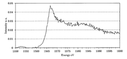
- FIG. 21 is an XAFS spectrum of the Al- and O-containing silicon material of Example 10.
- the numerical range “x to y” described in the present specification includes the lower limit x and the upper limit y within the range. Then, the upper limit value and the lower limit value, and the numerical values listed in the examples can be combined arbitrarily to constitute a numerical range. Further, numerical values arbitrarily selected from within the numerical value range can be used as upper limit and lower limit numerical values.
- the negative electrode active material of the present invention has an Al mass% (W Al %) satisfying 0 ⁇ W Al ⁇ 1 and is in the range of 1565 to 1570 eV in the X-ray absorption fine structure measurement for the k shell of Al. It is characterized in that it contains an Al- and O-containing silicon material (hereinafter sometimes referred to as the Al- and O-containing silicon material of the present invention) in which a peak showing an Al-O bond is observed.
- the Al- and O-containing silicon material of the present invention is said to be useful as a negative electrode active material for a low-resistance secondary battery because the conductivity is improved due to the presence of Al.
- a silicon material having too high an Al mass% is not preferable as a negative electrode active material.
- W Al % satisfy 0 ⁇ W Al ⁇ 0.8, and it is preferable to satisfy 0.01 ⁇ W Al ⁇ 0.8. It is more preferable to satisfy 05 ⁇ W Al ⁇ 0.6, still more preferable to satisfy 0.1 ⁇ W Al ⁇ 0.5, and in particular to satisfy 0.15 ⁇ W Al ⁇ 0.5. preferable.
- a silicon material means a material containing silicon as a main component.
- the Si mass% (W Si %) in the Al- and O-containing silicon material of the present invention preferably satisfies 60 ⁇ W Si ⁇ 90, more preferably 70 ⁇ W Si ⁇ 85, and 80 ⁇ W It is further preferable to satisfy Si ⁇ 85. If the Si mass% is too low, the capacity per unit mass of the Al- and O-containing silicon material of the present invention will be low, and the capacity as a negative electrode active material may be insufficient. If the Si mass% is too high, the degree of expansion and contraction of the Al and O-containing silicon material of the present invention during charge and discharge becomes too large, and there is a concern that the Al and O-containing silicon material of the present invention may be broken.
- Al- and O-containing silicon material of the present invention a peak showing Al—O bond is observed in the range of 1565 to 1570 eV in an X-ray absorption fine structure measurement for the k-shell of Al.
- the above-described Al-O bond is formed by the reaction between Al present on the surface of the precursor and water due to the use of water in the process of producing the precursor of the Al- and O-containing silicon material of the present invention It is considered to have been done.
- an amount of water equivalent to water reacted with Al reacts with Si to form Si-O bond. It is believed to form.
- Si having an Si—O bond it becomes difficult for Si having an Si—O bond to occlude and release charge carriers such as lithium. Therefore, in the Al-free silicon material, Si capable of storing and releasing charge carriers such as lithium at the time of charge and discharge is considered to be damaged in a relatively large amount. Therefore, in the Al- and O-containing silicon materials of the present invention, the extent to which Si that can occlude and release charge carriers such as lithium during charging and discharging is impaired due to the presence of Al, compared with the silicon materials without Al addition. Is considered to be lower.
- the negative electrode active material is a silicon material containing silicon
- the silicon of the silicon material is oxidized by oxygen contained in the SEI film to be degraded.
- the Al- and O-containing silicon material of the present invention contains Al, it is considered that the oxidative degradation of silicon is suppressed. The reason is that Al is considered to bind preferentially and stably to oxygen since it has lower electronegativity than silicon, and that Al-O bond of Al and oxygen is more stable than Si-O bond.
- oxygen having a stable Al—O bond can be said to be less likely to be involved in the oxidation of silicon which is more electronegative than Al. Therefore, a secondary battery having the Al- and O-containing silicon material of the present invention as a negative electrode active material can be expected to have a long life.
- O mass% (W 2 O %) in the Al and O-containing silicon material of the present invention satisfy 5 ⁇ W 2 O ⁇ 30, more preferably 10 ⁇ W 2 O ⁇ 25, and 12 ⁇ W 2 more preferably to satisfy O ⁇ 22, particularly preferably satisfies the 13 ⁇ W O ⁇ 21.
- the Al- and O-containing silicon material of the present invention contains a certain degree of oxygen, the life of a secondary battery including the Al- and O-containing silicon material of the present invention as a negative electrode active material is extended.
- Al and O-containing silicon material of the present invention may be present in the Al and O-containing silicon material of the present invention without departing from the spirit of the present invention.
- Other elements include those derived from raw materials and production processes. Specific examples of other elements include Fe, Ca, C and halogen.
- the Fe mass% (W Fe %) in the Al and O-containing silicon material of the present invention preferably satisfies 0 ⁇ W Fe ⁇ 3, more preferably 0 ⁇ W Fe ⁇ 1, and 0 ⁇ W. It is further preferable to satisfy Fe ⁇ 0.5, particularly preferably to satisfy 0 ⁇ W Fe ⁇ 0.3, and most preferably to satisfy 0 ⁇ W Fe ⁇ 0.1. In view of the easiness of mixing and removal of Fe , it is assumed that Fe mass% (W 2 Fe %) in the Al- and O-containing silicon material of the present invention is 0 ⁇ W 2 Fe . Moreover, it is preferable that the relationship of Al mass% (W Al %) and Fe mass% (W Fe %) satisfies W Al > W Fe, and more preferably W Al > 2 ⁇ W Fe .
- Ca mass% (W Ca %) in the Al- and O-containing silicon material of the present invention preferably satisfies 0 ⁇ W Ca ⁇ 3, more preferably 0 ⁇ W Ca ⁇ 1, and 0 ⁇ W It is further preferable to satisfy Ca ⁇ 0.5, and it is particularly preferable to satisfy 0 ⁇ W Ca ⁇ 0.3. In view of easiness of mixing and removal of Ca , it is assumed that Ca mass% (W Ca %) in the Al and O-containing silicon material of the present invention is 0 ⁇ W Ca.
- the halogen mass% (W x %) in the Al- and O-containing silicon materials of the present invention preferably satisfies 0 ⁇ W x ⁇ 3, more preferably 0 ⁇ W x ⁇ 2, and 0 ⁇ W. It is further preferable to satisfy X ⁇ 1, and it is particularly preferable to satisfy 0 ⁇ W x ⁇ 0.5. In view of easiness of mixing and removal of halogen, it is assumed that the mass% (W x %) of halogen in the Al and O-containing silicon material of the present invention is 0 ⁇ W x .
- the Al- and O-containing silicon materials of the present invention are described from the viewpoint of structure, those having a structure in which a plurality of plate-like silicon bodies are stacked in the thickness direction are preferable.
- the above plate-like silicon body is effective for efficient insertion and desorption reaction of charge carriers such as lithium ions.
- the thickness is preferably in the range of 10 nm to 100 nm, and more preferably in the range of 20 nm to 50 nm.
- the length of the plate-like silicon body in the long axis direction is preferably in the range of 0.1 ⁇ m to 50 ⁇ m.
- the plate-like silicon body preferably has a (longitudinal direction length) / (thickness) in the range of 2 to 1,000.
- the Al- and O-containing silicon material of the present invention preferably contains amorphous silicon or silicon crystallites.
- the size of the silicon crystallite is preferably nano-sized. Specifically, the silicon crystallite size is preferably in the range of 0.5 nm to 300 nm, more preferably in the range of 1 nm to 100 nm, still more preferably in the range of 1 nm to 50 nm, particularly preferably in the range of 1 nm to 10 nm preferable.
- the silicon crystallite size was determined by X-ray diffraction measurement (XRD measurement) on the Al- and O-containing silicon material of the present invention, and a Schiller using the half width of the diffraction peak of the Si (111) plane of the obtained XRD chart. It is calculated from the equation of
- the Al and O-containing silicon material of the present invention is preferably in the form of particles.
- the average particle diameter of the Al and O-containing silicon material of the present invention is preferably in the range of 1 to 30 ⁇ m, more preferably in the range of 2 to 20 ⁇ m, and still more preferably in the range of 3 to 10 ⁇ m.
- the average particle size when measured in conventional laser diffraction particle size distribution measuring apparatus, means D 50.
- One embodiment of a method for producing a negative electrode active material containing the Al and O-containing silicon material of the present invention is a) cooling the molten metal containing Ca, Al and Si to solidify it; b) reacting the solid with an aqueous acid solution to obtain a precursor of an Al- and O-containing silicon material, c) heating the precursor at 300 ° C. or higher, It is characterized by including.
- the above-described manufacturing method is suitable for manufacturing the Al and O-containing silicon material of the present invention having a structure in which a plurality of plate-like silicon bodies are stacked in the thickness direction.
- An example of the chemical change in the steps a), b) and c) of the above-mentioned production method is as follows, which is represented by an ideal reaction equation ignoring Al. a) Process: Ca + 2 Si ⁇ Ca Si 2 b) Process: 3CaSi 2 + 6HCl ⁇ Si 6 H 6 + 3CaCl 2 c) Process: Si 6 H 6 ⁇ 6 Si + 3 H 2 ⁇
- the laminated structure of the Al and O-containing silicon material of the present invention having a structure in which a plurality of plate-like silicon bodies are laminated in the thickness direction is considered to be derived from the Si layer in CaSi 2 or Si 6 H 6 .
- the process will be described.
- Ca, Al and Si used at a process a an element single-piece
- CaSi 2 may be used as part of the raw material.
- the elemental composition ratio of Ca and Si in the molten metal is preferably in the range of 1: 1.5 to 1: 2.5, more preferably in the range of 1: 1.8 to 1: 2.2, and 1: 1.
- the range of 9 to 1: 2.1 is more preferable.
- the amount of Al in the molten metal may be appropriately determined in accordance with the Al mass ratio in the Al and O-containing silicon material of the present invention to be produced. However, since Al can be dissolved in an acid, the amount of Al in the precursor may be reduced in step b) of the next step. Therefore, it is preferable to add a little more Al to the molten metal.
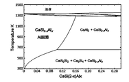
- step a Al is substituted solid solution CaSi 2-x Al x obtained by replacing the Si of CaSi 2 is manufactured. Therefore, the phase diagram of the solid solution was calculated using thermodynamic equilibrium calculation software (FactSage, Computational Mechanics Research Center, Inc.). A state diagram is shown in FIG.
- x is in the range of 0 ⁇ x ⁇ 0.16.
- the amount of Al in the composition formula of the substitutional solid solution at ordinary temperature is extremely low.
- less than 4.5% of the mass% of Al based on the total mass of Ca, Si and Al in the molten metal is preferably within the range of 0.01 to 3%, and more preferably within the range of 0.05 to 2%. Is more preferably in the range of 0.1 to 1%.
- an excessive addition of Al it is considered that CaAl 2 Si 2 also generates, CaAl 2 Si 2 disappears by decomposition in the next step of b) step.
- the molten metal temperature in the step a) may be a temperature at which a mixture of Ca, Al and Si can be a molten metal.
- the molten metal means a liquid-like state of a mixture of Ca, Al and Si.
- the temperature of the molten metal is preferably in the range of 1050 ° C. to 1800 ° C., more preferably in the range of 1100 ° C. to 1500 ° C., and still more preferably in the range of 1200 ° C. to 1400 ° C.
- a heating device used at a) process a high frequency induction heating device, an electric furnace, and a gas furnace can be used, for example.
- the step a) may be performed under pressure or reduced pressure conditions, or under an inert gas atmosphere such as argon, helium or nitrogen.
- the melt it is preferable to cool the melt at a rate as fast as possible.
- the formation of the interstitial solid solution can also be expected.
- the molten metal may be poured into a predetermined mold and left at room temperature, but a cooling method using a rapid cooling device may be used.
- the rapid cooling device described in the present specification does not include a device for leaving and cooling the molten metal, but means a device for forcibly cooling the molten metal.
- a cooling means such as melt span method, strip casting method, or melt spinning method
- a cooling method such as an atomizing method for spraying a fluid onto a molten metal
- the cooling device using the means can be illustrated.
- a gas atomizing method, a water atomizing method, a centrifugal atomizing method, and a plasma atomizing method can be exemplified.
- Specific rapid cooling devices include liquid rapid solidification devices, rapid cooling thin plate production devices, in-liquid spinning devices, gas atomizing devices, water atomizing devices, rotating disk devices, rotating electrode method devices (Nisshin Giken Co., Ltd.), liquid A quenching apparatus and a gas atomizing apparatus (above, Makabe Giken Co., Ltd.) can be exemplified.
- As a preferable cooling rate 1000 to 100,000 ° C./second can be exemplified.
- an annealing step may be added in which heating is performed while maintaining the solid state obtained by cooling. From the phase diagram of FIG. 1, it is considered that the substitutional solid solution CaSi 2 -xAl x is most likely to be formed at around 900 ° C. Therefore, the heating temperature in the annealing step is preferably 800 to 1000 ° C., and more preferably 850 to 950 ° C. The heating time may be, for example, 1 to 50 hours or 5 to 30 hours. Naturally, the solid is cooled after the annealing step.
- the solid obtained by cooling may be crushed or further classified.
- Step b) is a step of reacting the solid obtained in step a) with an aqueous acid solution to obtain a precursor of an Al- and O-containing silicon material.
- Precursor of Al and O-containing silicon material because the basic skeleton of Si layer by CaSi 2-x Al x or CaSi 2 is maintained, forms a lamellar.
- hydrofluoric acid hydrochloric acid, hydrobromic acid, hydroiodic acid, sulfuric acid, nitric acid, phosphoric acid, formic acid, acetic acid, methanesulfonic acid, tetrafluoroboric acid, hexafluorophosphoric acid, hexafluoro acid Arsenic acid, fluoroantimonic acid, hexafluorosilicic acid, hexafluorogermanic acid, hexafluorotin (IV) acid, trifluoroacetic acid, hexafluorotitanic acid, hexafluorozirconic acid, trifluoromethanesulfonic acid, fluorosulfonic acid are exemplified. Ru. These acids may be used alone or in combination.
- step b it is preferable to use the acid in molar ratio in excess of Ca contained in the solid obtained in the step a).
- the step b) is carried out using an aqueous acid solution.
- the reason why water is used as the solvent is that it is easy to separate the target substance and to remove by-products such as CaCl 2 and the like.
- the reaction conditions in the same step are preferably reduced pressure conditions such as vacuum or under an inert gas atmosphere, and it is preferable to set temperature conditions below room temperature such as an ice bath. The reaction time of the same process may be set appropriately.
- the step b) is carried out using an aqueous acid solution, and the Al—H bond or Si—H bond formed in the reaction formula described in the preceding paragraph can react with water. Therefore, in the step b), for example, the following reaction is considered to proceed. Si 6-3x Al 3x H 6 + 3H 2 O ⁇ Si 6-3x Al 3x H 3 (OH) 3 + 3H 2 ⁇ Therefore, the precursor of the Al- and O-containing silicon material contains oxygen. Moreover, the element derived from the anion of the used acid may also be included.
- the step c) is a step of heating the precursor of the Al- and O-containing silicon material at 300 ° C. or higher to release hydrogen, water and the like to obtain an Al- and O-containing silicon material.
- the step c) is preferably carried out in a non-oxidizing atmosphere having a lower oxygen content than under normal atmosphere.
- a non-oxidizing atmosphere a reduced pressure atmosphere including vacuum and an inert gas atmosphere can be exemplified.
- the heating temperature is preferably in the range of 350 ° C. to 950 ° C., and more preferably in the range of 400 ° C. to 900 ° C. If the heating temperature is too low, hydrogen may not be sufficiently released, and if the heating temperature is too high, energy is wasted.
- the heating time may be set appropriately according to the heating temperature. It is preferable to determine the heating time while measuring the amount of hydrogen and the like that escapes from the reaction system.
- the heating temperature and the heating time By appropriately selecting the heating temperature and the heating time, the ratio of amorphous silicon and silicon crystallite contained in the produced Al and O-containing silicon material and the size of silicon crystallite can also be adjusted. By appropriately selecting the heating temperature and the heating time, it is also possible to prepare the shape of a nano-level thick layer including amorphous silicon and silicon crystallite contained in the produced Al and O-containing silicon material.
- the obtained Al and O-containing silicon material may be crushed or further classified.
- the Al- and O-containing silicon material of the present invention can be used as a negative electrode active material of a storage battery such as a secondary battery such as a lithium ion secondary battery, an electric double layer capacitor and a lithium ion capacitor. Further, the Al- and O-containing silicon material of the present invention can also be used as, for example, a material such as a CMOS, a semiconductor memory, a solar cell, or a photocatalytic material.
- the lithium ion secondary battery of the present invention including the Al- and O-containing silicon material of the present invention as a negative electrode active material will be described as a representative example of the power storage device.
- the lithium ion secondary battery of the present invention comprises a positive electrode, a negative electrode comprising the Al- and O-containing silicon material of the present invention as a negative electrode active material, an electrolytic solution and a separator.
- the positive electrode has a current collector and a positive electrode active material layer bonded to the surface of the current collector.
- the current collector refers to a chemically inert electron conductor for keeping current flowing to the electrode during discharge or charge of the lithium ion secondary battery.
- As the current collector at least one selected from silver, copper, gold, aluminum, tungsten, cobalt, zinc, nickel, iron, platinum, tin, indium, titanium, ruthenium, tantalum, chromium, molybdenum, stainless steel, etc. A metal material can be illustrated.
- the current collector may be coated with a known protective layer. What processed the surface of a collector by a well-known method may be used as a collector.
- the current collector can take the form of a foil, a sheet, a film, a line, a rod, a mesh or the like. Therefore, as the current collector, for example, metal foils such as copper foil, nickel foil, aluminum foil, and stainless steel foil can be suitably used.
- the thickness is preferably in the range of 1 ⁇ m to 100 ⁇ m.
- the positive electrode active material layer contains a positive electrode active material and, if necessary, a conductive aid and / or a binder.
- a positive electrode active material spinel such as LiMn 2 O 4 and a solid solution composed of a mixture of spinel and layered compound, LiMPO 4 , LiMVO 4 or Li 2 MSiO 4 (M in the formula is Co, Ni, Mn, Polyanionic compounds represented by (at least one of Fe) and the like can be mentioned.
- tavorite compound (the M a transition metal) LiMPO 4 F, such as LiFePO 4 F represented by, Limbo 3 such LiFeBO 3 (M is a transition metal) include borate-based compound represented by be able to.
- any metal oxide used as a positive electrode active material may have the above composition formula as a basic composition, and one obtained by substituting a metal element contained in the basic composition with another metal element can also be used as a positive electrode active material .
- a positive electrode active material a positive electrode active material containing no lithium ion contributing to charge and discharge, for example, a simple substance of sulfur, a compound of sulfur and carbon, a metal sulfide such as TiS 2 , V 2 O 5 , MnO Oxides such as 2 , polyaniline and anthraquinone, and compounds containing these aromatics in the chemical structure, conjugated materials such as conjugated diacetic acid organic substances, and other known materials can also be used.
- a compound having a stable radical such as nitroxide, nitronyl nitroxide, galvinoxyl, phenoxyl or the like may be adopted as the positive electrode active material.
- a positive electrode active material containing no lithium it is necessary to add ions to the positive electrode and / or the negative electrode by a known method.
- a metal or a compound containing the ions may be used.
- a conductive aid is added to enhance the conductivity of the electrode. Therefore, the conductive additive may be optionally added when the conductivity of the electrode is insufficient, and may not be added when the conductivity of the electrode is sufficiently excellent.
- the conductive auxiliary agent may be any chemically active high electron conductor, and carbon black particles such as carbon black, graphite, acetylene black, ketjen black (registered trademark), vapor grown carbon fiber (vapor grown carbon) Fiber), and various metal particles are exemplified. These conductive assistants can be added to the active material layer singly or in combination of two or more.
- the binder plays the role of anchoring the active material and the conductive aid to the surface of the current collector and maintaining the conductive network in the electrode.
- the binder may, for example, be a fluorine-containing resin such as polyvinylidene fluoride, polytetrafluoroethylene or fluororubber, a thermoplastic resin such as polypropylene or polyethylene, an imide resin such as polyimide or polyamideimide, an alkoxysilyl group-containing resin, Examples of acrylic resins such as acrylic acid, styrene-butadiene rubber (SBR), alginates such as carboxymethylcellulose, sodium alginate and ammonium alginate, water-soluble cellulose ester cross-linked product, starch-acrylic acid graft polymer it can. These binders may be used alone or in combination.
- a crosslinked polymer in which a carboxyl group-containing polymer such as polyacrylic acid or polymethacrylic acid as disclosed in WO 2016/063882 is crosslinked with a polyamine such as diamine may be used as a binder.
- diamine used for the cross-linked polymer examples include alkylene diamines such as ethylene diamine, propylene diamine and hexamethylene diamine, 1,4-diaminocyclohexane, 1,3-diaminocyclohexane, isophorone diamine, bis (4-aminocyclohexyl) methane and the like.
- Saturated carbocyclic ring diamine m-phenylenediamine, p-phenylenediamine, 4,4'-diaminodiphenylmethane, 4,4'-diaminodiphenylether, bis (4-aminophenyl) sulfone, benzidine, o-tolidine, 2,4- Aromatic diamines such as tolylene diamine, 2,6-tolylene diamine, xylylene diamine and naphthalene diamine can be mentioned.
- the blending ratio of the binder in the active material layer is, in mass ratio, preferably active material: binder 1: 0.001 to 1: 0.3, 1: 0.005 to 1: 0 It is more preferably 0.2, and more preferably 1: 0.01 to 1: 0.15.
- the negative electrode includes a current collector and a negative electrode active material layer bonded to the surface of the current collector.
- As the current collector one described for the positive electrode may be appropriately adopted appropriately.
- the negative electrode active material layer contains a negative electrode active material and, if necessary, a conductive aid and / or a binder.
- the negative electrode active material only the Al and O-containing silicon material of the present invention may be adopted, or the Al and O-containing silicon material of the present invention may be used in combination with a known negative electrode active material. What coated Al and O containing silicon material of this invention with carbon may be used as a negative electrode active material.
- C mass% (W C %) preferably satisfies 0 ⁇ W C ⁇ 30, 1 ⁇ more preferably satisfies W C ⁇ 20, more preferably to satisfy 2 ⁇ W C ⁇ 15, particularly preferably satisfies the 5 ⁇ W C ⁇ 10.
- those described for the positive electrode may be appropriately adopted at the same mixing ratio.
- an active material layer on the surface of a current collector current collection can be performed using conventionally known methods such as roll coating, die coating, dip coating, doctor blade method, spray coating, and curtain coating.
- the active material may be applied to the surface of the body.
- the active material, the solvent, and, if necessary, the binder and / or the conductive auxiliary agent are mixed to prepare a slurry.
- the solvent include N-methyl-2-pyrrolidone, methanol, methyl isobutyl ketone and water.
- the slurry is applied to the surface of a current collector and then dried. The dried one may be compressed to increase the electrode density.
- the electrolytic solution contains a non-aqueous solvent and an electrolyte dissolved in the non-aqueous solvent.
- cyclic esters As the non-aqueous solvent, cyclic esters, linear esters, ethers and the like can be used.
- examples of cyclic esters include ethylene carbonate, propylene carbonate, butylene carbonate, fluoroethylene carbonate, gamma-butyrolactone, vinylene carbonate, 2-methyl-gamma-butyrolactone, acetyl-gamma-butyrolactone and gamma-valerolactone.
- chain ester examples include dimethyl carbonate, diethyl carbonate, dibutyl carbonate, dipropyl carbonate, ethyl methyl carbonate, alkyl propionic acid ester, malonic acid dialkyl ester, acetic acid alkyl ester and the like.
- ethers tetrahydrofuran, 2-methyltetrahydrofuran, 1,4-dioxane, 1,2-dimethoxyethane, 1,2-diethoxyethane, 1,2-dibutoxyethane can be exemplified.
- non-aqueous solvent a compound in which part or all of hydrogens in the chemical structure of the above specific solvent is substituted with fluorine may be adopted.
- Examples of the electrolyte include lithium salts such as LiClO 4 , LiAsF 6 , LiPF 6 , LiBF 4 , LiCF 3 SO 3 , and LiN (CF 3 SO 2 ) 2 .
- lithium salts such as LiClO 4 , LiPF 6 , LiBF 4 , LiCF 3 SO 3 and the like in a nonaqueous solvent such as fluoroethylene carbonate, ethyl methyl carbonate, ethylene carbonate, dimethyl carbonate, propylene carbonate, diethyl carbonate
- a nonaqueous solvent such as fluoroethylene carbonate, ethyl methyl carbonate, ethylene carbonate, dimethyl carbonate, propylene carbonate, diethyl carbonate
- the separator separates the positive electrode and the negative electrode, and allows lithium ions to pass while preventing a short circuit due to the contact of the both electrodes.
- synthetic resins such as polytetrafluoroethylene, polypropylene, polyethylene, polyimide, polyamide, polyaramid (Aromatic polyamide), polyester, polyacrylonitrile, etc., polysaccharides such as cellulose and amylose, natural substances such as fibroin, keratin, lignin and suberin Examples thereof include porous bodies, non-woven fabrics, and woven fabrics using one or more kinds of electrically insulating materials such as polymers and ceramics.
- the separator may have a multilayer structure.
- a separator is sandwiched between the positive electrode and the negative electrode as necessary to form an electrode body.
- the electrode body may be any of a laminated type in which the positive electrode, the separator and the negative electrode are stacked, or a wound type in which the positive electrode, the separator and the negative electrode are wound.
- the shape of the lithium ion secondary battery of the present invention is not particularly limited, and various shapes such as cylindrical, square, coin, and laminate types can be adopted.
- the lithium ion secondary battery of the present invention may be mounted on a vehicle.
- the vehicle may be a vehicle using electric energy from a lithium ion secondary battery for all or part of its power source, and may be, for example, an electric vehicle, a hybrid vehicle, or the like.
- a lithium ion secondary battery is mounted on a vehicle, a plurality of lithium ion secondary batteries may be connected in series to form a battery pack.
- various household appliances driven by a battery such as a personal computer and a mobile communication apparatus, as well as a vehicle, an office apparatus, an industrial apparatus and the like can be mentioned.
- the lithium ion secondary battery of the present invention can be used in wind power generation, solar power generation, hydroelectric power generation, storage devices and power smoothing devices for electric power systems, power sources for power and / or accessories of ships, etc., aircraft, Power supply source for power of spacecraft and / or accessories, auxiliary power supply for vehicles not using electricity as power source, power supply for mobile home robots, power supply for system backup, power supply for uninterruptible power supply, You may use for the electrical storage apparatus which stores temporarily the electric power required for charge in the charge station etc. for electric vehicles.
- Example 1 The Al- and O-containing silicon material and lithium ion secondary battery of Example 1 were manufactured as follows.
- Step Ca, Al and Si were weighed in a carbon crucible.
- the elemental composition ratio of Ca and Si was 1: 2, and the amount of Al added was 1% with respect to the total mass of Ca, Al and Si.
- a carbon crucible was heated at around 1300 ° C. in a high frequency induction heating apparatus under an argon gas atmosphere to obtain a molten metal containing Ca, Al and Si.
- the molten metal is poured into a predetermined mold to cool and solidify.
- the solid was pulverized into a powder and then subjected to the step b).
- Example 1 The negative electrode of Example 1 and the lithium ion secondary battery of Example 1 were manufactured as follows using the Al- and O-containing silicon material of Example 1.
- a polyacrylic acid having a weight average molecular weight of 800,000 was dissolved in N-methyl-2-pyrrolidone to prepare a polyacrylic acid solution containing 10% by mass of polyacrylic acid.
- a solution of 4,4'-diaminodiphenylmethane was prepared by dissolving 0.2 g (1.0 mmol) of 4,4'-diaminodiphenylmethane in 0.4 mL of N-methyl-2-pyrrolidone.
- the slurry was prepared by mixing the solution and an appropriate amount of N-methyl-2-pyrrolidone.
- a copper foil was prepared as a current collector for the negative electrode.
- the slurry was applied in the form of a film on the surface of the copper foil using a doctor blade.
- the copper foil coated with the slurry was dried at 80 ° C. for 15 minutes to remove N-methyl-2-pyrrolidone. Thereafter, the resultant was pressed and heated at 180 ° C. for 30 minutes in a reduced pressure atmosphere using a vacuum pump to manufacture the negative electrode of Example 1 in which the negative electrode active material layer was formed.
- a polyethylene porous membrane was prepared as a separator.
- a solution in which LiPF 6 was dissolved at a concentration of 2 mol / L in a mixed solvent in which fluoroethylene carbonate and ethyl methyl carbonate were mixed at a volume ratio of 19: 81 was used as an electrolytic solution.
- Comparative example 1 In the step a), the silicon material of Comparative Example 1, the negative electrode of Comparative Example 1, and the lithium ion secondary battery of Comparative Example 1 were produced in the same manner as in Example 1 except that Al was not added.
- Elemental analysis of the Al- and O-containing silicon material of Example 1 and the silicon material of Comparative Example 1 was performed using inductively coupled plasma atomic emission spectrometry (ICP-AES).
- ICP-AES inductively coupled plasma atomic emission spectrometry
- Al mass% is 0.25%
- Fe mass% is 0%
- Al mass% in the silicon material of Comparative Example 1 is 0%
- Fe mass % was 0%.
- the lithium ion secondary battery of Example 1 was adjusted to an SOC (State of Charge) of 15% in a thermostat of 25 ° C. Then, the lithium ion secondary battery was discharged for 10 seconds at a constant current of 1 C rate. The resistance was calculated by dividing the amount of change in voltage before and after discharge by the current value. The same test was performed on the lithium ion secondary battery of Comparative Example 1. The resistance of the lithium ion secondary battery of Example 1 was 3.3 ⁇ , and the resistance of the lithium ion secondary battery of Comparative Example 1 was 3.6 ⁇ . It was supported that the resistance of the lithium ion secondary battery is lowered by using the Al and O containing silicon material.
- Example 2 The Al- and O-containing silicon material, the negative electrode, and the lithium ion secondary battery of Example 2 were produced as follows.
- Step Ca Al and Si were weighed in a carbon crucible.
- the elemental composition ratio of Ca and Si was 1: 2, and the amount of Al added was 1% with respect to the total mass of Ca, Al and Si.
- a carbon crucible was heated at around 1300 ° C. in a high frequency induction heating apparatus under an argon gas atmosphere to obtain a molten metal containing Ca, Al and Si.
- the molten metal is poured into a predetermined mold and cooled to form a solid.
- the solid was pulverized into a powder and then subjected to the step b).
- Step 2 The Al and O-containing silicon material precursor was heated at 900 ° C. for 1 hour in a nitrogen gas atmosphere to produce the Al- and O-containing silicon material of Example 2.
- Example 2 The negative electrode of Example 2 and the lithium ion secondary battery of Example 2 were manufactured as follows using the Al- and O-containing silicon materials of Example 2.
- a polyacrylic acid having a weight average molecular weight of 800,000 was dissolved in N-methyl-2-pyrrolidone to prepare a polyacrylic acid solution containing 10% by mass of polyacrylic acid.
- a solution of 4,4'-diaminodiphenylmethane was prepared by dissolving 0.2 g (1.0 mmol) of 4,4'-diaminodiphenylmethane in 0.4 mL of N-methyl-2-pyrrolidone.
- the slurry was prepared by mixing the solution and an appropriate amount of N-methyl-2-pyrrolidone.
- a copper foil was prepared as a current collector for the negative electrode.
- the slurry was applied in the form of a film on the surface of the copper foil using a doctor blade.
- the copper foil coated with the slurry was dried at 80 ° C. for 15 minutes to remove N-methyl-2-pyrrolidone. After that, pressing was performed and heating was performed at 180 ° C. for 30 minutes in a reduced pressure atmosphere using a vacuum pump to manufacture the negative electrode of Example 2 in which the negative electrode active material layer was formed.
- the negative electrode of Example 2 was cut to a diameter of 11 mm to obtain an evaluation electrode.
- a metal lithium foil having a thickness of 500 ⁇ m was cut to a diameter of 13 mm and used as a counter electrode.
- a glass filter (Hoechst Celanese) and celgard 2400 (Polypore Co., Ltd.) which is a single-layer polypropylene were prepared as a separator.
- the volume ratio of ethylene carbonate and diethyl carbonate 1: LiPF 6 was prepared the electrolytic solution at a concentration 1 mol / L in a mixed solvent obtained by mixing 1.
- the two types of separators were sandwiched between the counter electrode and the evaluation electrode in the order of the counter electrode, the glass filter, celgard 2400, and the evaluation electrode to form an electrode body.
- the electrode body was housed in a coin-type battery case CR2032 (Housen Co., Ltd.), and an electrolyte was further injected to obtain a coin-type battery.
- the resultant was used as a lithium ion secondary battery of Example 2.
- Example 3 The carbon-coated Al- and O-containing silicon material is used as the Al- and O-containing silicon material of Example 3 by adding the following carbon-coating step after the step c) of increasing the production scale, and this is used as the negative electrode active.
- the Al and O-containing silicon material, the negative electrode, and the lithium ion secondary battery of Example 3 were manufactured in the same manner as in Example 2 except that they were used as substances.
- Step c) The Al and O-containing silicon material obtained in step c) is placed in a rotary kiln type reactor, and thermal CVD is performed at 880 ° C. and a residence time of 60 minutes under aeration of propane and argon mixed gas. A coated Al and O containing silicon material was obtained.
- Example 4 Powdered CaSi 2 containing Al and Fe as impurities was prepared.
- elemental analysis of the CaSi 2 was performed using ICP-AES, it was 38 mass% of Ca, 57 mass% of Si, 4 mass% of Fe, and 1 mass% of Al.
- the Al and O-containing silicon material, the negative electrode, and the lithium ion secondary battery of Example 4 were manufactured in the same manner as in Example 3 except that step b) and the following steps were performed using the CaSi 2 .
- Comparative example 2 The silicon material, the negative electrode, and the lithium ion secondary battery of Comparative Example 2 were manufactured in the same manner as in Example 2 except that Al was not added in the step a).
- Comparative example 3 (Comparative example 3)
- the silicon material, the negative electrode, and the lithium ion secondary battery of Comparative Example 3 were manufactured in the same manner as in Example 2 except that Al was not added and Fe was added.
- Fe in the step a) was added in an amount of 4% with respect to the total mass of Ca, Fe and Si.
- Elemental analysis was performed on the Al- and O-containing silicon materials of Examples 2 to 4 and the silicon materials of Comparative Examples 2 and 3 using a fluorescent X-ray analyzer (XRF).
- XRF fluorescent X-ray analyzer
- elemental analysis of oxygen on the Al- and O-containing silicon materials of Examples 2 to 4 and the silicon materials of Comparative Examples 2 and 3 Did.
- elemental analysis for carbon was performed on the carbon-coated Al and O-containing silicon materials of Example 3 and Example 4 using a carbon / sulfur analyzer.
- Example 2 The results of these elemental analyzes are shown in Table 1 as mass%.
- the presence of a slight amount of Fe in Example 2, Example 3, and Comparative Example 2 is because Fe is contained as an impurity in the metal of the raw material.
- O, Ca and Cl contained in all silicon materials are derived from the solvent (water) used in the production, the raw material, the anion of the acid and the like.
- Initial efficiency (%) 100 ⁇ (initial charge capacity) / (initial discharge capacity)
- Capacity retention rate (%) 100 ⁇ (charge capacity at each cycle) / (charge capacity at first cycle)
- Example 5 The Al- and O-containing silicon material, the negative electrode, and the lithium ion secondary battery of Example 5 were produced as follows.
- Step Ca Al and Si were weighed in a carbon crucible.
- the elemental composition ratio of Ca and Si was 1: 2, and the amount of Al added was 0.1% with respect to the total mass of Ca, Al and Si.
- a carbon crucible was heated at around 1300 ° C. in a high frequency induction heating apparatus under an argon gas atmosphere to obtain a molten metal containing Ca, Al and Si.
- the molten metal is poured into a predetermined mold and cooled to form a solid.
- the solid was pulverized into a powder and then subjected to the step b).
- the negative electrode of Example 5 and the lithium ion secondary battery of Example 5 were manufactured using the Al- and O-containing silicon materials of Example 5 as follows.
- a polyacrylic acid having a weight average molecular weight of 800,000 was dissolved in N-methyl-2-pyrrolidone to prepare a polyacrylic acid solution containing 10% by mass of polyacrylic acid.
- a solution of 4,4'-diaminodiphenylmethane was prepared by dissolving 0.2 g (1.0 mmol) of 4,4'-diaminodiphenylmethane in 0.4 mL of N-methyl-2-pyrrolidone.
- the slurry was prepared by mixing the solution and an appropriate amount of N-methyl-2-pyrrolidone.
- a copper foil was prepared as a current collector for the negative electrode.
- the slurry was applied in the form of a film on the surface of the copper foil using a doctor blade.
- the copper foil coated with the slurry was dried at 80 ° C. for 15 minutes to remove N-methyl-2-pyrrolidone. After that, pressing was performed and heating was performed at 180 ° C. for 30 minutes in a reduced pressure atmosphere using a vacuum pump to manufacture the negative electrode of Example 5 in which the negative electrode active material layer was formed.
- the negative electrode of Example 5 was cut to a diameter of 11 mm to obtain an evaluation electrode.
- a metal lithium foil having a thickness of 500 ⁇ m was cut to a diameter of 13 mm and used as a counter electrode.
- a glass filter (Hoechst Celanese) and celgard 2400 (Polypore Co., Ltd.) which is a single-layer polypropylene were prepared as a separator.
- the volume ratio of ethylene carbonate and diethyl carbonate 1: LiPF 6 was prepared the electrolytic solution at a concentration 1 mol / L in a mixed solvent obtained by mixing 1.
- the two types of separators were sandwiched between the counter electrode and the evaluation electrode in the order of the counter electrode, the glass filter, celgard 2400, and the evaluation electrode to form an electrode body.
- the electrode body was housed in a coin-type battery case CR2032 (Housen Co., Ltd.), and an electrolyte was further injected to obtain a coin-type battery.
- the resultant was used as a lithium ion secondary battery of Example 5.
- Example 6 Al and O-containing silicon material of Example 6 in the same manner as Example 5 except that in the step a), the addition amount of Al is 0.3% with respect to the total mass of Ca, Al and Si , A negative electrode and a lithium ion secondary battery were manufactured.
- Example 7 Al and O-containing silicon material of Example 7 in the same manner as Example 5, except that in the step a), the addition amount of Al is 0.5% with respect to the total mass of Ca, Al and Si , A negative electrode and a lithium ion secondary battery were manufactured.
- Example 8 Al and O-containing silicon material of Example 8, negative electrode in the same manner as Example 5, except that in the step a), the amount of Al added is 1% with respect to the total mass of Ca, Al and Si And a lithium ion secondary battery.
- Example 9 The Al and O-containing silicon material, negative electrode and lithium ion secondary battery of Example 9 were produced in the same manner as in Example 8 except that the following annealing step was added to the step a).
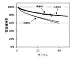
- Example 7 The lithium ion secondary batteries of Example 5 to Example 9 were discharged to 0.01 V at a current of 0.2 mA and then charged to 1.0 V at a current of 0.2 mA. went. Furthermore, for the lithium ion secondary batteries of Example 5 to Example 9 after the initial charge and discharge, discharging to 0.01 V with a current of 0.5 mA and then charging to 1.0 V with a current of 0.5 mA The charge and discharge cycle of 50 cycles was performed. In addition, the lithium ion secondary batteries of Examples 5 to 9 were discharged to 0.01 V at a current of 0.2 mA, and then charged to 0.8 V at a current of 0.2 mA. Discharge was done.
- Initial efficiency (%) 100 ⁇ (initial charge capacity) / (initial discharge capacity)
- Capacity retention rate (%) 100 ⁇ (charge capacity at 50 cycles) / (charge capacity at first cycle)
- the results of the initial discharge capacity, the initial charge capacity (1.0 V and 0.8 V), the initial efficiency (1.0 V and 0.8 V), and the capacity retention rate are shown in Tables 4 and 5 together with the results of Al mass%.
- Step Ca, Al and Si were weighed in a carbon crucible.
- the elemental composition ratio of Ca and Si was 1: 2, and the amount of Al added was 1% with respect to the total mass of Ca, Al and Si.
- a carbon crucible was heated at around 1300 ° C. in a high frequency induction heating apparatus under an argon gas atmosphere to obtain a molten metal containing Ca, Al and Si.
- the molten metal is poured into a predetermined mold to cool and solidify.
- the solid was pulverized into a powder and then subjected to the step b).
- Step c) The Al and O-containing silicon material obtained in step c) is placed in a rotary kiln type reactor, and thermal CVD is performed at 880 ° C. and a residence time of 60 minutes under aeration of propane and argon mixed gas. A coated Al and O containing silicon material was obtained. The carbon coated Al and O containing silicon material was taken as the Al and O containing silicon material of Example 10.
Landscapes
- Chemical & Material Sciences (AREA)
- Chemical Kinetics & Catalysis (AREA)
- Electrochemistry (AREA)
- General Chemical & Material Sciences (AREA)
- Organic Chemistry (AREA)
- Inorganic Chemistry (AREA)
- Engineering & Computer Science (AREA)
- Composite Materials (AREA)
- Materials Engineering (AREA)
- Manufacturing & Machinery (AREA)
- Battery Electrode And Active Subsutance (AREA)
- Silicon Compounds (AREA)
Priority Applications (2)
| Application Number | Priority Date | Filing Date | Title |
|---|---|---|---|
| CN201880059429.4A CN111095628B (zh) | 2017-09-14 | 2018-06-18 | 含有含Al和O的硅材料的负极活性物质 |
| US16/645,657 US11688852B2 (en) | 2017-09-14 | 2018-06-18 | Negative electrode active material including Al- and O-containing silicon material |
Applications Claiming Priority (2)
| Application Number | Priority Date | Filing Date | Title |
|---|---|---|---|
| JP2017-177198 | 2017-09-14 | ||
| JP2017177198A JP6926873B2 (ja) | 2017-09-14 | 2017-09-14 | Al及びO含有シリコン材料 |
Publications (1)
| Publication Number | Publication Date |
|---|---|
| WO2019053982A1 true WO2019053982A1 (ja) | 2019-03-21 |
Family
ID=65722643
Family Applications (1)
| Application Number | Title | Priority Date | Filing Date |
|---|---|---|---|
| PCT/JP2018/023075 Ceased WO2019053982A1 (ja) | 2017-09-14 | 2018-06-18 | Al及びO含有シリコン材料を含む負極活物質 |
Country Status (4)
| Country | Link |
|---|---|
| US (1) | US11688852B2 (cg-RX-API-DMAC7.html) |
| JP (1) | JP6926873B2 (cg-RX-API-DMAC7.html) |
| CN (1) | CN111095628B (cg-RX-API-DMAC7.html) |
| WO (1) | WO2019053982A1 (cg-RX-API-DMAC7.html) |
Cited By (1)
| Publication number | Priority date | Publication date | Assignee | Title |
|---|---|---|---|---|
| EP4297117A1 (en) * | 2022-06-23 | 2023-12-27 | SK On Co., Ltd. | Negative electrode for lithium secondary battery and method of manufacturing the same |
Families Citing this family (2)
| Publication number | Priority date | Publication date | Assignee | Title |
|---|---|---|---|---|
| US11769872B2 (en) * | 2021-03-17 | 2023-09-26 | GM Global Technology Operations LLC | Pre-lithiated silicon particles and methods of forming the same |
| CN116868373B (zh) * | 2023-02-28 | 2024-08-09 | 宁德时代新能源科技股份有限公司 | 硅基负极活性材料、二次电池及用电装置 |
Citations (4)
| Publication number | Priority date | Publication date | Assignee | Title |
|---|---|---|---|---|
| JP2006100255A (ja) * | 2004-09-03 | 2006-04-13 | Shin Etsu Chem Co Ltd | 非水電解質二次電池負極材用金属珪素粉末及び非水電解質二次電池用負極材 |
| JP2016124783A (ja) * | 2014-12-26 | 2016-07-11 | 株式会社半導体エネルギー研究所 | 珪素酸化物及び蓄電池 |
| JP2017027959A (ja) * | 2009-12-24 | 2017-02-02 | ソニー株式会社 | リチウムイオン二次電池、リチウムイオン二次電池用負極、リチウムイオン二次電池用負極活物質、電動工具、電気自動車および電力貯蔵システム |
| JP2017091978A (ja) * | 2015-11-17 | 2017-05-25 | 信越化学工業株式会社 | 負極活物質、混合負極活物質材料、非水電解質二次電池用負極、リチウムイオン二次電池、及び負極活物質の製造方法 |
Family Cites Families (17)
| Publication number | Priority date | Publication date | Assignee | Title |
|---|---|---|---|---|
| CN101453016A (zh) * | 2007-11-29 | 2009-06-10 | 比亚迪股份有限公司 | 负极活性材料及其制备方法和负极及锂离子电池 |
| JP5471284B2 (ja) | 2009-10-20 | 2014-04-16 | 株式会社豊田中央研究所 | リチウム二次電池用電極及びそれを備えたリチウム二次電池 |
| JP5666378B2 (ja) * | 2010-05-24 | 2015-02-12 | 信越化学工業株式会社 | 非水電解質二次電池用負極活物質の製造方法及び非水電解質二次電池用負極活物質並びに非水電解質二次電池用負極材、非水電解質二次電池用負極、非水電解質二次電池 |
| JP6010429B2 (ja) | 2012-11-08 | 2016-10-19 | 信越化学工業株式会社 | 非水電解質二次電池用負極活物質用の珪素含有粒子の製造方法、非水電解質二次電池用負極材の製造方法、及び非水電解質二次電池の製造方法 |
| DE112013005568T5 (de) | 2012-11-21 | 2015-09-17 | Kabushiki Kaisha Toyota Jidoshokki | Nanokristallines Siliciummaterial, Aktivmaterial für eine negative Elektrode, Herstellungsverfahren für das Material und elektrisches Speichergerät |
| DE112013006722B4 (de) * | 2013-02-22 | 2020-10-15 | Kabushiki Kaisha Toyota Jidoshokki | Negativelektrodenaktivmaterial, Herstellungsverfahren für selbiges und elektrischer Speicherapparat |
| JP6068237B2 (ja) | 2013-04-02 | 2017-01-25 | 本田技研工業株式会社 | 電解質−負極構造体及びそれを備えるリチウムイオン二次電池 |
| US20150044560A1 (en) | 2013-08-09 | 2015-02-12 | Semiconductor Energy Laboratory Co., Ltd. | Electrode for lithium-ion secondary battery and manufacturing method thereof, and lithium-ion secondary battery |
| WO2015097974A1 (ja) * | 2013-12-25 | 2015-07-02 | 株式会社豊田自動織機 | 負極活物質とその製造方法及び蓄電装置 |
| KR102143708B1 (ko) * | 2014-01-31 | 2020-08-11 | 가부시키가이샤 도요다 지도숏키 | 비수계 이차 전지용 부극 및 비수계 이차 전지, 부극 활물질 및 그 제조 방법, 나노 실리콘과 탄소층과 카티온성 폴리머층을 구비하는 복합체, 나노 실리콘과 탄소층으로 이루어지는 복합체의 제조 방법 |
| JP6302307B2 (ja) | 2014-03-19 | 2018-03-28 | 積水化学工業株式会社 | シート積層型リチウムイオン二次電池 |
| JP6126546B2 (ja) | 2014-03-26 | 2017-05-10 | 株式会社日立製作所 | リチウムイオン二次電池用負極の製造方法及び製造装置 |
| JP6318859B2 (ja) * | 2014-05-29 | 2018-05-09 | 株式会社豊田自動織機 | 銅含有シリコン材料及びその製造方法と負極活物質及び二次電池 |
| EP3150555A4 (en) * | 2014-05-29 | 2018-02-21 | Kabushiki Kaisha Toyota Jidoshokki | Silicon material and secondary cell negative electrode |
| WO2016031099A1 (ja) * | 2014-08-27 | 2016-03-03 | 株式会社豊田自動織機 | 炭素被覆シリコン材料の製造方法 |
| WO2016031146A1 (ja) * | 2014-08-27 | 2016-03-03 | 株式会社豊田自動織機 | 炭素被覆シリコン材料の製造方法 |
| JP6548959B2 (ja) * | 2015-06-02 | 2019-07-24 | 信越化学工業株式会社 | 非水電解質二次電池用負極活物質、非水電解質二次電池用負極、及び非水電解質二次電池、並びに負極活物質粒子の製造方法 |
-
2017
- 2017-09-14 JP JP2017177198A patent/JP6926873B2/ja active Active
-
2018
- 2018-06-18 US US16/645,657 patent/US11688852B2/en active Active
- 2018-06-18 WO PCT/JP2018/023075 patent/WO2019053982A1/ja not_active Ceased
- 2018-06-18 CN CN201880059429.4A patent/CN111095628B/zh active Active
Patent Citations (4)
| Publication number | Priority date | Publication date | Assignee | Title |
|---|---|---|---|---|
| JP2006100255A (ja) * | 2004-09-03 | 2006-04-13 | Shin Etsu Chem Co Ltd | 非水電解質二次電池負極材用金属珪素粉末及び非水電解質二次電池用負極材 |
| JP2017027959A (ja) * | 2009-12-24 | 2017-02-02 | ソニー株式会社 | リチウムイオン二次電池、リチウムイオン二次電池用負極、リチウムイオン二次電池用負極活物質、電動工具、電気自動車および電力貯蔵システム |
| JP2016124783A (ja) * | 2014-12-26 | 2016-07-11 | 株式会社半導体エネルギー研究所 | 珪素酸化物及び蓄電池 |
| JP2017091978A (ja) * | 2015-11-17 | 2017-05-25 | 信越化学工業株式会社 | 負極活物質、混合負極活物質材料、非水電解質二次電池用負極、リチウムイオン二次電池、及び負極活物質の製造方法 |
Cited By (2)
| Publication number | Priority date | Publication date | Assignee | Title |
|---|---|---|---|---|
| EP4297117A1 (en) * | 2022-06-23 | 2023-12-27 | SK On Co., Ltd. | Negative electrode for lithium secondary battery and method of manufacturing the same |
| US12074312B2 (en) | 2022-06-23 | 2024-08-27 | Sk On Co., Ltd. | Negative electrode for lithium secondary battery and method of manufacturing the same |
Also Published As
| Publication number | Publication date |
|---|---|
| JP2019052061A (ja) | 2019-04-04 |
| CN111095628A (zh) | 2020-05-01 |
| US20200266432A1 (en) | 2020-08-20 |
| US11688852B2 (en) | 2023-06-27 |
| CN111095628B (zh) | 2023-04-04 |
| JP6926873B2 (ja) | 2021-08-25 |
Similar Documents
| Publication | Publication Date | Title |
|---|---|---|
| JP6311947B2 (ja) | 炭素被覆シリコン材料の製造方法 | |
| JP6288285B2 (ja) | MSix(Mは第3〜9族元素から選択される少なくとも一元素。ただし、1/3≦x≦3)含有シリコン材料およびその製造方法 | |
| JP2019145402A (ja) | リチウムイオン二次電池 | |
| JP6176510B2 (ja) | シリコン材料及び二次電池の負極 | |
| JPWO2015182116A1 (ja) | ナノシリコン材料とその製造方法及び二次電池の負極 | |
| JP2020050554A (ja) | 複合粒子 | |
| US11688852B2 (en) | Negative electrode active material including Al- and O-containing silicon material | |
| WO2019064728A1 (ja) | 酸素含有シリコン材料を含む負極活物質及びその製造方法 | |
| JP2016219354A (ja) | 結晶性シリコン粉末及び非晶質シリコン粉末を具備する負極 | |
| JP6852689B2 (ja) | Al含有シリコン材料 | |
| JP6252864B2 (ja) | シリコン材料の製造方法 | |
| JP2020053314A (ja) | 複合粒子の製造方法 | |
| JP2020053308A (ja) | 複合粒子 | |
| WO2019053985A1 (ja) | Al含有シリコン材料を含む負極活物質 | |
| CN108349740A (zh) | 硅材料的制造方法 | |
| JP2018032602A (ja) | 負極材料の製造方法 | |
| JP2017157385A (ja) | 二次電池 | |
| JP6859930B2 (ja) | Al含有シリコン材料 | |
| JP6635292B2 (ja) | M含有シリコン材料(MはSn、Pb、Sb、Bi、In、Zn又はAuから選択される少なくとも一元素)およびその製造方法 | |
| JP6852690B2 (ja) | Al含有シリコン材料 | |
| JP6852691B2 (ja) | 酸素含有シリコン材料及びその製造方法 | |
| WO2019053984A1 (ja) | Al含有シリコン材料を含む負極活物質 | |
| WO2019053983A1 (ja) | Al含有シリコン材料を含む負極活物質 | |
| JP6881030B2 (ja) | イオン伝導性材料 | |
| JP2020102383A (ja) | 負極活物質 |
Legal Events
| Date | Code | Title | Description |
|---|---|---|---|
| 121 | Ep: the epo has been informed by wipo that ep was designated in this application |
Ref document number: 18855758 Country of ref document: EP Kind code of ref document: A1 |
|
| NENP | Non-entry into the national phase |
Ref country code: DE |
|
| 122 | Ep: pct application non-entry in european phase |
Ref document number: 18855758 Country of ref document: EP Kind code of ref document: A1 |