WO2019043831A1 - Procédé de correction de position pour véhicule d'aide à la conduite et dispositif de correction d'erreur de position - Google Patents
Procédé de correction de position pour véhicule d'aide à la conduite et dispositif de correction d'erreur de position Download PDFInfo
- Publication number
- WO2019043831A1 WO2019043831A1 PCT/JP2017/031166 JP2017031166W WO2019043831A1 WO 2019043831 A1 WO2019043831 A1 WO 2019043831A1 JP 2017031166 W JP2017031166 W JP 2017031166W WO 2019043831 A1 WO2019043831 A1 WO 2019043831A1
- Authority
- WO
- WIPO (PCT)
- Prior art keywords
- vehicle
- target route
- lane
- correcting
- position error
- Prior art date
Links
Images


Classifications
-
- B—PERFORMING OPERATIONS; TRANSPORTING
- B60—VEHICLES IN GENERAL
- B60W—CONJOINT CONTROL OF VEHICLE SUB-UNITS OF DIFFERENT TYPE OR DIFFERENT FUNCTION; CONTROL SYSTEMS SPECIALLY ADAPTED FOR HYBRID VEHICLES; ROAD VEHICLE DRIVE CONTROL SYSTEMS FOR PURPOSES NOT RELATED TO THE CONTROL OF A PARTICULAR SUB-UNIT
- B60W30/00—Purposes of road vehicle drive control systems not related to the control of a particular sub-unit, e.g. of systems using conjoint control of vehicle sub-units, or advanced driver assistance systems for ensuring comfort, stability and safety or drive control systems for propelling or retarding the vehicle
- B60W30/10—Path keeping
-
- G—PHYSICS
- G01—MEASURING; TESTING
- G01C—MEASURING DISTANCES, LEVELS OR BEARINGS; SURVEYING; NAVIGATION; GYROSCOPIC INSTRUMENTS; PHOTOGRAMMETRY OR VIDEOGRAMMETRY
- G01C21/00—Navigation; Navigational instruments not provided for in groups G01C1/00 - G01C19/00
- G01C21/26—Navigation; Navigational instruments not provided for in groups G01C1/00 - G01C19/00 specially adapted for navigation in a road network
- G01C21/34—Route searching; Route guidance
- G01C21/36—Input/output arrangements for on-board computers
- G01C21/3602—Input other than that of destination using image analysis, e.g. detection of road signs, lanes, buildings, real preceding vehicles using a camera
-
- B—PERFORMING OPERATIONS; TRANSPORTING
- B60—VEHICLES IN GENERAL
- B60W—CONJOINT CONTROL OF VEHICLE SUB-UNITS OF DIFFERENT TYPE OR DIFFERENT FUNCTION; CONTROL SYSTEMS SPECIALLY ADAPTED FOR HYBRID VEHICLES; ROAD VEHICLE DRIVE CONTROL SYSTEMS FOR PURPOSES NOT RELATED TO THE CONTROL OF A PARTICULAR SUB-UNIT
- B60W30/00—Purposes of road vehicle drive control systems not related to the control of a particular sub-unit, e.g. of systems using conjoint control of vehicle sub-units, or advanced driver assistance systems for ensuring comfort, stability and safety or drive control systems for propelling or retarding the vehicle
- B60W30/10—Path keeping
- B60W30/12—Lane keeping
-
- B—PERFORMING OPERATIONS; TRANSPORTING
- B60—VEHICLES IN GENERAL
- B60W—CONJOINT CONTROL OF VEHICLE SUB-UNITS OF DIFFERENT TYPE OR DIFFERENT FUNCTION; CONTROL SYSTEMS SPECIALLY ADAPTED FOR HYBRID VEHICLES; ROAD VEHICLE DRIVE CONTROL SYSTEMS FOR PURPOSES NOT RELATED TO THE CONTROL OF A PARTICULAR SUB-UNIT
- B60W30/00—Purposes of road vehicle drive control systems not related to the control of a particular sub-unit, e.g. of systems using conjoint control of vehicle sub-units, or advanced driver assistance systems for ensuring comfort, stability and safety or drive control systems for propelling or retarding the vehicle
- B60W30/18—Propelling the vehicle
- B60W30/18009—Propelling the vehicle related to particular drive situations
- B60W30/18163—Lane change; Overtaking manoeuvres
-
- B—PERFORMING OPERATIONS; TRANSPORTING
- B60—VEHICLES IN GENERAL
- B60W—CONJOINT CONTROL OF VEHICLE SUB-UNITS OF DIFFERENT TYPE OR DIFFERENT FUNCTION; CONTROL SYSTEMS SPECIALLY ADAPTED FOR HYBRID VEHICLES; ROAD VEHICLE DRIVE CONTROL SYSTEMS FOR PURPOSES NOT RELATED TO THE CONTROL OF A PARTICULAR SUB-UNIT
- B60W40/00—Estimation or calculation of non-directly measurable driving parameters for road vehicle drive control systems not related to the control of a particular sub unit, e.g. by using mathematical models
- B60W40/10—Estimation or calculation of non-directly measurable driving parameters for road vehicle drive control systems not related to the control of a particular sub unit, e.g. by using mathematical models related to vehicle motion
- B60W40/105—Speed
-
- B—PERFORMING OPERATIONS; TRANSPORTING
- B60—VEHICLES IN GENERAL
- B60W—CONJOINT CONTROL OF VEHICLE SUB-UNITS OF DIFFERENT TYPE OR DIFFERENT FUNCTION; CONTROL SYSTEMS SPECIALLY ADAPTED FOR HYBRID VEHICLES; ROAD VEHICLE DRIVE CONTROL SYSTEMS FOR PURPOSES NOT RELATED TO THE CONTROL OF A PARTICULAR SUB-UNIT
- B60W50/00—Details of control systems for road vehicle drive control not related to the control of a particular sub-unit, e.g. process diagnostic or vehicle driver interfaces
- B60W50/02—Ensuring safety in case of control system failures, e.g. by diagnosing, circumventing or fixing failures
- B60W50/0225—Failure correction strategy
-
- B—PERFORMING OPERATIONS; TRANSPORTING
- B60—VEHICLES IN GENERAL
- B60W—CONJOINT CONTROL OF VEHICLE SUB-UNITS OF DIFFERENT TYPE OR DIFFERENT FUNCTION; CONTROL SYSTEMS SPECIALLY ADAPTED FOR HYBRID VEHICLES; ROAD VEHICLE DRIVE CONTROL SYSTEMS FOR PURPOSES NOT RELATED TO THE CONTROL OF A PARTICULAR SUB-UNIT
- B60W50/00—Details of control systems for road vehicle drive control not related to the control of a particular sub-unit, e.g. process diagnostic or vehicle driver interfaces
- B60W50/08—Interaction between the driver and the control system
-
- G—PHYSICS
- G01—MEASURING; TESTING
- G01C—MEASURING DISTANCES, LEVELS OR BEARINGS; SURVEYING; NAVIGATION; GYROSCOPIC INSTRUMENTS; PHOTOGRAMMETRY OR VIDEOGRAMMETRY
- G01C21/00—Navigation; Navigational instruments not provided for in groups G01C1/00 - G01C19/00
- G01C21/26—Navigation; Navigational instruments not provided for in groups G01C1/00 - G01C19/00 specially adapted for navigation in a road network
- G01C21/34—Route searching; Route guidance
- G01C21/3407—Route searching; Route guidance specially adapted for specific applications
-
- G—PHYSICS
- G01—MEASURING; TESTING
- G01C—MEASURING DISTANCES, LEVELS OR BEARINGS; SURVEYING; NAVIGATION; GYROSCOPIC INSTRUMENTS; PHOTOGRAMMETRY OR VIDEOGRAMMETRY
- G01C21/00—Navigation; Navigational instruments not provided for in groups G01C1/00 - G01C19/00
- G01C21/26—Navigation; Navigational instruments not provided for in groups G01C1/00 - G01C19/00 specially adapted for navigation in a road network
- G01C21/34—Route searching; Route guidance
- G01C21/36—Input/output arrangements for on-board computers
- G01C21/3626—Details of the output of route guidance instructions
- G01C21/3658—Lane guidance
-
- G—PHYSICS
- G06—COMPUTING; CALCULATING OR COUNTING
- G06V—IMAGE OR VIDEO RECOGNITION OR UNDERSTANDING
- G06V10/00—Arrangements for image or video recognition or understanding
- G06V10/98—Detection or correction of errors, e.g. by rescanning the pattern or by human intervention; Evaluation of the quality of the acquired patterns
-
- G—PHYSICS
- G06—COMPUTING; CALCULATING OR COUNTING
- G06V—IMAGE OR VIDEO RECOGNITION OR UNDERSTANDING
- G06V20/00—Scenes; Scene-specific elements
- G06V20/50—Context or environment of the image
- G06V20/56—Context or environment of the image exterior to a vehicle by using sensors mounted on the vehicle
- G06V20/588—Recognition of the road, e.g. of lane markings; Recognition of the vehicle driving pattern in relation to the road
-
- G—PHYSICS
- G08—SIGNALLING
- G08G—TRAFFIC CONTROL SYSTEMS
- G08G1/00—Traffic control systems for road vehicles
- G08G1/09—Arrangements for giving variable traffic instructions
-
- B—PERFORMING OPERATIONS; TRANSPORTING
- B60—VEHICLES IN GENERAL
- B60W—CONJOINT CONTROL OF VEHICLE SUB-UNITS OF DIFFERENT TYPE OR DIFFERENT FUNCTION; CONTROL SYSTEMS SPECIALLY ADAPTED FOR HYBRID VEHICLES; ROAD VEHICLE DRIVE CONTROL SYSTEMS FOR PURPOSES NOT RELATED TO THE CONTROL OF A PARTICULAR SUB-UNIT
- B60W2520/00—Input parameters relating to overall vehicle dynamics
- B60W2520/10—Longitudinal speed
-
- B—PERFORMING OPERATIONS; TRANSPORTING
- B60—VEHICLES IN GENERAL
- B60W—CONJOINT CONTROL OF VEHICLE SUB-UNITS OF DIFFERENT TYPE OR DIFFERENT FUNCTION; CONTROL SYSTEMS SPECIALLY ADAPTED FOR HYBRID VEHICLES; ROAD VEHICLE DRIVE CONTROL SYSTEMS FOR PURPOSES NOT RELATED TO THE CONTROL OF A PARTICULAR SUB-UNIT
- B60W2540/00—Input parameters relating to occupants
- B60W2540/20—Direction indicator values
-
- B—PERFORMING OPERATIONS; TRANSPORTING
- B60—VEHICLES IN GENERAL
- B60W—CONJOINT CONTROL OF VEHICLE SUB-UNITS OF DIFFERENT TYPE OR DIFFERENT FUNCTION; CONTROL SYSTEMS SPECIALLY ADAPTED FOR HYBRID VEHICLES; ROAD VEHICLE DRIVE CONTROL SYSTEMS FOR PURPOSES NOT RELATED TO THE CONTROL OF A PARTICULAR SUB-UNIT
- B60W2552/00—Input parameters relating to infrastructure
- B60W2552/53—Road markings, e.g. lane marker or crosswalk
-
- B—PERFORMING OPERATIONS; TRANSPORTING
- B60—VEHICLES IN GENERAL
- B60W—CONJOINT CONTROL OF VEHICLE SUB-UNITS OF DIFFERENT TYPE OR DIFFERENT FUNCTION; CONTROL SYSTEMS SPECIALLY ADAPTED FOR HYBRID VEHICLES; ROAD VEHICLE DRIVE CONTROL SYSTEMS FOR PURPOSES NOT RELATED TO THE CONTROL OF A PARTICULAR SUB-UNIT
- B60W2556/00—Input parameters relating to data
- B60W2556/40—High definition maps
-
- B—PERFORMING OPERATIONS; TRANSPORTING
- B60—VEHICLES IN GENERAL
- B60W—CONJOINT CONTROL OF VEHICLE SUB-UNITS OF DIFFERENT TYPE OR DIFFERENT FUNCTION; CONTROL SYSTEMS SPECIALLY ADAPTED FOR HYBRID VEHICLES; ROAD VEHICLE DRIVE CONTROL SYSTEMS FOR PURPOSES NOT RELATED TO THE CONTROL OF A PARTICULAR SUB-UNIT
- B60W2720/00—Output or target parameters relating to overall vehicle dynamics
- B60W2720/12—Lateral speed
Definitions
- the present disclosure relates to a position error correction method and a position error correction device for a driving support vehicle that corrects an error that occurs between a host vehicle position and a target route during driving support traveling.
- the present disclosure has been made focusing on the above problem, and it is possible to select whether to give priority to smoothness or not to not protrude according to the scene, and realize more reliable vehicle behavior.
- the purpose is
- the present disclosure includes a controller that corrects an error that occurs between the vehicle position and the target route during driving assistance traveling.
- this position error correction method for a driving assistance vehicle the lane boundary of the lane in which the vehicle travels is detected. The positional relationship between the detected lane boundary and the target route on the map is compared, and if the target route exists within a predetermined distance with respect to the lane boundary, or the target route is opposite to the host vehicle with respect to the lane boundary If present, the target path is corrected by lateral translation.
- FIG. 1 is an overall system diagram showing an automatic operation control system to which a position error correction method and a position error correction device of Embodiment 1 are applied.
- FIG. 7 is a perspective view showing a right side recognition camera and a left side recognition camera of the on-vehicle sensors in the first embodiment.
- FIG. 5 is a perspective view showing a rider provided at left and right positions in front of the vehicle among the on-vehicle sensors in the first embodiment.
- FIG. 5 is an overall block diagram showing a target path corrector included in the navigation control unit in the first embodiment.
- FIG. 5 is a detailed block diagram showing a road boundary information integration unit in the target route correction device shown in FIG. 4;
- FIG. 6 is a detailed block diagram showing an arbitration unit in the road boundary information integration unit shown in FIG.
- FIG. 5 is a detailed block diagram showing a lateral correction amount calculation unit of the target path correction device shown in FIG. 4; It is operation
- FIG. 13 is a comparative explanatory view showing the vehicle behavior of the comparative example when entering a narrow lane and the vehicle behavior of Example 1 among the target route correction action.
- FIG. 13 is a comparative explanatory view showing a vehicle behavior of a comparative example at the time of entering a wide lane and a vehicle behavior of Example 1 among the target route correction action.
- the position error correction method and the position error correction device use the target route information generated by the navigation control unit, and the automatically driven vehicle (steering / driving / braking is automatically controlled by selection of the automatic driving mode) It applies to an example of a support vehicle.
- the configuration of the first embodiment will be described as "overall system configuration”, “detailed configuration of navigation control unit”, “overall configuration of target route corrector”, “detailed configuration of road boundary information integration unit”, “horizontal correction amount calculation” It divides into “detailed composition of a part”, and explains.
- FIG. 1 shows an automatic driving control system to which the position error correction method and the position error correction device of the first embodiment are applied.
- FIG. 2 shows a right side recognition camera and a left side recognition camera of the on-vehicle sensors
- FIG. 3 shows riders provided at left and right positions in front of the vehicle of the on-vehicle sensors. The overall system configuration will be described below based on FIGS. 1 to 3.
- the automatic driving control system includes an on-vehicle sensor 1, an ambient environment recognition unit 2, a navigation control unit 3, an automatic driving control unit 4, and an actuator 5.
- the surrounding environment recognition unit 2, the navigation control unit 3, and the automatic driving control unit 4 are computers that include arithmetic processing units such as a CPU and execute arithmetic processing.
- the on-vehicle sensor 1 is a sensor that is mounted on an autonomous driving vehicle and acquires peripheral information of the vehicle. It has a front recognition camera 11, a rear recognition camera 12, a right side recognition camera 13, a left side recognition camera 14, a rider 15, and a radar 16.
- a vehicle speed sensor, a yaw rate sensor, a winker switch, etc. outside a figure are provided as sensors etc. which acquire information required for automatic driving control other than the circumference information on the self-vehicle.
- An ambient recognition camera (AVM: around view monitor) is configured by combining the forward recognition camera 11, the backward recognition camera 12, the right side recognition camera 13, and the left side recognition camera 14.
- AVM around view monitor
- the object on the road on the vehicle / object on the road outside the vehicle road structure, leading vehicle, following vehicle, oncoming vehicle, oncoming vehicle, surrounding vehicle, pedestrian, bicycle, two-wheeled vehicle
- Road boundaries, stop lines, pedestrian crossings, road signs (speed limit), etc. are detected.
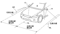
- the right side recognition camera 13 is a fisheye camera built in the right side door mirror as shown in FIG. 2 and has a right side white line lateral position detection function.
- the left side recognition camera 14 is a fisheye camera built in the left side door mirror as shown in FIG. 2 and has a left white line lateral position detection function.
- the right side white line lateral position means the length from the position of the vehicle width direction center line CL of the vehicle A to the inner end position of the right side white line WR.
- the left side white line lateral position means the length from the position of the vehicle width direction center line CL of the vehicle A to the inner end position of the left side white line WL.
- the rider 15 and the radar 16 are disposed at the front end position of the vehicle with the irradiation axis of the output wave directed to the front of the vehicle and receive the reflected wave to detect the presence of an object in front of the vehicle. Detect the distance to the object.
- a rider / radar is configured by combining two types of distance measurement sensors, the rider 15 and the radar 16, and, for example, a laser radar, a millimeter wave radar, an ultrasonic radar, a laser range finder, etc. can be used. With the rider 15 and the radar 16, the position and objects of the vehicle on the road and objects outside the vehicle (road structures, leading vehicles, following vehicles, oncoming vehicles, oncoming vehicles, pedestrians, bicycles, two-wheelers) etc. Detect the distance of
- the rider 15 is provided at the front end left and right position of the vehicle A so as to be able to swing downward rightward and downward leftward downward, and detects right curb lateral position detection function and left curb lateral position detection function And.
- the right side curb lateral position refers to the length from the position of the vehicle width direction center line CL of the vehicle A to the inner end position of the right side curb ER.
- the left side curb lateral position refers to the length from the position of the vehicle width direction center line CL of the vehicle A to the inner end position of the left side curb EL.
- the surrounding environment recognition unit 2 inputs image data from each recognition camera 11, 12, 13, 14 and object data from the rider / radar 15, 16.
- the surrounding environment recognition unit 2 includes a calibration processing unit 21 that generates calibration data of image data and object data, and an object recognition processing unit 22 that performs object recognition processing based on the calibration data.
- the calibration processing unit 21 estimates parameters of the image data from the recognition cameras 11, 12, 13, 14 and parameters of the object data from the rider / radar 15, 16 and uses the parameters to generate image data or an object. Generate and output calibration data of data. For example, in the case of image data from each of the recognition cameras 11, 12, 13, 14, parameters are used to correct the optical axis and lens distortion.
- the object recognition processing unit 22 receives the calibration data from the calibration processing unit 21, performs object recognition processing based on the calibration data, and outputs recognition result data.
- the object recognition processing unit 22 compares, for example, the image data and the object data, and when it is confirmed that the object exists at the position of the object candidate based on the image data, the object recognition processing unit 22 recognizes the presence of the object. Recognize what the object is.
- the navigation control unit 3 inputs the vehicle position information from the GNSS antenna 31, combines the map data including the road information and the GPS (Global Positioning System) using satellite communication, and searches from the current position to the destination by route search Generate a target route for Then, the generated target route is displayed on the map, and the target route information is output.
- GPS Global Positioning System
- GNSS Global Navigation Satellite System: Global Navigation Satellite System
- GPS Global Positioning System
- the automatic driving control unit 4 receives the recognition result data from the object recognition processing unit 22 of the surrounding environment recognition unit 2 and the target route information from the navigation control unit 3. Then, based on the input information, a target vehicle speed, a target acceleration and a target deceleration are generated. Furthermore, the drive control command value is calculated from the generated target acceleration, and the calculation result is output to the drive actuator 51. A braking control command value is calculated based on the generated target deceleration, and the calculation result is output to the braking actuator 52. The steering angle control command value is calculated based on the input target route information, and the calculation result is output to the steering angle actuator 53.
- the actuator 5 has a drive actuator 51, a braking actuator 52, and a steering angle actuator 53.
- the drive actuator 51 is an actuator that receives a drive control command value from the automatic operation control unit 4 and controls the drive source drive force. That is, in the case of an engine car, an engine actuator is used. In the case of a hybrid vehicle, an engine actuator and a motor actuator are used. In the case of an electric vehicle, a motor actuator is used.
- the braking actuator 52 is an actuator that receives a braking control command value from the automatic operation control unit 4 and controls the braking force.
- a hydraulic booster, an electric booster, or the like is used as the brake actuator 52.
- the steering angle actuator 53 is an actuator that receives a steering angle control command value from the automatic operation control unit 4 and controls the turning angle of the steered wheels.
- a steering angle control motor or the like is used as the steering angle actuator 53.
- the navigation control unit 3 includes a GNSS antenna 31, a position information processing unit 32, a destination setting unit 33, a map data storage unit 34, a route search processing unit 35, and a target route correction unit. And a display device 37.
- the position information processing unit 32 performs detection processing of the latitude / longitude of the stop position of the vehicle and the traveling position of the vehicle based on the satellite communication information input from the GNSS antenna 31.
- the vehicle position information from the position information processing unit 32 is output to the route search processing unit 35.
- the destination setting unit 33 performs input setting of the destination of the vehicle by a touch panel operation on the display screen of the display device 37 by the driver or the like.
- the destination information from the destination setting unit 33 is output to the route search processing unit 35.
- the map data storage unit 34 is a storage unit of so-called electronic map data in which the latitude and longitude are associated with the map information.
- the map data has road information associated with each point, and the road information is defined by nodes and links connecting the nodes.
- the road information includes information specifying the road by the position / area of the road, the road type for each road, the road width for each road, and the shape information of the road.
- the road information associates and stores information on the position of the intersection, the approach direction of the intersection, the type of the intersection, and other intersections for each identification information of each road link.
- the road information includes road type, road width, road shape, whether to go straight, whether to advance, whether to overtake (possibility of entering an adjacent lane), speed limit, etc. for each identification information of each road link. Corresponds and stores information on roads in
- the route search processing unit 35 includes the vehicle position information from the position information processing unit 32, the destination information from the destination setting unit 33, and the road map information (road map data) from the map data storage unit 34. input. Then, a target route is generated by route cost calculation or the like based on the road map information.
- the target route may be generated using GPS and a map, but instead of using GPS and a map, when a preceding vehicle is present, the traveling route of the preceding vehicle may be used as the target route. In this case, when the positional accuracy of the GPS is low, by using the travel locus as the target route, the parallel movement amount in the target route correction unit 36 described later can be small, and the vehicle behavior can be made smoother.
- the target path correction unit 36 inputs the recognition result data from the object recognition processing unit 22 and the target path from the route search processing unit 35. Other than the target route, information such as white line lateral distance (left and right), stationary object lateral distance (left and right), curb lateral distance (left and right), usage status of turn signal (winker) by driver, lane change status, vehicle speed etc. Enter Based on the input information, the lane boundary of the lane in which the vehicle travels is detected. Then, the positional relationship between the detected lane boundary and the target route on the map is compared, and if the target route exists within a predetermined distance with respect to the lane boundary, or the target route is with the vehicle relative to the lane boundary If it is on the opposite side, the target path is corrected by lateral translation.
- the "predetermined distance” is a distance that gives the driver a sense of apprehension when the vehicle approaches the lane boundary, and, for example, about 2 m from the center line of the vehicle's width direction to the lane boundary ( The distance from the side of the vehicle to the lane boundary is approximately 1 m.
- the target route is corrected by parallel movement in the lateral direction regardless of the distance to the vehicle.
- the display device 37 inputs the map data information from the map data storage unit 34 and the target route information from the target route corrector 36. Then, the map, the road, the target route, the vehicle position and the destination are displayed on the display screen. That is, the display device 37 provides vehicle position visual information such as where the vehicle is moving on the map during traveling by automatic driving.
- FIG. 4 shows a target path corrector 36 included in the navigation control unit 3 (controller) in the first embodiment.
- the overall configuration of the target path correction unit 36 will be described below based on FIG.
- the target route correction unit 36 sets a navigation error that occurs between the vehicle position and the target route when the vehicle position detected using the navigation information is superimposed on the map information while traveling by automatic driving, Correct by horizontal and parallel movement.
- the target route correction unit 36 includes a road boundary information integration unit 361 (lane boundary detection unit), a horizontal correction amount calculation unit 362, and a horizontal parallel movement unit 363.
- the road boundary information integration unit 361 is a white line lateral distance (left and right), a stationary object lateral distance (left and right), a curb lateral distance (left and right), a use condition of a turn indicator (winker) by a driver, a lane change condition, a vehicle speed Enter information such as Then, the lane boundary of the lane in which the host vehicle A travels is detected, and the lateral distance (left and right) between the host vehicle A and the lane boundary is output to the lateral correction amount calculation unit 362.
- the lateral correction amount calculation unit 362 includes the target route from the route search processing unit 35, the lane boundary lateral distance (left and right) from the road boundary information integration unit 361, the use status of the turn signal by the driver, the lane change status, Input information such as vehicle speed. Then, the positional relationship between the detected lane boundary and the target route on the map is compared, and if the target route exists within a predetermined distance with respect to the lane boundary, or if the target route is the vehicle A with the lane boundary Calculates the lateral correction amount of the target route when it exists on the opposite side.
- the horizontal parallel movement unit 363 inputs the target path from the route search processing unit 35 and the horizontal correction amount from the horizontal correction amount calculation unit 362. Then, when the horizontal correction amount is calculated, as shown in the lower right frame B of FIG. 4, the target route is corrected by the horizontal parallel displacement by the horizontal correction amount to generate a new target route.
- the parallel movement correction of the target route when the traveling direction of the host vehicle A and the target route are deviated, the matching between the traveling direction of the host vehicle A and the new target route is enhanced.
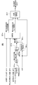
- FIG. 5 shows the road boundary information integration unit 361 of the target route correction unit 36
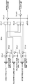
- FIG. 6 shows the arbitration unit 361 e of the road boundary information integration unit 361.
- the detailed configuration of the road boundary information integration unit 361 will be described based on FIGS. 5 and 6.
- the road boundary information integration unit 361 includes an OR circuit 361a, a selector 361b, a road boundary adjustment unit 361c, an adjustment amount adder 361d, an arbitration unit 361e, and a one side loss complementation unit 361f. And.
- the selector 361b selects zero (fixed value) as the lateral distance adjustment amount when the driver does not input the use state of the direction indicator by the driver via the OR circuit 361a or the lane change state.
- a lateral distance adjustment amount that gradually reduces the parallel movement amount of the target route is given. That is, when the target route is moved in parallel in the lateral direction, when the steering operation intervenes by the driver, the parallel movement amount of the target route is gradually decreased, and the steering operation intervention by the driver is determined by the blinker operation by the driver. There is.
- the road boundary adjustment unit 361c inputs a lateral distance adjustment amount such that the lateral distance increases and the parallel movement correction amount of the target route decreases as the vehicle speed increases.
- the adjustment amount adder 361 d adds the lateral direction distance adjustment amount from the selector 361 b and the lateral direction distance adjustment amount from the road boundary adjustment unit 361 c, and uses this as the adjustment amount in the arbitration unit 361 e.
- the arbitration unit 361 e receives the horizontal line lateral distance (left and right), the stationary object lateral direction (left and right), the curb lateral distance (left and right), and the lateral distance adjustment amount from the adjustment amount adder 361 d. Then, the post-mediation road boundary left direction distance and the post-mediation road boundary right direction distance are output. Details of the arbitration unit 361 e will be described later.
- the one-sided loss time complementation unit 361 f inputs the post-mediation road boundary left direction distance, the post-mediation road boundary right direction distance, and the vehicle speed. Then, when a part of the lateral distance information on one side of the post-mediation road boundary left direction distance and the post-mediation road boundary right direction distance is lost, the lateral distance information on the lost side is complemented by the vehicle speed. Output the boundary lateral distance (left and right).
- the road is detected within a range of a predetermined distance that changes according to the vehicle speed of the vehicle.
- a detection value based on the road end closest to the vehicle is used as lane boundary information. This complements the lost lateral distance information.
- the arbitration unit 361e includes subtractors 361e1, 361e2, 361e3, adders 361e4, 361e5, 361e6, minimum value selector 361e7, maximum value selector 361e8, and final subtractor 361e9. And a final adder 361e10.
- the subtractor 361e1 and the adder 361e4 of the white line lateral distance are set to zero (fixed value) as the white line lateral direction distance adjustment amount. That is, the "white line” is recognized as the lane end of the target route of the vehicle, and the lateral distance adjustment is not performed.
- the subtractor 361e2 and the adder 361e5 of the stationary object lateral direction distance have predetermined values (fixed values) as the stationary object lateral direction distance adjustment amount. That is, the "stationary object" is recognized as the road edge on which the vehicle travels, and lateral distance adjustment is performed to acquire lane edge information from the road edge. In other words, when detecting the lane boundary of the lane in which the host vehicle is traveling, if the position of the road end (stationary object) is detected, the inward position of a predetermined width from the detected road end (stationary object) Use as information.
- the curb lateral distance (left and right) subtractor 361 e 3 and the adder 361 e 6 have predetermined values (fixed values) as the curb lateral distance adjustment amount. That is, “curb” is recognized as the road edge on which the vehicle travels, and lateral distance adjustment is performed to acquire lane edge information from the road edge. In other words, when detecting the lane boundary of the lane in which the vehicle travels, if the position of the road edge (curb) is detected, the inside position of a predetermined width from the detected road edge (curb) is used as lane boundary information use.
- the minimum value selector 361 e 7 is a white line lateral distance (left) having passed the subtractor 361 e 2, a stationary object lateral direction distance (left) having passed the subtractor 361 e 2, and a curb stone lateral distance (left ), And select the minimum value as the road boundary left direction distance. That is, when detecting the lane boundary of the lane in which the vehicle travels, if both the position of the lane boundary (white line position) and the position of the road end (stationary object position or curb position) are detected, the inner side closer to the vehicle The detected position value is used as lane boundary information.
- the maximum value selector 361 e 8 is a white line lateral distance (right) passed by the adder 361 e 4, a stationary object lateral distance (right) passed by the adder 361 e 5, and a curb stone lateral distance passed by the adder 361 e 6 (right ), And select the maximum value as the road boundary right direction distance.
- the final subtractor 361 e 9 subtracts the adjustment amount from the adjustment amount adder 361 d from the road boundary left direction distance from the minimum value selector 361 e 7 to obtain an adjusted road boundary left direction distance.
- the final adder 361 e 10 adds the adjustment amount from the adjustment amount adder 361 d from the road boundary right direction distance from the maximum value selector 361 e 8 to obtain an adjusted road boundary right direction distance.
- FIG. 7 shows the lateral correction amount calculation unit 362 of the target path correction unit 36.
- the detailed configuration of the lateral correction amount calculating unit 362 will be described based on FIG. 7.
- the lateral correction amount calculator 362 includes a lateral deviation calculator 362a, a positional relationship understanding unit 362b, a lateral correction amount calculator 362c, a change rate maximum value determiner 362d, and a rate limiter 362e. And.
- the lateral deviation calculation unit 362a receives the target route from the route search processing unit 35, and calculates the lateral deviation Y0 between the target route and the vehicle.
- the positional relationship understanding unit 362 b inputs the lateral deviation Y 0 from the lateral deviation calculation unit 362 a and the lane boundary lateral distance (left and right) from the road boundary information integration unit 361. Then, the positional relationship between the target route and the lane boundary is understood (understood) by comparing the positional relationship between the target route and the lane edge. At this time, when the target route exists within a predetermined distance with respect to the lane boundary (left) or when the target route exists on the opposite side of the vehicle with respect to the lane boundary (left), the left boundary detection state Output (flag). On the other hand, when the target route exists within a predetermined distance with respect to the lane boundary (right) or when the target route exists on the opposite side of the vehicle with respect to the lane boundary (right), Output the flag).
- the lateral correction amount calculation unit 362c inputs the left boundary detection situation (flag) and the right boundary detection situation (flag) from the positional relationship understanding unit 362b, and the lane boundary lateral distance (left and right) from the road boundary information integration unit 361. Do. Then, the lateral correction amount of the target route is calculated so that the position of the target route coincides with the position of the vehicle, and the calculation result is output as a lateral correction amount target value.
- the change rate maximum value determination unit 362d inputs the use condition of the direction indicator by the driver, the lane change condition, the vehicle speed, the left boundary detection condition (flag), and the right boundary detection condition (flag). Then, the lower limit value and the upper limit value of the lateral correction amount change rate (moving speed of the target route) are determined. That is, when the change rate maximum value determination unit 362d corrects the target route by the parallel movement in the horizontal direction, the change rate maximum value determination unit 362d only specifies the moving speed (horizontal correction amount change rate) of the target route parallelly moved in the horizontal direction to a predetermined speed. Rather, it has the function of defining it variably according to the situation. The configuration of the change rate maximum value determination unit 362d will be described in detail later.
- the rate limiter 362 e receives the horizontal correction amount target value from the change rate maximum value determination unit 362 d and the horizontal correction amount change rate lower limit value and the horizontal correction amount change rate upper limit value from the change rate maximum value determination unit 362 d. Then, the lateral correction amount target value is restricted by the lateral correction amount change rate (the moving speed of the target route) to obtain a lateral correction amount.
- the change rate maximum value determination unit 362d includes a low vehicle speed change suppression unit 362d1, a first rate switching unit 362d2, a second rate switching unit 362d3, a third rate switching unit 362d4, and a fourth rate switching unit 362d5.
- a first rate integration unit 362d6 and a second rate integration unit 362d7 are provided.
- the low vehicle speed change suppressing portion 362d1 inputs the vehicle speed, and determines the vehicle speed corresponding change rate so as to decrease the moving speed of the target route according to the vehicle speed decrease, when the vehicle speed of the own vehicle decreases. Then, when the vehicle stops, the change rate corresponding to the vehicle speed is made zero.
- the first rate switching unit 362d2 uses the lane change situation as a trigger to select a vehicle speed-compatible change rate in a normal traveling scene without a lane change, and switches the change rate to zero when the lane change situation is input.
- the third rate switching unit 362d4 uses the right boundary detection state (flag) as a trigger to switch between a large rate (fixed value) and a small rate (fixed value).
- the fourth rate switching unit 362d5 uses the left boundary detection state (flag) as a trigger to switch between a large rate (fixed value) and a small rate (fixed value).
- the first rate integration unit 362d6 receives the change rate from the second rate switching unit 362d3 and the change rate from the third rate switching unit 362d4, and calculates the lateral correction amount change rate upper limit value by integrating both change rates. .
- the second rate integration unit 362d7 receives the change rate from the second rate switching unit 362d3 and the change rate from the fourth rate switching unit 362d5, and calculates the lateral correction amount change rate upper limit value by integrating both change rates. .
- the change rate maximum value determination unit 362d controls the moving speed (change rate) of the target route listed below.
- the operation of the first embodiment will be described by dividing it into “target route correction operation”, “vehicle behavior contrast operation at the time of entering a narrow lane,” and “vehicle behavior contrast operation at the time of entering a wide lane”.
- FIG. 8 shows the target path correction operation performed by the target path correction unit 36 of the navigation control unit 3.
- the target path correction operation will be described based on FIG.
- the navigation control unit 3 is provided to correct an error generated between the vehicle position and the target route when the vehicle position detected using the navigation information is superimposed on the map information during automatic driving and traveling.
- the navigation control unit 3 has a target path corrector 36 that corrects the target path.
- the target route correction unit 36 includes a road boundary information integration unit 361, a lateral correction amount calculation unit 362, and a lateral parallel movement unit 363.
- the road boundary information integration unit 361 detects the lane boundary of the lane in which the host vehicle A travels. That is, as shown in FIG. 8, the right side white line WR is detected as a lane boundary by the right side recognition camera 13. The riders 15 and 15 detect the curb ER on the right side road edge and the curb EL on the left side road edge as the road edge. Therefore, in the case shown in FIG. 8, the right lane boundary is located inside the right white line WR, and the left lane boundary is located closer to the vehicle A side from the inside of the curb EL.
- the lateral correction amount calculation unit 362 the positional relationship between the detected left lane boundary and the right lane boundary and the target route TL on the map is compared.
- the distance between the target route TL and the left lane boundary is short while the distance between the target route TL and the right lane boundary is sufficiently large. Therefore, based on the determination that the target route TL exists within a predetermined distance from the left lane boundary, the lateral correction amount calculation unit 362 sets the target route TL to the right in FIG. 8 as the lateral correction amount LO of the target route TL. The amount of offset is calculated.
- FIG. 9 shows the vehicle behavior of the comparative example when entering a narrow lane and the vehicle behavior of Example 1 among the target route correction action.
- the vehicle behavior contrast action at the time of a narrow lane entry will be described.
- a navigation example in which the navigation error occurring between the vehicle position and the target route is performed by the self position correction of the vehicle is taken as a comparative example.
- the vehicle A travels along the traveling line E which is substantially the same as the traveling line D.
- FIG. 10 shows the vehicle behavior of the comparative example at the time of entering a wide lane and the vehicle behavior of Example 1 among the target route correction functions.
- the vehicle behavior contrast action at the time of a narrow lane entry will be described.
- a navigation example in which the navigation error occurring between the vehicle position and the target route is performed by the self position correction of the vehicle is taken as a comparative example.
- a wide lane entry scene is obtained from a road without left and right white lines WL, WR suddenly with wide lateral widths L2 (> L1) of left and right white lines WL, WR.
- L2 wide lateral widths
- the host vehicle A's vehicle A's lateral position is promptly returned to the lane center. Self position correction is made. For this reason, in the case of the comparative example, the vehicle A travels along the traveling line D.
- the target route is selected.
- the parallel movement speed for slowly returning to the lane center side makes it possible to make a correction for laterally moving the target path in the lateral direction.
- the vehicle A travels along the traveling line E ′ in which the vehicle lateral G is suppressed to a small value, unlike the traveling line D.
- a controller (navigation control unit 3) that corrects an error that occurs between the vehicle position and the target route during driving assistance traveling (during automatic driving traveling).
- the position error correction method of the driving support vehicle automated driving vehicle
- the lane boundary of the lane in which the vehicle travels is detected.
- the positional relationship between the detected lane boundary and the target route on the map is compared, and if the target route exists within a predetermined distance with respect to the lane boundary, or the target route is opposite to the host vehicle with respect to the lane boundary If so, the target path is corrected by lateral translation (FIG. 8). For this reason, it is possible to select whether to give priority to smoothness or to give priority not to protrude according to the scene, and position error correction of a driving support vehicle (automatic driving vehicle) that realizes more reliable vehicle behavior. We can provide a way.
- the moving speed of the target route to be translated in the lateral direction is defined as a predetermined velocity (FIG. 7). Therefore, in addition to the effects of (1) to (4), the vehicle behavior of the own vehicle can be made smooth by defining the moving speed of the target route to be moved in parallel in the lateral direction to a predetermined speed.
- a controller (navigation control unit 3) which corrects an error occurring between the vehicle position and the target route during driving assistance traveling (during automatic driving traveling).
- the controller has a target route correction unit 36 that corrects the target route.
- the target route correction unit 36 includes a lane boundary detection unit (road boundary information integration unit 361), a lateral correction amount calculation unit 362, and a lateral parallel movement unit 363.
- the lane boundary detection unit (road boundary information integration unit 361) detects the lane boundary of the lane in which the vehicle travels.
- the lateral correction amount calculation unit 362 compares the positional relationship between the detected lane boundary and the target route on the map, and if the target route exists within a predetermined distance from the lane boundary, or the target route is at the lane boundary. On the other hand, when the vehicle is on the opposite side, the lateral correction amount of the target route is calculated. When the horizontal correction amount is calculated, the horizontal parallel movement unit 363 corrects the target path by the horizontal parallel movement by the horizontal correction amount (FIG. 4). For this reason, it is possible to select whether to give priority to smoothness or to give priority not to protrude according to the scene, and position error correction of a driving support vehicle (automatic driving vehicle) that realizes more reliable vehicle behavior.
- An apparatus can be provided.
- the navigation control unit 3 is used as a controller that generates a target route from the current position of the vehicle to the destination.
- a controller that generates a target route from the current position of the host vehicle to the destination an example may be taken as an automatic driving control unit.
- the target route generation function may be divided into two, a part may be divided by the navigation control unit, and the remaining part may be divided by the automatic driving control unit.
- the first embodiment shows an example in which the position error correction method and the position error correction device of the present disclosure are applied to an automatically driven vehicle in which steering / driving / braking is automatically controlled by selection of the automatic driving mode.
- the position error correction method and the position error correction device according to the present disclosure may be a driving support vehicle that supports part of driving among steering driving / driving driving / braking driving by a driver.
- the present invention can be applied to any vehicle that assists the driver in driving by correcting an error that occurs between the vehicle position and the target route.
Abstract
Priority Applications (10)
| Application Number | Priority Date | Filing Date | Title |
|---|---|---|---|
| EP17923515.5A EP3678109B1 (fr) | 2017-08-30 | 2017-08-30 | Procédé de correction de position pour véhicule d'aide à la conduite et dispositif de correction d'erreur de position |
| PCT/JP2017/031166 WO2019043831A1 (fr) | 2017-08-30 | 2017-08-30 | Procédé de correction de position pour véhicule d'aide à la conduite et dispositif de correction d'erreur de position |
| MX2020002171A MX2020002171A (es) | 2017-08-30 | 2017-08-30 | Metodo de correccion de posicion y dispositivo de correccion de error de posicion para vehiculo de conduccion asistida. |
| CN201780094048.5A CN111033593B (zh) | 2017-08-30 | 2017-08-30 | 驾驶辅助车辆的位置误差校正方法及位置误差校正装置 |
| KR1020207006826A KR20200030617A (ko) | 2017-08-30 | 2017-08-30 | 운전 지원 차량의 위치 오차 보정 방법 및 위치 오차 보정 장치 |
| RU2020112174A RU2741529C1 (ru) | 2017-08-30 | 2017-08-30 | Способ коррекции положения и устройство коррекции ошибки положения для транспортного средства с поддержкой вождения |
| JP2019538819A JP6642772B2 (ja) | 2017-08-30 | 2017-08-30 | 運転支援車両の位置誤差補正方法及び位置誤差補正装置 |
| CA3074413A CA3074413A1 (fr) | 2017-08-30 | 2017-08-30 | Procede de correction de position pour vehicule d'aide a la conduite et dispositif de correction d'erreur de position |
| BR112020004099-1A BR112020004099A2 (pt) | 2017-08-30 | 2017-08-30 | método de correção de posição e dispositivo de correção de erro de posição para veículos auxiliados por condução |
| US16/638,791 US11167758B2 (en) | 2017-08-30 | 2017-08-30 | Vehicle position correction method and vehicle position correction device for drive-assisted vehicle |
Applications Claiming Priority (1)
| Application Number | Priority Date | Filing Date | Title |
|---|---|---|---|
| PCT/JP2017/031166 WO2019043831A1 (fr) | 2017-08-30 | 2017-08-30 | Procédé de correction de position pour véhicule d'aide à la conduite et dispositif de correction d'erreur de position |
Publications (1)
| Publication Number | Publication Date |
|---|---|
| WO2019043831A1 true WO2019043831A1 (fr) | 2019-03-07 |
Family
ID=65526453
Family Applications (1)
| Application Number | Title | Priority Date | Filing Date |
|---|---|---|---|
| PCT/JP2017/031166 WO2019043831A1 (fr) | 2017-08-30 | 2017-08-30 | Procédé de correction de position pour véhicule d'aide à la conduite et dispositif de correction d'erreur de position |
Country Status (10)
| Country | Link |
|---|---|
| US (1) | US11167758B2 (fr) |
| EP (1) | EP3678109B1 (fr) |
| JP (1) | JP6642772B2 (fr) |
| KR (1) | KR20200030617A (fr) |
| CN (1) | CN111033593B (fr) |
| BR (1) | BR112020004099A2 (fr) |
| CA (1) | CA3074413A1 (fr) |
| MX (1) | MX2020002171A (fr) |
| RU (1) | RU2741529C1 (fr) |
| WO (1) | WO2019043831A1 (fr) |
Cited By (4)
| Publication number | Priority date | Publication date | Assignee | Title |
|---|---|---|---|---|
| JP2021020475A (ja) * | 2019-07-24 | 2021-02-18 | 株式会社Subaru | 車両の自動運転支援装置 |
| CN112455435A (zh) * | 2019-09-06 | 2021-03-09 | 丰田自动车株式会社 | 驾驶辅助装置 |
| CN113924225A (zh) * | 2019-05-29 | 2022-01-11 | 大众汽车股份公司 | 用于通过机动车辆中的驾驶员辅助系统对行驶方向执行修正的方法以及用于此的控制设备 |
| JP7469896B2 (ja) | 2020-02-06 | 2024-04-17 | 本田技研工業株式会社 | 周辺認識装置、周辺認識方法、およびプログラム |
Families Citing this family (21)
| Publication number | Priority date | Publication date | Assignee | Title |
|---|---|---|---|---|
| KR102055156B1 (ko) * | 2018-02-05 | 2019-12-12 | 주식회사 만도 | 적응형 순항 제어 시스템의 제어 장치 및 제어 방법 |
| CN110018632B (zh) * | 2018-06-22 | 2020-10-09 | 长城汽车股份有限公司 | 一种车辆变道控制方法和装置 |
| RU2758918C1 (ru) * | 2018-09-07 | 2021-11-03 | Ниссан Мотор Ко., Лтд. | Способ управления движением транспортного средства и устройство управления движением |
| US11120277B2 (en) * | 2018-10-10 | 2021-09-14 | Denso Corporation | Apparatus and method for recognizing road shapes |
| JP7257814B2 (ja) * | 2019-02-21 | 2023-04-14 | 日立Astemo株式会社 | 走行路認識装置 |
| US11243081B2 (en) * | 2019-03-29 | 2022-02-08 | Trimble Inc. | Slam assisted INS |
| JP7247849B2 (ja) * | 2019-10-11 | 2023-03-29 | トヨタ自動車株式会社 | 駐車支援装置 |
| US11543263B1 (en) * | 2020-09-16 | 2023-01-03 | Zoox, Inc. | Map distortion determination |
| CN114252883B (zh) * | 2020-09-24 | 2022-08-23 | 北京万集科技股份有限公司 | 目标检测方法、装置、计算机设备和介质 |
| CN112537298A (zh) * | 2020-11-30 | 2021-03-23 | 南通路远科技信息有限公司 | 一种车道的自动生成方法、装置及交通载具 |
| CN112537299A (zh) * | 2020-11-30 | 2021-03-23 | 南通路远科技信息有限公司 | 一种基于目标物的车道保持方法、装置及交通载具 |
| CN112896879B (zh) * | 2021-02-24 | 2022-11-18 | 同济大学 | 一种用于智能环卫车的环境感知系统 |
| US11845428B2 (en) * | 2021-07-13 | 2023-12-19 | Canoo Technologies Inc. | System and method for lane departure warning with ego motion and vision |
| US11840147B2 (en) | 2021-07-13 | 2023-12-12 | Canoo Technologies Inc. | System and method in data-driven vehicle dynamic modeling for path-planning and control |
| US11908200B2 (en) | 2021-07-13 | 2024-02-20 | Canoo Technologies Inc. | System and method in the prediction of target vehicle behavior based on image frame and normalization |
| US11891059B2 (en) | 2021-07-13 | 2024-02-06 | Canoo Technologies Inc. | System and methods of integrating vehicle kinematics and dynamics for lateral control feature at autonomous driving |
| US11891060B2 (en) | 2021-07-13 | 2024-02-06 | Canoo Technologies Inc. | System and method in lane departure warning with full nonlinear kinematics and curvature |
| CN113882201B (zh) * | 2021-09-09 | 2022-07-01 | 华中科技大学 | 一种自动驾驶车辆专用车道直线段宽度确定方法 |
| CN113779174B (zh) * | 2021-11-05 | 2022-04-01 | 华砺智行(武汉)科技有限公司 | 提高路侧传感器感知精度的方法、系统、设备及介质 |
| US20230150494A1 (en) * | 2021-11-16 | 2023-05-18 | GM Global Technology Operations LLC | System and methods for engagement in hands-off lane centering applications |
| CN114565904A (zh) * | 2022-03-02 | 2022-05-31 | 北京百度网讯科技有限公司 | 确定可行驶区域的方法、装置、设备、介质和车辆 |
Citations (3)
| Publication number | Priority date | Publication date | Assignee | Title |
|---|---|---|---|---|
| JP2015205635A (ja) * | 2014-04-22 | 2015-11-19 | 本田技研工業株式会社 | 走行支援装置 |
| JP2016151864A (ja) * | 2015-02-17 | 2016-08-22 | トヨタ自動車株式会社 | 車線追従制御装置 |
| JP2017013586A (ja) | 2015-06-30 | 2017-01-19 | 富士重工業株式会社 | 自車位置推定装置、及びそれを用いた操舵制御装置、並びに自車位置推定方法 |
Family Cites Families (74)
| Publication number | Priority date | Publication date | Assignee | Title |
|---|---|---|---|---|
| DE19507957C1 (de) * | 1995-03-07 | 1996-09-12 | Daimler Benz Ag | Fahrzeug mit optischer Abtasteinrichtung für einen seitlichen Fahrbahnbereich |
| JP4092308B2 (ja) * | 2004-06-02 | 2008-05-28 | トヨタ自動車株式会社 | 境界線検出装置 |
| DE102005025387A1 (de) | 2004-09-30 | 2006-05-04 | Daimlerchrysler Ag | Verfahren und Vorrichtung zur Fahrerwahrnung bzw. zum aktiven Eingreifen in die Fahrdynamik, falls ein Verlassen der Fahrspur droht |
| US7708493B2 (en) * | 2005-08-26 | 2010-05-04 | Searete, Llc | Modifiable display marker |
| JP5162103B2 (ja) | 2006-05-15 | 2013-03-13 | トヨタ自動車株式会社 | 支援制御装置 |
| GB2448470B (en) | 2007-04-20 | 2012-04-04 | Ultra Global Ltd | Vehicle guidance system |
| JP2008286671A (ja) * | 2007-05-18 | 2008-11-27 | Alpine Electronics Inc | 車載用ナビゲーション装置 |
| DE102009009211A1 (de) * | 2008-02-20 | 2009-09-10 | Continental Teves Ag & Co. Ohg | Verfahren und Assistenzsystem zum Erfassen von Objekten im Umfeld eines Fahrzeugs |
| US8111147B2 (en) * | 2008-05-13 | 2012-02-07 | GM Global Technology Operations LLC | Lane departure warning and change assist system utilizing active materials |
| DE112009001440B4 (de) * | 2008-06-11 | 2014-01-09 | Mitsubishi Electric Corp. | Navigationsvorrichtung und Kartendaten-Verarbeitungsverfahren |
| US8428843B2 (en) * | 2008-06-20 | 2013-04-23 | GM Global Technology Operations LLC | Method to adaptively control vehicle operation using an autonomic vehicle control system |
| DE112009001539B4 (de) * | 2008-07-04 | 2014-01-02 | Mitsubishi Electric Corporation | Kartenanzeigevorrichtung |
| CN102202948B (zh) * | 2008-10-28 | 2014-05-07 | 株式会社爱德克斯 | 用于控制车辆行驶的设备 |
| US8831876B2 (en) * | 2009-12-28 | 2014-09-09 | Clarion Co., Ltd. | Navigation device, route guidance method, and program |
| WO2012011156A1 (fr) * | 2010-07-23 | 2012-01-26 | 三菱電機株式会社 | Dispositif de navigation |
| JP5630583B2 (ja) * | 2011-08-31 | 2014-11-26 | 日産自動車株式会社 | 車両運転支援装置 |
| JP5966965B2 (ja) * | 2013-02-19 | 2016-08-10 | 株式会社デンソー | 車線境界線逸脱抑制装置及び車線境界線逸脱抑制方法 |
| MX345983B (es) * | 2013-06-28 | 2017-03-01 | Nissan Motor | Dispositivo de control de direccion. |
| KR101502510B1 (ko) * | 2013-11-26 | 2015-03-13 | 현대모비스 주식회사 | 차량의 차선 유지 제어 장치 및 방법 |
| KR101502511B1 (ko) * | 2013-11-28 | 2015-03-13 | 현대모비스 주식회사 | 가상 차선 생성 장치와 방법 및 상기 장치를 구비하는 차선 유지 제어 시스템 |
| JP6241341B2 (ja) * | 2014-03-20 | 2017-12-06 | アイシン・エィ・ダブリュ株式会社 | 自動運転支援装置、自動運転支援方法及びプログラム |
| CN103954275B (zh) * | 2014-04-01 | 2017-02-08 | 西安交通大学 | 基于车道线检测和gis地图信息开发的视觉导航方法 |
| JP6130809B2 (ja) * | 2014-04-25 | 2017-05-17 | 本田技研工業株式会社 | 車線認識装置 |
| KR101551096B1 (ko) * | 2014-06-05 | 2015-09-21 | 현대자동차주식회사 | 자율주행차량의 차선변경장치 및 방법 |
| JP6375754B2 (ja) * | 2014-07-25 | 2018-08-22 | アイシン・エィ・ダブリュ株式会社 | 自動運転支援システム、自動運転支援方法及びコンピュータプログラム |
| US9862382B2 (en) * | 2014-08-11 | 2018-01-09 | Nissan Motor Co., Ltd. | Travel control device and method for vehicle |
| RU2659371C1 (ru) * | 2014-08-29 | 2018-06-29 | Ниссан Мотор Ко., Лтд. | Устройство управления движением и способ управления движением |
| US9499197B2 (en) * | 2014-10-15 | 2016-11-22 | Hua-Chuang Automobile Information Technical Center Co., Ltd. | System and method for vehicle steering control |
| JP6086106B2 (ja) * | 2014-10-16 | 2017-03-01 | トヨタ自動車株式会社 | 運転支援装置 |
| JP2016084092A (ja) * | 2014-10-28 | 2016-05-19 | 富士重工業株式会社 | 車両の走行制御装置 |
| JP6123812B2 (ja) * | 2015-01-29 | 2017-05-10 | トヨタ自動車株式会社 | 車線追従制御装置 |
| JP6344275B2 (ja) * | 2015-03-18 | 2018-06-20 | トヨタ自動車株式会社 | 車両制御装置 |
| JP6350383B2 (ja) * | 2015-05-01 | 2018-07-04 | トヨタ自動車株式会社 | 車両走行制御装置 |
| KR102484148B1 (ko) * | 2015-06-03 | 2023-01-03 | 클리어모션, 아이엔씨. | 차체 모션 및 승객 경험을 제어하기 위한 방법 및 시스템 |
| JP6376055B2 (ja) * | 2015-06-26 | 2018-08-22 | 株式会社デンソー | 車線逸脱抑制システム |
| US9821801B2 (en) * | 2015-06-29 | 2017-11-21 | Mitsubishi Electric Research Laboratories, Inc. | System and method for controlling semi-autonomous vehicles |
| JP2017052413A (ja) * | 2015-09-09 | 2017-03-16 | 株式会社デンソー | 車両制御装置 |
| JP6055528B1 (ja) * | 2015-09-25 | 2016-12-27 | 富士重工業株式会社 | 車両の操舵制御装置 |
| JP6815724B2 (ja) * | 2015-11-04 | 2021-01-20 | トヨタ自動車株式会社 | 自動運転システム |
| US9731755B1 (en) * | 2016-02-16 | 2017-08-15 | GM Global Technology Operations LLC | Preview lateral control for automated driving |
| JP6246844B2 (ja) * | 2016-02-18 | 2017-12-13 | 本田技研工業株式会社 | 車両制御システム、車両制御方法、および車両制御プログラム |
| JP6308233B2 (ja) * | 2016-02-29 | 2018-04-11 | トヨタ自動車株式会社 | 車両制御装置及び車両制御方法 |
| JP2017165156A (ja) * | 2016-03-14 | 2017-09-21 | 本田技研工業株式会社 | 車両制御システム、車両制御方法、および車両制御プログラム |
| JP6380766B2 (ja) * | 2016-03-14 | 2018-08-29 | 本田技研工業株式会社 | 車両制御装置、車両制御方法、および車両制御プログラム |
| JP2017182521A (ja) * | 2016-03-31 | 2017-10-05 | 日立オートモティブシステムズ株式会社 | 車両用走行制御装置 |
| US10384672B1 (en) * | 2016-05-11 | 2019-08-20 | Apple Inc. | Vehicle stability control system |
| US9910440B2 (en) * | 2016-05-13 | 2018-03-06 | Delphi Technologies, Inc. | Escape-path-planning system for an automated vehicle |
| US10303166B2 (en) * | 2016-05-23 | 2019-05-28 | nuTonomy Inc. | Supervisory control of vehicles |
| JP6382887B2 (ja) * | 2016-06-03 | 2018-08-29 | 本田技研工業株式会社 | 走行制御装置 |
| JP2018020682A (ja) * | 2016-08-04 | 2018-02-08 | トヨタ自動車株式会社 | 車両制御装置 |
| JP6583183B2 (ja) * | 2016-08-04 | 2019-10-02 | トヨタ自動車株式会社 | 車両制御装置 |
| US20180188031A1 (en) * | 2016-08-31 | 2018-07-05 | Faraday&Future Inc. | System and method for calibrating vehicle dynamics expectations for autonomous vehicle navigation and localization |
| US20190266890A1 (en) * | 2016-10-20 | 2019-08-29 | Ford Motor Company | Methods and apparatus for presenting lane and vehicle type-specific traffic information on a map |
| KR101906197B1 (ko) * | 2016-11-07 | 2018-12-05 | 엘지전자 주식회사 | 차량 및 그 제어방법 |
| EP3324330A1 (fr) * | 2016-11-16 | 2018-05-23 | Continental Automotive GmbH | Procédé de détermination du tracé de routes, système d'assistance au conducteur et véhicule |
| US10518776B2 (en) * | 2017-01-18 | 2019-12-31 | Denso International America, Inc. | Vehicle system, vehicle controller, and method of controlling vehicle |
| US10279807B2 (en) * | 2017-02-17 | 2019-05-07 | GM Global Technology Operations LLC | System and method for predicting a possible lane departure when driving a vehicle autonomously or semi-autonomously, and for taking a remedial action to prevent a lane departure |
| JP2018136700A (ja) * | 2017-02-21 | 2018-08-30 | トヨタ自動車株式会社 | 車両の制御装置 |
| US11193782B2 (en) * | 2017-03-27 | 2021-12-07 | Mitsubishi Electric Corporation | Vehicle position estimation apparatus |
| US10814913B2 (en) * | 2017-04-12 | 2020-10-27 | Toyota Jidosha Kabushiki Kaisha | Lane change assist apparatus for vehicle |
| US10710588B2 (en) * | 2017-05-23 | 2020-07-14 | Toyota Motor Engineering & Manufacturing North America, Inc. | Merging and lane change acceleration prediction energy management |
| DE102017211600A1 (de) * | 2017-07-07 | 2019-01-10 | Volkswagen Aktiengesellschaft | Verfahren und Vorrichtung zum Anzeigen von Spurinformationen in einem Fahrzeug |
| MX2020002227A (es) * | 2017-08-30 | 2020-07-14 | Nissan Motor | Metodo para corregir error de posicion y dispositivo para corregir error de posicion en vehiculo de conduccion asistida. |
| JP6747597B2 (ja) * | 2017-08-30 | 2020-08-26 | 日産自動車株式会社 | 運転支援車両の走行制御方法及び走行制御装置 |
| WO2019049323A1 (fr) * | 2017-09-08 | 2019-03-14 | 日産自動車株式会社 | Procédé d'aide à la conduite et dispositif d'aide à la conduite |
| JP7072581B2 (ja) * | 2017-09-18 | 2022-05-20 | バイドゥドットコム タイムズ テクノロジー (ベイジン) カンパニー リミテッド | 自動運転車両の経路計画のための運転シナリオに基づく車線ガイドライン |
| JP6939334B2 (ja) * | 2017-09-27 | 2021-09-22 | トヨタ自動車株式会社 | 運転支援装置 |
| EP3569460B1 (fr) * | 2018-04-11 | 2024-03-20 | Hyundai Motor Company | Appareil et procédé de contrôle de la conduite dans un véhicule |
| JP7048398B2 (ja) * | 2018-04-13 | 2022-04-05 | 本田技研工業株式会社 | 車両制御装置、車両制御方法、およびプログラム |
| US11287814B2 (en) * | 2018-08-07 | 2022-03-29 | GM Global Technology Operations LLC | Lane change detection system and method for an autonomous vehicle |
| JP7229710B2 (ja) * | 2018-09-26 | 2023-02-28 | 本田技研工業株式会社 | 車両制御装置、車両制御方法、およびプログラム |
| US11518384B2 (en) * | 2018-12-07 | 2022-12-06 | Thinkware Corporation | Method for displaying lane information and apparatus for executing the method |
| US11186282B2 (en) * | 2018-12-11 | 2021-11-30 | Alpine Electronics, Inc. | Automated lane change system and methods |
| US20200307589A1 (en) * | 2019-03-29 | 2020-10-01 | Chongqing Jinkang New Energy Vehicle, Ltd. | Automatic lane merge with tunable merge behaviors |
-
2017
- 2017-08-30 MX MX2020002171A patent/MX2020002171A/es unknown
- 2017-08-30 CN CN201780094048.5A patent/CN111033593B/zh active Active
- 2017-08-30 BR BR112020004099-1A patent/BR112020004099A2/pt unknown
- 2017-08-30 JP JP2019538819A patent/JP6642772B2/ja active Active
- 2017-08-30 CA CA3074413A patent/CA3074413A1/fr not_active Abandoned
- 2017-08-30 KR KR1020207006826A patent/KR20200030617A/ko not_active Application Discontinuation
- 2017-08-30 WO PCT/JP2017/031166 patent/WO2019043831A1/fr unknown
- 2017-08-30 US US16/638,791 patent/US11167758B2/en active Active
- 2017-08-30 RU RU2020112174A patent/RU2741529C1/ru active
- 2017-08-30 EP EP17923515.5A patent/EP3678109B1/fr active Active
Patent Citations (3)
| Publication number | Priority date | Publication date | Assignee | Title |
|---|---|---|---|---|
| JP2015205635A (ja) * | 2014-04-22 | 2015-11-19 | 本田技研工業株式会社 | 走行支援装置 |
| JP2016151864A (ja) * | 2015-02-17 | 2016-08-22 | トヨタ自動車株式会社 | 車線追従制御装置 |
| JP2017013586A (ja) | 2015-06-30 | 2017-01-19 | 富士重工業株式会社 | 自車位置推定装置、及びそれを用いた操舵制御装置、並びに自車位置推定方法 |
Non-Patent Citations (1)
| Title |
|---|
| See also references of EP3678109A4 |
Cited By (7)
| Publication number | Priority date | Publication date | Assignee | Title |
|---|---|---|---|---|
| CN113924225A (zh) * | 2019-05-29 | 2022-01-11 | 大众汽车股份公司 | 用于通过机动车辆中的驾驶员辅助系统对行驶方向执行修正的方法以及用于此的控制设备 |
| JP2021020475A (ja) * | 2019-07-24 | 2021-02-18 | 株式会社Subaru | 車両の自動運転支援装置 |
| US11407412B2 (en) * | 2019-07-24 | 2022-08-09 | Subaru Corporation | Automatic driving assist apparatus for vehicle |
| JP7303684B2 (ja) | 2019-07-24 | 2023-07-05 | 株式会社Subaru | 車両の自動運転支援装置 |
| CN112455435A (zh) * | 2019-09-06 | 2021-03-09 | 丰田自动车株式会社 | 驾驶辅助装置 |
| CN112455435B (zh) * | 2019-09-06 | 2023-09-01 | 丰田自动车株式会社 | 驾驶辅助装置 |
| JP7469896B2 (ja) | 2020-02-06 | 2024-04-17 | 本田技研工業株式会社 | 周辺認識装置、周辺認識方法、およびプログラム |
Also Published As
| Publication number | Publication date |
|---|---|
| BR112020004099A2 (pt) | 2020-09-24 |
| MX2020002171A (es) | 2020-07-14 |
| JP6642772B2 (ja) | 2020-02-12 |
| US20200377088A1 (en) | 2020-12-03 |
| CN111033593A (zh) | 2020-04-17 |
| US11167758B2 (en) | 2021-11-09 |
| EP3678109A4 (fr) | 2020-09-09 |
| EP3678109A1 (fr) | 2020-07-08 |
| CA3074413A1 (fr) | 2019-03-07 |
| RU2741529C1 (ru) | 2021-01-26 |
| EP3678109B1 (fr) | 2023-05-03 |
| JPWO2019043831A1 (ja) | 2020-05-28 |
| KR20200030617A (ko) | 2020-03-20 |
| CN111033593B (zh) | 2021-04-27 |
Similar Documents
| Publication | Publication Date | Title |
|---|---|---|
| JP6642772B2 (ja) | 運転支援車両の位置誤差補正方法及び位置誤差補正装置 | |
| JP6658978B2 (ja) | 運転支援車両の位置誤差補正方法及び位置誤差補正装置 | |
| CN111226267B (zh) | 驾驶辅助车辆的行驶控制方法及行驶控制装置 | |
| WO2018158911A1 (fr) | Dispositif et procédé d'aide à la conduite | |
| WO2020148561A1 (fr) | Procédé d'aide à la conduite et dispositif d'aide à la conduite | |
| JP2019020127A (ja) | 運転支援車両のルート探索方法及びルート探索装置 | |
| JP6673531B2 (ja) | 運転支援車両の目標車速生成方法及び目標車速生成装置 | |
| JP7173371B2 (ja) | 走行支援装置のオーバーライド判定方法、及び走行支援装置 | |
| EP3985355A1 (fr) | Procédé et dispositif de commande de déplacement de véhicule | |
| WO2023100355A1 (fr) | Procédé de commande de véhicule et dispositif de commande de véhicule | |
| US20230234579A1 (en) | Vehicle driving assist device | |
| JP7433708B2 (ja) | 車両制御装置 | |
| JP2023128845A (ja) | 操舵制御方法及び操舵制御装置 |
Legal Events
| Date | Code | Title | Description |
|---|---|---|---|
| 121 | Ep: the epo has been informed by wipo that ep was designated in this application |
Ref document number: 17923515 Country of ref document: EP Kind code of ref document: A1 |
|
| ENP | Entry into the national phase |
Ref document number: 2019538819 Country of ref document: JP Kind code of ref document: A |
|
| ENP | Entry into the national phase |
Ref document number: 3074413 Country of ref document: CA |
|
| NENP | Non-entry into the national phase |
Ref country code: DE |
|
| ENP | Entry into the national phase |
Ref document number: 20207006826 Country of ref document: KR Kind code of ref document: A |
|
| REG | Reference to national code |
Ref country code: BR Ref legal event code: B01A Ref document number: 112020004099 Country of ref document: BR |
|
| ENP | Entry into the national phase |
Ref document number: 2017923515 Country of ref document: EP Effective date: 20200330 |
|
| ENP | Entry into the national phase |
Ref document number: 112020004099 Country of ref document: BR Kind code of ref document: A2 Effective date: 20200228 |