WO2020148561A1 - Procédé d'aide à la conduite et dispositif d'aide à la conduite - Google Patents
Procédé d'aide à la conduite et dispositif d'aide à la conduite Download PDFInfo
- Publication number
- WO2020148561A1 WO2020148561A1 PCT/IB2019/000052 IB2019000052W WO2020148561A1 WO 2020148561 A1 WO2020148561 A1 WO 2020148561A1 IB 2019000052 W IB2019000052 W IB 2019000052W WO 2020148561 A1 WO2020148561 A1 WO 2020148561A1
- Authority
- WO
- WIPO (PCT)
- Prior art keywords
- vehicle
- obstacle
- stop position
- traveling
- oncoming
- Prior art date
Links
- 238000000034 method Methods 0.000 title claims abstract description 45
- 230000002452 interceptive effect Effects 0.000 claims description 10
- 238000001514 detection method Methods 0.000 description 41
- 238000004891 communication Methods 0.000 description 32
- 230000008569 process Effects 0.000 description 24
- 238000012545 processing Methods 0.000 description 10
- 230000001133 acceleration Effects 0.000 description 7
- 238000010586 diagram Methods 0.000 description 6
- 239000004065 semiconductor Substances 0.000 description 5
- 230000002093 peripheral effect Effects 0.000 description 4
- 230000000694 effects Effects 0.000 description 3
- 238000005516 engineering process Methods 0.000 description 3
- 230000003287 optical effect Effects 0.000 description 3
- 230000006870 function Effects 0.000 description 2
- 241001465754 Metazoa Species 0.000 description 1
- 206010061876 Obstruction Diseases 0.000 description 1
- 238000013459 approach Methods 0.000 description 1
- 230000006399 behavior Effects 0.000 description 1
- 230000008859 change Effects 0.000 description 1
- 238000004590 computer program Methods 0.000 description 1
- 238000010276 construction Methods 0.000 description 1
- 238000012937 correction Methods 0.000 description 1
- 239000000446 fuel Substances 0.000 description 1
- 230000006872 improvement Effects 0.000 description 1
- 230000010365 information processing Effects 0.000 description 1
- 238000012986 modification Methods 0.000 description 1
- 230000004048 modification Effects 0.000 description 1
- 238000006467 substitution reaction Methods 0.000 description 1
- 230000000007 visual effect Effects 0.000 description 1
Images


Classifications
-
- B—PERFORMING OPERATIONS; TRANSPORTING
- B60—VEHICLES IN GENERAL
- B60W—CONJOINT CONTROL OF VEHICLE SUB-UNITS OF DIFFERENT TYPE OR DIFFERENT FUNCTION; CONTROL SYSTEMS SPECIALLY ADAPTED FOR HYBRID VEHICLES; ROAD VEHICLE DRIVE CONTROL SYSTEMS FOR PURPOSES NOT RELATED TO THE CONTROL OF A PARTICULAR SUB-UNIT
- B60W30/00—Purposes of road vehicle drive control systems not related to the control of a particular sub-unit, e.g. of systems using conjoint control of vehicle sub-units, or advanced driver assistance systems for ensuring comfort, stability and safety or drive control systems for propelling or retarding the vehicle
- B60W30/08—Active safety systems predicting or avoiding probable or impending collision or attempting to minimise its consequences
- B60W30/095—Predicting travel path or likelihood of collision
- B60W30/0956—Predicting travel path or likelihood of collision the prediction being responsive to traffic or environmental parameters
-
- B—PERFORMING OPERATIONS; TRANSPORTING
- B60—VEHICLES IN GENERAL
- B60W—CONJOINT CONTROL OF VEHICLE SUB-UNITS OF DIFFERENT TYPE OR DIFFERENT FUNCTION; CONTROL SYSTEMS SPECIALLY ADAPTED FOR HYBRID VEHICLES; ROAD VEHICLE DRIVE CONTROL SYSTEMS FOR PURPOSES NOT RELATED TO THE CONTROL OF A PARTICULAR SUB-UNIT
- B60W30/00—Purposes of road vehicle drive control systems not related to the control of a particular sub-unit, e.g. of systems using conjoint control of vehicle sub-units, or advanced driver assistance systems for ensuring comfort, stability and safety or drive control systems for propelling or retarding the vehicle
- B60W30/08—Active safety systems predicting or avoiding probable or impending collision or attempting to minimise its consequences
- B60W30/09—Taking automatic action to avoid collision, e.g. braking and steering
-
- B—PERFORMING OPERATIONS; TRANSPORTING
- B60—VEHICLES IN GENERAL
- B60W—CONJOINT CONTROL OF VEHICLE SUB-UNITS OF DIFFERENT TYPE OR DIFFERENT FUNCTION; CONTROL SYSTEMS SPECIALLY ADAPTED FOR HYBRID VEHICLES; ROAD VEHICLE DRIVE CONTROL SYSTEMS FOR PURPOSES NOT RELATED TO THE CONTROL OF A PARTICULAR SUB-UNIT
- B60W30/00—Purposes of road vehicle drive control systems not related to the control of a particular sub-unit, e.g. of systems using conjoint control of vehicle sub-units, or advanced driver assistance systems for ensuring comfort, stability and safety or drive control systems for propelling or retarding the vehicle
- B60W30/08—Active safety systems predicting or avoiding probable or impending collision or attempting to minimise its consequences
- B60W30/095—Predicting travel path or likelihood of collision
-
- B—PERFORMING OPERATIONS; TRANSPORTING
- B60—VEHICLES IN GENERAL
- B60W—CONJOINT CONTROL OF VEHICLE SUB-UNITS OF DIFFERENT TYPE OR DIFFERENT FUNCTION; CONTROL SYSTEMS SPECIALLY ADAPTED FOR HYBRID VEHICLES; ROAD VEHICLE DRIVE CONTROL SYSTEMS FOR PURPOSES NOT RELATED TO THE CONTROL OF A PARTICULAR SUB-UNIT
- B60W30/00—Purposes of road vehicle drive control systems not related to the control of a particular sub-unit, e.g. of systems using conjoint control of vehicle sub-units, or advanced driver assistance systems for ensuring comfort, stability and safety or drive control systems for propelling or retarding the vehicle
- B60W30/18—Propelling the vehicle
- B60W30/18009—Propelling the vehicle related to particular drive situations
- B60W30/18163—Lane change; Overtaking manoeuvres
-
- B—PERFORMING OPERATIONS; TRANSPORTING
- B60—VEHICLES IN GENERAL
- B60W—CONJOINT CONTROL OF VEHICLE SUB-UNITS OF DIFFERENT TYPE OR DIFFERENT FUNCTION; CONTROL SYSTEMS SPECIALLY ADAPTED FOR HYBRID VEHICLES; ROAD VEHICLE DRIVE CONTROL SYSTEMS FOR PURPOSES NOT RELATED TO THE CONTROL OF A PARTICULAR SUB-UNIT
- B60W2520/00—Input parameters relating to overall vehicle dynamics
- B60W2520/04—Vehicle stop
-
- B—PERFORMING OPERATIONS; TRANSPORTING
- B60—VEHICLES IN GENERAL
- B60W—CONJOINT CONTROL OF VEHICLE SUB-UNITS OF DIFFERENT TYPE OR DIFFERENT FUNCTION; CONTROL SYSTEMS SPECIALLY ADAPTED FOR HYBRID VEHICLES; ROAD VEHICLE DRIVE CONTROL SYSTEMS FOR PURPOSES NOT RELATED TO THE CONTROL OF A PARTICULAR SUB-UNIT
- B60W2520/00—Input parameters relating to overall vehicle dynamics
- B60W2520/06—Direction of travel
-
- B—PERFORMING OPERATIONS; TRANSPORTING
- B60—VEHICLES IN GENERAL
- B60W—CONJOINT CONTROL OF VEHICLE SUB-UNITS OF DIFFERENT TYPE OR DIFFERENT FUNCTION; CONTROL SYSTEMS SPECIALLY ADAPTED FOR HYBRID VEHICLES; ROAD VEHICLE DRIVE CONTROL SYSTEMS FOR PURPOSES NOT RELATED TO THE CONTROL OF A PARTICULAR SUB-UNIT
- B60W2552/00—Input parameters relating to infrastructure
- B60W2552/10—Number of lanes
-
- B—PERFORMING OPERATIONS; TRANSPORTING
- B60—VEHICLES IN GENERAL
- B60W—CONJOINT CONTROL OF VEHICLE SUB-UNITS OF DIFFERENT TYPE OR DIFFERENT FUNCTION; CONTROL SYSTEMS SPECIALLY ADAPTED FOR HYBRID VEHICLES; ROAD VEHICLE DRIVE CONTROL SYSTEMS FOR PURPOSES NOT RELATED TO THE CONTROL OF A PARTICULAR SUB-UNIT
- B60W2554/00—Input parameters relating to objects
- B60W2554/40—Dynamic objects, e.g. animals, windblown objects
- B60W2554/404—Characteristics
- B60W2554/4041—Position
-
- B—PERFORMING OPERATIONS; TRANSPORTING
- B60—VEHICLES IN GENERAL
- B60W—CONJOINT CONTROL OF VEHICLE SUB-UNITS OF DIFFERENT TYPE OR DIFFERENT FUNCTION; CONTROL SYSTEMS SPECIALLY ADAPTED FOR HYBRID VEHICLES; ROAD VEHICLE DRIVE CONTROL SYSTEMS FOR PURPOSES NOT RELATED TO THE CONTROL OF A PARTICULAR SUB-UNIT
- B60W2554/00—Input parameters relating to objects
- B60W2554/40—Dynamic objects, e.g. animals, windblown objects
- B60W2554/404—Characteristics
- B60W2554/4044—Direction of movement, e.g. backwards
-
- B—PERFORMING OPERATIONS; TRANSPORTING
- B60—VEHICLES IN GENERAL
- B60W—CONJOINT CONTROL OF VEHICLE SUB-UNITS OF DIFFERENT TYPE OR DIFFERENT FUNCTION; CONTROL SYSTEMS SPECIALLY ADAPTED FOR HYBRID VEHICLES; ROAD VEHICLE DRIVE CONTROL SYSTEMS FOR PURPOSES NOT RELATED TO THE CONTROL OF A PARTICULAR SUB-UNIT
- B60W2554/00—Input parameters relating to objects
- B60W2554/40—Dynamic objects, e.g. animals, windblown objects
- B60W2554/404—Characteristics
- B60W2554/4046—Behavior, e.g. aggressive or erratic
-
- B—PERFORMING OPERATIONS; TRANSPORTING
- B60—VEHICLES IN GENERAL
- B60W—CONJOINT CONTROL OF VEHICLE SUB-UNITS OF DIFFERENT TYPE OR DIFFERENT FUNCTION; CONTROL SYSTEMS SPECIALLY ADAPTED FOR HYBRID VEHICLES; ROAD VEHICLE DRIVE CONTROL SYSTEMS FOR PURPOSES NOT RELATED TO THE CONTROL OF A PARTICULAR SUB-UNIT
- B60W2554/00—Input parameters relating to objects
- B60W2554/40—Dynamic objects, e.g. animals, windblown objects
- B60W2554/404—Characteristics
- B60W2554/4049—Relationship among other objects, e.g. converging dynamic objects
Definitions
- the present invention relates to a driving support method and a driving support device.
- Patent Document 1 The technology described in Patent Document 1 is known as a technology for stopping the own vehicle according to an obstacle in front of the own vehicle.
- the vehicle traveling control device described in Patent Document 1 sets the stop position of the own vehicle in accordance with the position of the parked vehicle in front of the own vehicle, and facilitates overtaking traveling after stopping at the stop position.
- An object of the present invention is to prevent an obstacle on the oncoming lane and the own vehicle stopped according to an obstacle in front of the own vehicle from hindering the traveling of the oncoming vehicle.
- the position of the first obstacle in front of the host vehicle is detected in the first lane in which the host vehicle travels, and in the second lane that is an oncoming lane adjacent to the first lane.
- the position of the second obstacle in front of the host vehicle is detected, and when the position of the second obstacle is on the front side in the traveling direction of the host vehicle with respect to the position of the first obstacle, the position is determined as the stop position of the host vehicle.
- the first stop position is determined at a position before the two obstacles in the traveling direction of the host vehicle, and the stop of the host vehicle at the determined first stop position is supported.
- the driving support device is mounted on, for example, a vehicle (hereinafter, the vehicle on which the travel support device according to the embodiment is mounted is referred to as “own vehicle”).
- the driving assistance device performs automatic driving in which the host vehicle automatically drives so as to travel along the travel route, and guidance that prompts the driver to run the host vehicle along the travel route. It is feasible as a support.
- Automatic driving includes the case where all controls for driving, braking and steering of the host vehicle are executed without the occupant (driver) involved, and also includes the case where at least one control of driving and braking the host vehicle is performed.
- the automatic driving may be preceding vehicle following control, inter-vehicle distance control, or the like.
- the driving support device 1 includes a surrounding sensor group 10, a navigation system 20, a vehicle sensor group 30, a controller 40, a travel control device 50, and an actuator group 51, as shown in FIG.
- the surrounding sensor group 10 is a sensor group that detects an environment around the own vehicle, for example, an object around the own vehicle.
- the surrounding sensor group 10 detects an obstacle in front of the own vehicle, for example, in the lane in which the own vehicle is traveling or in the opposite lane.
- the ambient sensor group 10 may include a distance measuring device 11 and a camera 12.
- the distance measuring device 11 and the camera 12 detect the surrounding environment of the own vehicle such as an object existing around the own vehicle, a relative position between the own vehicle and the object, and a distance between the own vehicle and the object.
- the distance measuring device 11 may be, for example, a laser range finder (LRF) or a radar.
- the camera 12 may be, for example, a stereo camera.
- the camera 12 may be a monocular camera, and the monocular camera may photograph the same object from a plurality of viewpoints and calculate the distance to the object. Further, the distance to the object may be calculated based on the ground contact position of the object detected from the captured image.
- the distance measuring device 11 and the camera 12 output ambient environment information, which is information on the detected ambient environment, to the controller 40.
- the navigation system 20 recognizes the current position of the vehicle and road map information at the current position.
- the navigation system 20 sets a traveling route to the destination input by the occupant, and guides the occupant along the traveling route.
- the navigation system 20 outputs information about the set traveling route to the controller 40.
- the controller 40 automatically drives the host vehicle so as to travel along the traveling route set by the navigation system 20.
- the navigation system 20 includes a navigation controller 21, a positioning device 22, a map database (DB) 23, a display unit 24, an operation unit 25, a voice output unit 26, and a communication unit 27.
- the navigation controller 21 is an electronic control unit (ECU) that controls the information processing operation of the navigation system 20.
- the navigation controller 21 includes a processor and its peripheral components.
- the processor may be, for example, a CPU (Central Processing Unit) or an MPU (Micro-Processing Unit).
- the peripheral parts include a storage device and the like.
- the storage device may include any one of a semiconductor storage device, a magnetic storage device, and an optical storage device.
- the storage device may include a memory such as a register, a cache memory, a ROM (Read Only Memory) and a RAM (Random Access Memory) used as a main storage device.
- the positioning device 22 measures the current position of the own vehicle.
- the positioning device 22 may be, for example, a GPS (Global Positioning System) receiver. Further, the positioning device 22 may measure the current position of the own vehicle based on a satellite signal of another satellite positioning system such as GLONASS (Global Navigation Satellite System). Further, the positioning device 22 may be an inertial navigation device.
- GPS Global Positioning System
- GLONASS Global Navigation Satellite System
- the map database 23 stores road map data.
- Road map data is information about road line type, road shape, slope, number of lanes, legal speed (speed limit), road width, priority regulation that specifies priority roads, stop regulation that specifies temporary stops, etc. including.
- Road line types include, for example, ordinary roads and expressways.
- the display unit 24 outputs various visual information in the navigation system 20.
- the display unit 24 may display a map screen around the own vehicle or guidance of recommended routes.
- the operation unit 25 receives an operation of an occupant in the navigation system 20.
- the operation unit 25 may be, for example, a button, a dial, a slider, or the like, and may be a touch panel provided on the display unit 24.
- the operation unit 25 may receive an input operation of a destination by the occupant and an operation of switching the display screen of the display unit 24.
- the voice output unit 26 outputs various voice information in the navigation system 20.
- the voice output unit 26 may output driving guidance based on the set traveling route or road guidance information based on road map data around the vehicle.
- the communication unit 27 performs wireless communication with a communication device outside the vehicle.
- the communication method by the communication unit 27 may be, for example, wireless communication using a public mobile phone network, vehicle-to-vehicle communication, road-to-vehicle communication, or satellite communication.
- the navigation system 20 may acquire road map data from an external device by the communication unit 27.
- the vehicle sensor group 30 includes a sensor that detects a traveling state of the own vehicle and a sensor that detects a driving operation performed by a driver.
- the sensors that detect the traveling state of the host vehicle include a vehicle speed sensor 31, an acceleration sensor 32, and a gyro sensor 33.
- the vehicle speed sensor 31 detects the wheel speed of the host vehicle and calculates the speed of the host vehicle based on the wheel speed.
- the acceleration sensor 32 detects an acceleration in the front-rear direction, an acceleration in the vehicle width direction, and an acceleration in the vertical direction of the host vehicle.
- the gyro sensor 33 detects an angular velocity of a rotation angle of the host vehicle about three axes including a roll axis, a pitch axis and a yaw axis.
- the sensors for detecting driving operation include a steering angle sensor 34, an accelerator sensor 35, and a brake sensor 36.
- the steering angle sensor 34 detects a current steering angle that is a current rotation angle (steering operation amount) of a steering wheel that is a steering operator.
- the accelerator sensor 35 detects the accelerator opening degree of the host vehicle. For example, the accelerator sensor 35 detects the depression amount of the accelerator pedal of the host vehicle as the accelerator opening degree.
- the brake sensor 36 detects the amount of brake operation by the driver. For example, the brake sensor 36 detects the depression amount of the brake pedal of the host vehicle as the brake operation amount.
- vehicle information Information on the speed, acceleration, angular velocity, steering angle, accelerator opening, and brake operation amount of the vehicle detected by each sensor of the vehicle sensor group 30 is collectively referred to as “vehicle information”.
- vehicle information Information on the speed, acceleration, angular velocity, steering angle, accelerator opening, and brake operation amount of the vehicle detected by each sensor of the vehicle sensor group 30 is collectively referred to as “vehicle information”.
- vehicle information Information on the speed, acceleration, angular velocity, steering angle, accelerator opening, and brake operation amount of the vehicle detected by each sensor of the vehicle sensor group 30 is collectively referred to as “vehicle information”.
- vehicle information Information on the speed, acceleration, angular velocity, steering angle, accelerator opening, and brake operation amount of the vehicle detected by each sensor of the vehicle sensor group 30 is collectively referred to as “vehicle information”.
- the controller 40 is an ECU that supports driving of the own vehicle.
- the controller 40 includes a processor 41 and peripheral components such as a storage device 42.
- the processor 41 may be, for example, a CPU or MPU.
- the storage device 42 may include any one of a semiconductor storage device, a magnetic storage device, and an optical storage device.
- the storage device 42 may include a memory such as a register, a cache memory, a ROM and a RAM used as a main storage device.
- the controller 40 may be realized by a functional logic circuit set in a general-purpose semiconductor integrated circuit.
- the controller 40 may include a programmable logic device (PLD) such as a field programmable gate array (FPGA).
- PLD programmable logic device
- FPGA field programmable gate array
- the controller 40 generates a traveling track that causes the host vehicle to travel the traveling route set by the navigation system 20, based on the surrounding environment information input from the surrounding sensor group 10 and the vehicle information input from the vehicle sensor group 30. ..
- the controller 40 outputs the generated traveling track to the traveling control device 50.
- the surrounding sensor group 10, the navigation system 20, the vehicle sensor group 30, and the controller 40 can configure the traveling track generation device 2 that generates a traveling track for the vehicle to travel.
- the travel control device 50 is an ECU that controls the travel of the host vehicle.
- the traveling control device 50 includes a processor and peripheral components such as a storage device.
- the processor may be, for example, a CPU or MPU.
- the storage device may include any one of a semiconductor storage device, a magnetic storage device, and an optical storage device.
- the storage device may include a memory such as a register, a cache memory, a ROM and a RAM used as a main storage device.
- the traveling control device 50 may be realized by a functional logic circuit set in a general-purpose semiconductor integrated circuit.
- the travel control device 50 may include a PLD such as FPGA.
- the travel control device 50 may be an electronic control unit integrated with the controller 40 or a separate electronic control unit.
- the traveling control device 50 drives the actuator group 51 so that the vehicle travels on the traveling track generated by the controller 40, and automatically drives the vehicle.
- the actuator group 51 operates the steering wheel, the accelerator opening degree, and the brake device of the own vehicle according to the control signal from the controller 40 to generate the vehicle behavior of the own vehicle.
- the actuator group 51 includes a steering actuator 52, an accelerator opening actuator 53, and a brake control actuator 54.
- the steering actuator 52 controls the steering direction and the steering amount of the steering of the host vehicle.
- the accelerator opening actuator 53 controls the accelerator opening of the host vehicle.
- the brake control actuator 54 controls the braking operation of the brake device of the vehicle.
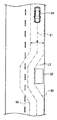
- first obstacle On a one-lane road on one side, an obstacle (hereinafter sometimes referred to as “first obstacle”) 61 exists in front of the own vehicle 60 in the first lane L1 (own lane) in which the own vehicle 60 travels.
- the oncoming vehicle 64 is traveling in the second lane L2 which is the adjacent lane (oncoming lane) adjacent to the first lane L1 and is approaching the host vehicle 60.
- the alternate long and short dash line 65 indicates an expected trajectory that the right end of the oncoming vehicle 64 can pass through
- the alternate long and short dash line 66 indicates an expected trajectory that the left end of the oncoming vehicle 64 can pass through.
- the region sandwiched between the predicted track 65 and the predicted track 66 is a region through which the entire vehicle body of the traveling oncoming vehicle 64 can pass, and is hereinafter referred to as a “traveling region”.
- the own vehicle 60 cannot cross the lane boundary line (center line) and avoid the first obstacle 61, and therefore, the vehicle stops and the own vehicle 60 stops. It is necessary to wait until the passing between the vehicle 60 and the oncoming vehicle 64 is completed.
- an obstacle in the traveling direction of the first lane L1 in front of the first obstacle 61 in the traveling direction of the host vehicle in the second lane L2 (downward in FIGS. 2A and 2B) ( If there is a “second obstacle” 62), the own vehicle 60 stopped at the position 63 before the first obstacle 61 runs the oncoming vehicle 64 avoiding the second obstacle 62. May interfere with area. As a result, the traveling of the oncoming vehicle 64 may be hindered.
- the oncoming vehicle 64 is approaching at a position where the own vehicle 60 is on the front side in the traveling direction with respect to the second obstacle 62, and the second obstacle 62 is the first obstacle.
- the stop position of the own vehicle 60 is determined to be a stop position 67 (hereinafter, referred to as “first stop position”) before the second obstacle 62.
- first stop position a stop position 67
- the host vehicle 60 stops at the first stop position 67 before the second obstacle 62
- the host vehicle 60 is prevented from interfering with the traveling of the oncoming vehicle 64 that avoids the second obstacle 62. be able to. That is, it is possible to prevent the own vehicle 60 and the second obstacle 62 on the second lane L2 from interfering with the traveling of the oncoming vehicle 64.
- the controller 40 of the driving support device 1 includes a first obstacle detection unit 80, an oncoming vehicle detection unit 81, a second obstacle detection unit 82, an oncoming vehicle traveling trajectory estimation unit 83, an interference determination unit 84, and a stop.
- the position determination unit 85 and the trajectory generation unit 86 are provided.
- the functions of the first obstacle detection unit 80, the oncoming vehicle detection unit 81, the second obstacle detection unit 82, the oncoming vehicle traveling trajectory estimation unit 83, the interference determination unit 84, the stop position determination unit 85, and the trajectory generation unit 86 are:
- the processor 41 of the controller 40 may be realized by executing a computer program stored in the storage device 42.
- the first obstacle detection unit 80 receives the surrounding environment information output from the surrounding sensor group 10.
- the first obstacle detection unit 80 detects (identifies) the first obstacle 61 existing on the first lane L1 in which the vehicle 60 is traveling and in front of the route of the vehicle 60 from the surrounding environment information, and Information such as the position of the first obstacle 61 is acquired as the first obstacle information.
- the communication unit 27 of the navigation system 20 may receive information such as the position of the first obstacle 61 detected by another vehicle through vehicle-to-vehicle communication or road-to-vehicle communication.
- the first obstacle detection unit 80 may acquire the information received by the communication unit 27 as the first obstacle information.
- the “obstacle” is an avoidance target that the vehicle 60 should avoid, and is, for example, a vehicle such as a passenger car, a large truck, a two-wheeled vehicle, parked, stopped, decelerating, or a stationary object other than the vehicle, Alternatively, it includes a moving body that is slower than the prescribed vehicle speed on the road.
- Stationary objects other than vehicles include temporary objects and fallen objects such as construction sites on roads.
- Slow moving vehicles include bicycles, pedestrians, and animals.
- the first obstacle detection unit 80 outputs the first obstacle information to the oncoming vehicle traveling trajectory estimation unit 83, the interference determination unit 84, and the stop position determination unit 85.
- the oncoming vehicle detection unit 81 receives the surrounding environment information output from the surrounding sensor group 10. From the surrounding environment information, the first obstacle detection unit 80 detects (identifies) the oncoming vehicle 64 that is traveling in the second lane L2, which is the oncoming lane adjacent to the first lane L1, and is approaching the host vehicle 60. Information such as the position of the vehicle 64 is acquired as oncoming vehicle information. The oncoming vehicle detection unit 81 also determines the size of the oncoming vehicle 64 (the length in the front-rear direction and the length in the front-rear direction) based on the point cloud data of the oncoming vehicle 64 measured by the distance measuring device 11 and the image of the oncoming vehicle 64 taken by the camera 12. The vehicle width) and the attitude (for example, the yaw angle) may be detected (specified), and the size and attitude information of the oncoming vehicle 64 may be acquired as the oncoming vehicle information.
- the oncoming vehicle detection unit 81 may acquire the vehicle type information of the oncoming vehicle 64 as the oncoming vehicle information based on the image of the oncoming vehicle 64 captured by the camera 12.
- the oncoming vehicle detection unit 81 may specify the vehicle type of the oncoming vehicle 64 by pattern matching between images of various vehicles stored in advance in the storage device 42 of the controller 40 and the images of the oncoming vehicle 64 captured by the camera 12. ..
- the oncoming vehicle detection unit 81 transmits the image of the oncoming vehicle 64 captured by the camera 12 to an external device (for example, a server device) via the communication unit 27, and the external device is based on the image of the oncoming vehicle 64.
- the communication unit 27 may receive the information on the vehicle type of the oncoming vehicle 64 specified by the above.
- the oncoming vehicle detection unit 81 may acquire the size information of the oncoming vehicle 64 as the oncoming vehicle information based on the vehicle type of the oncoming vehicle 64.
- the storage device 42 or the like of the controller 40 may store a database in which vehicle types of various vehicles are associated with size information.
- the oncoming vehicle detection unit 81 may specify the size of the oncoming vehicle 64 based on the database and the vehicle type of the oncoming vehicle 64. Further, for example, the oncoming vehicle detection unit 81 transmits the information on the vehicle type of the oncoming vehicle 64 to the external device (for example, the server device or the like) via the communication unit 27, and the external device specifies based on the vehicle type of the oncoming vehicle 64.
- the communication unit 27 may receive information on the size of the oncoming vehicle 64.
- the oncoming vehicle detection unit 81 may acquire information on the driving skill level of the oncoming vehicle 64 as the oncoming vehicle information.
- the oncoming vehicle detection unit 81 may receive from the oncoming vehicle 64 by vehicle-to-vehicle communication or road-to-vehicle communication.
- the oncoming vehicle 64 may include a controller that calculates the driving skill level of the oncoming vehicle 64 based on the driving history of the driver of the oncoming vehicle 64.
- the driving skill level may be calculated based on the driving history of the driver's steering operation speed, accelerator operation speed, brake operation speed, inter-vehicle distance, and the like.
- the oncoming vehicle detection unit 81 determines whether or not the oncoming vehicle 64 is an autonomous driving vehicle based on the vehicle type of the oncoming vehicle 64, and provides information on the driving skill level and control content of the oncoming vehicle 64 in the automatic driving. , May be acquired as information on the driving skill level of the oncoming vehicle 64.
- the storage device 42 or the like of the controller 40 may store a database in which vehicle types of various vehicles are associated with information regarding an automatic driving function.
- the oncoming vehicle detection unit 81 determines whether or not the oncoming vehicle 64 is an autonomous driving vehicle based on the database and the vehicle type of the oncoming vehicle 64, and obtains information on the driving skill level and control content of the oncoming vehicle 64 in the automatic driving. May be specified.
- the oncoming vehicle detection unit 81 transmits information on the vehicle type of the oncoming vehicle 64 to an external device (for example, a server device or the like) via the communication unit 27, and the external device specifies based on the vehicle type of the oncoming vehicle 64.
- the communication unit 27 may receive information on the driving skill level of automatic driving and control contents.
- the communication unit 27 may receive information on the position, size, posture, and vehicle type of the oncoming vehicle 64 from another vehicle such as the oncoming vehicle 64 through vehicle-to-vehicle communication or road-to-vehicle communication.
- the oncoming vehicle detection unit 81 may acquire the information received by the communication unit 27 as the oncoming vehicle information.
- the oncoming vehicle detection unit 81 outputs the oncoming vehicle information to the oncoming vehicle traveling trajectory estimation unit 83 and the stop position determination unit 85.
- the second obstacle detection unit 82 receives the surrounding environment information output from the surrounding sensor group 10.
- the second obstacle detection unit 82 detects (identifies) the second obstacle 62 existing on the second lane L2, which is the oncoming lane, and ahead of the route of the host vehicle 60 from the surrounding environment information, and the second obstacle is detected.
- Information such as the position of the object 62 is acquired as the second obstacle information.
- the communication unit 27 of the navigation system 20 may receive information such as the position of the second obstacle 62 detected by another vehicle through vehicle-to-vehicle communication or road-to-vehicle communication.
- the second obstacle detection unit 82 may acquire the information received by the communication unit 27 as the second obstacle information.
- the second obstacle detection unit 82 outputs the second obstacle information to the oncoming vehicle traveling trajectory estimation unit 83 and the stop position determination unit 85.
- the oncoming vehicle traveling trajectory estimation unit 83 determines that the second obstacle 62 in the second lane L2 is a vehicle other than the first obstacle 61 in the first lane L1 based on the first obstacle information and the second obstacle information. It is determined whether the value is close to 60. That is, the oncoming vehicle traveling trajectory estimation unit 83 determines that the front-rear distance between the second obstacle 62 and the host vehicle 60 (that is, the traveling direction distance) is greater than the front-rear distance between the first obstacle 61 and the host vehicle 60. Also determines if it is too short. The oncoming vehicle traveling trajectory estimation unit 83 outputs the determination result of whether or not the second obstacle 62 is closer to the host vehicle 60 than the first obstacle 61 to the stop position determination unit 85.
- the oncoming vehicle running trajectory estimation unit 83 estimates a predicted running trajectory where the oncoming vehicle 64 is predicted to run in the future. For example, the oncoming vehicle traveling trajectory estimation unit 83 predicts the traveling of the oncoming vehicle 64 based on the surrounding environment information output from the surrounding sensor group 10, the first obstacle information, the second obstacle information, and the oncoming vehicle information. The trajectory may be estimated. For example, in the driving scenes shown in FIGS. 2A and 2B, the oncoming vehicle running trajectory estimation unit 83 estimates the predicted running trajectory of the oncoming vehicle 64 that avoids the second obstacle 62 in the second lane L2.
- the oncoming vehicle traveling trajectory estimation unit 83 may detect the lane boundary of the second lane L2 from the surrounding environment information.
- the oncoming vehicle traveling trajectory estimation unit 83 determines the position of the lane boundary of the second lane L2, the movement history of the oncoming vehicle 64, the history of the posture of the oncoming vehicle 64, the vehicle speed of the oncoming vehicle 64, the oncoming vehicle 64 and the first obstacle 61.
- the predicted traveling trajectory of the oncoming vehicle 64 may be estimated based on the relative positional relationship between the oncoming vehicle 64 and the second obstacle 62, and the like.
- the alternate long and short dash line 91 indicates the predicted traveling path of the oncoming vehicle 64.
- the oncoming vehicle traveling trajectory estimation unit 83 is based on the predicted traveling trajectory 91 of the oncoming vehicle 64, and is opposed to the oncoming vehicle sandwiched between an expected trajectory 65 that the right end of the oncoming vehicle 64 can pass and an expected trajectory 66 that the left end of the oncoming vehicle 64 can pass.
- the travel area of the vehicle 64 is predicted.
- the oncoming vehicle travel trajectory estimation unit 83 may estimate, as the travel area, a region that extends along the predicted travel trajectory 91 and has a width W centered on the predicted travel trajectory 91.
- the oncoming vehicle traveling trajectory estimation unit 83 may set the width W to be a length obtained by adding a predetermined margin to the vehicle width detected by the oncoming vehicle detection unit 81.
- the oncoming vehicle running trajectory estimation unit 83 may change the margin of the running area of the oncoming vehicle 64 according to the driving skill level of the oncoming vehicle 64 acquired by the oncoming vehicle detection unit 81. That is, the oncoming vehicle traveling trajectory estimation unit 83 may estimate the traveling area of the oncoming vehicle 64 based on the driving skill level of the oncoming vehicle 64 and the like.
- the width W of the travel area may be increased by increasing the margin of the travel area.
- the oncoming vehicle traveling trajectory estimation unit 83 outputs the estimated traveling area of the oncoming vehicle 64 to the interference determination unit 84.
- the interference determination unit 84 determines that the own vehicle 60 is the oncoming vehicle 64. It is determined whether there is a possibility of interfering with the traveling area of. Please refer to FIG. 2A. For example, the interference determination unit 84 determines, based on the front-rear direction position of the first obstacle 61 indicated by the first obstacle information (that is, the position in the traveling direction of the vehicle 60, which will be also referred to as the traveling direction position below). 1 The vehicle 60 stops before the obstacle 61, and the stop position 63 where the vehicle 60 and the oncoming vehicle 64 pass each other is determined.
- the interference determination unit 84 allows the host vehicle 60 to pass the first obstacle 61 by smooth steering after the host vehicle 60 stopped at the stop position 63 and the oncoming vehicle 64 pass each other.
- the position in the front-rear direction and the position in the lateral direction may be determined.
- the interference determination unit 84 may cause the host vehicle 60 to interfere with the travel area of the oncoming vehicle 64 depending on whether or not the area occupied by the host vehicle 60 and the travel area of the oncoming vehicle 64 overlap. You may decide whether or not. For example, the interference determination unit 84 may determine that the own vehicle 60 may interfere with the traveling area of the oncoming vehicle 64 when the occupied area of the own vehicle 60 stopped at the stop position 63 and the traveling area of the oncoming vehicle 64 overlap. You can judge. For example, the interference determination unit 84 may determine that the own vehicle 60 may not interfere with the traveling area of the oncoming vehicle 64 when the occupied area of the own vehicle 60 and the traveling area of the oncoming vehicle 64 do not overlap. Please refer to FIG. The interference determination unit 84 outputs the determination result of the possibility that the own vehicle 60 interferes with the traveling area of the oncoming vehicle 64 to the stop position determination unit 85.
- the stop position determination unit 85 determines the stop position to wait for the passing of the own vehicle 60 and the oncoming vehicle 64 to be completed based on the determination result of the interference determination unit 84.
- the stop position determination unit 85 causes the second obstacle 62 to stop.
- the first stop position 67 (see FIG. 2B) before this is determined as the stop position of the vehicle 60.
- the stop position determination unit 85 determines the front-rear direction position of the first stop position 67 (that is, the traveling direction position), for example, the front-rear direction distance (that is, the traveling direction distance) between the second obstacle 62 and the host vehicle 60 as the first stop position. It may be determined that the own vehicle 60 stopped at 67 does not interfere with the traveling area of the oncoming vehicle 64 that returns to the second lane L2 while avoiding the second obstacle 62. For example, the stop position determination unit 85 may determine the front-rear direction position of the first stop position 67 before the section in which the traveling area of the oncoming vehicle 64 extends beyond the first lane L1.
- the stop position determination unit 85 causes the first obstacle 61 indicated by the first obstacle information.
- the stop position 90 is determined based on the position in the front-rear direction (that is, the position in the traveling direction).
- the host vehicle 60 waits for completion of the passing of the host vehicle 60 and the oncoming vehicle 64 at the stop position 90.
- the stop position determination unit 85 may set the stop position 90 to a position in front of the first obstacle 61 by a predetermined distance such that the vehicle 60 can avoid the first obstacle 61, for example.
- the stop position determination unit 85 causes the first obstacle.
- the stop position 90 is determined based on the front-rear direction position (that is, the traveling direction position) of the first obstacle 61 indicated by the information.
- the interference determination unit 84 after the vehicle 60 stopped at the stop position 90 and the oncoming vehicle 64 pass each other,
- the front-rear direction position and the lateral position (that is, the vehicle width direction position) of the stop position 90 may be determined so that the host vehicle 60 can pass (avoid) the first obstacle 61 by smooth steering.
- the front-rear direction position and the lateral position of the stop position 90 are predetermined with respect to the first obstacle 61, with a sufficient distance for the vehicle 60 to avoid the first obstacle 61.
- the position may be the position, or the position may be set based on the calculated traveling region by calculating the traveling region when the host vehicle 60 avoids the first obstacle 61 by smooth steering.
- the stop position determination unit 85 outputs information on the determined stop position of the own vehicle 60 to the track generation unit 86.
- the trajectory generation unit 86 determines whether or not the host vehicle is based on the surrounding environment information output from the surrounding sensor group 10, the road map data and the traveling route output from the navigation system 20, the vehicle information output from the vehicle sensor group 30, and the like. Generate a running track for running.
- the track generation unit 86 reaches the stop position determined by the stop position determination unit 85 in order to stop the own vehicle 60 before avoiding the first obstacle 61 and wait for completion of passing by the oncoming vehicle 64. Generate the running trajectory of.
- the trajectory generation unit 86 includes a speed profile for stopping the own vehicle at the stop position or decelerating the stop position and passing the stop position based on the vehicle information output from the vehicle sensor group 30. A traveling track may be generated.
- the trajectory generation unit 86 outputs the generated traveling trajectory to the traveling control device 50.
- the traveling control device 50 causes the own vehicle 60 to travel to the stop position determined by the stop position determination unit 85 based on the travel trajectory generated by the trajectory generation unit 86, and places the own vehicle 60 in the stop position to provide driving assistance. To do. For example, when the second obstacle 62 is present on the front side of the first obstacle 61 in the traveling direction of the own vehicle 60 and the own vehicle 60 is stopped before the first obstacle 61, the own vehicle 60 is an oncoming vehicle. 2B, the host vehicle 60 travels to the first stop position 67 in front of the second obstacle 62 in the traveling direction of the host vehicle 60 as shown in FIG. 2B. The vehicle 60 is stopped at the first stop position 67.
- the host vehicle 60 waits before the second obstacle 62, it is possible to prevent the traveling of the oncoming vehicle 64 that avoids the second obstacle 62 from being obstructed.
- the first obstacle 61 is set on the basis of the position of the first obstacle 61 as shown in FIG. 5A. Even when the host vehicle 60 stops at the stop position 90 determined to be on the front side in the traveling direction of the host vehicle 60 from the obstacle 61, the traveling of the oncoming vehicle 64 that avoids the second obstacle 62 is not hindered.
- the traveling control device 50 causes the host vehicle 60 to travel to the stop position 90 determined based on the front-rear direction position (that is, the traveling direction position) of the first obstacle 61, and sets the host vehicle 60 to the stop position 90. Stop.
- step S1 the first obstacle detection unit 80 determines whether or not the first obstacle 61 exists ahead of the route of the host vehicle 60 in the first lane L1.
- step S1:Y the process proceeds to step S3. If the first obstacle 61 does not exist (step S1:N), the process proceeds to step S2.
- step S2 the track generation unit 86 generates a running track that goes straight in the first lane L1. After that, the process proceeds to step S12.
- step S3 the oncoming vehicle detection unit 81 determines whether or not there is an oncoming vehicle 64 that travels in the second lane L2, which is the oncoming lane, and approaches the own vehicle 60.
- step S5 the process proceeds to step S5.
- step S4 the process proceeds to step S4.
- step S4 the trajectory generation unit 86 generates a traveling trajectory that avoids the first obstacle 61 in the first lane L1 and travels. After that, the process proceeds to step S12.
- step S5 the second obstacle detection unit 82 determines whether or not the second obstacle 62 exists ahead of the route of the host vehicle 60 in the second lane L2. When the second obstacle 62 exists (step S5: Y), the process proceeds to step S6. If the second obstacle 62 does not exist (step S5: N), the process proceeds to step S10.
- step S6 the oncoming vehicle traveling trajectory estimation unit 83 positions the second obstacle 62 in the second lane L2 on the front side in the traveling direction of the host vehicle 60 with respect to the position of the first obstacle 61 in the first lane L1. Determine whether or not.
- step S6: Y the position of the second obstacle 62 is on the front side of the position of the first obstacle 61 in the traveling direction of the host vehicle 60
- step S7 the process proceeds to step S10.
- step S7 the oncoming vehicle traveling trajectory estimation unit 83 estimates the predicted traveling trajectory 91 of the oncoming vehicle 64 traveling while avoiding the second obstacle 62, and avoids the second obstacle 62 based on the predicted traveling trajectory 91. Then, the traveling area of the oncoming vehicle 64 traveling is estimated.
- step S8 the interference determination unit 84 determines whether or not the own vehicle 60 may interfere with the traveling area of the oncoming vehicle 64 when the own vehicle 60 is stopped in front of the first obstacle 61.
- step S8:Y If the host vehicle 60 may interfere with the traveling area of the oncoming vehicle 64 (step S8:Y), the process proceeds to step S9.
- step S9 the stop position determination unit 85 determines the front-rear direction position (that is, the traveling direction position) of the first stop position 67 at which the vehicle 60 is stopped, based on the position of the second obstacle 62 in the second lane L2. ..
- the stop position determination unit 85 determines the front-rear direction position of the first stop position 67 in front of the second obstacle 62. After that, the process proceeds to step S11.
- step S10 the stop position determination unit 85 determines the front-rear direction position (that is, the traveling direction position) of the stop position 90 at which the host vehicle 60 is stopped, with the position of the first obstacle 61 in the first lane L1 as a reference. After that, the process proceeds to step S11.
- step S11 the trajectory generation unit 86 generates a traveling trajectory for reaching the stop position determined by the stop position determination unit 85.
- step S12 the traveling control device 50 causes the own vehicle 60 to travel to the stop position determined by the stop position determination unit 85 based on the travel trajectory generated by the trajectory generation unit 86, and stops the own vehicle 60 at the stop position. Provide driving assistance. After that, the process ends.
- the traveling control device 50 stops the vehicle 60 at the stop position determined by the stop position determination unit 85 is described, but the invention is not limited to this.
- the vehicle stop position may be presented to the driver of the vehicle 60 by displaying the vehicle stop position determined by the vehicle stop position determination unit 85 on the navigation screen, etc., to assist the vehicle stop of the vehicle 60 at the vehicle stop position.
- the first obstacle detection unit 80 detects the position of the first obstacle 61 ahead of the host vehicle 60 in the traveling direction in the first lane L1 in which the host vehicle 60 travels.
- the second obstacle detection unit 82 detects the position of the second obstacle 62 ahead of the host vehicle 60 in the traveling direction in the second lane L2, which is the opposite lane adjacent to the first lane L1.
- the stop position determination unit 85 sets the stop position of the host vehicle 60 to the second obstacle 62.
- the first stop position 67 before this is determined, and the stop of the own vehicle 60 to the first stop position 67 is supported.
- the stop position determination unit 85 may determine the stop position of the host vehicle 60 to be the first stop position 67 when there is a possibility of interfering with the traveling area of the oncoming vehicle 64. As a result, the stop position of the host vehicle 60 can be switched based on whether or not the traveling of the oncoming vehicle 64 is disturbed. It is possible to wait for the vehicle 60 and the oncoming vehicle 64 to pass each other.
- the oncoming vehicle traveling trajectory estimation unit 83 may estimate the traveling area of the oncoming vehicle 64.
- the interference determination unit 84 determines whether the vehicle 60 travels in the oncoming vehicle 64 depending on whether the estimated traveling area and the area occupied by the vehicle 60 when the vehicle stops before the first obstacle 61 overlap. May interfere with the. As a result, it can be determined whether or not the stopped vehicle 60 may interfere with the traveling area of the oncoming vehicle 64.
- the oncoming vehicle detection unit 81 may determine the driving skill level of the oncoming vehicle 64.
- the oncoming vehicle running trajectory estimation unit 83 may estimate the running area of the oncoming vehicle 64 according to the driving skill level. As a result, even if the oncoming vehicle 64 has a low driving skill level, the host vehicle 60 can be put on standby at a safe position.
- the stop position determination unit 85 uses the front-rear direction position (that is, the traveling direction position) of the first obstacle 61 as a reference.
- the stop position of the vehicle 60 may be determined.
- the oncoming vehicle 64 that avoids the second obstacle 62 even if the vehicle stops at an arbitrary position before the first obstacle 61. Does not interfere with the own vehicle 60. Therefore, in this case, the first obstacle 61 can be avoided more quickly by advancing the host vehicle 60 to a position closer to the first obstacle 61 before passing the oncoming vehicle 64.
- the configuration of the driving support device 1 according to the second embodiment is basically the same as the configuration of the driving support device 1 according to the first embodiment shown in FIG.
- the functional configuration of the controller 40 according to the second embodiment is basically the same as the functional configuration of the controller 40 shown in FIG. Please refer to FIG.
- the oncoming vehicle in which the host vehicle 60 stopped at the first stop position 67 avoids the second obstacle 62 and returns to the second lane L2 as in the first embodiment.
- the first stop position 67 is determined so as not to interfere with the travel area of 64.
- the driving support device 1 determines the size of the oncoming vehicle 64.
- the driving assistance apparatus 1 may determine the size of the oncoming vehicle 64, for example, the length L in the front-rear direction of the oncoming vehicle 64, or may determine the vehicle width of the oncoming vehicle 64.
- the first stop position is corrected to the position 92 on the front side in the traveling direction of the host vehicle 60 from the second obstacle 62. That is, when the size of the oncoming vehicle 64 exceeds the threshold value, the first stop position is corrected to the front side in the traveling direction of the vehicle 60 from the second obstacle 62.
- the second obstacle 62 is located closer to the front side in the traveling direction of the host vehicle 60.
- the oncoming vehicle 64 is separated from the position where the oncoming vehicle 64 protrudes into the first lane L1 (or the position near the first lane L1) in order to avoid the second obstacle 62. It is possible to wait for the completion of the passing between the vehicle 60 and the vehicle 60. As a result, for example, the fear that an occupant feels when passing by a large oncoming vehicle 64 such as a truck or a large trailer can be reduced.
- the stop position determination unit 85 illustrated in FIG. 3 is configured such that the vehicle 60 that has stopped at the first stop position 67 from the front-rear direction position of the first stop position 67 (that is, the traveling direction position) has the second obstacle. It is determined so as not to interfere with the traveling area of the oncoming vehicle 64 that avoids 62 and returns to the second lane L2. Next, the stop position determination unit 85 determines whether or not the size of the oncoming vehicle 64 exceeds a predetermined threshold value based on the oncoming vehicle information output by the oncoming vehicle detection unit 81.
- the stop position determining unit 85 determines the first stop position from the second obstacle 62 as compared with the case where the size of the oncoming vehicle 64 does not exceed the threshold value. It is corrected to a position 92 closer to the front in the traveling direction of the vehicle 60.
- steps S21 to S29 is the same as the processing of steps S1 to S9 described with reference to FIG.
- the processing of steps S32 to S34 is the same as the processing of steps S10 to S12 described with reference to FIG.
- the stop position determination unit 85 determines the front-rear direction position of the first stop position 67 based on the position of the second obstacle 62 in step S29, the process proceeds to step S30.
- step S30 the stop position determination unit 85 determines whether or not the size of the oncoming vehicle 64 is equal to or smaller than the threshold value.
- step S30: Y the process proceeds to step S33.
- the first stop position 67 determined in step S29 is determined as the stop position of the vehicle 60 without correction.
- step S30: N the process proceeds to step S31.
- step S31 the stop position determination unit 85 shifts the first stop position 67 determined in step S29 rearward. That is, the stop position determination unit 85 corrects the first stop position to the position 92 farther from the second obstacle 62. After that, the process proceeds to step S33.
- the oncoming vehicle detection unit 81 determines the size of the oncoming vehicle 64.
- the stop position determination unit 85 sets the first stop position from the second obstacle 62 to the own vehicle 60 as compared with the case where the size of the oncoming vehicle 64 does not exceed the threshold value. Set to a position closer to you in the direction of travel. In this way, by setting the first stop position at a position closer to the front side in the traveling direction of the host vehicle 60 from the second obstacle 62, the oncoming vehicle 64 toward the first lane L1 in order to avoid the second obstacle 62.
- the configuration of the driving support device 1 according to the third embodiment is basically the same as the configuration of the driving support device 1 according to the first embodiment shown in FIG.
- the functional configuration of the controller 40 according to the third embodiment is basically the same as the functional configuration of the controller 40 shown in FIG. Please refer to FIG.
- the interference determination unit 84 of the controller 40 according to the third embodiment places the host vehicle at a stop position (hereinafter referred to as “second stop position”) 93 in front of the first obstacle 61 in the traveling direction of the host vehicle 60.
- the second stop position 93 may be determined similarly to the stop position 90 described with reference to FIGS. 5A and 5B, for example.
- the stop position determination unit 85 moves the second stop position 93 laterally away from the second lane L2.
- a stop position (hereinafter, referred to as a “third stop position”) 94 that has moved in a direction (lane width direction) away from the oncoming lane 64 is determined. That is, when the vehicle is required to pass on the left side, the second stop position 93 is moved to the left to determine the third stop position 94. If the vehicle is required to pass on the right side, the second stop position 93 is moved to the right to define the third stop position 94.
- the stop position determination unit 85 determines whether the host vehicle 60 stopped at the third stop position 94 interferes with the traveling area of the oncoming vehicle 64. When the host vehicle 60 stopped at the third stop position 94 does not interfere with the traveling area of the oncoming vehicle 64, the stop position determination unit 85 determines the stop position of the host vehicle 60 as the third stop position 94. The host vehicle 60 stops at the third stop position 94 before avoiding the first obstacle 61, and waits for the completion of passing the oncoming vehicle 64.
- steps S41 to S47 is the same as the processing of steps S1 to S7 described with reference to FIG.
- the processing of steps S51 to S54 is the same as the processing of steps S9 to S12 described with reference to FIG.
- the interference determination unit 84 uses the front-rear direction position (that is, the traveling direction position) of the first obstacle 61 as a reference.
- the second stop position 93 is determined in front of the first obstacle 61.
- the interference determination unit 84 determines whether or not the own vehicle 60 may interfere with the traveling area of the oncoming vehicle 64 when the own vehicle 60 stops at the second stop position 93.
- the process proceeds to step S49.
- the host vehicle 60 stopped at the second stop position 93 does not interfere with the traveling area of the oncoming vehicle 64 (step S48: N)
- the process proceeds to step S52.
- step S49 the stop position determination unit 85 laterally moves the second stop position 93 away from the second lane L2 in the lane width direction to determine the third stop position 94.
- the stop position determination unit 85 determines whether the host vehicle 60 stopped at the third stop position 94 interferes with the traveling area of the oncoming vehicle 64.
- step S49: Y the process proceeds to step S51.
- the stop position determination unit 85 determines the front-rear direction position of the first stop position 67 based on the position of the second obstacle 62.
- step S50 the stop position determination unit 85 determines the third stop position 94, which is determined by laterally shifting the second stop position 93 so as to move away from the second lane L2, as the stop position of the host vehicle 60. After that, the process proceeds to step S53.
- the stop position determination unit 85 makes the second stop so as to move away from the second lane L2 in the lane width direction. The position 93 is moved laterally to determine the third stop position 94.
- the stop position determination unit 85 determines the stop position of the host vehicle 60 as the third stop position 94.
- the host vehicle 60 can be stopped at a position that does not interfere with the traveling of the oncoming vehicle 64, and the host vehicle 60 can be advanced to a position closer to the first obstacle 61 before passing the oncoming vehicle 64, so that the host vehicle 60 can be moved more quickly.
- the first obstacle 61 can be avoided.
- SYMBOLS 1... Driving support device 2... Running track generation device, 10... Surrounding sensor group, 11... Distance measuring device, 12... Camera, 20... Navigation system, 21... Navigation controller, 22... Positioning device, 23... Map database, 24 Display unit 25 Operation unit 26 Voice output unit 27 Communication unit 30 Vehicle sensor group 31 Vehicle speed sensor 32 Acceleration sensor 33 Gyro sensor 34 Steering angle sensor 35 Accelerator Sensor, 36... Brake sensor, 40... Controller, 41... Processor, 42... Storage device, 50... Travel control device, 51... Actuator group, 52... Steering actuator, 53... Accelerator opening actuator, 54... Brake control actuator, 60 ... Own vehicle, first lane... L1, 61... First obstacle, L2... Oncoming lane, 62...
- Second obstacle 64... Oncoming vehicle, 80... First obstacle detecting section, 81... Oncoming vehicle detecting section, 82... 2nd obstacle detection part, 83... Oncoming vehicle running track estimation part, 84... Interference determination part, 85... Stop position determination part, 86... Track generation part
Abstract
Dans le procédé d'aide à la conduite selon l'invention, la position d'un premier obstacle (61) devant un véhicule (60) dans une première voie (L1) dans laquelle le véhicule se déplace est détectée (S1), la position d'un second obstacle (62) devant le véhicule dans une seconde voie (L2) qui est une voie venant en sens inverse adjacente à la première voie est détectée (S5), une première position d'arrêt (67) est déterminée (S6, S9) en tant que position d'arrêt pour le véhicule dans une position devant le second obstacle dans la direction de déplacement du véhicule lorsque la position du second obstacle est plus avancée que la position du premier obstacle dans la direction de déplacement du véhicule, et une aide est apportée (S11, S12) pour l'arrêt du véhicule à la première position d'arrêt déterminée.
Priority Applications (5)
| Application Number | Priority Date | Filing Date | Title |
|---|---|---|---|
| CN201980089138.4A CN113302105A (zh) | 2019-01-15 | 2019-01-15 | 驾驶辅助方法及驾驶辅助装置 |
| PCT/IB2019/000052 WO2020148561A1 (fr) | 2019-01-15 | 2019-01-15 | Procédé d'aide à la conduite et dispositif d'aide à la conduite |
| US17/422,595 US20210387615A1 (en) | 2019-01-15 | 2019-01-15 | Driving Assistance Method and Driving Assistance Device |
| EP19909634.8A EP3912877B1 (fr) | 2019-01-15 | 2019-01-15 | Procédé d'aide à la conduite et dispositif d'aide à la conduite |
| JP2020566341A JP7377822B2 (ja) | 2019-01-15 | 2019-01-15 | 運転支援方法及び運転支援装置 |
Applications Claiming Priority (1)
| Application Number | Priority Date | Filing Date | Title |
|---|---|---|---|
| PCT/IB2019/000052 WO2020148561A1 (fr) | 2019-01-15 | 2019-01-15 | Procédé d'aide à la conduite et dispositif d'aide à la conduite |
Publications (1)
| Publication Number | Publication Date |
|---|---|
| WO2020148561A1 true WO2020148561A1 (fr) | 2020-07-23 |
Family
ID=71614441
Family Applications (1)
| Application Number | Title | Priority Date | Filing Date |
|---|---|---|---|
| PCT/IB2019/000052 WO2020148561A1 (fr) | 2019-01-15 | 2019-01-15 | Procédé d'aide à la conduite et dispositif d'aide à la conduite |
Country Status (5)
| Country | Link |
|---|---|
| US (1) | US20210387615A1 (fr) |
| EP (1) | EP3912877B1 (fr) |
| JP (1) | JP7377822B2 (fr) |
| CN (1) | CN113302105A (fr) |
| WO (1) | WO2020148561A1 (fr) |
Cited By (1)
| Publication number | Priority date | Publication date | Assignee | Title |
|---|---|---|---|---|
| US11136026B2 (en) * | 2019-03-07 | 2021-10-05 | Honda Motor Co., Ltd. | Vehicle control device |
Families Citing this family (2)
| Publication number | Priority date | Publication date | Assignee | Title |
|---|---|---|---|---|
| JP7243227B2 (ja) * | 2019-01-29 | 2023-03-22 | トヨタ自動車株式会社 | 車両制御装置 |
| JP2022037448A (ja) * | 2020-08-25 | 2022-03-09 | スズキ株式会社 | 運転支援装置 |
Citations (4)
| Publication number | Priority date | Publication date | Assignee | Title |
|---|---|---|---|---|
| JP2008174023A (ja) * | 2007-01-16 | 2008-07-31 | Denso Corp | すれ違い自動走行制御装置及び運転支援システム |
| JP2008217079A (ja) * | 2007-02-28 | 2008-09-18 | Denso Corp | 運転支援システム |
| JP2013184563A (ja) * | 2012-03-07 | 2013-09-19 | Hitachi Automotive Systems Ltd | 車両走行制御装置 |
| JP2016143137A (ja) * | 2015-01-30 | 2016-08-08 | 富士重工業株式会社 | 車両の運転支援装置 |
Family Cites Families (25)
| Publication number | Priority date | Publication date | Assignee | Title |
|---|---|---|---|---|
| JP3358709B2 (ja) * | 1997-08-11 | 2002-12-24 | 富士重工業株式会社 | 車両用運転支援装置 |
| DE10332961A1 (de) * | 2003-07-21 | 2005-02-17 | Robert Bosch Gmbh | Verfahren und Vorrichtung zur Bestimmung der Position und/oder der zu erwartenden Position eines Fahrzeuges während eines Einpark-Vorgangs in Relation zur Gegenfahrspur einer mehrspurigen Fahrbahn |
| JP4730406B2 (ja) * | 2008-07-11 | 2011-07-20 | トヨタ自動車株式会社 | 走行支援制御装置 |
| JP5407952B2 (ja) * | 2009-06-18 | 2014-02-05 | 日産自動車株式会社 | 車両運転支援装置及び車両運転支援方法 |
| JP2011098614A (ja) * | 2009-11-05 | 2011-05-19 | Aisin Aw Co Ltd | 運転支援装置、運転支援方法、及び運転支援プログラム |
| US9324235B2 (en) * | 2011-12-27 | 2016-04-26 | Honda Motor Co., Ltd. | Driving assistance system |
| DE102012215093A1 (de) * | 2012-08-24 | 2014-02-27 | Robert Bosch Gmbh | Fahrerassistenzsystem und Verfahren zum Betreiben des Fahrerassistenzsystems |
| US9669826B2 (en) * | 2012-11-21 | 2017-06-06 | Toyota Jidosha Kabushiki Kaisha | Driving-assistance device and driving-assistance method |
| JP6304011B2 (ja) * | 2014-12-11 | 2018-04-04 | トヨタ自動車株式会社 | 車両用走行制御装置 |
| DE102015201272A1 (de) * | 2015-01-26 | 2016-07-28 | Robert Bosch Gmbh | Verfahren zum Betreiben einer Regelungsvorrichtung eines Kraftfahrzeugs |
| JP6545507B2 (ja) * | 2015-03-31 | 2019-07-17 | アイシン・エィ・ダブリュ株式会社 | 自動運転支援システム、自動運転支援方法及びコンピュータプログラム |
| DE102015210357B4 (de) * | 2015-06-05 | 2021-10-21 | Robert Bosch Gmbh | Verfahren und Vorrichtung zur Unterstützung eines Fahrers eines Kraftfahrzeugs |
| JP6327719B2 (ja) * | 2016-02-04 | 2018-05-23 | 株式会社Subaru | 車両の走行制御装置 |
| DE102016203086B4 (de) * | 2016-02-26 | 2018-06-28 | Robert Bosch Gmbh | Verfahren und Vorrichtung zur Fahrerassistenz |
| CN107521494A (zh) * | 2016-06-22 | 2017-12-29 | 奥迪股份公司 | 超车辅助方法和装置 |
| KR101834351B1 (ko) * | 2016-07-14 | 2018-03-05 | 엘지전자 주식회사 | 차량용 운전 보조 장치 |
| DE102016221905A1 (de) * | 2016-11-08 | 2018-05-09 | Bayerische Motoren Werke Aktiengesellschaft | Engstellenassistenzsystem und Assistenzverfahren in einem Kraftfahrzeug |
| KR101973627B1 (ko) * | 2017-07-11 | 2019-04-29 | 엘지전자 주식회사 | 차량에 구비된 차량 제어 장치 및 차량의 제어방법 |
| JP7103359B2 (ja) * | 2017-08-04 | 2022-07-20 | ソニーグループ株式会社 | 制御装置、および制御方法、プログラム、並びに移動体 |
| JP6600889B2 (ja) * | 2017-12-13 | 2019-11-06 | 本田技研工業株式会社 | 車両制御装置、車両制御方法、およびプログラム |
| CN108099783A (zh) * | 2017-12-22 | 2018-06-01 | 戴姆勒股份公司 | 一种用于车辆的驾驶辅助系统及其操作方法 |
| JP7132713B2 (ja) * | 2017-12-28 | 2022-09-07 | 株式会社Soken | 車両走行制御装置、車両走行制御システムおよび車両走行制御方法 |
| US11636375B2 (en) * | 2018-02-27 | 2023-04-25 | Toyota Research Institute, Inc. | Adversarial learning of driving behavior |
| GB2572448B (en) * | 2018-03-30 | 2021-02-03 | Jaguar Land Rover Ltd | Vehicle control method and apparatus |
| US11299149B2 (en) * | 2018-07-23 | 2022-04-12 | Denso International America, Inc. | Considerate driving system |
-
2019
- 2019-01-15 WO PCT/IB2019/000052 patent/WO2020148561A1/fr unknown
- 2019-01-15 EP EP19909634.8A patent/EP3912877B1/fr active Active
- 2019-01-15 CN CN201980089138.4A patent/CN113302105A/zh active Pending
- 2019-01-15 US US17/422,595 patent/US20210387615A1/en active Pending
- 2019-01-15 JP JP2020566341A patent/JP7377822B2/ja active Active
Patent Citations (4)
| Publication number | Priority date | Publication date | Assignee | Title |
|---|---|---|---|---|
| JP2008174023A (ja) * | 2007-01-16 | 2008-07-31 | Denso Corp | すれ違い自動走行制御装置及び運転支援システム |
| JP2008217079A (ja) * | 2007-02-28 | 2008-09-18 | Denso Corp | 運転支援システム |
| JP2013184563A (ja) * | 2012-03-07 | 2013-09-19 | Hitachi Automotive Systems Ltd | 車両走行制御装置 |
| JP2016143137A (ja) * | 2015-01-30 | 2016-08-08 | 富士重工業株式会社 | 車両の運転支援装置 |
Cited By (1)
| Publication number | Priority date | Publication date | Assignee | Title |
|---|---|---|---|---|
| US11136026B2 (en) * | 2019-03-07 | 2021-10-05 | Honda Motor Co., Ltd. | Vehicle control device |
Also Published As
| Publication number | Publication date |
|---|---|
| EP3912877A1 (fr) | 2021-11-24 |
| CN113302105A (zh) | 2021-08-24 |
| JP7377822B2 (ja) | 2023-11-10 |
| JPWO2020148561A1 (fr) | 2020-07-23 |
| EP3912877A4 (fr) | 2022-02-09 |
| US20210387615A1 (en) | 2021-12-16 |
| EP3912877B1 (fr) | 2022-12-21 |
Similar Documents
| Publication | Publication Date | Title |
|---|---|---|
| CN111066071B (zh) | 驾驶辅助车辆的位置误差校正方法及位置误差校正装置 | |
| JP6747597B2 (ja) | 運転支援車両の走行制御方法及び走行制御装置 | |
| US20180284798A1 (en) | Vehicle control device | |
| US20210221367A1 (en) | Driving Support Method and Driving Support Device | |
| WO2018066133A1 (fr) | Procédé d'évaluation de véhicule, procédé de correction d'itinéraire de déplacement, dispositif d'évaluation de véhicule et dispositif de correction d'itinéraire de déplacement | |
| WO2020003452A1 (fr) | Procédé d'aide à la conduite et dispositif d'aide à la conduite | |
| JP6436235B2 (ja) | 追従制御装置及び追従制御方法 | |
| WO2020148561A1 (fr) | Procédé d'aide à la conduite et dispositif d'aide à la conduite | |
| US20210061356A1 (en) | Vehicle control device | |
| US20210253108A1 (en) | Vehicle Control Method and Vehicle Control Device | |
| JP7129495B2 (ja) | 運転支援方法及び運転支援装置 | |
| JP7334107B2 (ja) | 車両制御方法及び車両制御装置 | |
| US11231501B2 (en) | Front and side three-LIDAR design for autonomous driving vehicles | |
| JP7336861B2 (ja) | 挙動予測方法及び挙動予測装置 | |
| CN115175838A (zh) | 车辆控制方法及车辆控制装置 | |
| RU2774521C1 (ru) | Способ помощи при вождении и устройство помощи при вождении | |
| JP7038610B2 (ja) | 運転支援方法及び運転支援装置 | |
| JP7458797B2 (ja) | 走行支援方法及び走行支援装置 | |
| US11242057B2 (en) | Method for optimizing three-point turn of autonomous driving vehicles | |
| WO2023047148A1 (fr) | Procédé d'aide au déplacement et dispositif d'aide au déplacement | |
| JP7169892B2 (ja) | 走行支援方法及び走行支援装置 | |
| WO2023032092A1 (fr) | Procédé de commande de véhicule et dispositif de commande de véhicule | |
| WO2024069690A1 (fr) | Procédé d'aide à la conduite et dispositif d'aide à la conduite | |
| US20230065284A1 (en) | Control and planning with localization uncertainty | |
| WO2021074659A1 (fr) | Procédé d'aide à la conduite et dispositif d'aide à la conduite |
Legal Events
| Date | Code | Title | Description |
|---|---|---|---|
| 121 | Ep: the epo has been informed by wipo that ep was designated in this application |
Ref document number: 19909634 Country of ref document: EP Kind code of ref document: A1 |
|
| ENP | Entry into the national phase |
Ref document number: 2020566341 Country of ref document: JP Kind code of ref document: A |
|
| NENP | Non-entry into the national phase |
Ref country code: DE |
|
| ENP | Entry into the national phase |
Ref document number: 2019909634 Country of ref document: EP Effective date: 20210816 |