WO2020148561A1 - 運転支援方法及び運転支援装置 - Google Patents
運転支援方法及び運転支援装置 Download PDFInfo
- Publication number
- WO2020148561A1 WO2020148561A1 PCT/IB2019/000052 IB2019000052W WO2020148561A1 WO 2020148561 A1 WO2020148561 A1 WO 2020148561A1 IB 2019000052 W IB2019000052 W IB 2019000052W WO 2020148561 A1 WO2020148561 A1 WO 2020148561A1
- Authority
- WO
- WIPO (PCT)
- Prior art keywords
- vehicle
- obstacle
- stop position
- traveling
- oncoming
- Prior art date
Links
- 238000000034 method Methods 0.000 title claims abstract description 45
- 230000002452 interceptive effect Effects 0.000 claims description 10
- 238000001514 detection method Methods 0.000 description 41
- 238000004891 communication Methods 0.000 description 32
- 230000008569 process Effects 0.000 description 24
- 238000012545 processing Methods 0.000 description 10
- 230000001133 acceleration Effects 0.000 description 7
- 238000010586 diagram Methods 0.000 description 6
- 239000004065 semiconductor Substances 0.000 description 5
- 230000002093 peripheral effect Effects 0.000 description 4
- 230000000694 effects Effects 0.000 description 3
- 238000005516 engineering process Methods 0.000 description 3
- 230000003287 optical effect Effects 0.000 description 3
- 230000006870 function Effects 0.000 description 2
- 241001465754 Metazoa Species 0.000 description 1
- 206010061876 Obstruction Diseases 0.000 description 1
- 238000013459 approach Methods 0.000 description 1
- 230000006399 behavior Effects 0.000 description 1
- 230000008859 change Effects 0.000 description 1
- 238000004590 computer program Methods 0.000 description 1
- 238000010276 construction Methods 0.000 description 1
- 238000012937 correction Methods 0.000 description 1
- 239000000446 fuel Substances 0.000 description 1
- 230000006872 improvement Effects 0.000 description 1
- 230000010365 information processing Effects 0.000 description 1
- 238000012986 modification Methods 0.000 description 1
- 230000004048 modification Effects 0.000 description 1
- 238000006467 substitution reaction Methods 0.000 description 1
- 230000000007 visual effect Effects 0.000 description 1
Images


Classifications
-
- B—PERFORMING OPERATIONS; TRANSPORTING
- B60—VEHICLES IN GENERAL
- B60W—CONJOINT CONTROL OF VEHICLE SUB-UNITS OF DIFFERENT TYPE OR DIFFERENT FUNCTION; CONTROL SYSTEMS SPECIALLY ADAPTED FOR HYBRID VEHICLES; ROAD VEHICLE DRIVE CONTROL SYSTEMS FOR PURPOSES NOT RELATED TO THE CONTROL OF A PARTICULAR SUB-UNIT
- B60W30/00—Purposes of road vehicle drive control systems not related to the control of a particular sub-unit, e.g. of systems using conjoint control of vehicle sub-units, or advanced driver assistance systems for ensuring comfort, stability and safety or drive control systems for propelling or retarding the vehicle
- B60W30/08—Active safety systems predicting or avoiding probable or impending collision or attempting to minimise its consequences
- B60W30/095—Predicting travel path or likelihood of collision
- B60W30/0956—Predicting travel path or likelihood of collision the prediction being responsive to traffic or environmental parameters
-
- B—PERFORMING OPERATIONS; TRANSPORTING
- B60—VEHICLES IN GENERAL
- B60W—CONJOINT CONTROL OF VEHICLE SUB-UNITS OF DIFFERENT TYPE OR DIFFERENT FUNCTION; CONTROL SYSTEMS SPECIALLY ADAPTED FOR HYBRID VEHICLES; ROAD VEHICLE DRIVE CONTROL SYSTEMS FOR PURPOSES NOT RELATED TO THE CONTROL OF A PARTICULAR SUB-UNIT
- B60W30/00—Purposes of road vehicle drive control systems not related to the control of a particular sub-unit, e.g. of systems using conjoint control of vehicle sub-units, or advanced driver assistance systems for ensuring comfort, stability and safety or drive control systems for propelling or retarding the vehicle
- B60W30/08—Active safety systems predicting or avoiding probable or impending collision or attempting to minimise its consequences
- B60W30/09—Taking automatic action to avoid collision, e.g. braking and steering
-
- B—PERFORMING OPERATIONS; TRANSPORTING
- B60—VEHICLES IN GENERAL
- B60W—CONJOINT CONTROL OF VEHICLE SUB-UNITS OF DIFFERENT TYPE OR DIFFERENT FUNCTION; CONTROL SYSTEMS SPECIALLY ADAPTED FOR HYBRID VEHICLES; ROAD VEHICLE DRIVE CONTROL SYSTEMS FOR PURPOSES NOT RELATED TO THE CONTROL OF A PARTICULAR SUB-UNIT
- B60W30/00—Purposes of road vehicle drive control systems not related to the control of a particular sub-unit, e.g. of systems using conjoint control of vehicle sub-units, or advanced driver assistance systems for ensuring comfort, stability and safety or drive control systems for propelling or retarding the vehicle
- B60W30/08—Active safety systems predicting or avoiding probable or impending collision or attempting to minimise its consequences
- B60W30/095—Predicting travel path or likelihood of collision
-
- B—PERFORMING OPERATIONS; TRANSPORTING
- B60—VEHICLES IN GENERAL
- B60W—CONJOINT CONTROL OF VEHICLE SUB-UNITS OF DIFFERENT TYPE OR DIFFERENT FUNCTION; CONTROL SYSTEMS SPECIALLY ADAPTED FOR HYBRID VEHICLES; ROAD VEHICLE DRIVE CONTROL SYSTEMS FOR PURPOSES NOT RELATED TO THE CONTROL OF A PARTICULAR SUB-UNIT
- B60W30/00—Purposes of road vehicle drive control systems not related to the control of a particular sub-unit, e.g. of systems using conjoint control of vehicle sub-units, or advanced driver assistance systems for ensuring comfort, stability and safety or drive control systems for propelling or retarding the vehicle
- B60W30/18—Propelling the vehicle
- B60W30/18009—Propelling the vehicle related to particular drive situations
- B60W30/18163—Lane change; Overtaking manoeuvres
-
- B—PERFORMING OPERATIONS; TRANSPORTING
- B60—VEHICLES IN GENERAL
- B60W—CONJOINT CONTROL OF VEHICLE SUB-UNITS OF DIFFERENT TYPE OR DIFFERENT FUNCTION; CONTROL SYSTEMS SPECIALLY ADAPTED FOR HYBRID VEHICLES; ROAD VEHICLE DRIVE CONTROL SYSTEMS FOR PURPOSES NOT RELATED TO THE CONTROL OF A PARTICULAR SUB-UNIT
- B60W2520/00—Input parameters relating to overall vehicle dynamics
- B60W2520/04—Vehicle stop
-
- B—PERFORMING OPERATIONS; TRANSPORTING
- B60—VEHICLES IN GENERAL
- B60W—CONJOINT CONTROL OF VEHICLE SUB-UNITS OF DIFFERENT TYPE OR DIFFERENT FUNCTION; CONTROL SYSTEMS SPECIALLY ADAPTED FOR HYBRID VEHICLES; ROAD VEHICLE DRIVE CONTROL SYSTEMS FOR PURPOSES NOT RELATED TO THE CONTROL OF A PARTICULAR SUB-UNIT
- B60W2520/00—Input parameters relating to overall vehicle dynamics
- B60W2520/06—Direction of travel
-
- B—PERFORMING OPERATIONS; TRANSPORTING
- B60—VEHICLES IN GENERAL
- B60W—CONJOINT CONTROL OF VEHICLE SUB-UNITS OF DIFFERENT TYPE OR DIFFERENT FUNCTION; CONTROL SYSTEMS SPECIALLY ADAPTED FOR HYBRID VEHICLES; ROAD VEHICLE DRIVE CONTROL SYSTEMS FOR PURPOSES NOT RELATED TO THE CONTROL OF A PARTICULAR SUB-UNIT
- B60W2552/00—Input parameters relating to infrastructure
- B60W2552/10—Number of lanes
-
- B—PERFORMING OPERATIONS; TRANSPORTING
- B60—VEHICLES IN GENERAL
- B60W—CONJOINT CONTROL OF VEHICLE SUB-UNITS OF DIFFERENT TYPE OR DIFFERENT FUNCTION; CONTROL SYSTEMS SPECIALLY ADAPTED FOR HYBRID VEHICLES; ROAD VEHICLE DRIVE CONTROL SYSTEMS FOR PURPOSES NOT RELATED TO THE CONTROL OF A PARTICULAR SUB-UNIT
- B60W2554/00—Input parameters relating to objects
- B60W2554/40—Dynamic objects, e.g. animals, windblown objects
- B60W2554/404—Characteristics
- B60W2554/4041—Position
-
- B—PERFORMING OPERATIONS; TRANSPORTING
- B60—VEHICLES IN GENERAL
- B60W—CONJOINT CONTROL OF VEHICLE SUB-UNITS OF DIFFERENT TYPE OR DIFFERENT FUNCTION; CONTROL SYSTEMS SPECIALLY ADAPTED FOR HYBRID VEHICLES; ROAD VEHICLE DRIVE CONTROL SYSTEMS FOR PURPOSES NOT RELATED TO THE CONTROL OF A PARTICULAR SUB-UNIT
- B60W2554/00—Input parameters relating to objects
- B60W2554/40—Dynamic objects, e.g. animals, windblown objects
- B60W2554/404—Characteristics
- B60W2554/4044—Direction of movement, e.g. backwards
-
- B—PERFORMING OPERATIONS; TRANSPORTING
- B60—VEHICLES IN GENERAL
- B60W—CONJOINT CONTROL OF VEHICLE SUB-UNITS OF DIFFERENT TYPE OR DIFFERENT FUNCTION; CONTROL SYSTEMS SPECIALLY ADAPTED FOR HYBRID VEHICLES; ROAD VEHICLE DRIVE CONTROL SYSTEMS FOR PURPOSES NOT RELATED TO THE CONTROL OF A PARTICULAR SUB-UNIT
- B60W2554/00—Input parameters relating to objects
- B60W2554/40—Dynamic objects, e.g. animals, windblown objects
- B60W2554/404—Characteristics
- B60W2554/4046—Behavior, e.g. aggressive or erratic
-
- B—PERFORMING OPERATIONS; TRANSPORTING
- B60—VEHICLES IN GENERAL
- B60W—CONJOINT CONTROL OF VEHICLE SUB-UNITS OF DIFFERENT TYPE OR DIFFERENT FUNCTION; CONTROL SYSTEMS SPECIALLY ADAPTED FOR HYBRID VEHICLES; ROAD VEHICLE DRIVE CONTROL SYSTEMS FOR PURPOSES NOT RELATED TO THE CONTROL OF A PARTICULAR SUB-UNIT
- B60W2554/00—Input parameters relating to objects
- B60W2554/40—Dynamic objects, e.g. animals, windblown objects
- B60W2554/404—Characteristics
- B60W2554/4049—Relationship among other objects, e.g. converging dynamic objects
Definitions
- the present invention relates to a driving support method and a driving support device.
- Patent Document 1 The technology described in Patent Document 1 is known as a technology for stopping the own vehicle according to an obstacle in front of the own vehicle.
- the vehicle traveling control device described in Patent Document 1 sets the stop position of the own vehicle in accordance with the position of the parked vehicle in front of the own vehicle, and facilitates overtaking traveling after stopping at the stop position.
- An object of the present invention is to prevent an obstacle on the oncoming lane and the own vehicle stopped according to an obstacle in front of the own vehicle from hindering the traveling of the oncoming vehicle.
- the position of the first obstacle in front of the host vehicle is detected in the first lane in which the host vehicle travels, and in the second lane that is an oncoming lane adjacent to the first lane.
- the position of the second obstacle in front of the host vehicle is detected, and when the position of the second obstacle is on the front side in the traveling direction of the host vehicle with respect to the position of the first obstacle, the position is determined as the stop position of the host vehicle.
- the first stop position is determined at a position before the two obstacles in the traveling direction of the host vehicle, and the stop of the host vehicle at the determined first stop position is supported.
- the driving support device is mounted on, for example, a vehicle (hereinafter, the vehicle on which the travel support device according to the embodiment is mounted is referred to as “own vehicle”).
- the driving assistance device performs automatic driving in which the host vehicle automatically drives so as to travel along the travel route, and guidance that prompts the driver to run the host vehicle along the travel route. It is feasible as a support.
- Automatic driving includes the case where all controls for driving, braking and steering of the host vehicle are executed without the occupant (driver) involved, and also includes the case where at least one control of driving and braking the host vehicle is performed.
- the automatic driving may be preceding vehicle following control, inter-vehicle distance control, or the like.
- the driving support device 1 includes a surrounding sensor group 10, a navigation system 20, a vehicle sensor group 30, a controller 40, a travel control device 50, and an actuator group 51, as shown in FIG.
- the surrounding sensor group 10 is a sensor group that detects an environment around the own vehicle, for example, an object around the own vehicle.
- the surrounding sensor group 10 detects an obstacle in front of the own vehicle, for example, in the lane in which the own vehicle is traveling or in the opposite lane.
- the ambient sensor group 10 may include a distance measuring device 11 and a camera 12.
- the distance measuring device 11 and the camera 12 detect the surrounding environment of the own vehicle such as an object existing around the own vehicle, a relative position between the own vehicle and the object, and a distance between the own vehicle and the object.
- the distance measuring device 11 may be, for example, a laser range finder (LRF) or a radar.
- the camera 12 may be, for example, a stereo camera.
- the camera 12 may be a monocular camera, and the monocular camera may photograph the same object from a plurality of viewpoints and calculate the distance to the object. Further, the distance to the object may be calculated based on the ground contact position of the object detected from the captured image.
- the distance measuring device 11 and the camera 12 output ambient environment information, which is information on the detected ambient environment, to the controller 40.
- the navigation system 20 recognizes the current position of the vehicle and road map information at the current position.
- the navigation system 20 sets a traveling route to the destination input by the occupant, and guides the occupant along the traveling route.
- the navigation system 20 outputs information about the set traveling route to the controller 40.
- the controller 40 automatically drives the host vehicle so as to travel along the traveling route set by the navigation system 20.
- the navigation system 20 includes a navigation controller 21, a positioning device 22, a map database (DB) 23, a display unit 24, an operation unit 25, a voice output unit 26, and a communication unit 27.
- the navigation controller 21 is an electronic control unit (ECU) that controls the information processing operation of the navigation system 20.
- the navigation controller 21 includes a processor and its peripheral components.
- the processor may be, for example, a CPU (Central Processing Unit) or an MPU (Micro-Processing Unit).
- the peripheral parts include a storage device and the like.
- the storage device may include any one of a semiconductor storage device, a magnetic storage device, and an optical storage device.
- the storage device may include a memory such as a register, a cache memory, a ROM (Read Only Memory) and a RAM (Random Access Memory) used as a main storage device.
- the positioning device 22 measures the current position of the own vehicle.
- the positioning device 22 may be, for example, a GPS (Global Positioning System) receiver. Further, the positioning device 22 may measure the current position of the own vehicle based on a satellite signal of another satellite positioning system such as GLONASS (Global Navigation Satellite System). Further, the positioning device 22 may be an inertial navigation device.
- GPS Global Positioning System
- GLONASS Global Navigation Satellite System
- the map database 23 stores road map data.
- Road map data is information about road line type, road shape, slope, number of lanes, legal speed (speed limit), road width, priority regulation that specifies priority roads, stop regulation that specifies temporary stops, etc. including.
- Road line types include, for example, ordinary roads and expressways.
- the display unit 24 outputs various visual information in the navigation system 20.
- the display unit 24 may display a map screen around the own vehicle or guidance of recommended routes.
- the operation unit 25 receives an operation of an occupant in the navigation system 20.
- the operation unit 25 may be, for example, a button, a dial, a slider, or the like, and may be a touch panel provided on the display unit 24.
- the operation unit 25 may receive an input operation of a destination by the occupant and an operation of switching the display screen of the display unit 24.
- the voice output unit 26 outputs various voice information in the navigation system 20.
- the voice output unit 26 may output driving guidance based on the set traveling route or road guidance information based on road map data around the vehicle.
- the communication unit 27 performs wireless communication with a communication device outside the vehicle.
- the communication method by the communication unit 27 may be, for example, wireless communication using a public mobile phone network, vehicle-to-vehicle communication, road-to-vehicle communication, or satellite communication.
- the navigation system 20 may acquire road map data from an external device by the communication unit 27.
- the vehicle sensor group 30 includes a sensor that detects a traveling state of the own vehicle and a sensor that detects a driving operation performed by a driver.
- the sensors that detect the traveling state of the host vehicle include a vehicle speed sensor 31, an acceleration sensor 32, and a gyro sensor 33.
- the vehicle speed sensor 31 detects the wheel speed of the host vehicle and calculates the speed of the host vehicle based on the wheel speed.
- the acceleration sensor 32 detects an acceleration in the front-rear direction, an acceleration in the vehicle width direction, and an acceleration in the vertical direction of the host vehicle.
- the gyro sensor 33 detects an angular velocity of a rotation angle of the host vehicle about three axes including a roll axis, a pitch axis and a yaw axis.
- the sensors for detecting driving operation include a steering angle sensor 34, an accelerator sensor 35, and a brake sensor 36.
- the steering angle sensor 34 detects a current steering angle that is a current rotation angle (steering operation amount) of a steering wheel that is a steering operator.
- the accelerator sensor 35 detects the accelerator opening degree of the host vehicle. For example, the accelerator sensor 35 detects the depression amount of the accelerator pedal of the host vehicle as the accelerator opening degree.
- the brake sensor 36 detects the amount of brake operation by the driver. For example, the brake sensor 36 detects the depression amount of the brake pedal of the host vehicle as the brake operation amount.
- vehicle information Information on the speed, acceleration, angular velocity, steering angle, accelerator opening, and brake operation amount of the vehicle detected by each sensor of the vehicle sensor group 30 is collectively referred to as “vehicle information”.
- vehicle information Information on the speed, acceleration, angular velocity, steering angle, accelerator opening, and brake operation amount of the vehicle detected by each sensor of the vehicle sensor group 30 is collectively referred to as “vehicle information”.
- vehicle information Information on the speed, acceleration, angular velocity, steering angle, accelerator opening, and brake operation amount of the vehicle detected by each sensor of the vehicle sensor group 30 is collectively referred to as “vehicle information”.
- vehicle information Information on the speed, acceleration, angular velocity, steering angle, accelerator opening, and brake operation amount of the vehicle detected by each sensor of the vehicle sensor group 30 is collectively referred to as “vehicle information”.
- the controller 40 is an ECU that supports driving of the own vehicle.
- the controller 40 includes a processor 41 and peripheral components such as a storage device 42.
- the processor 41 may be, for example, a CPU or MPU.
- the storage device 42 may include any one of a semiconductor storage device, a magnetic storage device, and an optical storage device.
- the storage device 42 may include a memory such as a register, a cache memory, a ROM and a RAM used as a main storage device.
- the controller 40 may be realized by a functional logic circuit set in a general-purpose semiconductor integrated circuit.
- the controller 40 may include a programmable logic device (PLD) such as a field programmable gate array (FPGA).
- PLD programmable logic device
- FPGA field programmable gate array
- the controller 40 generates a traveling track that causes the host vehicle to travel the traveling route set by the navigation system 20, based on the surrounding environment information input from the surrounding sensor group 10 and the vehicle information input from the vehicle sensor group 30. ..
- the controller 40 outputs the generated traveling track to the traveling control device 50.
- the surrounding sensor group 10, the navigation system 20, the vehicle sensor group 30, and the controller 40 can configure the traveling track generation device 2 that generates a traveling track for the vehicle to travel.
- the travel control device 50 is an ECU that controls the travel of the host vehicle.
- the traveling control device 50 includes a processor and peripheral components such as a storage device.
- the processor may be, for example, a CPU or MPU.
- the storage device may include any one of a semiconductor storage device, a magnetic storage device, and an optical storage device.
- the storage device may include a memory such as a register, a cache memory, a ROM and a RAM used as a main storage device.
- the traveling control device 50 may be realized by a functional logic circuit set in a general-purpose semiconductor integrated circuit.
- the travel control device 50 may include a PLD such as FPGA.
- the travel control device 50 may be an electronic control unit integrated with the controller 40 or a separate electronic control unit.
- the traveling control device 50 drives the actuator group 51 so that the vehicle travels on the traveling track generated by the controller 40, and automatically drives the vehicle.
- the actuator group 51 operates the steering wheel, the accelerator opening degree, and the brake device of the own vehicle according to the control signal from the controller 40 to generate the vehicle behavior of the own vehicle.
- the actuator group 51 includes a steering actuator 52, an accelerator opening actuator 53, and a brake control actuator 54.
- the steering actuator 52 controls the steering direction and the steering amount of the steering of the host vehicle.
- the accelerator opening actuator 53 controls the accelerator opening of the host vehicle.
- the brake control actuator 54 controls the braking operation of the brake device of the vehicle.
- first obstacle On a one-lane road on one side, an obstacle (hereinafter sometimes referred to as “first obstacle”) 61 exists in front of the own vehicle 60 in the first lane L1 (own lane) in which the own vehicle 60 travels.
- the oncoming vehicle 64 is traveling in the second lane L2 which is the adjacent lane (oncoming lane) adjacent to the first lane L1 and is approaching the host vehicle 60.
- the alternate long and short dash line 65 indicates an expected trajectory that the right end of the oncoming vehicle 64 can pass through
- the alternate long and short dash line 66 indicates an expected trajectory that the left end of the oncoming vehicle 64 can pass through.
- the region sandwiched between the predicted track 65 and the predicted track 66 is a region through which the entire vehicle body of the traveling oncoming vehicle 64 can pass, and is hereinafter referred to as a “traveling region”.
- the own vehicle 60 cannot cross the lane boundary line (center line) and avoid the first obstacle 61, and therefore, the vehicle stops and the own vehicle 60 stops. It is necessary to wait until the passing between the vehicle 60 and the oncoming vehicle 64 is completed.
- an obstacle in the traveling direction of the first lane L1 in front of the first obstacle 61 in the traveling direction of the host vehicle in the second lane L2 (downward in FIGS. 2A and 2B) ( If there is a “second obstacle” 62), the own vehicle 60 stopped at the position 63 before the first obstacle 61 runs the oncoming vehicle 64 avoiding the second obstacle 62. May interfere with area. As a result, the traveling of the oncoming vehicle 64 may be hindered.
- the oncoming vehicle 64 is approaching at a position where the own vehicle 60 is on the front side in the traveling direction with respect to the second obstacle 62, and the second obstacle 62 is the first obstacle.
- the stop position of the own vehicle 60 is determined to be a stop position 67 (hereinafter, referred to as “first stop position”) before the second obstacle 62.
- first stop position a stop position 67
- the host vehicle 60 stops at the first stop position 67 before the second obstacle 62
- the host vehicle 60 is prevented from interfering with the traveling of the oncoming vehicle 64 that avoids the second obstacle 62. be able to. That is, it is possible to prevent the own vehicle 60 and the second obstacle 62 on the second lane L2 from interfering with the traveling of the oncoming vehicle 64.
- the controller 40 of the driving support device 1 includes a first obstacle detection unit 80, an oncoming vehicle detection unit 81, a second obstacle detection unit 82, an oncoming vehicle traveling trajectory estimation unit 83, an interference determination unit 84, and a stop.
- the position determination unit 85 and the trajectory generation unit 86 are provided.
- the functions of the first obstacle detection unit 80, the oncoming vehicle detection unit 81, the second obstacle detection unit 82, the oncoming vehicle traveling trajectory estimation unit 83, the interference determination unit 84, the stop position determination unit 85, and the trajectory generation unit 86 are:
- the processor 41 of the controller 40 may be realized by executing a computer program stored in the storage device 42.
- the first obstacle detection unit 80 receives the surrounding environment information output from the surrounding sensor group 10.
- the first obstacle detection unit 80 detects (identifies) the first obstacle 61 existing on the first lane L1 in which the vehicle 60 is traveling and in front of the route of the vehicle 60 from the surrounding environment information, and Information such as the position of the first obstacle 61 is acquired as the first obstacle information.
- the communication unit 27 of the navigation system 20 may receive information such as the position of the first obstacle 61 detected by another vehicle through vehicle-to-vehicle communication or road-to-vehicle communication.
- the first obstacle detection unit 80 may acquire the information received by the communication unit 27 as the first obstacle information.
- the “obstacle” is an avoidance target that the vehicle 60 should avoid, and is, for example, a vehicle such as a passenger car, a large truck, a two-wheeled vehicle, parked, stopped, decelerating, or a stationary object other than the vehicle, Alternatively, it includes a moving body that is slower than the prescribed vehicle speed on the road.
- Stationary objects other than vehicles include temporary objects and fallen objects such as construction sites on roads.
- Slow moving vehicles include bicycles, pedestrians, and animals.
- the first obstacle detection unit 80 outputs the first obstacle information to the oncoming vehicle traveling trajectory estimation unit 83, the interference determination unit 84, and the stop position determination unit 85.
- the oncoming vehicle detection unit 81 receives the surrounding environment information output from the surrounding sensor group 10. From the surrounding environment information, the first obstacle detection unit 80 detects (identifies) the oncoming vehicle 64 that is traveling in the second lane L2, which is the oncoming lane adjacent to the first lane L1, and is approaching the host vehicle 60. Information such as the position of the vehicle 64 is acquired as oncoming vehicle information. The oncoming vehicle detection unit 81 also determines the size of the oncoming vehicle 64 (the length in the front-rear direction and the length in the front-rear direction) based on the point cloud data of the oncoming vehicle 64 measured by the distance measuring device 11 and the image of the oncoming vehicle 64 taken by the camera 12. The vehicle width) and the attitude (for example, the yaw angle) may be detected (specified), and the size and attitude information of the oncoming vehicle 64 may be acquired as the oncoming vehicle information.
- the oncoming vehicle detection unit 81 may acquire the vehicle type information of the oncoming vehicle 64 as the oncoming vehicle information based on the image of the oncoming vehicle 64 captured by the camera 12.
- the oncoming vehicle detection unit 81 may specify the vehicle type of the oncoming vehicle 64 by pattern matching between images of various vehicles stored in advance in the storage device 42 of the controller 40 and the images of the oncoming vehicle 64 captured by the camera 12. ..
- the oncoming vehicle detection unit 81 transmits the image of the oncoming vehicle 64 captured by the camera 12 to an external device (for example, a server device) via the communication unit 27, and the external device is based on the image of the oncoming vehicle 64.
- the communication unit 27 may receive the information on the vehicle type of the oncoming vehicle 64 specified by the above.
- the oncoming vehicle detection unit 81 may acquire the size information of the oncoming vehicle 64 as the oncoming vehicle information based on the vehicle type of the oncoming vehicle 64.
- the storage device 42 or the like of the controller 40 may store a database in which vehicle types of various vehicles are associated with size information.
- the oncoming vehicle detection unit 81 may specify the size of the oncoming vehicle 64 based on the database and the vehicle type of the oncoming vehicle 64. Further, for example, the oncoming vehicle detection unit 81 transmits the information on the vehicle type of the oncoming vehicle 64 to the external device (for example, the server device or the like) via the communication unit 27, and the external device specifies based on the vehicle type of the oncoming vehicle 64.
- the communication unit 27 may receive information on the size of the oncoming vehicle 64.
- the oncoming vehicle detection unit 81 may acquire information on the driving skill level of the oncoming vehicle 64 as the oncoming vehicle information.
- the oncoming vehicle detection unit 81 may receive from the oncoming vehicle 64 by vehicle-to-vehicle communication or road-to-vehicle communication.
- the oncoming vehicle 64 may include a controller that calculates the driving skill level of the oncoming vehicle 64 based on the driving history of the driver of the oncoming vehicle 64.
- the driving skill level may be calculated based on the driving history of the driver's steering operation speed, accelerator operation speed, brake operation speed, inter-vehicle distance, and the like.
- the oncoming vehicle detection unit 81 determines whether or not the oncoming vehicle 64 is an autonomous driving vehicle based on the vehicle type of the oncoming vehicle 64, and provides information on the driving skill level and control content of the oncoming vehicle 64 in the automatic driving. , May be acquired as information on the driving skill level of the oncoming vehicle 64.
- the storage device 42 or the like of the controller 40 may store a database in which vehicle types of various vehicles are associated with information regarding an automatic driving function.
- the oncoming vehicle detection unit 81 determines whether or not the oncoming vehicle 64 is an autonomous driving vehicle based on the database and the vehicle type of the oncoming vehicle 64, and obtains information on the driving skill level and control content of the oncoming vehicle 64 in the automatic driving. May be specified.
- the oncoming vehicle detection unit 81 transmits information on the vehicle type of the oncoming vehicle 64 to an external device (for example, a server device or the like) via the communication unit 27, and the external device specifies based on the vehicle type of the oncoming vehicle 64.
- the communication unit 27 may receive information on the driving skill level of automatic driving and control contents.
- the communication unit 27 may receive information on the position, size, posture, and vehicle type of the oncoming vehicle 64 from another vehicle such as the oncoming vehicle 64 through vehicle-to-vehicle communication or road-to-vehicle communication.
- the oncoming vehicle detection unit 81 may acquire the information received by the communication unit 27 as the oncoming vehicle information.
- the oncoming vehicle detection unit 81 outputs the oncoming vehicle information to the oncoming vehicle traveling trajectory estimation unit 83 and the stop position determination unit 85.
- the second obstacle detection unit 82 receives the surrounding environment information output from the surrounding sensor group 10.
- the second obstacle detection unit 82 detects (identifies) the second obstacle 62 existing on the second lane L2, which is the oncoming lane, and ahead of the route of the host vehicle 60 from the surrounding environment information, and the second obstacle is detected.
- Information such as the position of the object 62 is acquired as the second obstacle information.
- the communication unit 27 of the navigation system 20 may receive information such as the position of the second obstacle 62 detected by another vehicle through vehicle-to-vehicle communication or road-to-vehicle communication.
- the second obstacle detection unit 82 may acquire the information received by the communication unit 27 as the second obstacle information.
- the second obstacle detection unit 82 outputs the second obstacle information to the oncoming vehicle traveling trajectory estimation unit 83 and the stop position determination unit 85.
- the oncoming vehicle traveling trajectory estimation unit 83 determines that the second obstacle 62 in the second lane L2 is a vehicle other than the first obstacle 61 in the first lane L1 based on the first obstacle information and the second obstacle information. It is determined whether the value is close to 60. That is, the oncoming vehicle traveling trajectory estimation unit 83 determines that the front-rear distance between the second obstacle 62 and the host vehicle 60 (that is, the traveling direction distance) is greater than the front-rear distance between the first obstacle 61 and the host vehicle 60. Also determines if it is too short. The oncoming vehicle traveling trajectory estimation unit 83 outputs the determination result of whether or not the second obstacle 62 is closer to the host vehicle 60 than the first obstacle 61 to the stop position determination unit 85.
- the oncoming vehicle running trajectory estimation unit 83 estimates a predicted running trajectory where the oncoming vehicle 64 is predicted to run in the future. For example, the oncoming vehicle traveling trajectory estimation unit 83 predicts the traveling of the oncoming vehicle 64 based on the surrounding environment information output from the surrounding sensor group 10, the first obstacle information, the second obstacle information, and the oncoming vehicle information. The trajectory may be estimated. For example, in the driving scenes shown in FIGS. 2A and 2B, the oncoming vehicle running trajectory estimation unit 83 estimates the predicted running trajectory of the oncoming vehicle 64 that avoids the second obstacle 62 in the second lane L2.
- the oncoming vehicle traveling trajectory estimation unit 83 may detect the lane boundary of the second lane L2 from the surrounding environment information.
- the oncoming vehicle traveling trajectory estimation unit 83 determines the position of the lane boundary of the second lane L2, the movement history of the oncoming vehicle 64, the history of the posture of the oncoming vehicle 64, the vehicle speed of the oncoming vehicle 64, the oncoming vehicle 64 and the first obstacle 61.
- the predicted traveling trajectory of the oncoming vehicle 64 may be estimated based on the relative positional relationship between the oncoming vehicle 64 and the second obstacle 62, and the like.
- the alternate long and short dash line 91 indicates the predicted traveling path of the oncoming vehicle 64.
- the oncoming vehicle traveling trajectory estimation unit 83 is based on the predicted traveling trajectory 91 of the oncoming vehicle 64, and is opposed to the oncoming vehicle sandwiched between an expected trajectory 65 that the right end of the oncoming vehicle 64 can pass and an expected trajectory 66 that the left end of the oncoming vehicle 64 can pass.
- the travel area of the vehicle 64 is predicted.
- the oncoming vehicle travel trajectory estimation unit 83 may estimate, as the travel area, a region that extends along the predicted travel trajectory 91 and has a width W centered on the predicted travel trajectory 91.
- the oncoming vehicle traveling trajectory estimation unit 83 may set the width W to be a length obtained by adding a predetermined margin to the vehicle width detected by the oncoming vehicle detection unit 81.
- the oncoming vehicle running trajectory estimation unit 83 may change the margin of the running area of the oncoming vehicle 64 according to the driving skill level of the oncoming vehicle 64 acquired by the oncoming vehicle detection unit 81. That is, the oncoming vehicle traveling trajectory estimation unit 83 may estimate the traveling area of the oncoming vehicle 64 based on the driving skill level of the oncoming vehicle 64 and the like.
- the width W of the travel area may be increased by increasing the margin of the travel area.
- the oncoming vehicle traveling trajectory estimation unit 83 outputs the estimated traveling area of the oncoming vehicle 64 to the interference determination unit 84.
- the interference determination unit 84 determines that the own vehicle 60 is the oncoming vehicle 64. It is determined whether there is a possibility of interfering with the traveling area of. Please refer to FIG. 2A. For example, the interference determination unit 84 determines, based on the front-rear direction position of the first obstacle 61 indicated by the first obstacle information (that is, the position in the traveling direction of the vehicle 60, which will be also referred to as the traveling direction position below). 1 The vehicle 60 stops before the obstacle 61, and the stop position 63 where the vehicle 60 and the oncoming vehicle 64 pass each other is determined.
- the interference determination unit 84 allows the host vehicle 60 to pass the first obstacle 61 by smooth steering after the host vehicle 60 stopped at the stop position 63 and the oncoming vehicle 64 pass each other.
- the position in the front-rear direction and the position in the lateral direction may be determined.
- the interference determination unit 84 may cause the host vehicle 60 to interfere with the travel area of the oncoming vehicle 64 depending on whether or not the area occupied by the host vehicle 60 and the travel area of the oncoming vehicle 64 overlap. You may decide whether or not. For example, the interference determination unit 84 may determine that the own vehicle 60 may interfere with the traveling area of the oncoming vehicle 64 when the occupied area of the own vehicle 60 stopped at the stop position 63 and the traveling area of the oncoming vehicle 64 overlap. You can judge. For example, the interference determination unit 84 may determine that the own vehicle 60 may not interfere with the traveling area of the oncoming vehicle 64 when the occupied area of the own vehicle 60 and the traveling area of the oncoming vehicle 64 do not overlap. Please refer to FIG. The interference determination unit 84 outputs the determination result of the possibility that the own vehicle 60 interferes with the traveling area of the oncoming vehicle 64 to the stop position determination unit 85.
- the stop position determination unit 85 determines the stop position to wait for the passing of the own vehicle 60 and the oncoming vehicle 64 to be completed based on the determination result of the interference determination unit 84.
- the stop position determination unit 85 causes the second obstacle 62 to stop.
- the first stop position 67 (see FIG. 2B) before this is determined as the stop position of the vehicle 60.
- the stop position determination unit 85 determines the front-rear direction position of the first stop position 67 (that is, the traveling direction position), for example, the front-rear direction distance (that is, the traveling direction distance) between the second obstacle 62 and the host vehicle 60 as the first stop position. It may be determined that the own vehicle 60 stopped at 67 does not interfere with the traveling area of the oncoming vehicle 64 that returns to the second lane L2 while avoiding the second obstacle 62. For example, the stop position determination unit 85 may determine the front-rear direction position of the first stop position 67 before the section in which the traveling area of the oncoming vehicle 64 extends beyond the first lane L1.
- the stop position determination unit 85 causes the first obstacle 61 indicated by the first obstacle information.
- the stop position 90 is determined based on the position in the front-rear direction (that is, the position in the traveling direction).
- the host vehicle 60 waits for completion of the passing of the host vehicle 60 and the oncoming vehicle 64 at the stop position 90.
- the stop position determination unit 85 may set the stop position 90 to a position in front of the first obstacle 61 by a predetermined distance such that the vehicle 60 can avoid the first obstacle 61, for example.
- the stop position determination unit 85 causes the first obstacle.
- the stop position 90 is determined based on the front-rear direction position (that is, the traveling direction position) of the first obstacle 61 indicated by the information.
- the interference determination unit 84 after the vehicle 60 stopped at the stop position 90 and the oncoming vehicle 64 pass each other,
- the front-rear direction position and the lateral position (that is, the vehicle width direction position) of the stop position 90 may be determined so that the host vehicle 60 can pass (avoid) the first obstacle 61 by smooth steering.
- the front-rear direction position and the lateral position of the stop position 90 are predetermined with respect to the first obstacle 61, with a sufficient distance for the vehicle 60 to avoid the first obstacle 61.
- the position may be the position, or the position may be set based on the calculated traveling region by calculating the traveling region when the host vehicle 60 avoids the first obstacle 61 by smooth steering.
- the stop position determination unit 85 outputs information on the determined stop position of the own vehicle 60 to the track generation unit 86.
- the trajectory generation unit 86 determines whether or not the host vehicle is based on the surrounding environment information output from the surrounding sensor group 10, the road map data and the traveling route output from the navigation system 20, the vehicle information output from the vehicle sensor group 30, and the like. Generate a running track for running.
- the track generation unit 86 reaches the stop position determined by the stop position determination unit 85 in order to stop the own vehicle 60 before avoiding the first obstacle 61 and wait for completion of passing by the oncoming vehicle 64. Generate the running trajectory of.
- the trajectory generation unit 86 includes a speed profile for stopping the own vehicle at the stop position or decelerating the stop position and passing the stop position based on the vehicle information output from the vehicle sensor group 30. A traveling track may be generated.
- the trajectory generation unit 86 outputs the generated traveling trajectory to the traveling control device 50.
- the traveling control device 50 causes the own vehicle 60 to travel to the stop position determined by the stop position determination unit 85 based on the travel trajectory generated by the trajectory generation unit 86, and places the own vehicle 60 in the stop position to provide driving assistance. To do. For example, when the second obstacle 62 is present on the front side of the first obstacle 61 in the traveling direction of the own vehicle 60 and the own vehicle 60 is stopped before the first obstacle 61, the own vehicle 60 is an oncoming vehicle. 2B, the host vehicle 60 travels to the first stop position 67 in front of the second obstacle 62 in the traveling direction of the host vehicle 60 as shown in FIG. 2B. The vehicle 60 is stopped at the first stop position 67.
- the host vehicle 60 waits before the second obstacle 62, it is possible to prevent the traveling of the oncoming vehicle 64 that avoids the second obstacle 62 from being obstructed.
- the first obstacle 61 is set on the basis of the position of the first obstacle 61 as shown in FIG. 5A. Even when the host vehicle 60 stops at the stop position 90 determined to be on the front side in the traveling direction of the host vehicle 60 from the obstacle 61, the traveling of the oncoming vehicle 64 that avoids the second obstacle 62 is not hindered.
- the traveling control device 50 causes the host vehicle 60 to travel to the stop position 90 determined based on the front-rear direction position (that is, the traveling direction position) of the first obstacle 61, and sets the host vehicle 60 to the stop position 90. Stop.
- step S1 the first obstacle detection unit 80 determines whether or not the first obstacle 61 exists ahead of the route of the host vehicle 60 in the first lane L1.
- step S1:Y the process proceeds to step S3. If the first obstacle 61 does not exist (step S1:N), the process proceeds to step S2.
- step S2 the track generation unit 86 generates a running track that goes straight in the first lane L1. After that, the process proceeds to step S12.
- step S3 the oncoming vehicle detection unit 81 determines whether or not there is an oncoming vehicle 64 that travels in the second lane L2, which is the oncoming lane, and approaches the own vehicle 60.
- step S5 the process proceeds to step S5.
- step S4 the process proceeds to step S4.
- step S4 the trajectory generation unit 86 generates a traveling trajectory that avoids the first obstacle 61 in the first lane L1 and travels. After that, the process proceeds to step S12.
- step S5 the second obstacle detection unit 82 determines whether or not the second obstacle 62 exists ahead of the route of the host vehicle 60 in the second lane L2. When the second obstacle 62 exists (step S5: Y), the process proceeds to step S6. If the second obstacle 62 does not exist (step S5: N), the process proceeds to step S10.
- step S6 the oncoming vehicle traveling trajectory estimation unit 83 positions the second obstacle 62 in the second lane L2 on the front side in the traveling direction of the host vehicle 60 with respect to the position of the first obstacle 61 in the first lane L1. Determine whether or not.
- step S6: Y the position of the second obstacle 62 is on the front side of the position of the first obstacle 61 in the traveling direction of the host vehicle 60
- step S7 the process proceeds to step S10.
- step S7 the oncoming vehicle traveling trajectory estimation unit 83 estimates the predicted traveling trajectory 91 of the oncoming vehicle 64 traveling while avoiding the second obstacle 62, and avoids the second obstacle 62 based on the predicted traveling trajectory 91. Then, the traveling area of the oncoming vehicle 64 traveling is estimated.
- step S8 the interference determination unit 84 determines whether or not the own vehicle 60 may interfere with the traveling area of the oncoming vehicle 64 when the own vehicle 60 is stopped in front of the first obstacle 61.
- step S8:Y If the host vehicle 60 may interfere with the traveling area of the oncoming vehicle 64 (step S8:Y), the process proceeds to step S9.
- step S9 the stop position determination unit 85 determines the front-rear direction position (that is, the traveling direction position) of the first stop position 67 at which the vehicle 60 is stopped, based on the position of the second obstacle 62 in the second lane L2. ..
- the stop position determination unit 85 determines the front-rear direction position of the first stop position 67 in front of the second obstacle 62. After that, the process proceeds to step S11.
- step S10 the stop position determination unit 85 determines the front-rear direction position (that is, the traveling direction position) of the stop position 90 at which the host vehicle 60 is stopped, with the position of the first obstacle 61 in the first lane L1 as a reference. After that, the process proceeds to step S11.
- step S11 the trajectory generation unit 86 generates a traveling trajectory for reaching the stop position determined by the stop position determination unit 85.
- step S12 the traveling control device 50 causes the own vehicle 60 to travel to the stop position determined by the stop position determination unit 85 based on the travel trajectory generated by the trajectory generation unit 86, and stops the own vehicle 60 at the stop position. Provide driving assistance. After that, the process ends.
- the traveling control device 50 stops the vehicle 60 at the stop position determined by the stop position determination unit 85 is described, but the invention is not limited to this.
- the vehicle stop position may be presented to the driver of the vehicle 60 by displaying the vehicle stop position determined by the vehicle stop position determination unit 85 on the navigation screen, etc., to assist the vehicle stop of the vehicle 60 at the vehicle stop position.
- the first obstacle detection unit 80 detects the position of the first obstacle 61 ahead of the host vehicle 60 in the traveling direction in the first lane L1 in which the host vehicle 60 travels.
- the second obstacle detection unit 82 detects the position of the second obstacle 62 ahead of the host vehicle 60 in the traveling direction in the second lane L2, which is the opposite lane adjacent to the first lane L1.
- the stop position determination unit 85 sets the stop position of the host vehicle 60 to the second obstacle 62.
- the first stop position 67 before this is determined, and the stop of the own vehicle 60 to the first stop position 67 is supported.
- the stop position determination unit 85 may determine the stop position of the host vehicle 60 to be the first stop position 67 when there is a possibility of interfering with the traveling area of the oncoming vehicle 64. As a result, the stop position of the host vehicle 60 can be switched based on whether or not the traveling of the oncoming vehicle 64 is disturbed. It is possible to wait for the vehicle 60 and the oncoming vehicle 64 to pass each other.
- the oncoming vehicle traveling trajectory estimation unit 83 may estimate the traveling area of the oncoming vehicle 64.
- the interference determination unit 84 determines whether the vehicle 60 travels in the oncoming vehicle 64 depending on whether the estimated traveling area and the area occupied by the vehicle 60 when the vehicle stops before the first obstacle 61 overlap. May interfere with the. As a result, it can be determined whether or not the stopped vehicle 60 may interfere with the traveling area of the oncoming vehicle 64.
- the oncoming vehicle detection unit 81 may determine the driving skill level of the oncoming vehicle 64.
- the oncoming vehicle running trajectory estimation unit 83 may estimate the running area of the oncoming vehicle 64 according to the driving skill level. As a result, even if the oncoming vehicle 64 has a low driving skill level, the host vehicle 60 can be put on standby at a safe position.
- the stop position determination unit 85 uses the front-rear direction position (that is, the traveling direction position) of the first obstacle 61 as a reference.
- the stop position of the vehicle 60 may be determined.
- the oncoming vehicle 64 that avoids the second obstacle 62 even if the vehicle stops at an arbitrary position before the first obstacle 61. Does not interfere with the own vehicle 60. Therefore, in this case, the first obstacle 61 can be avoided more quickly by advancing the host vehicle 60 to a position closer to the first obstacle 61 before passing the oncoming vehicle 64.
- the configuration of the driving support device 1 according to the second embodiment is basically the same as the configuration of the driving support device 1 according to the first embodiment shown in FIG.
- the functional configuration of the controller 40 according to the second embodiment is basically the same as the functional configuration of the controller 40 shown in FIG. Please refer to FIG.
- the oncoming vehicle in which the host vehicle 60 stopped at the first stop position 67 avoids the second obstacle 62 and returns to the second lane L2 as in the first embodiment.
- the first stop position 67 is determined so as not to interfere with the travel area of 64.
- the driving support device 1 determines the size of the oncoming vehicle 64.
- the driving assistance apparatus 1 may determine the size of the oncoming vehicle 64, for example, the length L in the front-rear direction of the oncoming vehicle 64, or may determine the vehicle width of the oncoming vehicle 64.
- the first stop position is corrected to the position 92 on the front side in the traveling direction of the host vehicle 60 from the second obstacle 62. That is, when the size of the oncoming vehicle 64 exceeds the threshold value, the first stop position is corrected to the front side in the traveling direction of the vehicle 60 from the second obstacle 62.
- the second obstacle 62 is located closer to the front side in the traveling direction of the host vehicle 60.
- the oncoming vehicle 64 is separated from the position where the oncoming vehicle 64 protrudes into the first lane L1 (or the position near the first lane L1) in order to avoid the second obstacle 62. It is possible to wait for the completion of the passing between the vehicle 60 and the vehicle 60. As a result, for example, the fear that an occupant feels when passing by a large oncoming vehicle 64 such as a truck or a large trailer can be reduced.
- the stop position determination unit 85 illustrated in FIG. 3 is configured such that the vehicle 60 that has stopped at the first stop position 67 from the front-rear direction position of the first stop position 67 (that is, the traveling direction position) has the second obstacle. It is determined so as not to interfere with the traveling area of the oncoming vehicle 64 that avoids 62 and returns to the second lane L2. Next, the stop position determination unit 85 determines whether or not the size of the oncoming vehicle 64 exceeds a predetermined threshold value based on the oncoming vehicle information output by the oncoming vehicle detection unit 81.
- the stop position determining unit 85 determines the first stop position from the second obstacle 62 as compared with the case where the size of the oncoming vehicle 64 does not exceed the threshold value. It is corrected to a position 92 closer to the front in the traveling direction of the vehicle 60.
- steps S21 to S29 is the same as the processing of steps S1 to S9 described with reference to FIG.
- the processing of steps S32 to S34 is the same as the processing of steps S10 to S12 described with reference to FIG.
- the stop position determination unit 85 determines the front-rear direction position of the first stop position 67 based on the position of the second obstacle 62 in step S29, the process proceeds to step S30.
- step S30 the stop position determination unit 85 determines whether or not the size of the oncoming vehicle 64 is equal to or smaller than the threshold value.
- step S30: Y the process proceeds to step S33.
- the first stop position 67 determined in step S29 is determined as the stop position of the vehicle 60 without correction.
- step S30: N the process proceeds to step S31.
- step S31 the stop position determination unit 85 shifts the first stop position 67 determined in step S29 rearward. That is, the stop position determination unit 85 corrects the first stop position to the position 92 farther from the second obstacle 62. After that, the process proceeds to step S33.
- the oncoming vehicle detection unit 81 determines the size of the oncoming vehicle 64.
- the stop position determination unit 85 sets the first stop position from the second obstacle 62 to the own vehicle 60 as compared with the case where the size of the oncoming vehicle 64 does not exceed the threshold value. Set to a position closer to you in the direction of travel. In this way, by setting the first stop position at a position closer to the front side in the traveling direction of the host vehicle 60 from the second obstacle 62, the oncoming vehicle 64 toward the first lane L1 in order to avoid the second obstacle 62.
- the configuration of the driving support device 1 according to the third embodiment is basically the same as the configuration of the driving support device 1 according to the first embodiment shown in FIG.
- the functional configuration of the controller 40 according to the third embodiment is basically the same as the functional configuration of the controller 40 shown in FIG. Please refer to FIG.
- the interference determination unit 84 of the controller 40 according to the third embodiment places the host vehicle at a stop position (hereinafter referred to as “second stop position”) 93 in front of the first obstacle 61 in the traveling direction of the host vehicle 60.
- the second stop position 93 may be determined similarly to the stop position 90 described with reference to FIGS. 5A and 5B, for example.
- the stop position determination unit 85 moves the second stop position 93 laterally away from the second lane L2.
- a stop position (hereinafter, referred to as a “third stop position”) 94 that has moved in a direction (lane width direction) away from the oncoming lane 64 is determined. That is, when the vehicle is required to pass on the left side, the second stop position 93 is moved to the left to determine the third stop position 94. If the vehicle is required to pass on the right side, the second stop position 93 is moved to the right to define the third stop position 94.
- the stop position determination unit 85 determines whether the host vehicle 60 stopped at the third stop position 94 interferes with the traveling area of the oncoming vehicle 64. When the host vehicle 60 stopped at the third stop position 94 does not interfere with the traveling area of the oncoming vehicle 64, the stop position determination unit 85 determines the stop position of the host vehicle 60 as the third stop position 94. The host vehicle 60 stops at the third stop position 94 before avoiding the first obstacle 61, and waits for the completion of passing the oncoming vehicle 64.
- steps S41 to S47 is the same as the processing of steps S1 to S7 described with reference to FIG.
- the processing of steps S51 to S54 is the same as the processing of steps S9 to S12 described with reference to FIG.
- the interference determination unit 84 uses the front-rear direction position (that is, the traveling direction position) of the first obstacle 61 as a reference.
- the second stop position 93 is determined in front of the first obstacle 61.
- the interference determination unit 84 determines whether or not the own vehicle 60 may interfere with the traveling area of the oncoming vehicle 64 when the own vehicle 60 stops at the second stop position 93.
- the process proceeds to step S49.
- the host vehicle 60 stopped at the second stop position 93 does not interfere with the traveling area of the oncoming vehicle 64 (step S48: N)
- the process proceeds to step S52.
- step S49 the stop position determination unit 85 laterally moves the second stop position 93 away from the second lane L2 in the lane width direction to determine the third stop position 94.
- the stop position determination unit 85 determines whether the host vehicle 60 stopped at the third stop position 94 interferes with the traveling area of the oncoming vehicle 64.
- step S49: Y the process proceeds to step S51.
- the stop position determination unit 85 determines the front-rear direction position of the first stop position 67 based on the position of the second obstacle 62.
- step S50 the stop position determination unit 85 determines the third stop position 94, which is determined by laterally shifting the second stop position 93 so as to move away from the second lane L2, as the stop position of the host vehicle 60. After that, the process proceeds to step S53.
- the stop position determination unit 85 makes the second stop so as to move away from the second lane L2 in the lane width direction. The position 93 is moved laterally to determine the third stop position 94.
- the stop position determination unit 85 determines the stop position of the host vehicle 60 as the third stop position 94.
- the host vehicle 60 can be stopped at a position that does not interfere with the traveling of the oncoming vehicle 64, and the host vehicle 60 can be advanced to a position closer to the first obstacle 61 before passing the oncoming vehicle 64, so that the host vehicle 60 can be moved more quickly.
- the first obstacle 61 can be avoided.
- SYMBOLS 1... Driving support device 2... Running track generation device, 10... Surrounding sensor group, 11... Distance measuring device, 12... Camera, 20... Navigation system, 21... Navigation controller, 22... Positioning device, 23... Map database, 24 Display unit 25 Operation unit 26 Voice output unit 27 Communication unit 30 Vehicle sensor group 31 Vehicle speed sensor 32 Acceleration sensor 33 Gyro sensor 34 Steering angle sensor 35 Accelerator Sensor, 36... Brake sensor, 40... Controller, 41... Processor, 42... Storage device, 50... Travel control device, 51... Actuator group, 52... Steering actuator, 53... Accelerator opening actuator, 54... Brake control actuator, 60 ... Own vehicle, first lane... L1, 61... First obstacle, L2... Oncoming lane, 62...
- Second obstacle 64... Oncoming vehicle, 80... First obstacle detecting section, 81... Oncoming vehicle detecting section, 82... 2nd obstacle detection part, 83... Oncoming vehicle running track estimation part, 84... Interference determination part, 85... Stop position determination part, 86... Track generation part
Abstract
運転支援方法では、自車両(60)が走行する第1車線(L1)において 自車両の前方の第1障害物(61)の位置を検出し(S1)、第1車線に隣 接する対向車線である第2車線(L2)において自車両の前方の第2障害物 (62)の位置を検出し(S5)、第2障害物の位置が第1障害物の位置よ りも自車両の進行方向で手前側である場合に、自車両の停車位置として第2 障害物よりも自車両の進行方向で手前の位置に第1停車位置(67)を決定 し(S6、S9)、決定した第1停車位置への前記自車両の停車を支援する (S11、S12)。
Description
本発明は、運転支援方法及び運転支援装置に関する。
自車両の前方の障害物に応じて自車両を停車させる技術として、特許文献1に記載の技術が知られている。特許文献1に記載の車両用走行制御装置は、自車両の前方の駐車車両の位置に応じて自車両の停車位置を設定し、停車位置で停止後の追い越し走行をし易くする。
しかしながら、特許文献1に記載の車両用走行制御装置は、自車両が走行する車線と対向車線の両方に障害物が存在すると、停車した自車両と対向車線上の障害物とにより、対向車両の走行が妨害されるおそれがある。
本発明は、自車両の前方の障害物に応じて停車した自車両と対向車線上の障害物が対向車両の走行を妨害するのを防ぐことを目的とする。
本発明は、自車両の前方の障害物に応じて停車した自車両と対向車線上の障害物が対向車両の走行を妨害するのを防ぐことを目的とする。
本発明の一態様に係る運転支援方法では、自車両が走行する第1車線において自車両の前方の第1障害物の位置を検出し、第1車線に隣接する対向車線である第2車線において自車両の前方の第2障害物の位置を検出し、第2障害物の位置が第1障害物の位置よりも自車両の進行方向で手前側である場合に、自車両の停車位置として第2障害物よりも自車両の進行方向で手前の位置に第1停車位置を決定し、決定した第1停車位置への前記自車両の停車を支援する。
本発明の一態様によれば、自車両の前方の障害物に応じて停車した自車両と対向車線上の障害物とが、対向車両の走行を妨害するのを防ぐことができる。
本発明の目的及び利点は、特許請求の範囲に示した要素及びその組合せを用いて具現化され達成される。前述の一般的な記述及び以下の詳細な記述の両方は、単なる例示及び説明であり、特許請求の範囲のように本発明を限定するものでないと解するべきである。
本発明の目的及び利点は、特許請求の範囲に示した要素及びその組合せを用いて具現化され達成される。前述の一般的な記述及び以下の詳細な記述の両方は、単なる例示及び説明であり、特許請求の範囲のように本発明を限定するものでないと解するべきである。
以下において、図面を参照して第1~第3実施形態を説明する。以下の図面の記載において、同一又は類似の部分には同一又は類似の符号を貼付している。但し、図面は模式的なものである。本発明の技術的思想は、特許請求の範囲に記載された請求項が規定する技術的範囲内において、種々の変更を加えることができる。
(第1実施形態)
(運転支援装置)
第1実施形態に係る運転支援装置は、例えば車両に搭載される(以下、実施形態に係る走行支援装置が搭載される車両を「自車両」という)。第1実施形態に係る運転支援装置は、自車両が走行経路に従って走行するように自動で運転する自動運転と、自車両が走行経路に従って走行するように運転者に対して促す案内とを、運転支援として実行可能である。
(運転支援装置)
第1実施形態に係る運転支援装置は、例えば車両に搭載される(以下、実施形態に係る走行支援装置が搭載される車両を「自車両」という)。第1実施形態に係る運転支援装置は、自車両が走行経路に従って走行するように自動で運転する自動運転と、自車両が走行経路に従って走行するように運転者に対して促す案内とを、運転支援として実行可能である。
自動運転は、乗員(運転者)が関与せずに自車両の駆動、制動及び操舵のすべての制御を実行する場合を含み、自車両の駆動、制動の少なくとも1つの制御を行う場合も含む。自動運転は、先行車追従制御、車間距離制御等であってもよい。
第1実施形態に係る運転支援装置1は、図1に示すように、周囲センサ群10、ナビゲーションシステム20、車両センサ群30、コントローラ40、走行制御装置50及びアクチュエータ群51を備える。
周囲センサ群10は、自車両の周囲環境、例えば自車両の周囲の物体を検出するセンサ群である。周囲センサ群10は、例えば自車両が走行する車線や対向車線において自車両の前方の障害物を検出する。周囲センサ群10は、測距装置11とカメラ12を含んでよい。測距装置11とカメラ12は、自車両周囲に存在する物体、自車両と物体との相対位置、自車両と物体との距離等の自車両の周囲環境を検出する。
測距装置11は、例えば、レーザレンジファインダ(LRF)やレーダであってよい。カメラ12は、例えばステレオカメラであってよい。カメラ12は、単眼カメラであってもよく、単眼カメラにより複数の視点で同一の物体を撮影して、物体までの距離を計算してもよい。また、撮像画像から検出された物体の接地位置に基づいて、物体までの距離を計算してもよい。測距装置11とカメラ12は、検出した周囲環境の情報である周囲環境情報をコントローラ40へ出力する。
ナビゲーションシステム20は、自車両の現在位置と、その現在位置における道路地図情報を認識する。ナビゲーションシステム20は、乗員が入力した目的地までの走行経路を設定し、この走行経路に従って乗員に経路案内を行う。ナビゲーションシステム20は、設定した走行経路の情報をコントローラ40へ出力する。自車両の走行状態が自動運転モードである場合、コントローラ40は、ナビゲーションシステム20が設定した走行経路に沿って走行するように自車両を自動で運転する。
ナビゲーションシステム20は、ナビコントローラ21、測位装置22、地図データベース(DB)23、表示部24、操作部25、音声出力部26及び通信部27を備える。ナビコントローラ21は、ナビゲーションシステム20の情報処理動作を制御する電子制御ユニット(ECU)である。ナビコントローラ21は、プロセッサとその周辺部品とを含む。プロセッサは、例えばCPU(Central Processing Unit)、やMPU(Micro−Processing Unit)であってよい。周辺部品には記憶装置等が含まれる。記憶装置は、半導体記憶装置、磁気記憶装置及び光学記憶装置のいずれかを備えてよい。記憶装置は、レジスタ、キャッシュメモリ、主記憶装置として使用されるROM(Read Only Memory)及びRAM(Random Access Memory)等のメモリを含んでよい。
測位装置22は、自車両の現在位置を測定する。測位装置22は、例えばGPS(Global Positioning System)受信器であってよい。また測位装置22は、GLONASS(Global Navigation Satellite System)等の他の衛星測位システムの衛星信号に基づいて自車両の現在位置を測定してもよい。また測位装置22は、慣性航法装置であってもよい。
地図データベース23は、道路地図データを記憶している。道路地図データは、道路線種、道路形状、勾配、車線数、法定速度(制限速度)、道幅、優先道路を指定する優先規制、一時停止などを指定する停止規制、合流地点の有無等に関する情報を含む。道路線種には、例えば一般道路と高速道路が含まれる。
表示部24は、ナビゲーションシステム20において様々な視覚的情報を出力する。例えば、表示部24には、自車両周囲の地図画面や推奨経路の案内を表示してよい。操作部25は、ナビゲーションシステム20において乗員の操作を受け付ける。操作部25は、例えばボタン、ダイヤル、スライダなどであってよく、表示部24に設けられたタッチパネルであってもよい。例えば操作部25は、乗員による目的地の入力操作や、表示部24の表示画面の切り替え操作を受け付けてよい。
音声出力部26は、ナビゲーションシステム20において様々な音声情報を出力する。音声出力部26は、設定した走行経路に基づく運転案内や、自車両周囲の道路地図データに基づく道路案内情報を出力してよい。通信部27は、自車両の外部の通信装置との間で無線通信を行う。通信部27による通信方式は、例えば公衆携帯電話網による無線通信や、車車間通信、路車間通信、又は衛星通信であってよい。ナビゲーションシステム20は、通信部27によって外部装置から道路地図データを取得してもよい。
車両センサ群30は、自車両の走行状態を検出するセンサと、運転者により行われた運転操作を検出するセンサとを含む。自車両の走行状態を検出するセンサには、車速センサ31と、加速度センサ32と、ジャイロセンサ33が含まれる。車速センサ31は、自車両の車輪速を検出し、車輪速に基づいて自車両の速度を算出する。加速度センサ32は、自車両の前後方向の加速度、車幅方向の加速度及び上下方向の加速度を検出する。ジャイロセンサ33は、ロール軸、ピッチ軸及びヨー軸を含む3軸回りの自車両の回転角度の角速度を検出する。
運転操作を検出するセンサには、操舵角センサ34と、アクセルセンサ35と、ブレーキセンサ36が含まれる。操舵角センサ34は、操舵操作子であるステアリングホイールの現在の回転角度(操舵操作量)である現在操舵角を検出する。アクセルセンサ35は、自車両のアクセル開度を検出する。例えばアクセルセンサ35は、自車両のアクセルペダルの踏み込み量をアクセル開度として検出する。ブレーキセンサ36は、運転者によるブレーキ操作量を検出する。例えばブレーキセンサ36は、自車両のブレーキペダルの踏み込み量をブレーキ操作量として検出する。
車両センサ群30の各センサが検出した自車両の速度、加速度、角速度、操舵角、アクセル開度、ブレーキ操作量の情報を総称して「車両情報」と表記する。車両センサ群30は車両情報をコントローラ40へ出力する。
コントローラ40は、自車両の運転支援を行うECUである。コントローラ40は、プロセッサ41と、記憶装置42等の周辺部品とを含む。プロセッサ41は、例えばCPUやMPUであってよい。記憶装置42は、半導体記憶装置、磁気記憶装置及び光学記憶装置のいずれかを備えてよい。記憶装置42は、レジスタ、キャッシュメモリ、主記憶装置として使用されるROM及びRAM等のメモリを含んでよい。なお、汎用の半導体集積回路中に設定される機能的な論理回路でコントローラ40を実現してもよい。例えば、コントローラ40はフィールド・プログラマブル・ゲート・アレイ(FPGA)等のプログラマブル・ロジック・デバイス(PLD)等を有していてもよい。
コントローラ40は、周囲センサ群10から入力した周囲環境情報と、車両センサ群30から入力した車両情報とに基づいて、ナビゲーションシステム20により設定された走行経路を自車両に走行させる走行軌道を生成する。コントローラ40は、生成した走行軌道を走行制御装置50へ出力する。周囲センサ群10、ナビゲーションシステム20、車両センサ群30及びコントローラ40により、自車両に走行させる走行軌道を生成する走行軌道生成装置2を構成することができる。
走行制御装置50は、自車両の走行制御を行うECUである。走行制御装置50は、プロセッサと、記憶装置等の周辺部品とを含む。プロセッサは、例えばCPUやMPUであってよい。記憶装置は、半導体記憶装置、磁気記憶装置及び光学記憶装置のいずれかを備えてよい。記憶装置は、レジスタ、キャッシュメモリ、主記憶装置として使用されるROM及びRAM等のメモリを含んでよい。
なお、汎用の半導体集積回路中に設定される機能的な論理回路で走行制御装置50を実現してもよい。例えば、走行制御装置50はFPGA等のPLD等を有していてもよい。走行制御装置50は、コントローラ40と一体の電子制御ユニットであってもよく、別個の電子制御ユニットであってもよい。走行制御装置50は、コントローラ40が生成した走行軌道を自車両が走行するようにアクチュエータ群51を駆動して自動的に自車両を走行させる。
アクチュエータ群51は、コントローラ40からの制御信号に応じて、自車両のステアリングホイール、アクセル開度及びブレーキ装置を操作して、自車両の車両挙動を発生させる。アクチュエータ群51は、ステアリングアクチュエータ52と、アクセル開度アクチュエータ53と、ブレーキ制御アクチュエータ54を備える。ステアリングアクチュエータ52は、自車両のステアリングの操舵方向及び操舵量を制御する。アクセル開度アクチュエータ53は、自車両のアクセル開度を制御する。ブレーキ制御アクチュエータ54は、自車両のブレーキ装置の制動動作を制御する。
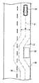
次に図2A及び図2Bを参照して、第1実施形態に係る運転支援装置1が適用される運転シーンを説明する。片側1車線道路において、自車両60が走行する第1車線L1(自車線)において自車両60の前方に障害物(以下「第1障害物」と表記することがある)61が存在する。
また、第1車線L1に隣接する隣接車線(対向車線)である第2車線L2には対向車両64が走行しており、自車両60に接近している。一点鎖線65は、対向車両64の右端が通りうる予想軌道を示し、一点鎖線66は対向車両64の左端が通りうる予想軌道を示す。予想軌道65と予想軌道66により挟まれた領域は、走行する対向車両64の車体全体が通りうる領域であり、以下「走行領域」と表記する。
図2Aに示すように、対向車両64が接近している場合には、自車両60は車線境界線(センターライン)を越えて第1障害物61を回避することができないため、停車して自車両60と対向車両64とのすれ違いが完了するのを待つ必要がある。
このような状況で、第2車線L2において自車両の進行方向で(第1車線L1における進行方向で)第1障害物61よりも手前側(図2A及び図2Bにおいて下側)に障害物(以下「第2障害物」と表記することがある)62が存在すると、第1障害物61の手前の位置63に停車した自車両60が、第2障害物62を回避する対向車両64の走行領域に干渉するおそれがある。この結果、対向車両64の走行が妨害されるおそれがある。
このような状況で、第2車線L2において自車両の進行方向で(第1車線L1における進行方向で)第1障害物61よりも手前側(図2A及び図2Bにおいて下側)に障害物(以下「第2障害物」と表記することがある)62が存在すると、第1障害物61の手前の位置63に停車した自車両60が、第2障害物62を回避する対向車両64の走行領域に干渉するおそれがある。この結果、対向車両64の走行が妨害されるおそれがある。
このため、コントローラ40は、図2Bに示すように自車両60が第2障害物62よりも進行方向で手前側の位置において、対向車両64が接近しており、第2障害物62が第1障害物61よりも自車両60に近い場合には、第2障害物62よりも手前の停車位置(以下「第1停車位置」と表記する)67に自車両60の停車位置を決定する。
このように、第2障害物62よりも手前の第1停車位置67に自車両60が停車すれば、第2障害物62を回避する対向車両64の走行を自車両60が妨害するのを防ぐことができる。すなわち、自車両60と第2車線L2上の第2障害物62が対向車両64の走行を妨害するのを防ぐことができる。
このように、第2障害物62よりも手前の第1停車位置67に自車両60が停車すれば、第2障害物62を回避する対向車両64の走行を自車両60が妨害するのを防ぐことができる。すなわち、自車両60と第2車線L2上の第2障害物62が対向車両64の走行を妨害するのを防ぐことができる。
図3を参照する。運転支援装置1のコントローラ40は、第1障害物検出部80と、対向車両検出部81と、第2障害物検出部82と、対向車両走行軌道推定部83と、干渉判断部84と、停止位置決定部85と、軌道生成部86を備える。第1障害物検出部80、対向車両検出部81、第2障害物検出部82、対向車両走行軌道推定部83、干渉判断部84、停止位置決定部85、及び軌道生成部86の機能は、例えばコントローラ40のプロセッサ41が、記憶装置42に格納されたコンピュータプログラムを実行することによって実現されてよい。
第1障害物検出部80は、周囲センサ群10から出力される周囲環境情報を受信する。第1障害物検出部80は、周囲環境情報から、自車両60が走行する第1車線L1上で、且つ自車両60の進路前方に存在する第1障害物61を検出(特定)し、第1障害物61の位置等の情報を第1障害物情報として取得する。なお、ナビゲーションシステム20の通信部27は、車車間通信や路車間通信により、他車両が検出した第1障害物61の位置等の情報を受信してもよい。第1障害物検出部80は、通信部27が受信した情報を第1障害物情報として取得してもよい。
本明細書において「障害物」とは、自車両60が回避すべき回避対象であり、例えば乗用車、大型トラック、二輪車等の駐車中、停車中、減速中の車両や、車両以外の静止物体、又は道路の規定車速に対して低速の移動体を含む。車両以外の静止物体は、道路上の工事現場等の仮設物や落下物を含む。低速の移動体は、自転車、歩行者、動物を含む。
第1障害物検出部80は、第1障害物情報を、対向車両走行軌道推定部83と、干渉判断部84と、停止位置決定部85へ出力する。
第1障害物検出部80は、第1障害物情報を、対向車両走行軌道推定部83と、干渉判断部84と、停止位置決定部85へ出力する。
対向車両検出部81は、周囲センサ群10から出力される周囲環境情報を受信する。第1障害物検出部80は、周囲環境情報から、第1車線L1に隣接する対向車線である第2車線L2を走行して自車両60へ接近する対向車両64を検出(特定)し、対向車両64の位置等の情報を対向車両情報として取得する。
また、対向車両検出部81は、測距装置11が測定した対向車両64の点群データや、カメラ12が撮影した対向車両64の画像に基づいて、対向車両64の大きさ(前後方向長さや車幅)や姿勢(例えばヨー角)を検出(特定)し、対向車両64の大きさや姿勢の情報を対向車両情報として取得してもよい。
また、対向車両検出部81は、測距装置11が測定した対向車両64の点群データや、カメラ12が撮影した対向車両64の画像に基づいて、対向車両64の大きさ(前後方向長さや車幅)や姿勢(例えばヨー角)を検出(特定)し、対向車両64の大きさや姿勢の情報を対向車両情報として取得してもよい。
また、対向車両検出部81は、カメラ12が撮影した対向車両64の画像に基づいて、対向車両64の車種の情報を対向車両情報として取得してもよい。
例えば対向車両検出部81は、コントローラ40の記憶装置42等に予め記憶した様々な車両の画像とカメラ12が撮影した対向車両64の画像とのパターンマッチングによって対向車両64の車種を特定してよい。また、例えば対向車両検出部81は、カメラ12が撮影した対向車両64の画像を、通信部27を介して外部装置(例えばサーバ装置等)へ送信し、外部装置が対向車両64の画像に基づいて特定した対向車両64の車種の情報を通信部27により受信してもよい。
例えば対向車両検出部81は、コントローラ40の記憶装置42等に予め記憶した様々な車両の画像とカメラ12が撮影した対向車両64の画像とのパターンマッチングによって対向車両64の車種を特定してよい。また、例えば対向車両検出部81は、カメラ12が撮影した対向車両64の画像を、通信部27を介して外部装置(例えばサーバ装置等)へ送信し、外部装置が対向車両64の画像に基づいて特定した対向車両64の車種の情報を通信部27により受信してもよい。
対向車両検出部81は、対向車両64の車種に基づいて、対向車両64の大きさの情報を対向車両情報として取得してもよい。例えばコントローラ40の記憶装置42等には、様々な車両の車種と大きさの情報とを関連付けたデータベースを記憶されていてよい。対向車両検出部81は、データベースと対向車両64の車種に基づいて、対向車両64の大きさを特定してよい。
また、例えば対向車両検出部81は、対向車両64の車種の情報を、通信部27を介して外部装置(例えばサーバ装置等)へ送信し、外部装置が対向車両64の車種に基づいて特定した対向車両64の大きさの情報を通信部27により受信してもよい。
また、例えば対向車両検出部81は、対向車両64の車種の情報を、通信部27を介して外部装置(例えばサーバ装置等)へ送信し、外部装置が対向車両64の車種に基づいて特定した対向車両64の大きさの情報を通信部27により受信してもよい。
さらに、対向車両検出部81は、対向車両64の運転技能レベルの情報を対向車両情報として取得してもよい。対向車両検出部81は、車車間通信や路車間通信により、対向車両64から受信してもよい。対向車両64は、対向車両64の運転者の運転履歴に基づいて対向車両64の運転技能レベルを算出するコントローラを備えてよい。例えば、運転技能レベルは、運転者の操舵操作の緩急、アクセル操作の緩急、ブレーキ操作の緩急、車間距離等の運転履歴に基づいて算出されてよい。
さらに、対向車両検出部81は、対向車両64の車種に基づいて、対向車両64が自動運転車であるか否かを判断し、対向車両64の自動運転の運転技能レベルや制御内容の情報を、対向車両64の運転技能レベルの情報として取得してもよい。例えばコントローラ40の記憶装置42等には、様々な車両の車種と自動運転機能に関する情報とを関連付けたデータベースを記憶されていてよい。対向車両検出部81は、データベースと対向車両64の車種に基づいて、対向車両64が自動運転車であるか否かを判断し、対向車両64の自動運転の運転技能レベルや制御内容の情報を特定してよい。
また、例えば対向車両検出部81は、対向車両64の車種の情報を、通信部27を介して外部装置(例えばサーバ装置等)へ送信し、対向車両64の車種に基づいて外部装置が特定した自動運転の運転技能レベルや制御内容の情報を、通信部27により受信してもよい。
なお、通信部27は、対向車両64の位置、大きさ、姿勢、車種の情報を車車間通信や路車間通信により、対向車両64等の他車両から受信してもよい。対向車両検出部81は、通信部27が受信した情報を対向車両情報として取得してもよい。
対向車両検出部81は、対向車両情報を対向車両走行軌道推定部83と停止位置決定部85へ出力する。
なお、通信部27は、対向車両64の位置、大きさ、姿勢、車種の情報を車車間通信や路車間通信により、対向車両64等の他車両から受信してもよい。対向車両検出部81は、通信部27が受信した情報を対向車両情報として取得してもよい。
対向車両検出部81は、対向車両情報を対向車両走行軌道推定部83と停止位置決定部85へ出力する。
第2障害物検出部82は、周囲センサ群10から出力される周囲環境情報を受信する。第2障害物検出部82は、周囲環境情報から、対向車線である第2車線L2上で、且つ自車両60の進路前方に存在する第2障害物62を検出(特定)し、第2障害物62の位置等の情報を第2障害物情報として取得する。なお、ナビゲーションシステム20の通信部27は、車車間通信や路車間通信により、他車両が検出した第2障害物62の位置等の情報を受信してもよい。第2障害物検出部82は、通信部27が受信した情報を第2障害物情報として取得してもよい。
第2障害物検出部82は、第2障害物情報を、対向車両走行軌道推定部83と停止位置決定部85へ出力する。
第2障害物検出部82は、第2障害物情報を、対向車両走行軌道推定部83と停止位置決定部85へ出力する。
対向車両走行軌道推定部83は、第1障害物情報と第2障害物情報に基づいて、第2車線L2の第2障害物62が、第1車線L1の第1障害物61よりも自車両60に近いか否かを判断する。すなわち対向車両走行軌道推定部83は、第2障害物62と自車両60との間の前後方向距離(すなわち進行方向距離)が第1障害物61と自車両60との間の前後方向距離よりも短いか否かを判断する。
対向車両走行軌道推定部83は、第2障害物62が第1障害物61よりも自車両60に近いか否かの判断結果を停止位置決定部85へ出力する。
対向車両走行軌道推定部83は、第2障害物62が第1障害物61よりも自車両60に近いか否かの判断結果を停止位置決定部85へ出力する。
第2障害物62が第1障害物61よりも自車両60に近い場合、対向車両走行軌道推定部83は、対向車両64が将来走行すると予測される予測走行軌道を推定する。
例えば対向車両走行軌道推定部83は、周囲センサ群10から出力される周囲環境情報と、第1障害物情報と、第2障害物情報と、対向車両情報に基づいて、対向車両64の予測走行軌道を推定してよい。例えば図2A及び図2Bに示す運転シーンでは、対向車両走行軌道推定部83は、第2車線L2の第2障害物62を回避する対向車両64の予測走行軌道を推定する。
例えば対向車両走行軌道推定部83は、周囲センサ群10から出力される周囲環境情報と、第1障害物情報と、第2障害物情報と、対向車両情報に基づいて、対向車両64の予測走行軌道を推定してよい。例えば図2A及び図2Bに示す運転シーンでは、対向車両走行軌道推定部83は、第2車線L2の第2障害物62を回避する対向車両64の予測走行軌道を推定する。
例えば対向車両走行軌道推定部83は、周囲環境情報から、第2車線L2の車線境界を検出してよい。対向車両走行軌道推定部83は、第2車線L2の車線境界の位置、対向車両64の移動履歴、対向車両64の姿勢の履歴、対向車両64の車速、対向車両64と第1障害物61との間の相対位置関係、対向車両64と第2障害物62との間の相対位置関係等に基づき、対向車両64の予測走行軌道を推定してよい。
図4を参照する。一点鎖線91は、対向車両64の予測走行軌道を示す。対向車両走行軌道推定部83は、対向車両64の予測走行軌道91に基づいて、対向車両64の右端が通りうる予想軌道65と対向車両64の左端が通りうる予想軌道66とに挟まれた対向車両64の走行領域を予測する。
例えば、対向車両走行軌道推定部83は、予測走行軌道91に沿って延伸し予測走行軌道91を中心とする幅Wの領域を走行領域として推定してよい。
例えば、対向車両走行軌道推定部83は、予測走行軌道91に沿って延伸し予測走行軌道91を中心とする幅Wの領域を走行領域として推定してよい。
対向車両走行軌道推定部83は、対向車両検出部81が検出した車幅に所定のマージンを加えた長さを幅Wとして設定してよい。例えば対向車両走行軌道推定部83は、対向車両検出部81が取得した対向車両64の運転技能レベル等に応じて対向車両64の走行領域のマージンを変化させてよい。すなわち、対向車両走行軌道推定部83は、対向車両64の運転技能レベル等に基づいて対向車両64の走行領域を推定してよい。
例えば、対向車両64の運転技能レベルが低い場合(例えば、対向車両64の運転者や自動運転の運転技能レベルが低い場合や、自動運転の制御内容の性能、品質が低い場合)には、対向車両64の走行軌道の予想が難しくなり、予測走行軌道91の変動が大きくなると考えられる。この場合には、走行領域のマージンを大きくして走行領域の幅Wを増加してよい。
反対に対向車両64の運転技能レベルが高い場合には、対向車両64の走行軌道を高い精度で予想できると考えられるので、走行領域のマージンを小さくして走行領域の幅Wを低減してよい。
図3を参照する。対向車両走行軌道推定部83は、推定した対向車両64の走行領域の情報を干渉判断部84に出力する。
図3を参照する。対向車両走行軌道推定部83は、推定した対向車両64の走行領域の情報を干渉判断部84に出力する。
干渉判断部84は、対向車両64の走行領域の情報と、第1障害物情報とに基づいて、自車両60を第1障害物61の手前に停車させた場合に自車両60が対向車両64の走行領域に干渉する可能性があるか否かを判断する。
図2Aを参照する。例えば干渉判断部84は、第1障害物情報が示す第1障害物61の前後方向位置(すなわち自車両60の進行方向における位置であり、以下では進行方向位置とも記載する)に基づいて、第1障害物61の手前で自車両60が停車して自車両60と対向車両64とがすれ違う停車位置63を決定する。例えば干渉判断部84は、停車位置63に停車した自車両60と対向車両64とがすれ違った後に、スムーズな操舵で自車両60が第1障害物61を追い越すことができるように、停車位置63の前後方向位置や横方向位置(すなわち車幅方向位置)を決定してよい。
図2Aを参照する。例えば干渉判断部84は、第1障害物情報が示す第1障害物61の前後方向位置(すなわち自車両60の進行方向における位置であり、以下では進行方向位置とも記載する)に基づいて、第1障害物61の手前で自車両60が停車して自車両60と対向車両64とがすれ違う停車位置63を決定する。例えば干渉判断部84は、停車位置63に停車した自車両60と対向車両64とがすれ違った後に、スムーズな操舵で自車両60が第1障害物61を追い越すことができるように、停車位置63の前後方向位置や横方向位置(すなわち車幅方向位置)を決定してよい。
さらに干渉判断部84は、例えば、自車両60の占有領域と対向車両64の走行領域とが重複するか否かに応じて、自車両60が対向車両64の走行領域に干渉する可能性があるか否かを判断してよい。例えば干渉判断部84は、停車位置63に停車した自車両60の占有領域と対向車両64の走行領域とが重複する場合、自車両60が対向車両64の走行領域に干渉する可能性があると判断してよい。例えば干渉判断部84は、自車両60の占有領域と対向車両64の走行領域とが重複しない場合、自車両60が対向車両64の走行領域に干渉する可能性がないと判断してよい。
図3を参照する。干渉判断部84は、自車両60が対向車両64の走行領域に干渉する可能性の判断結果を停止位置決定部85に出力する。
図3を参照する。干渉判断部84は、自車両60が対向車両64の走行領域に干渉する可能性の判断結果を停止位置決定部85に出力する。
停止位置決定部85は、干渉判断部84の判断結果に基づいて、自車両60と対向車両64とのすれ違いが完了するのを待つ停車位置を決定する。自車両60を第1障害物61の手前に停車させた場合に自車両60が対向車両64の走行領域に干渉する可能性がある場合には、停止位置決定部85は、第2障害物62よりも手前の第1停車位置67(図2B参照)を自車両60の停止位置として決定する。
例えば停止位置決定部85は、第1停車位置67の前後方向位置(すなわち進行方向位置)、例えば第2障害物62と自車両60の前後方向距離(すなわち進行方向距離)を、第1停車位置67に停車した自車両60が、第2障害物62を回避して第2車線L2へ戻る対向車両64の走行領域に干渉しないように決定してよい。
例えば停止位置決定部85は、第1停車位置67の前後方向位置を、対向車両64の走行領域が第1車線L1にはみ出している区間よりも手前に決定してよい。
例えば停止位置決定部85は、第1停車位置67の前後方向位置を、対向車両64の走行領域が第1車線L1にはみ出している区間よりも手前に決定してよい。
図5Aを参照する。第1障害物61が第2障害物62よりも自車両60に近いと対向車両走行軌道推定部83が判断した場合、停止位置決定部85は、第1障害物情報が示す第1障害物61の前後方向位置(すなわち進行方向位置)に基づいて、停車位置90を決定する。自車両60は、この停車位置90にて自車両60と対向車両64とのすれ違いの完了を待つ。停止位置決定部85は、例えば、自車両60が第1障害物61を回避可能な程度の所定の距離だけ第1障害物61から手前の位置に停車位置90を設定してよい。
図5Bを参照する。自車両60が対向車両64の走行領域に干渉しないように第1障害物61の手前に自車両60を停車させる停車位置90が存在する場合にも、停止位置決定部85は、第1障害物情報が示す第1障害物61の前後方向位置(すなわち進行方向位置)に基づいて停車位置90を決定する。
図5A及び図5Bに示すように第1障害物61の手前に停車位置90を決定する場合、干渉判断部84は、停車位置90に停車した自車両60と対向車両64とがすれ違った後に、スムーズな操舵で自車両60が第1障害物61を追い越す(回避する)ことができるように、停車位置90の前後方向位置や横方向位置(すなわち車幅方向位置)を決定してよい。なお、停車位置90の前後方向位置や横方向位置は第1障害物61に対して、自車両60が第1障害物61を回避することが充分可能な程度の距離を確保した予め定められた位置であっても良いし、自車両60が第1障害物61をスムーズな操舵で回避する際の走行領域を算出して、算出した走行領域に基づいて設定した位置であっても良い。
図5A及び図5Bに示すように第1障害物61の手前に停車位置90を決定する場合、干渉判断部84は、停車位置90に停車した自車両60と対向車両64とがすれ違った後に、スムーズな操舵で自車両60が第1障害物61を追い越す(回避する)ことができるように、停車位置90の前後方向位置や横方向位置(すなわち車幅方向位置)を決定してよい。なお、停車位置90の前後方向位置や横方向位置は第1障害物61に対して、自車両60が第1障害物61を回避することが充分可能な程度の距離を確保した予め定められた位置であっても良いし、自車両60が第1障害物61をスムーズな操舵で回避する際の走行領域を算出して、算出した走行領域に基づいて設定した位置であっても良い。
図3を参照する。停止位置決定部85は、決定した自車両60の停車位置の情報を軌道生成部86へ出力する。
軌道生成部86は、周囲センサ群10から出力される周囲環境情報、ナビゲーションシステム20から出力される道路地図データ及び走行経路、車両センサ群30から出力される車両情報等に基づいて、自車両に走行させる走行軌道を生成する。
軌道生成部86は、周囲センサ群10から出力される周囲環境情報、ナビゲーションシステム20から出力される道路地図データ及び走行経路、車両センサ群30から出力される車両情報等に基づいて、自車両に走行させる走行軌道を生成する。
軌道生成部86は、自車両60が第1障害物61を回避する前に停車して対向車両64とのすれ違いの完了を待つために、停止位置決定部85が決定した停車位置へ到達するための走行軌道を生成する。
軌道生成部86は、車両センサ群30から出力される車両情報等に基づいて、自車両が停車位置で停止したり、停車位置を減速して通過したりするための速度のプロファイルを含むように走行軌道を生成してもよい。軌道生成部86は、生成した走行軌道を走行制御装置50へ出力する。
軌道生成部86は、車両センサ群30から出力される車両情報等に基づいて、自車両が停車位置で停止したり、停車位置を減速して通過したりするための速度のプロファイルを含むように走行軌道を生成してもよい。軌道生成部86は、生成した走行軌道を走行制御装置50へ出力する。
走行制御装置50は、軌道生成部86により生成された走行軌道に基づき、停止位置決定部85が決定した停車位置まで自車両60を走行させて、自車両60を停車位置させることによって運転支援を行う。
例えば、第2障害物62が第1障害物61よりも自車両60進行方向で手前側に存在し、自車両60を第1障害物61の手前に停車させた場合に自車両60が対向車両64の走行領域に干渉する可能性がある場合には、図2Bに示すように第2障害物62よりも自車両60進行方向で手前の第1停車位置67まで自車両60を走行させ、自車両60を第1停車位置67に停車させる。
例えば、第2障害物62が第1障害物61よりも自車両60進行方向で手前側に存在し、自車両60を第1障害物61の手前に停車させた場合に自車両60が対向車両64の走行領域に干渉する可能性がある場合には、図2Bに示すように第2障害物62よりも自車両60進行方向で手前の第1停車位置67まで自車両60を走行させ、自車両60を第1停車位置67に停車させる。
このように第2障害物62よりも手前で自車両60が待機すれば、第2障害物62を回避する対向車両64の走行を妨害するのを防止できる。
また、例えば第1障害物61が第2障害物62よりも自車両60進行方向で手前側に存在する場合には、図5Aに示すように第1障害物61の位置を基準に、第1障害物61から自車両60進行方向で手前側に決定した停車位置90で自車両60が停車しても、第2障害物62を回避する対向車両64の走行を妨害しない。
また、例えば第1障害物61が第2障害物62よりも自車両60進行方向で手前側に存在する場合には、図5Aに示すように第1障害物61の位置を基準に、第1障害物61から自車両60進行方向で手前側に決定した停車位置90で自車両60が停車しても、第2障害物62を回避する対向車両64の走行を妨害しない。
図5Bに示すように自車両60が対向車両64の走行領域に干渉しないように第1障害物61の手前に自車両60を停車させる停車位置90が存在する場合も同様である。これらの場合に走行制御装置50は、第1障害物61の前後方向位置(すなわち進行方向位置)に基づいて決定された停車位置90まで自車両60を走行させ、自車両60を停車位置90に停車させる。
(運転支援方法)
次に、図6のフローチャートを参照して、第1実施形態に係る運転支援方法の一例を説明する。
ステップS1において第1障害物検出部80は、第1車線L1において自車両60の進路前方に第1障害物61が存在するか否かを判断する。第1障害物61が存在する場合(ステップS1:Y)に処理はステップS3へ進む。第1障害物61が存在しない場合(ステップS1:N)に処理はステップS2へ進む。
次に、図6のフローチャートを参照して、第1実施形態に係る運転支援方法の一例を説明する。
ステップS1において第1障害物検出部80は、第1車線L1において自車両60の進路前方に第1障害物61が存在するか否かを判断する。第1障害物61が存在する場合(ステップS1:Y)に処理はステップS3へ進む。第1障害物61が存在しない場合(ステップS1:N)に処理はステップS2へ進む。
ステップS2において軌道生成部86は、第1車線L1を直進する走行軌道を生成する。その後に処理はステップS12へ進む。
ステップS3において対向車両検出部81は、対向車線である第2車線L2を走行して自車両60へ接近する対向車両64が存在するか否かを判断する。対向車両64が存在する場合(ステップS3:Y)に処理はステップS5へ進む。対向車両64が存在しない場合(ステップS3:N)に処理はステップS4へ進む。
ステップS3において対向車両検出部81は、対向車線である第2車線L2を走行して自車両60へ接近する対向車両64が存在するか否かを判断する。対向車両64が存在する場合(ステップS3:Y)に処理はステップS5へ進む。対向車両64が存在しない場合(ステップS3:N)に処理はステップS4へ進む。
ステップS4において軌道生成部86は、第1車線L1の第1障害物61を回避して走行する走行軌道を生成する。その後に処理はステップS12へ進む。
ステップS5において第2障害物検出部82は、第2車線L2において自車両60の進路前方に第2障害物62が存在するか否かを判断する。第2障害物62が存在する場合(ステップS5:Y)に処理はステップS6へ進む。第2障害物62が存在しない場合(ステップS5:N)に処理はステップS10へ進む。
ステップS5において第2障害物検出部82は、第2車線L2において自車両60の進路前方に第2障害物62が存在するか否かを判断する。第2障害物62が存在する場合(ステップS5:Y)に処理はステップS6へ進む。第2障害物62が存在しない場合(ステップS5:N)に処理はステップS10へ進む。
ステップS6において対向車両走行軌道推定部83は、第2車線L2の第2障害物62の位置が、第1車線L1の第1障害物61の位置よりも自車両60進行方向で手前側であるか否かを判断する。第2障害物62の位置が第1障害物61の位置よりも自車両60進行方向で手前側である場合(ステップS6:Y)に処理はステップS7へ進む。第1障害物61が第2障害物62よりも自車両60に近い場合(ステップS6:N)に処理はステップS10へ進む。
ステップS7において対向車両走行軌道推定部83は、第2障害物62を回避して走行する対向車両64の予測走行軌道91を推定し、予測走行軌道91に基づいて、第2障害物62を回避して走行する対向車両64の走行領域を推定する。
ステップS8において干渉判断部84は、自車両60を第1障害物61の手前に停車させた場合に自車両60が対向車両64の走行領域に干渉する可能性があるか否かを判断する。
ステップS8において干渉判断部84は、自車両60を第1障害物61の手前に停車させた場合に自車両60が対向車両64の走行領域に干渉する可能性があるか否かを判断する。
自車両60が対向車両64の走行領域に干渉する可能性がある場合(ステップS8:Y)に処理はステップS9へ進む。対向車両64の走行領域に干渉せずに第1障害物61の手前に停車させることができる場合(ステップS8:N)に処理はステップS10へ進む。
ステップS9において停止位置決定部85は、第2車線L2の第2障害物62の位置を基準に、自車両60を停車させる第1停車位置67の前後方向位置(すなわち進行方向位置)を決定する。例えば停止位置決定部85は、第2障害物62の手前に第1停車位置67の前後方向位置を決定する。その後に処理はステップS11に進む。
ステップS9において停止位置決定部85は、第2車線L2の第2障害物62の位置を基準に、自車両60を停車させる第1停車位置67の前後方向位置(すなわち進行方向位置)を決定する。例えば停止位置決定部85は、第2障害物62の手前に第1停車位置67の前後方向位置を決定する。その後に処理はステップS11に進む。
ステップS10において停止位置決定部85は、第1車線L1の第1障害物61の位置を基準に、自車両60を停車させる停車位置90の前後方向位置(すなわち進行方向位置)を決定する。その後に処理はステップS11に進む。
ステップS11において軌道生成部86は、停止位置決定部85が決定した停車位置へ到達するための走行軌道を生成する。
ステップS12において走行制御装置50は、軌道生成部86により生成された走行軌道に基づき、停止位置決定部85が決定した停車位置まで自車両60を走行させて、自車両60を停車位置で停車させる運転支援を行う。その後に処理は終了する。
なお、上述した実施形態においては運転支援方法として、走行制御装置50が自車両60を停止位置決定部85が決定した停車位置で停車させる態様を記載したがこれに限らない。例えば停止位置決定部85が決定した停車位置をナビゲーション画面に表示する等によって自車両60の運転者に停車位置を提示して、自車両60の停止位置への停車を支援しても良い。
(第1実施形態の効果)
(1)第1障害物検出部80は、自車両60が走行する第1車線L1において自車両60の進行方向前方の第1障害物61の位置を検出する。第2障害物検出部82は、第1車線L1に隣接する対向車線である第2車線L2において自車両60の進行方向前方の第2障害物62の位置を検出する。第2障害物62の位置が第1障害物61の位置よりも自車両60の進行方向で手前側である場合に、停止位置決定部85は、自車両60の停車位置を第2障害物62よりも手前の第1停車位置67に決定し、自車両60の第1停車位置67への停車を支援する。
(1)第1障害物検出部80は、自車両60が走行する第1車線L1において自車両60の進行方向前方の第1障害物61の位置を検出する。第2障害物検出部82は、第1車線L1に隣接する対向車線である第2車線L2において自車両60の進行方向前方の第2障害物62の位置を検出する。第2障害物62の位置が第1障害物61の位置よりも自車両60の進行方向で手前側である場合に、停止位置決定部85は、自車両60の停車位置を第2障害物62よりも手前の第1停車位置67に決定し、自車両60の第1停車位置67への停車を支援する。
このような位置に自車両60を停車させることにより、第2障害物62を回避する対向車両64の走行を妨げることなく、自車両60と対向車両64とのすれ違いを待つことができる。すなわち、自車両60の前方の障害物に応じて停車した自車両60と対向車線L2上の第2障害物62が対向車両64の走行を妨害するのを防ぐことができる。このため、交通を妨げるおそれがなくなる。このように、自車両60の自動運転の走行軌道の品質が向上した、改良された走行軌道生成技術を提供できる。
対向車両64の走行を妨害する位置に停車してしまった後に自車両60をバックさせて対向車両64を通行させるなどの無駄な運転を防ぐことができるので、自車両60の燃費向上に貢献する。
対向車両64の走行を妨害する位置に停車してしまった後に自車両60をバックさせて対向車両64を通行させるなどの無駄な運転を防ぐことができるので、自車両60の燃費向上に貢献する。
(2)第2障害物62の位置が第1障害物61の位置よりも自車両60の進行方向で手前側であって、且つ自車両60が第1障害物61の手前で停車した場合に対向車両64の走行領域に干渉する可能性がある場合に、停止位置決定部85は、自車両60の停車位置を第1停車位置67に決定してよい。
これにより、対向車両64の走行を妨害するか否かに基づいて、自車両60の停車位置を切り替えることができるので、第2障害物62を回避する対向車両64の走行を妨げることなく、自車両60と対向車両64とのすれ違いを待つことができる。
これにより、対向車両64の走行を妨害するか否かに基づいて、自車両60の停車位置を切り替えることができるので、第2障害物62を回避する対向車両64の走行を妨げることなく、自車両60と対向車両64とのすれ違いを待つことができる。
(3)対向車両走行軌道推定部83は、対向車両64の走行領域を推定してよい。干渉判断部84は、推定した走行領域と第1障害物61の手前で停車した場合の自車両60の占有領域とが重複するか否かに応じて、自車両60が対向車両64の走行領域に干渉する可能性を判断してよい。
これにより、停車中の自車両60が対向車両64の走行領域に干渉する可能性があるか否かを判定できる。
これにより、停車中の自車両60が対向車両64の走行領域に干渉する可能性があるか否かを判定できる。
(4)対向車両検出部81は、対向車両64の運転技能レベルを判断してよい。対向車両走行軌道推定部83は、運転技能レベルに応じて対向車両64の走行領域を推定してよい。
これにより、対向車両64の運転技能レベルが低くても安全な位置で自車両60を待機させることができる。
これにより、対向車両64の運転技能レベルが低くても安全な位置で自車両60を待機させることができる。
(5)第2障害物62が第1障害物61よりも自車両60から遠い場合に、停止位置決定部85は、第1障害物61の前後方向位置(すなわち進行方向位置)を基準に自車両60の停車位置を決定してよい。
第2障害物62が第1障害物61よりも自車両60から遠い場合には、第1障害物61の手前の任意の位置で停車しても、第2障害物62を回避する対向車両64の走行と自車両60とは干渉しない。したがってこの場合には、対向車両64とすれ違う前に第1障害物61により近い位置まで自車両60を進めることにより、より速やかに第1障害物61を回避することができる。
第2障害物62が第1障害物61よりも自車両60から遠い場合には、第1障害物61の手前の任意の位置で停車しても、第2障害物62を回避する対向車両64の走行と自車両60とは干渉しない。したがってこの場合には、対向車両64とすれ違う前に第1障害物61により近い位置まで自車両60を進めることにより、より速やかに第1障害物61を回避することができる。
(第2実施形態)
第2実施形態に係る運転支援装置1の構成は、図1に示した第1実施形態に係る運転支援装置1の構成と基本的に同様である。また、第2実施形態に係るコントローラ40の機能構成は、図3に示したコントローラ40の機能構成と基本的に同様である。
図7を参照する。第2実施形態に係る運転支援装置1は、第1実施形態と同様に、第1停車位置67に停車した自車両60が、第2障害物62を回避して第2車線L2へ戻る対向車両64の走行領域に干渉しないように第1停車位置67を決定する。
第2実施形態に係る運転支援装置1の構成は、図1に示した第1実施形態に係る運転支援装置1の構成と基本的に同様である。また、第2実施形態に係るコントローラ40の機能構成は、図3に示したコントローラ40の機能構成と基本的に同様である。
図7を参照する。第2実施形態に係る運転支援装置1は、第1実施形態と同様に、第1停車位置67に停車した自車両60が、第2障害物62を回避して第2車線L2へ戻る対向車両64の走行領域に干渉しないように第1停車位置67を決定する。
次に第2実施形態に係る運転支援装置1は、対向車両64の大きさを判断する。運転支援装置1は対向車両64の大きさとして、例えば対向車両64の前後方向長さLを判断してよく、対向車両64の車幅を判断してもよい。対向車両64の大きさが閾値を超える場合に、第2障害物62から自車両60の進行方向でより手前側の位置92に第1停車位置を補正する。すなわち、対向車両64の大きさが閾値を超える場合に、第2障害物62から自車両60の進行方向でより手前側に第1停車位置を補正する。
このように対向車両64の大きさが閾値を超える場合には対向車両64の大きさが閾値を超えない場合に対して、第2障害物62から自車両60の進行方向でより手前側に第1停車位置を設定することにより、対向車両64が第2障害物62を回避するために第1車線L1へはみ出す位置(又は第1車線L1に接近した位置)から離れた場所で、対向車両64と自車両60とのすれ違いの完了を待つことができる。これにより、例えば、トラックや大型トレーラ等の大型の対向車両64とすれ違う場合に乗員が感じる恐怖を軽減できる。
このように対向車両64の大きさが閾値を超える場合には対向車両64の大きさが閾値を超えない場合に対して、第2障害物62から自車両60の進行方向でより手前側に第1停車位置を設定することにより、対向車両64が第2障害物62を回避するために第1車線L1へはみ出す位置(又は第1車線L1に接近した位置)から離れた場所で、対向車両64と自車両60とのすれ違いの完了を待つことができる。これにより、例えば、トラックや大型トレーラ等の大型の対向車両64とすれ違う場合に乗員が感じる恐怖を軽減できる。
具体的には、図3に示す停止位置決定部85は、第1停車位置67の前後方向位置(すなわち進行方向位置)を、第1停車位置67に停車した自車両60が、第2障害物62を回避して第2車線L2へ戻る対向車両64の走行領域に干渉しないように決定する。
次に停止位置決定部85は、対向車両検出部81が出力する対向車両情報に基づいて、対向車両64の大きさが所定の閾値を超えるか否かを判断する。
対向車両64の大きさが所定の閾値を超える場合には対向車両64の大きさが閾値を超えない場合に対して、停止位置決定部85は第1停車位置を、第2障害物62から自車両60の進行方向でより手前側の位置92に補正する。
次に停止位置決定部85は、対向車両検出部81が出力する対向車両情報に基づいて、対向車両64の大きさが所定の閾値を超えるか否かを判断する。
対向車両64の大きさが所定の閾値を超える場合には対向車両64の大きさが閾値を超えない場合に対して、停止位置決定部85は第1停車位置を、第2障害物62から自車両60の進行方向でより手前側の位置92に補正する。
次に、図8のフローチャートを参照して、第2実施形態に係る運転支援方法の一例を説明する。ステップS21~S29の処理は、図6を参照して説明したステップS1~S9の処理と同様である。ステップS32~S34の処理は、図6を参照して説明したステップS10~S12の処理と同様である。
ステップS29において停止位置決定部85が、第2障害物62の位置を基準に第1停車位置67の前後方向位置を決定した後、処理はステップS30へ進む。
ステップS29において停止位置決定部85が、第2障害物62の位置を基準に第1停車位置67の前後方向位置を決定した後、処理はステップS30へ進む。
ステップS30において停止位置決定部85は、対向車両64の大きさが閾値以下か否かを判断する。対向車両64の大きさが閾値以下の場合(ステップS30:Y)に処理はステップS33へ進む。この場合には、ステップS29で決定した第1停車位置67は補正されずに、自車両60の停車位置として決定される。
対向車両64の大きさが閾値を超える場合(ステップS30:N)に処理はステップS31へ進む。
対向車両64の大きさが閾値を超える場合(ステップS30:N)に処理はステップS31へ進む。
ステップS31において停止位置決定部85は、ステップS29で決定した第1停車位置67を後方へずらす。
すなわち停止位置決定部85は、第2障害物62からより遠くなる位置92に、第1停車位置を補正する。その後に処理はステップS33へ進む。
すなわち停止位置決定部85は、第2障害物62からより遠くなる位置92に、第1停車位置を補正する。その後に処理はステップS33へ進む。
(第2実施形態の効果)
対向車両検出部81は、対向車両64の大きさを判断する。対向車両64の大きさが閾値を超える場合には対向車両64の大きさが閾値を超えない場合に対して、停止位置決定部85は第1停車位置を、第2障害物62から自車両60の進行方向でより手前側の位置に設定する。
このように第1停車位置を第2障害物62から自車両60の進行方向でより手前側の位置に設定することにより、第2障害物62を回避するために第1車線L1へ対向車両64がはみ出す位置(又は第1車線L1に接近した位置)から離れた場所で、対向車両64と自車両60とのすれ違いの完了を待つことができる。これにより、例えば、トラックや大型トレーラ等の大型の対向車両64とすれ違う場合に乗員が感じる恐怖を軽減できる。
(第3実施形態)
第3実施形態に係る運転支援装置1の構成は、図1に示した第1実施形態に係る運転支援装置1の構成と基本的に同様である。また、第3実施形態に係るコントローラ40の機能構成は、図3に示したコントローラ40の機能構成と基本的に同様である。
図9を参照する。第3実施形態に係るコントローラ40の干渉判断部84は、第1障害物61に対して自車両60の進行方向で手前の停車位置(以下「第2停車位置」と表記する)93に自車両60が停車した場合に第2障害物62を回避する対向車両64の走行領域に干渉する可能性があるか否かを判断する。第2停車位置93は、例えば図5A及び図5Bを参照して説明した停車位置90と同様に決定してよい。
第2停車位置93に停車した自車両60が対向車両64の走行領域に干渉する可能性がある場合に、停止位置決定部85は、第2車線L2から離れるように第2停車位置93を横方向(車線線幅方向)で対向車線64から離れる方向に移動した停車位置(以下「第3停車位置」と表記する)94を決定する。すなわち、車両の左側通行が義務づけられている場合には第2停車位置93を左へ移動して第3停車位置94を定める。車両の右側通行が義務づけられている場合には第2停車位置93を右へ移動して第3停車位置94を定める。
停止位置決定部85は、第3停車位置94に停車した自車両60が対向車両64の走行領域に干渉するか否かを判断する。
第3停車位置94に停車した自車両60が対向車両64の走行領域に干渉しない場合、停止位置決定部85は、自車両60の停車位置を第3停車位置94に決定する。自車両60は第1障害物61を回避する前に第3停車位置94に停車して、対向車両64とのすれ違いの完了を待つ。
第3停車位置94に停車した自車両60が対向車両64の走行領域に干渉しない場合、停止位置決定部85は、自車両60の停車位置を第3停車位置94に決定する。自車両60は第1障害物61を回避する前に第3停車位置94に停車して、対向車両64とのすれ違いの完了を待つ。
次に、図10のフローチャートを参照して、第3実施形態に係る運転支援方法の一例を説明する。ステップS41~S47の処理は、図6を参照して説明したステップS1~S7の処理と同様である。ステップS51~S54の処理は図6を参照して説明したステップS9~S12の処理と同様である。
ステップS47にて対向車両走行軌道推定部83が対向車両64の走行領域を推定した後、干渉判断部84は、第1障害物61の前後方向位置(すなわち進行方向位置)を基準にして、第1障害物61の手前に第2停車位置93を決定する。ステップS48にて干渉判断部84は、第2停車位置93に自車両60が停車した場合に、自車両60が対向車両64の走行領域に干渉する可能性があるか否かを判断する。
第2停車位置93に停車した自車両60が対向車両64の走行領域に干渉する可能性がある場合(ステップS48:Y)に処理はステップS49へ進む。第2停車位置93に停車した自車両60が対向車両64の走行領域に干渉しない場合(ステップS48:N)に処理はステップS52へ進む。
第2停車位置93に停車した自車両60が対向車両64の走行領域に干渉する可能性がある場合(ステップS48:Y)に処理はステップS49へ進む。第2停車位置93に停車した自車両60が対向車両64の走行領域に干渉しない場合(ステップS48:N)に処理はステップS52へ進む。
ステップS49において停止位置決定部85は、車線幅方向で第2車線L2から離れるように第2停車位置93を横方向に移動して第3停車位置94を定める。
停止位置決定部85は、第3停車位置94に停車した自車両60が対向車両64の走行領域に干渉するか否かを判断する。自車両60が対向車両64の走行領域に干渉する場合(ステップS49:Y)に処理はステップS51へ進む。この場合に停止位置決定部85は、第2障害物62の位置を基準に第1停車位置67の前後方向位置を決定する。
停止位置決定部85は、第3停車位置94に停車した自車両60が対向車両64の走行領域に干渉するか否かを判断する。自車両60が対向車両64の走行領域に干渉する場合(ステップS49:Y)に処理はステップS51へ進む。この場合に停止位置決定部85は、第2障害物62の位置を基準に第1停車位置67の前後方向位置を決定する。
自車両60が対向車両64の走行領域に干渉しない場合(ステップS49:N)に処理はステップS50へ進む。
ステップS50において停止位置決定部85は、第2車線L2から離れるように第2停車位置93を横方向にずらして定めた第3停車位置94を、自車両60の停車位置として決定する。その後に処理はステップS53へ進む。
ステップS50において停止位置決定部85は、第2車線L2から離れるように第2停車位置93を横方向にずらして定めた第3停車位置94を、自車両60の停車位置として決定する。その後に処理はステップS53へ進む。
(第3実施形態の効果)
干渉判断部84は、第1障害物61の手前の第2停車位置93に自車両60が停車した場合に第2障害物62を回避する対向車両64の走行領域に干渉する可能性があるか否かを判断する。第2停車位置93に停車した自車両60が対向車両64の走行領域に干渉する可能性がある場合に、停止位置決定部85は、車線幅方向で第2車線L2から離れるように第2停車位置93を横方向に移動して第3停車位置94を決定する。第3停車位置94に停車した場合の自車両60が対向車両64の走行領域に干渉しない場合、停止位置決定部85は、自車両60の停車位置を第3停車位置94に決定する。
これにより、対向車両64の走行を妨害しない位置に自車両60を停車させつつ、対向車両64とすれ違う前に第1障害物61により近い位置まで自車両60を進めることができるので、より速やかに第1障害物61を回避することができる。
ここに記載されている全ての例及び条件的な用語は、読者が、本発明と技術の進展のために発明者により与えられる概念とを理解する際の助けとなるように、教育的な目的を意図したものであり、具体的に記載されている上記の例及び条件、並びに本発明の優位性及び劣等性を示すことに関する本明細書における例の構成に限定されることなく解釈されるべきものである。本発明の実施例は詳細に説明されているが、本発明の精神及び範囲から外れることなく、様々な変更、置換及び修正をこれに加えることが可能であると解すべきである。
1…運転支援装置,2…走行軌道生成装置,10…周囲センサ群,11…測距装置,12…カメラ,20…ナビゲーションシステム,21…ナビコントローラ,22…測位装置,23…地図データベース,24…表示部,25…操作部,26…音声出力部,27…通信部,30…車両センサ群,31…車速センサ,32…加速度センサ,33…ジャイロセンサ,34…操舵角センサ,35…アクセルセンサ,36…ブレーキセンサ,40…コントローラ,41…プロセッサ,42…記憶装置,50…走行制御装置,51…アクチュエータ群,52…ステアリングアクチュエータ,53…アクセル開度アクチュエータ,54…ブレーキ制御アクチュエータ,60…自車両,第1車線…L1,61…第1障害物,L2…対向車線,62…第2障害物,64…対向車両,80…第1障害物検出部,81…対向車両検出部,82…第2障害物検出部,83…対向車両走行軌道推定部,84…干渉判断部,85…停止位置決定部,86…軌道生成部
Claims (8)
- 自車両が走行する第1車線において前記自車両の前方の第1障害物の位置を検出し、
前記第1車線に隣接する対向車線である第2車線において前記自車両の前方の第2障害物の位置を検出し、
前記第2障害物の位置が前記第1障害物の位置よりも前記自車両の進行方向で手前側である場合に、前記自車両の停車位置として前記第2障害物よりも前記自車両の進行方向で手前の位置に第1停車位置を決定し、
前記決定した第1停車位置への前記自車両の停車を支援する、
ことを特徴とする運転支援方法。 - 前記第2障害物の位置が前記第1障害物の位置よりも前記自車両の進行方向で手前側であって、且つ前記自車両が前記第1障害物の手前で停車した場合に対向車両の走行に干渉する可能性がある場合に、前記自車両の停車位置を前記第1停車位置に決定することを特徴とする請求項1に記載の運転支援方法。
- 前記対向車両の走行領域を推定し、
推定した前記走行領域と前記第1障害物の手前で停車した場合の前記自車両の占有領域とが重複するか否かに応じて、前記自車両が前記対向車両の走行に干渉する可能性を判断する、
ことを特徴とする請求項2に記載の運転支援方法。 - 前記対向車両の運転技能レベルを判断し、前記運転技能レベルに応じて前記走行領域を推定する請求項3に記載の運転支援方法。
- 前記対向車両の大きさを判断し、
前記対向車両の前記大きさが閾値を超える場合には前記対向車両の前記大きさが閾値を超えない場合よりも、前記第2障害物から前記自車両の進行方向で手前側に前記第1停車位置を設定する、
ことを特徴とする請求項2~4のいずれか一項に記載の運転支援方法。 - 前記第2障害物の位置が前記第1障害物の位置よりも前記自車両の進行方向で手前側であって、且つ前記自車両が前記第1障害物の手前の第2停車位置に停車した場合に前記対向車両の走行に干渉する可能性があっても、車線幅方向で前記第2車線から離れるように前記第2停車位置を横方向に移動して定めた第3停車位置に停車した場合の前記自車両が前記対向車両の走行に干渉しない場合には、前記自車両の停車位置を前記第3停車位置に決定する、ことを特徴とする請求項2~5のいずれか一項に記載の運転支援方法。
- 前記第2障害物の位置が前記第1障害物の位置よりも前記自車両の進行方向で前方である場合に、前記第1障害物の位置を基準に前記自車両の停車位置を決定することを特徴とする請求項1~6のいずれか一項に記載の運転支援方法。
- 自車両が走行する第1車線において前記自車両の前方の第1障害物の位置を検出し、前記第1車線に隣接する対向車線である第2車線において前記自車両の前方の第2障害物の位置を検出するセンサと、
前記第2障害物の位置が前記第1障害物の位置よりも前記自車両の進行方向で手前側である場合に、前記自車両の停車位置として、前記第2障害物よりも前記自車両の進行方向で手前の位置に第1停車位置を決定するコントローラと、
前記決定した第1停車位置に基づいて運転支援を行う走行制御装置と、
を備えることを特徴とする運転支援装置。
Priority Applications (5)
| Application Number | Priority Date | Filing Date | Title |
|---|---|---|---|
| EP19909634.8A EP3912877B1 (en) | 2019-01-15 | 2019-01-15 | Driving assistance method and driving assistance device |
| CN201980089138.4A CN113302105A (zh) | 2019-01-15 | 2019-01-15 | 驾驶辅助方法及驾驶辅助装置 |
| PCT/IB2019/000052 WO2020148561A1 (ja) | 2019-01-15 | 2019-01-15 | 運転支援方法及び運転支援装置 |
| US17/422,595 US20210387615A1 (en) | 2019-01-15 | 2019-01-15 | Driving Assistance Method and Driving Assistance Device |
| JP2020566341A JP7377822B2 (ja) | 2019-01-15 | 2019-01-15 | 運転支援方法及び運転支援装置 |
Applications Claiming Priority (1)
| Application Number | Priority Date | Filing Date | Title |
|---|---|---|---|
| PCT/IB2019/000052 WO2020148561A1 (ja) | 2019-01-15 | 2019-01-15 | 運転支援方法及び運転支援装置 |
Publications (1)
| Publication Number | Publication Date |
|---|---|
| WO2020148561A1 true WO2020148561A1 (ja) | 2020-07-23 |
Family
ID=71614441
Family Applications (1)
| Application Number | Title | Priority Date | Filing Date |
|---|---|---|---|
| PCT/IB2019/000052 WO2020148561A1 (ja) | 2019-01-15 | 2019-01-15 | 運転支援方法及び運転支援装置 |
Country Status (5)
| Country | Link |
|---|---|
| US (1) | US20210387615A1 (ja) |
| EP (1) | EP3912877B1 (ja) |
| JP (1) | JP7377822B2 (ja) |
| CN (1) | CN113302105A (ja) |
| WO (1) | WO2020148561A1 (ja) |
Cited By (1)
| Publication number | Priority date | Publication date | Assignee | Title |
|---|---|---|---|---|
| US11136026B2 (en) * | 2019-03-07 | 2021-10-05 | Honda Motor Co., Ltd. | Vehicle control device |
Families Citing this family (2)
| Publication number | Priority date | Publication date | Assignee | Title |
|---|---|---|---|---|
| JP7243227B2 (ja) * | 2019-01-29 | 2023-03-22 | トヨタ自動車株式会社 | 車両制御装置 |
| JP2022037448A (ja) * | 2020-08-25 | 2022-03-09 | スズキ株式会社 | 運転支援装置 |
Citations (4)
| Publication number | Priority date | Publication date | Assignee | Title |
|---|---|---|---|---|
| JP2008174023A (ja) * | 2007-01-16 | 2008-07-31 | Denso Corp | すれ違い自動走行制御装置及び運転支援システム |
| JP2008217079A (ja) * | 2007-02-28 | 2008-09-18 | Denso Corp | 運転支援システム |
| JP2013184563A (ja) * | 2012-03-07 | 2013-09-19 | Hitachi Automotive Systems Ltd | 車両走行制御装置 |
| JP2016143137A (ja) * | 2015-01-30 | 2016-08-08 | 富士重工業株式会社 | 車両の運転支援装置 |
Family Cites Families (25)
| Publication number | Priority date | Publication date | Assignee | Title |
|---|---|---|---|---|
| JP3358709B2 (ja) * | 1997-08-11 | 2002-12-24 | 富士重工業株式会社 | 車両用運転支援装置 |
| DE10332961A1 (de) * | 2003-07-21 | 2005-02-17 | Robert Bosch Gmbh | Verfahren und Vorrichtung zur Bestimmung der Position und/oder der zu erwartenden Position eines Fahrzeuges während eines Einpark-Vorgangs in Relation zur Gegenfahrspur einer mehrspurigen Fahrbahn |
| JP4730406B2 (ja) * | 2008-07-11 | 2011-07-20 | トヨタ自動車株式会社 | 走行支援制御装置 |
| JP5407952B2 (ja) * | 2009-06-18 | 2014-02-05 | 日産自動車株式会社 | 車両運転支援装置及び車両運転支援方法 |
| JP2011098614A (ja) * | 2009-11-05 | 2011-05-19 | Aisin Aw Co Ltd | 運転支援装置、運転支援方法、及び運転支援プログラム |
| WO2013099391A1 (ja) * | 2011-12-27 | 2013-07-04 | 本田技研工業株式会社 | 運転支援システム |
| DE102012215093A1 (de) * | 2012-08-24 | 2014-02-27 | Robert Bosch Gmbh | Fahrerassistenzsystem und Verfahren zum Betreiben des Fahrerassistenzsystems |
| JP5910753B2 (ja) * | 2012-11-21 | 2016-04-27 | トヨタ自動車株式会社 | 運転支援装置、及び、運転支援方法 |
| JP6304011B2 (ja) * | 2014-12-11 | 2018-04-04 | トヨタ自動車株式会社 | 車両用走行制御装置 |
| DE102015201272A1 (de) * | 2015-01-26 | 2016-07-28 | Robert Bosch Gmbh | Verfahren zum Betreiben einer Regelungsvorrichtung eines Kraftfahrzeugs |
| JP6545507B2 (ja) * | 2015-03-31 | 2019-07-17 | アイシン・エィ・ダブリュ株式会社 | 自動運転支援システム、自動運転支援方法及びコンピュータプログラム |
| DE102015210357B4 (de) * | 2015-06-05 | 2021-10-21 | Robert Bosch Gmbh | Verfahren und Vorrichtung zur Unterstützung eines Fahrers eines Kraftfahrzeugs |
| JP6327719B2 (ja) * | 2016-02-04 | 2018-05-23 | 株式会社Subaru | 車両の走行制御装置 |
| DE102016203086B4 (de) * | 2016-02-26 | 2018-06-28 | Robert Bosch Gmbh | Verfahren und Vorrichtung zur Fahrerassistenz |
| CN107521494A (zh) * | 2016-06-22 | 2017-12-29 | 奥迪股份公司 | 超车辅助方法和装置 |
| KR101834351B1 (ko) * | 2016-07-14 | 2018-03-05 | 엘지전자 주식회사 | 차량용 운전 보조 장치 |
| DE102016221905A1 (de) * | 2016-11-08 | 2018-05-09 | Bayerische Motoren Werke Aktiengesellschaft | Engstellenassistenzsystem und Assistenzverfahren in einem Kraftfahrzeug |
| KR101973627B1 (ko) * | 2017-07-11 | 2019-04-29 | 엘지전자 주식회사 | 차량에 구비된 차량 제어 장치 및 차량의 제어방법 |
| WO2019026715A1 (ja) * | 2017-08-04 | 2019-02-07 | ソニー株式会社 | 制御装置、および制御方法、プログラム、並びに移動体 |
| JP6600889B2 (ja) * | 2017-12-13 | 2019-11-06 | 本田技研工業株式会社 | 車両制御装置、車両制御方法、およびプログラム |
| CN108099783A (zh) * | 2017-12-22 | 2018-06-01 | 戴姆勒股份公司 | 一种用于车辆的驾驶辅助系统及其操作方法 |
| JP7132713B2 (ja) * | 2017-12-28 | 2022-09-07 | 株式会社Soken | 車両走行制御装置、車両走行制御システムおよび車両走行制御方法 |
| US11636375B2 (en) * | 2018-02-27 | 2023-04-25 | Toyota Research Institute, Inc. | Adversarial learning of driving behavior |
| GB2572448B (en) * | 2018-03-30 | 2021-02-03 | Jaguar Land Rover Ltd | Vehicle control method and apparatus |
| US11299149B2 (en) * | 2018-07-23 | 2022-04-12 | Denso International America, Inc. | Considerate driving system |
-
2019
- 2019-01-15 WO PCT/IB2019/000052 patent/WO2020148561A1/ja unknown
- 2019-01-15 CN CN201980089138.4A patent/CN113302105A/zh active Pending
- 2019-01-15 JP JP2020566341A patent/JP7377822B2/ja active Active
- 2019-01-15 EP EP19909634.8A patent/EP3912877B1/en active Active
- 2019-01-15 US US17/422,595 patent/US20210387615A1/en active Pending
Patent Citations (4)
| Publication number | Priority date | Publication date | Assignee | Title |
|---|---|---|---|---|
| JP2008174023A (ja) * | 2007-01-16 | 2008-07-31 | Denso Corp | すれ違い自動走行制御装置及び運転支援システム |
| JP2008217079A (ja) * | 2007-02-28 | 2008-09-18 | Denso Corp | 運転支援システム |
| JP2013184563A (ja) * | 2012-03-07 | 2013-09-19 | Hitachi Automotive Systems Ltd | 車両走行制御装置 |
| JP2016143137A (ja) * | 2015-01-30 | 2016-08-08 | 富士重工業株式会社 | 車両の運転支援装置 |
Cited By (1)
| Publication number | Priority date | Publication date | Assignee | Title |
|---|---|---|---|---|
| US11136026B2 (en) * | 2019-03-07 | 2021-10-05 | Honda Motor Co., Ltd. | Vehicle control device |
Also Published As
| Publication number | Publication date |
|---|---|
| US20210387615A1 (en) | 2021-12-16 |
| EP3912877B1 (en) | 2022-12-21 |
| JPWO2020148561A1 (ja) | 2020-07-23 |
| JP7377822B2 (ja) | 2023-11-10 |
| EP3912877A1 (en) | 2021-11-24 |
| CN113302105A (zh) | 2021-08-24 |
| EP3912877A4 (en) | 2022-02-09 |
Similar Documents
| Publication | Publication Date | Title |
|---|---|---|
| CN111066071B (zh) | 驾驶辅助车辆的位置误差校正方法及位置误差校正装置 | |
| JP6747597B2 (ja) | 運転支援車両の走行制御方法及び走行制御装置 | |
| US20180284798A1 (en) | Vehicle control device | |
| US20210221367A1 (en) | Driving Support Method and Driving Support Device | |
| WO2018066133A1 (ja) | 車両判定方法、走行経路補正方法、車両判定装置、及び走行経路補正装置 | |
| WO2020003452A1 (ja) | 運転支援方法及び運転支援装置 | |
| JP6436235B2 (ja) | 追従制御装置及び追従制御方法 | |
| WO2020148561A1 (ja) | 運転支援方法及び運転支援装置 | |
| US20210061356A1 (en) | Vehicle control device | |
| US20210253108A1 (en) | Vehicle Control Method and Vehicle Control Device | |
| JP7129495B2 (ja) | 運転支援方法及び運転支援装置 | |
| JP7334107B2 (ja) | 車両制御方法及び車両制御装置 | |
| US11231501B2 (en) | Front and side three-LIDAR design for autonomous driving vehicles | |
| JP7336861B2 (ja) | 挙動予測方法及び挙動予測装置 | |
| CN115175838A (zh) | 车辆控制方法及车辆控制装置 | |
| RU2774521C1 (ru) | Способ помощи при вождении и устройство помощи при вождении | |
| JP7038610B2 (ja) | 運転支援方法及び運転支援装置 | |
| JP7458797B2 (ja) | 走行支援方法及び走行支援装置 | |
| US11242057B2 (en) | Method for optimizing three-point turn of autonomous driving vehicles | |
| WO2023047148A1 (ja) | 走行支援方法及び 走行支援装置 | |
| JP7169892B2 (ja) | 走行支援方法及び走行支援装置 | |
| WO2023032092A1 (ja) | 車両制御方法及び車両制御装置 | |
| WO2024069690A1 (ja) | 運転支援方法及び運転支援装置 | |
| US20230065284A1 (en) | Control and planning with localization uncertainty | |
| WO2021074659A1 (ja) | 運転支援方法及び運転支援装置 |
Legal Events
| Date | Code | Title | Description |
|---|---|---|---|
| 121 | Ep: the epo has been informed by wipo that ep was designated in this application |
Ref document number: 19909634 Country of ref document: EP Kind code of ref document: A1 |
|
| ENP | Entry into the national phase |
Ref document number: 2020566341 Country of ref document: JP Kind code of ref document: A |
|
| NENP | Non-entry into the national phase |
Ref country code: DE |
|
| ENP | Entry into the national phase |
Ref document number: 2019909634 Country of ref document: EP Effective date: 20210816 |