WO2019021650A1 - シャッター装置 - Google Patents
シャッター装置 Download PDFInfo
- Publication number
- WO2019021650A1 WO2019021650A1 PCT/JP2018/022085 JP2018022085W WO2019021650A1 WO 2019021650 A1 WO2019021650 A1 WO 2019021650A1 JP 2018022085 W JP2018022085 W JP 2018022085W WO 2019021650 A1 WO2019021650 A1 WO 2019021650A1
- Authority
- WO
- WIPO (PCT)
- Prior art keywords
- link member
- support
- shutter device
- fins
- drive
- Prior art date
- Legal status (The legal status is an assumption and is not a legal conclusion. Google has not performed a legal analysis and makes no representation as to the accuracy of the status listed.)
- Ceased
Links
Images


Classifications
-
- B—PERFORMING OPERATIONS; TRANSPORTING
- B60—VEHICLES IN GENERAL
- B60K—ARRANGEMENT OR MOUNTING OF PROPULSION UNITS OR OF TRANSMISSIONS IN VEHICLES; ARRANGEMENT OR MOUNTING OF PLURAL DIVERSE PRIME-MOVERS IN VEHICLES; AUXILIARY DRIVES FOR VEHICLES; INSTRUMENTATION OR DASHBOARDS FOR VEHICLES; ARRANGEMENTS IN CONNECTION WITH COOLING, AIR INTAKE, GAS EXHAUST OR FUEL SUPPLY OF PROPULSION UNITS IN VEHICLES
- B60K11/00—Arrangement in connection with cooling of propulsion units
- B60K11/08—Air inlets for cooling; Shutters or blinds therefor
- B60K11/085—Air inlets for cooling; Shutters or blinds therefor with adjustable shutters or blinds
-
- B—PERFORMING OPERATIONS; TRANSPORTING
- B60—VEHICLES IN GENERAL
- B60K—ARRANGEMENT OR MOUNTING OF PROPULSION UNITS OR OF TRANSMISSIONS IN VEHICLES; ARRANGEMENT OR MOUNTING OF PLURAL DIVERSE PRIME-MOVERS IN VEHICLES; AUXILIARY DRIVES FOR VEHICLES; INSTRUMENTATION OR DASHBOARDS FOR VEHICLES; ARRANGEMENTS IN CONNECTION WITH COOLING, AIR INTAKE, GAS EXHAUST OR FUEL SUPPLY OF PROPULSION UNITS IN VEHICLES
- B60K11/00—Arrangement in connection with cooling of propulsion units
- B60K11/02—Arrangement in connection with cooling of propulsion units with liquid cooling
- B60K11/04—Arrangement or mounting of radiators, radiator shutters, or radiator blinds
-
- B—PERFORMING OPERATIONS; TRANSPORTING
- B60—VEHICLES IN GENERAL
- B60K—ARRANGEMENT OR MOUNTING OF PROPULSION UNITS OR OF TRANSMISSIONS IN VEHICLES; ARRANGEMENT OR MOUNTING OF PLURAL DIVERSE PRIME-MOVERS IN VEHICLES; AUXILIARY DRIVES FOR VEHICLES; INSTRUMENTATION OR DASHBOARDS FOR VEHICLES; ARRANGEMENTS IN CONNECTION WITH COOLING, AIR INTAKE, GAS EXHAUST OR FUEL SUPPLY OF PROPULSION UNITS IN VEHICLES
- B60K11/00—Arrangement in connection with cooling of propulsion units
- B60K11/06—Arrangement in connection with cooling of propulsion units with air cooling
-
- Y—GENERAL TAGGING OF NEW TECHNOLOGICAL DEVELOPMENTS; GENERAL TAGGING OF CROSS-SECTIONAL TECHNOLOGIES SPANNING OVER SEVERAL SECTIONS OF THE IPC; TECHNICAL SUBJECTS COVERED BY FORMER USPC CROSS-REFERENCE ART COLLECTIONS [XRACs] AND DIGESTS
- Y02—TECHNOLOGIES OR APPLICATIONS FOR MITIGATION OR ADAPTATION AGAINST CLIMATE CHANGE
- Y02T—CLIMATE CHANGE MITIGATION TECHNOLOGIES RELATED TO TRANSPORTATION
- Y02T10/00—Road transport of goods or passengers
- Y02T10/80—Technologies aiming to reduce greenhouse gasses emissions common to all road transportation technologies
- Y02T10/88—Optimized components or subsystems, e.g. lighting, actively controlled glasses
Definitions
- the present disclosure relates to a shutter device.
- Air is introduced from the front grille into the engine room on the front side of the vehicle.
- the air is used for heat radiation in a radiator, heat radiation in a condenser of an air conditioner, and the like.
- the air introduced may excessively cool the engine room, which may lower the fuel efficiency of the vehicle.
- the air introduced may excessively cool the engine room, which may lower the fuel efficiency of the vehicle.
- a shutter device for temporarily suppressing the flow of air introduced into the engine room is provided on the front side portion of the vehicle.
- the shutter device includes a plurality of fins for adjusting the flow of air, as described in, for example, Patent Document 1 below.
- Each fin is connected to the link member, and the plurality of fins operate simultaneously by the driving force received from the link member.
- the columnar support projections provided on the respective fins are inserted into the circular through holes formed in the frame. Thereby, the fin is supported by the frame in a rotatable state.
- the inventors of the present invention have the support projections provided on the respective fins housed inside the grooves (rather than the through holes) formed on the frame. We are studying the configuration. In the shutter device having such a configuration, the work of assembling a plurality of fins to the frame becomes easy, so the cost required for assembling the shutter device can be reduced.
- An object of the present disclosure is to provide a shutter device that can be easily assembled but does not increase the number of parts.
- the shutter device is a plate-like member provided with a plurality of sheets, each of which is rotatable about a rotation axis along its longitudinal direction to block the flow of air; It has a fin which switches a state which does not intercept flow, a frame which supports a fin rotatably, and a link member which transmits driving force to each fin, and is operated.
- Each of the fins is provided with a support protrusion which is a portion rotatably supported by the frame, and a drive protrusion which is a portion rotatably supported by the link member.
- a plurality of support grooves for accommodating the respective support projections inside are formed in the frame so as to be retracted along a predetermined direction, and the support projections may come off from the support grooves as described in the link member. Is prevented by
- the support protrusion provided on the fin is accommodated in the support groove formed in the frame, and thereby the fin is rotatably supported. For this reason, it is possible to easily carry out the work of attaching the fins to the frame.
- the support member is prevented from being separated from the support groove by the link member. That is, instead of newly providing a fall-off preventing member for preventing the support projection from coming out of the groove, the existing link member, which is an existing member, also functions as the fall-off preventive member. For this reason, it is not necessary to add a new part for preventing the fall of a fin.
- a shutter device that can be easily assembled but does not increase the number of parts is provided.
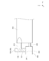
- FIG. 1 is a view showing the configuration of the shutter device according to the first embodiment.
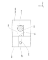
- FIG. 2 is a view showing the configuration of the shutter device according to the first embodiment.
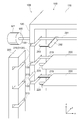
- FIG. 3 is a diagram for explaining the operation of the shutter device shown in FIG.
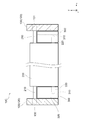
- FIG. 4 is a view showing the configuration of the shutter device according to the second embodiment.
- FIG. 5 is a view showing the configuration of the shutter device according to the second embodiment.
- FIG. 6 is a view showing the configuration of the shutter device according to the second embodiment.
- FIG. 7 is a view showing the configuration of the shutter device according to the third embodiment.
- FIG. 8 is a view showing the configuration of the shutter device according to the fourth embodiment.
- FIG. 9 is a view showing a configuration of a shutter device according to a first comparative example.
- FIG. 10 is a diagram showing a configuration of a shutter device according to a second comparative example.
- FIG. 11 is a view showing a configuration of a shutter device according to a third comparative example.
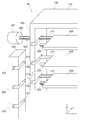
- the configuration of the shutter device 10 according to the first embodiment will be described with reference to FIGS. 1 to 3.
- the shutter device 10 is provided near the front grille of a vehicle (not shown), and is configured as a device for adjusting the flow rate of air flowing in from the front grille.
- the shutter device 10 includes a frame 100, fins 200, an actuator MT, and a link member 300.
- the frame 100 is a rectangular frame for rotatably supporting a fin 200 described later.
- the frame 100 has a top plate 110 and a pair of side plates 120.
- a bottom plate having substantially the same shape as the top plate 110 is also provided at the lower end portion of the frame 100, the illustration thereof is omitted.
- the top plate 110 is a rectangular plate material formed to extend in the left-right direction of FIG.
- a side plate 120 is provided so as to extend downward in FIG. 1 from each of both ends in the longitudinal direction of the top plate 110.
- the direction from left to right along the longitudinal direction of the top 110 is taken as the x direction, and the x axis is set along the same direction. Further, the direction from the lower side to the upper side along the longitudinal direction of the side plate 120 is taken as the z direction, and the z axis is set along the same direction. Furthermore, it is a direction perpendicular to any of the x direction and the z direction (also referred to as a direction perpendicular to the opening surface of the frame 100), and a direction from the near side to the far side in FIG. Y axis is set along the same direction.
- the x-axis, the y-axis, and the z-axis are set similarly in FIG.
- a plurality of support grooves 130 are formed in the side plate 120 provided on the ⁇ x direction side.
- Each of the support grooves 130 is a rectangular groove formed so as to retract from the end surface of the side plate 120 on the ⁇ y direction side along the y direction.
- the shapes of the respective support grooves 130 are identical to each other, and are arranged at equal intervals along the z direction.
- the support groove 130 is a groove for receiving the support protrusion 210 formed in the fin 200 described later inside.
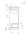
- FIG. 2 is a view schematically showing a state in which the shutter device 10 is cut along the xy plane and viewed from the z direction side.
- a plurality of through holes 131 are formed in the side plate 120 provided on the x direction side.
- Each through hole 131 is a circular through hole.
- the shapes of the through holes 131 are identical to each other, and are arranged at equal intervals along the z direction.
- the position in the z direction of each through hole 131 is the same as the position in the z direction of each support groove 130.
- the through hole 131 is a hole for inserting a support protrusion 210 formed in a fin 200 described later.
- the fins 200 are plate-like members rotatably supported by the frame 100, and a plurality of fins 200 are provided in the shutter device 10.
- the fins 200 are arranged along the z-direction, with the longitudinal direction along the x-axis.
- the fins 200 switch between a state in which the flow of air is blocked and a state in which the flow of air is not blocked by rotating around the rotation axis along the longitudinal direction.
- the fin 200 is provided with a pair of support protrusions 210 and drive protrusions 220.
- one of the support protrusions 210 is formed to extend from the end surface on the ⁇ x direction side of the fin 200 toward the ⁇ x direction side. Further, the other support projection 210 is formed to extend from the end surface of the fin 200 in the x direction toward the x direction.
- Each support projection 210 has a cylindrical shape, and their central axes coincide with each other.
- the shape of the support protrusion 210 may be a shape other than a cylindrical shape.
- the support protrusion 210 on the -x direction side is accommodated inside the support groove 130 formed in the side plate 120, and is thereby rotatably supported. Further, the support protrusions 210 on the x direction side are inserted into the through holes 131 formed in the side plate, and are also rotatably supported by this. Thus, the support projection 210 is a portion rotatably supported by the frame 100.
- the central axis of each support protrusion 210 is the rotation axis of the fin 200.
- the driving projection 220 is formed to extend from the end surface of the fin 200 in the ⁇ x direction toward the ⁇ x direction.
- the position where the driving protrusion 220 is formed is on the -y direction side of the position where the supporting protrusion 210 is formed.
- the drive projection 220 has a cylindrical shape similar to the support projection 210.
- the driving projection 220 is a portion for receiving a driving force from a link member 300 described later.
- the actuator MT is a rotating electrical machine that generates a driving force for rotating the frame 100.
- the support protrusions 210 of the fin 200 disposed closest to the z direction are longer than the support protrusions 210 of the other fins 200 and are connected to the drive shaft MS of the actuator MT. ing. Therefore, when the actuator MT is driven to rotate the drive shaft MS, the support protrusion 210 is also rotated.
- the fins 200 arranged closest to the z direction also function as members for directly receiving the driving force of the actuator MT.
- the driving force of the actuator MT is also transmitted to the other fins 200 by the link member 300 described next.
- the link member 300 is a member for transmitting the driving force of the actuator MT to the respective fins 200 and operating the respective fins 200 simultaneously. As shown in FIG. 2, the link member 300 is disposed between the side plate 120 on the ⁇ x direction side and the fin 200. Note that FIG. 1 shows the link member 300 removed from the above position in the ⁇ y direction.
- the link member 300 is formed with a plurality of drive grooves 310.
- Each drive groove 310 is a rectangular groove formed so as to retract from the end surface on the x direction side of the link member 330 along the ⁇ x direction.
- Each drive groove 310 is formed to extend along the y direction.
- the shapes of the respective driving grooves 310 are the same as one another, and are arranged at equal intervals along the z direction.
- a drive protrusion 220 formed on the fin 200 is accommodated inside the drive groove 310.
- the drive projection 220 is rotatably held by the link member 300.
- the drive protrusion 220 can also slide along the direction (y direction) in which the drive groove 310 extends.
- the driving groove 310 of the present embodiment is formed as a groove in which both ends along the y axis are open. Instead of such a mode, only the y-direction end of the drive groove 310 may be open, and the ⁇ y-direction end may be closed.
- the link member 300 is supported movably along the z-axis by a bearing (not shown).
- a bearing portion for example, a configuration in which a plurality of portions of the frame 100 are protruded toward the x direction side so as to sandwich the link member 300 from both the y direction side and the ⁇ direction side Conceivable.
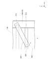
- FIG. 3 is a diagram schematically showing the fins 200, the link member 300, and the side plate 120 disposed on the ⁇ x direction side, as viewed from the x direction side.
- the actuator MT When the actuator MT is driven and the drive shaft MS rotates in the direction indicated by the arrow in FIG. 1, the fin 200 arranged closest to the z direction rotates in the same direction, and the drive projection 220 of the fin 200 is -z. Move to the side. By receiving a force from the drive protrusion 220, the link member 300 moves to the ⁇ z side.
- the fins 200 are fixed to the frame 100 by inserting the support protrusions 210 inside the support grooves 130 while moving the respective fins 200 in the y direction. It can be assembled. That is, the work of assembling the plurality of fins 200 can be completed from the ⁇ y direction side of the frame 100 without changing the posture of the members. For this reason, the operation cost of assembly can be reduced.
- the link member 300 when the link member 300 is attached to the shutter device 10, as shown by the arrow in FIG. 1, the link member 300 can be fitted while being moved in the y direction from the -y direction side of the frame 100. That is, both of the work of attaching the fins 200 to the frame 100 and the work of attaching the link member 300 to the frame 100 can be performed from the same direction. For this reason, the operation cost of assembly can be further reduced.
- the link member 300 also functions as the drop prevention member. That is, in the present embodiment, the link member 300 prevents the support projection 210 from coming off the support groove 130.
- reference numeral 320 denotes a portion of the link member 300 from the bottom surface of the drive groove 310 in the ⁇ x direction. The said part is also described below as “the groove bottom part 320.”
- the support protrusion 210 on the ⁇ x direction side is formed longer than the drive protrusion 220.
- the groove bottom portion 320 is disposed at a position closer to the ⁇ y direction side with respect to a portion of the support protrusion 210 that protrudes to the ⁇ x direction side with respect to the drive protrusion 220. Therefore, when the support projection 210 moves in a direction (-y direction) to be removed from the support groove 130, the above-mentioned portion of the support projection 210 (a portion which protrudes to the -x direction side with respect to the drive projection 220) Will hit the groove bottom 320. Thus, the support projection 210 is prevented from coming off the support groove 130.
- FIG. 9 shows a shutter device 10D according to a first comparative example.
- the driving protrusion 220 is provided on the end surface of the fin 200 on the x direction side.
- the driving projection 220 is inserted into the through hole 351 of the link member 350.
- the link member 350 is a plate-like member provided so as to extend along the z-axis.
- a plurality of the through holes 351 are formed in the drive projection 220 so as to be aligned along the z-axis.
- the link member 350 transmits the driving force of the actuator MT to the respective fins 200, and the respective fins 200 operate simultaneously.
- the support protrusion 210 is accommodated inside the support groove 130 of the frame 100, as in the first embodiment (FIG. 2) described above. It is prevented by the dropout preventing member 500 in this comparative example that the support projection 210 is disengaged from the support groove 130.
- the falling prevention member 500 is a member fixed to the side plate 120 of the frame 100. A part of the fall prevention member 500 is inserted between the side plate 120 and the fin 200 and extends to a position close to the support protrusion 210.
- the support protrusion 210 moves in a direction ( ⁇ y direction) in which the support protrusion 210 is disengaged from the support groove 130, the support protrusion 210 will abut the drop preventing member 500. Thus, the support projection 210 is prevented from coming off the support groove 130.
- the drop-off preventing member 500 is provided separately from the link member 350, the number of parts is larger than that in the first embodiment. Further, in order to assemble the link member 350 on the driving projection 220 of the fin 200, it is necessary to move the link member 350 from the x direction side toward the ⁇ x direction side. In such a configuration, both of the work of assembling the fins 200 to the frame 100 and the work of assembling the link member 300 to the frame 100 can not be performed from the same direction, and therefore, compared to the first embodiment. Work cost will rise. As apparent from the comparison with the first comparative example, in the shutter device 10 according to the present embodiment, in addition to not increasing the number of parts as in the comparative example, the work of assembling the fin 200 becomes easy. Production costs are curtailed.
- the link member 350 performs an amplitude movement along the y axis along with the opening and closing operation of the fin 200. As a result, there is a possibility that the drive projection 220 may come out of the through hole 351.
- a configuration example for preventing this will be described with reference to FIG. 10 and FIG.
- FIG. 10 shows a shutter device 10E according to a second comparative example.
- a protrusion 221 for retaining is formed in the vicinity of the tip end of the driving protrusion 220.
- the protrusion 221 is in a state of protruding from the side surface of the drive protrusion 220.
- the protrusion 221 is elastically deformed and is retracted inside the drive projection 220.
- the projection 221 is in a state of protruding again from the side surface of the drive projection 220.
- the protrusion 221 prevents the drive projection 220 from coming off from the through hole 351.
- FIG. 11 shows a shutter device 10F according to a third comparative example.
- a detachment preventing member ST which is a cylindrical member, is attached to the tip of the driving projection 220.
- the detachment preventing member ST is attached and fixed to the tip of the driving projection 220.
- the diameter of the removal prevention member ST of the drive projection 220 is larger than the inner diameter of the through hole 351.
- the detachment prevention member ST prevents the drive projection 220 from coming out of the through hole 351.
- the same number of slip preventing members ST as the fins 200 are required, and an operation of attaching all the slip preventing members ST to the tip of the driving projection 220 is required. . For this reason, there is a problem that the number of parts and the number of operation steps are significantly increased.
- the shutter device 10 since it is sufficient to dispose the drive projection 220 inside the drive groove 310 of the link member 300, as in the second comparative example, the fin 200 is used. There is no problem of increasing the required load when assembling the. Further, since it is not necessary to attach another member to the drive projection 220, there is no problem that the number of parts and the number of operation steps are significantly increased as in the third comparative example.
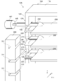
- the configuration of the shutter device 10A according to the second embodiment will be described with reference to FIGS. In the following, differences from the first embodiment will be mainly described, and descriptions of points in common with the first embodiment will be omitted as appropriate.
- the support protrusion 210 is thicker than the drive protrusion 220.
- the groove width (width along the z-axis) of the support groove 130 for receiving the support projection 210 is also larger than that in the first embodiment.
- FIG. 5 is a view schematically showing a state where the shutter device 10A is cut along the xy plane and viewed from the z direction side.
- the tip on the ⁇ y direction side of the fin 200 in the present embodiment protrudes further to the ⁇ y direction side than the tip on the ⁇ y direction side of the side plate 120.
- the length of the drive projection 220 is substantially the same as the length of the support projection 210.
- the link member 300 in the present embodiment is disposed at a position closer to the -y direction than the side plate 120, and is movable along the z-axis while in contact with the side plate 120. As shown in FIG. 5, the bottom surface 311 of the drive groove 310 is located on the same plane as the surface 121 of the side plate 120 on the ⁇ x direction side.
- FIG. 6 is a view schematically depicting the link member 300 and the side plate 120 disposed on the ⁇ x direction side, as viewed from the x direction.
- the groove width W1 (width along the z-axis) of the drive groove 310 is smaller than the thickness (diameter D1) of the support protrusion 210.
- the drive shaft MS of the actuator MT is connected to the drive shaft 291 instead of being connected to the support protrusion 210 of the fin 200.
- the drive shaft 291 is a cylindrical member, and its diameter is the same as the diameter of the support protrusion 210.
- the drive shaft 291 is in a state in which its central axis is aligned with the x axis, and is accommodated inside the support groove 130 in the same manner as the support protrusion 210.
- connection plate 292 is provided on a portion of the drive shaft 291 located on the x direction side of the side plate 120.
- the connection plate 292 is a plate-like member formed to extend in a direction perpendicular to the central axis of the drive shaft 291.
- a connection protrusion 293 is provided in the vicinity of the tip end portion of the connection plate 292.
- connection projection 293 is a cylindrical member, and is formed to extend from the connection plate 292 in the ⁇ x direction.
- the diameter of the connection protrusion 293 is the same as the diameter of the drive protrusion 220.
- the x-coordinate of the tip of the connection protrusion 293 is the same as the x-coordinate of the tip of the drive protrusion 220.
- connection projection 293 is accommodated inside the drive groove 310 (that is, the groove extending along the y direction) formed on the most z side among the plurality of drive grooves 310 formed in the link member 300.
- the driving groove 310 is also referred to as “connection groove 310A”.
- the shape of the connection protrusion 293 may be different from the shape of the drive protrusion 220.
- the shape of the connection groove 310A may be different from the shape of the other connection grooves 310 so as to support the connection protrusion 293.
- the link member 300 moves in the z direction, and the respective fins 200 rotate in the opposite direction to the above.
- the driving force of the actuator MT is transmitted to the drive projections 220 of all the fins 200 by the link member 300 in this embodiment, and operates all the fins 200 simultaneously.
- the drive shaft 291 functions to transmit the driving force from the actuator MT to the link member 300.
- the connection projection 293 provided on the drive shaft 291 is a portion connected to the connection groove 310A of the link member 300.
- the driving force from the actuator MT is not directly transmitted to the fin 200 as in the present embodiment, but is indirectly transmitted via another member. Has the same effect as the one.
- the driving protrusion 220 is also formed on the x-direction side portion of the fin 200. Further, a link member 300 having the same shape as that on the ⁇ x direction side is also arranged at a position on the fin 200 in the x direction side. Inside the drive groove 310 formed in the link member 300, the drive protrusion 220 on the x direction side is accommodated.
- the fins 200 and the indication structure thereof are symmetrical with respect to the yz plane.
- the work of assembling the plurality of fins 200 and the link member 300 is completed only by moving each member linearly from the -y direction side of the frame 100 toward the y direction. It can be done. For this reason, the operation cost of assembly can be further reduced.
Landscapes
- Engineering & Computer Science (AREA)
- Chemical & Material Sciences (AREA)
- Combustion & Propulsion (AREA)
- Transportation (AREA)
- Mechanical Engineering (AREA)
- Cooling, Air Intake And Gas Exhaust, And Fuel Tank Arrangements In Propulsion Units (AREA)
- Air-Flow Control Members (AREA)
- Air-Conditioning For Vehicles (AREA)
Priority Applications (3)
| Application Number | Priority Date | Filing Date | Title |
|---|---|---|---|
| CN201880049867.2A CN110997384B (zh) | 2017-07-25 | 2018-06-08 | 风门装置 |
| DE112018003809.2T DE112018003809B4 (de) | 2017-07-25 | 2018-06-08 | Verschlussvorrichtung |
| US16/736,106 US10981444B2 (en) | 2017-07-25 | 2020-01-07 | Shutter device |
Applications Claiming Priority (2)
| Application Number | Priority Date | Filing Date | Title |
|---|---|---|---|
| JP2017-143595 | 2017-07-25 | ||
| JP2017143595A JP6756313B2 (ja) | 2017-07-25 | 2017-07-25 | シャッター装置 |
Related Child Applications (1)
| Application Number | Title | Priority Date | Filing Date |
|---|---|---|---|
| US16/736,106 Continuation US10981444B2 (en) | 2017-07-25 | 2020-01-07 | Shutter device |
Publications (1)
| Publication Number | Publication Date |
|---|---|
| WO2019021650A1 true WO2019021650A1 (ja) | 2019-01-31 |
Family
ID=65039546
Family Applications (1)
| Application Number | Title | Priority Date | Filing Date |
|---|---|---|---|
| PCT/JP2018/022085 Ceased WO2019021650A1 (ja) | 2017-07-25 | 2018-06-08 | シャッター装置 |
Country Status (5)
| Country | Link |
|---|---|
| US (1) | US10981444B2 (https=) |
| JP (1) | JP6756313B2 (https=) |
| CN (1) | CN110997384B (https=) |
| DE (1) | DE112018003809B4 (https=) |
| WO (1) | WO2019021650A1 (https=) |
Families Citing this family (1)
| Publication number | Priority date | Publication date | Assignee | Title |
|---|---|---|---|---|
| JP7358820B2 (ja) * | 2019-07-26 | 2023-10-11 | 株式会社デンソー | 車両のシャッタ装置 |
Citations (4)
| Publication number | Priority date | Publication date | Assignee | Title |
|---|---|---|---|---|
| US20110251761A1 (en) * | 2010-04-13 | 2011-10-13 | Charnesky Scott P | Shutter with offset louver pivot |
| US20150330288A1 (en) * | 2014-05-13 | 2015-11-19 | Hyundai Motor Company | Apparatus for controlling air flow to engine room of vehicle and air flow control system including the same |
| JP2015217827A (ja) * | 2014-05-19 | 2015-12-07 | シロキ工業株式会社 | 車両用シャッター装置 |
| KR101575255B1 (ko) * | 2014-05-27 | 2015-12-07 | 현대자동차 주식회사 | 차량용 액티브 에어 플랩 |
Family Cites Families (25)
| Publication number | Priority date | Publication date | Assignee | Title |
|---|---|---|---|---|
| US3759054A (en) * | 1972-07-03 | 1973-09-18 | Kysor Industrial Corp | Split shutter control system |
| JPS6126586Y2 (https=) * | 1980-11-21 | 1986-08-09 | ||
| JPS5815127B2 (ja) | 1980-11-25 | 1983-03-24 | 名東工業株式会社 | ゆでめん機 |
| JP4678498B2 (ja) * | 2005-06-27 | 2011-04-27 | アイシン精機株式会社 | 可動グリルシャッタ装置 |
| JP4678500B2 (ja) * | 2005-06-28 | 2011-04-27 | アイシン精機株式会社 | 車両用可動グリルシャッタ装置 |
| JP2008106982A (ja) * | 2006-10-25 | 2008-05-08 | Calsonic Kansei Corp | 車両用熱交換器のシャッター構造 |
| JP2008260447A (ja) * | 2007-04-13 | 2008-10-30 | Mikuni Corp | ラジエータシャッター |
| KR101033792B1 (ko) * | 2009-08-27 | 2011-05-13 | 현대자동차주식회사 | 고장대응을 위한 자동차용 에어플랩 개폐장치 |
| JP5573268B2 (ja) | 2010-03-19 | 2014-08-20 | アイシン精機株式会社 | 車両用可動グリルシャッター |
| JP2011201439A (ja) * | 2010-03-25 | 2011-10-13 | Aisin Seiki Co Ltd | 車両用可動グリルシャッター |
| US8646552B2 (en) * | 2010-07-21 | 2014-02-11 | Shape Corp. | Integrated energy absorber and air flow management structure |
| FR2978087B1 (fr) * | 2011-07-21 | 2013-08-23 | Valeo Systemes Thermiques | Dispositif d'obturation d'orifice de face avant de vehicule automobile. |
| JP5678832B2 (ja) * | 2011-07-27 | 2015-03-04 | 豊田合成株式会社 | グリルシャッタ装置 |
| CH706456B1 (de) * | 2012-04-30 | 2016-03-15 | Schwanden Kunststoff | Jalousie für die Anordnung vor einem Kühler. |
| US9694669B2 (en) * | 2012-08-31 | 2017-07-04 | Magna International Inc. | Active grille multi part modular frame |
| KR101964599B1 (ko) * | 2012-10-18 | 2019-04-02 | 현대모비스 주식회사 | 차량용 에어 플랩 장치 |
| FR2997348B1 (fr) * | 2012-10-25 | 2016-07-01 | Valeo Systemes Thermiques | Volet d'obturation de ventilation pour automobile a faible signature aeraulique |
| US9533565B2 (en) * | 2013-02-05 | 2017-01-03 | Montaplast of North America, Inc. | Active grille shutter assembly |
| JP5915582B2 (ja) * | 2013-03-29 | 2016-05-11 | マツダ株式会社 | 車両のグリルシャッタ構造 |
| JP6241220B2 (ja) * | 2013-11-14 | 2017-12-06 | アイシン精機株式会社 | グリルシャッタ装置及びその製造方法 |
| US9902256B2 (en) * | 2014-05-19 | 2018-02-27 | Shiroki Corporation | Vehicular shutter device |
| GB2520626A (en) * | 2014-10-21 | 2015-05-27 | Daimler Ag | Grille for a vehicle, in particular a commercial vehicle, as well as a vehicle |
| JP2016135636A (ja) * | 2015-01-23 | 2016-07-28 | シロキ工業株式会社 | 車両用シャッター装置 |
| JP6640586B2 (ja) | 2016-02-08 | 2020-02-05 | 株式会社ミツバ | ブラシレスモータ |
| US10525819B2 (en) * | 2016-08-12 | 2020-01-07 | Magna Exteriors Inc. | Active grille, scalable design |
-
2017
- 2017-07-25 JP JP2017143595A patent/JP6756313B2/ja active Active
-
2018
- 2018-06-08 WO PCT/JP2018/022085 patent/WO2019021650A1/ja not_active Ceased
- 2018-06-08 DE DE112018003809.2T patent/DE112018003809B4/de active Active
- 2018-06-08 CN CN201880049867.2A patent/CN110997384B/zh active Active
-
2020
- 2020-01-07 US US16/736,106 patent/US10981444B2/en active Active
Patent Citations (4)
| Publication number | Priority date | Publication date | Assignee | Title |
|---|---|---|---|---|
| US20110251761A1 (en) * | 2010-04-13 | 2011-10-13 | Charnesky Scott P | Shutter with offset louver pivot |
| US20150330288A1 (en) * | 2014-05-13 | 2015-11-19 | Hyundai Motor Company | Apparatus for controlling air flow to engine room of vehicle and air flow control system including the same |
| JP2015217827A (ja) * | 2014-05-19 | 2015-12-07 | シロキ工業株式会社 | 車両用シャッター装置 |
| KR101575255B1 (ko) * | 2014-05-27 | 2015-12-07 | 현대자동차 주식회사 | 차량용 액티브 에어 플랩 |
Also Published As
| Publication number | Publication date |
|---|---|
| DE112018003809T5 (de) | 2020-04-30 |
| JP2019025930A (ja) | 2019-02-21 |
| JP6756313B2 (ja) | 2020-09-16 |
| DE112018003809B4 (de) | 2026-01-22 |
| US20200139806A1 (en) | 2020-05-07 |
| US10981444B2 (en) | 2021-04-20 |
| CN110997384A (zh) | 2020-04-10 |
| CN110997384B (zh) | 2023-03-28 |
Similar Documents
| Publication | Publication Date | Title |
|---|---|---|
| JP5853801B2 (ja) | グリルシャッタ装置 | |
| KR101272930B1 (ko) | 차량용 액티브 에어플랩 장치 | |
| JP6189194B2 (ja) | グリルシャッター装置 | |
| US20130252531A1 (en) | Grill shutter device | |
| KR101542962B1 (ko) | 차량용 액티브 에어 플랩 | |
| US12409724B2 (en) | Air flap having mixed-type door structure | |
| JP2016055718A (ja) | グリルシャッター | |
| CN108068611B (zh) | 能够在故障期间打开或关闭的车辆的活动风门组件 | |
| KR20150071262A (ko) | 액티브 에어 플랩 | |
| WO2016059766A1 (ja) | 車両用熱交換器のシャッター構造 | |
| WO2019021650A1 (ja) | シャッター装置 | |
| JP2016055719A (ja) | グリルシャッター | |
| WO2021019954A1 (ja) | シャッター装置 | |
| KR101595979B1 (ko) | 액티브 에어 플랩 | |
| US20200324641A1 (en) | Shutter device and method for manufacturing shutter device | |
| JP2016130038A (ja) | レジスタ用操作ノブ | |
| KR20150062322A (ko) | 차량의 액티브 에어 플랩 | |
| JP5284497B2 (ja) | 空調装置 | |
| JP6981209B2 (ja) | ハーネスユニット | |
| KR20150070770A (ko) | 액티브 에어 플랩 | |
| KR200480868Y1 (ko) | 배선용 차단기 | |
| WO2020022057A1 (ja) | 組立体 | |
| WO2021019952A1 (ja) | シャッター装置 | |
| WO2021060112A1 (ja) | 車両のシャッタ装置 | |
| JP2023019691A (ja) | シャッター装置 |
Legal Events
| Date | Code | Title | Description |
|---|---|---|---|
| 121 | Ep: the epo has been informed by wipo that ep was designated in this application |
Ref document number: 18838659 Country of ref document: EP Kind code of ref document: A1 |
|
| WWE | Wipo information: entry into national phase |
Ref document number: 112018003809 Country of ref document: DE |
|
| WWP | Wipo information: published in national office |
Ref document number: 112018003809 Country of ref document: DE |
|
| 122 | Ep: pct application non-entry in european phase |
Ref document number: 18838659 Country of ref document: EP Kind code of ref document: A1 |
|
| WWG | Wipo information: grant in national office |
Ref document number: 112018003809 Country of ref document: DE |