WO2018199073A1 - ロボットシステム及びそれを備える作業ライン - Google Patents
ロボットシステム及びそれを備える作業ライン Download PDFInfo
- Publication number
- WO2018199073A1 WO2018199073A1 PCT/JP2018/016567 JP2018016567W WO2018199073A1 WO 2018199073 A1 WO2018199073 A1 WO 2018199073A1 JP 2018016567 W JP2018016567 W JP 2018016567W WO 2018199073 A1 WO2018199073 A1 WO 2018199073A1
- Authority
- WO
- WIPO (PCT)
- Prior art keywords
- work
- robot
- workpiece
- robot system
- locator
- Prior art date
- Legal status (The legal status is an assumption and is not a legal conclusion. Google has not performed a legal analysis and makes no representation as to the accuracy of the status listed.)
- Ceased
Links
Images



Classifications
-
- B—PERFORMING OPERATIONS; TRANSPORTING
- B62—LAND VEHICLES FOR TRAVELLING OTHERWISE THAN ON RAILS
- B62D—MOTOR VEHICLES; TRAILERS
- B62D65/00—Designing, manufacturing, e.g. assembling, facilitating disassembly, or structurally modifying motor vehicles or trailers, not otherwise provided for
- B62D65/02—Joining sub-units or components to, or positioning sub-units or components with respect to, body shell or other sub-units or components
- B62D65/022—Transferring or handling sub-units or components, e.g. in work stations or between workstations and transportation systems
-
- B—PERFORMING OPERATIONS; TRANSPORTING
- B23—MACHINE TOOLS; METAL-WORKING NOT OTHERWISE PROVIDED FOR
- B23P—METAL-WORKING NOT OTHERWISE PROVIDED FOR; COMBINED OPERATIONS; UNIVERSAL MACHINE TOOLS
- B23P21/00—Machines for assembling a multiplicity of different parts to compose units, with or without preceding or subsequent working of such parts, e.g. with program control
- B23P21/004—Machines for assembling a multiplicity of different parts to compose units, with or without preceding or subsequent working of such parts, e.g. with program control the units passing two or more work-stations whilst being composed
-
- B—PERFORMING OPERATIONS; TRANSPORTING
- B62—LAND VEHICLES FOR TRAVELLING OTHERWISE THAN ON RAILS
- B62D—MOTOR VEHICLES; TRAILERS
- B62D65/00—Designing, manufacturing, e.g. assembling, facilitating disassembly, or structurally modifying motor vehicles or trailers, not otherwise provided for
- B62D65/005—Inspection and final control devices
-
- B—PERFORMING OPERATIONS; TRANSPORTING
- B62—LAND VEHICLES FOR TRAVELLING OTHERWISE THAN ON RAILS
- B62D—MOTOR VEHICLES; TRAILERS
- B62D65/00—Designing, manufacturing, e.g. assembling, facilitating disassembly, or structurally modifying motor vehicles or trailers, not otherwise provided for
- B62D65/02—Joining sub-units or components to, or positioning sub-units or components with respect to, body shell or other sub-units or components
- B62D65/18—Transportation, conveyor or haulage systems specially adapted for motor vehicle or trailer assembly lines
Definitions
- the present invention relates to a robot system that performs work on a work such as a car body of an automobile and a work line including the same.
- a work line such as an automobile body assembly line has been provided with a plurality of work stages along the line, and the work is transported between the work stages by a transport device.
- Each work stage is provided with a locator for positioning the transferred workpiece, and various operations such as welding and painting by a robot are performed on the workpiece positioned on the locator.
- Patent Document 1 discloses a vehicle body assembly line that includes a plurality of welding stages and conveys a vehicle body as a workpiece between the welding stages by a skid.
- a positioning device having a locating pin at the tip and one or more welding robots are disposed on the welding stage of the vehicle body assembly line.
- the vehicle body transported to the assembly work stage by the skid is positioned while being lifted up to a predetermined level from the skid by the locator.
- spot welding is performed on the positioned vehicle body by the welding robot.
- the workpiece generally has a plurality of work points (for example, a plurality of joint points to be spot welded) to be worked by the robot.
- the robot can work only on a work location located within the movable range of the robot among a plurality of work locations of the workpiece. Also, even when the work location is within the movable range, depending on the shape of the work, etc., when a part of the work placed between the robot and the work location cannot act due to the robot's barrier There is also.
- work places where one robot can perform work are limited, and in order to complete work for all work places, it is necessary to install a large number of robots corresponding to the positions of the work places. there were. However, for example, from the viewpoint of installation space, cost, and the like, a work line that can complete work with as few robots as possible may be desired.
- an object of the present invention is to provide a robot system capable of completing work on a work having a plurality of work points with fewer robots and a work line including the robot system.
- a robot system is a robot system that has a plurality of holes and performs work on a workpiece having a plurality of work locations, and at least first and second of the plurality of work locations. And at least one robot that performs a predetermined operation on the work location, and a locating pin that is movable in three axial directions orthogonal to each other, and the workpiece in which the locating pin is inserted into the hole is
- a plurality of locators that are positioned at a first position where the first work location is operated; and a control device that controls the operation of the plurality of locators, wherein the control device is configured to control the first work location with respect to the first work location.
- the position of the workpiece is changed to the first position while maintaining the state where the locate pin is inserted into the hole.
- Placed al controls the plurality of locator to change to the second position where the second working position is the work by the robot.
- a locator makes the position of a workpiece
- the locator includes a first moving module that moves the locating pin in a first horizontal direction, and a second moving module that moves the locating pin in a second horizontal direction orthogonal to the first horizontal direction. And a third moving module for moving the locate pin in the vertical direction, wherein the control device changes the position of the workpiece from the first position to the second position. , At least one of the second moving module and the third moving module may be controlled.
- the plurality of locators change the position of the workpiece from the first position to the second position, so that the second work location is out of the movable range of the robot. To move within the movable range of the robot.
- the plurality of locators change the position of the workpiece from the first position to the second position, so that the second work location is caused by interference with the workpiece.
- the robot moves from a position where it cannot work using the robot to a position where the robot can work without interfering with the workpiece.
- the plurality of locators include a rotation mechanism that rotates the locating pin around a predetermined axis extending in a horizontal direction, and the control device moves the position of the workpiece from the first position to the first position.
- the rotating mechanism may be controlled to incline the workpiece.
- the workpiece is a part of a vehicle body or a part of a vehicle body having a plurality of joints as the plurality of work points, and the robot includes the first and second parts. It is a robot which joins to the work part.
- the work line according to one aspect of the present invention is a work line provided with a plurality of work stages in which a predetermined work is performed on the work along a work transport path, and the work is Between any one of the robot systems described above, having the first and second work locations and disposed on at least one of the plurality of work stages, and between two work stages adjacent to each other of the plurality of work stages A conveying device for conveying the workpiece.
- FIG. 1 is a perspective view of a robot system according to a first embodiment. It is the schematic side view which looked at the robot system which concerns on 1st Embodiment from the conveyance direction downstream of the workpiece
- FIG. 4B is a schematic plan view of the robot system shown in FIG. 4A.
- FIG. 5B is a schematic plan view of the robot system shown in FIG. 5A. It is a figure for demonstrating the operation example of the robot system which concerns on 1st Embodiment, and is a schematic side view of the robot system which positioned the workpiece
- FIG. 6B is a schematic plan view of the robot system shown in FIG. 6A.
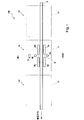
- FIG. 1 is a schematic plan view of a work line 100 according to the first embodiment.
- the work line 100 according to the present embodiment is a work transport system that performs work on a work while transporting the work.
- parts such as a frame constituting a body of the vehicle body or a part of the body conveyed in the work line 100 are referred to as a workpiece W.
- the work W is described as being transported from the right side to the left side in FIG. 1.
- the lower side in FIG. 1 is the front side and the upper side in FIG. 1 is the back side. To do.
- the work line 100 is provided with a plurality of work stages (work areas) S, S ′, S ′′ on which a predetermined work is performed on the work W along the transport path of the work W.
- Robot systems 1A, 1A ', and 1A "that perform work on the workpiece W are arranged on the work stages S, S', and S", respectively.
- the work W is provided with many joints to be joined, and the robot systems 1A, 1A ′, 1A ′′ perform joining work on the joints of the work W.
- the robot systems 1A, 1A ′, 1A ′′ may perform different types of work on the workpiece W.
- three work stages S, S ′, and S ′′ are shown, but the number of work stages provided in the work line 100 may be one, two, or four or more.
- the work line 100 is provided with a transport device 2 that transports the workpiece W in the transport direction between two work stages adjacent to each other.
- the transport device 2 is, for example, a conveyor.
- the configuration of the transport device 2 is not particularly limited.
- the transport device 2 may be configured to suspend and transport the workpiece W, or may be a cart type that can move in the transport direction.
- One transfer device 2 may be provided for two work stages adjacent to each other, or one transfer device 2 may be provided for the entire work line 100.
- the robot system 1A ′ performs a joining operation on a plurality of predetermined joining locations of the workpiece W.
- the work W is transferred to the next work stage S by the transfer device 2.
- the robot system 1A performs the joining work on a plurality of joints different from the parts joined on the work stage S ′.
- the work W is then transported to the next work stage S '' by the transport device 2.
- the robot system 1A ′′ performs a joining operation on a plurality of joints different from the parts joined on the work stages S ′ and S. In this way, while the workpieces W are conveyed on the work line 100, operations are successively performed on a large number of joints of the workpiece W.
- a robot system 1A disposed on the work stage S will be described as an example of a robot system provided in the work line 100.
- the robot system 1A includes two robot arms 4a and 4b and a control device 5 that controls these operations.
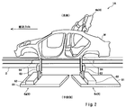
- FIG. 2 is a perspective view of the robot system 1A disposed on the work stage S.
- FIG. 3 is a schematic side view of the robot system 1A as viewed from the downstream side in the conveyance direction of the workpiece W.
- elements included in the other robot systems 1A ′ and 1A ′′ are omitted in FIG. 1, and the robot arm 4a on the near side is omitted in FIG.
- two robot arms 4 a and 4 b are arranged on both sides (that is, the front side and the back side) with the conveyance path of the workpiece W interposed therebetween.
- the end effector 47 is attached to the tip of each robot arm 4a, 4b.
- the robot arm 4a or 4b, the end effector 47 attached to the robot arm 4a or 4b, and the control device 5 that controls the operation of the robot arm 4 and the end effector 47 constitute one robot 3 that performs a joining operation on the workpiece W.
- the robot 3 is equipped with a spot welding gun as an end effector 47 at the tip of each robot arm 4a, 4b so that a spot welding operation can be performed as a joining operation.
- the joining operation performed by the robot 3 is not limited to spot welding, and may be, for example, friction stir welding, rivet joining, arc welding, joining using screws, bolts, nuts, or the like.
- the robot arms 4a and 4b have the same configuration as each other, hereinafter, the robot arms 4a and 4b will be collectively referred to, and the robot arm selected arbitrarily from among the robot arms 4a and 4b will be described. , And the robot letter 4 is omitted.
- the robot arm 4 is an articulated robot arm having three or more joints JT1 to JT6, and a plurality of links 41 to 46 are sequentially connected. More specifically, in the first joint JT1, the base 48 and the base end portion of the first link 41 are coupled so as to be rotatable about an axis extending in the vertical direction. In the second joint JT2, the distal end portion of the first link 41 and the proximal end portion of the second link 42 are coupled so as to be rotatable about an axis extending in the horizontal direction. In the third joint JT3, the distal end portion of the second link 42 and the proximal end portion of the third link 43 are coupled so as to be rotatable about an axis extending in the horizontal direction.
- the distal end portion of the third link 43 and the proximal end portion of the fourth link 44 are coupled so as to be rotatable about an axis extending in the longitudinal direction of the fourth link 43.
- the distal end portion of the fourth link 44 and the proximal end portion of the fifth link 45 are coupled so as to be rotatable about an axis orthogonal to the longitudinal direction of the link 44.
- the distal end portion of the fifth link 45 and the proximal end portion of the sixth link 46 are coupled to be able to rotate.
- a mechanical interface is provided at the tip of the sixth link 46.
- An end effector 47 is detachably attached to this mechanical interface.
- the joints JT1 to JT6 are provided with a drive motor (not shown) as an example of an actuator that relatively rotates two members connected to each other.
- the drive motor is, for example, a servo motor that is servo-controlled by the control device 5.
- the joints JT1 to JT6 are provided with a rotation sensor for detecting the rotational position of the drive motor and a current sensor (none of which is shown) for detecting a current for controlling the rotation of the drive motor. Yes.
- the rotation sensor is, for example, an encoder.
- the control device 5 includes, for example, a calculation unit (not shown) including a microcontroller, an MPU, a PLC (Programmable Logic Controller), a logic circuit, and a memory unit (not shown) including a ROM, a RAM, and the like. ing.
- a calculation unit including a microcontroller, an MPU, a PLC (Programmable Logic Controller), a logic circuit, and a memory unit (not shown) including a ROM, a RAM, and the like. ing.
- the robot system 1A includes four locators 6a, 6b, 6c, and 6d.
- Locators 6a, 6b, 6c, 6d cooperate with each other to position workpiece W.
- the locator 6a and the locator 6b are arranged to face both sides (that is, the near side and the far side), respectively, across the conveyance path of the workpiece W.
- the locator 6c and the locator 6d are arranged opposite to both sides (that is, the front side and the back side) with the conveyance path of the workpiece W sandwiched between the locator 6a and the locator 6b on the upstream side in the conveyance direction.
- the robot arm 4a is disposed on the front side of the locators 6a and 6c between the locator 6a and the locator 6c in the transport direction. Further, the robot arm 4b is disposed behind the locators 6b and 6d between the locator 6b and the locator 6d in the transport direction.
- locators 6a, 6b, 6c, and 6d have the same configuration, locators 6a, 6b, 6c, and 6d are collectively referred to below, and arbitrarily selected from locators 6a, 6b, 6c, and 6d When describing the locator, the locator 6 is omitted by omitting the alphabetical characters.
- the locator 6 supports the work W transferred to the work stage S by the transfer device 2 in cooperation with each other and positions the work W at a predetermined position where the robot 3 can work. As shown in FIG. 3, the locator 6 has a locating pin 64 inserted through a hole h formed at the bottom of the workpiece W.
- the locator 6 includes a first moving module 61, a second moving module 62, and a third moving module 63 so that the locating pin 64 can be moved in three axial directions orthogonal to each other, and in this order from bottom to top. Concatenated and configured.
- the first moving module 61 moves the locate pin 64 in a first horizontal direction parallel to the workpiece W conveyance direction.
- the first moving module 61 includes a first base member extending in the first horizontal direction, and a first slide member that is slidably driven in the first horizontal direction with respect to the first base member.
- the first base member of the first moving module 61 is fixed on a fixed base (not shown).
- the second moving module 62 moves the locate pin 64 in a second horizontal direction orthogonal to the transport direction.
- the second moving module 62 includes a second base member extending in the second horizontal direction, and a second slide member that is slidably driven in the second horizontal direction with respect to the second base member.
- the second base member of the second movement module 62 is fixed on the first slide member of the first movement module 61.
- the third moving module 63 moves the locate pin 64 in the vertical direction.
- the third moving module 63 includes a third base member extending in the vertical direction and a third slide member that is slidably driven in the vertical direction with respect to the third base member.
- the third base member of the third movement module 63 is erected on the second slide member of the second movement module 62.
- a locate pin 64 is fixed vertically upward on the third slide member.
- Locator 6 supports work W by inserting locating pin 64 through hole h of work W.
- a support surface that abuts around the hole h of the workpiece W may be provided around the locate pin 64. Further, the locate pin 64 may have a function of clamping the workpiece W after being inserted into the hole h of the workpiece W.
- the locator 6 includes a first moving module 61, a second moving module 62, and a third moving module 63 arranged in this order from the bottom to the top.
- the arrangement of the second moving module 62 and the third moving module 63 is not particularly limited.
- the hole h through which the locate pin 64 is inserted may not be provided at the bottom of the work W, and may be provided, for example, on the side of the work W. In this case, the locate pin 64 may be arranged to face the horizontal direction.
- the first moving module 61, the second moving module 62, and the third moving module 63 each include a drive motor (not shown) for slidingly driving the first slide member, the second slide member, and the third slide member.
- the control device 5 controls not only the robot arm 4 but also the operation of the locator 6. That is, the control device 5 can arbitrarily change the position of the locate pin 64 by operating each drive motor provided in the first moving module 61, the second moving module 62, and the third moving module 63.
- the robot arm 4 and the locator 6 may be controlled by separate control devices.
- FIG. 4A is a schematic side view of the robot system 1A immediately after the work W is transferred to the work stage S.
- the robot arm 4 is omitted in FIG. 4A.
- the locator 6 is in a state where the locating pin 64 is retracted downward so as not to contact the work W being transported.
- the transport device 2 transports the workpiece W to a predetermined position where the locate pin 64 and the hole h inserted therethrough coincide with the vertical direction.
- FIG. 4B is a schematic plan view of the robot system 1A shown in FIG. 4A.
- the movable ranges Ra and Rb of the robot arms 4a and 4b are shown surrounded by two-dot chain lines, respectively.
- the movable ranges Ra and Rb are the maximum ranges in which each part (including the end effector 47) of the robot arms 4a and 4b can move structurally.
- the stopper is excluded.
- the workpiece W transferred to the work stage S is first positioned to the first position by the locator 6, and then positioned to a second position different from the first position.
- the Of the plurality of joints of the work W the part joined by the robot arm 4 when the work W is at the first position is referred to as a first joint (first work part).
- the part joined by the robot arm 4 when the workpiece W is in the second position is referred to as a second joint (second work part).
- first joint first work part
- second joint second work part
- FIG. 5A is a schematic side view of the robot system 1A in which the workpiece W is positioned at the first position.
- the locator 6 drives the third moving module 63 to insert the locating pin 64 into the hole h of the workpiece W, as shown in FIG. 5A.
- the work W is supported as described above.
- the locator 6 positions the position of the workpiece W to the first position set in advance.
- FIG. 5B is a schematic plan view of the robot system 1A shown in FIG. 5A.
- the robot arm 4 performs a joining operation on the first joining location among the plurality of joining locations of the workpiece W.
- the first joint location is within one of the movable ranges Ra and Rb of the robot arms 4a and 4b. In the present embodiment, the first joint location is in the area A hatched in FIG. 5B.
- FIG. 6A is a schematic side view of the robot system 1A in which the workpiece W is positioned at the second position.
- the locator 6 keeps the position of the workpiece W while maintaining the state where the locating pin 64 is inserted into the hole h. Change from the first position to the second position.
- the locator 6 drives the first moving module 61 and moves the locating pin 64 in the transport direction (ie, the first direction). The position of the workpiece W is changed to a preset second position.
- FIG. 6B is a schematic plan view of the robot system 1A shown in FIG. 6A.
- the robot arm 4 performs a joining operation on the second joining location among the plurality of joining locations of the workpiece W.
- the second joint location is within the movable range Ra, Rb of the robot arm 4a, 4b when the workpiece W is in the second position.
- the second joint location is in the area B hatched in FIG. 6B.
- the second joint location when the locator 6 positions the workpiece W at the first position, the second joint location is outside the movable ranges Ra and Rb of the robot arm 4 in the present embodiment. Then, when the locator 6 changes the position of the workpiece W from the first position to the second position, the second joint location enters the movable ranges Ra and Rb of the robot arm 4.
- the locator 6 is configured so that the work can be performed on the second joint that cannot be physically performed when the work W is located at the first position. After the work at the position 1 is completed, the workpiece W is changed to the second position.
- FIGS. 7A and 7B show an operation example different from the operation example of the robot system 1A shown in FIGS. 4A to 6B.
- the example in which the position of the workpiece W is changed from the first position to the second position by moving the workpiece W in the transport direction (first horizontal direction) is shown.
- the position of the workpiece W is changed from the first position to the second position by moving the workpiece W in the horizontal direction (second horizontal direction) perpendicular to the conveyance direction. Change it.
- FIG. 7A is a schematic side view of the robot system 1A in which the workpiece W is positioned at the first position, as viewed from the downstream side in the conveyance direction of the workpiece W.
- FIG. 7B is a schematic side view of the robot system 1A in which the workpiece is positioned at the second position as viewed from the downstream side in the workpiece conveyance direction.
- the rear robot arm 4b and the control device 5 are omitted in FIGS. 7A and 7B.
- the central portion of the workpiece W located near the middle of the robot arms 4a and 4b may be outside the movable ranges Ra and Rb of both the robot arms 4a and 4b.
- the locator 6 drives the second moving module 62, and the locating pin 64 is moved in the second horizontal direction perpendicular to the conveying direction. Move to. Thereby, the position of the workpiece W is changed to a preset second position that is closer to the robot arm 4a than when the workpiece W is at the second position.
- the operation example of the robot system 1A is not limited to the above-described one.
- the third movement module 63 may be driven to change the position of the workpiece W from the first position to the second position.
- two or more of the first movement module 61, the second movement module 62, and the third movement module 63 may be driven to change the position of the workpiece W from the first position to the second position.
- the position of the workpiece W may be changed from the first position to the second position by turning the workpiece W by the cooperation of the first movement module 61 and the second movement module 62.
- the robot system 1 ⁇ / b> A performs the locator 6 after the work of the robot 3 on the first joint location is completed on the workpiece W having the first and second joint locations.
- work W is changed into the position for performing an operation
- the robot 3 is not attached to the second joint location.
- Can work since the same robot 3 can work on the first and second joints, the work can be completed with fewer robots 3 on the workpiece W having a plurality of joints.
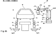
- FIG. 8A is a schematic side view of the robot system 1B in which the workpiece W is positioned at the first position as viewed from the downstream side in the conveyance direction of the workpiece W.
- FIG. 8B is a schematic side view of the robot system 1B in which the workpiece W is positioned at the second position, as viewed from the downstream side in the conveyance direction of the workpiece W.
- the rear robot arm 4b and the control device 5 are omitted in FIGS. 8A and 8B.
- the configuration of the robot system 1B according to the second embodiment is the same as that of the first embodiment except for the locator 7 for positioning the workpiece W.
- the locator 7 of the robot system 1B includes a locating pin 74 inserted through a hole h formed at the bottom of the workpiece W, a first moving module 71 and a second moving module 72 that allow the locating pin 74 to move in three axial directions perpendicular to each other.
- a rotation mechanism 75 is provided in addition to the third moving module 73. The rotation mechanism 75 rotates the locate pin 74 around a predetermined axis extending in the workpiece W conveyance direction.
- the first moving module 71 is a first base member that extends in a first horizontal direction parallel to the conveyance direction of the workpiece W, and a first sliding member that is slidably driven in the first horizontal direction with respect to the first base member. 1 slide member.
- the first base member of the first moving module 71 is fixed on a fixed base (not shown).
- the second moving module 72 includes a second base member extending in a second horizontal direction orthogonal to the conveyance direction of the workpiece W, and a second slide driven in the second horizontal direction with respect to the second base member. And a slide member.
- the second base member of the second movement module 72 is fixed on the first slide member of the first movement module 71.
- the third moving module 73 includes a third base member extending in the vertical direction and a third slide member that is slidably driven in the extending direction with respect to the third base member.
- the third base member of the third movement module 73 is erected on the second slide member of the second movement module 72.
- the rotation mechanism 75 is disposed on the third slide member of the third movement module 73.
- the rotation mechanism 75 moves the support member 76 and the third slide member so that the support member 76 supporting the locate pin 74 can rotate about a predetermined axis extending in the conveyance direction of the workpiece W with respect to the third slide member. Link.
- the robot arm 4 interferes with a part of the workpiece W. There may not be. Even in such a case, in the present embodiment, the work W is tilted by using the rotation mechanism 65, so that when the work W is in the first position, the joint location at a position where the work cannot be performed due to interference with the work W ( The second work location) is moved to a position where the robot arm 4 can work without interfering with the workpiece W.
- the locator 7 keeps the locating pin 74 inserted through the hole h, and the second moving module. 72, the work W is inclined toward the robot arm 4 a side by the cooperation of the third moving module 73 and the rotation mechanism 75.
- the locator 7 changes the position of the workpiece W from the first position where the joining operation cannot be performed to the predetermined location to the second position where the workpiece W can be joined to the predetermined location.
- the robot 3 included in the robot systems 1A and 1B is a robot that performs a joining operation on a plurality of joining locations, but the operation performed by the robot 3 is not limited thereto.
- the robot 3 may perform a painting operation, a coating operation, an inspection operation, or the like instead of the joining operation.
- the robot system 1A (or 1B) includes the two robot arms 4 and the four locators 6 (or 7).
- the number of robot arms 4 and the number of locators 6 (or 7) Is not limited to this.
- the arrangement of the robot arm 4 and the locator 6 is not limited to the arrangement shown in the above embodiment.
- the robot arms 4a and 4b are arranged at positions between the locators 6a and 6c in the transport direction and between the locators 6b and 6d in the transport direction.
- the robot arm 4b may be disposed upstream or downstream of the locators 6b and 6d in the transport direction.
- the robot arm 4b may be disposed upstream or downstream of the locators 6b and 6d in the transport direction.
- the transport device 2 may be configured by two parallel conveyors extending in the transport direction.
- the locator 6 may be disposed between the two conveyors.
- the rotation mechanism 75 rotates the locate pin 74 around a predetermined axis extending in parallel with the transport direction, but the rotation direction of the locate pin 74 is not limited to this.
- the rotation mechanism 75 may be rotated about a horizontal axis that is orthogonal to the transport direction.
- the configuration of locator 7 is not limited to that described above.
- the rotation mechanism 75 can rotate the third base member of the third movement module 73 with respect to the second slide member of the second movement module 72, so that the second movement module 72 and the third movement module 73 can rotate. It may be provided between.
Landscapes
- Engineering & Computer Science (AREA)
- Mechanical Engineering (AREA)
- Manufacturing & Machinery (AREA)
- Chemical & Material Sciences (AREA)
- Combustion & Propulsion (AREA)
- Transportation (AREA)
- Automatic Assembly (AREA)
- Manipulator (AREA)
- Automobile Manufacture Line, Endless Track Vehicle, Trailer (AREA)
- Resistance Welding (AREA)
Abstract
ロボットシステムは、複数の作業箇所のうち少なくとも第1及び第2の作業箇所に対して所定の作業を行う少なくとも1つのロボットと、互いに直交する3軸方向に移動自在のロケートピンをそれぞれ有し、ロケートピンが孔に挿通されたワークを、ロボットによって第1の作業箇所が作業される第1の位置に位置決めする複数のロケータと、複数のロケータの動作を制御する制御装置と、を備え、制御装置は、第1の作業箇所に対するロボットの作業が完了した後に、ロケートピンが孔に挿通された状態を維持したまま、ワークの位置を、第1の位置から、ロボットによって第2の作業箇所が作業される第2の位置に変更するよう複数のロケータを制御する。
Description
本発明は、自動車の車体等のワークに対して作業を行うロボットシステム及びそれを備える作業ラインに関する。
従来から、例えば自動車の車体組立ラインなどの作業ラインには、複数の作業ステージがラインに沿って設けられており、ワークは各作業ステージ間を搬送装置により搬送される。各作業ステージには、搬送されてきたワークを位置決めするロケータが配置され、当該ロケータに位置決めされたワークに対して、ロボットによる溶接や塗装などの各種作業が行われる。
例えば、特許文献1には、複数の溶接ステージを備え、スキッドによりワークとしての車体を各溶接ステージ間で搬送する車体組立ラインが開示される。この車体組立ラインの溶接ステージには、ロケートピンを先端に備えた位置決め装置と、単数又は複数の溶接ロボットが配置される。スキッドにより組立作業ステージに搬送された車体は、ロケータによりスキッドから所定レベルまでリフトアップされながら位置決めされる。そして、位置決めが完了すると、溶接ロボットにより、位置決めされた車体に対してスポット溶接が行われる。
ところで、ワークは、一般的に、ロボットに作業されるべき複数の作業箇所(例えば、スポット溶接されるべき複数の接合箇所など)を有する。ロボットは、ワークが有する複数の作業箇所のうち、該ロボットの可動範囲内に位置する作業箇所に対してしか作業を行うことができない。また、作業箇所が可動範囲内に位置する場合であっても、ワークの形状等によっては、ロボットとその作業箇所との間に配置されたワークの一部がロボットの障壁となって作業できない場合もある。このように、1つのロボットが作業を行える作業箇所は制限されるため、全ての作業箇所に対して作業を完了させるためには、作業箇所の位置に対応して多数のロボットを設置する必要があった。しかしながら、例えば設置スペースやコスト等の観点から、できる限り少ないロボットで作業を完了できる作業ラインが望まれる場合がある。
そこで、本発明は、複数の作業箇所を有するワークに対して、より少ないロボットで作業を完了することができるロボットシステム及びそれを備える作業ラインを提供することを目的とする。
本発明の一態様に係るロボットシステムは、複数の孔を有すると共に、複数の作業箇所を有するワークに対して作業を行うロボットシステムであって、前記複数の作業箇所のうち少なくとも第1及び第2の作業箇所に対して所定の作業を行う少なくとも1つのロボットと、互いに直交する3軸方向に移動自在のロケートピンをそれぞれ有し、前記ロケートピンが前記孔に挿通された前記ワークを、前記ロボットによって前記第1の作業箇所が作業される第1の位置に位置決めする複数のロケータと、前記複数のロケータの動作を制御する制御装置と、を備え、前記制御装置は、前記第1の作業箇所に対する前記ロボットの作業が完了した後に、前記ロケートピンが前記孔に挿通された状態を維持したまま、前記ワークの位置を、前記第1の位置から、前記ロボットによって前記第2の作業箇所が作業される第2の位置に変更するよう前記複数のロケータを制御する。
上記の構成によれば、第1及び第2の作業箇所を有するワークに対して、第1の作業箇所に対するロボットの作業が完了した後に、ロケータが、ワークの位置を第2の作業箇所に対して作業を行なうための位置に変更する。このため、例えばワークが第1の位置にあるときには、ロボットが第2の作業箇所に対して作業を行なうことができない場合であっても、当該ロボットに第2の作業箇所に対して作業させることができる。従って、第1及び第2の作業箇所に対し同じロボットで作業可能になるため、複数の作業箇所を有するワークに対して、より少ないロボットで作業を完了することができる。
上記のロボットシステムにおいて、前記ロケータは、第1の水平方向に前記ロケートピンを移動させる第1移動モジュールと、第1の水平方向と直交する第2の水平方向に前記ロケートピンを移動させる第2移動モジュールと、鉛直方向に前記ロケートピンを移動させる第3移動モジュールとを含み、前記制御装置は、前記ワークの位置を前記第1の位置から前記第2の位置に変更するために、前記第1移動モジュール、前記第2移動モジュール及び前記第3移動モジュールの少なくとも1つを制御してもよい。
上記のロボットシステムにおいて、例えば、前記複数のロケータが、前記ワークの位置を前記第1の位置から前記第2の位置に変更することにより、前記第2の作業箇所は、前記ロボットの可動範囲外から、前記ロボットの可動範囲内に移動する。
上記のロボットシステムにおいて、例えば、前記複数のロケータが、前記ワークの位置を前記第1の位置から前記第2の位置に変更することにより、前記第2の作業箇所は、前記ワークとの干渉により前記ロボットを用いて作業できない位置から、前記ロボットが前記ワークと干渉することなく作業可能な位置に移動する。
上記のロボットシステムにおいて、前記複数のロケータは、前記ロケートピンを水平方向に延びる所定の軸まわりに回動させる回動機構を備え、前記制御装置は、前記ワークの位置を前記第1の位置から前記第2の位置に変更するために、前記回動機構を制御して前記ワークを傾斜させてもよい。
上記のロボットシステムにおいて、例えば、前記ワークは、前記複数の作業箇所としての複数の接合箇所を有する自動車の車体又は車体の一部を構成する部品であり、前記ロボットは、前記第1及び第2の作業箇所に対して接合を行うロボットである。
また、本発明の一態様に係る作業ラインは、ワークの搬送経路に沿って該ワークに対して所定の作業が行われる複数の作業ステージが設けられた作業ラインであって、前記ワークは、第1及び第2の作業箇所を有し、前記複数の作業ステージの少なくとも1つに配置された、上記のいずれかのロボットシステムと、前記複数の作業ステージの互いに隣接する2つの作業ステージ間で前記ワークを搬送する搬送装置と、を備える。
本発明によれば、複数の作業箇所を有するワークに対して、より少ないロボットで作業を完了することができるロボットシステム及びそれを備える作業ラインを提供することができる。
[第1実施形態]
以下、本発明の第1実施形態について図面を参照しつつ説明する。なお、以下では、全ての図面を通じて同一または相当する要素には同じ符号を付して、重複する説明は省略する。
以下、本発明の第1実施形態について図面を参照しつつ説明する。なお、以下では、全ての図面を通じて同一または相当する要素には同じ符号を付して、重複する説明は省略する。
(作業ラインの構成)
図1は、第1実施形態に係る作業ライン100の模式的な平面図である。本実施形態に係る作業ライン100は、ワークを搬送しながら当該ワークに対して作業を行うワーク搬送システムであり、例えば、自動車の車体を組み立てる車体組立ラインである。以下、作業ライン100において搬送される車体のボディ又はその一部を構成するフレーム等の部品をワークWと称する。また、作業ライン100においてワークWは、図1の紙面右側から紙面左側に搬送されるものとして説明し、便宜上、図1の紙面下側を手前側とし、図1の紙面上側を奥側として説明する。
図1は、第1実施形態に係る作業ライン100の模式的な平面図である。本実施形態に係る作業ライン100は、ワークを搬送しながら当該ワークに対して作業を行うワーク搬送システムであり、例えば、自動車の車体を組み立てる車体組立ラインである。以下、作業ライン100において搬送される車体のボディ又はその一部を構成するフレーム等の部品をワークWと称する。また、作業ライン100においてワークWは、図1の紙面右側から紙面左側に搬送されるものとして説明し、便宜上、図1の紙面下側を手前側とし、図1の紙面上側を奥側として説明する。
作業ライン100には、ワークWの搬送経路に沿って、該ワークWに対して所定の作業が行われる複数の作業ステージ(作業領域)S,S’,S’’が設けられる。作業ステージS,S’,S’’には、ワークWに対して作業を行うロボットシステム1A,1A’,1A’’がそれぞれ配置される。本実施形態において、ワークWは、接合されるべき接合箇所が多数設けられており、ロボットシステム1A,1A’,1A’’は、ワークWが有する接合箇所に対して接合作業を行う。但し、ロボットシステム1A,1A’,1A’’は、ワークWに対して互いに異なる種類の作業を行うものであってもよい。図例では、3つの作業ステージS,S’,S’’が示されるが、作業ライン100に設けられる作業ステージの数は、1つでもよいし、2つでも4つ以上でもよい。
作業ライン100には、互いに隣接する2つの作業ステージ間で搬送方向にワークWを搬送する搬送装置2が設けられている。搬送装置2は、例えばコンベアである。但し、搬送装置2の構成は特に限定されず、例えば搬送装置2は、ワークWを吊下げて搬送する構成であってもよいし、搬送方向に移動可能な台車式であってもよい。搬送装置2は、互いに隣接する2つの作業ステージに対して1つ設けられてもよいし、作業ライン100全体に対して1つ設けられてもよい。
作業ライン100において、例えば、作業ステージS’では、ロボットシステム1A’により、ワークWが有する所定の複数の接合箇所に対して接合作業が行われる。ロボットシステム1A’による作業が完了すると、ワークWは搬送装置2により次の作業ステージSに搬送される。次の作業ステージSでは、ロボットシステム1Aにより、作業ステージS’で接合された箇所とは別の複数の接合箇所に対して接合作業が行われる。ロボットシステム1Aによる作業が完了すると、その後、ワークWは搬送装置2により次の作業ステージS’’に搬送される。作業ステージS’’では、ロボットシステム1A’’により、作業ステージS’,Sで接合された箇所とは別の複数の接合箇所に対して接合作業が行われる。こうして、ワークWは、作業ライン100において搬送される間に、ワークWが有する多数の接合箇所に対して次々に作業が行われる。
以下、作業ライン100が備えるロボットシステムの一例として、作業ステージSに配置されたロボットシステム1Aについて説明する。
(ロボットシステムの構成)
図1に示すように、ロボットシステム1Aは、2つのロボットアーム4a,4bとこれらの動作を司る制御装置5を備える。図2は、作業ステージSに配置されたロボットシステム1Aの斜視図である。また、図3は、ロボットシステム1AをワークWの搬送方向下流側から見た概略側面図である。なお、簡略化のため、図1では、他のロボットシステム1A’,1A’’が備える要素を省略しており、また、図2では、手前側のロボットアーム4aを省略している。
図1に示すように、ロボットシステム1Aは、2つのロボットアーム4a,4bとこれらの動作を司る制御装置5を備える。図2は、作業ステージSに配置されたロボットシステム1Aの斜視図である。また、図3は、ロボットシステム1AをワークWの搬送方向下流側から見た概略側面図である。なお、簡略化のため、図1では、他のロボットシステム1A’,1A’’が備える要素を省略しており、また、図2では、手前側のロボットアーム4aを省略している。
図1に示すように、本実施形態では、2つのロボットアーム4a,4bが、ワークWの搬送経路を挟んで両側(即ち、手前側及び奥側)にそれぞれ配置されている。
各ロボットアーム4a,4bの先端には、エンドエフェクタ47が装着される。ロボットアーム4a又は4bとそれに装着されるエンドエフェクタ47と、ロボットアーム4及びエンドエフェクタ47の動作を司る制御装置5とにより、ワークWに対し接合作業を行う1つのロボット3が構成される。
本実施形態では、ロボット3は、接合作業としてスポット溶接作業を実行できるよう、各ロボットアーム4a,4bの先端にエンドエフェクタ47としてスポット溶接ガンが装着される。但し、ロボット3が行う接合作業は、スポット溶接に限定されず、例えば、摩擦撹拌接合や、リベット接合、アーク溶接、ねじやボルト、ナット等を用いた接合などであってもよい。
ロボットアーム4a,4bは、互いに同様の構成を有しているため、以下、ロボットアーム4a,4bを総称する場合、及びロボットアーム4a,4bのうち任意に選択したロボットアームに対して説明する場合、符号の英字を省略してロボットアーム4とする。
図3に示すように、ロボットアーム4は、3以上の複数の関節JT1~JT6を有する多関節ロボットアームであって、複数のリンク41~46が順次連結されて構成されている。より詳しくは、第1関節JT1では、基台48と、第1リンク41の基端部とが、鉛直方向に延びる軸回りに回転可能に連結されている。第2関節JT2では、第1リンク41の先端部と、第2リンク42の基端部とが、水平方向に延びる軸回りに回転可能に連結されている。第3関節JT3では、第2リンク42の先端部と、第3リンク43の基端部とが、水平方向に延びる軸回りに回転可能に連結されている。第4関節JT4では、第3リンク43の先端部と、第4リンク44の基端部とが、第4リンク43の長手方向に延びる軸回りに回転可能に連結されている。第5関節JT5では、第4リンク44の先端部と、第5リンク45の基端部とが、リンク44の長手方向と直交する軸回りに回転可能に連結されている。第6関節JT6では、第5リンク45の先端部と第6リンク46の基端部とが、捻れ回転可能に連結されている。そして、第6リンク46の先端部にはメカニカルインターフェースが設けられている。このメカニカルインターフェースに、エンドエフェクタ47が着脱可能に装着される。
関節JT1~JT6には、それが連結する2つの部材を相対的に回転させるアクチュエータの一例としての駆動モータ(図示せず)が設けられている。駆動モータは、例えば、制御装置5によってサーボ制御されるサーボモータである。また、関節JT1~JT6には、駆動モータの回転位置を検出するための回転センサと、駆動モータの回転を制御する電流を検出するための電流センサ(いずれも図示せず)とが設けられている。回転センサは、例えばエンコーダである。
制御装置5は、例えば、マイクロコントローラ、MPU、PLC(Programmable Logic Controller)、論理回路等からなる演算部(図示せず)と、ROMやRAM等からなるメモリ部(図示せず)とにより構成されている。
また、図1に示すように、ロボットシステム1Aは、4つのロケータ6a,6b,6c,6dを備える。ロケータ6a,6b,6c,6dは、互いに協動してワークWの位置決めを行う。本実施形態では、ロケータ6aとロケータ6bとが、ワークWの搬送経路を挟んで両側(即ち、手前側及び奥側)にそれぞれ対向して配置される。また、ロケータ6cとロケータ6dとが、ロケータ6aとロケータ6bよりも搬送方向上流側において、ワークWの搬送経路を挟んで両側(即ち、手前側及び奥側)にそれぞれ対向して配置される。また、図1に示すように、本実施形態では、搬送方向におけるロケータ6aとロケータ6cの間において、ロケータ6a,6cより手前側にロボットアーム4aが配置される。また、搬送方向におけるロケータ6bとロケータ6dの間において、ロケータ6b,6dより奥側にロボットアーム4bが配置される。
ロケータ6a,6b,6c,6dは、互いに同様の構成を有しているため、以下、ロケータ6a,6b,6c,6dを総称する場合、及びロケータ6a,6b,6c,6dのうち任意に選択したロケータに対して説明する場合、符号の英字を省略してロケータ6とする。
ロケータ6は、搬送装置2により作業ステージSに搬送されたワークWを互いに協動して支持するとともに、ロボット3により作業可能な所定の箇所に当該ワークWの位置決めを行う。図3に示すように、ロケータ6は、ワークWの底部に形成された孔hに挿通されるロケートピン64を有する。ロケータ6は、ロケートピン64を互いに直交する3軸方向に移動自在となるよう、第1移動モジュール61、第2移動モジュール62及び第3移動モジュール63を備えており、下から上に向かってこの順に連結されて構成される。
より詳しくは、第1移動モジュール61は、ワークWの搬送方向に平行な第1の水平方向にロケートピン64を移動させる。第1移動モジュール61は、第1の水平方向に延びる第1ベース部材と、第1ベース部材に対して第1の水平方向にスライド駆動される第1スライド部材とを有する。第1移動モジュール61の第1ベース部材は、図示しない固定台上に固定されている。
また、第2移動モジュール62は、搬送方向と直交する第2の水平方向にロケートピン64を移動させる。第2移動モジュール62は、第2の水平方向に延びる第2ベース部材と、該第2ベース部材に対して第2の水平方向にスライド駆動される第2スライド部材とを有する。第2移動モジュール62の第2ベース部材は、第1移動モジュール61の第1スライド部材上に固定されている。
また、第3移動モジュール63は、鉛直方向にロケートピン64を移動させる。第3移動モジュール63は、鉛直方向に延びる第3ベース部材と、該第3ベース部材に対して鉛直方向にスライド駆動される第3スライド部材とを有する。第3移動モジュール63の第3ベース部材は、第2移動モジュール62の第2スライド部材上にて立設されている。第3スライド部材には、ロケートピン64が鉛直上向きに固定されている。
ロケータ6は、ワークWの孔hにロケートピン64を挿通させることにより、ワークWを支持する。ロケートピン64の周りには、ワークWの孔hの周りに当接する支持面が設けられてもよい。また、ロケートピン64には、ワークWの孔hに挿通された後、ワークWをクランプする機能が備わっていてもよい
なお、本実施形態では、ロケータ6は、第1移動モジュール61、第2移動モジュール62及び第3移動モジュール63が、下から上に向かってこの順に配置されているが、第1移動モジュール61、第2移動モジュール62及び第3移動モジュール63の配置は特に限定されない。また、ロケートピン64が挿通される孔hは、ワークWの底部に設けられていなくてもよく、例えばワークWの側方に設けられていてもよい。この場合、ロケートピン64は水平方向を向くよう配置されてもよい。
第1移動モジュール61、第2移動モジュール62及び第3移動モジュール63は、それぞれ、第1スライド部材、第2スライド部材及び第3スライド部材をスライド駆動するための駆動モータ(図示せず)を備える。本実施形態では、制御装置5がロボットアーム4だけでなく、ロケータ6の動作も制御する。即ち、制御装置5は、第1移動モジュール61、第2移動モジュール62及び第3移動モジュール63が備える各駆動モータを動作させて、ロケートピン64の位置を任意に変更することができる。但し、ロボットアーム4とロケータ6とは、別々の制御装置により制御されてもよい。
次に、ロボットシステム1Aによる接合作業の流れの一例を、図4A~図6Bを参照しながら説明する。なお、接合作業におけるロボットアーム4、エンドエフェクタ47及びロケータ6の動作は、制御装置5により制御される。
図4Aは、作業ステージSへワークWが搬送された直後のロボットシステム1Aの概略側面図である。但し、簡略化のため、図4Aではロボットアーム4を省略している。図4Aに示すように、作業ステージSへワークWが搬送されるまでは、ロケータ6は、搬送されるワークWに接触しないようロケートピン64を下方に退避させた状態にある。本実施形態では、搬送装置2は、ロケートピン64とそれに挿通される孔hとが鉛直方向に一致する所定の位置までワークWを搬送する。
図4Bは、図4Aに示すロボットシステム1Aの模式的な平面図である。図4Bには、ロボットアーム4a,4bの可動範囲Ra,Rbがそれぞれ二点鎖線で囲まれえて示される。ここで、可動範囲Ra,Rbは、ロボットアーム4a,4bの各部(エンドエフェクタ47を含む。)が構造上動きうる最大の範囲をいう。但し、この構造上動きうる最大の範囲内に電気的又は機械的ストッパーがある場合は、当該ストッパーによりロボットアーム4a,4bの各部が作動できない範囲を除く。
後述するように、本実施形態では、作業ステージSへ搬送されたワークWは、ロケータ6によって、まず第1の位置へ位置決めされ、その後、第1の位置とは異なる第2の位置へ位置決めされる。ワークWが有する複数の接合箇所のうち、ワークWが第1の位置にあるときに、ロボットアーム4により接合される箇所を第1の接合箇所(第1の作業箇所)と称し、また、ワークWが有する複数の接合箇所のうち、ワークWが第2の位置にあるときに、ロボットアーム4により接合される箇所を第2の接合箇所(第2の作業箇所)と称する。なお、本実施形態では、第1及び第2の接合箇所は、それぞれ複数であるが、1つであってもよい。
図5Aは、ワークWを第1の位置へ位置決めしたロボットシステム1Aの概略側面図である。図4Aに示すように、搬送装置2がワークWを所定の位置まで搬送すると、ロケータ6は、第3移動モジュール63を駆動させ、ロケートピン64をワークWの孔hに挿通させ、図5Aに示すようにワークWを支持する。こうして、ロケータ6は、ワークWの位置を、予め設定された第1の位置へ位置決めする。
図5Bは、図5Aに示すロボットシステム1Aの模式的な平面図である。ワークWが第1の位置に位置決めされると、ロボットアーム4は、ワークWが有する複数の接合箇所のうち第1の接合箇所に対して接合作業を行う。第1の接合箇所は、ワークWが第1の位置にあるときに、ロボットアーム4a,4bのいずれかの可動範囲Ra,Rb内にある。本実施形態では、第1の接合箇所は、図5Bでハッチングされた領域A内にある。
図6Aは、ワークWを第2の位置へ位置決めしたロボットシステム1Aの概略側面図である。図5Aに示す第1の位置において第1の接合箇所に対するロボットアーム4の作業が完了した後に、ロケータ6は、ロケートピン64が孔hに挿通された状態を維持したまま、ワークWの位置を、第1の位置から第2の位置に変更する。図4A~図6Bに示す例では、第1の接合箇所に対してロボットアーム4の作業が完了すると、ロケータ6は、第1移動モジュール61を駆動させ、ロケートピン64を搬送方向(即ち第1の水平方向)に沿って移動させて、ワークWの位置を予め設定された第2の位置へ変更させる。
図6Bは、図6Aに示すロボットシステム1Aの模式的な平面図である。ワークWが第2の位置に位置決めされると、ロボットアーム4は、ワークWが有する複数の接合箇所のうち第2の接合箇所に対して接合作業を行う。第2の接合箇所は、ワークWが第2の位置にあるときに、ロボットアーム4a,4bのいずれかの可動範囲Ra,Rb内にある。本実施形態では、第2の接合箇所は、図6Bでハッチングされた領域B内にある。
本実施形態では、第2の接合箇所は、ロケータ6がワークWを第1の位置に位置決めしたときには、第2の接合箇所はロボットアーム4の可動範囲Ra,Rb外にある。そして、ロケータ6が、ワークWの位置を、第1の位置から第2の位置に変更したときに、第2の接合箇所はロボットアーム4の可動範囲Ra,Rbに入る。
このように、本実施形態では、ワークWが第1の位置に位置する場合に物理的に作業を行なうことができない第2の接合箇所に対して作業を行なえるように、ロケータ6は、第1の位置での作業完了後にワークWを第2の位置に変更する。
図7A及び図7Bに、図4A~図6Bに示したロボットシステム1Aの動作例とは別の動作例を示す。図4A~図6Bの動作例では、ワークWを搬送方向(第1の水平方向)に移動させることによりワークWの位置を第1の位置から第2の位置に変更させる例を示したが、図7A及び図7Bの動作例では、ワークWを搬送方向に直交し、且つ水平な方向(第2の水平方向)に移動させることによりワークWの位置を第1の位置から第2の位置に変更させる。
図7Aは、ワークWを第1の位置へ位置決めしたロボットシステム1AをワークWの搬送方向下流側から見た概略側面図である。図7Bは、ワークを第2の位置へ位置決めしたロボットシステム1Aをワークの搬送方向下流側から見た概略側面図である。なお、簡略化のため、図7A及び図7Bでは奥側のロボットアーム4bや制御装置5を省略している。
ワークWが第1の位置に位置するとき、ロボットアーム4a,4bの中間付近に位置するワークWの中央部分は、ロボットアーム4a,4bの双方の可動範囲Ra,Rb外である場合がある。あるいは、ワークWの該中央部分は、可動範囲Ra又はRb内に位置していたとしても、ロボットアーム4a又は4bによる作業が行いにくい場合がある。このような場合、図7Bに示すように、第1の接合箇所に対する作業が完了した後に、ロケータ6は、第2移動モジュール62を駆動させ、ロケートピン64を搬送方向に直交する第2の水平方向に移動させる。これにより、ワークWの位置を、第2の位置にあるときと比べてロボットアーム4aに近い予め設定された第2の位置へ変更させる。
なお、ロボットシステム1Aの動作例は、上記したものに限定されず、例えば、第3移動モジュール63を駆動させて、ワークWの位置を第1の位置から第2の位置に変更させてもよい。また、例えば、第1移動モジュール61、第2移動モジュール62及び第3移動モジュール63の2つ以上を駆動させて、ワークWの位置を第1の位置から第2の位置に変更させてもよい。また、例えば、第1移動モジュール61及び第2移動モジュール62の協動によりワークWを旋回させることによって、ワークWの位置を第1の位置から第2の位置に変更させてもよい。
以上に説明したように、本実施形態に係るロボットシステム1Aは、第1及び第2の接合箇所を有するワークWに対して、第1の接合箇所に対するロボット3の作業が完了した後に、ロケータ6が、ワークWの位置を第2の接合箇所に対して作業を行なうための位置に変更する。このため、例えばワークWが第1の位置にあるときには、ロボット3が第2の接合箇所に対して作業を行なうことができない場合であっても、当該ロボット3に第2の接合箇所に対して作業させることができる。従って、第1及び第2の接合箇所に対し同じロボット3で作業可能になるため、複数の接合箇所を有するワークWに対して、より少ないロボット3で作業を完了することができる。
[第2実施形態]
次に、第2実施形態に係るロボットシステム1Bについて、図8A及び図8Bを参照しつつ説明する。図8Aは、ワークWを第1の位置へ位置決めしたロボットシステム1BをワークWの搬送方向下流側から見た概略側面図である。図8Bは、ワークWを第2の位置へ位置決めしたロボットシステム1BをワークWの搬送方向下流側から見た概略側面図である。なお、簡略化のため、図8A及び図8Bでは奥側のロボットアーム4bや制御装置5を省略している。
次に、第2実施形態に係るロボットシステム1Bについて、図8A及び図8Bを参照しつつ説明する。図8Aは、ワークWを第1の位置へ位置決めしたロボットシステム1BをワークWの搬送方向下流側から見た概略側面図である。図8Bは、ワークWを第2の位置へ位置決めしたロボットシステム1BをワークWの搬送方向下流側から見た概略側面図である。なお、簡略化のため、図8A及び図8Bでは奥側のロボットアーム4bや制御装置5を省略している。
第2実施形態に係るロボットシステム1Bは、ワークWの位置決めを行うロケータ7以外の構成は第1実施形態と同様である。ロボットシステム1Bのロケータ7は、ワークWの底部に形成された孔hに挿通されるロケートピン74、ロケートピン74を互いに直交する3軸方向に移動自在とする第1移動モジュール71、第2移動モジュール72及び第3移動モジュール73に加えて、回動機構75を備えている。回動機構75は、ロケートピン74をワークWの搬送方向に延びる所定の軸まわりに回動させる。
より詳しくは、第1移動モジュール71は、ワークWの搬送方向に平行な第1の水平方向に延びる第1ベース部材と、第1ベース部材に対して第1の水平方向にスライド駆動される第1スライド部材とを有する。第1移動モジュール71の第1ベース部材は、図示しない固定台上に固定されている。また、第2移動モジュール72は、ワークWの搬送方向と直交する第2の水平方向に延びる第2ベース部材と、該第2ベース部材に対して第2の水平方向にスライド駆動される第2スライド部材とを有する。第2移動モジュール72の第2ベース部材は、第1移動モジュール71の第1スライド部材上に固定されている。また、第3移動モジュール73は、鉛直方向に延びる第3ベース部材と、該第3ベース部材に対してその延びる方向にスライド駆動される第3スライド部材とを有する。第3移動モジュール73の第3ベース部材は、第2移動モジュール72の第2スライド部材上にて立設されている。
第3移動モジュール73の第3スライド部材に、回動機構75が配置される。回動機構75は、ロケートピン74を支持する支持部材76が第3スライド部材に対してワークWの搬送方向に延びる所定の軸まわり回動可能となるよう、支持部材76と第3スライド部材とを連結する。
ワークWが図8Aに示す第1の位置に位置するとき、ワークWが有する接合箇所によっては、接合作業を行なうとするとロボットアーム4がワークWの一部と干渉してしまうため、作業を行なえない場合がある。このような場合でも、本実施形態では、回動機構65を用いてワークWを傾斜させることにより、ワークWが第1の位置にあるときにはワークWとの干渉により作業できない位置にある接合箇所(第2の作業箇所)を、ロボットアーム4がワークWと干渉することなく作業できる位置に移動させる。
具体的には、第1の位置に位置するワークWの第1の接合箇所に対する作業が完了した後に、ロケータ7は、ロケートピン74が孔hに挿通された状態を維持したまま、第2移動モジュール72、第3移動モジュール73及び回動機構75の協動により、ワークWをロボットアーム4a側に傾斜させる。こうして、ロケータ7は、ワークWの位置を、所定の箇所に対して接合作業ができなかった第1の位置から、当該所定の箇所に対して接合可能となる第2の位置へ変更させる。
本実施形態でも、第1実施形態と同様の効果を得ることができる。
[その他実施形態]
本発明は上述した実施形態に限定されるものではなく、本発明の要旨を逸脱しない範囲で種々の変形が可能である。
本発明は上述した実施形態に限定されるものではなく、本発明の要旨を逸脱しない範囲で種々の変形が可能である。
例えば、上記実施形態では、ロボットシステム1A,1Bが備えるロボット3は、複数の接合箇所に対して接合作業を行うロボットであったが、ロボット3が行う作業はこれに限定されない。例えば、ロボット3は、接合作業の代わりに、塗装作業、塗布作業、検査作業などを行うものであってもよい。
また、上記実施形態では、ロボットシステム1A(又は1B)が、2つのロボットアーム4と4つのロケータ6(又は7)を備えていたが、ロボットアーム4の数及びロケータ6(又は7)の数はこれに限定されない。
また、ロボットアーム4とロケータ6(又は7)の配置は、上記実施形態で示された配置に限定されない。例えば、第1実施形態では、搬送方向におけるロケータ6a,6cの間の位置と搬送方向におけるロケータ6b,6dの間の位置に、ロボットアーム4a,4bがそれぞれ配置されたが、例えばロボットアーム4aは搬送方向におけるロケータ6a,6cより上流側又は下流側に配置されてもよいし、ロボットアーム4bは搬送方向におけるロケータ6b,6dより上流側又は下流側に配置されてもよい。
また、搬送装置2は、搬送方向に延びる互いに平行な2つコンベアにより構成されてもよく、この場合、2つのコンベアの間にロケータ6が配置されてもよい。
また、第2実施形態では、回動機構75は、ロケートピン74を搬送方向に平行に延びる所定の軸まわりに回動させたが、ロケートピン74の回動方向はこれに限定されない。例えば、回動機構75は、搬送方向に直交し且つ水平な軸まわりに回動させるものであってもよい。また、ロケータ7の構成は、上記したものに限定されない。例えば、回動機構75は、第2移動モジュール72の第2スライド部材に対して第3移動モジュール73の第3ベース部材を回動できるように、第2移動モジュール72と第3移動モジュール73との間に設けられていてもよい。
1A,1B ロボットシステム
2 搬送装置
3 ロボット
5 制御装置
6(6a,6b,6c,6d) ロケータ
61 第1移動モジュール
62 第2移動モジュール
63 第3移動モジュール
64 ロケートピン
7(7a,7b,7c,7d) ロケータ
71 第1移動モジュール
72 第2移動モジュール
73 第3移動モジュール
74 ロケートピン
75 回動機構
100 作業ライン
Ra,Rb 可動範囲
S 作業ステージ
W ワーク
h 孔
2 搬送装置
3 ロボット
5 制御装置
6(6a,6b,6c,6d) ロケータ
61 第1移動モジュール
62 第2移動モジュール
63 第3移動モジュール
64 ロケートピン
7(7a,7b,7c,7d) ロケータ
71 第1移動モジュール
72 第2移動モジュール
73 第3移動モジュール
74 ロケートピン
75 回動機構
100 作業ライン
Ra,Rb 可動範囲
S 作業ステージ
W ワーク
h 孔
Claims (7)
- 複数の孔を有すると共に、複数の作業箇所を有するワークに対して作業を行うロボットシステムであって、
前記複数の作業箇所のうち少なくとも第1及び第2の作業箇所に対して所定の作業を行う少なくとも1つのロボットと、
互いに直交する3軸方向に移動自在のロケートピンをそれぞれ有し、前記ロケートピンが前記孔に挿通された前記ワークを、前記ロボットによって前記第1の作業箇所が作業される第1の位置に位置決めする複数のロケータと、
前記複数のロケータの動作を制御する制御装置と、を備え、
前記制御装置は、前記第1の作業箇所に対する前記ロボットの作業が完了した後に、前記ロケートピンが前記孔に挿通された状態を維持したまま、前記ワークの位置を、前記第1の位置から、前記ロボットによって前記第2の作業箇所が作業される第2の位置に変更するよう前記複数のロケータを制御する、ロボットシステム。 - 前記ロケータは、第1の水平方向に前記ロケートピンを移動させる第1移動モジュールと、第1の水平方向と直交する第2の水平方向に前記ロケートピンを移動させる第2移動モジュールと、鉛直方向に前記ロケートピンを移動させる第3移動モジュールとを含み、
前記制御装置は、前記ワークの位置を前記第1の位置から前記第2の位置に変更するために、前記第1移動モジュール、前記第2移動モジュール及び前記第3移動モジュールの少なくとも1つを制御する、請求項1に記載のロボットシステム。 - 前記複数のロケータが、前記ワークの位置を前記第1の位置から前記第2の位置に変更することにより、前記第2の作業箇所は、前記ロボットの可動範囲外から、前記ロボットの可動範囲内に移動する、請求項1又は2に記載のロボットシステム。
- 前記複数のロケータが、前記ワークの位置を前記第1の位置から前記第2の位置に変更することにより、前記第2の作業箇所は、前記ワークとの干渉により前記ロボットを用いて作業できない位置から、前記ロボットが前記ワークと干渉することなく作業可能な位置に移動する、請求項1又は2に記載のロボットシステム。
- 前記複数のロケータは、前記ロケートピンを水平方向に延びる所定の軸まわりに回動させる回動機構を備え、前記制御装置は、前記ワークの位置を前記第1の位置から前記第2の位置に変更するために、前記回動機構を制御して前記ワークを傾斜させる、請求項1~4のいずれか1項に記載のロボットシステム。
- 前記ワークは、前記複数の作業箇所としての複数の接合箇所を有する自動車の車体又は車体の一部を構成する部品であり、
前記ロボットは、前記第1及び第2の作業箇所に対して接合を行うロボットである、請求項1~5のいずれか1項に記載のロボットシステム。 - ワークの搬送経路に沿って該ワークに対して所定の作業が行われる複数の作業ステージが設けられた作業ラインであって、
前記ワークは、第1及び第2の作業箇所を有し、
前記複数の作業ステージの少なくとも1つに配置された、請求項1~6のいずれかに記載のロボットシステムと、
前記複数の作業ステージの互いに隣接する2つの作業ステージ間で前記ワークを搬送する搬送装置と、を備える、作業ライン。
Priority Applications (2)
| Application Number | Priority Date | Filing Date | Title |
|---|---|---|---|
| CN201880026288.6A CN110545952B (zh) | 2017-04-25 | 2018-04-24 | 机器人系统和具备该机器人系统的工作线 |
| US16/608,317 US11332209B2 (en) | 2017-04-25 | 2018-04-24 | Robot system and work line including the same |
Applications Claiming Priority (2)
| Application Number | Priority Date | Filing Date | Title |
|---|---|---|---|
| JP2017086363A JP6842983B2 (ja) | 2017-04-25 | 2017-04-25 | ロボットシステム及びそれを備える作業ライン |
| JP2017-086363 | 2017-04-25 |
Publications (1)
| Publication Number | Publication Date |
|---|---|
| WO2018199073A1 true WO2018199073A1 (ja) | 2018-11-01 |
Family
ID=63918511
Family Applications (1)
| Application Number | Title | Priority Date | Filing Date |
|---|---|---|---|
| PCT/JP2018/016567 Ceased WO2018199073A1 (ja) | 2017-04-25 | 2018-04-24 | ロボットシステム及びそれを備える作業ライン |
Country Status (4)
| Country | Link |
|---|---|
| US (1) | US11332209B2 (ja) |
| JP (1) | JP6842983B2 (ja) |
| CN (1) | CN110545952B (ja) |
| WO (1) | WO2018199073A1 (ja) |
Families Citing this family (7)
| Publication number | Priority date | Publication date | Assignee | Title |
|---|---|---|---|---|
| DE102020200472A1 (de) * | 2019-06-13 | 2020-12-17 | Sms Group Gmbh | Fixieren eines Bandendabschnitts eines Metallbandcoils an einer benachbarten Bandwicklung |
| JP2021030378A (ja) * | 2019-08-26 | 2021-03-01 | 川崎重工業株式会社 | 作業ライン用搬送システムおよびそれを備えるロボットシステム |
| CN113042986A (zh) * | 2019-12-27 | 2021-06-29 | 沈阳新松机器人自动化股份有限公司 | 一种智能装配系统 |
| CN112605972A (zh) * | 2020-11-13 | 2021-04-06 | 机械工业第九设计研究院有限公司 | 滑板支点自动调整机器人系统及方法 |
| JP7212188B2 (ja) * | 2020-12-04 | 2023-01-24 | 株式会社大気社 | 製造装置および製造装置の制御方法 |
| JP7068430B1 (ja) | 2020-12-04 | 2022-05-16 | 株式会社大気社 | 製造装置および製造装置の制御方法 |
| JP7604563B1 (ja) | 2023-06-28 | 2024-12-23 | 株式会社ジーテクト | スポット溶接設備 |
Citations (10)
| Publication number | Priority date | Publication date | Assignee | Title |
|---|---|---|---|---|
| JPS61176599U (ja) * | 1985-04-24 | 1986-11-04 | ||
| JPH0360943A (ja) * | 1989-07-31 | 1991-03-15 | Nissan Motor Co Ltd | ロケートピンによるワーク位置決め方法 |
| JPH03248778A (ja) * | 1990-02-22 | 1991-11-06 | Nissan Motor Co Ltd | 自動車車体の溶接装置 |
| JPH04250931A (ja) * | 1990-12-28 | 1992-09-07 | Mazda Motor Corp | ワーク支持台車及びそれを使用したワークの加工又は組立方法 |
| JPH08174448A (ja) * | 1994-12-27 | 1996-07-09 | Nissan Motor Co Ltd | 協調型無人搬送車 |
| JP2002254260A (ja) * | 2001-02-26 | 2002-09-10 | Nissan Motor Co Ltd | 車両の組立方法および組立装置 |
| JP2006272492A (ja) * | 2005-03-29 | 2006-10-12 | Nissan Motor Co Ltd | 部品組立方法と部品組立装置および部品組み立てに用いる脱着工具 |
| JP2008207735A (ja) * | 2007-02-27 | 2008-09-11 | Honda Motor Co Ltd | 車体の溶接装置および車体の生産方法 |
| JP2009179142A (ja) * | 2008-01-30 | 2009-08-13 | Honda Motor Co Ltd | タイヤ組み付け装置及び方法 |
| US20120146274A1 (en) * | 2010-12-08 | 2012-06-14 | Kia Motors Corporation | Vehicle body moving cart |
Family Cites Families (21)
| Publication number | Priority date | Publication date | Assignee | Title |
|---|---|---|---|---|
| JPS6385384U (ja) * | 1986-11-19 | 1988-06-03 | ||
| US5275326A (en) * | 1992-08-21 | 1994-01-04 | Lsi Logic Corporation | Guide hole sleeves for boat transports supporting semiconductor device assemblies |
| US6047875A (en) * | 1995-09-20 | 2000-04-11 | Unitek Miyachi Coporation | Reflow soldering self-aligning fixture |
| JP3206456B2 (ja) * | 1996-10-24 | 2001-09-10 | 三菱自動車工業株式会社 | エンジン・トランスミッション組付用搬送パレット |
| JP3962552B2 (ja) * | 2001-03-12 | 2007-08-22 | 日産自動車株式会社 | 車体搬送装置 |
| JP2002274451A (ja) | 2001-03-21 | 2002-09-25 | Nissan Motor Co Ltd | 車体組立装置 |
| US7100271B2 (en) * | 2003-09-23 | 2006-09-05 | Valiant Corporation | Automotive vehicle framing system |
| JP2006341283A (ja) * | 2005-06-09 | 2006-12-21 | Fanuc Ltd | アーク溶接用ポジショナ及びアーク溶接ロボットシステム |
| JP4839850B2 (ja) * | 2006-01-17 | 2011-12-21 | 日産自動車株式会社 | ワーク位置決め装置およびワーク位置決め方法 |
| US20080000068A1 (en) * | 2006-06-28 | 2008-01-03 | Savoy Mark A | Adjustment of work pallets for vehicle body assembly lines |
| JP2009248590A (ja) * | 2008-04-01 | 2009-10-29 | Nissan Motor Co Ltd | バックドア組付装置およびバックドア組付方法 |
| DE102010015618A1 (de) * | 2010-04-19 | 2011-10-20 | Ebz Systec Gmbh | Fördereinrichtung für Automatisierungsstraßen |
| CN102672382A (zh) * | 2011-03-17 | 2012-09-19 | 长春工程学院 | 汽车车身柔性焊接夹具装置 |
| CN104365188A (zh) * | 2012-04-19 | 2015-02-18 | 株式会社安川电机 | 机器人系统 |
| US9517895B2 (en) * | 2013-10-30 | 2016-12-13 | GM Global Technology Operations LLC | Vehicle frame turnover system and method |
| CN103692138B (zh) * | 2013-12-29 | 2015-09-30 | 长城汽车股份有限公司 | 一种汽车后桥壳总成工件焊装定位夹具 |
| CN104889665B (zh) * | 2015-07-09 | 2016-05-18 | 天津七一二通信广播有限公司 | 一种用于多种印制板夹持的可旋转工装及使用方法 |
| US10095214B2 (en) * | 2015-08-21 | 2018-10-09 | Processchamp, Llc | System and method for joining workpieces to form an article |
| CN106141555B (zh) * | 2016-08-03 | 2018-04-17 | 盛铁丰 | 箱体焊接工装变位机 |
| CN106239007B (zh) * | 2016-08-31 | 2017-12-15 | 东风汽车公司 | 一种车身侧围预装定位系统 |
| CN206047477U (zh) * | 2016-09-20 | 2017-03-29 | 安徽瑞祥工业有限公司 | 白车身焊装生产线 |
-
2017
- 2017-04-25 JP JP2017086363A patent/JP6842983B2/ja active Active
-
2018
- 2018-04-24 CN CN201880026288.6A patent/CN110545952B/zh active Active
- 2018-04-24 WO PCT/JP2018/016567 patent/WO2018199073A1/ja not_active Ceased
- 2018-04-24 US US16/608,317 patent/US11332209B2/en active Active
Patent Citations (10)
| Publication number | Priority date | Publication date | Assignee | Title |
|---|---|---|---|---|
| JPS61176599U (ja) * | 1985-04-24 | 1986-11-04 | ||
| JPH0360943A (ja) * | 1989-07-31 | 1991-03-15 | Nissan Motor Co Ltd | ロケートピンによるワーク位置決め方法 |
| JPH03248778A (ja) * | 1990-02-22 | 1991-11-06 | Nissan Motor Co Ltd | 自動車車体の溶接装置 |
| JPH04250931A (ja) * | 1990-12-28 | 1992-09-07 | Mazda Motor Corp | ワーク支持台車及びそれを使用したワークの加工又は組立方法 |
| JPH08174448A (ja) * | 1994-12-27 | 1996-07-09 | Nissan Motor Co Ltd | 協調型無人搬送車 |
| JP2002254260A (ja) * | 2001-02-26 | 2002-09-10 | Nissan Motor Co Ltd | 車両の組立方法および組立装置 |
| JP2006272492A (ja) * | 2005-03-29 | 2006-10-12 | Nissan Motor Co Ltd | 部品組立方法と部品組立装置および部品組み立てに用いる脱着工具 |
| JP2008207735A (ja) * | 2007-02-27 | 2008-09-11 | Honda Motor Co Ltd | 車体の溶接装置および車体の生産方法 |
| JP2009179142A (ja) * | 2008-01-30 | 2009-08-13 | Honda Motor Co Ltd | タイヤ組み付け装置及び方法 |
| US20120146274A1 (en) * | 2010-12-08 | 2012-06-14 | Kia Motors Corporation | Vehicle body moving cart |
Also Published As
| Publication number | Publication date |
|---|---|
| JP2018183832A (ja) | 2018-11-22 |
| US11332209B2 (en) | 2022-05-17 |
| CN110545952A (zh) | 2019-12-06 |
| JP6842983B2 (ja) | 2021-03-17 |
| CN110545952B (zh) | 2021-06-25 |
| US20200339205A1 (en) | 2020-10-29 |
Similar Documents
| Publication | Publication Date | Title |
|---|---|---|
| JP6842983B2 (ja) | ロボットシステム及びそれを備える作業ライン | |
| JP5522034B2 (ja) | ロボットシステム | |
| CN101965250B (zh) | 机器人系统 | |
| KR102020149B1 (ko) | 텔레스코프식 6축 수직 다관절 로봇 | |
| WO2011111765A1 (ja) | 位置決め装置及び加工システムと、熱間加工装置 | |
| CN107363861A (zh) | 机器人、控制装置以及机器人系统 | |
| CN106002987A (zh) | 机器人 | |
| US6621036B2 (en) | Programmable pogo welding apparatus and method | |
| JP2007118176A (ja) | 移動型マニピュレータ | |
| JP7072489B2 (ja) | 溶接装置及び溶接方法 | |
| JP3945550B2 (ja) | 溶接装置 | |
| JP2005169489A (ja) | 斜動多関節ロボットを補助ロボットとして使用する溶接システム | |
| US9962841B2 (en) | Gantry robot system with expandable workpiece feeder | |
| EP1110680A1 (en) | Portal wagon robot-carrier structure | |
| JP5090871B2 (ja) | ロボット装置 | |
| KR101558375B1 (ko) | 조립 기기용 마운팅 위치 변환장치 | |
| JP6741544B2 (ja) | ロボット | |
| JP7342788B2 (ja) | フレキシブル生産システム | |
| CN215037439U (zh) | 一种机器人 | |
| JP7001352B2 (ja) | ロボット | |
| CN108747173A (zh) | 加工生产线及加工机械手 | |
| JPH09239634A (ja) | 位置決め装置 | |
| JP5136167B2 (ja) | ロボット及び生産システム | |
| JP2017007065A (ja) | 垂直多関節ロボットの位置決め方法 | |
| JP2016087704A (ja) | 加工装置及びワークの生産方法 |
Legal Events
| Date | Code | Title | Description |
|---|---|---|---|
| 121 | Ep: the epo has been informed by wipo that ep was designated in this application |
Ref document number: 18791560 Country of ref document: EP Kind code of ref document: A1 |
|
| NENP | Non-entry into the national phase |
Ref country code: DE |
|
| 122 | Ep: pct application non-entry in european phase |
Ref document number: 18791560 Country of ref document: EP Kind code of ref document: A1 |