WO2018199053A1 - 鉛蓄電池 - Google Patents
鉛蓄電池 Download PDFInfo
- Publication number
- WO2018199053A1 WO2018199053A1 PCT/JP2018/016522 JP2018016522W WO2018199053A1 WO 2018199053 A1 WO2018199053 A1 WO 2018199053A1 JP 2018016522 W JP2018016522 W JP 2018016522W WO 2018199053 A1 WO2018199053 A1 WO 2018199053A1
- Authority
- WO
- WIPO (PCT)
- Prior art keywords
- negative electrode
- carbon material
- less
- electrode plate
- lead
- Prior art date
Links
Images


Classifications
-
- H—ELECTRICITY
- H01—ELECTRIC ELEMENTS
- H01M—PROCESSES OR MEANS, e.g. BATTERIES, FOR THE DIRECT CONVERSION OF CHEMICAL ENERGY INTO ELECTRICAL ENERGY
- H01M4/00—Electrodes
- H01M4/02—Electrodes composed of, or comprising, active material
- H01M4/14—Electrodes for lead-acid accumulators
-
- H—ELECTRICITY
- H01—ELECTRIC ELEMENTS
- H01M—PROCESSES OR MEANS, e.g. BATTERIES, FOR THE DIRECT CONVERSION OF CHEMICAL ENERGY INTO ELECTRICAL ENERGY
- H01M4/00—Electrodes
- H01M4/02—Electrodes composed of, or comprising, active material
- H01M4/62—Selection of inactive substances as ingredients for active masses, e.g. binders, fillers
- H01M4/624—Electric conductive fillers
- H01M4/625—Carbon or graphite
-
- H—ELECTRICITY
- H01—ELECTRIC ELEMENTS
- H01M—PROCESSES OR MEANS, e.g. BATTERIES, FOR THE DIRECT CONVERSION OF CHEMICAL ENERGY INTO ELECTRICAL ENERGY
- H01M10/00—Secondary cells; Manufacture thereof
- H01M10/06—Lead-acid accumulators
Definitions
- JP 2016-152131 A Japanese Unexamined Patent Publication No. 2016-189260
- the lead storage battery includes a negative electrode plate, a positive electrode plate, and an electrolyte solution
- the negative electrode plate includes a negative electrode material containing a carbon material
- the carbon material includes a first carbon material having a particle diameter of 32 ⁇ m or more, and a second carbon material having a particle diameter of less than 32 ⁇ m
- the ratio of powder resistance R2 of said 2nd carbon material with respect to powder resistance R1 of said 1st carbon material It is related with lead acid battery whose R2 / R1 is 155 or less.
- carbon black is added to the negative electrode material from the viewpoint of enhancing conductivity.
- carbon black is easily aggregated in the negative electrode material and a conductive network is not easily formed, so that it is difficult to obtain sufficient PSOC life performance.
- the density of the negative electrode material is low, it is difficult to form a conductive network, and thus it is conventionally considered difficult to improve the PSOC life performance.
- carbon materials having various powder resistances are known. It is known that the powder resistance of a powder material varies depending on the shape of the particle, the particle diameter, the internal structure of the particle, and / or the crystallinity of the particle. In conventional technical common sense, the powder resistance of the carbon material is not directly related to the resistance of the negative electrode plate, and is not considered to affect the PSOC life performance.
- the first carbon material and the second carbon material having different particle diameters are used.
- the first carbon material and the second carbon material have a powder resistance ratio R2 / R1 in the range of 155 or less.
- R2 / R1 powder resistance ratio
- the powder resistance ratio R2 / R1 within the above range, a conductive network is easily formed in the negative electrode material.
- the 1st carbon material and 2nd carbon material of the above powder resistance ratios have low reactivity with electrolyte solution, the side reaction with electrolyte solution is suppressed and charge efficiency increases. These are considered to improve the PSOC life performance.
- the powder resistance ratio R2 / R1 is preferably 90 or less.
- the powder resistance ratio R2 / R1 is in such a range, even if the density of the negative electrode material is low, excellent PSOC life performance can be ensured.
- the density of the negative electrode material is preferably 2.5 g / cm 3 or more and 4.2 g / cm 3 or less. Even when the density is in such a range, high PSOC life performance can be ensured by using the first carbon material and the second carbon material having the powder resistance ratio as described above. In addition, it is possible to suppress cracking of the negative electrode material after aging, and it is advantageous in terms of weight reduction.
- the density of the negative electrode material is preferably 2.5 g / cm 3 or more 3.8 g / cm 3 or less. In the case of such a density, the PSOC life performance is likely to be lowered. However, by using the first carbon material and the second carbon material having the powder resistance ratio as described above, it is possible to ensure high PSOC life performance. it can. Even in the case where the density of the negative electrode material is in such a range, unlike the above-described side surface, when only carbon black is used, the regenerative acceptability is lowered. On the other hand, in the above aspect of the present invention, the negative electrode material can be used even in such a density range by using the first carbon material and the second carbon material having a powder resistance ratio R2 / R1 of 155 or less in combination. A conductive network is easily formed therein, and the reduction reaction of lead sulfate is facilitated, so that regenerative acceptability can be improved.
- the negative electrode plate can usually be composed of a negative electrode current collector and a negative electrode material.
- the negative electrode material is obtained by removing the negative electrode current collector from the negative electrode plate.
- members such as a mat and pasting paper may be attached to the negative electrode plate.
- the negative electrode plate includes such a member (sticking member)
- the negative electrode material is obtained by removing the negative electrode current collector and the sticking member.
- the thickness of the electrode plate includes the mat. When the mat is attached to the separator, the thickness of the mat is included in the thickness of the separator.
- the negative electrode material includes a negative electrode active material (lead or lead sulfate) that develops capacity by an oxidation-reduction reaction.
- the negative electrode active material in a charged state is spongy metallic lead, but the unformed negative electrode plate is usually produced using lead powder.
- the negative electrode material includes a carbon material.
- the negative electrode material may further contain an organic shrinking agent and the like, and may contain barium sulfate and / or other additives as necessary.
- the carbon material includes a first carbon material having a particle diameter of 32 ⁇ m or more and a second carbon material having a particle diameter of less than 32 ⁇ m.
- a 1st carbon material and a 2nd carbon material are isolate
- the intensity of a peak appearing in 1300 cm -1 or 1350 cm -1 or less in the range of the Raman spectrum (D band) and 1550 cm -1 or 1600 cm -1 peak appearing in the range (G band) of the first carbon material A carbon material having a ratio I D / I G of 0 or more and 0.9 or less is referred to as graphite.
- the first carbon material and the second carbon material are prepared so that the ratio of the powder resistance R2 of the second carbon material to the powder resistance R1 of the first carbon material: R2 / R1 is 155 or less.
- the type, specific surface area, and / or aspect ratio of the carbon material used in the above may be selected or adjusted.
- the particle diameter of the carbon material to be used may be adjusted. By selecting or adjusting these factors, it is possible to adjust the powder resistance of each of the first carbon material and the second carbon material, and as a result, the powder resistance ratio R2 / R1 can be adjusted. it can.
- the first carbon material is preferably at least one selected from the group consisting of graphite, hard carbon, and soft carbon, for example.
- the first carbon material preferably contains at least graphite.
- the second carbon material preferably contains at least carbon black. When these carbon materials are used, it is easy to adjust the powder resistance ratio R2 / R1.
- the ratio of the powder resistance R2 of the second carbon material to the powder resistance R1 of the first carbon material may be 155 or less.
- the powder resistance ratio is in such a range, the PSOC life performance can be improved.
- the powder resistance ratio R2 / R1 is preferably 90 or less.
- the powder resistance ratio R2 / R1 is 90 or less, even if the density of the negative electrode material is low (for example, 3.8 g / cm 3 or less), high PSOC life performance can be obtained.
- the lower limit of the powder resistance ratio R2 / R1 is not particularly limited and is, for example, 10 or more.
- the ratio of the specific surface area S2 of the second carbon material to the specific surface area S1 of the first carbon material: S2 / S1 is, for example, 10 or more, and is preferably 20 or more from the viewpoint of further improving the PSOC life performance. .
- the specific surface area ratio S2 / S1 is 20 or more, the reaction area between the negative electrode active material and the carbon material increases, so that a conductive network in the active material is easily formed. Therefore, even when the density of the negative electrode material is low (for example, when it is 3.8 g / cm 3 or less), the regenerative acceptance performance can be improved and high PSOC life performance can be obtained.
- the specific surface area ratio S2 / S1 is, for example, 500 or less, and preferably 240 or less.
- the specific surface area ratio S2 / S1 may be, for example, 10 or more and 500 or less, 10 or more and 240 or less, 20 or more and 500 or less, or 20 or more and 240 or less.
- the average aspect ratio of the first carbon material is, for example, 1 or more and 100 or less. It is preferable that it is 1.5 or more. Further, it is preferably 35 or less, and more preferably 30 or less. These upper and lower limits can be arbitrarily combined. In the case where the average aspect ratio of the first carbon material is 1.5 or more, a conductive network is easily formed in the negative electrode material, so that the effect of improving the PSOC life performance is further easily obtained. When the average aspect ratio of the first carbon material is 35 or less or 30 or less, the dispersibility of the first carbon material in the negative electrode material is high.
- the total content of the first carbon material and the second carbon material in the negative electrode material is, for example, 0.1 mass% or more and 3.5 mass% or less, and preferably 0.3 mass% or more, More preferably, it is 0.5 mass% or more. Moreover, it is preferable that it is 2.5 mass% or less, and it is more preferable that it is 2 mass% or less. These upper and lower limits can be arbitrarily combined. When the total content of the first carbon material and the second carbon material is within such a range, a conductive network is easily formed, and therefore the effect of improving the PSOC life performance can be further enhanced.
- the content of the first carbon material in the negative electrode material is, for example, 0.05% by mass or more and 3.0% by mass or less. Preferably it is 0.1 mass% or more. Moreover, 2.5 mass% or less is preferable, More preferably, it is 2.0 mass% or less. These upper and lower limits can be arbitrarily combined.
- the content of the first carbon material is 0.05% by mass or more, the effect of improving the PSOC life performance can be further enhanced.
- the content of the first carbon material is 3.0% by mass or less, since it becomes easy to ensure the adhesion between the active material particles, the generation of cracks in the negative electrode plate is suppressed, and the high PSOC life performance is further ensured. It becomes easy.
- the content of the second carbon material in the negative electrode material is, for example, 0.03% by mass or more and 1.5% by mass or less, preferably 0.05% by mass or more, more preferably 0.1% by mass or more. Yes, preferably 1.0% by mass or less, more preferably 0.5% by mass or less. These upper and lower limits can be arbitrarily combined.
- content of a 2nd carbon material is 0.03 mass% or more, the effect which improves PSOC lifetime performance can further be improved.
- the content of the second carbon material is 1.5% by mass or less, the carbon material is easily dispersed in the negative electrode material, so that it is easy to ensure high regeneration acceptability.
- a method for determining or analyzing the physical properties of the carbon material will be described below.
- A-1 Analysis of carbon material
- A-1 Separation of carbon material Disassemble the fully formed lead-acid battery, take out the negative electrode plate, remove the sulfuric acid by washing with water, vacuum dry (under a pressure lower than atmospheric pressure) Dry). Next, the negative electrode material is collected from the dried negative electrode plate and pulverized. To 5 g of the crushed sample, 30 mL of a 60% strength by weight aqueous nitric acid solution is added and heated at 70 ° C.
- the first carbon material remains on the sieve without passing through the sieve eyes, and passes through the sieve eyes.
- JIS Z8815: 1994 can be referred to.
- content of each carbon material in a negative electrode material measures the mass of each carbon material isolate
- a fully charged state of a lead-acid battery is a constant current charge until reaching 2.5 V / cell at a current of 0.2 CA in a 25 ° C. water tank. Furthermore, it is the state which performed constant current charge at 0.2 CA for 2 hours.
- the fully charged state is a constant current and constant voltage charge of 2.23 V / cell at 0.2 CA in a 25 ° C. air tank. Is the state where the charging is finished when 1 becomes less than 1 mCA.
- 1CA is a current value (A) having the same numerical value as the nominal capacity (Ah) of the battery. For example, if the battery has a nominal capacity of 30 Ah, 1CA is 30 A, and 1 mCA is 30 mA.
- the powder resistance R1 of the first carbon material and the powder resistance R2 of the second carbon material are the same as the first carbon material and the second carbon material separated in the procedure (A-1).
- a powder resistance measurement system manufactured by Mitsubishi Chemical Analytech Co., Ltd., MCP-PD51 type
- a pressure of 3.18 MPa, JIS K 7194: 1994 This is a value measured by a four-probe method using a compliant low resistance meter (Loresta-GX MCP-T700, manufactured by Mitsubishi Chemical Analytech Co., Ltd.).
- the specific surface area S1 of the first carbon material and the specific surface area S2 of the second carbon material are the BET specific surface areas of the first carbon material and the second carbon material, respectively.
- the BET specific surface area is obtained by the gas adsorption method using the BET equation using each of the first carbon material and the second carbon material separated by the procedure (A-1).
- Each carbon material is pretreated by heating for 1 hour at a temperature of 150 ° C. in a nitrogen flow. Using the pretreated carbon material, the BET specific surface area of each carbon material is determined under the following conditions using the following apparatus.
- Measuring device TriStar3000 manufactured by Micromeritics
- Adsorption gas Nitrogen gas with a purity of 99.99% or more
- Adsorption temperature Liquid nitrogen boiling point temperature (77K)
- BET specific surface area calculation method Conforms to 7.2 of JIS Z 8830: 2013
- (A-4) Average aspect ratio of first carbon material The first carbon material separated by the procedure of (A-1) is observed with an optical microscope or an electron microscope, and 10 or more arbitrary particles are selected. Take a magnified photo of it. Next, the photograph of each particle is image-processed to determine the maximum diameter d1 of the particle and the maximum diameter d2 in the direction orthogonal to the maximum diameter d1, and the aspect ratio of each particle is determined by dividing d1 by d2. Ask. The average aspect ratio is calculated by averaging the obtained aspect ratios.
- the organic shrinkage agent contained in the negative electrode material is an organic polymer containing sulfur element, and generally contains one or more, preferably a plurality of aromatic rings in the molecule, and contains sulfur element as a sulfur-containing group. Yes.
- a sulfonic acid group or a sulfonyl group which is a stable form is preferable.
- the sulfonic acid group may exist in an acid form, or may exist in a salt form such as a Na salt.
- lignins may be used, or a condensate of an aromatic compound having a sulfur-containing group with formaldehyde may be used.
- lignins include lignin derivatives such as lignin, lignin sulfonic acid or salts thereof (alkali metal salts such as sodium salts).
- One organic shrinking agent may be used alone, or two or more organic shrinking agents may be used in combination. For example, you may use together lignin and the condensate by the formaldehyde of the aromatic compound which has a sulfur containing group.
- the aromatic compound it is preferable to use bisphenols, biphenyls, naphthalenes and the like.
- the content of the organic shrinking agent contained in the negative electrode material is, for example, 0.01% by mass or more and 1.0% by mass or less, more preferably 0.02% by mass or more, and further preferably 0.05% by mass or more. . On the other hand, 0.8 mass% or less is more preferable, and 0.5 mass% or less is still more preferable. These lower limit values and upper limit values can be arbitrarily combined.
- the content of the organic shrinking agent contained in the negative electrode material is a content in the negative electrode material collected by a method described later from a lead-acid battery in a fully formed state.
- the formed lead-acid battery Prior to quantitative analysis, the formed lead-acid battery is fully charged and then disassembled to obtain the negative electrode plate to be analyzed. The obtained negative electrode plate is washed with water and dried to remove the electrolyte in the negative electrode plate. Next, the negative electrode material is separated from the negative electrode plate, and an unground initial sample is obtained.
- the unpulverized initial sample is pulverized, the pulverized initial sample is immersed in a 1 mol / L NaOH aqueous solution, and the organic anti-shrink agent is extracted. Insoluble components are removed by filtration from the aqueous NaOH solution containing the extracted organic shrinking agent.
- the obtained filtrate (hereinafter also referred to as “analyte filtrate”) is desalted, concentrated and dried to obtain an organic shrunk agent powder (hereinafter also referred to as “analyte powder”). Desalting may be performed by placing the filtrate in a dialysis tube and immersing it in distilled water.
- Infrared spectrum of the analysis target powder UV-visible absorption spectrum of the solution obtained by dissolving the analysis target powder in distilled water, etc., NMR spectrum of the solution obtained by dissolving the analysis target powder in a solvent such as heavy water,
- the organic shrinking agent is specified.
- the content of the organic shrinkage agent in the negative electrode material is quantified using the spectral intensity and a calibration curve prepared in advance. If the structural formula of the organic pre-shrinking agent to be analyzed cannot be strictly specified and the same organic pre-shrinking agent calibration curve cannot be used, the UV-visible absorption spectrum, infrared spectroscopic spectrum similar to the organic pre-shrinking agent to be analyzed, A calibration curve is created using an available organic shrinkage agent, such as an NMR spectrum.
- the density of the negative electrode material is, for example, 2.0 g / cm 3 or more, and preferably 2.5 g / cm 3 or more. When the density of the negative electrode material is 2.5 g / cm 3 or more, cracking of the negative electrode material can be suppressed in the matured negative electrode plate.
- the density of the negative electrode material for example, 4.5 g / cm 3 or less, or 4.2 g / cm 3 or less, may be 3.8 g / cm 3.
- the density of the negative electrode material is, for example, 4.2 g / cm.
- the density of the negative electrode material is 3.8 g by using the first carbon material and the second carbon material having a powder resistance ratio R2 / R1 in a specific range. / cm 3 or less (e.g., 2.0 g / cm 3 or more 3.8 g / cm 3 or less, or 2.5 g / cm 3 or more 3.8 g / cm 3 or less) even if low, to form a wide conductive network it can. Therefore, the reduction reaction of lead sulfate is facilitated, and the regenerative acceptability can be improved.
- the density of the negative electrode material means the value of the bulk density of the fully charged negative electrode material after chemical conversion, and is measured as follows.
- the battery after chemical conversion is fully charged and then disassembled, and the obtained negative electrode plate is washed and dried to remove the electrolyte in the negative electrode plate.
- the negative electrode material is separated from the negative electrode plate to obtain an unground measurement sample. After putting the sample into the measurement container and evacuating, it was filled with mercury at a pressure of 0.5 psia or more and 0.55 psia or less ( ⁇ 3.45 kPa or more and 3.79 kPa or less), and the bulk volume of the negative electrode material was measured.
- the bulk density of the negative electrode material is determined by dividing the mass of the measurement sample by the bulk volume.
- the volume obtained by subtracting the injection volume of mercury from the volume of the measurement container is defined as the bulk volume.
- the negative electrode current collector may be formed by casting lead (Pb) or a lead alloy, or may be formed by processing a sheet obtained by rolling lead or a lead alloy slab. Examples of the processing method include an expanding process and a punching process.
- the lead alloy used for the negative electrode current collector may be any of a Pb—Sb alloy, a Pb—Ca alloy, and a Pb—Ca—Sn alloy. These lead or lead alloy may further contain at least one selected from the group consisting of Ba, Ag, Al, Bi, As, Se, Cu and the like as an additive element.
- the negative electrode plate is prepared by filling a negative electrode current collector with a paste containing a negative electrode material (hereinafter also referred to as negative electrode paste), aging and drying to produce an unformed negative plate, It can be formed by chemical conversion.
- the negative electrode paste is prepared by adding water and sulfuric acid to a lead powder and a carbon material and, if necessary, an organic shrinking agent and / or various additives and kneading them. When aging, it is preferable to age the unformed negative electrode plate at a temperature higher than room temperature and high humidity.
- the formation of the negative electrode plate can be performed by charging the electrode plate group in a state in which the electrode plate group including the unformed negative electrode plate is immersed in an electrolytic solution containing sulfuric acid in the battery case of the lead storage battery.
- the chemical conversion may be performed before the assembly of the lead storage battery or the electrode plate group. Sponge-like metallic lead is produced by chemical conversion.
- the paste type positive electrode plate includes a positive electrode current collector and a positive electrode material.
- the positive electrode material is held by the positive electrode current collector.
- the positive electrode current collector may be formed in the same manner as the negative electrode current collector, and can be formed by casting lead or a lead alloy or processing a lead or lead alloy sheet.
- the clad positive electrode plate includes a plurality of porous tubes, a core metal inserted into each tube, a current collector for connecting the metal cores, and a positive electrode material filled in the tube in which the metal core is inserted And a joint for connecting a plurality of tubes.
- the metal core and the current collector that connects the metal cores are collectively referred to as a positive electrode current collector.
- the lead alloy used for the positive electrode current collector a Pb—Ca alloy, a Pb—Sb alloy, and a Pb—Ca—Sn alloy are preferable in terms of corrosion resistance and mechanical strength.
- the positive electrode current collector may have lead alloy layers having different compositions, and a plurality of alloy layers may be provided.
- the positive electrode material includes a positive electrode active material (lead dioxide or lead sulfate) that develops capacity by oxidation-reduction reaction.
- the positive electrode material may contain other additives as necessary.
Landscapes
- Chemical & Material Sciences (AREA)
- Chemical Kinetics & Catalysis (AREA)
- Electrochemistry (AREA)
- General Chemical & Material Sciences (AREA)
- Battery Electrode And Active Subsutance (AREA)
- Secondary Cells (AREA)
Abstract
【解決手段】鉛蓄電池は、負極板と、正極板と、電解液と、を備える。前記負極板は、炭素材料を含有する負極電極材料を含む。前記炭素材料は、32μm以上の粒子径を有する第1炭素材料と、32μm未満の粒子径を有する第2炭素材料と、を含む。前記第1炭素材料の粉体抵抗R1に対する、前記第2炭素材料の粉体抵抗R2の比:R2/R1が155以下である。
Description
本発明は、鉛蓄電池に関する。
鉛蓄電池は、車載用、産業用の他、様々な用途で使用されている。鉛蓄電池は、負極板と、正極板と、電解液とを含む。負極板は、集電体と、負極電極材料とを含む。負極電極材料は、負極活物質、炭素材料などを含む。特許文献1では、グラファイトまたはカーボンファイバ、カーボンブラックを含む負極電極材料が提案されている。特許文献2には、負極電極材料のカーボン含有量が0.2mass%以下であることが記載され、カーボンとしてアセチレンブラックが記載されている。
鉛蓄電池は、部分充電状態(PSOC)と呼ばれる充電不足状態で使用されることがある。例えば、充電制御やアイドリングストップ・スタート(ISS)の際には、鉛蓄電池がPSOCで使用されることになる。そのため、鉛蓄電池には、PSOC条件下でのサイクル試験において高い寿命性能(以下、PSOC寿命性能とも言う)が求められる。しかし、負極電極材料の組成によっては、十分なPSOC寿命性能が得られない。
本発明の一側面は、鉛蓄電池であって、
前記鉛蓄電池は、負極板と、正極板と、電解液と、を備え、
前記負極板は、炭素材料を含有する負極電極材料を含み、
前記炭素材料は、32μm以上の粒子径を有する第1炭素材料と、32μm未満の粒子径を有する第2炭素材料と、を含み、
前記第1炭素材料の粉体抵抗R1に対する、前記第2炭素材料の粉体抵抗R2の比:R2/R1が155以下である、鉛蓄電池に関する。
前記鉛蓄電池は、負極板と、正極板と、電解液と、を備え、
前記負極板は、炭素材料を含有する負極電極材料を含み、
前記炭素材料は、32μm以上の粒子径を有する第1炭素材料と、32μm未満の粒子径を有する第2炭素材料と、を含み、
前記第1炭素材料の粉体抵抗R1に対する、前記第2炭素材料の粉体抵抗R2の比:R2/R1が155以下である、鉛蓄電池に関する。
鉛蓄電池におけるPSOC寿命性能を向上する。
本発明の一側面に係る鉛蓄電池は、負極板と、正極板と、電解液と、を備える。負極板は、炭素材料を含有する負極電極材料を含む。炭素材料は、32μm以上の粒子径を有する第1炭素材料と、32μm未満の粒子径を有する第2炭素材料と、を含む。第1炭素材料の粉体抵抗R1に対する、第2炭素材料の粉体抵抗R2の比:R2/R1は、155以下である。
一般に、負極電極材料には、導電性を高める観点から、カーボンブラックが添加されている。しかし、カーボンブラックは、負極電極材料中で凝集し易く、導電ネットワークが形成され難いため、十分なPSOC寿命性能が得られ難いことが知られている。負極電極材料の密度が低い場合には、特に、導電ネットワークが形成され難いため、従来、PSOC寿命性能を向上することは困難であると考えられている。
一方、炭素材料には、様々な粉体抵抗を有するものが知られている。粉末材料の粉体抵抗は、粒子の形状、粒子径、粒子の内部構造、および/または粒子の結晶性などにより変化することが知られている。従来の技術常識では、炭素材料の粉体抵抗は、負極板の抵抗には直接的な関係はなく、PSOC寿命性能に対して影響を及ぼすとは考えられていない。
それに対し、本発明の上記側面によれば、粒子径の異なる第1炭素材料と第2炭素材料とを用いる。ここで、第1炭素材料と第2炭素材料は、これらの粉体抵抗比R2/R1が、155以下の範囲であるものである。このような炭素材料を負極電極材料に用いることで、高いPSOC寿命性能を得ることができる。これは、次のような理由によるものと推測される。まず、粉体抵抗比R2/R1を上記の範囲に制御することで、負極電極材料中に導電ネットワークが形成され易くなる。また、上記のような粉体抵抗比の第1炭素材料および第2炭素材料は、電解液との反応性が低いため、電解液との副反応が抑制されて、充電効率が高まる。これらにより、PSOC寿命性能が向上すると考えられる。
PSOC寿命性能の向上効果がさらに高まる観点からは、粉体抵抗比R2/R1は、90以下であることが好ましい。粉体抵抗比R2/R1がこのような範囲である場合、負極電極材料の密度が低くても、優れたPSOC寿命性能を確保することができる。
第1炭素材料の比表面積S1に対する、第2炭素材料の比表面積S2の比:S2/S1は、20以上240以下であることが好ましい。この場合、粉体抵抗比と比表面積比のバランスが適切な範囲にあるため、導電ネットワークが形成され易くなるとともに、負極板の抵抗が増加することが抑制される。よって、充放電効率が良くなるため、さらに高いPSOC寿命性能が得られる。また、負極電極材料の密度が高い場合でも、負極板の作製が容易であり、工業的に有利である。
負極電極材料の密度は、2.5g/cm3以上4.2g/cm3以下であることが好ましい。密度がこのような範囲である場合でも、上記のような粉体抵抗比を有する第1炭素材料と第2炭素材料とを用いることで、高いPSOC寿命性能を確保することができる。また、熟成後の負極電極材料の割れを抑制できるとともに、軽量化の点でも有利である。
負極電極材料の密度は、2.5g/cm3以上3.8g/cm3以下であることが好ましい。このような密度の場合、PSOC寿命性能が低下し易いが、上記のような粉体抵抗比を有する第1炭素材料と第2炭素材料とを用いることで、高いPSOC寿命性能を確保することができる。また、負極電極材料の密度がこのような範囲でも、上記側面とは異なり、カーボンブラックのみを用いる場合には、回生受入性が低くなる。それに対し、本発明の上記側面では、粉体抵抗比R2/R1が155以下の第1炭素材料と第2炭素材料とを併用することで、このような密度範囲であっても、負極電極材料中に導電ネットワークが形成され易くなり、硫酸鉛の還元反応が進行し易くなるため、回生受入性を向上することができる。
以下、本発明の実施形態に係る鉛蓄電池について、主要な構成要件ごとに説明するが、本発明は以下の実施形態に限定されるものではない。
(負極板)
負極板は、通常、負極集電体と、負極電極材料とで構成できる。なお、負極電極材料は、負極板から負極集電体を除いたものである。
なお、負極板には、マット、ペースティングペーパなどの部材が貼り付けられていることがある。負極板がこのような部材(貼付部材)を含む場合には、負極電極材料は、負極集電体および貼付部材を除いたものである。ただし、電極板の厚みはマットを含む厚みとする。セパレータにマットが貼りつけられている場合は、マットの厚みはセパレータの厚みに含まれる。
(負極板)
負極板は、通常、負極集電体と、負極電極材料とで構成できる。なお、負極電極材料は、負極板から負極集電体を除いたものである。
なお、負極板には、マット、ペースティングペーパなどの部材が貼り付けられていることがある。負極板がこのような部材(貼付部材)を含む場合には、負極電極材料は、負極集電体および貼付部材を除いたものである。ただし、電極板の厚みはマットを含む厚みとする。セパレータにマットが貼りつけられている場合は、マットの厚みはセパレータの厚みに含まれる。
負極電極材料は、酸化還元反応により容量を発現する負極活物質(鉛もしくは硫酸鉛)を含む。充電状態の負極活物質は、海綿状の金属鉛であるが、未化成の負極板は、通常、鉛粉を用いて作製される。また、負極電極材料は、炭素材料を含む。負極電極材料は、更に、有機防縮剤などを含んでもよく、必要に応じて、硫酸バリウムおよび/または他の添加剤を含んでもよい。
(炭素材料)
炭素材料は、32μm以上の粒子径を有する第1炭素材料と、32μm未満の粒子径を有する第2炭素材料と、を含む。第1炭素材料と第2炭素材料とは、後述する手順で分離され、区別される。
炭素材料は、32μm以上の粒子径を有する第1炭素材料と、32μm未満の粒子径を有する第2炭素材料と、を含む。第1炭素材料と第2炭素材料とは、後述する手順で分離され、区別される。
各炭素材料としては、例えば、カーボンブラック、黒鉛、ハードカーボン、ソフトカーボンなどが挙げられる。カーボンブラックとしては、アセチレンブラック、ケッチェンブラック、ファーネスブラック、ランプブラックなどが例示される。黒鉛としては、黒鉛型の結晶構造を含む炭素材料であればよく、人造黒鉛、天然黒鉛のいずれであってもよい。
なお、第1炭素材料のうち、ラマンスペクトルの1300cm-1以上1350cm-1以下の範囲に現れるピーク(Dバンド)と1550cm-1以上1600cm-1以下の範囲に現れるピーク(Gバンド)との強度比ID/IGが、0以上0.9以下である炭素材料を、黒鉛と呼ぶものとする。
第1炭素材料および第2炭素材料は、第1炭素材料の粉体抵抗R1に対する、第2炭素材料の粉体抵抗R2の比:R2/R1が155以下となるように、負極電極材料の調製に使用する炭素材料の種類、比表面積、および/またはアスペクト比などを、選択または調節すればよい。また、これらの要素に加えて、さらに使用する炭素材料の粒子径を調節してもよい。これらの要素を選択または調節することで、第1炭素材料と第2炭素材料の各炭素材料の粉体抵抗を調節することができ、その結果、粉体抵抗比R2/R1を調節することができる。
第1炭素材料としては、例えば、黒鉛、ハードカーボン、およびソフトカーボンからなる群より選択される少なくとも一種が好ましい。特に、第1炭素材料は、少なくとも黒鉛を含むことが好ましい。第2炭素材料は、少なくともカーボンブラックを含むことが好ましい。これらの炭素材料を用いると、粉体抵抗比R2/R1を調節しやすい。
第2炭素材料の粉体抵抗R2の、第1炭素材料の粉体抵抗R1に対する比(粉体抵抗比R2/R1)は、155以下であればよい。粉体抵抗比がこのような範囲であることで、PSOC寿命性能を向上できる。さらに高いPSOC寿命性能が得られる観点からは、粉体抵抗比R2/R1は、90以下であることが好ましい。粉体抵抗比R2/R1が90以下である場合、負極電極材料の密度が低くても(例えば、3.8g/cm3以下であっても)、高いPSOC寿命性能を得ることができる。粉体抵抗比R2/R1の下限は特に制限されず、例えば、10以上である。
第1炭素材料の比表面積S1に対する、第2炭素材料の比表面積S2の比:S2/S1は、例えば、10以上であり、PSOC寿命性能をさらに高める観点からは、20以上であることが好ましい。比表面積比S2/S1が20以上である場合、負極活物質と炭素材料との反応面積が増えるため、活物質内の導電ネットワークが結成され易くなる。そのため、負極電極材料の密度が低い場合(例えば、3.8g/cm3以下である場合)でも、回生受入性能が向上するとともに、高いPSOC寿命性能を得ることができる。比表面積比S2/S1は、例えば、500以下であり、240以下であることが好ましい。比表面積比S2/S1が、240以下である場合、負極板を作製する際の負極電極材料のペーストの針入度を適度な範囲に調節し易くなるため、ペーストの充填を容易に行なうことができる。よって、負極板の作製が容易となり、工業的に有利である。なお、これらの下限値と上限値とは任意に組み合わせることができる。比表面積比S2/S1は、例えば、10以上500以下、10以上240以下、20以上500以下、または20以上240以下であってもよい。
第1炭素材料の平均アスペクト比は、例えば、1以上100以下である。1.5以上であることが好ましい。また、35以下であることが好ましく、30以下であることがさらに好ましい。これらの上限、下限は任意に組み合わせることができる。第1炭素材料の平均アスペクト比が1.5以上の場合には、負極電極材料中に導電ネットワークが形成され易くなるため、PSOC寿命性能の向上効果がさらに得られ易くなる。第1炭素材料の平均アスペクト比が35以下または30以下の場合には、負極電極材料における第1炭素材料の分散性が高い。
負極電極材料中の第1炭素材料と第2炭素材料の含有量の合計は、例えば、0.1質量%以上3.5質量%以下であり、0.3質量%以上であることが好ましく、0.5質量%以上であることがさらに好ましい。また、2.5質量%以下であることが好ましく、2質量%以下であることがさらに好ましい。これらの上限、下限は任意に組み合わせることができる。第1炭素材料と第2炭素材料の含有量の合計がこのような範囲である場合、導電性ネットワークが形成され易いため、PSOC寿命性能の向上効果をさらに高めることができる。
負極電極材料中の第1炭素材料の含有量は、例えば、0.05質量%以上3.0質量%以下である。好ましくは0.1質量%以上である。また、2.5質量%以下が好ましく、さらに好ましくは2.0質量%以下である。これらの上限、下限は任意に組み合わせることができる。第1炭素材料の含有量が0.05質量%以上である場合、PSOC寿命性能を向上する効果をさらに高めることができる。第1炭素材料の含有量が、3.0質量%以下の場合、活物質粒子同士の密着性を確保し易くなるため、負極板におけるひびの発生が抑制され、高いPSOC寿命性能の確保がさらに容易になる。
負極電極材料中の第2炭素材料の含有量は、例えば、0.03質量%以上1.5質量%以下であり、好ましくは0.05質量%以上、さらに好ましくは0.1質量%以上であり、好ましくは1.0質量%以下、さらに好ましくは0.5質量%以下である。これらの上限、下限は任意に組み合わせることができる。
第2炭素材料の含有量が、0.03質量%以上である場合、PSOC寿命性能を向上する効果をさらに高めることができる。第2炭素材料の含有量が、1.5質量%以下である場合、負極電極材料中に炭素材料を分散させ易くなるため、高い回生受入性を確保し易くなる。
第2炭素材料の含有量が、0.03質量%以上である場合、PSOC寿命性能を向上する効果をさらに高めることができる。第2炭素材料の含有量が、1.5質量%以下である場合、負極電極材料中に炭素材料を分散させ易くなるため、高い回生受入性を確保し易くなる。
炭素材料の物性の決定方法または分析方法について以下に説明する。
(A)炭素材料の分析
(A-1)炭素材料の分離
既化成の満充電状態の鉛蓄電池を分解し、負極板を取り出し、水洗により硫酸を除去し、真空乾燥(大気圧より低い圧力下で乾燥)する。次に、乾燥した負極板から負極電極材料を採取し、粉砕する。5gの粉砕試料に、60質量%濃度の硝酸水溶液30mLを加えて、70℃で加熱する。この混合物に、さらに、エチレンジアミン四酢酸二ナトリウム10g、28質量%濃度のアンモニア水30mL、および水100mLを加えて、加熱を続け、可溶分を溶解させる。このようにして前処理を行なった試料を、ろ過により回収する。回収した試料を、目開き500μmのふるいにかけて、補強材などのサイズが大きな成分を除去して、ふるいを通過した成分を炭素材料として回収する。
回収された炭素材料を、目開き32μmのふるいを用いて湿式にて篩ったときに、ふるいの目を通過せずに、ふるい上に残るものを第1炭素材料とし、ふるいの目を通過するものを第2炭素材料とする。つまり、各炭素材料の粒子径は、ふるいの目開きのサイズを基準とするものである。湿式のふるい分けについては、JIS Z8815:1994を参照できる。
具体的には、炭素材料を、目開き32μmのふるい上に載せ、イオン交換水を散水しながら、5分間ふるいを軽く揺らして篩い分けする。ふるい上に残った第1炭素材料は、イオン交換水を流しかけてふるいから回収し、ろ過によりイオン交換水から分離する。ふるいを通過した第2炭素材料は、ニトロセルロース製のメンブランフィルター(目開き0.1μm)を用いてろ過により回収する。回収された第1炭素材料および第2炭素材料は、それぞれ、110℃の温度で2時間乾燥させる。目開き32μmのふるいとしては、JIS Z 8801-1:2006に規定される、公称目開きが32μmであるふるい網を備えるものを使用する。
なお、負極電極材料中の各炭素材料の含有量は、上記の手順で分離した各炭素材料の質量を測り、この質量の、5gの粉砕試料中に占める比率(質量%)を算出することにより求める。
本明細書中、鉛蓄電池の満充電状態とは、液式の電池の場合、25℃の水槽中で、0.2CAの電流で2.5V/セルに達するまで定電流充電を行った後、さらに0.2CAで2時間、定電流充電を行った状態である。また、制御弁式の電池の場合、満充電状態とは、25℃の気槽中で、0.2CAで、2.23V/セルの定電流定電圧充電を行い、定電圧充電時の充電電流が1mCA以下になった時点で充電を終了した状態である。
なお、本明細書中、1CAとは電池の公称容量(Ah)と同じ数値の電流値(A)である。例えば、公称容量が30Ahの電池であれば、1CAは30Aであり、1mCAは30mAである。
なお、本明細書中、1CAとは電池の公称容量(Ah)と同じ数値の電流値(A)である。例えば、公称容量が30Ahの電池であれば、1CAは30Aであり、1mCAは30mAである。
(A-2)炭素材料の粉体抵抗
第1炭素材料の粉体抵抗R1および第2炭素材料の粉体抵抗R2は、上記(A-1)の手順で分離された第1炭素材料および第2炭素材料のそれぞれについて、粉体抵抗測定システム((株)三菱化学アナリテック製、MCP-PD51型)に、試料を0.5g投入し、圧力3.18MPa下で、JIS K 7194:1994に準拠した低抵抗抵抗率計((株)三菱化学アナリテック製、ロレスタ-GX MCP-T700)を用いて、四探針法により測定される値である。
第1炭素材料の粉体抵抗R1および第2炭素材料の粉体抵抗R2は、上記(A-1)の手順で分離された第1炭素材料および第2炭素材料のそれぞれについて、粉体抵抗測定システム((株)三菱化学アナリテック製、MCP-PD51型)に、試料を0.5g投入し、圧力3.18MPa下で、JIS K 7194:1994に準拠した低抵抗抵抗率計((株)三菱化学アナリテック製、ロレスタ-GX MCP-T700)を用いて、四探針法により測定される値である。
(A-3)炭素材料の比表面積
第1炭素材料の比表面積S1および第2炭素材料の比表面積S2は、第1炭素材料および第2炭素材料のそれぞれのBET比表面積である。BET比表面積は、上記(A-1)の手順で分離された第1炭素材料および第2炭素材料のそれぞれを用いて、ガス吸着法により、BET式を用いて求められる。各炭素材料は、窒素フロー中、150℃の温度で、1時間加熱することにより前処理される。前処理した炭素材料を用いて、下記の装置にて、下記の条件により、各炭素材料のBET比表面積を求める。
測定装置:マイクロメリティックス社製 TriStar3000
吸着ガス:純度99.99%以上の窒素ガス
吸着温度:液体窒素沸点温度(77K)
BET比表面積の計算方法:JIS Z 8830:2013の7.2に準拠
(A-4)第1炭素材料の平均アスペクト比
上記(A-1)の手順で分離された第1炭素材料を、光学顕微鏡または電子顕微鏡で観察し、任意の粒子を10個以上選択して、その拡大写真を撮影する。次に、各粒子の写真を画像処理して、粒子の最大径d1、およびこの最大径d1と直交する方向における最大径d2を求め、d1をd2で除することにより、各粒子のアスペクト比を求める。得られたアスペクト比を、平均化することにより平均アスペクト比を算出する。
上記(A-1)の手順で分離された第1炭素材料を、光学顕微鏡または電子顕微鏡で観察し、任意の粒子を10個以上選択して、その拡大写真を撮影する。次に、各粒子の写真を画像処理して、粒子の最大径d1、およびこの最大径d1と直交する方向における最大径d2を求め、d1をd2で除することにより、各粒子のアスペクト比を求める。得られたアスペクト比を、平均化することにより平均アスペクト比を算出する。
(有機防縮剤)
負極電極材料に含まれる有機防縮剤としては、硫黄元素を含む有機高分子であり、一般に、分子内に1つ以上、好ましくは複数の芳香環を含むとともに、硫黄含有基として硫黄元素を含んでいる。硫黄含有基の中では、安定形態であるスルホン酸基もしくはスルホニル基が好ましい。スルホン酸基は、酸型で存在してもよく、Na塩のように塩型で存在してもよい。
負極電極材料に含まれる有機防縮剤としては、硫黄元素を含む有機高分子であり、一般に、分子内に1つ以上、好ましくは複数の芳香環を含むとともに、硫黄含有基として硫黄元素を含んでいる。硫黄含有基の中では、安定形態であるスルホン酸基もしくはスルホニル基が好ましい。スルホン酸基は、酸型で存在してもよく、Na塩のように塩型で存在してもよい。
有機防縮剤としては、例えば、リグニン類を用いてもよく、硫黄含有基を有する芳香族化合物のホルムアルデヒドによる縮合物を用いてもよい。リグニン類としては、リグニン、リグニンスルホン酸またはその塩(ナトリウム塩などのアルカリ金属塩など)などのリグニン誘導体などが挙げられる。有機防縮剤は、一種を単独で用いてもよく、二種以上を組み合わせて用いてもよい。例えば、リグニン類と、硫黄含有基を有する芳香族化合物のホルムアルデヒドによる縮合物とを併用してもよい。芳香族化合物としては、ビスフェノール類、ビフェニル類、ナフタレン類などを用いることが好ましい。
負極電極材料中に含まれる有機防縮剤の含有量は、例えば0.01質量%以上1.0質量%以下であり、0.02質量%以上がより好ましく、0.05質量%以上が更に好ましい。一方、0.8質量%以下がより好ましく、0.5質量%以下が更に好ましい。これらの下限値と上限値とは任意に組み合わせることができる。ここで、負極電極材料中に含まれる有機防縮剤の含有量とは、既化成の満充電状態の鉛蓄電池から、後述の方法で採取した負極電極材料における含有量である。
以下、負極電極材料に含まれる有機防縮剤の定量方法について記載する。定量分析に先立ち、化成後の鉛蓄電池を満充電してから解体して分析対象の負極板を入手する。入手した負極板に水洗と乾燥とを施して負極板中の電解液を除く。次に、負極板から負極電極材料を分離して未粉砕の初期試料を入手する。
未粉砕の初期試料を粉砕し、粉砕された初期試料を1mol/LのNaOH水溶液に浸漬し、有機防縮剤を抽出する。抽出された有機防縮剤を含むNaOH水溶液から不溶成分を濾過で除く。得られた濾液(以下、分析対象濾液とも称する。)を脱塩した後、濃縮し、乾燥すれば、有機防縮剤の粉末(以下、分析対象粉末とも称する。)が得られる。脱塩は、濾液を透析チューブに入れて蒸留水中に浸して行えばよい。
分析対象粉末の赤外分光スペクトル、分析対象粉末を蒸留水等に溶解して得られる溶液の紫外可視吸収スペクトル、分析対象粉末を重水等の溶媒に溶解して得られる溶液のNMRスペクトル、物質を構成している個々の化合物の情報を得ることができる熱分解GC-MSなどから情報を得ることで、有機防縮剤を特定する。
上記分析対象濾液の紫外可視吸収スペクトルを測定する。スペクトル強度と予め作成した検量線とを用いて、負極電極材料中の有機防縮剤の含有量を定量する。分析対象の有機防縮剤の構造式の厳密な特定ができず、同一の有機防縮剤の検量線を使用できない場合は、分析対象の有機防縮剤と類似の紫外可視吸収スペクトル、赤外分光スペクトル、NMRスペクトルなどを示す、入手可能な有機防縮剤を使用して検量線を作成する。
(負極電極材料の密度)
負極電極材料の密度は、例えば、2.0g/cm3以上であり、2.5g/cm3以上であることが好ましい。負極電極材料の密度が2.5g/cm3以上の場合には、熟成後の負極板において、負極電極材料の割れを抑制することができる。負極電極材料の密度は、例えば、4.5g/cm3以下または4.2g/cm3以下であり、3.8g/cm3であってもよい。これらの下限値と上限値とは任意に組み合わせることができる。負極電極材料の密度は、例えば、2.0g/cm3以上4.5g/cm3以下、2.0g/cm3以上4.2g/cm3以下、2.0g/cm3以上3.8g/cm3以下、2.5g/cm3以上4.5g/cm3以下、2.5g/cm3以上4.2g/cm3以下、または2.5g/cm3以上3.8g/cm3以下であってもよい。負極電極材料の密度は、島津製作所(株)製の自動ポロシメータ(オートポアIV9505)を用いて測定されえる。
負極電極材料の密度は、例えば、2.0g/cm3以上であり、2.5g/cm3以上であることが好ましい。負極電極材料の密度が2.5g/cm3以上の場合には、熟成後の負極板において、負極電極材料の割れを抑制することができる。負極電極材料の密度は、例えば、4.5g/cm3以下または4.2g/cm3以下であり、3.8g/cm3であってもよい。これらの下限値と上限値とは任意に組み合わせることができる。負極電極材料の密度は、例えば、2.0g/cm3以上4.5g/cm3以下、2.0g/cm3以上4.2g/cm3以下、2.0g/cm3以上3.8g/cm3以下、2.5g/cm3以上4.5g/cm3以下、2.5g/cm3以上4.2g/cm3以下、または2.5g/cm3以上3.8g/cm3以下であってもよい。負極電極材料の密度は、島津製作所(株)製の自動ポロシメータ(オートポアIV9505)を用いて測定されえる。
一般に、負極電極材料の密度が小さくなるほど、導電ネットワークが形成され難くなるため、PSOC寿命性能が低下し易くなる。本発明の上記側面では、特定の範囲の粉体抵抗比R2/R1を有する第1炭素材料と第2炭素材料とを組み合わせて用いるため、負極電極材料の密度が、例えば、4.2g/cm3以下(例えば、2.0g/cm3以上4.2g/cm3以下または2.5g/cm3以上4.2g/cm3以下)、もしくは3.8g/cm3以下(例えば、2.0g/cm3以上3.8g/cm3以下または2.5g/cm3以上3.8g/cm3以下)である場合でも、高いPSOC寿命性能を確保することができる。本発明とは異なり、カーボンブラックのみを炭素材料として用いる場合には、負極電極材料の密度が低く(例えば、3.8g/cm3以下に)なると、導電ネットワークを形成し難いため、回生受入性が低下する。それに対し、本発明の上記側面によれば、特定の範囲の粉体抵抗比R2/R1を有する第1炭素材料と第2炭素材料とを併用することで、負極電極材料の密度が3.8g/cm3以下(例えば、2.0g/cm3以上3.8g/cm3以下または2.5g/cm3以上3.8g/cm3以下)と低い場合でも、広く導電ネットワークを形成することができる。よって、硫酸鉛の還元反応が進行し易くなり、回生受入性を向上することができる。
負極電極材料の密度は化成後の満充電状態の負極電極材料のかさ密度の値を意味し、以下のようにして測定する。化成後の電池を満充電してから解体し、入手した負極板に水洗と乾燥とを施すことにより、負極板中の電解液を除く。次いで負極板から負極電極材料を分離して、未粉砕の測定試料を入手する。測定容器に試料を投入し、真空排気した後、0.5psia以上0.55psia以下(≒3.45kPa以上3.79kPa以下)の圧力で水銀を満たして、負極電極材料のかさ容積を測定し、測定試料の質量をかさ容積で除すことにより、負極電極材料のかさ密度を求める。なお、測定容器の容積から、水銀の注入容積を差し引いた容積をかさ容積とする。
(その他)
負極集電体は、鉛(Pb)または鉛合金の鋳造により形成してもよく、鉛または鉛合金スラブを圧延したシートを加工して形成してもよい。加工方法としては、例えば、エキスパンド加工や打ち抜き(パンチング)加工が挙げられる。
負極集電体は、鉛(Pb)または鉛合金の鋳造により形成してもよく、鉛または鉛合金スラブを圧延したシートを加工して形成してもよい。加工方法としては、例えば、エキスパンド加工や打ち抜き(パンチング)加工が挙げられる。
負極集電体に用いる鉛合金は、Pb-Sb系合金、Pb-Ca系合金、Pb-Ca-Sn系合金のいずれであってもよい。これらの鉛もしくは鉛合金は、更に、添加元素として、Ba、Ag、Al、Bi、As、Se、Cuなどからなる群より選択された少なくとも1種を含んでもよい。
負極板は、負極集電体に負極電極材料を含むペースト(以下、負極ペーストとも言う)を充填し、熟成および乾燥することにより未化成の負極板を作製し、その後、未化成の負極板を化成することにより形成できる。負極ペーストは、鉛粉および炭素材料、ならびに必要に応じて有機防縮剤および/または各種添加剤に、水と硫酸を加えて混練することで作製する。熟成する際には、室温より高温かつ高湿度で、未化成の負極板を熟成させることが好ましい。
負極板の化成は、鉛蓄電池の電槽内の硫酸を含む電解液中に、未化成の負極板を含む極板群を浸漬させた状態で、極板群を充電することにより行うことができる。ただし、化成は、鉛蓄電池または極板群の組み立て前に行ってもよい。化成により、海綿状の金属鉛が生成する。
(正極板)
鉛蓄電池の正極板には、ペースト式とクラッド式がある。
ペースト式正極板は、正極集電体と、正極電極材料とを具備する。正極電極材料は、正極集電体に保持されている。正極集電体は、負極集電体と同様に形成すればよく、鉛または鉛合金の鋳造や、鉛または鉛合金シートの加工により形成することができる。
鉛蓄電池の正極板には、ペースト式とクラッド式がある。
ペースト式正極板は、正極集電体と、正極電極材料とを具備する。正極電極材料は、正極集電体に保持されている。正極集電体は、負極集電体と同様に形成すればよく、鉛または鉛合金の鋳造や、鉛または鉛合金シートの加工により形成することができる。
クラッド式正極板は、複数の多孔質のチューブと、各チューブ内に挿入される芯金と、芯金を連結する集電部と、芯金が挿入されたチューブ内に充填される正極電極材料と、複数のチューブを連結する連座とを具備する。芯金と芯金を連結する集電部とを合わせて正極集電体と呼ぶ。
正極集電体に用いる鉛合金としては、耐食性および機械的強度の点で、Pb-Ca系合金、Pb-Sb系合金、Pb-Ca-Sn系合金が好ましい。正極集電体は、組成の異なる鉛合金層を有してもよく、合金層は複数でもよい。
正極電極材料は、酸化還元反応により容量を発現する正極活物質(二酸化鉛もしくは硫酸鉛)を含む。正極電極材料は、必要に応じて、他の添加剤を含んでもよい。
未化成のペースト式正極板は、負極板の場合に準じて、正極集電体に、正極ペーストを充填し、熟成、乾燥することにより得られる。正極ペーストは、鉛粉、添加剤、水、硫酸を練合することで調製される。
クラッド式正極板は、芯金が挿入されたチューブに鉛粉または、スラリー状の鉛粉を充填し、複数のチューブを連座で結合することにより形成される。
形成される未化成の正極板は化成される。化成により、二酸化鉛が生成する。正極板の化成は、鉛蓄電池または極板群の組み立て前に行ってもよい。
(セパレータ)
負極板と正極板との間には、通常、セパレータが配置される。セパレータには、不織布、微多孔膜などが用いられる。負極板と正極板との間に介在させるセパレータの厚さや枚数は、極間距離に応じて選択すればよい。
不織布は、繊維を織らずに絡み合わせたマットであり、繊維を主体とする。例えば、セパレータの60質量%以上が繊維で形成されている。繊維としては、ガラス繊維、ポリマー繊維(ポリオレフィン繊維、アクリル繊維、ポリエチレンテレフタレート繊維などのポリエステル繊維など)、パルプ繊維などを用いることができる。中でも、ガラス繊維が好ましい。不織布は、繊維以外の成分、例えば耐酸性の無機粉体、結着剤としてのポリマーなどを含んでもよい。
一方、微多孔膜は、繊維成分以外を主体とする多孔性のシートであり、例えば、造孔剤(ポリマー粉末および/またはオイルなど)を含む組成物をシート状に押し出し成形した後、造孔剤を除去して細孔を形成することにより得られる。微多孔膜は、耐酸性を有する材料で構成することが好ましく、ポリマー成分を主体とするものが好ましい。ポリマー成分としては、ポリエチレン、ポリプロピレンなどのポリオレフィンが好ましい。
セパレータは、例えば、不織布のみで構成してもよく、微多孔膜のみで構成してもよい。また、セパレータは、必要に応じて、不織布と微多孔膜との積層物、異種または同種の素材を貼り合わせた物、または異種または同種の素材において凹凸をかみ合わせた物などであってもよい。
(電解液)
電解液は、硫酸を含む水溶液であり、必要に応じてゲル化させてもよい。化成後で満充電状態の鉛蓄電池における電解液の20℃における比重は、例えば1.10g/cm3以上1.35g/cm3以下であり、1.20g/cm3以上1.35g/cm3以下であることが好ましい。
電解液は、硫酸を含む水溶液であり、必要に応じてゲル化させてもよい。化成後で満充電状態の鉛蓄電池における電解液の20℃における比重は、例えば1.10g/cm3以上1.35g/cm3以下であり、1.20g/cm3以上1.35g/cm3以下であることが好ましい。
図1に、本発明の実施形態に係る鉛蓄電池の一例の外観を示す。
鉛蓄電池1は、極板群11と電解液(図示せず)とを収容する電槽12を具備する。電槽12内は、隔壁13により、複数のセル室14に仕切られている。各セル室14には、極板群11が1つずつ収納されている。電槽12の開口部は、負極端子16および正極端子17を具備する蓋15で密閉されている。蓋15には、セル室毎に液口栓18が設けられている。補水の際には、液口栓18を外して補水液が補給される。液口栓18は、セル室14内で発生したガスを電池外に排出する機能を有してもよい。
鉛蓄電池1は、極板群11と電解液(図示せず)とを収容する電槽12を具備する。電槽12内は、隔壁13により、複数のセル室14に仕切られている。各セル室14には、極板群11が1つずつ収納されている。電槽12の開口部は、負極端子16および正極端子17を具備する蓋15で密閉されている。蓋15には、セル室毎に液口栓18が設けられている。補水の際には、液口栓18を外して補水液が補給される。液口栓18は、セル室14内で発生したガスを電池外に排出する機能を有してもよい。
極板群11は、それぞれ複数枚の負極板2および正極板3を、セパレータ4を介して積層することにより構成されている。ここでは、負極板2を収容する袋状セパレータ4を示すが、セパレータの形態は特に限定されない。電槽12の一方の端部に位置するセル室14では、複数の負極板2の耳部2aを並列接続する負極棚部6が貫通接続体8に接続され、複数の正極板3の耳部3aを並列接続する正極棚部5が正極柱7に接続されている。正極柱7は蓋15の外部の正極端子17に接続されている。電槽12の他方の端部に位置するセル室14では、負極棚部6に負極柱9が接続され、正極棚部5に貫通接続体8が接続される。負極柱9は蓋15の外部の負極端子16と接続されている。各々の貫通接続体8は、隔壁13に設けられた貫通孔を通過して、隣接するセル室14の極板群11同士を直列に接続している。
本発明の一側面に係る鉛蓄電池を以下にまとめて記載する。
(1)本発明の一側面は、鉛蓄電池であって、
前記鉛蓄電池は、負極板と、正極板と、電解液と、を備え、
前記負極板は、炭素材料を含有する負極電極材料を含み、
前記炭素材料は、32μm以上の粒子径を有する第1炭素材料と、32μm未満の粒子径を有する第2炭素材料と、を含み、
前記第1炭素材料の粉体抵抗R1に対する、前記第2炭素材料の粉体抵抗R2の比:R2/R1が155以下である、鉛蓄電池である。
(1)本発明の一側面は、鉛蓄電池であって、
前記鉛蓄電池は、負極板と、正極板と、電解液と、を備え、
前記負極板は、炭素材料を含有する負極電極材料を含み、
前記炭素材料は、32μm以上の粒子径を有する第1炭素材料と、32μm未満の粒子径を有する第2炭素材料と、を含み、
前記第1炭素材料の粉体抵抗R1に対する、前記第2炭素材料の粉体抵抗R2の比:R2/R1が155以下である、鉛蓄電池である。
(2)上記(1)において、前記比:R2/R1は、90以下であることが好ましい。
(3)上記(1)または(2)において、前記第1炭素材料の比表面積S1に対する、前記第2炭素材料の比表面積S2の比:S2/S1は、20以上240以下であることが好ましい。
(4)上記(1)~(3)のいずれか1つにおいて、前記負極電極材料の密度は、2.5g/cm3以上4.2g/cm3以下であることが好ましい。
(5)上記(1)~(4)のいずれか1つにおいて、前記負極電極材料の密度は、2.5g/cm3以上3.8g/cm3以下であることが好ましい。
(6)上記(1)~(5)において、前記比:R2/R1は、10以上であってもよい。
(7)上記(1)~(6)のいずれか1つにおいて、前記負極電極材料中の前記第1炭素材料の含有量は、0.05質量%以上であることが好ましい。
(8)上記(1)~(7)のいずれか1つにおいて、前記負極電極材料中の前記第1炭素材料の含有量は、3.0質量%以下であることが好ましい。
(9)上記(1)~(8)のいずれか1つにおいて、前記負極電極材料中の前記第2炭素材料の含有量は、0.03質量%以上であることが好ましい。
(10)上記(1)~(9)のいずれか1つにおいて、前記負極電極材料中の前記第2炭素材料の含有量は、0.05質量%以上であることが好ましい。
(10)上記(1)~(9)のいずれか1つにおいて、前記負極電極材料中の前記第2炭素材料の含有量は、0.05質量%以上であることが好ましい。
(11)上記(1)~(10)のいずれか1つにおいて、前記負極電極材料中の前記第2炭素材料の含有量は、1.5質量%以下であることが好ましい。
(12)上記(1)~(11)のいずれか1つにおいて、前記第1炭素材料は、少なくとも黒鉛を含み、前記第2炭素材料は、少なくともカーボンブラックを含むことが好ましい。
[実施例]
以下に、本発明を実施例および比較例に基づいて具体的に説明するが、本発明は以下の実施例に限定されるものではない。
以下に、本発明を実施例および比較例に基づいて具体的に説明するが、本発明は以下の実施例に限定されるものではない。
《鉛蓄電池A1》
(1)負極板の作製
鉛粉、水、希硫酸、炭素材料、有機防縮剤を混合して、負極ペーストを得る。負極ペーストを、負極集電体としてのPb-Ca-Sn系合金製のエキスパンド格子の網目部に充填し、熟成、乾燥し、未化成の負極板を得る。
(1)負極板の作製
鉛粉、水、希硫酸、炭素材料、有機防縮剤を混合して、負極ペーストを得る。負極ペーストを、負極集電体としてのPb-Ca-Sn系合金製のエキスパンド格子の網目部に充填し、熟成、乾燥し、未化成の負極板を得る。
炭素材料としては、カーボンブラック(平均粒子径D50:40nm)および黒鉛(平均粒子径D50:110μm)を用いる。有機防縮剤としては、リグニンスルホン酸ナトリウムを、負極電極材料100質量%に含まれる含有量が0.05質量%となるように、添加量を調整して、負極ペーストに配合する。負極ペーストを調製する際には、既化成で満充電後の負極電極材料の密度が4.1g/cm3になるように、負極ペーストに加える
水と希硫酸の量を調節する。
水と希硫酸の量を調節する。
なお、負極電極材料の密度は、既述の手順で、化成後の電池を満充電してから解体し、回収した測定試料を用いて求める。電池の満充電は、既述の手順で行なう。負極電極材料の密度は、島津製作所(株)製の自動ポロシメータ(オートポアIV9505)を用いて既述の方法で測定する。
(2)正極板の作製
鉛粉と、水と、硫酸とを混練させて、正極ペーストを作製する。正極ペーストを、Pb-Ca-Sn系合金製のエキスパンド格子の網目部に充填し、熟成、乾燥し、未化成の正極板を得る。
鉛粉と、水と、硫酸とを混練させて、正極ペーストを作製する。正極ペーストを、Pb-Ca-Sn系合金製のエキスパンド格子の網目部に充填し、熟成、乾燥し、未化成の正極板を得る。
(3)鉛蓄電池の作製
未化成の負極板を、ポリエチレン製の微多孔膜で形成された袋状セパレータに収容し、セル当たり未化成の負極板7枚と未化成の正極板6枚とで極板群を形成する。
未化成の負極板を、ポリエチレン製の微多孔膜で形成された袋状セパレータに収容し、セル当たり未化成の負極板7枚と未化成の正極板6枚とで極板群を形成する。
極板群をポリプロピレン製の電槽に挿入し、電解液を注液して、電槽内で化成を施して、公称電圧12Vおよび公称容量が30Ah(5時間率)の液式の鉛蓄電池A1を組み立てる。
本鉛蓄電池では、負極電極材料中に含まれる第1炭素材料の含有量は1.5質量%とし、第2炭素材料の含有量は0.3質量%とする。また、粉体抵抗比R2/R1は15とする。ただし、これらの値は、作製された鉛蓄電池の負極板を取り出し、既述の手順で、負極電極材料に含まれる炭素材料を第1炭素材料と第2炭素材料とに分離したときに、負極電極材料(100質量%)中に含まれる各炭素材料の含有量として求められる値である。各炭素材料の粉体抵抗R1およびR2、ならびに粉体抵抗比R2/R1も既述の手順で作製後の鉛蓄電池から求められる。
《鉛蓄電池A2~A7》
使用する各炭素材料の比表面積、および/または平均アスペクト比、必要に応じてさらに各炭素材料の平均粒子径D50を調節することにより、粉体抵抗比R2/R1を表2に示すように変更する。これ以外は、鉛蓄電池A1と同様にして負極板を作製し、得られる負極板を用いること以外は、鉛蓄電池A1と同様にして、鉛蓄電池A2~A7を組み立てる。
使用する各炭素材料の比表面積、および/または平均アスペクト比、必要に応じてさらに各炭素材料の平均粒子径D50を調節することにより、粉体抵抗比R2/R1を表2に示すように変更する。これ以外は、鉛蓄電池A1と同様にして負極板を作製し、得られる負極板を用いること以外は、鉛蓄電池A1と同様にして、鉛蓄電池A2~A7を組み立てる。
《鉛蓄電池B1~B7》
既化成の負極電極材料の密度が3.75g/cm3となるように負極ペーストに加える水と希硫酸の量を調節する。これ以外は、鉛蓄電池A1の場合と同様にして、負極板を作製し、得られる負極板を用いること以外は、鉛蓄電池A1と同様にして、鉛蓄電池B1を組み立てる。
既化成の負極電極材料の密度が3.75g/cm3となるように負極ペーストに加える水と希硫酸の量を調節する。これ以外は、鉛蓄電池A1の場合と同様にして、負極板を作製し、得られる負極板を用いること以外は、鉛蓄電池A1と同様にして、鉛蓄電池B1を組み立てる。
使用する各炭素材料の比表面積、および/または平均アスペクト比、必要に応じてさらに各炭素材料の平均粒子径D50を調節することにより、粉体抵抗比R2/R1を表2に示すように変更する。これ以外は、鉛蓄電池B1と同様にして負極板を作製し、得られる負極板を用いること以外は、鉛蓄電池A1と同様にして、鉛蓄電池B2~B7を組み立てる。
《鉛蓄電池C1~C7》
既化成の負極電極材料の密度が2.5g/cm3となるように負極ペーストに加える水と希硫酸の量を調節する。これ以外は、鉛蓄電池A1の場合と同様にして、負極板を作製し、得られる負極板を用いること以外は、鉛蓄電池A1と同様にして、鉛蓄電池C1を組み立てる。
既化成の負極電極材料の密度が2.5g/cm3となるように負極ペーストに加える水と希硫酸の量を調節する。これ以外は、鉛蓄電池A1の場合と同様にして、負極板を作製し、得られる負極板を用いること以外は、鉛蓄電池A1と同様にして、鉛蓄電池C1を組み立てる。
使用する各炭素材料の比表面積、および/または平均アスペクト比、必要に応じてさらに各炭素材料の平均粒子径D50を調節することにより、粉体抵抗比R2/R1を表2に示すように変更する。これ以外は、鉛蓄電池C1と同様にして負極板を作製し、得られる負極板を用いること以外は、鉛蓄電池A1と同様にして、鉛蓄電池C2~C7を組み立てる。
《鉛蓄電池D1》
炭素材料として、カーボンブラック(平均粒子径D50:40nm)のみを用いること以外は、鉛蓄電池B1と同様にして負極板を形成する。得られる負極板を用いること以外は、鉛蓄電池A1と同様にして、鉛蓄電池D1を組み立てる。
炭素材料として、カーボンブラック(平均粒子径D50:40nm)のみを用いること以外は、鉛蓄電池B1と同様にして負極板を形成する。得られる負極板を用いること以外は、鉛蓄電池A1と同様にして、鉛蓄電池D1を組み立てる。
[評価1:PSOC寿命性能]
表1に示すパターンで、充放電を行なう。端子電圧が単セル当たり1.2Vに到達するまでのサイクル数をPSOC寿命性能の指標とする。PSOC寿命性能は、鉛蓄電池D1の結果を100としたときの比率で表す。
表1に示すパターンで、充放電を行なう。端子電圧が単セル当たり1.2Vに到達するまでのサイクル数をPSOC寿命性能の指標とする。PSOC寿命性能は、鉛蓄電池D1の結果を100としたときの比率で表す。

鉛蓄電池A1~A7、B1~B7、C1~C7、およびD1の結果を表2に示す。

表2に示すように、粉体抵抗比R2/R1が155を超える二種類の炭素材料を負極板に用いた電池A7、B7およびC7では、カーボンブラックのみを用いた電池D1と比べて、PSOC寿命性能は同レベルであるか、高くなる場合でもその差は僅かである。それに対し、粉体抵抗比R2/R1が155以下である第1炭素材料および第2炭素材料を負極板に用いた電池では、PSOC寿命性能を大きく向上できる(A1~A6、B1~B6、およびC1~C6)。粉体抵抗比R2/R1が90以下の場合には、PSOC寿命性能の向上効果が格段に向上する(A1~A4、B1~B4、およびC1~C4)。特に、負極電極材料の密度が低い場合でも、粉体抵抗比R2/R1が155以下や90以下であることで、高いPSOC寿命性能を得ることができる(B1~B6、およびC1~C6)。このようなPSOC寿命性能の向上効果は、粉体抵抗比R2/R1を上記の範囲に制御することで、負極電極材料中に導電ネットワークが形成され易くなるとともに、炭素材料と電解液との副反応が抑制されて、充電効率が高まることによるものと推測される。
《鉛蓄電池E1~E4》
使用する各炭素材料の比表面積、および/または平均アスペクト比、必要に応じてさらに各炭素材料の平均粒子径D50を調節することにより、既述の手順で求められる比表面積比S2/S1が表3に示す値となるように調整する。これ以外は、鉛蓄電池A3と同様にして負極板を作製し、得られる負極板を用いること以外は、鉛蓄電池A1と同様にして、鉛蓄電池E1~E4を組み立てる。
使用する各炭素材料の比表面積、および/または平均アスペクト比、必要に応じてさらに各炭素材料の平均粒子径D50を調節することにより、既述の手順で求められる比表面積比S2/S1が表3に示す値となるように調整する。これ以外は、鉛蓄電池A3と同様にして負極板を作製し、得られる負極板を用いること以外は、鉛蓄電池A1と同様にして、鉛蓄電池E1~E4を組み立てる。
《鉛蓄電池F1~F4》
使用する各炭素材料の比表面積、および/または平均アスペクト比、必要に応じてさらに各炭素材料の平均粒子径D50を調節することにより、既述の手順で求められる比表面積比S2/S1が表3に示す値となるように調整する。これ以外は、鉛蓄電池B3と同様にして負極板を作製し、得られる負極板を用いること以外は、鉛蓄電池A1と同様にして、鉛蓄電池F1~F4を組み立てる。
使用する各炭素材料の比表面積、および/または平均アスペクト比、必要に応じてさらに各炭素材料の平均粒子径D50を調節することにより、既述の手順で求められる比表面積比S2/S1が表3に示す値となるように調整する。これ以外は、鉛蓄電池B3と同様にして負極板を作製し、得られる負極板を用いること以外は、鉛蓄電池A1と同様にして、鉛蓄電池F1~F4を組み立てる。
《鉛蓄電池G1~G3》
使用する各炭素材料の比表面積を調節することにより、既述の手順で求められる比表面積比S2/S1が表3に示す値となるように調整する。これ以外は、鉛蓄電池C3と同様にして負極板を作製し、得られる負極板を用いること以外は、鉛蓄電池A1と同様にして、鉛蓄電池G1~G3を組み立てる。
使用する各炭素材料の比表面積を調節することにより、既述の手順で求められる比表面積比S2/S1が表3に示す値となるように調整する。これ以外は、鉛蓄電池C3と同様にして負極板を作製し、得られる負極板を用いること以外は、鉛蓄電池A1と同様にして、鉛蓄電池G1~G3を組み立てる。
鉛蓄電池E1~E4、F1~F4、およびG1~G3について、鉛蓄電池A1と同様に評価1について評価する。この評価結果を表3に示す。表3には、鉛蓄電池D1の結果も合わせて示す。

表3に示すように、比表面積比S2/S1が20以上の場合には、さらに高いPSOC寿命性能が得られる(E2~E4、F2~F4、およびG2~G3)。負極電極材料の密度が低い場合でも、比表面積比S2/S1が20以上であることで、高いPSOC寿命性能を得ることができる(F2~F4、およびG2~G3)。これは、炭素材料と負極活物質との反応面積が増えて、活物質内の導電ネットワークが形成され易くなったためと考えられる。
《鉛蓄電池H1~H5》
既化成の負極電極材料の密度が表4に示す値となるように負極ペーストに加える水と希硫酸の量を調節する。これ以外は、鉛蓄電池D1の場合と同様にして、負極板を作製し、得られる負極板を用いること以外は、鉛蓄電池A1と同様にして、鉛蓄電池H1~H5を組み立てる。
既化成の負極電極材料の密度が表4に示す値となるように負極ペーストに加える水と希硫酸の量を調節する。これ以外は、鉛蓄電池D1の場合と同様にして、負極板を作製し、得られる負極板を用いること以外は、鉛蓄電池A1と同様にして、鉛蓄電池H1~H5を組み立てる。
《鉛蓄電池J1~J6》
既化成の負極電極材料の密度が表4に示す値となるように負極ペーストに加える水と希硫酸の量を調節する。また、使用する各炭素材料の比表面積、および/または平均アスペクト比、必要に応じてさらに各炭素材料の平均粒子径D50を調節することにより、粉体抵抗比R2/R1を57に調整する。これら以外は、鉛蓄電池A1の場合と同様にして、負極板を作製し、得られる負極板を用いること以外は、鉛蓄電池A1と同様にして、鉛蓄電池J1~J6を組み立てる。
既化成の負極電極材料の密度が表4に示す値となるように負極ペーストに加える水と希硫酸の量を調節する。また、使用する各炭素材料の比表面積、および/または平均アスペクト比、必要に応じてさらに各炭素材料の平均粒子径D50を調節することにより、粉体抵抗比R2/R1を57に調整する。これら以外は、鉛蓄電池A1の場合と同様にして、負極板を作製し、得られる負極板を用いること以外は、鉛蓄電池A1と同様にして、鉛蓄電池J1~J6を組み立てる。
[評価2:回生受入性能]
満充電状態の鉛蓄電池を、25℃にて、0.2CAで、公称容量の10%分だけ放電した後、12時間室温で放置する。次いで、単セル当たり2.42Vで定電圧充電し、このときの最初の10秒の電気量を求め、回生受入性能の評価の指標とする。回生受入性能は、鉛蓄電池D1の結果を100としたときの比率で表す。
満充電状態の鉛蓄電池を、25℃にて、0.2CAで、公称容量の10%分だけ放電した後、12時間室温で放置する。次いで、単セル当たり2.42Vで定電圧充電し、このときの最初の10秒の電気量を求め、回生受入性能の評価の指標とする。回生受入性能は、鉛蓄電池D1の結果を100としたときの比率で表す。
鉛蓄電池H1~H5およびJ1~J6の結果を表4および図2に示す。表4および図2には、鉛蓄電池D1についての評価2の評価結果も合わせて示す。
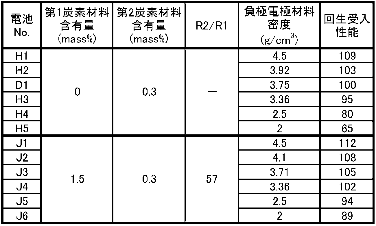
表4および図2に示すように、炭素材料としてカーボンブラックのみを用いた負極板を用いた場合、負極電極材料の密度が3.8g/cm3を超える範囲では、R2/R1比が特定の範囲内である第1炭素材料および第2炭素材料を用いた場合との回生受入性能の差は比較的小さい。これに対し、炭素材料としてカーボンブラックのみを用いた負極板を用いた場合、負極電極材料の密度が3.8g/cm3以下では、R2/R1比が特定の範囲内である第1炭素材料および第2炭素材料を用いた場合と比べて、回生受入性能が低下し易くなる。R2/R1比が特定の範囲内である第1炭素材料および第2炭素材料を用いることで、負極電極材料の密度が3.8g/cm3以下の場合であっても、回生受入性能を向上することができる。これは、R2/R1比が特定の範囲内である第1炭素材料と第2炭素材料とを用いることで、負極電極材料中に導電ネットワークが形成され易くなり、硫酸鉛の還元反応が進行し易くなるためと考えられる。
本発明の一側面に係る鉛蓄電池は、制御弁式および液式の鉛蓄電池に適用可能であり、自動車もしくはバイクなどの始動用の電源や、自然エネルギーの貯蔵、電動車両(フォークリフトなど)などの産業用蓄電装置などの電源として好適に利用できる。
1 鉛蓄電池
2 負極板
2a 負極板の耳部
3 正極板
4 セパレータ
5 正極棚部
6 負極棚部
7 正極柱
8 貫通接続体
9 負極柱
11 極板群
12 電槽
13 隔壁
14 セル室
15 蓋
16 負極端子
17 正極端子
18 液口栓
2 負極板
2a 負極板の耳部
3 正極板
4 セパレータ
5 正極棚部
6 負極棚部
7 正極柱
8 貫通接続体
9 負極柱
11 極板群
12 電槽
13 隔壁
14 セル室
15 蓋
16 負極端子
17 正極端子
18 液口栓
Claims (12)
- 鉛蓄電池であって、
前記鉛蓄電池は、負極板と、正極板と、電解液と、を備え、
前記負極板は、炭素材料を含有する負極電極材料を含み、
前記炭素材料は、32μm以上の粒子径を有する第1炭素材料と、32μm未満の粒子径を有する第2炭素材料と、を含み、
前記第1炭素材料の粉体抵抗R1に対する、前記第2炭素材料の粉体抵抗R2の比:R2/R1が155以下である、鉛蓄電池。 - 前記比:R2/R1が90以下である、請求項1に記載の鉛蓄電池。
- 前記第1炭素材料の比表面積S1に対する、前記第2炭素材料の比表面積S2の比:S2/S1が20以上240以下である、請求項1または2に記載の鉛蓄電池。
- 前記負極電極材料の密度は、2.5g/cm3以上4.2g/cm3以下である、請求項1~3のいずれか1項に記載の鉛蓄電池。
- 前記負極電極材料の密度は、2.5g/cm3以上3.8g/cm3以下である、請求項1~4のいずれか1項に記載の鉛蓄電池。
- 前記比:R2/R1は、10以上である、請求項1~5のいずれか1項に記載の鉛蓄電池。
- 前記負極電極材料中の前記第1炭素材料の含有量は、0.05質量%以上である、請求項1~6のいずれか1項に記載の鉛蓄電池。
- 前記負極電極材料中の前記第1炭素材料の含有量は、3.0質量%以下である、請求項1~7のいずれか1項に記載の鉛蓄電池。
- 前記負極電極材料中の前記第2炭素材料の含有量は、0.03質量%以上である、請求項1~8のいずれか1項に記載の鉛蓄電池。
- 前記負極電極材料中の前記第2炭素材料の含有量は、1.5質量%以下である、請求項1~9のいずれか1項に記載の鉛蓄電池。
- 前記負極電極材料中の前記第2炭素材料の含有量は、0.05質量%以上である、請求項1~10のいずれか1項に記載の鉛蓄電池。
- 前記第1炭素材料は、少なくとも黒鉛を含み、前記第2炭素材料は、少なくともカーボンブラックを含む、請求項1~11のいずれか1項に記載の鉛蓄電池。
Priority Applications (3)
| Application Number | Priority Date | Filing Date | Title |
|---|---|---|---|
| EP18792228.1A EP3588639B1 (en) | 2017-04-28 | 2018-04-24 | Lead acid battery |
| CN201880027228.6A CN110546797B (zh) | 2017-04-28 | 2018-04-24 | 铅蓄电池 |
| JP2019514512A JP7099448B2 (ja) | 2017-04-28 | 2018-04-24 | 鉛蓄電池 |
Applications Claiming Priority (2)
| Application Number | Priority Date | Filing Date | Title |
|---|---|---|---|
| JP2017-090846 | 2017-04-28 | ||
| JP2017090846 | 2017-04-28 |
Publications (1)
| Publication Number | Publication Date |
|---|---|
| WO2018199053A1 true WO2018199053A1 (ja) | 2018-11-01 |
Family
ID=63918930
Family Applications (1)
| Application Number | Title | Priority Date | Filing Date |
|---|---|---|---|
| PCT/JP2018/016522 WO2018199053A1 (ja) | 2017-04-28 | 2018-04-24 | 鉛蓄電池 |
Country Status (4)
| Country | Link |
|---|---|
| EP (1) | EP3588639B1 (ja) |
| JP (1) | JP7099448B2 (ja) |
| CN (1) | CN110546797B (ja) |
| WO (1) | WO2018199053A1 (ja) |
Families Citing this family (1)
| Publication number | Priority date | Publication date | Assignee | Title |
|---|---|---|---|---|
| JP7099450B2 (ja) * | 2017-04-28 | 2022-07-12 | 株式会社Gsユアサ | 鉛蓄電池 |
Citations (8)
| Publication number | Priority date | Publication date | Assignee | Title |
|---|---|---|---|---|
| JP2003142085A (ja) * | 2001-11-02 | 2003-05-16 | Japan Storage Battery Co Ltd | 鉛蓄電池 |
| WO2011090113A1 (ja) * | 2010-01-21 | 2011-07-28 | 株式会社Gsユアサ | 鉛蓄電池用負極板及びその製造方法並びに鉛蓄電池 |
| WO2012017702A1 (ja) * | 2010-08-05 | 2012-02-09 | 新神戸電機株式会社 | 鉛蓄電池 |
| JP2013041848A (ja) * | 2012-10-25 | 2013-02-28 | Shin Kobe Electric Mach Co Ltd | 鉛蓄電池 |
| JP2015128053A (ja) * | 2013-11-29 | 2015-07-09 | 株式会社Gsユアサ | 鉛蓄電池 |
| JP2016152131A (ja) | 2015-02-17 | 2016-08-22 | 株式会社Gsユアサ | 鉛蓄電池 |
| JP2016154131A (ja) * | 2015-02-18 | 2016-08-25 | 株式会社Gsユアサ | 鉛蓄電池 |
| JP2016189260A (ja) | 2015-03-30 | 2016-11-04 | 株式会社Gsユアサ | 鉛蓄電池 |
Family Cites Families (15)
| Publication number | Priority date | Publication date | Assignee | Title |
|---|---|---|---|---|
| JP2004319287A (ja) * | 2003-04-16 | 2004-11-11 | Tdk Corp | リチウムイオン二次電池 |
| JP5797384B2 (ja) * | 2009-08-27 | 2015-10-21 | 古河電池株式会社 | 鉛蓄電池用複合キャパシタ負極板及び鉛蓄電池 |
| JP2011171035A (ja) * | 2010-02-17 | 2011-09-01 | Furukawa Battery Co Ltd:The | 鉛蓄電池用負極板及び鉛蓄電池 |
| MX2012010082A (es) * | 2010-03-01 | 2012-09-12 | Shin Kobe Electric Machinery | Acumulador de acido-plomo. |
| KR20130130751A (ko) * | 2010-12-21 | 2013-12-02 | 신코베덴키 가부시키가이샤 | 연축전지 |
| US8765297B2 (en) * | 2011-01-04 | 2014-07-01 | Exide Technologies | Advanced graphite additive for enhanced cycle-life of lead-acid batteries |
| CN103534864B (zh) * | 2011-05-13 | 2016-11-23 | 新神户电机株式会社 | 铅蓄电池 |
| CN102263250A (zh) * | 2011-06-22 | 2011-11-30 | 吉林汇能科技有限公司 | 铅酸电池复合负极板 |
| EP2770574B1 (en) * | 2011-10-18 | 2016-05-04 | Hitachi Chemical Company, Ltd. | Lead storage battery |
| US10014520B2 (en) * | 2012-10-31 | 2018-07-03 | Exide Technologies Gmbh | Composition that enhances deep cycle performance of valve-regulated lead-acid batteries filled with gel electrolyte |
| CN104650632A (zh) * | 2013-11-25 | 2015-05-27 | 天津蓝天电源公司 | 制作铅酸蓄电池负极板复合涂层用材料 |
| CN103779558A (zh) * | 2014-01-10 | 2014-05-07 | 超威电源有限公司 | 一种铅酸蓄电池负极铅膏 |
| JP6115796B2 (ja) * | 2015-02-18 | 2017-04-19 | 株式会社Gsユアサ | 鉛蓄電池 |
| JP2017054629A (ja) * | 2015-09-08 | 2017-03-16 | 日立化成株式会社 | 鉛蓄電池 |
| CN106099056B (zh) * | 2016-06-17 | 2019-03-29 | 超威电源有限公司 | 一种铅酸电池用石墨烯复合碳及其制备方法 |
-
2018
- 2018-04-24 JP JP2019514512A patent/JP7099448B2/ja active Active
- 2018-04-24 EP EP18792228.1A patent/EP3588639B1/en active Active
- 2018-04-24 CN CN201880027228.6A patent/CN110546797B/zh active Active
- 2018-04-24 WO PCT/JP2018/016522 patent/WO2018199053A1/ja unknown
Patent Citations (8)
| Publication number | Priority date | Publication date | Assignee | Title |
|---|---|---|---|---|
| JP2003142085A (ja) * | 2001-11-02 | 2003-05-16 | Japan Storage Battery Co Ltd | 鉛蓄電池 |
| WO2011090113A1 (ja) * | 2010-01-21 | 2011-07-28 | 株式会社Gsユアサ | 鉛蓄電池用負極板及びその製造方法並びに鉛蓄電池 |
| WO2012017702A1 (ja) * | 2010-08-05 | 2012-02-09 | 新神戸電機株式会社 | 鉛蓄電池 |
| JP2013041848A (ja) * | 2012-10-25 | 2013-02-28 | Shin Kobe Electric Mach Co Ltd | 鉛蓄電池 |
| JP2015128053A (ja) * | 2013-11-29 | 2015-07-09 | 株式会社Gsユアサ | 鉛蓄電池 |
| JP2016152131A (ja) | 2015-02-17 | 2016-08-22 | 株式会社Gsユアサ | 鉛蓄電池 |
| JP2016154131A (ja) * | 2015-02-18 | 2016-08-25 | 株式会社Gsユアサ | 鉛蓄電池 |
| JP2016189260A (ja) | 2015-03-30 | 2016-11-04 | 株式会社Gsユアサ | 鉛蓄電池 |
Non-Patent Citations (1)
| Title |
|---|
| See also references of EP3588639A4 |
Also Published As
| Publication number | Publication date |
|---|---|
| EP3588639B1 (en) | 2020-12-23 |
| JPWO2018199053A1 (ja) | 2020-03-12 |
| JP7099448B2 (ja) | 2022-07-12 |
| EP3588639A1 (en) | 2020-01-01 |
| CN110546797A (zh) | 2019-12-06 |
| CN110546797B (zh) | 2022-06-28 |
| EP3588639A4 (en) | 2020-04-01 |
Similar Documents
| Publication | Publication Date | Title |
|---|---|---|
| JP7355005B2 (ja) | 鉛蓄電池 | |
| JP6973392B2 (ja) | 鉛蓄電池 | |
| JP6756182B2 (ja) | 鉛蓄電池 | |
| JP6766504B2 (ja) | 鉛蓄電池 | |
| JP6954353B2 (ja) | 鉛蓄電池 | |
| WO2020080420A1 (ja) | 鉛蓄電池 | |
| WO2018199053A1 (ja) | 鉛蓄電池 | |
| JP6750377B2 (ja) | 鉛蓄電池 | |
| JP7099450B2 (ja) | 鉛蓄電池 | |
| JP7111099B2 (ja) | 鉛蓄電池 | |
| JP7099452B2 (ja) | 鉛蓄電池 | |
| JP7124828B2 (ja) | 鉛蓄電池 | |
| JP7099449B2 (ja) | 鉛蓄電池 | |
| WO2018199242A1 (ja) | 鉛蓄電池 | |
| JP6900769B2 (ja) | 鉛蓄電池 | |
| JP7099451B2 (ja) | 鉛蓄電池 | |
| WO2020080423A1 (ja) | 鉛蓄電池 | |
| JP2023094127A (ja) | 鉛蓄電池 | |
| JP2024005293A (ja) | 鉛蓄電池 | |
| JP2020102359A (ja) | 鉛蓄電池 |
Legal Events
| Date | Code | Title | Description |
|---|---|---|---|
| 121 | Ep: the epo has been informed by wipo that ep was designated in this application |
Ref document number: 18792228 Country of ref document: EP Kind code of ref document: A1 |
|
| ENP | Entry into the national phase |
Ref document number: 2019514512 Country of ref document: JP Kind code of ref document: A |
|
| ENP | Entry into the national phase |
Ref document number: 2018792228 Country of ref document: EP Effective date: 20190924 |
|
| NENP | Non-entry into the national phase |
Ref country code: DE |