WO2018190028A1 - ステップモータ及び車両用指針計器 - Google Patents
ステップモータ及び車両用指針計器 Download PDFInfo
- Publication number
- WO2018190028A1 WO2018190028A1 PCT/JP2018/008210 JP2018008210W WO2018190028A1 WO 2018190028 A1 WO2018190028 A1 WO 2018190028A1 JP 2018008210 W JP2018008210 W JP 2018008210W WO 2018190028 A1 WO2018190028 A1 WO 2018190028A1
- Authority
- WO
- WIPO (PCT)
- Prior art keywords
- output shaft
- outer peripheral
- peripheral side
- step motor
- radial bearing
- Prior art date
Links
Images


Classifications
-
- B—PERFORMING OPERATIONS; TRANSPORTING
- B60—VEHICLES IN GENERAL
- B60K—ARRANGEMENT OR MOUNTING OF PROPULSION UNITS OR OF TRANSMISSIONS IN VEHICLES; ARRANGEMENT OR MOUNTING OF PLURAL DIVERSE PRIME-MOVERS IN VEHICLES; AUXILIARY DRIVES FOR VEHICLES; INSTRUMENTATION OR DASHBOARDS FOR VEHICLES; ARRANGEMENTS IN CONNECTION WITH COOLING, AIR INTAKE, GAS EXHAUST OR FUEL SUPPLY OF PROPULSION UNITS IN VEHICLES
- B60K35/00—Instruments specially adapted for vehicles; Arrangement of instruments in or on vehicles
- B60K35/60—Instruments characterised by their location or relative disposition in or on vehicles
-
- B—PERFORMING OPERATIONS; TRANSPORTING
- B60—VEHICLES IN GENERAL
- B60K—ARRANGEMENT OR MOUNTING OF PROPULSION UNITS OR OF TRANSMISSIONS IN VEHICLES; ARRANGEMENT OR MOUNTING OF PLURAL DIVERSE PRIME-MOVERS IN VEHICLES; AUXILIARY DRIVES FOR VEHICLES; INSTRUMENTATION OR DASHBOARDS FOR VEHICLES; ARRANGEMENTS IN CONNECTION WITH COOLING, AIR INTAKE, GAS EXHAUST OR FUEL SUPPLY OF PROPULSION UNITS IN VEHICLES
- B60K35/00—Instruments specially adapted for vehicles; Arrangement of instruments in or on vehicles
- B60K35/90—Calibration of instruments, e.g. setting initial or reference parameters; Testing of instruments, e.g. detecting malfunction
-
- G—PHYSICS
- G01—MEASURING; TESTING
- G01D—MEASURING NOT SPECIALLY ADAPTED FOR A SPECIFIC VARIABLE; ARRANGEMENTS FOR MEASURING TWO OR MORE VARIABLES NOT COVERED IN A SINGLE OTHER SUBCLASS; TARIFF METERING APPARATUS; MEASURING OR TESTING NOT OTHERWISE PROVIDED FOR
- G01D13/00—Component parts of indicators for measuring arrangements not specially adapted for a specific variable
- G01D13/22—Pointers, e.g. settable pointer
-
- H—ELECTRICITY
- H02—GENERATION; CONVERSION OR DISTRIBUTION OF ELECTRIC POWER
- H02K—DYNAMO-ELECTRIC MACHINES
- H02K37/00—Motors with rotor rotating step by step and without interrupter or commutator driven by the rotor, e.g. stepping motors
- H02K37/10—Motors with rotor rotating step by step and without interrupter or commutator driven by the rotor, e.g. stepping motors of permanent magnet type
- H02K37/12—Motors with rotor rotating step by step and without interrupter or commutator driven by the rotor, e.g. stepping motors of permanent magnet type with stationary armatures and rotating magnets
- H02K37/14—Motors with rotor rotating step by step and without interrupter or commutator driven by the rotor, e.g. stepping motors of permanent magnet type with stationary armatures and rotating magnets with magnets rotating within the armatures
-
- H—ELECTRICITY
- H02—GENERATION; CONVERSION OR DISTRIBUTION OF ELECTRIC POWER
- H02K—DYNAMO-ELECTRIC MACHINES
- H02K37/00—Motors with rotor rotating step by step and without interrupter or commutator driven by the rotor, e.g. stepping motors
- H02K37/24—Structural association with auxiliary mechanical devices
-
- H—ELECTRICITY
- H02—GENERATION; CONVERSION OR DISTRIBUTION OF ELECTRIC POWER
- H02K—DYNAMO-ELECTRIC MACHINES
- H02K5/00—Casings; Enclosures; Supports
- H02K5/04—Casings or enclosures characterised by the shape, form or construction thereof
- H02K5/10—Casings or enclosures characterised by the shape, form or construction thereof with arrangements for protection from ingress, e.g. water or fingers
-
- H—ELECTRICITY
- H02—GENERATION; CONVERSION OR DISTRIBUTION OF ELECTRIC POWER
- H02K—DYNAMO-ELECTRIC MACHINES
- H02K5/00—Casings; Enclosures; Supports
- H02K5/04—Casings or enclosures characterised by the shape, form or construction thereof
- H02K5/16—Means for supporting bearings, e.g. insulating supports or means for fitting bearings in the bearing-shields
- H02K5/167—Means for supporting bearings, e.g. insulating supports or means for fitting bearings in the bearing-shields using sliding-contact or spherical cap bearings
- H02K5/1675—Means for supporting bearings, e.g. insulating supports or means for fitting bearings in the bearing-shields using sliding-contact or spherical cap bearings radially supporting the rotary shaft at only one end of the rotor
-
- H—ELECTRICITY
- H02—GENERATION; CONVERSION OR DISTRIBUTION OF ELECTRIC POWER
- H02K—DYNAMO-ELECTRIC MACHINES
- H02K7/00—Arrangements for handling mechanical energy structurally associated with dynamo-electric machines, e.g. structural association with mechanical driving motors or auxiliary dynamo-electric machines
- H02K7/10—Structural association with clutches, brakes, gears, pulleys or mechanical starters
- H02K7/116—Structural association with clutches, brakes, gears, pulleys or mechanical starters with gears
-
- B—PERFORMING OPERATIONS; TRANSPORTING
- B60—VEHICLES IN GENERAL
- B60K—ARRANGEMENT OR MOUNTING OF PROPULSION UNITS OR OF TRANSMISSIONS IN VEHICLES; ARRANGEMENT OR MOUNTING OF PLURAL DIVERSE PRIME-MOVERS IN VEHICLES; AUXILIARY DRIVES FOR VEHICLES; INSTRUMENTATION OR DASHBOARDS FOR VEHICLES; ARRANGEMENTS IN CONNECTION WITH COOLING, AIR INTAKE, GAS EXHAUST OR FUEL SUPPLY OF PROPULSION UNITS IN VEHICLES
- B60K2360/00—Indexing scheme associated with groups B60K35/00 or B60K37/00 relating to details of instruments or dashboards
- B60K2360/151—Instrument output devices for configurable output
- B60K2360/1515—Reconfigurable dials
-
- B—PERFORMING OPERATIONS; TRANSPORTING
- B60—VEHICLES IN GENERAL
- B60K—ARRANGEMENT OR MOUNTING OF PROPULSION UNITS OR OF TRANSMISSIONS IN VEHICLES; ARRANGEMENT OR MOUNTING OF PLURAL DIVERSE PRIME-MOVERS IN VEHICLES; AUXILIARY DRIVES FOR VEHICLES; INSTRUMENTATION OR DASHBOARDS FOR VEHICLES; ARRANGEMENTS IN CONNECTION WITH COOLING, AIR INTAKE, GAS EXHAUST OR FUEL SUPPLY OF PROPULSION UNITS IN VEHICLES
- B60K2360/00—Indexing scheme associated with groups B60K35/00 or B60K37/00 relating to details of instruments or dashboards
- B60K2360/60—Structural details of dashboards or instruments
- B60K2360/68—Features of instruments
- B60K2360/698—Pointers of combined instruments
-
- B—PERFORMING OPERATIONS; TRANSPORTING
- B60—VEHICLES IN GENERAL
- B60K—ARRANGEMENT OR MOUNTING OF PROPULSION UNITS OR OF TRANSMISSIONS IN VEHICLES; ARRANGEMENT OR MOUNTING OF PLURAL DIVERSE PRIME-MOVERS IN VEHICLES; AUXILIARY DRIVES FOR VEHICLES; INSTRUMENTATION OR DASHBOARDS FOR VEHICLES; ARRANGEMENTS IN CONNECTION WITH COOLING, AIR INTAKE, GAS EXHAUST OR FUEL SUPPLY OF PROPULSION UNITS IN VEHICLES
- B60K35/00—Instruments specially adapted for vehicles; Arrangement of instruments in or on vehicles
- B60K35/20—Output arrangements, i.e. from vehicle to user, associated with vehicle functions or specially adapted therefor
- B60K35/21—Output arrangements, i.e. from vehicle to user, associated with vehicle functions or specially adapted therefor using visual output, e.g. blinking lights or matrix displays
- B60K35/22—Display screens
- B60K35/223—Flexible displays
Definitions
- the present disclosure relates to a step motor and a vehicle pointer instrument.
- step motors that rotationally drive a rotating body have been widely used.
- the technique disclosed in Patent Document 1 is rotationally driven by a step motor using a rotary pointer that indicates a vehicle state value as a rotating body.
- the rotation shaft of the rotation pointer is inserted into the output gear as the output shaft that is radially supported from the outer peripheral side by the radial bearing of the case in the step motor, and can rotate integrally. Yes.
- One object of the present disclosure is to provide a step motor in which operation failure is suppressed.
- Another object of the present disclosure is to provide a vehicular pointer instrument in which defective indication of a vehicle state value is suppressed.
- a step motor that rotationally drives the rotating body includes: An output shaft that has an insertion hole into which the rotating body is inserted so as to be integrally rotatable on the inner peripheral side from the top of the tip, and outputs a rotational driving force to the rotating body; A radial bearing that radially supports the output shaft from the outer peripheral side; And a cover that protrudes from the radial bearing toward the inner peripheral side and is opposed to the apex at an outer peripheral side with respect to the insertion hole with an axial clearance.
- the labyrinth structure can be constructed between the outside and the edge of the support interface by reducing the axial gap by bringing the cover and the top as close as possible. This makes it difficult for foreign matter to enter the support interface from the outside, and it is possible to suppress malfunctions caused by such foreign matter impeding the rotational drive of the output shaft and the rotating body.
- the vehicle pointer instrument of the present disclosure includes the above-described step motor and a rotation pointer that indicates a vehicle state value as a rotating body.
- the above-described labyrinth structure can be constructed. Therefore, it is difficult for foreign matters such as dust flying in the vehicle to enter the support interface of the output shaft by the radial bearing. Therefore, it is possible to suppress an indication failure of the vehicle state value due to such foreign matter obstructing the rotational driving of the rotation pointer.
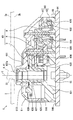
- FIG. 2 is a cross-sectional view showing a vehicular pointer instrument including a step motor according to the first embodiment, and is a cross-sectional view taken along the line II-II in FIG. 1.
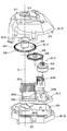
- It is a disassembled perspective view which shows the step motor by 1st embodiment.
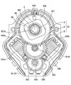
- It is a top view which shows the inside of the step motor by 1st embodiment.
- It is a perspective view which shows the inside of the step motor by 1st embodiment.
- the pointer instrument 1 for a vehicle As shown in FIGS. 1 and 2, the pointer instrument 1 for a vehicle according to the first embodiment is installed on an instrument panel in the vehicle.
- the vehicle pointer instrument 1 includes a display member 2, a rotation pointer 4, and a step motor 6.
- viewing side means the side where the display of the instrument 1 is visually recognized by a passenger on the driver's seat in the vehicle
- anti-viewing side means “the viewing side”. Means the other side.
- the display member 2 is formed by laminating a light-shielding printing layer on a translucent substrate such as polycarbonate resin, and has a flat plate shape as a whole.
- the display surface 2a which is one surface of the display member 2 is arranged toward the viewing side.
- an opening portion of the light-shielding print layer is formed by using numbers and scales arranged in the rotation direction of the rotation pointer 4 as an index 20 in order to display “vehicle state value”.
- the “vehicle state value” in the present embodiment is a vehicle speed value as shown in FIG. 1, but may be a physical quantity related to the vehicle, such as an engine speed.
- a warning lamp 21 for issuing a warning is formed around the rotation shaft 41 of the rotation pointer 4 in the opening portion of the light shielding printing layer in the display member 2.
- the rotation pointer 4 as a “rotating body” is made of a translucent resin material such as acrylic resin, and has a pointer main body 40 and a rotation shaft 41.
- the pointer main body 40 has an elongated needle shape as a whole, and is disposed on the viewing side with respect to the display surface 2 a of the display member 2.
- the pointer main body 40 instructs the “vehicle state value” indicated by the index 20 according to the rotational position by the tip 40a.
- the rotating shaft 41 as a whole has a cylindrical shape extending from the base end 40 b of the pointer main body 40 toward the non-visible side.
- the rotating shaft 41 is inserted into the pointer hole 22 that penetrates between both surfaces 2a and 2b in the display member 2.
- the rotating shaft 41 is connected to the step motor 6 on the side opposite to the visual recognition side from the back surface 2b of the display member 2. Accordingly, the step motor 6 realizes the above instruction by the pointer main body 40 by rotationally driving the rotation pointer 4 around the rotation center line C that is the axis of the rotation shaft 41.
- the step motor 6 is disposed on the counter-viewing side with respect to the back surface 2 b of the display member 2.
- the step motor 6 includes a motor casing 60, a motor main body 63, a motor substrate 64, and light sources 65 and 66.
- the motor casing 60 is formed by combining a pair of case members 61 and 62, and has a hollow shape as a whole.
- Each case member 61, 62 is formed of a light-shielding resin material such as a modified polyphenylene ether resin (m-PPE), and is formed in a cup shape.
- the case members 61 and 62 are coupled to each other by snap-fit fitting in a state where the opening edge portions 610 and 620 are overlapped with each other.
- Each of the case members 61 and 62 has through holes 612 and 622 that pass through the bottom portions 611 and 621 on the rotation center line C of the pointer main body 40.
- the first case member 61 is disposed to face the back surface 2b on the counter-viewing side of the display member 2.
- the second case member 62 is disposed on the opposite side of the first case member 61.
- the motor board 64 is formed by laminating a metal wiring layer on a printed board such as a glass epoxy board, and has a flat plate shape as a whole.
- the motor substrate 64 is disposed on the opposite side of the motor casing 60.
- a mounting surface 640 that is one surface of the motor substrate 64 has a planar shape.
- a motor casing 60 and light sources 65 and 66 are held on the mounting surface 640.
- the motor main body 63 is accommodated in the motor casing 60. Thereby, the motor main body 63 is mounted on the mounting surface 640 of the motor substrate 64 via the motor casing 60.
- the motor body 63 includes a drive source D, a speed reduction mechanism R, and a rotation output mechanism O.
- the drive source D is a combination of the yoke 630, the two-phase coils 631a and 631b, and the magnet rotor 632, and is disposed away from the rotation center line C of the pointer body 40 in the radial direction.
- the yoke 630 is formed in a frame shape from a magnetic metal material such as iron and is fixed to the motor casing 60.
- the yoke 630 has a pair of magnetic poles 630a and 630b protruding to the inner peripheral side.
- An A-phase coil 631a is wound around one magnetic pole 630a, and a B-phase coil 631b is wound around the other magnetic pole 630b.
- the coils 631a and 631b of the phases A and B are electrically connected to the metal wiring layer of the motor board 64 through a through hole that penetrates the second case member 62 of the motor casing 60.
- the magnet rotor 632 is formed in a disk shape from a magnetic metal material such as ferrite, and is disposed on the inner peripheral side of the yoke 630 with a gap between each of the magnetic poles 630a and 630b.
- the magnet rotor 632 is radially supported and thrust supported by the motor casing 60 so as to be rotatable about an axis substantially parallel to the rotation center line C of the pointer main body 40.
- N and S poles as magnetic poles are alternately magnetized in the rotation direction.
- the speed reduction mechanism R is a combination of a magnet gear 634, an idle gear 635, and a pinion gear 636, and is disposed radially away from the rotation center line C of the pointer body 40.
- the magnet gear 634 is made of a hard resin material such as polyacetal resin (POM) and has a spur gear shape.
- the magnet gear 634 is radially supported and thrust supported by the motor casing 60 so as to be integrally rotatable with the magnet rotor 632.
- the idle gear 635 and the pinion gear 636 are integrally formed coaxially with a hard resin material such as polybutylene terephthalate resin (PBT), and each has a spur gear shape.
- PBT polybutylene terephthalate resin
- the idle gear 635 and the pinion gear 636 are radially supported and thrust supported by the motor casing 60 so as to be integrally rotatable about an axis substantially parallel to the rotation center line C of the pointer main body 40.
- the idle gear 635 meshes with the magnet gear 634 to reduce the rotation of the gear 634.
- the rotation output mechanism O is a combination of an output shaft 637, an output gear 638, and a rotation stopper 639, and is disposed on the rotation center line C of the pointer main body 40.
- the output shaft 637, the output gear 638, and the rotation stopper 639 are integrally formed of a hard resin material such as polyacetal resin (POM).
- POM polyacetal resin
- the output shaft 637, the output gear 638, and the rotation stopper 639 are radially supported and thrust supported by the motor casing 60 so as to be integrally rotatable about the rotation center line C of the pointer main body 40.
- the output shaft 637 has a cylindrical shape as a whole.
- the rotation shaft 41 of the rotation pointer 4 is press-fitted coaxially.
- the output shaft 637 rotates around the rotation center line C together with the rotation pointer 4 to output a rotational driving force to the pointer 4.
- the output gear 638 has a spur gear shape extending from the output shaft 637 to the outer peripheral side.
- the output gear 638 meshes with the pinion gear 636 of the speed reduction mechanism R, thereby reducing the rotation of the gear 636.
- the rotation stopper 639 has a protruding piece shape protruding from the output gear 638 to the viewing side.
- the rotation stopper 639 is provided so as to be locked by a fixed stopper of the motor casing 60 at the limit positions on both sides that determine the rotation range of the rotation pointer 4. As a result, even if a rotational driving force is applied from the rotation output mechanism O to the rotation pointer 4, the rotation of the pointer 4 outside the rotation range is limited.
- the rotating body illumination light source 65 is disposed on the rotation center line C of the pointer main body 40 in the through hole 622 of the second case member 62, and is mounted on the mounting surface 640 of the motor board 64. .
- the rotating body illumination light source 65 is mainly composed of LEDs (Light-Emitting-Diodes) and is electrically connected to the metal wiring layer of the motor board 64.
- the rotating body illumination light source 65 emits light when energized from an external control circuit through the metal wiring layer.
- the light emitted from the rotating body illumination light source 65 passes through the through hole 622 of the second case member 62 and the center hole 637a of the output shaft 637 and is incident on the rotating shaft 41 of the rotating pointer 4, thereby Guided to the pointer body 40. Thereby, the rotation pointer 4 is illuminated through the motor main body 63, so that the pointer main body 40 is visually recognized in a light-emitting state.
- a plurality of display illumination light sources 66 are arranged around the second case member 62 and mounted on the mounting surface 640 of the motor board 64.
- Each display illumination light source 66 is mainly composed of LEDs, and is electrically connected to the metal wiring layer of the motor board 64.
- Each display illumination light source 66 emits light when energized at the time of a necessary warning from an external control circuit via a metal wiring layer. The light emitted from the display illumination light source 66 passes through the periphery of the motor casing 60 and enters the display member 2. As a result, the display member 2 is directly illuminated so that the warning lamp 21 emits light when a necessary warning is issued.
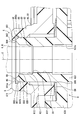
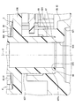
- the foreign substance intrusion suppression structure 8 and the related structure of the first embodiment shown in FIGS. 6 and 7 will be described in detail.
- the axial direction along the rotation center line C shown in FIGS. 6 and 7, the radial direction substantially perpendicular to the same line C, and the circumferential direction around the same line C are simply referred to as the axial direction and the radial direction, respectively. And the circumferential direction.
- the tip 637 b of the output shaft 637 is inserted into the through hole 612 of the first case member 61 in the motor casing 60.
- the tip 637b of the output shaft 637 forms a top 80 by its end face.
- the top portion 80 of the present embodiment has an annular planar shape having a width in the radial direction and continuous in the circumferential direction.
- the output shaft 637 has an insertion hole portion 81 and a guide hole portion 82 which are formed by a part in the axial direction of the central hole 637a that opens to the top portion 80 of the tip 637b.
- the insertion hole 81 is provided in a predetermined axial range that is spaced away from the top 80 of the output shaft 637 toward the non-viewing side.
- the insertion hole portion 81 has a cylindrical hole shape that extends straight along the axial direction.
- the inner diameter of the insertion hole 81 is set to be smaller than the inner diameter of the inner peripheral edge 800 at the top 80.
- a part of the rotation pointer 4 in the axial direction of the rotary pointer 4 is coaxially inserted into a part of the insertion hole 81 in the axial direction.
- a rotating shaft 41 formed with a larger diameter than the hole portion 81 before insertion is inserted with a press-fitting allowance. That is, the rotation shaft 41 is press-fitted and fixed in the insertion hole 81.
- the rotation pointer 4 can rotate integrally with the output shaft 637.
- the guide hole 82 is provided with a stepped inner peripheral surface in a predetermined axial direction range from the top 80 to the insertion hole 81 in the output shaft 637.
- the guide hole portion 82 forms inner peripheral taper portions 820 and 822 and an inner peripheral straight portion 821.
- the first inner circumferential taper portion 820 has a tapered hole shape (that is, a conical hole shape) that gradually decreases in diameter in the axial direction from the inner circumferential side edge portion 800 of the top portion 80 to the inner circumferential side insertion hole portion 81. ).
- the inner peripheral slate portion 821 has a cylindrical hole shape that extends straight from the opposite end of the first inner peripheral tapered portion 820 (that is, the inner peripheral edge) along the axial direction.
- the second inner peripheral tapered portion 822 has a tapered hole shape (that is, a conical hole shape) that gradually decreases in diameter in the axial direction from the counter-viewing side end of the inner peripheral straight portion 821 to the insertion hole portion 81 on the inner peripheral side.
- a tapered hole shape that is, a conical hole shape
- the output shaft 637 further includes an outer peripheral slate portion 83 and an outer peripheral tapered portion 84 formed by a part in the axial direction on the outer peripheral side of the top portion 80 of the tip 637b.
- the outer peripheral slate part 83 is provided in a predetermined axial range separated from the top part 80 on the output shaft 637 on the side opposite to the visual recognition side.
- the outer peripheral slate part 83 has a cylindrical surface shape extending straight along the axial direction.
- the outer diameter of the outer peripheral slate part 83 is set to be larger than the outer diameter of the outer peripheral side edge part 801 in the top part 80.
- the outer peripheral taper portion 84 is provided in a predetermined axial range from the top 80 to the outer peripheral slate portion 83 on the output shaft 637.
- the outer peripheral taper portion 84 has a tapered surface shape (that is, a conical surface shape) that gradually increases in diameter in the axial direction from the outer peripheral side edge portion 801 of the top portion 80 to the support interface 850 by the radial bearing 85 on the outer peripheral side.
- the first case member 61 of the motor casing 60 has a radial bearing 85 and a cover 86 formed by a part of each of the through holes 612 coaxially surrounding the output shaft 637.
- the radial bearing 85 is provided in a predetermined axial range that is spaced away from the outer surface 611a of the bottom 611 in the first case member 61 toward the non-viewing side.
- the radial bearing 85 has a cylindrical hole shape that extends straight along the axial direction on the inner peripheral surface.
- the inner diameter of the radial bearing 85 is set to be smaller than the inner diameter of the portion located on both sides in the axial direction of the bearing 85 in the through hole 612. In the entire axial direction of the radial bearing 85, a part of the outer peripheral slate portion 83 in the axial direction closer to the viewing side than the output gear 638 is coaxially inserted.
- an outer peripheral slate portion 83 having a slightly smaller diameter than the bearing 85 is fitted on the inner peripheral side of the radial bearing 85 so as to be capable of relative sliding.
- the radial bearing 85 forms a support interface 850 with the shaft 637 by radially supporting the output shaft 637 from the outer peripheral side.
- the cover 86 is provided in a predetermined axial range from the outer surface 611 a of the bottom 611 to the radial bearing 85 in the first case member 61.
- the cover 86 has an annular disk shape that protrudes from the radial bearing 85 toward the inner peripheral side and is continuous in the circumferential direction.
- the cover 86 of this embodiment is formed integrally with the radial bearing 85. Further, the cover 86 of this embodiment is on the outer peripheral side of the insertion hole portion 81 of the output shaft 637 and the first inner peripheral tapered portion 820 of the guide hole portion 82 and on the inner peripheral side of the outer peripheral tapered portion 84 of the coaxial 637.
- the inner peripheral side edge 862 on the protruding side is positioned in the radial direction range.
- the inner peripheral edge 862 of the cover 86 is arranged in a radial range that is on the outer peripheral side of the inner peripheral side edge 800 of the top 80 and on the inner peripheral side of the outer peripheral edge 801 of the top 80. .
- the cover 86 is opposed to the top 80 and the outer peripheral taper portion 84 of the output shaft 637 with axial gaps 860 and 861 on the outer peripheral side from the insertion hole portion 81 and the first inner peripheral taper portion 820, respectively. Yes.
- the edge 850 a on the top 80 side of the support interface 850 formed by the radial bearing 85 and the output shaft 637 and the outside of the motor casing 60 In between, an axial width and a radial width are provided that allow the labyrinth structure to be constructed. Therefore, in particular, the axial width of the axial gap 860 is set to be smaller than the size of the foreign matter that is assumed to enter the support interface 850 as foreign matter such as dust flying in the vehicle. As a result, a labyrinth structure effective for restricting entry of foreign matter into the support interface 850 is constructed between the edge portion 850 a of the support interface 850 and the outside of the motor casing 60.
- the second case member 62 of the motor casing 60 has a thrust bearing 87 formed by a part in the axial direction of the cylindrical portion 624 that protrudes from the bottom portion 621 toward the viewing side.
- the thrust bearing 87 is provided in the second case member 62 within a predetermined axial range from the bottom 621.
- the thrust bearing 87 has a cylindrical shape with a bottom that extends coaxially with the through hole 622 of the second case member 62 and extends straight along the axial direction on the inner peripheral surface.
- the inner diameter of the thrust bearing 87 is set larger than the inner diameter of the through hole 622. Accordingly, the bottom surface 870 of the thrust bearing 87 has an annular planar shape.
- the thrust bearing 87 supports the output shaft 637 radially from the outer peripheral side and thrust-supports the coaxial 637 from the side opposite to the top 80 in the axial direction.
- the rotation output mechanism O is further provided with a biasing member 89 in addition to the set of the output shaft 637, the output gear 638, and the rotation stopper 639.
- the urging member 89 is made of an elastic metal material such as stainless steel (SUS) and has a leaf spring shape.
- the biasing member 89 has a center hole 890 having a cylindrical hole shape, and is arranged coaxially with the outer peripheral slate portion 83 of the output shaft 637.
- the center hole 890 of the urging member 89 surrounds the outer peripheral slate portion 83 from the outer peripheral side between the radial bearing 85 and the output gear 638.
- the urging member 89 is elastically deformed in a state where the urging member 89 can rotate integrally with the output gear 638 by being sandwiched and compressed by the bottom 611 of the first case member 61 and the output gear 638.
- the urging member 89 urges the output shaft 637 toward the counter-viewing side, which is the opposite side in the axial direction from the top 80, regardless of the rotational positions of the output gear 638 and the output shaft 637.
- the insertion hole portion 81 into which the rotary pointer 4 is inserted so as to be integrally rotatable on the inner peripheral side of the top portion 80 of the tip 637b.
- the cover 86 projecting from the radial bearing 85 to the inner peripheral side is opposed to the top 80 with an axial gap 860 therebetween.
- the labyrinth structure can be constructed between the outside and the edge portion 850a of the support interface 850 by reducing the axial gap 860 by bringing the cover 86 and the top portion 80 as close as possible.
- the rotation shaft 41 of the rotary pointer 4 is pressed against the first inner circumferential taper portion 820 whose diameter is reduced as the output shaft 637 approaches the insertion hole 81 on the inner circumferential side from the top 80.
- the shaft 41 can be guided toward the insertion hole 81.
- the facing portion where the axial gap 860 between the cover 86 and the top 80 is opened is on the outer peripheral side with respect to the first inner peripheral tapered portion 820, the guiding action of the rotation pointer 4 by the first inner peripheral tapered portion 820 is as follows. It is difficult to be blocked by the cover 86. Therefore, it is possible to obtain an effect of suppressing operation failure after manufacturing while ensuring the workability of inserting the rotary pointer 4 into the insertion hole 81 during manufacturing.
- the top portion 80 having a radial width on the output shaft 637 faces the cover 86, a large axial gap 860 between the top portion 80 and the cover 86 is ensured in the radial direction to prevent foreign matter. It is possible to construct a labyrinth structure with excellent intrusion control function. Therefore, it is possible to increase the effect of suppressing malfunction.
- the outer peripheral taper portion 84 whose diameter increases as it approaches the support interface 850 by the radial bearing 85 on the outer peripheral side in the output shaft 637 functions as a chamfer. 637 is difficult to break during manufacture.
- the axial gap 861 between the outer peripheral taper portion 84 and the cover 86 on the outer peripheral side is larger than the axial clearance 860 between the top portion 80 and the cover 86 on the inner peripheral side, but the latter axial gap 860 is reduced.
- the output shaft 637 thrust-supported from the side opposite to the top 80 by the thrust bearing 87 is urged to the opposite side by the urging member 89 surrounding itself from the outer peripheral side.
- a labyrinth structure effective for restricting the entry of foreign matter can be used as the rotational position of the output shaft 637. Regardless, it can be secured. Therefore, it becomes possible to continuously exhibit the effect of suppressing malfunction.
- manufacturing tolerances are less likely to occur in the axial position of the cover 86 that is integrally formed with the radial bearing 85, so that a labyrinth structure that is effective in restricting entry of foreign matter is guaranteed regardless of the product. It becomes easy to do. Therefore, it is possible to obtain an effect of suppressing operation failure after manufacturing while increasing the production yield at the time of manufacturing.
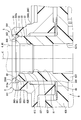
- the second embodiment is a modification of the first embodiment.
- the cover 2086 is formed separately from the radial bearing 85 by a light-shielding resin material such as a modified polyphenylene ether resin (m-PPE), and an adhesive or the like. Is attached to the bearing 85.
- a light-shielding resin material such as a modified polyphenylene ether resin (m-PPE), and an adhesive or the like. Is attached to the bearing 85.
- a labyrinth structure in which the cover 86 is opposed to the top 80 can be easily constructed by mounting the cover 86 formed separately from the radial bearing 85 on the bearing 85. Can do. According to this, it is possible to obtain the effect of suppressing malfunction while simplifying the production equipment required for the complicated shape in which the cover 86 protrudes from the radial bearing 85 to the inner peripheral side.
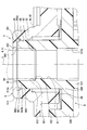
- a sharp apex 1080 having substantially no width in the radial direction may be employed as shown in FIG.
- the cover 86 faces the sharp apex 1080 with a gap 860 in the axial direction.
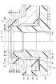
- the inner peripheral slate portion 821 may be extended from the inner peripheral side edge portion 800 of the top portion 80 without providing the first inner peripheral tapered portion 820 as shown in FIG.
- the inner circumferential edge 862 of the cover 86 projects as far as possible toward the inner circumferential side, so that the axial gap 860 is largely secured in the radial direction.
- the inner peripheral side of the cover 86 is in a radial range that is on the outer peripheral side of the insertion hole 81 of the output shaft 637 and on the inner peripheral side of the top 80 of the coaxial 637.
- An edge 1862 may be located.
- the radial direction of the guide hole portion 82 that is on the outer peripheral side of the inner peripheral slate portion 821 and the second inner peripheral tapered portion 822 and on the inner peripheral side of the top portion 80.
- the inner peripheral edge 1862 of the cover 86 is disposed in the range.
- the outer periphery taper part 84 does not need to be provided.
- the urging member 89 may not be provided.
- the present disclosure may be applied to a device other than the pointer instrument 1 for a vehicle such as a head-up display (HUD), and the “rotary body” of the device may be rotationally driven by the step motor 6.
- HUD head-up display
Landscapes
- Engineering & Computer Science (AREA)
- Power Engineering (AREA)
- Chemical & Material Sciences (AREA)
- Combustion & Propulsion (AREA)
- Transportation (AREA)
- Mechanical Engineering (AREA)
- Physics & Mathematics (AREA)
- General Physics & Mathematics (AREA)
- Instrument Panels (AREA)
- Connection Of Motors, Electrical Generators, Mechanical Devices, And The Like (AREA)
- Motor Or Generator Frames (AREA)
Priority Applications (4)
| Application Number | Priority Date | Filing Date | Title |
|---|---|---|---|
| DE112018002015.0T DE112018002015B4 (de) | 2017-04-13 | 2018-03-05 | Schrittmotor und anzeigeinstrument für fahrzeuge |
| CN201880004954.6A CN110073581B (zh) | 2017-04-13 | 2018-03-05 | 步进马达以及车辆用指针仪表 |
| KR1020197021183A KR102177151B1 (ko) | 2017-04-13 | 2018-03-05 | 스텝 모터 및 차량용 지침 계기 |
| US16/524,828 US11440411B2 (en) | 2017-04-13 | 2019-07-29 | Step motor and indicator instrument for vehicle |
Applications Claiming Priority (2)
| Application Number | Priority Date | Filing Date | Title |
|---|---|---|---|
| JP2017-079883 | 2017-04-13 | ||
| JP2017079883A JP6733593B2 (ja) | 2017-04-13 | 2017-04-13 | ステップモータ及び車両用指針計器 |
Related Child Applications (1)
| Application Number | Title | Priority Date | Filing Date |
|---|---|---|---|
| US16/524,828 Continuation US11440411B2 (en) | 2017-04-13 | 2019-07-29 | Step motor and indicator instrument for vehicle |
Publications (1)
| Publication Number | Publication Date |
|---|---|
| WO2018190028A1 true WO2018190028A1 (ja) | 2018-10-18 |
Family
ID=63792878
Family Applications (1)
| Application Number | Title | Priority Date | Filing Date |
|---|---|---|---|
| PCT/JP2018/008210 WO2018190028A1 (ja) | 2017-04-13 | 2018-03-05 | ステップモータ及び車両用指針計器 |
Country Status (6)
Cited By (1)
| Publication number | Priority date | Publication date | Assignee | Title |
|---|---|---|---|---|
| US11440411B2 (en) * | 2017-04-13 | 2022-09-13 | Denso Corporation | Step motor and indicator instrument for vehicle |
Families Citing this family (6)
| Publication number | Priority date | Publication date | Assignee | Title |
|---|---|---|---|---|
| JP7197769B2 (ja) * | 2018-09-27 | 2022-12-28 | サミー株式会社 | 遊技機 |
| JP7197766B2 (ja) * | 2018-09-27 | 2022-12-28 | サミー株式会社 | 遊技機 |
| JP7197767B2 (ja) * | 2018-09-27 | 2022-12-28 | サミー株式会社 | 遊技機 |
| JP7197770B2 (ja) * | 2018-09-27 | 2022-12-28 | サミー株式会社 | 遊技機 |
| JP7197771B2 (ja) * | 2018-09-27 | 2022-12-28 | サミー株式会社 | 遊技機 |
| JP7566297B2 (ja) * | 2020-03-31 | 2024-10-15 | 伊東電機株式会社 | モータ用制御装置 |
Citations (5)
| Publication number | Priority date | Publication date | Assignee | Title |
|---|---|---|---|---|
| JP2007151355A (ja) * | 2005-11-30 | 2007-06-14 | Nippon Seiki Co Ltd | マグネットロータおよびそのマグネットロータを備えた可動磁石式計器、そのマグネットロータを備えたステッピングモータ |
| JP2010214573A (ja) * | 2009-03-19 | 2010-09-30 | Seiko Epson Corp | ロボットおよびその制御方法 |
| WO2012035926A1 (ja) * | 2010-09-15 | 2012-03-22 | 日本精機株式会社 | 計器用駆動装置 |
| JP2016086556A (ja) * | 2014-10-27 | 2016-05-19 | 日本電産サンキョー株式会社 | ギアードモータおよび指針式表示装置 |
| JP2017022891A (ja) * | 2015-07-13 | 2017-01-26 | 日本電産サンキョー株式会社 | モータ、モータ装置および指針式表示装置 |
Family Cites Families (27)
| Publication number | Priority date | Publication date | Assignee | Title |
|---|---|---|---|---|
| AR247045A1 (es) * | 1988-03-03 | 1994-10-31 | Emerson Electric Co | Conjunto de terminal hermetico. |
| DE69425119T2 (de) * | 1993-12-14 | 2001-02-15 | Hitachi, Ltd. | Aufzeichnungsplattengerät und rotierende Halterungsstruktur dafür |
| JP3246356B2 (ja) * | 1996-01-29 | 2002-01-15 | 株式会社デンソー | 面軸受け及びこの面軸受けを具備する指示計器 |
| KR20010038339A (ko) * | 1999-10-25 | 2001-05-15 | 이형도 | 스핀들 모터 |
| JP2001317970A (ja) | 2000-05-10 | 2001-11-16 | Yazaki Corp | ステッピングモータ及び該ステッピングモータを用いた計器並びに該計器の組み立て方法 |
| ITPD20010268A1 (it) * | 2001-11-20 | 2003-05-20 | Askoll Holding Srl | Supporto di rotazione perfezionato particolarmente per rotori di motori elettrici di pompe. |
| JP2003254797A (ja) | 2002-03-01 | 2003-09-10 | Denso Corp | 指針計器用回動内機 |
| FR2901605B1 (fr) * | 2006-05-24 | 2008-08-08 | Sonceboz Sa Suisse | Module indicateur de tableau de bord |
| CN101153632B (zh) * | 2006-09-27 | 2010-05-26 | 富准精密工业(深圳)有限公司 | 保油轴承结构与风扇马达 |
| JP5247280B2 (ja) * | 2008-07-23 | 2013-07-24 | 矢崎総業株式会社 | 指針照明構造 |
| JP5255480B2 (ja) | 2009-02-18 | 2013-08-07 | 矢崎総業株式会社 | 指示計器用の駆動装置 |
| JP2010226924A (ja) * | 2009-03-25 | 2010-10-07 | Tokyo Micro:Kk | 空芯ステッピングモータ及び軸支持構造 |
| JP5545946B2 (ja) | 2009-11-09 | 2014-07-09 | 矢崎総業株式会社 | メータ装置の照明構造 |
| JP2011172371A (ja) * | 2010-02-18 | 2011-09-01 | Nippon Densan Corp | モータ、ディスク駆動装置、およびモータの製造方法 |
| JP5345099B2 (ja) * | 2010-04-09 | 2013-11-20 | 矢崎総業株式会社 | 計器ユニット |
| CN201674309U (zh) * | 2010-06-12 | 2010-12-15 | 金龙机电股份有限公司 | 一种用于微型马达的端盖和端盖组件 |
| JP5735851B2 (ja) * | 2011-04-28 | 2015-06-17 | 矢崎総業株式会社 | 指針装置及びこれを取り付けたメータ装置 |
| FR2982715B1 (fr) * | 2011-11-14 | 2013-11-15 | Moving Magnet Tech | Module indicateur pour tableau de bord a mouvement fluide |
| KR101250624B1 (ko) * | 2011-11-17 | 2013-04-03 | 삼성전기주식회사 | 유체 동압 베어링 어셈블리 및 이를 포함하는 모터 |
| JP6076670B2 (ja) | 2012-10-03 | 2017-02-08 | 東京パーツ工業株式会社 | モータ |
| CN203616124U (zh) * | 2013-11-29 | 2014-05-28 | 四川禧鑫机床制造有限责任公司 | 数控锥齿轮检查机的从动箱 |
| JP6422755B2 (ja) * | 2013-12-11 | 2018-11-14 | Ntn株式会社 | 流体動圧軸受装置およびこれを備えるモータ |
| JP2017079883A (ja) | 2015-10-23 | 2017-05-18 | 富士通株式会社 | 視線検出システム、視線検出方法、および視線検出プログラム |
| JP6673282B2 (ja) * | 2017-04-13 | 2020-03-25 | 株式会社デンソー | ステップモータ及び車両用指針計器 |
| JP6733593B2 (ja) * | 2017-04-13 | 2020-08-05 | 株式会社デンソー | ステップモータ及び車両用指針計器 |
| JP6652102B2 (ja) * | 2017-04-13 | 2020-02-19 | 株式会社デンソー | ステップモータ及び車両用指針計器 |
| JP6717279B2 (ja) * | 2017-09-28 | 2020-07-01 | 株式会社デンソー | 車両用指針計器 |
-
2017
- 2017-04-13 JP JP2017079883A patent/JP6733593B2/ja active Active
-
2018
- 2018-03-05 KR KR1020197021183A patent/KR102177151B1/ko not_active Expired - Fee Related
- 2018-03-05 CN CN201880004954.6A patent/CN110073581B/zh active Active
- 2018-03-05 WO PCT/JP2018/008210 patent/WO2018190028A1/ja active Application Filing
- 2018-03-05 DE DE112018002015.0T patent/DE112018002015B4/de active Active
-
2019
- 2019-07-29 US US16/524,828 patent/US11440411B2/en active Active
Patent Citations (5)
| Publication number | Priority date | Publication date | Assignee | Title |
|---|---|---|---|---|
| JP2007151355A (ja) * | 2005-11-30 | 2007-06-14 | Nippon Seiki Co Ltd | マグネットロータおよびそのマグネットロータを備えた可動磁石式計器、そのマグネットロータを備えたステッピングモータ |
| JP2010214573A (ja) * | 2009-03-19 | 2010-09-30 | Seiko Epson Corp | ロボットおよびその制御方法 |
| WO2012035926A1 (ja) * | 2010-09-15 | 2012-03-22 | 日本精機株式会社 | 計器用駆動装置 |
| JP2016086556A (ja) * | 2014-10-27 | 2016-05-19 | 日本電産サンキョー株式会社 | ギアードモータおよび指針式表示装置 |
| JP2017022891A (ja) * | 2015-07-13 | 2017-01-26 | 日本電産サンキョー株式会社 | モータ、モータ装置および指針式表示装置 |
Cited By (1)
| Publication number | Priority date | Publication date | Assignee | Title |
|---|---|---|---|---|
| US11440411B2 (en) * | 2017-04-13 | 2022-09-13 | Denso Corporation | Step motor and indicator instrument for vehicle |
Also Published As
| Publication number | Publication date |
|---|---|
| DE112018002015T5 (de) | 2020-01-09 |
| JP6733593B2 (ja) | 2020-08-05 |
| US20190381886A1 (en) | 2019-12-19 |
| US11440411B2 (en) | 2022-09-13 |
| DE112018002015B4 (de) | 2024-10-02 |
| KR20190094453A (ko) | 2019-08-13 |
| KR102177151B1 (ko) | 2020-11-10 |
| CN110073581B (zh) | 2021-09-10 |
| JP2018182911A (ja) | 2018-11-15 |
| CN110073581A (zh) | 2019-07-30 |
Similar Documents
| Publication | Publication Date | Title |
|---|---|---|
| JP6733593B2 (ja) | ステップモータ及び車両用指針計器 | |
| KR102178093B1 (ko) | 스텝 모터 및 차량용 지침 계기 | |
| JP4145083B2 (ja) | モータおよび計器 | |
| JP6016273B2 (ja) | ロータリーアクチュエータ及びそれを用いた操作感触付与型入力装置 | |
| JP2013160356A (ja) | 電磁ブレーキ装置及びこれを用いた力覚付与型回転入力装置 | |
| JP2010019619A (ja) | 表示装置 | |
| US11274730B2 (en) | Step motor and indicator instrument for vehicle | |
| US20100102659A1 (en) | Motor for driving color wheel | |
| US11639104B2 (en) | Indicator instrument for vehicle | |
| JP2011223776A (ja) | 計器ユニット | |
| JP2009261149A (ja) | ブラシレスモータ | |
| JP5594823B2 (ja) | 指針ユニット | |
| JP2021067536A (ja) | 回転駆動装置及び車両用指針計器 | |
| JP2015102468A (ja) | 計器 | |
| JP5360998B2 (ja) | メータ装置の指針組付構造 | |
| CN108983415B (zh) | 旋转驱动装置 | |
| JP2021078174A (ja) | 回転駆動装置及び車両用指針計器 | |
| JP5437892B2 (ja) | 計器ユニット | |
| JP2010151541A (ja) | 表示装置 | |
| JP2014173899A (ja) | 計器装置の指針構造 | |
| JP2005351670A (ja) | 指針計器 | |
| JPH0738973U (ja) | クロスコイル形指示計器ユニット | |
| JP2000161999A (ja) | ステッピングモータ式計器 |
Legal Events
| Date | Code | Title | Description |
|---|---|---|---|
| 121 | Ep: the epo has been informed by wipo that ep was designated in this application |
Ref document number: 18784122 Country of ref document: EP Kind code of ref document: A1 |
|
| ENP | Entry into the national phase |
Ref document number: 20197021183 Country of ref document: KR Kind code of ref document: A |
|
| 122 | Ep: pct application non-entry in european phase |
Ref document number: 18784122 Country of ref document: EP Kind code of ref document: A1 |