WO2018186206A1 - 車両用シート - Google Patents
車両用シート Download PDFInfo
- Publication number
- WO2018186206A1 WO2018186206A1 PCT/JP2018/011654 JP2018011654W WO2018186206A1 WO 2018186206 A1 WO2018186206 A1 WO 2018186206A1 JP 2018011654 W JP2018011654 W JP 2018011654W WO 2018186206 A1 WO2018186206 A1 WO 2018186206A1
- Authority
- WO
- WIPO (PCT)
- Prior art keywords
- holding member
- position holding
- torsion bar
- vehicle seat
- engaging
- Prior art date
- Legal status (The legal status is an assumption and is not a legal conclusion. Google has not performed a legal analysis and makes no representation as to the accuracy of the status listed.)
- Ceased
Links
Images






Classifications
-
- B—PERFORMING OPERATIONS; TRANSPORTING
- B60—VEHICLES IN GENERAL
- B60N—SEATS SPECIALLY ADAPTED FOR VEHICLES; VEHICLE PASSENGER ACCOMMODATION NOT OTHERWISE PROVIDED FOR
- B60N2/00—Seats specially adapted for vehicles; Arrangement or mounting of seats in vehicles
- B60N2/02—Seats specially adapted for vehicles; Arrangement or mounting of seats in vehicles the seat or part thereof being movable, e.g. adjustable
- B60N2/04—Seats specially adapted for vehicles; Arrangement or mounting of seats in vehicles the seat or part thereof being movable, e.g. adjustable the whole seat being movable
- B60N2/16—Seats specially adapted for vehicles; Arrangement or mounting of seats in vehicles the seat or part thereof being movable, e.g. adjustable the whole seat being movable height-adjustable
- B60N2/1605—Seats specially adapted for vehicles; Arrangement or mounting of seats in vehicles the seat or part thereof being movable, e.g. adjustable the whole seat being movable height-adjustable characterised by the cinematic
- B60N2/161—Rods
-
- B—PERFORMING OPERATIONS; TRANSPORTING
- B60—VEHICLES IN GENERAL
- B60N—SEATS SPECIALLY ADAPTED FOR VEHICLES; VEHICLE PASSENGER ACCOMMODATION NOT OTHERWISE PROVIDED FOR
- B60N2/00—Seats specially adapted for vehicles; Arrangement or mounting of seats in vehicles
- B60N2/02—Seats specially adapted for vehicles; Arrangement or mounting of seats in vehicles the seat or part thereof being movable, e.g. adjustable
- B60N2/0224—Non-manual adjustments, e.g. with electrical operation
- B60N2/02246—Electric motors therefor
-
- B—PERFORMING OPERATIONS; TRANSPORTING
- B60—VEHICLES IN GENERAL
- B60N—SEATS SPECIALLY ADAPTED FOR VEHICLES; VEHICLE PASSENGER ACCOMMODATION NOT OTHERWISE PROVIDED FOR
- B60N2/00—Seats specially adapted for vehicles; Arrangement or mounting of seats in vehicles
- B60N2/02—Seats specially adapted for vehicles; Arrangement or mounting of seats in vehicles the seat or part thereof being movable, e.g. adjustable
- B60N2/04—Seats specially adapted for vehicles; Arrangement or mounting of seats in vehicles the seat or part thereof being movable, e.g. adjustable the whole seat being movable
- B60N2/16—Seats specially adapted for vehicles; Arrangement or mounting of seats in vehicles the seat or part thereof being movable, e.g. adjustable the whole seat being movable height-adjustable
- B60N2/1675—Seats specially adapted for vehicles; Arrangement or mounting of seats in vehicles the seat or part thereof being movable, e.g. adjustable the whole seat being movable height-adjustable with weight compensating means
Definitions
- This disclosure relates to a vehicle seat provided with a seat cushion that can be adjusted in height.
- Patent Document 1 in a seat cushion that moves up and down by a link, a torsion bar is arranged in a pipe that connects a pair of left and right links, and the raising of the seat cushion is assisted by the urging force of the torsion bar. Is described. On one end side of the torsion bar and the pipe, a position holding member for holding the torsion bar is fitted into the inner hole of the pipe in order to align the axial center of the torsion bar with the central axis of the pipe.
- Patent Document 2 describes that a cylindrical position holding member is composed of two semi-cylindrical parts.
- JP 2007-230253 A Japanese Patent Laying-Open No. 2015-3577
- the conventional position holding member may rotate relative to the torsion bar, and the position of the position holding member that receives the lateral force from the torsion bar may change. For this reason, the position holding member needs to secure strength over a wide range of angles, which hinders downsizing and weight reduction of the position holding member.
- the present invention provides a vehicle seat provided with a position holding member that does not rotate relative to a torsion bar in the vehicle seat provided with the seat cushion that can be adjusted in height.
- Another object of the present invention is to provide a position holding member that can be easily assembled.
- a vehicle seat (1) includes a base member (2) supported by a vehicle body, a cushion frame (5) constituting a frame of a seat cushion (3), and the base A link mechanism (6) for supporting the cushion frame to be vertically displaceable with respect to a member; a drive mechanism (7) for driving the cushion frame in the vertical direction via the link mechanism; and the cushion frame upward.
- Vehicle comprising said seat cushion with adjustable height comprising a first part (12) and a torsion bar (14) coupled to a second part (8) for relative rotation
- the torsion bar extends in a direction crossing the shaft portion at least partially on the second end side, and the second torsion bar extends in the left-right direction.
- the first portion of the torsion bar supports the first end of the torsion bar in a non-rotatable manner and the second end side of the shaft portion of the torsion bar.
- a position holding member (24, 41) for suppressing displacement of the axis of the torsion bar, and the position holding member is rotatably supported with respect to the first portion, It has a main-body part (25, 42) containing the through-hole (27) which penetrates a axial part, and an engaging part (26, 43) engaged so that it may rotate integrally with the said extension part, It is characterized by the above-mentioned.
- the position holding member does not rotate about the axis with respect to the torsion bar, but rotates with respect to the first portion. Therefore, the position where the lateral force of the torsion bar on the position holding member is applied is constant. It is sufficient for the position holding member to ensure the strength to withstand lateral force in a narrow angle range.
- the vehicle seat has a connection pipe (12) in which either one of the cushion frame and the link mechanism is rotatable with respect to the other in the above configuration.
- the connecting pipe constitutes the first portion, and the main body of the position holding member has a cylindrical contour and is rotatably received in the inner hole (13) of the connecting pipe. It is characterized by.
- the first portion can have a simple structure.
- the engagement portion (26) of the position holding member (24) protrudes from the main body portion (25) in any of the above configurations.
- the engaging portion (43) of the position holding member (41) has a pair of engaging claws (44) protruding from the main body portion (42) and holding the extension portion.
- the engaging portion can have a simple structure.
- the engaging claw locks the extension portion so as to overhang, and is positioned above the engaging convex portion. It is arranged.
- the engagement state of the engagement portion can be easily confirmed.
- the vehicle seat according to at least some embodiments of the present invention is characterized in that, in any of the above configurations, the engaging portion is located on the outer side in the left-right direction with respect to the second portion. .
- the engagement state of the engagement portion can be easily confirmed.
- a vehicle seat according to at least some embodiments of the present invention has a radial extension in which the position holding member can receive the extension portion on the inner end surface in the left-right direction in any of the above configurations. It has a receiving groove (35) that is recessed so as to exist, and is made of an integrally molded product.
- the receiving groove has a circumferential direction with respect to a side where the lateral force received by the position holding member from the torsion bar is maximum. It is provided at a shifted position.
- the vehicle seat according to at least some embodiments of the present invention is characterized in that, in the above configuration, the position holding member is preferentially reinforced on the side where the lateral force received from the torsion bar is maximized. To do.
- the portion receiving the lateral force that requires strength is preferentially reinforced, the reinforcement of the portion that may be low in other strength is low, and the position holding member can be reduced in size and weight. it can.
- a vehicle seat according to at least some embodiments of the present invention has a plurality of ribs (34) extending along an axial direction on an outer peripheral surface of the main body portion of the position holding member in any of the above configurations. Is provided.
- the side peripheral wall of the main body portion includes an inner peripheral wall (31) that defines the through hole and the first portion.
- An outer peripheral wall (32) rotatably supported; and a plurality of reinforcing walls (33) extending in a radial direction and connecting the inner peripheral wall and the outer peripheral wall, and at least a part of the reinforcing wall Is provided at a position aligned with the rib in the radial direction.
- the position holding member since the position holding member has a lightening structure, the position holding member can be reduced in weight, and the rib and the reinforcing wall are aligned with each other in the radial direction, so that the reinforcement against the lateral force of the torsion bar is efficient. It becomes.
- the position holding member does not rotate about the axis with respect to the torsion bar, but rotates with respect to the first portion. Therefore, the position where the lateral force of the torsion bar on the position holding member is applied is constant.
- the position holding member only needs to ensure the strength to withstand lateral force in a narrow angle range.
- the engaging state of the engaging portion can be easily confirmed.
- both ends can be assembled by inserting the end of the torsion bar into the through hole of the position holding member and shifting the position holding member.
- the receiving groove is provided at a position shifted in the circumferential direction with respect to the side where the lateral force received from the torsion bar is maximum, there is no receiving groove at the position receiving the lateral force from the torsion bar.
- the strength of the holding member can be ensured.
- the portion receiving the lateral force that requires strength is preferentially reinforced, so other strengths may be low.
- the reinforcement of the portion can be lowered, and the position holding member can be reduced in size and weight.
- the rib is in sliding contact with the connecting pipe which is the first portion.
- the frictional resistance when sliding can be reduced.
- the position holding member has an inner peripheral wall, outer peripheral wall, and reinforcing wall, and at least a part of the reinforcing wall is provided at a position aligned with the rib in the radial direction, the position holding member is reduced in weight because of the lightening structure.
- the rib and the reinforcing wall are aligned with each other in the radial direction, the reinforcement of the torsion bar against the lateral force becomes efficient.
- a vehicle seat 1 is installed in a driver seat or a passenger seat of a vehicle, and includes a pair of left and right base members 2 and 2 supported by a vehicle body, and a pair of left and right base members.
- the seat cushion 3 is supported by 2 and 2
- the seat back 4 is connected to the seat cushion 3
- the headrest (not shown) is connected to the seat back 4.
- the seat cushion 3 drives the cushion frame 5 in the vertical direction via the link mechanism 6 that supports the cushion frame 5 that constitutes the frame of the seat cushion 3 with respect to the base member 2 so as to be displaceable in the vertical direction.
- the position can be adjusted in the height direction by the drive mechanism 7.
- the vehicle seat 1 is supported by the vehicle body via a rail (not shown) extending in the front-rear direction and can be adjusted in position in the front-rear direction.
- the cushion frame 5 includes a pair of left and right side frames 8 and 8 and a front frame 9 connecting the pair of left and right side frames 8 and 8 on the front side.
- the link mechanism 6 includes a pair of left and right base members 2 and 2 and a pair of left and right side frames 8 and 8 on the front side and a pair of left and right front links 10 and 10, and a left and right pair of front links 10 and 10. It has a pair of base members 2 and 2 and a pair of left and right rear links 11 and 11 connecting the pair of left and right side frames 8 and 8, and each link 10, 10, 11, 11 has a corresponding base member. 2 and the side frame 8 are pivotally supported about the left-right direction. In the pair of left and right rear links 11, 11, the rotation axis of the right pivot corresponding to the left pivot is coaxial.
- the link mechanism 6 further includes a connecting pipe 12 that extends in the left-right direction and that is fixed to the corresponding rear link 11 at both left and right ends.
- the central axis of the connecting pipe 12 is coaxial with the rotation axis of the pair of left and right side frames 8 and 8 and the pair of left and right rear links 11, and is fixed to the rear link 11.
- the end 12b of the connecting pipe 12 is pivotally supported by the side frame 8 so that the pair of left and right rear links 11 and 11 and the connecting pipe 12 are integrated to form a pair of left and right side frames 8. , 8 can be rotated about the horizontal direction.
- the left and right end portions 12b, 12b of the connecting pipe 12 constituting the pivotal support portion are separate from the main body portion 12a so that the shape does not change even if the main body portion 12a is processed, and the processed main body portion 12a. It is connected to the left and right ends of each by welding.
- the torsion bar 14 inserted into the inner hole 13 of the connecting pipe 12 is formed by bending both ends of one steel rod having a circular cross section.
- the torsion bar 14 includes a shaft portion 15 extending in the left-right direction, a first extension portion 16 a extending from the right end of the shaft portion 15 so as to be orthogonal to the shaft portion 15, and a first extension.
- the extension portion 16 having a second extension portion 16b extending to the left in parallel to the shaft portion 15 from the tip of the portion 16a and the end portion on the left end side of the steel rod are folded back so that rotation around the axis can be easily controlled. And a folded portion 17 formed thereby.
- the extension 16 is located outside the inner hole 13 of the connecting pipe 12.
- the second extension portion 16 b is located in front of the shaft portion 15 and engages with an engagement hole 18 provided in the right side frame 8.
- the upper surface of the second extension portion 16b is engaged with a portion defining the engagement hole 18 of the side frame 8 in order to prevent the second extension portion 16b from coming out of the engagement hole 18 to the right.
- An engagement groove 19 is provided.
- the right end side of the torsion bar 14 is restricted from rotating around the axis with respect to the right side frame 8 because the extension 16 is engaged with the right side frame 8.
- a pipe crushing portion 20 formed by denting the main body portion 12a from the front and rear so as to narrow the inner hole 13 is provided on the left end side of the main body portion 12a of the connecting pipe 12.
- the torsion bar 14 is locked to the right side frame 8 and the pipe crushing portion 20 in a twisted state.
- the angle between the right side frame 8 and the pair of left and right rear links 11 and 11 and the connecting pipe 12 changes, so that the right side frame 8 is engaged on the right end side.
- the torsion angle of the torsion bar 14 engaged with the connecting pipe 12 changes on the left end side.
- the torsion bar 14 is installed so that the torsion angle of the torsion bar 14 increases when the cushion frame 5 is lowered and the torsion angle of the torsion bar 14 decreases when the cushion frame 5 is raised.
- the biasing force generated by the twist acts in the direction in which the cushion frame 5 is raised.
- the drive mechanism 7 includes an electric motor 21 fixed to the left side frame 8, a pinion 22 that is rotated by the rotation of the electric motor 21, and a gear 23 that is fixed to the left rear link 11 and meshes with the pinion 22.
- the electric motor 21 drives the cushion frame 5 in the vertical direction via the pinion 22, the gear 23, and the left rear link 11.
- the right rear link 11 is interlocked with the left rear link 11 by the connecting pipe 12, and the pair of left and right front links 10, 10 has a pair of left and right side frames 8, 8 and a front frame 9. Since it is rigidly connected, it works with a pair of left and right rear links.
- the cushion frame 5 may be driven manually.
- the position holding member 24 is engaged with the main body portion 25 that holds the shaft portion 15 of the torsion bar 14 and is attached to the connecting pipe 12, and the first extension portion 16 a of the torsion bar 14. It is an integrally molded product having the engaging portion 26 to be engaged.
- the main body 25 has a cylindrical outline in which through holes 27 are formed along the left-right direction.
- the shaft portion 15 of the torsion bar 14 is inserted through the through-hole 27 and is held, and the cylindrical outer peripheral surface of the main body portion 25 abuts against the inner peripheral surface of the inner hole 13 of the connecting pipe 12, whereby the torsion bar 14
- the position of the axis of the shaft portion 15 is maintained. If the position of the shaft core of the shaft portion 15 is deviated from the connecting pipe 12, the urging force of the torsion bar 14 deviates from the design value. However, the position holding member 24 can prevent this deviation.
- a flange 28 extending in the radial direction from the side peripheral surface is provided at the right end of the main body 25, and the connection pipe 12 of the position holding member 24 is brought into contact with the right end of the connection pipe 12 by the left surface of the flange 28.
- the position in the left-right direction is determined (see FIG. 2).
- the engaging portion 26 includes an engaging claw 29 and an engaging convex portion 30 that are provided on the right end surface of the main body portion 25 and face each other.
- the free end side of the engaging claw 29 is bent toward the engaging convex portion 30 so as to overhang the first extension portion 16a (see FIG. 3), and is engaged with the right end surface of the main body portion 25.
- the distance between the opposing surfaces of the pawls 29 on the free end side is substantially equal to the diameter of the first extension portion 16 a of the torsion bar 14.
- ribs 29a for reinforcing the strength are provided along both side edges.
- the top of the engaging projection 30 does not protrude from the main body 25 more than the free end of the engaging claw 29, and the distance between the top of the engaging convex 30 and the free end of the engaging claw 29 is normally the first. Although it is smaller than the diameter of the 1 extension part 16a, when the engagement claw 29 elastically deforms, the 1st extension part 16a can pass between the top part of the engagement convex part 30, and the free end of the engagement claw 29. .
- the engaging claw 29 is arranged above the engaging convex portion 30 and / or the engaging portion 26 is located outside the side frame 8 in the left-right direction. It becomes easy to confirm the combined state.
- the engagement convex portion 30 has a triangular shape when viewed from the radial direction, and is provided on the guide surface 30a that is separated from the main body portion 25 as the engagement claw 29 is approached, and on the side closer to the engagement claw 29 than the guide surface 30a. As the engagement claw 29 is approached, the engagement surface 30b approaches the main body 25.
- the guide surface 30a guides the first extension portion 16a when the position holding member 24 is assembled to the torsion bar 14, and the locking surface 30b is located on the right side of the engaging claw 29 and the main body portion 25 in a state where both are assembled.
- the first extension 16a is gripped in cooperation with the end surface.
- the engaging portion 26 may be constituted by a concave portion (not shown) provided in the main body portion 25 in place of the engaging claw 29 and the engaging convex portion 30, or a combination of the engaging claw 29 and the concave portion. You may comprise by.
- the cylindrical main body portion 25 of the position holding member 24 is thinned to have a two-layer structure, an inner peripheral wall 31 that defines a through hole 27, and an inner hole of the connection pipe 12. 13 and an outer peripheral wall 32 that is slidably contacted with the inner peripheral surface defining the inner peripheral surface 13 and rotatably supported by the connecting pipe 12, and a plurality of reinforcing walls 33 that extend in the radial direction and connect between the inner peripheral wall 31 and the outer peripheral wall 32. And have.
- a plurality of ribs 34 are provided along the axial direction on the outer peripheral surface of the outer peripheral wall 32, and the ribs 34 are connected to the connecting pipe 12. 12 is in sliding contact with the inner peripheral surface.
- the plurality of ribs 34 are arranged at substantially equal intervals in the circumferential direction over a predetermined range on the side receiving the lateral force from the torsion bar 14.
- the plurality of reinforcing walls 33 are arranged at substantially equal intervals in the circumferential direction, and the reinforcing walls 33 located on the side where the ribs 34 are provided are aligned with the ribs 34 in the radial direction, so that a lateral force from the torsion bar 14 is obtained. Reinforcement against is efficient.
- the inner peripheral wall 31 and the outer peripheral wall 32 of the position holding member 24 respectively have an inner receiving groove 35a and an outer receiving groove 35b that are recessed so as to extend in the radial direction on the left end face.
- the inner receiving groove 35a and the outer receiving groove 35b are provided at positions that are radially aligned with each other on the opposite side of the rib 34 in the circumferential direction.
- the circumferential widths of the inner receiving groove 35 a and the outer receiving groove 35 b are substantially equal to the diameter of the torsion bar 14.
- the depth in the left-right direction of the receiving groove 35b is set.
- the receiving groove 35 is provided at a position shifted by about 90 ° in the circumferential direction with respect to the engaging portion 26.
- the angle with respect to the engaging part 26 of the position of the receiving groove 35 can be changed within a range where both are shifted in the circumferential direction.
- the receiving groove 35 is positioned at a position shifted in the circumferential direction, for example, a diagonal position, with respect to the side where the lateral force received by the position holding member 24 from the torsion bar is maximum. Provided.
- the worker rotates the position holding member 24 around the axis with respect to the shaft portion 15 of the torsion bar 14.
- the first extending portion 16 a is disposed between the engaging claw 29 and the engaging convex portion 30 after elastically deforming the engaging claw 29 while sliding on the guide surface 30 a of the engaging convex portion 30.
- the engaging claw 29 cooperates with the engaging convex portion 30 to elastically hold the first extension portion 16a.
- the worker inserts the torsion bar 14 to which the position holding member 24 is attached into the inner hole 13 of the connection pipe 12, and the folded portion 17 and the second extension portion 16 b of the torsion bar 14 are respectively connected to the pipe crushing portion 20. And engage with the right side frame 8.
- the position holding member 24 can be inserted from the end thereof and moved to a predetermined position, so that the assembly is easy and the position holding member.
- the number of parts can be reduced by making 24 an integrally molded product.
- the position holding member 24 rotates with respect to the connecting pipe 12 together with the right end side of the shaft portion 15 of the torsion bar 14. For this reason, the position where the lateral force of the torsion bar 14 is applied to the position holding member 24 is constant, and it is sufficient for the position holding member 24 to ensure the strength to withstand the lateral force in a narrow angle range. Therefore, the position holding member 24 can be reduced in size and weight, and the receiving groove 35 can be provided in a portion where the influence of the lateral force is small.
- the position holding member 41 holds the shaft portion 15 of the torsion bar 14 and is engaged with the main body portion 42 attached to the connection pipe 12 and the first extension portion 16a of the torsion bar 14. 43 is an integrally formed product.
- the main body 42 has a cylindrical shape having through holes 27 along the left-right direction, and includes an inner peripheral wall 31, an outer peripheral wall 32, and a reinforcing wall 33. Note that there is no configuration corresponding to the rib 34 of the first embodiment.
- the engaging portion 43 has a pair of engaging claws 44, 44 that are provided on the right end surface of the main body portion 42 and face each other.
- the pair of engaging claws 44 and 44 have a mirror image symmetrical shape.
- Each of the engaging claws 44 is formed along an engaging piece 45 that engages with the extension 16 of the torsion bar 14 and both side edges of the surface of the engaging piece 45 opposite to the side facing the first extension 16a.
- a rib 46 for reinforcing the strength.
- the flange portion 47 extending in the radial direction from the side peripheral surface at the right end of the main body portion 42 extends to a position where the rib 46 is to be provided and supports the rib 46.
- the protrusion length of the engagement piece 45 to the right is longer than the radius of the first extension portion 16a, and is preferably not less than the diameter of the first extension portion 16a.
- On the side of the engagement piece 45 facing the first extension portion 16a it extends along the extending direction of the first extension portion 16a at a portion protruding from the main body portion 25 rather than the radius of the first extension portion 16a.
- An existing protrusion 48 is provided.
- the distance between the pair of engagement pieces 45 is substantially equal to the diameter of the first extension portion 16a. Further, the distance between the pair of protrusions 48, 48 is narrower than the diameter of the first extension 16a, and the tip of each protrusion 48 presses against the first extension 16a. For this reason, the pair of engaging claws 44, 44 elastically hold the first extension portion 16a.
- the worker rotates the position holding member 41 about the axis with respect to the shaft portion 15 of the torsion bar 14, and the gap between the pair of engagement claws 44, 44 is set to the first extension portion 16 a of the torsion bar 14.
- the position holding member is moved to the right.
- the pair of protrusions 48 are pushed out by the first extension portion 16a so as to be separated from each other, and the pair of engagement claws 44, 44 are elastically deformed, so that the first extension portion 16a is paired. Passes between the engaging claws 44.
- the elastic deformation of the pair of engagement claws 44, 44 partially returns, so that the pair of engagement claws 44, 44 resiliently holds the first extension 16a.
- the worker inserts the torsion bar 14 to which the position holding member 41 is attached into the inner hole 13 of the connection pipe 12, and turns the folded portion 17 and the second extension portion 16 b of the torsion bar 14. Are engaged with the pipe crushing portion 20 and the right side frame 8, respectively.
- the position holding member 41 When the engaging portion 43 engages the first extension portion 16a, the position holding member 41 is locked to the torsion bar 14 by the pair of engaging pieces 45, 45, and therefore does not rotate around the axis line. Since it is locked to the pair of protrusions 48 and 48 and the right surface of the main body 42, displacement in the left-right direction is restricted. Therefore, even if the position holding member 24 is shipped in a state where it is assembled to the torsion bar 14, the risk that the position holding member 24 is detached or damaged is small.
- the position holding member 41 rotates with respect to the connecting pipe 12 together with the right end side of the shaft portion 15 of the torsion bar 14. To do. For this reason, the position where the lateral force of the torsion bar 14 is applied to the position holding member 41 is constant, and it is sufficient for the position holding member 41 to have strength to withstand the lateral force in a narrow angle range. Therefore, the position holding member 41 can be reduced in size and weight, and the receiving groove 35 can be provided in a portion where the lateral force is not received.
- the connecting pipe may be pivotally supported by a pair of left and right rear links as a part of the cushion frame, and the extension portion of the torsion bar may be engaged with the rear link.
- the connecting pipe and the torsion bar are provided coaxially with the base member, the rear link, and the pivot, the connecting pipe is fixed to one of the base member and the rear link, and the extension of the torsion bar is engaged with the other of the base member and the rear link. You may let them.
- connection pipe the part which receives a position holding member should just have a circular internal peripheral surface, and a square tube shape and rod shape may be sufficient as another part.
- a connecting pipe and a torsion bar may be attached to the front link.
- Vehicle seat 2 Base member 3: Seat cushion 5: Cushion frame 6: Link mechanism 7: Drive mechanism 8: Side frame (second portion) 11: Rear link 12: Connection pipe (first part) 13: Inner hole 14: Torsion bar 15: Shaft part 16: Extension part 24, 41: Position holding member 25, 42: Main body part 26: Engagement part 27: Through hole 29, 44: Engagement claw 30: Engagement protrusion Part 31: Inner side wall 32: Outer peripheral wall 33: Reinforcing wall 34: Rib 35: Receiving groove
Landscapes
- Engineering & Computer Science (AREA)
- Aviation & Aerospace Engineering (AREA)
- Transportation (AREA)
- Mechanical Engineering (AREA)
- Seats For Vehicles (AREA)
Abstract
車両用シート(1)は、リンク機構(6)によって上下に変位可能なクッションフレーム(5)を備える。クッションフレーム(5)の上昇を補助するため、左右1対のリアリンク(11,11)に両端を固定された連結パイプ(12)内に、トーションバー(14)が配置される。位置保持部材(24)が、トーションバー(14)を保持し、連結パイプ(12)に支持されることにより、トーションバー(14)の軸芯の位置のずれが抑制される。位置保持部材(24)は、軸部(15)に対して直交する延長部(16)に係合するため、トーションバー(14)に対して軸線回りに回転しない。そのため、位置保持部材(24)においてトーションバー(14)からの横力に対する補強が必要な部分は狭い範囲に限定され、位置保持部材(24)の小型化及び軽量化が可能となる。
Description
本開示は、高さ調節可能なシートクッションを備えた車両用シートに関する。
高さ調節可能なシートクッションを備えた車両用シートが知られている。例えば、特許文献1には、リンクによって上下動するシートクッションに於いて、左右1対のリンクを連結するパイプ内にトーションバーを配置し、トーションバーの付勢力によりシートクッションの上昇を補助することが記載されている。トーションバー及びパイプの一端側では、トーションバーの軸芯をパイプの中心軸に一致させるために、トーションバーを保持する位置保持部材がパイプの内孔に嵌め込まれている。また、特許文献2には、円筒形状の位置保持部材が、半円筒形状の2部品から構成されることが記載されている。
しかしながら、従来の位置保持部材は、トーションバーに対して相対回転して、トーションバーからの横力を受ける位置保持部材の位置が変化するおそれがあった。そのため、位置保持部材は、広い角度範囲に渡って強度の確保が必要であり、位置保持部材の小型化や軽量化が妨げられていた。
また、トーションバーの端部が屈曲していると、特許文献1に記載の位置保持部材では組み付けが困難となる。特許文献2に記載の位置保持部材が2部品からなるため、組み付けることができるが、部品点数が多くなり、組み付け作業が煩雑であった。
本発明は、このような問題を鑑み、高さ調節可能な前記シートクッションを備えた車両用シートに於いて、トーションバーに対して相対回転しない位置保持部材を備える車両用シートを提供することを目的とする。また、本発明の少なくともいくつかの実施形態では、組み付けが容易な位置保持部材を提供することを目的とする。
本発明の少なくともいくつかの実施形態に係る車両用シート(1)は、車体に支持されたベース部材(2)と、シートクッション(3)のフレームを構成するクッションフレーム(5)と、前記ベース部材に対して前記クッションフレームを上下に変位可能に支持するリンク機構(6)と、前記リンク機構を介して前記クッションフレームを上下方向に駆動する駆動機構(7)と、前記クッションフレームを上方に向けて付勢するために、前記クッションフレームの左右側部間に延在し、かつ左右の第1端(17)及び第2端(16b)にて、前記リンク機構の枢支部に於ける互いに相対回転する第1の部分(12)及び第2の部分(8)に結合されたトーションバー(14)とを備える高さ調節可能な前記シートクッションを備えた車両用シートであって、前記トーションバーが、左右方向に延在する軸部(15)、及び、前記第2端側に於いて少なくとも部分的に前記軸部に交差する方向に延出して前記第2の部分に結合された延長部(16)を有し、前記第1の部分は、前記トーションバーの前記第1端を回転不能に支持し、前記トーションバーの前記軸部の前記第2端側を、前記トーションバーの軸芯の変位を抑制するための位置保持部材(24,41)を介して支持し、前記位置保持部材が、前記第1の部分に対して回転可能に支持され、前記軸部を挿通させる貫通孔(27)を含む本体部(25,42)と、前記延長部に一体回転するように係合する係合部(26,43)とを有することを特徴とする。
この構成によれば、位置保持部材がトーションバーに対して軸線回りに回転せず、第1の部分に対して回転するため、位置保持部材に於けるトーションバーの横力が加わる位置が一定となり、位置保持部材は、狭い角度範囲で横力に耐える強度を確保すれば十分である。
本発明の少なくともいくつかの実施形態に係る車両用シートは、上記構成に於いて、前記クッションフレーム及び前記リンク機構の何れか一方が、他方に対して回転可能な連結パイプ(12)を有し、前記連結パイプが前記第1の部分を構成し、前記位置保持部材の前記本体部が、円筒形の輪郭を有し、前記連結パイプの内孔(13)に回転可能に受容されていることを特徴とする。
この構成によれば、第1の部分を簡素な構造とすることができる。
本発明の少なくともいくつかの実施形態に係る車両用シートは、上記構成の何れかに於いて、前記位置保持部材(24)の前記係合部(26)は、前記本体部(25)から突出する係合凸部(30)と、前記本体部から突出して前記係合凸部と協働して前記延長部を弾発的に保持する係合爪(29)とを有すること、又は、前記位置保持部材(41)の前記係合部(43)は、前記本体部(42)から突出して前記延長部を挟持する1対の係合爪(44)を有することを特徴とする。
この構成によれば、係合部を簡素な構造とすることができる。
本発明の少なくともいくつかの実施形態に係る車両用シートは、上記構成に於いて、前記係合爪は、前記延長部をオーバーハングするように係止し、前記係合凸部よりも上方に配置されたことを特徴とする。
この構成によれば、係合部の係合状態を容易に確認することができる。
本発明の少なくともいくつかの実施形態に係る車両用シートは、上記構成の何れかに於いて、前記係合部は、前記第2の部分よりも左右方向の外側に位置することを特徴とする。
この構成によれば、係合部の係合状態を容易に確認することができる。
本発明の少なくともいくつかの実施形態に係る車両用シートは、上記構成の何れかに於いて、前記位置保持部材が、左右方向の内側端面に、前記延長部を受容可能な、半径方向に延在するように凹設された受容溝(35)を有し、かつ、一体成形品からなることを特徴とする。
この構成によれば、トーションバーを位置保持部材の貫通孔に挿入して、位置保持部材のトーションバーに対する位置をずらすときに、トーションバーの屈曲した延長部が受容溝によって受容されるため、位置保持部材の位置をずらすことができる。そのため、トーションバーの端部を一体成形品の位置保持部材の貫通孔に挿入して、位置保持部材をずらすことによって両者を組み付けることができる。
本発明の少なくともいくつかの実施形態に係る車両用シートは、上記構成に於いて、前記受容溝が、前記位置保持部材が前記トーションバーから受ける横力が最大となる側に対して周方向にずれた位置に設けられていることを特徴とする。
この構成によれば、トーションバーからの横力を受ける位置には、受容溝がないため、位置保持部材の強度を確保することができる。
本発明の少なくともいくつかの実施形態に係る車両用シートは、上記構成に於いて、前記位置保持部材が前記トーションバーから受ける横力が最大となる側が優先的に補強されていることを特徴とする。
この構成によれば、強度が必要な横力を受ける部分が優先的に補強されるため、他の強度が低くてもよい部分の補強が低く、位置保持部材を小型化及び軽量化することができる。
本発明の少なくともいくつかの実施形態に係る車両用シートは、上記構成の何れかに於いて、前記位置保持部材の前記本体部の外周面に軸線方向沿って延在する複数のリブ(34)が設けられていることを特徴とする。
この構成によれば、リブが第1の部分である連結パイプに摺接するため、位置保持部材が連結パイプに対して摺動するときの摩擦抵抗を低減できる。
本発明の少なくともいくつかの実施形態に係る車両用シートは、上記構成に於いて、前記本体部の側周壁は、前記貫通孔を画成する内周壁(31)と、前記第1の部分に回転可能に支持される外周壁(32)と、半径方向に延在して前記内周壁及び前記外周壁間を連結する複数の補強壁(33)とを有し、少なくとも一部の前記補強壁は、前記リブと半径方向に整合する位置に設けられたことを特徴とする。
この構成によれば、位置保持部材が肉抜き構造であるため、位置保持部材を軽量化できるとともに、リブと補強壁とが互いに半径方向に整合するため、トーションバーの横力に対する補強が効率的となる。
本発明によれば、位置保持部材がトーションバーに対して軸線回りに回転せず、第1の部分に対して回転するため、位置保持部材に於けるトーションバーの横力が加わる位置が一定となり、位置保持部材は、狭い角度範囲で横力に耐える強度を確保すればよい。
第1の部分を連結パイプで構成する構成では、簡素な構造とすることができる。
係合部が係合爪を有する構成では、簡素な構造とすることができる。
係合爪が、前記延長部をオーバーハングする構成では、係合部の係合状態を容易に確認することができる。
係合部が、第2の部分よりも左右方向の外側に位置する構成では、係合部の係合状態を容易に確認することができる。
位置保持部材が受容溝を有する構成では、トーションバーの端部を位置保持部材の貫通孔に挿入して、位置保持部材をずらすことによって両者を組み付けることができる。
受容溝が、トーションバーから受ける横力が最大となる側に対して周方向にずれた位置に設けられている構成では、トーションバーからの横力を受ける位置には受容溝がないため、位置保持部材の強度を確保することができる。
位置保持部材がトーションバーから受ける横力が最大となる側が優先的に補強される構成では、強度が必要な横力を受ける部分が優先的に補強されるため、他の強度が低くてもよい部分の補強を低くし、位置保持部材を小型化及び軽量化することができる。
位置保持部材の本体部の外周面に軸線方向沿って延在する複数のリブが設けられている構成では、リブが第1の部分である連結パイプに摺接するため、位置保持部材が連結パイプに対して摺動するときの摩擦抵抗を低減できる。
位置保持部材が内周壁、外周壁及び補強壁を有し、少なくとも一部の補強壁がリブと半径方向に整合する位置に設けられた構成では、肉抜き構造であるため位置保持部材を軽量化できるとともに、リブと補強壁とが互いに半径方向に整合するため、トーションバーの横力に対する補強が効率的となる。
以下、図面を参照して本発明の第1実施形態に係る車両用シート1を説明する。図1に示すように、車両用シート1は、車両の運転席又は助手席に設置されるものであり、車体に支持された左右1対のベース部材2,2と、左右1対のベース部材2,2に支持されるシートクッション3と、シートクッション3に連結されたシートバック4と、シートバック4に連結されたヘッドレスト(図示せず)とを備える。シートクッション3は、ベース部材2に対してシートクッション3のフレームを構成するクッションフレーム5を上下に変位可能に支持するリンク機構6と、リンク機構6を介してクッションフレーム5を上下方向に駆動する駆動機構7とによって、高さ方向に位置を調節できる。また、車両用シート1は、前後方向に延在するレール(図示せず)を介して車体に支持され、前後方向に位置を調節できることが好ましい。
クッションフレーム5は、左右1対のサイドフレーム8,8と、前側に於いて左右1対のサイドフレーム8,8間を連結するフロントフレーム9とを有する。
リンク機構6は、前側に於いて左右1対のベース部材2,2及び左右1対のサイドフレーム8,8間を連結する左右1対のフロントリンク10,10と、後側に於いて左右1対のベース部材2,2及び左右1対のサイドフレーム8,8間を連結する左右1対のリアリンク11,11とを有し、各リンク10,10,11,11は、対応するベース部材2及びサイドフレーム8に対して、左右方向を軸に枢支されている。左右1対のリアリンク11,11に於いて、左方の枢支部と対応する右方の枢支部の回転軸は同軸である。
リンク機構6は、左右方向に延在し、左右両端部がそれぞれ対応するリアリンク11に固定された連結パイプ12を更に有する。図1及び図2に示すように、連結パイプ12の中心軸は、左右1対のサイドフレーム8,8と左右1対のリアリンク11との回転軸と同軸であり、リアリンク11に固定された連結パイプ12の端部12bが、回転可能にサイドフレーム8に枢支されることにより、左右1対のリアリンク11,11及び連結パイプ12が一体となって、左右1対のサイドフレーム8,8に対して左右方向を軸に回転可能である。枢支部を構成する連結パイプ12の左右両端部12b,12bは、本体部12aを加工しても形状が変わらないように、本体部12aとは別体であって、それぞれ加工後の本体部12aの左右両端に溶接により結合される。
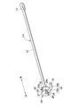
連結パイプ12の内孔13に挿入されたトーションバー14は、断面が円形の1本の鋼棒の両端部を屈曲させることによって形成されたものである。図3に示すように、トーションバー14は、左右方向に延在する軸部15と、軸部15の右端から軸部15に直交するように延出する第1延長部16a、及び第1延長部16aの先端から軸部15に平行に左方に延出する第2延長部16bを有する延長部16と、軸線回りの回転を規制し易いように、鋼棒の左端側の端部を折り返すことにより形成された折り返し部17とを有する。
図2に示すように、延長部16は、連結パイプ12の内孔13の外側に位置する。第2延長部16bは、軸部15よりも前方に位置し、右側のサイドフレーム8に設けられた係合孔18に係合している。第2延長部16bの上面には、第2延長部16bが係合孔18から右方に抜け出すことを防止するため、サイドフレーム8の係合孔18を画成している部分に係合する係合溝19が設けられている。トーションバー14の右端側は、延長部16が右側のサイドフレーム8に係合しているため、右側のサイドフレーム8に対して軸線回りに回転することが規制される。
連結パイプ12の本体部12aの左端側には、内孔13を狭めるように前後から本体部12aを凹ませて形成されたパイプつぶし部20が設けられている。トーションバー14の折り返し部17がパイプつぶし部20に内孔13内で挟持されることにより、トーションバー14の左端側は、連結パイプ12に対して軸線回りに回転することが規制される。
トーションバー14は、ねじれた状態で右側のサイドフレーム8及びパイプつぶし部20に係止されている。クッションフレーム5を上下動させると、右側のサイドフレーム8と、左右1対のリアリンク11,11及び連結パイプ12とのなす角が変化するため、右端側に於いて右側のサイドフレーム8に係合し、左端側に於いて連結パイプ12に係合したトーションバー14のねじれ角が変化する。クッションフレーム5を下降させるとトーションバー14のねじれ角が大きくなり、クッションフレーム5を上昇させるとトーションバー14のねじれ角が小さくなるように、トーションバー14は設置されているため、トーションバー14のねじれによって生じる付勢力は、クッションフレーム5を上昇させる向きに作用する。
駆動機構7は、左側のサイドフレーム8に固定された電動モータ21と、電動モータ21の回転によって回転するピニオン22と、左側のリアリンク11に固定されてピニオン22に噛み合うギヤ23とを有する。電動モータ21は、ピニオン22、ギヤ23及び左側のリアリンク11を介して、クッションフレーム5を上下方向に駆動する。このとき、右側のリアリンク11は連結パイプ12によって、左側のリアリンク11と連動し、左右1対のフロントリンク10,10は、左右1対のサイドフレーム8,8とフロントフレーム9とが互いに剛結されているため、左右1対のリアリンクと連動する。電動モータ21に代えて、手動でクッションフレーム5を駆動する構成としてもよい。
図1及び図2に示すように、トーションバー14の軸芯を、連結パイプ12の中心軸に一致させ、その状態を維持するために、連結パイプ12の右端側及びトーションバー14の軸部15の右端側との間には、位置保持部材24が取り付けられている。
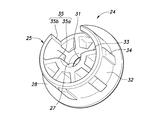
図3~図6に示すように、位置保持部材24は、トーションバー14の軸部15を保持するとともに連結パイプ12に取り付けられる本体部25と、トーションバー14の第1延長部16aに係合する係合部26とを有する一体成形品である。
本体部25は、左右方向に沿って貫通孔27が形成される円筒形の輪郭を有する。トーションバー14の軸部15が貫通孔27に挿通されて把持され、かつ、本体部25の円筒形の外周面が連結パイプ12の内孔13の内周面に当接することにより、トーションバー14の軸部15の軸芯の位置が維持される。軸部15の軸芯の位置が連結パイプ12に対してずれると、トーションバー14の付勢力が設計値からずれるが、位置保持部材24によってこのずれを防止できる。本体部25の右端には側周面から半径方向に延出する鍔部28が設けられて、鍔部28の左面が連結パイプ12の右端に当接することにより、位置保持部材24の連結パイプ12に対する左右方向位置が決まる(図2参照)。
図5に示すように、係合部26は、本体部25の右側の端面に設けられた、互いに対向する係合爪29及び係合凸部30を有する。係合爪29の遊端側は、第1延長部16aをオーバーハングするように(図3参照)、係合凸部30側に向かって屈曲しており、本体部25の右側の端面と係合爪29の遊端側との互いの対向面間の距離は、トーションバー14の第1延長部16aの直径に略等しい。係合爪29に於ける、第1延長部16aに面する側とは反対側の面には、強度補強のためのリブ29aが、両側縁に沿って設けられている。係合凸部30の頂部は、係合爪29の遊端よりも本体部25から突出しておらず、係合凸部30の頂部と係合爪29の遊端との距離は、通常は第1延長部16aの直径よりも小さいが、係合爪29が弾性変形することにより、第1延長部16aは、係合凸部30の頂部と係合爪29の遊端との間を通過できる。組み付け後、係合爪29が係合凸部30よりも上部に配置され、及び/又は、係合部26がサイドフレーム8よりも左右方向の外側に位置するように構成されることにより、係合状態を確認し易くなる。
係合凸部30は、半径方向から見て三角形を呈し、係合爪29に近づくにつれ本体部25から離間するガイド面30aと、ガイド面30aよりも係合爪29に近接する側に設けられて、係合爪29に近づくにつれ本体部25に近接する係止面30bとを有する。ガイド面30aは、位置保持部材24をトーションバー14に組み付ける際に第1延長部16aをガイドし、係止面30bは、両者を組み付けた状態において、係合爪29及び本体部25の右側の端面と協働して、第1延長部16aを把持する。本体部25の右側の端面に対する係止面30bの角度は、本体部25の右側の端面に対するガイド面30aの角度よりも急であるため、位置保持部材24及び第1延長部16a間の係合を解除するために位置保持部材24を逆回転させるときは、両者を係合させるために位置保持部材24を回転させるときよりも大きな力が必要である。なお、係合部26は、係合爪29及び係合凸部30に代えて、本体部25に設けた凹部(図示せず)によって構成してもよく、係合爪29と凹部との組み合わせによって構成してもよい。
図6に示すように、位置保持部材24の円筒形状の本体部25は、肉抜きされて2層構造となっており、貫通孔27を画成する内周壁31と、連結パイプ12の内孔13を画成する内周面に摺接して連結パイプ12に回転可能に支持される外周壁32と、半径方向に延在して内周壁31及び外周壁32間を連結する複数の補強壁33とを有する。位置保持部材24が連結パイプ12に対して軸線回りに回転するときの摩擦抵抗を減らすため、外周壁32の外周面には軸線方向に沿って複数のリブ34が設けられ、リブ34が連結パイプ12の内周面に摺接する。複数のリブ34は、トーションバー14からの横力を受ける側の所定の範囲に渡って、周方向に略等間隔に配置される。複数の補強壁33は、周方向に略等間隔に配置され、リブ34が設けられた側に位置する補強壁33は、半径方向においてリブ34と整合し、そのため、トーションバー14からの横力に対する補強が効率的となる。
位置保持部材24の内周壁31及び外周壁32は、それぞれ、左側の端面に、半径方向に延在するように凹設された内側受容溝35a及び外側受容溝35bを有する。内側受容溝35a及び外側受容溝35bは、リブ34とは周方向の反対側の、互いに半径方向に整合した位置に設けられる。内側受容溝35a及び外側受容溝35bの周方向の幅は、トーションバー14の直径に略等しい。位置保持部材24をトーションバー14に組み付ける際に、内側受容溝35aと外側受容溝35bとから構成される受容溝35がトーションバー14の延長部16を受容できるように、内側受容溝35a及び外側受容溝35bの左右方向の深さは設定される。受容溝35は、係合部26に対して周方向に約90°ずれた位置に設けられる。なお、受容溝35の位置の係合部26に対する角度は、両者が互いに周方向にずれている範囲において、変更可能である。また、受容溝35の近傍では強度が低くなるため、受容溝35は、位置保持部材24がトーションバーから受ける横力が最大となる側に対して周方向にずれた位置、例えば対角位置に設けられる。
組み付け方法及び作用効果について説明する。作業員は、トーションバー14の第2延長部16bの遊端を、位置保持部材24の左端側から貫通孔27に挿入し、位置保持部材24を軸部15の右端側まで移動させる。この時、位置保持部材24は、受容溝35があるため、軸部15に対して屈曲した延長部16を通過することができる。
次いで、作業員は、位置保持部材24をトーションバー14の軸部15に対して軸線回りに回転させる。この時、第1延長部16aは、係合凸部30のガイド面30aを摺動しながら係合爪29を弾性変形させた後、係合爪29及び係合凸部30間に配置される。係合爪29は、係合凸部30と協働して第1延長部16aを弾発的に保持する。
その後、作業員は、位置保持部材24が取り付けられたトーションバー14を連結パイプ12の内孔13に挿入し、トーションバー14の折り返し部17及び第2延長部16bを、それぞれ、パイプつぶし部20及び右側のサイドフレーム8に係合させる。
受容溝35があるため、トーションバー14が屈曲していても、その端部から位置保持部材24を挿入し、所定の位置まで移動させることができるため、組み付けが容易で、かつ、位置保持部材24を一体成形品にして部品点数を減らすことができる。
係合部26が第1延長部16aを係合すると、位置保持部材24のトーションバー14に対する軸線周りの回転及び左右方向への変位が記載され、位置保持部材24の位置及び姿勢が安定する。そのため、位置保持部材24をトーションバー14に組み付けた状態で出荷しても、位置保持部材24が外れたり、破損したりするリスクが小さい。
係合部26が第1延長部16aに係合することにより、位置保持部材24は、トーションバー14の軸部15の右端側とともに、連結パイプ12に対して回転する。そのため、位置保持部材24に於けるトーションバー14の横力が加わる位置が一定となり、位置保持部材24は、狭い角度範囲で横力に耐える強度を確保すれば十分である。そのため、位置保持部材24の小型化及び軽量化ができるとともに、横力の影響が小さい部分に受容溝35を設けることができる。
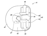
次に、図7~9を参照して、本発明の第2実施形態について説明する。なお、説明に当たって、第1実施形態と共通する構成については、説明を省略し、同じ符号を付す。第2実施形態では、位置保持部材41の形状及び組み付け方法が第1実施形態と異なる。
第2実施形態に係る位置保持部材41は、トーションバー14の軸部15を保持するとともに連結パイプ12に取り付けられる本体部42と、トーションバー14の第1延長部16aに係合する係合部43とを有する一体成形品である。
本体部42は、第1実施形態と同様に、左右方向に沿って貫通孔27を有する円筒形であり、内周壁31、外周壁32及び補強壁33を有する。なお、第1実施形態のリブ34に相当する構成は有さない。
図8に示すように、係合部43は、本体部42の右側の端面に設けられた、互いに対向する1対の係合爪44,44を有する。1対の係合爪44,44は、互いに鏡像対称形をなす。各々の係合爪44は、トーションバー14の延長部16に係合する係合片45と、係合片45において第1延長部16aに面する側とは反対側の面の両側縁に沿って設けられた強度補強のためのリブ46とを有する。本体部42の右端の側周面から半径方向に延出する鍔部47は、リブ46を設けるべき位置まで延出してリブ46を支持している。
係合片45の右方への突出長は、第1延長部16aの半径より長く、好ましくは、第1延長部16aの直径以上である。係合片45の第1延長部16aに面する側には、第1延長部16aの半径よりも本体部25から突出した部分に於いて、第1延長部16aの延在方向に沿って延在する突条48が設けられている。1対の係合片45,45間の距離は、第1延長部16aの直径に略等しい。また、1対の突条48,48間の距離は第1延長部16aの直径より狭く、各々の突条48の先端が第1延長部16aに圧接する。このため、1対の係合爪44,44は、第1延長部16aを弾発的に保持する。
組み付け方法及び作用効果について説明する。作業員は、トーションバー14の第2延長部16bの遊端を、位置保持部材41の左端側から貫通孔27に挿入し、位置保持部材41を軸部15の右端側まで移動させる。この時、位置保持部材41は、本来の位置保持部材41の左右方向位置よりも係合爪44の右方への突出長と同程度以上に左方に位置させる。位置保持部材41は、第1実施形態と同様に、受容溝35があるため、軸部15に対して屈曲した延長部16を通過することができる。
次いで、作業員は、位置保持部材41をトーションバー14の軸部15に対して軸線回りに回転させ、1対の係合爪44,44間の間隙を、トーションバー14の第1延長部16aに左右方向に於いて整合させた後、位置保持部材を右方に移動させる。この時、1対の突条48が互いに離間するように第1延長部16aに押し出されて、1対の係合爪44,44が弾性変形することにより、第1延長部16aが1対の係合爪44,44間を通過する。第1延長部16aの中心軸が、1対の突条48,48間を通過すると、1対の係合爪44,44の弾性変形が部分的に戻るため、1対の係合爪44,44は、第1延長部16aを弾発的に保持する。
その後、第1実施形態と同様に、作業員は、位置保持部材41が取り付けられたトーションバー14を連結パイプ12の内孔13に挿入し、トーションバー14の折り返し部17及び第2延長部16bを、それぞれ、パイプつぶし部20及び右側のサイドフレーム8に係合させる。
位置保持部材41が一体成形品であっても、受容溝35があるため、屈曲したトーションバー14に対して組みつけが容易である点は第1実施形態と同様である。
係合部43が第1延長部16aを係合すると、位置保持部材41は、トーションバー14に対して、1対の係合片45,45に係止されるため軸線回りに回転せず、1対の突条48,48及び本体部42の右面とに係止されるため左右方向への変位が規制される。そのため、位置保持部材24をトーションバー14に組み付けた状態で出荷しても、位置保持部材24が外れたり、破損したりするリスクが小さい。
第1実施形態と同様に、係合部43が第1延長部16aに係合することにより、位置保持部材41は、トーションバー14の軸部15の右端側とともに、連結パイプ12に対して回転する。そのため、位置保持部材41に於けるトーションバー14の横力が加わる位置が一定となり、位置保持部材41は、狭い角度範囲で横力に耐える強度を確保すれば十分である。そのため、位置保持部材41の小型化及び軽量化ができるとともに、横力を受けない部分に受容溝35を設けることができる。
以上で具体的実施形態の説明を終えるが、本発明は上記実施形態に限定されることなく幅広く変形実施することができる。上記実施形態に於いて、左右を逆にしてもよい。連結パイプを、クッションフレームの一部として、左右1対のリアリンクに枢支し、トーションバーの延長部をリアリンクに係合させてもよい。連結パイプ及びトーションバーを、ベース部材とリアリンクと枢支部と同軸に設け、連結パイプをベース部材及びリアリンクの一方に固定し、トーションバーの延長部をベース部材及びリアリンクの他方に係合させてもよい。連結パイプの形状については、位置保持部材を受容する部分が円形の内周面を有すればよく、他の部分が角管形状や棒状であってもよい。リアリンクに代えて、フロントリンクに対して、連結パイプ及びトーションバーを取り付けてもよい。本出願中で引用された従来技術の全内容は、それに言及したことをもって本願明細書の一部とする。
1:車両用シート
2:ベース部材
3:シートクッション
5:クッションフレーム
6:リンク機構
7:駆動機構
8:サイドフレーム(第2の部分)
11:リアリンク
12:連結パイプ(第1の部分)
13:内孔
14:トーションバー
15:軸部
16:延長部
24,41:位置保持部材
25,42:本体部
26:係合部
27:貫通孔
29,44:係合爪
30:係合凸部
31:内側壁
32:外周壁
33:補強壁
34:リブ
35:受容溝
2:ベース部材
3:シートクッション
5:クッションフレーム
6:リンク機構
7:駆動機構
8:サイドフレーム(第2の部分)
11:リアリンク
12:連結パイプ(第1の部分)
13:内孔
14:トーションバー
15:軸部
16:延長部
24,41:位置保持部材
25,42:本体部
26:係合部
27:貫通孔
29,44:係合爪
30:係合凸部
31:内側壁
32:外周壁
33:補強壁
34:リブ
35:受容溝
Claims (11)
- 車体に支持されたベース部材と、
シートクッションのフレームを構成するクッションフレームと、
前記ベース部材に対して前記クッションフレームを上下に変位可能に支持するリンク機構と、
前記リンク機構を介して前記クッションフレームを上下方向に駆動する駆動機構と、
前記クッションフレームを上方に向けて付勢するために、前記クッションフレームの左右側部間に延在し、かつ左右の第1端及び第2端にて、前記リンク機構の枢支部に於ける互いに相対回転する第1の部分及び第2の部分に結合されたトーションバーとを備える高さ調節可能な前記シートクッションを備えた車両用シートであって、
前記トーションバーが、左右方向に延在する軸部、及び、前記第2端側に於いて少なくとも部分的に前記軸部に交差する方向に延出して前記第2の部分に結合された延長部を有し、
前記第1の部分は、前記トーションバーの前記第1端を回転不能に支持し、前記トーションバーの前記軸部の前記第2端側を、前記トーションバーの軸芯の変位を抑制するための位置保持部材を介して支持し、
前記位置保持部材が、前記第1の部分に対して回転可能に支持され、前記軸部を挿通させる貫通孔を含む本体部と、前記延長部に一体回転するように係合する係合部とを有することを特徴とする車両用シート。 - 前記クッションフレーム及び前記リンク機構の何れか一方が、他方に対して回転可能な連結パイプを有し、
前記連結パイプが前記第1の部分を構成し、
前記位置保持部材の前記本体部が、円筒形の輪郭を有し、前記連結パイプの内孔に回転可能に受容されていることを特徴とする請求項1に記載の車両用シート。 - 前記位置保持部材の前記係合部は、前記本体部から突出する係合凸部と、前記本体部から突出して前記係合凸部と協働して前記延長部を弾発的に保持する係合爪とを有することを特徴とする請求項1に記載の車両用シート。
- 前記係合爪は、前記延長部をオーバーハングするように係止し、前記係合凸部よりも上方に配置されたことを特徴とすることを特徴とする請求項3に記載の車両用シート。
- 前記位置保持部材の前記係合部は、前記本体部から突出して前記延長部を弾発的に保持する1対の係合爪を有することを特徴とする請求項1に記載の車両用シート。
- 前記係合部は、前記第2の部分よりも左右方向の外側に位置することを特徴とする請求項1に記載の車両用シート。
- 前記位置保持部材が、左右方向の内側端面に、前記延長部を受容可能な、半径方向に延在するように凹設された受容溝を有し、かつ、一体成形品からなることを特徴とする請求項1に記載の車両用シート。
- 前記受容溝が、前記位置保持部材が前記トーションバーから受ける横力が最大となる側に対して周方向にずれた位置に設けられていることを特徴とする請求項7に記載の車両用シート。
- 前記位置保持部材が前記トーションバーから受ける横力が最大となる側が優先的に補強されていることを特徴とする請求項8に記載の車両用シート。
- 前記位置保持部材の前記本体部の外周面に軸線方向沿って延在する複数のリブが設けられていることを特徴とする請求項1に記載の車両用シート。
- 前記本体部の側周壁は、前記貫通孔を画成する内周壁と、前記第1の部分に回転可能に支持される外周壁と、半径方向に延在して前記内周壁及び前記外周壁間を連結する複数の補強壁とを有し、
少なくとも一部の前記補強壁は、前記リブと半径方向に整合する位置に設けられたことを特徴とする請求項10に記載の車両用シート。
Priority Applications (3)
| Application Number | Priority Date | Filing Date | Title |
|---|---|---|---|
| US16/498,037 US10953770B2 (en) | 2017-04-03 | 2018-03-23 | Vehicle seat |
| US17/203,970 US11364820B2 (en) | 2017-04-03 | 2021-03-17 | Vehicle seat |
| US17/832,078 US11654798B2 (en) | 2017-04-03 | 2022-06-03 | Vehicle seat |
Applications Claiming Priority (2)
| Application Number | Priority Date | Filing Date | Title |
|---|---|---|---|
| JP2017-073464 | 2017-04-03 | ||
| JP2017073464A JP6533247B2 (ja) | 2017-04-03 | 2017-04-03 | 車両用シート |
Related Child Applications (2)
| Application Number | Title | Priority Date | Filing Date |
|---|---|---|---|
| US16/498,037 A-371-Of-International US10953770B2 (en) | 2017-04-03 | 2018-03-23 | Vehicle seat |
| US17/203,970 Continuation US11364820B2 (en) | 2017-04-03 | 2021-03-17 | Vehicle seat |
Publications (1)
| Publication Number | Publication Date |
|---|---|
| WO2018186206A1 true WO2018186206A1 (ja) | 2018-10-11 |
Family
ID=63712446
Family Applications (1)
| Application Number | Title | Priority Date | Filing Date |
|---|---|---|---|
| PCT/JP2018/011654 Ceased WO2018186206A1 (ja) | 2017-04-03 | 2018-03-23 | 車両用シート |
Country Status (3)
| Country | Link |
|---|---|
| US (3) | US10953770B2 (ja) |
| JP (1) | JP6533247B2 (ja) |
| WO (1) | WO2018186206A1 (ja) |
Families Citing this family (3)
| Publication number | Priority date | Publication date | Assignee | Title |
|---|---|---|---|---|
| JP6533247B2 (ja) * | 2017-04-03 | 2019-06-19 | テイ・エス テック株式会社 | 車両用シート |
| DE102021101546B4 (de) | 2021-01-25 | 2022-05-05 | Brose Fahrzeugteile SE & Co. Kommanditgesellschaft, Coburg | Fahrzeugsitz |
| CN116265284A (zh) * | 2021-12-16 | 2023-06-20 | 延锋国际座椅系统有限公司 | 一种新型倾角调节机构以及汽车零压座椅 |
Citations (5)
| Publication number | Priority date | Publication date | Assignee | Title |
|---|---|---|---|---|
| JP2007230253A (ja) * | 2006-02-27 | 2007-09-13 | Fuji Kiko Co Ltd | シートリフター |
| WO2012038080A1 (de) * | 2010-09-24 | 2012-03-29 | Brose Fahrzeugteile Gmbh & Co. Kommanditgesellschaft, Coburg | Fahrzeugsitz mit in einem querrohr angeordneter drehstabfeder |
| US20120256465A1 (en) * | 2011-04-11 | 2012-10-11 | Thiel & Hoche Gmbh & Co. Kg | Motor vehicle seat crossmember |
| JP2015003577A (ja) * | 2013-06-20 | 2015-01-08 | トヨタ紡織株式会社 | 乗物用シート |
| WO2017022675A1 (ja) * | 2015-07-31 | 2017-02-09 | テイ・エス テック株式会社 | 車両用シート |
Family Cites Families (19)
| Publication number | Priority date | Publication date | Assignee | Title |
|---|---|---|---|---|
| GB2224198A (en) * | 1988-10-26 | 1990-05-02 | Ford Motor Co | Seat positioning mechanism |
| FR2748431B1 (fr) * | 1996-05-10 | 1998-07-24 | Faure Bertrand Equipements Sa | Mecanisme de reglage en position angulaire d'un bras articule sur un support |
| DE59912756D1 (de) * | 1998-08-12 | 2005-12-15 | Hammerstein Gmbh C Rob | Sitzträgergestell eines Fahrzeugsitzes mit einem linken und einem rechten vorderen Stellarm |
| US6517157B1 (en) * | 2001-03-16 | 2003-02-11 | Johnson Controls Technology Company | Apparatus for adjusting a seat belt |
| US6957796B2 (en) * | 2003-01-15 | 2005-10-25 | Lear Corporation | Hydro-formed seat adjuster system |
| EP1912822A2 (en) * | 2005-08-01 | 2008-04-23 | Johnson Controls Technology Company | Vehicle seat lift structure |
| JP4735187B2 (ja) * | 2005-10-24 | 2011-07-27 | アイシン精機株式会社 | 車両用シート調整装置 |
| KR101376465B1 (ko) * | 2006-03-27 | 2014-03-19 | 존슨 컨트롤스 테크놀러지 컴퍼니 | 시트 조정기용 전동 장치 |
| JP4900916B2 (ja) * | 2006-07-07 | 2012-03-21 | 株式会社タチエス | 車両用シートのハイト機構 |
| FR2942431B1 (fr) * | 2009-02-20 | 2011-03-11 | Faurecia Sieges Automobile | Siege de vehicule, procede de fabrication d'un tel siege de vehicule et machine pour la mise en oeuvre du procede de fabrication. |
| JP5218506B2 (ja) * | 2010-09-17 | 2013-06-26 | アイシン精機株式会社 | シートリフター装置 |
| US20130187418A1 (en) * | 2010-09-30 | 2013-07-25 | Ts Tech Co., Ltd. | Vehicle Seat |
| KR101219848B1 (ko) * | 2010-12-01 | 2013-01-08 | 현대자동차주식회사 | 차량용 시트 프레임의 회전방지장치 |
| CN103702864B (zh) * | 2011-07-26 | 2017-04-19 | C.劳勃.汉默斯坦两合有限公司 | 具有两个侧部件及横管的机动车座椅的座椅框架 |
| WO2013137354A1 (ja) * | 2012-03-14 | 2013-09-19 | テイ・エス テック株式会社 | フレーム付き機器 |
| CN104395144B (zh) * | 2012-03-27 | 2016-11-09 | 提爱思科技股份有限公司 | 车用座椅 |
| EP2805850B1 (en) * | 2013-05-22 | 2016-02-17 | Tachi-S Co., Ltd. | Vehicle seat |
| CN106794783B (zh) * | 2014-10-16 | 2019-01-22 | 株式会社三角工具加工 | 座椅支承机构、座椅结构以及悬架座位 |
| JP6533247B2 (ja) * | 2017-04-03 | 2019-06-19 | テイ・エス テック株式会社 | 車両用シート |
-
2017
- 2017-04-03 JP JP2017073464A patent/JP6533247B2/ja active Active
-
2018
- 2018-03-23 WO PCT/JP2018/011654 patent/WO2018186206A1/ja not_active Ceased
- 2018-03-23 US US16/498,037 patent/US10953770B2/en active Active
-
2021
- 2021-03-17 US US17/203,970 patent/US11364820B2/en active Active
-
2022
- 2022-06-03 US US17/832,078 patent/US11654798B2/en active Active
Patent Citations (5)
| Publication number | Priority date | Publication date | Assignee | Title |
|---|---|---|---|---|
| JP2007230253A (ja) * | 2006-02-27 | 2007-09-13 | Fuji Kiko Co Ltd | シートリフター |
| WO2012038080A1 (de) * | 2010-09-24 | 2012-03-29 | Brose Fahrzeugteile Gmbh & Co. Kommanditgesellschaft, Coburg | Fahrzeugsitz mit in einem querrohr angeordneter drehstabfeder |
| US20120256465A1 (en) * | 2011-04-11 | 2012-10-11 | Thiel & Hoche Gmbh & Co. Kg | Motor vehicle seat crossmember |
| JP2015003577A (ja) * | 2013-06-20 | 2015-01-08 | トヨタ紡織株式会社 | 乗物用シート |
| WO2017022675A1 (ja) * | 2015-07-31 | 2017-02-09 | テイ・エス テック株式会社 | 車両用シート |
Also Published As
| Publication number | Publication date |
|---|---|
| US11364820B2 (en) | 2022-06-21 |
| US20220289080A1 (en) | 2022-09-15 |
| US10953770B2 (en) | 2021-03-23 |
| US11654798B2 (en) | 2023-05-23 |
| US20200023754A1 (en) | 2020-01-23 |
| JP6533247B2 (ja) | 2019-06-19 |
| JP2018176758A (ja) | 2018-11-15 |
| US20210197694A1 (en) | 2021-07-01 |
Similar Documents
| Publication | Publication Date | Title |
|---|---|---|
| JP5176555B2 (ja) | フレーム構造 | |
| US11654798B2 (en) | Vehicle seat | |
| CN103003100B (zh) | 乘坐物用座椅 | |
| JP2011136648A (ja) | 車両用シート | |
| JP2024174198A (ja) | 乗り物用シート | |
| JP2014097724A (ja) | 車両用シートスライド装置 | |
| WO2018029898A1 (ja) | 車両用シート | |
| WO2014041643A1 (ja) | 車両用シート及びその製造方法 | |
| US10821867B2 (en) | Headrest support device | |
| JP6718129B2 (ja) | 車両用シート | |
| JP5206376B2 (ja) | 車体骨格材構造 | |
| JP6963197B2 (ja) | 車両用シート | |
| JP2009131340A (ja) | リフタ付きシート | |
| JP2022145870A5 (ja) | ||
| JP2008087558A (ja) | 車両用シート装置 | |
| WO2016199299A1 (ja) | ヘッドレスト | |
| JP7328570B2 (ja) | 車両用シート | |
| JP4673228B2 (ja) | リフタ付きベルトインシート | |
| JP6245061B2 (ja) | 乗物用シート | |
| WO2018029897A1 (ja) | 車両用シート | |
| JP5955046B2 (ja) | 車両用シート | |
| JP2017154558A (ja) | ステアリング装置 | |
| JP6048594B2 (ja) | テレスコピックステアリング装置用アウタコラム | |
| JP5629514B2 (ja) | 乗物用シート | |
| JP2008018820A (ja) | 衝撃吸収式ステアリングコラム装置 |
Legal Events
| Date | Code | Title | Description |
|---|---|---|---|
| 121 | Ep: the epo has been informed by wipo that ep was designated in this application |
Ref document number: 18780794 Country of ref document: EP Kind code of ref document: A1 |
|
| NENP | Non-entry into the national phase |
Ref country code: DE |
|
| 122 | Ep: pct application non-entry in european phase |
Ref document number: 18780794 Country of ref document: EP Kind code of ref document: A1 |