WO2018173455A1 - 運転支援装置 - Google Patents
運転支援装置 Download PDFInfo
- Publication number
- WO2018173455A1 WO2018173455A1 PCT/JP2018/001889 JP2018001889W WO2018173455A1 WO 2018173455 A1 WO2018173455 A1 WO 2018173455A1 JP 2018001889 W JP2018001889 W JP 2018001889W WO 2018173455 A1 WO2018173455 A1 WO 2018173455A1
- Authority
- WO
- WIPO (PCT)
- Prior art keywords
- notification
- driver
- level
- vehicle
- index value
- Prior art date
- Legal status (The legal status is an assumption and is not a legal conclusion. Google has not performed a legal analysis and makes no representation as to the accuracy of the status listed.)
- Ceased
Links
Images


Classifications
-
- B—PERFORMING OPERATIONS; TRANSPORTING
- B60—VEHICLES IN GENERAL
- B60W—CONJOINT CONTROL OF VEHICLE SUB-UNITS OF DIFFERENT TYPE OR DIFFERENT FUNCTION; CONTROL SYSTEMS SPECIALLY ADAPTED FOR HYBRID VEHICLES; ROAD VEHICLE DRIVE CONTROL SYSTEMS FOR PURPOSES NOT RELATED TO THE CONTROL OF A PARTICULAR SUB-UNIT
- B60W50/00—Details of control systems for road vehicle drive control not related to the control of a particular sub-unit, e.g. process diagnostic or vehicle driver interfaces
- B60W50/08—Interaction between the driver and the control system
- B60W50/14—Means for informing the driver, warning the driver or prompting a driver intervention
-
- B—PERFORMING OPERATIONS; TRANSPORTING
- B60—VEHICLES IN GENERAL
- B60K—ARRANGEMENT OR MOUNTING OF PROPULSION UNITS OR OF TRANSMISSIONS IN VEHICLES; ARRANGEMENT OR MOUNTING OF PLURAL DIVERSE PRIME-MOVERS IN VEHICLES; AUXILIARY DRIVES FOR VEHICLES; INSTRUMENTATION OR DASHBOARDS FOR VEHICLES; ARRANGEMENTS IN CONNECTION WITH COOLING, AIR INTAKE, GAS EXHAUST OR FUEL SUPPLY OF PROPULSION UNITS IN VEHICLES
- B60K35/00—Instruments specially adapted for vehicles; Arrangement of instruments in or on vehicles
- B60K35/20—Output arrangements, i.e. from vehicle to user, associated with vehicle functions or specially adapted therefor
- B60K35/28—Output arrangements, i.e. from vehicle to user, associated with vehicle functions or specially adapted therefor characterised by the type of the output information, e.g. video entertainment or vehicle dynamics information; characterised by the purpose of the output information, e.g. for attracting the attention of the driver
-
- B—PERFORMING OPERATIONS; TRANSPORTING
- B60—VEHICLES IN GENERAL
- B60K—ARRANGEMENT OR MOUNTING OF PROPULSION UNITS OR OF TRANSMISSIONS IN VEHICLES; ARRANGEMENT OR MOUNTING OF PLURAL DIVERSE PRIME-MOVERS IN VEHICLES; AUXILIARY DRIVES FOR VEHICLES; INSTRUMENTATION OR DASHBOARDS FOR VEHICLES; ARRANGEMENTS IN CONNECTION WITH COOLING, AIR INTAKE, GAS EXHAUST OR FUEL SUPPLY OF PROPULSION UNITS IN VEHICLES
- B60K35/00—Instruments specially adapted for vehicles; Arrangement of instruments in or on vehicles
- B60K35/20—Output arrangements, i.e. from vehicle to user, associated with vehicle functions or specially adapted therefor
- B60K35/29—Instruments characterised by the way in which information is handled, e.g. showing information on plural displays or prioritising information according to driving conditions
-
- B—PERFORMING OPERATIONS; TRANSPORTING
- B60—VEHICLES IN GENERAL
- B60W—CONJOINT CONTROL OF VEHICLE SUB-UNITS OF DIFFERENT TYPE OR DIFFERENT FUNCTION; CONTROL SYSTEMS SPECIALLY ADAPTED FOR HYBRID VEHICLES; ROAD VEHICLE DRIVE CONTROL SYSTEMS FOR PURPOSES NOT RELATED TO THE CONTROL OF A PARTICULAR SUB-UNIT
- B60W30/00—Purposes of road vehicle drive control systems not related to the control of a particular sub-unit, e.g. of systems using conjoint control of vehicle sub-units
- B60W30/08—Active safety systems predicting or avoiding probable or impending collision or attempting to minimise its consequences
- B60W30/095—Predicting travel path or likelihood of collision
- B60W30/0956—Predicting travel path or likelihood of collision the prediction being responsive to traffic or environmental parameters
-
- B—PERFORMING OPERATIONS; TRANSPORTING
- B60—VEHICLES IN GENERAL
- B60K—ARRANGEMENT OR MOUNTING OF PROPULSION UNITS OR OF TRANSMISSIONS IN VEHICLES; ARRANGEMENT OR MOUNTING OF PLURAL DIVERSE PRIME-MOVERS IN VEHICLES; AUXILIARY DRIVES FOR VEHICLES; INSTRUMENTATION OR DASHBOARDS FOR VEHICLES; ARRANGEMENTS IN CONNECTION WITH COOLING, AIR INTAKE, GAS EXHAUST OR FUEL SUPPLY OF PROPULSION UNITS IN VEHICLES
- B60K2360/00—Indexing scheme associated with groups B60K35/00 or B60K37/00 relating to details of instruments or dashboards
- B60K2360/16—Type of output information
- B60K2360/178—Warnings
-
- B—PERFORMING OPERATIONS; TRANSPORTING
- B60—VEHICLES IN GENERAL
- B60K—ARRANGEMENT OR MOUNTING OF PROPULSION UNITS OR OF TRANSMISSIONS IN VEHICLES; ARRANGEMENT OR MOUNTING OF PLURAL DIVERSE PRIME-MOVERS IN VEHICLES; AUXILIARY DRIVES FOR VEHICLES; INSTRUMENTATION OR DASHBOARDS FOR VEHICLES; ARRANGEMENTS IN CONNECTION WITH COOLING, AIR INTAKE, GAS EXHAUST OR FUEL SUPPLY OF PROPULSION UNITS IN VEHICLES
- B60K2360/00—Indexing scheme associated with groups B60K35/00 or B60K37/00 relating to details of instruments or dashboards
- B60K2360/16—Type of output information
- B60K2360/179—Distances to obstacles or vehicles
-
- B—PERFORMING OPERATIONS; TRANSPORTING
- B60—VEHICLES IN GENERAL
- B60K—ARRANGEMENT OR MOUNTING OF PROPULSION UNITS OR OF TRANSMISSIONS IN VEHICLES; ARRANGEMENT OR MOUNTING OF PLURAL DIVERSE PRIME-MOVERS IN VEHICLES; AUXILIARY DRIVES FOR VEHICLES; INSTRUMENTATION OR DASHBOARDS FOR VEHICLES; ARRANGEMENTS IN CONNECTION WITH COOLING, AIR INTAKE, GAS EXHAUST OR FUEL SUPPLY OF PROPULSION UNITS IN VEHICLES
- B60K2360/00—Indexing scheme associated with groups B60K35/00 or B60K37/00 relating to details of instruments or dashboards
- B60K2360/18—Information management
- B60K2360/186—Displaying information according to relevancy
-
- B—PERFORMING OPERATIONS; TRANSPORTING
- B60—VEHICLES IN GENERAL
- B60K—ARRANGEMENT OR MOUNTING OF PROPULSION UNITS OR OF TRANSMISSIONS IN VEHICLES; ARRANGEMENT OR MOUNTING OF PLURAL DIVERSE PRIME-MOVERS IN VEHICLES; AUXILIARY DRIVES FOR VEHICLES; INSTRUMENTATION OR DASHBOARDS FOR VEHICLES; ARRANGEMENTS IN CONNECTION WITH COOLING, AIR INTAKE, GAS EXHAUST OR FUEL SUPPLY OF PROPULSION UNITS IN VEHICLES
- B60K35/00—Instruments specially adapted for vehicles; Arrangement of instruments in or on vehicles
- B60K35/20—Output arrangements, i.e. from vehicle to user, associated with vehicle functions or specially adapted therefor
- B60K35/21—Output arrangements, i.e. from vehicle to user, associated with vehicle functions or specially adapted therefor using visual output, e.g. blinking lights or matrix displays
-
- B—PERFORMING OPERATIONS; TRANSPORTING
- B60—VEHICLES IN GENERAL
- B60K—ARRANGEMENT OR MOUNTING OF PROPULSION UNITS OR OF TRANSMISSIONS IN VEHICLES; ARRANGEMENT OR MOUNTING OF PLURAL DIVERSE PRIME-MOVERS IN VEHICLES; AUXILIARY DRIVES FOR VEHICLES; INSTRUMENTATION OR DASHBOARDS FOR VEHICLES; ARRANGEMENTS IN CONNECTION WITH COOLING, AIR INTAKE, GAS EXHAUST OR FUEL SUPPLY OF PROPULSION UNITS IN VEHICLES
- B60K35/00—Instruments specially adapted for vehicles; Arrangement of instruments in or on vehicles
- B60K35/20—Output arrangements, i.e. from vehicle to user, associated with vehicle functions or specially adapted therefor
- B60K35/25—Output arrangements, i.e. from vehicle to user, associated with vehicle functions or specially adapted therefor using haptic output
-
- B—PERFORMING OPERATIONS; TRANSPORTING
- B60—VEHICLES IN GENERAL
- B60K—ARRANGEMENT OR MOUNTING OF PROPULSION UNITS OR OF TRANSMISSIONS IN VEHICLES; ARRANGEMENT OR MOUNTING OF PLURAL DIVERSE PRIME-MOVERS IN VEHICLES; AUXILIARY DRIVES FOR VEHICLES; INSTRUMENTATION OR DASHBOARDS FOR VEHICLES; ARRANGEMENTS IN CONNECTION WITH COOLING, AIR INTAKE, GAS EXHAUST OR FUEL SUPPLY OF PROPULSION UNITS IN VEHICLES
- B60K35/00—Instruments specially adapted for vehicles; Arrangement of instruments in or on vehicles
- B60K35/20—Output arrangements, i.e. from vehicle to user, associated with vehicle functions or specially adapted therefor
- B60K35/26—Output arrangements, i.e. from vehicle to user, associated with vehicle functions or specially adapted therefor using acoustic output
-
- B—PERFORMING OPERATIONS; TRANSPORTING
- B60—VEHICLES IN GENERAL
- B60K—ARRANGEMENT OR MOUNTING OF PROPULSION UNITS OR OF TRANSMISSIONS IN VEHICLES; ARRANGEMENT OR MOUNTING OF PLURAL DIVERSE PRIME-MOVERS IN VEHICLES; AUXILIARY DRIVES FOR VEHICLES; INSTRUMENTATION OR DASHBOARDS FOR VEHICLES; ARRANGEMENTS IN CONNECTION WITH COOLING, AIR INTAKE, GAS EXHAUST OR FUEL SUPPLY OF PROPULSION UNITS IN VEHICLES
- B60K35/00—Instruments specially adapted for vehicles; Arrangement of instruments in or on vehicles
- B60K35/60—Instruments characterised by their location or relative disposition in or on vehicles
-
- B—PERFORMING OPERATIONS; TRANSPORTING
- B60—VEHICLES IN GENERAL
- B60W—CONJOINT CONTROL OF VEHICLE SUB-UNITS OF DIFFERENT TYPE OR DIFFERENT FUNCTION; CONTROL SYSTEMS SPECIALLY ADAPTED FOR HYBRID VEHICLES; ROAD VEHICLE DRIVE CONTROL SYSTEMS FOR PURPOSES NOT RELATED TO THE CONTROL OF A PARTICULAR SUB-UNIT
- B60W50/00—Details of control systems for road vehicle drive control not related to the control of a particular sub-unit, e.g. process diagnostic or vehicle driver interfaces
- B60W50/08—Interaction between the driver and the control system
- B60W50/14—Means for informing the driver, warning the driver or prompting a driver intervention
- B60W2050/143—Alarm means
-
- B—PERFORMING OPERATIONS; TRANSPORTING
- B60—VEHICLES IN GENERAL
- B60W—CONJOINT CONTROL OF VEHICLE SUB-UNITS OF DIFFERENT TYPE OR DIFFERENT FUNCTION; CONTROL SYSTEMS SPECIALLY ADAPTED FOR HYBRID VEHICLES; ROAD VEHICLE DRIVE CONTROL SYSTEMS FOR PURPOSES NOT RELATED TO THE CONTROL OF A PARTICULAR SUB-UNIT
- B60W50/00—Details of control systems for road vehicle drive control not related to the control of a particular sub-unit, e.g. process diagnostic or vehicle driver interfaces
- B60W50/08—Interaction between the driver and the control system
- B60W50/14—Means for informing the driver, warning the driver or prompting a driver intervention
- B60W2050/146—Display means
-
- B—PERFORMING OPERATIONS; TRANSPORTING
- B60—VEHICLES IN GENERAL
- B60W—CONJOINT CONTROL OF VEHICLE SUB-UNITS OF DIFFERENT TYPE OR DIFFERENT FUNCTION; CONTROL SYSTEMS SPECIALLY ADAPTED FOR HYBRID VEHICLES; ROAD VEHICLE DRIVE CONTROL SYSTEMS FOR PURPOSES NOT RELATED TO THE CONTROL OF A PARTICULAR SUB-UNIT
- B60W2554/00—Input parameters relating to objects
- B60W2554/80—Spatial relation or speed relative to objects
- B60W2554/801—Lateral distance
-
- B—PERFORMING OPERATIONS; TRANSPORTING
- B60—VEHICLES IN GENERAL
- B60W—CONJOINT CONTROL OF VEHICLE SUB-UNITS OF DIFFERENT TYPE OR DIFFERENT FUNCTION; CONTROL SYSTEMS SPECIALLY ADAPTED FOR HYBRID VEHICLES; ROAD VEHICLE DRIVE CONTROL SYSTEMS FOR PURPOSES NOT RELATED TO THE CONTROL OF A PARTICULAR SUB-UNIT
- B60W2554/00—Input parameters relating to objects
- B60W2554/80—Spatial relation or speed relative to objects
- B60W2554/804—Relative longitudinal speed
Definitions
- the present disclosure relates to a driving support device that warns a driver of a possibility of a collision with a preceding vehicle.
- a driving support device that warns a driver of the possibility of a collision with a preceding vehicle by outputting an alarm sound according to the distance between the preceding vehicle and the vehicle.
- a safe inter-vehicle distance is calculated according to the vehicle speed of the host vehicle, and a risk degree that is a value obtained by dividing the calculated safe inter-vehicle distance by an inter-vehicle distance from an actual preceding vehicle is sequentially calculated.
- a driving support device that outputs an alarm sound in a mode according to the degree of danger is disclosed. Specifically, when the degree of danger is 1 or more and less than 1.5, the first stage alarm sound is output, and when the degree of danger is 1.5 or more and less than 2.0, the second stage alarm sound is output. Is output. When the degree of danger is 2.0 or more, a third-stage alarm sound is output.
- the alarm sound continues to be output in the same notification mode until the degree of danger exceeds or falls below a predetermined threshold (hereinafter, alarm threshold) that defines the output mode of the alarm sound. Therefore, even when the preceding vehicle suddenly brakes, the alarm sound in a relatively weak mode continues to be output until the inter-vehicle distance is sufficiently reduced so that the degree of danger exceeds the alarm threshold.
- alarm threshold a predetermined threshold that defines the output mode of the alarm sound. Therefore, even when the preceding vehicle suddenly brakes, the alarm sound in a relatively weak mode continues to be output until the inter-vehicle distance is sufficiently reduced so that the degree of danger exceeds the alarm threshold.
- alarm threshold a predetermined threshold
- This disclosure is intended to provide a driving support device that can notify a driver of the danger of a collision with a preceding vehicle in a more appropriate notification mode.
- the driving support device that performs a notification process that is a process of notifying the driver of the danger of a collision with the preceding vehicle in cooperation with a predetermined notification device is configured to calculate the inter-vehicle distance between the preceding vehicle and the host vehicle. It is a parameter indicating the degree of danger that the preceding vehicle and the host vehicle collide based on the inter-vehicle distance acquiring unit that is sequentially acquired, the traveling speed of the host vehicle, and the inter-vehicle distance that is acquired by the inter-vehicle distance acquiring unit.
- a first index value calculation unit that calculates a first risk index value, and a parameter that indicates a degree of danger that the preceding vehicle and the host vehicle collide with each other, and a second risk that is a parameter different from the first risk index value
- a second index value calculation unit that sequentially calculates an index value based on the relative speed of the host vehicle with respect to the preceding vehicle, and the first risk index value and the second index value calculation that are calculated by the first index value calculation unit Part is calculated
- a notification level determination unit that sequentially determines a notification level indicating the strength of appealing the driver to the danger of a collision with a preceding vehicle based on the second risk index value, and the notification level determination unit
- a notification processing unit that performs the notification processing in a notification mode according to the determined notification level.
- the second risk index value is a parameter determined according to the relative speed, when the preceding vehicle performs sudden braking, the second risk index value is also relative in response to the sudden braking of the preceding vehicle. It shifts to a value indicating that the degree of danger is high. And since the alerting level which determines the alerting
- the notification mode can change based on the sudden braking of the preceding vehicle, so that the driver notices the sudden braking of the preceding vehicle. Can also be reduced. That is, according to the said structure, a risk can be alert
- the drawing It is a block diagram which shows the schematic structure of the driving assistance system 100, It is the figure which showed an example of the mounting position of the peripheral vision device 2C, It is a figure which shows schematic structure of driving assistance ECU1, It is the figure which showed the relationship between safe inter-vehicle distance Ls and driving speed Vh, It is a figure for demonstrating the action
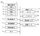
- the driving support system 100 includes a driving support ECU 1, a notification device 2, a front monitoring sensor 3, a narrow area communication unit 4, a vehicle state sensor 5, and a locator 6.
- the notification device 2 here is a device that notifies predetermined information to an occupant (hereinafter referred to as a driver) seated in a driver's seat using sound, light, vibration, or the like.
- the driving support system 100 of the present embodiment is assumed to include a speaker 2A, a display 2B, a peripheral vision device 2C, and a tactile device 2D as the notification device 2.
- ECU in the member name is an abbreviation for Electronic Control Unit, and means an electronic control device.
- Each of the various notification devices 2, the forward monitoring sensor 3, the narrow area communication unit 4, the vehicle state sensor 5, and the locator 6 is connected via a communication network (hereinafter referred to as LAN: Local Area Network) built in the vehicle.
- the driving support ECU 1 is communicably connected.
- the vehicle on which the driving support system 100 is mounted is also referred to as own vehicle Hv.
- the driving assistance ECU 1 sequentially determines the risk of a collision with the preceding vehicle Pv, and determines that the possibility of a collision with the preceding vehicle Pv is equal to or higher than a predetermined level, the driver assists the driver in cooperation with the notification device 2.
- This is an ECU that performs a process of notifying the danger of a collision with the preceding vehicle Pv (hereinafter, a notification process).
- the driving support ECU 1 corresponds to a driving support device.
- the driving support ECU 1 is configured as a computer. That is, the driving assistance ECU 1 includes a CPU 11 that executes various arithmetic processes, a flash memory 12 that is a nonvolatile memory, a RAM 13 that is a volatile memory, an I / O 14, and a bus line that connects these configurations. .
- the CPU 11 may be realized using, for example, a microprocessor.
- the I / O 14 is an interface for the driving support ECU 1 to input / output data with an external device (for example, the front monitoring sensor 3).
- the I / O 14 may be realized using an IC, a digital circuit element, an analog circuit element, or the like.
- the flash memory 12 stores a program for causing a normal computer to function as the driving assistance ECU 1 (hereinafter, driving assistance program).
- driving assistance program may be stored in a non-transitory tangible storage medium (non- transitory tangible storage medium) including the flash memory 12.
- Executing the driving support program by the CPU 11 corresponds to executing a method corresponding to the driving support program.
- the driving support ECU 1 provides various functions when the CPU 11 executes the driving support program. Various functions of the driving support ECU 1 will be described later.
- Speaker 2A outputs sound and alarm sound based on the signal input from driving support ECU1.
- the speaker 2A may be a parametric speaker that realizes a sharp directivity by using ultrasonic waves.
- the display 2B is a device that displays an image input from the driving support ECU 1.
- the display 2B is a display (so-called center display) provided at the uppermost portion of the instrument panel in the vehicle width direction center (hereinafter referred to as the center region).
- the display 2B is capable of full color display and can be realized using a liquid crystal display, an organic EL display, a plasma display, or the like.
- the display 2B may be a head-up display that projects a virtual image on a part of the windshield in front of the driver's seat.
- the display 2B may be a display (so-called meter display) arranged in a region located in front of the driver's seat on the instrument panel.
- the display 2B may be a display mounted at a position other than the position described above, or a display included in an information processing terminal brought into the vehicle interior by a driver.
- Peripheral vision device 2C is a light emitting device realized using LEDs or the like.
- the peripheral vision device 2C is disposed at a position that enters the peripheral visual field of the driver whose line of sight is directed in the front direction of the host vehicle Hv.
- the peripheral visual field here refers to a region that is out of the effective visual field and enters the field of view.
- the effective visual field may be assumed to be a range in which, for example, the vertical direction is within 30 degrees and the horizontal direction is within 20 degrees with reference to the direction in which the line of sight is directed.
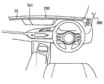
- the part that enters the peripheral vision of the driver whose line of sight is directed in the front direction of the host vehicle Hv in the passenger compartment is, for example, the upper surface portion (hereinafter, instrument panel upper surface portion) 200 of the instrument panel or the vehicle interior side of the front pillar.
- the surface portion 300 is, for example, the upper surface portion (hereinafter, instrument panel upper surface portion) 200 of the instrument panel or the vehicle interior side of the front pillar.
- the peripheral vision device 2C is realized by arranging a plurality of light emitting elements along the vehicle width direction on the instrument panel upper surface portion 200 as shown in FIG.
- the plurality of light emitting elements constituting the peripheral vision device 2 ⁇ / b> C may be disposed along a portion where the lower end portion of the windshield and the instrument panel upper surface portion 200 are connected to each other, or at the edge on the seat side in the instrument panel upper surface portion 200. It may be arranged along.
- the peripheral vision device 2 ⁇ / b> C causes some or all of the plurality of light emitting elements to emit light based on an instruction from the driving support ECU 1.
- the peripheral vision device 2C forms a partial attraction spot Spt by causing the light emitting element at a position corresponding to the instruction content from the driving support ECU 1 to emit light in a predetermined light emission mode.
- Elements constituting the light emission mode include color, luminance, blinking presence / absence, blinking interval, and the like. Since the attracting spot Spt itself provided by the peripheral vision device 2C is realized by causing a part of the plurality of light emitting elements to emit light locally, the position of the attracting spot Spt can be moved in the width direction. In addition, the peripheral vision device 2C can change the emission color and emission size of the attracting spot Spt.
- the tactile device 2D is a device that stimulates the tactile sensation of the driver by generating vibration or the like.
- a vibrator disposed on a portion that comes into contact with the driver's body, such as a steering wheel, an accelerator pedal, a brake pedal, a driver's seat, or a seat belt, can be employed.
- the haptic device 2D is a vibrator arranged on an accelerator pedal.
- the tactile device 2D generates a vibration in the instructed vibration mode based on an instruction from the driving support ECU 1.
- the vibration mode here includes the intensity of vibration, the generation interval of vibration, and the like.
- the tactile device 2D is not limited to vibration, and may be a device that applies a pressing force to a driver's hand or an illusion of traction force using a mechanism that performs asymmetric vibration, for example.
- the tactile sense here also includes warm sense. That is, the tactile device 2D may stimulate the driver's tactile sense using heat.
- the medium for transferring heat may be a steering wheel or the like, or air blown from an air conditioner.
- the front monitoring sensor 3 is a device that collects information about other vehicles in front of the host vehicle Hv and the traveling environment.
- a forward monitoring camera that images a predetermined range in front of the vehicle
- a millimeter wave radar that transmits an exploration wave to the predetermined range in front of the vehicle
- LIDAR Light Detection and Ranging / Laser Imaging Detection and Ranging
- Sonar etc.
- the driving support system 100 includes, as the forward monitoring sensor 3, a forward monitoring camera that is mounted so as to image the front of the vehicle, and a millimeter wave radar (hereinafter referred to as a forward radar) that uses the front of the vehicle as a detection area. Shall.
- the front monitoring camera as the front monitoring sensor 3 sequentially outputs captured images to the driving assistance ECU 1.
- the forward radar as the forward monitoring sensor 3 detects another vehicle (that is, the preceding vehicle Pv) traveling in front of the host vehicle Hv by transmitting and receiving an exploration wave, and when detecting the preceding vehicle Pv, The inter-vehicle distance and relative speed Vr between the preceding vehicle Pv and the host vehicle Hv are sequentially detected.
- Leading vehicles include motorbikes, motorcycles, and bicycles. Data indicating the inter-vehicle distance from the preceding vehicle Pv and the relative speed Vr are sequentially provided to the driving support ECU 1 as detection result data.
- the relative speed Vr may represent a relative speed of the preceding vehicle Pv with respect to the host vehicle Hv.
- the narrow area communication unit 4 is a communication module for performing direct (in other words, not via a wide area communication network) wireless communication with other vehicles existing around the vehicle Hv using radio waves in a predetermined frequency band. is there. That is, the narrow area communication part 4 is a communication module for implementing vehicle-to-vehicle communication.
- the frequency band used for vehicle-to-vehicle communication is, for example, the 760 MHz band.
- a 2.4 GHz band, a 5.9 GHz band, or the like can be used.
- Any communication standard for realizing vehicle-to-vehicle communication can be adopted.
- the standard of WAVE (Wireless Access in Vehicular Environment) disclosed in IEEE1609 or the like can be adopted.
- the narrow area communication unit 4 When receiving the vehicle information packet transmitted from the other vehicle, the narrow area communication unit 4 provides the data shown in the vehicle information packet to the driving support ECU 1.
- the vehicle information packet here is a communication packet indicating the vehicle information of the vehicle (that is, the transmission source vehicle) that has transmitted the vehicle information packet.
- the vehicle information includes the current position, traveling direction, traveling speed, acceleration, and the like of the transmission source vehicle.
- the vehicle information packet includes information such as the transmission time of the communication packet and transmission source information.
- the transmission source information is an identification number (so-called vehicle ID) assigned to the vehicle corresponding to the transmission source. That is, the narrow area communication unit 4 sequentially provides the driving support ECU 1 with vehicle information (hereinafter, other vehicle information) of the other vehicle indicated in the vehicle information packet transmitted from the other vehicle as needed.
- the driving support ECU 1 is configured to acquire the vehicle information of the other vehicle by communication not via the wide area communication network, but is not limited thereto.
- the driving assistance ECU 1 may be configured to acquire vehicle information of other vehicles via a wide area communication network.
- the vehicle state sensor 5 is a sensor that detects a state quantity related to traveling control of the host vehicle Hv.
- Examples of the vehicle state sensor 5 include a vehicle speed sensor, an acceleration sensor, a shift position sensor, a rudder angle sensor, an accelerator sensor, and a brake sensor.
- the vehicle speed sensor is a sensor that detects the traveling speed Vh of the host vehicle Hv
- the acceleration sensor is a sensor that detects acceleration acting in the vehicle longitudinal direction and acceleration acting in the vehicle width direction.
- the shift position sensor is a sensor that detects the position of the shift lever.
- the steering angle sensor is a sensor that detects the rotation angle (so-called steering angle) of the steering wheel, and functions as a sensor that detects the steering amount of the driver.
- the brake sensor is a sensor that detects the position of the brake pedal, in other words, the amount by which the brake pedal is depressed by the driver (hereinafter referred to as brake depression amount).
- the accelerator sensor is a sensor that detects the position of the accelerator pedal, in other words, the amount by which the accelerator pedal is depressed by the driver (hereinafter referred to as accelerator depression amount).
- Each sensor sequentially provides the driving support ECU 1 with data indicating the current value (that is, the detection result) of the physical state quantity to be detected.
- the type of sensor that the driving support system 100 should have as the vehicle state sensor 5 may be designed as appropriate, and need not include all the sensors described above.
- Locator 6 is a device that measures the current position of the vehicle.
- the locator 6 is realized using, for example, a GNSS receiver, an inertial sensor, and a map database (hereinafter referred to as DB).
- the GNSS receiver is a device that sequentially detects the current position of the GNSS receiver (for example, every 100 milliseconds) by receiving navigation signals transmitted from positioning satellites that constitute a GNSS (Global Navigation Satellite System). is there.
- the inertial sensor is, for example, a three-axis gyro sensor or a three-axis acceleration sensor.
- the map DB is a non-volatile memory that stores map data indicating road connection relationships and the like.
- the locator 6 sequentially identifies the current position of the host vehicle Hv by combining the positioning result of the GNSS receiver, the measurement result of the inertial sensor, and the map data. Then, vehicle position data indicating the specified current position is sequentially provided to the driving assistance ECU 1.
- the current position of the host vehicle Hv may be expressed by, for example, latitude, longitude, and altitude.
- the locator 6 reads map data in a predetermined range determined based on the current position from the map DB, and provides it to the driving support ECU 1.
- the map data may be obtained from an external server or the like via a wide area communication network.
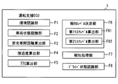
- the driving support ECU 1 provides functions corresponding to the various functional blocks shown in FIG. 3 when the CPU 11 executes the driving support program described above. That is, the driving assistance ECU 1 includes, as functional blocks, an environment recognition unit F1, a vehicle state recognition unit F2, a safe inter-vehicle distance calculation unit F3, an approach degree calculation unit F4, a TTC calculation unit F5, a notification level determination unit F6, and a notification processing unit F7. Is provided.
- the functional blocks provided in the driving support ECU 1 may be realized as hardware using a logic circuit or the like.
- the aspect realized as hardware includes an aspect realized using one or a plurality of ICs. Further, part or all of the functional blocks provided in the driving support ECU 1 may be realized by a combination of software execution by the CPU 11 and hardware members.
- the environment recognition unit F1 is configured to sequentially acquire information on the behavior of the preceding vehicle Pv, the weather, the road surface condition, and the external environment of external brightness. Specifically, the environment recognition unit F1 specifies the inter-vehicle distance from the preceding vehicle Pv, the relative speed Vr, and the traveling speed Vp based on the detection result of the forward monitoring sensor 3. The environment recognition unit F1 corresponds to an inter-vehicle distance acquisition unit.
- the traveling speed Vp of the preceding vehicle Pv may be calculated from the traveling speed Vh of the host vehicle Hv and the relative speed Vr of the preceding vehicle Pv with respect to the host vehicle Hv.
- the traveling speed Vp of the preceding vehicle Pv is specified by referring to the vehicle information packet transmitted from the preceding vehicle Pv among the vehicle information packets received by the narrow area communication unit 4. Also good.
- the association between the other vehicle that is performing the inter-vehicle communication and the preceding vehicle Pv may be performed by a known method such as a method that uses a temporal change in the relative position with respect to the host vehicle Hv.
- the environment recognition unit F1 stores data indicating the inter-vehicle distance from the preceding vehicle Pv, the relative speed Vr of the host vehicle Hv with respect to the preceding vehicle Pv, and the traveling speed Vp of the preceding vehicle Pv in the RAM 13 or the like as preceding vehicle data.
- the environment recognition unit F1 acquires the detection result of the front monitoring sensor 3 at a predetermined time interval (for example, every 100 milliseconds), generates and stores the preceding vehicle data.
- the plurality of preceding vehicle data having different generation points may be sorted and stored in the RAM 13 in chronological order so that the latest preceding vehicle data is at the head, for example.
- the preceding vehicle data that has been stored for a certain period of time may be sequentially discarded.
- the environment recognition unit F1 analyzes the captured image of the front monitoring camera as the front monitoring sensor 3, and thus the road surface state such as whether the road surface is wet, snowy, or a paved road is also detected. Identify.
- the road surface condition derived from the weather such as whether the road surface is wet may be estimated from the detection result of the rain sensor, or may be estimated from the operating state of the wiper.
- the weather information may be estimated from the detection result of the above-described rain sensor and the operating state of the wiper.
- the weather information may be acquired by receiving the weather information distributed from the center.
- the external brightness can be specified from a detection result of an illuminance sensor (not shown) or a captured image of the front monitoring camera.
- the environment recognition unit F1 of the present embodiment acquires vehicle position data indicating the current position of the host vehicle Hv and map data around the host vehicle Hv from the locator 6. Moreover, the other vehicle information provided from the narrow area communication part 4 is acquired, and it distinguishes for every vehicle and preserve
- the vehicle state recognition unit F2 sequentially identifies the state of the host vehicle Hv based on the signal input from the vehicle state sensor 5. For example, the vehicle state recognition unit F2 sequentially specifies the traveling speed Vh of the host vehicle Hv, the steering angle, the accelerator stepping amount, the brake stepping amount, the operating state of the direction indicator, the acceleration acting on the host vehicle Hv, and the like. . Data indicating the traveling speed Vh and the like of the host vehicle Hv is stored in the RAM 13 and the like as host vehicle data. The plurality of host vehicle data having different generation points may be sorted and stored in the RAM 13 in chronological order so that the latest host vehicle data comes first. The own vehicle data that has been stored for a certain period of time may be sequentially discarded.
- the safe inter-vehicle distance calculation unit F3 is configured to calculate a predetermined safe inter-vehicle distance Ls corresponding to the current traveling speed of the host vehicle Hv.
- the safe inter-vehicle distance Ls is a parameter that represents the inter-vehicle distance from the appropriate preceding vehicle Pv corresponding to the traveling speed Vh of the host vehicle Hv.
- the safe inter-vehicle distance Ls for each traveling speed Vh is appropriately designed by a designer or the like. As illustrated in FIG. 4, the safe inter-vehicle distance Ls is designed to increase as the traveling speed Vh of the host vehicle Hv increases. Data indicating the correspondence between the traveling speed and the safe inter-vehicle distance Ls may be designed in advance and stored in the flash memory 12.
- FIG. 4 illustrates a mode in which the safe inter-vehicle distance Ls increases in a curve according to the traveling speed
- the safe inter-vehicle distance Ls may be set to increase linearly or stepwise as the traveling speed Vh increases.
- the safe inter-vehicle distance Ls may be set so as to be set to a larger value as the brightness outside the vehicle compartment and other driving environments such as weather deteriorate. That is, the safe inter-vehicle distance Ls may be set to be determined from other travel environments such as time zone (for example, day / night) and weather, in addition to the travel speed Vh of the host vehicle Hv.
- the safe inter-vehicle distance Ls is a parameter that is determined without depending on the traveling speed Vp of the preceding vehicle Pv (in other words, not used).
- the parameter determined without depending on the traveling speed Vp of the preceding vehicle Pv corresponds to a parameter determined without depending on the relative speed Vr of the host vehicle Hv with respect to the preceding vehicle Pv.
- the approach degree calculation unit F4 divides the safe inter-vehicle distance Ls by the actual inter-vehicle distance (hereinafter, actual inter-vehicle distance) L with the preceding vehicle Pv acquired by the environment recognition unit F1.
- the approach degree D is calculated.
- the approach degree D is a parameter indicating whether or not the inter-vehicle distance between the preceding vehicle Pv and the host vehicle Hv is sufficiently secured.
- the state where the inter-vehicle distance between the preceding vehicle Pv and the host vehicle Hv is insufficient corresponds to a state where the risk of the host vehicle Hv colliding with the preceding vehicle Pv is relatively high. Therefore, the approach degree D functions as a parameter representing the degree of danger that the host vehicle Hv will collide with the preceding vehicle Pv.
- the degree of approach D becomes larger as the actual inter-vehicle distance L is shorter than the safe inter-vehicle distance Ls. That is, the higher the degree of approach D, the higher the degree of risk that the host vehicle Hv will collide with the preceding vehicle Pv. Note that when the actual inter-vehicle distance L coincides with the safe inter-vehicle distance Ls, the approach degree D is 1.
- the approach degree D calculated by the approach degree calculation unit F4 is sequentially provided to the notification level determination unit F6.
- the approach degree calculation unit F4 corresponds to a first index value calculation part, and the approach degree D corresponds to a first risk index value.
- the TTC calculation unit F5 determines that the host vehicle Hv is the preceding vehicle Pv.
- a collision margin time (hereinafter referred to as TTC: Time-To-Collision), which is the remaining time until a collision, is sequentially calculated.
- TTC Time-To-Collision
- a well-known algorithm can be used as the TTC calculation algorithm.
- the actual inter-vehicle distance L may be a value obtained by dividing the actual vehicle distance L by the relative speed Vr of the host vehicle Hv with respect to the preceding vehicle Pv.
- the calculation result of the TTC calculation unit F5 is sequentially provided to the notification level determination unit F6.
- the TTC is a positive value
- the larger the value the smaller the degree of risk that the host vehicle Hv will collide with the preceding vehicle Pv.
- the calculation of the TTC itself may be stopped, or the maximum value that can be set on the program as the TTC (hereinafter referred to as the TTC).
- MAX value may be set.
- the case where the relative speed Vr is a negative value corresponds to the case where the preceding vehicle Pv and the host vehicle Hv are separated from each other.
- the MAX value is set in the TTC.
- the MAX value functions as a value representing infinity for convenience.
- the relative speed Vr is 0, the MAX value is set in the TTC.
- the TTC calculation unit F5 corresponds to a second index value calculation unit, and TTC corresponds to a second risk index value.
- the notification level determination unit F6 indicates the strength of appealing the driver to the risk of a collision with the preceding vehicle Pv based on the proximity D calculated by the proximity calculation unit F4 and the TTC calculated by the TTC calculation unit F5. It is the structure which determines an alerting
- the notification level determination unit F6 includes a first risk level calculation unit F61 and a second risk level calculation unit F62 as finer components (in other words, sub-functions) for determining the notification level.
- the first risk level calculation unit F61 uses factors other than the traveling speed Vp of the preceding vehicle Pv, such as the traveling speed Vh of the host vehicle Hv and the road surface state, based on the approach degree D calculated by the approach degree calculation unit F4. A first risk level is calculated.
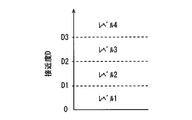
- the first risk level calculation unit F61 determines the first risk level in four stages from 1 to 4.
- Level 1 corresponds to a state where the first risk level is the lowest and there is almost no risk of collision with the preceding vehicle Pv (in other words, it is sufficiently small).
- Level 4 is a state where the first risk level is the highest, and corresponds to a state where the driver should be alerted.
- the first risk level calculation unit F61 determines that the first risk level is higher as the value of the approach degree D is larger as shown in FIG. Specifically, when the approach degree D is less than the predetermined threshold value D1, it is determined as level 1, and when the approach degree D is equal to or greater than the threshold value D1 and less than the threshold value D2, it is determined as level 2. Further, when the degree of approach D is greater than or equal to the threshold D2 and less than the threshold D3, it is determined as level 3. Then, when the approach degree D is equal to or greater than the threshold value D3, it is determined as level 4.
- the threshold value D1 may be designed as appropriate, and is 1.0 here.
- the threshold value D2 may be appropriately designed in a range larger than the threshold value D1, and is set to 1.5 as an example here.
- the threshold value D3 may be appropriately designed in a range larger than the threshold value D2, and is set to 2.0 as an example here.
- the second risk level calculation unit F62 calculates a second risk level based on the relative speed Vr of the host vehicle Hv with respect to the preceding vehicle Pv based on the TTC calculated by the TTC calculation unit F5.
- the second risk level calculation unit F62 determines the second risk level in three stages of levels 1 to 3.
- Level 1 is the state with the lowest second risk level.
- Level 1 corresponds to a state where there is almost no risk of collision with the preceding vehicle Pv (in other words, sufficiently small) if the current relative speed Vr is maintained.
- Level 3 is a state where the second risk level is the highest, and corresponds to a state where the driver should be alerted.
- the second risk level calculation unit F62 determines that the second risk level is higher as the TTC value is smaller as shown in FIG. Specifically, when TTC is equal to or greater than a predetermined threshold T1, it is determined as level 1, and when TTC is less than threshold T1 and equal to or greater than threshold T2, it is determined as level 2. Further, when TTC is less than the threshold value T2, it is determined as level 3.
- the specific value of the threshold value T1 may be appropriately set based on various tests, and is 14 seconds here.
- the configuration in which the threshold T1 is set to 14 seconds is a configuration in consideration of the property that the driver perceives the approach to the preceding vehicle Pv by the increase rate of the visual size of the preceding vehicle Pv.
- TTC is 14 seconds or more
- TTC is 14 seconds or more
- the region where TTC is 14 seconds or more corresponds to a region where it is difficult for the driver to understand the meaning of the alarm even if an alarm is output, and the driver may be bothered.
- the threshold value T2 may be appropriately designed in a range smaller than the threshold value T1, and is set to 5 seconds as an example here.
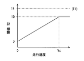
- the threshold value T2 may be dynamically determined according to the traveling speed Vh of the host vehicle Hv. For example, as shown in FIG. 7, the threshold value T ⁇ b> 2 may be set to increase as the traveling speed increases. However, it is assumed that an upper limit value is set for the threshold T2 so that the threshold T2 does not exceed the threshold T1.
- the upper limit value of the threshold value T2 may be appropriately designed in a range smaller than the threshold value T1.
- FIG. 7 shows an aspect in which the upper limit value of the threshold value T2 is set to 10 seconds.
- Vx in FIG. 7 indicates the traveling speed when the threshold value T2 reaches the upper limit value. Vx may be set to 100 km / h, for example.
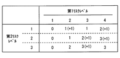
- the notification level determination unit F6 determines the notification level based on the first risk level calculated by the first risk level calculation unit F61 and the second risk level calculated by the second risk level calculation unit F62 as described above. Determine sequentially.
- the notification level determination unit F6 determines the notification level in four stages (that is, a plurality of stages) of levels 0 to 3 so as to include a level where the notification process is not performed.
- Level 0 is a level at which notification processing is not performed.
- Level 1 is a level for notifying the driver that the distance between the preceding vehicle Pv and the inter-vehicle distance is slightly short.
- Level 2 is a level that appeals to the driver more strongly than Level 1 to pay attention to a collision with the preceding vehicle Pv.
- Level 2 is a level for the purpose of prompting the driver to turn his gaze forward even if the driver is looking aside or in a low arousal state.
- Level 3 is a level that appeals to the driver more strongly than Level 2 to pay attention to a collision with the preceding vehicle Pv.
- Level 3 is a level for the purpose of reliably telling the driver of the danger of a collision with the preceding vehicle Pv. Details of the notification mode at each notification level will be described later.
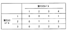
- the notification level determination unit F6 determines the notification level using data indicating a correspondence relationship between the first risk level, the second risk level, and the notification level, for example, as shown in FIG. As illustrated in FIG. 8, the notification level determination unit F6 determines that the notification level is higher as the first risk level is higher and as the second risk level is higher. The operation of the notification level determination unit F6 will be described later separately.
- the notification processing unit F7 is configured to perform processing (that is, notification processing) for notifying the driver of the danger of a collision with the preceding vehicle Pv in a notification mode according to the notification level determined by the notification level determination unit F6. .
- the notification processing unit F7 displays an image (hereinafter referred to as a caution image) that calls attention to the inter-vehicle distance from the preceding vehicle Pv on the display 2B, and sets the peripheral vision device 2C to a predetermined value. Light up gradually until the target brightness is reached. At this time, the final luminance of the peripheral vision device 2C is set to a luminance that does not bother the driver. That is, when the notification level is 1, the notification processing unit F7 dimly lights the peripheral vision device 2C.
- the emission color may be a yellowish green, yellow, orange, or the like that weakens the driver's attention.
- the notification processing unit F7 outputs an alarm sound from the speaker 2A while displaying a caution image on the display 2B.
- the alarm sound that is output when the notification level is 2 is set to a relatively lower sound than the alarm sound that is output when the notification level described later is 3.
- the length of the sound and the repetition interval are also set to relatively long values.
- the sound pressure is also set to a relatively small value.
- the notification processing unit F7 causes the peripheral vision device 2C to blink at a relatively long interval (in other words, slowly).
- the emission color may be the same as when the notification level is 1, or a reddish hue than when the notification level is 1.
- the notification processing unit F7 vibrates the tactile device 2D with a relatively weak vibration pattern.
- the notification processing unit F7 displays a predetermined warning image on the display 2B.
- the warning image is an image that strongly calls attention (that is, warns) about the inter-vehicle distance from the preceding vehicle Pv, and is an image that can be expected to give the driver a sense of crisis more than the warning image. For example, when the background color of the caution image is yellow, an image in which the background color of the warning image is red may be used.
- the notification processing unit F7 outputs an alarm sound from the speaker 2A. Note that the alarm sound to be output when the notification level is 3 is set to a relatively higher sound than the alarm sound output when the notification level is 2.
- the length of the sound and the repetition interval are also set to relatively short values.
- the sound pressure is also set to a relatively strong value.
- the notification processing unit F7 blinks the peripheral vision device 2C at relatively short intervals (in other words, quickly).
- the emission color may be a reddish hue (for example, red) than when the notification level is 2.
- the notification processing unit F7 vibrates the tactile device 2D with a relatively strong vibration pattern.
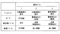
- FIG. 9 is a diagram summarizing the operation mode (in other words, the notification mode) of each notification device for each notification level described above.
- the notification mode for each notification level shown in FIG. 9 is an example, and can be changed as appropriate.
- the higher the notification level the shorter the inter-vehicle distance from the preceding vehicle Pv, in other words, the mode of appealing to the driver that the risk of collision has increased.
- To appeal the predetermined information to the driver strongly corresponds to strengthening visual, tactile and auditory stimuli given to the driver.
- the notification related process is a process for starting a notification process in a mode corresponding to the notification level or canceling (in other words, stopping) the notification process in the matter.
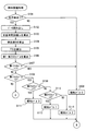
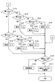
- the flowcharts shown in FIGS. 10 and 11 may be executed sequentially (for example, every 100 milliseconds) while the traveling power source (for example, the ignition power source) of the host vehicle Hv is on.
- step S101 the notification level determination unit F6 determines whether or not a preceding vehicle Pv exists. Whether or not the preceding vehicle Pv exists is determined based on the detection result of the front monitoring sensor 3. If the preceding vehicle Pv exists, an affirmative determination is made in step S101 and the process proceeds to step S102. On the other hand, when the preceding vehicle Pv does not exist, a negative determination is made in step S101, and the process proceeds to step S108.
- step S102 data necessary for calculating the degree of approach D and TTC, such as the traveling speed Vh of the host vehicle Hv, the actual inter-vehicle distance L, and the relative speed Vr of the host vehicle Hv with respect to the preceding vehicle Pv, are read from the RAM 13 and step S102.
- the process moves to S103.
- step S103 the safe inter-vehicle distance calculation unit F3 calculates the safe inter-vehicle distance Ls corresponding to the traveling speed Vh of the host vehicle Hv, and proceeds to step S104.
- step S104 the approach degree calculation unit F4 calculates the approach degree D by dividing the safe inter-vehicle distance Ls calculated in step S103 by the actual inter-vehicle distance L, and proceeds to step S105.
- step S105 the TTC calculation unit F5 calculates TTC by dividing the actual inter-vehicle distance L by the relative speed Vr of the host vehicle Hv with respect to the preceding vehicle Pv, and proceeds to step S106.
- step S106 the first risk level calculation unit F61 calculates the current first risk level based on the approach degree D calculated in step S104. Further, the second risk level calculation unit F62 calculates the current second risk level based on the TTC calculated in step S105. When these arithmetic processes are completed, the process proceeds to step S107.
- step S107 the notification level determination unit F6 determines whether or not the current first risk level is 1. If the first risk level is 1, an affirmative determination is made in step S107 and the process proceeds to step S108. On the other hand, when the first risk level is not 1, a negative determination is made in step S107, and the process proceeds to step S109. In step S108, the notification level determination unit F6 sets the notification level to 0, and proceeds to step S126.
- step S109 the notification level determination unit F6 determines whether or not the current first risk level is 2. If the first risk level is 2, an affirmative determination is made in step S109 and the process proceeds to step S110. On the other hand, when the first risk level is not 2, a negative determination is made in step S109, and the process proceeds to step S115.
- step S110 the notification level determination unit F6 determines whether or not the current second risk level is 1. If the second risk level is 1, an affirmative determination is made in step S110 and the process proceeds to step S111. On the other hand, when the second risk level is not 1, a negative determination is made in step S110, and the process proceeds to step S112. In step S111, the notification level determination unit F6 sets the notification level to 0, and proceeds to step S126.
- step S112 the notification level determination unit F6 determines whether or not the current second risk level is 2. If the second risk level is 2, an affirmative decision is made in step S112 and the process proceeds to step S113. On the other hand, if the second risk level is not 2, that is, if the second risk level is 3, a negative determination is made in step S112 and the process proceeds to step S114. In step S113, the notification level determination unit F6 sets the notification level to 1, and proceeds to step S126. In step S114, the notification level determination unit F6 sets the notification level to 2, and proceeds to step S126.
- step S115 the notification level determination unit F6 determines whether or not the current first risk level is 3. If the first risk level is 3, an affirmative determination is made in step S115 and the process proceeds to step S116. On the other hand, if the first risk level is not 3, that is, if the first risk level is 4, a negative determination is made in step S115 and the process proceeds to step S121.
- step S116 the notification level determination unit F6 determines whether or not the current second risk level is 1. If the second risk level is 1, an affirmative determination is made in step S116 and the process proceeds to step S117. On the other hand, when the second risk level is not 1, a negative determination is made in step S116, and the process proceeds to step S118. In step S117, the notification level determination unit F6 sets the notification level to 1, and proceeds to step S126.
- step S118 the notification level determination unit F6 determines whether or not the current second risk level is 2. If the second risk level is 2, an affirmative determination is made in step S118 and the process proceeds to step S119. On the other hand, if the second risk level is not 2, that is, if the second risk level is 3, a negative determination is made in step S119 and the process proceeds to step S120. In step S119, the notification level determination unit F6 sets the notification level to 1, and proceeds to step S126. In step S120, the notification level determination unit F6 sets the notification level to 2, and proceeds to step S126.
- step S121 the notification level determination unit F6 determines whether or not the current second risk level is 1. If the second risk level is 1, an affirmative determination is made in step S121 and the process proceeds to step S122. On the other hand, when the second risk level is not 1, a negative determination is made in step S121, and the process proceeds to step S123. In step S122, the notification level determination unit F6 sets the notification level to 1, and proceeds to step S126.
- step S123 the notification level determination unit F6 determines whether or not the current second risk level is 2. If the second risk level is 2, an affirmative determination is made in step S123 and the process proceeds to step S124. On the other hand, when the second risk level is not 2, that is, when the second risk level is 3, a negative determination is made in step S123, and the process proceeds to step S125. In step S124, the notification level determination unit F6 sets the notification level to 2, and proceeds to step S126. In step S125, the notification level determination unit F6 sets the notification level to 3, and proceeds to step S126.
- step S126 the notification processing unit F7 determines whether or not the notification level determined by the above processing is 1 or more. If the notification level is 1 or higher, an affirmative determination is made in step S126 and the process proceeds to step S127. On the other hand, when the notification level is 0, a negative determination is made in step S126, and the process proceeds to step S128.
- the case where the notification level is 1 or more corresponds to the case where the notification process needs to be performed, and the case where the notification level is 0 corresponds to the case where the notification process does not need to be performed. That is, the process of step S126 corresponds to a process of determining whether or not the notification process needs to be started / continued.
- step S127 the notification processing unit F7 performs notification processing in a notification mode according to the current notification level. For example, when the notification process has already been performed at the start of this flow and the notification level determined in the previous notification-related process is different from the notification level determined in the current notification-related process The notification mode is changed to the notification level determined this time. In addition, when the notification process is not performed at the start of this flow and the notification level determined by the current notification-related processing is 1 or more, in a mode according to the notification level determined this time The notification process is started.
- the notification level already determined at the start of this flow and the notification level determined in the previous notification-related processing is the same as the notification level determined in the previous notification-related processing. In such a case, the notification process in the mode performed before the start of this flow may be continued.
- step S1208 the notification processing unit F7 stops the notification process. If the notification process is not performed at the start of this flow, the state where the notification process is not executed may be continued.
- the notification level that determines the mode of the notification process is determined by two parameters, the first risk level and the second risk level.
- the first risk level is determined according to the approach degree D calculated without using the traveling speed Vp of the preceding vehicle Pv. Therefore, the first risk level is a parameter calculated without using the traveling speed Vp of the preceding vehicle Pv.
- the second risk level is determined according to the TTC. Since the TTC is calculated based on the relative speed Vr of the host vehicle Hv with respect to the preceding vehicle Pv, the second risk level uses the relative speed Vr of the host vehicle Hv with respect to the preceding vehicle Pv, that is, the traveling speed Vp of the preceding vehicle Pv.
- This parameter is calculated by That is, according to the configuration of the present embodiment, the notification level is calculated using the first risk level calculated without using the traveling speed Vp of the preceding vehicle Pv and the traveling speed Vp of the preceding vehicle Pv. Determined using both risk levels.
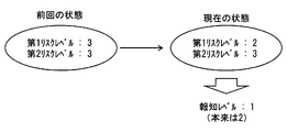
- the relative speed Vr of the host vehicle Hv with respect to the preceding vehicle Pv decreases. Since the second risk level is a parameter determined according to the relative speed Vr, when the driver performs a deceleration operation, the second risk level also decreases in response to the deceleration operation.
- the notification level is also determined by the second risk level, if the second risk level decreases, the notification level can also decrease.
- the notification mode of the notification process is changed to a relatively weak mode, or the notification process itself is stopped. Therefore, even in a situation where the inter-vehicle distance has not changed so much, the notification mode can change based on the driver's deceleration operation, so that the notification in the same notification mode continues to be implemented, which causes trouble for the driver. Fear can be reduced.
- the second risk level increases as the relative speed Vr increases even when the inter-vehicle distance has not yet changed significantly, and the notification level can increase.
- the notification mode of the notification process also changes to a relatively strong notification mode. Therefore, according to the above configuration, it is possible to reduce the possibility that the driver will notice that sudden braking of the preceding vehicle Pv is delayed. That is, according to the said structure, a risk can be alert
- a configuration for determining a notification level based only on TTC (hereinafter, a first assumed configuration) is also assumed.
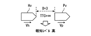
- the TTC becomes a relatively large value when the relative speed Vr is sufficiently small. If the actual inter-vehicle distance L is short even if TTC is large, the driver has a short time margin for performing an operation for avoiding a collision with the preceding vehicle Pv when the preceding vehicle Pv suddenly brakes at the next moment. It can be said that the risk of collision is potentially high. That is, in the first assumed configuration, the notification process cannot be performed in a manner that takes into account the potential danger of a collision.
- the present embodiment not only the TTC but also the approach degree D is taken into consideration to determine the notification level.
- a notification level that reveals a potential danger that may exist even when TTC is large is determined. Therefore, as shown in FIG. 13, when the actual inter-vehicle distance L is very small, a relatively high notification level is set. As a result, the risk of collision with the preceding vehicle Pv can be more strongly appealed to the driver.
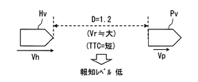
- a configuration (hereinafter referred to as a second assumed configuration) in which the notification level is determined based only on the approach degree D as in Patent Document 1 is also assumed.
- the TTC is a relatively small value when the relative speed Vr is large. If the TTC is small, it can be said that the risk of collision is potentially high because the driver has a short time margin for performing an operation for avoiding a collision with the preceding vehicle Pv.
- the notification process may not be performed in a manner that takes into account the potential danger of a collision.
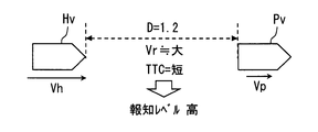
- the notification level is determined by revealing a risk that does not appear only by the degree of proximity D. Therefore, as shown in FIG. 15, even if the degree of approach D is not so high, if the TTC is relatively short, a relatively high notification level is set. As a result, the risk of a collision with the preceding vehicle Pv can be strongly appealed to the driver.
- the notification level determination unit F6 may determine the notification level in consideration of the driver's state, for example, whether or not the driver is in an aside state.
- the driving support system 100 includes a driving support ECU 1, a notification device 2, a front monitoring sensor 3, a narrow communication unit 4, a vehicle state sensor 5, a locator 6, and a driver state sensor 7. I have.
- Driver state sensor 7 is a sensor that detects the state of the driver.
- the driver state includes, for example, the driver's face direction, line-of-sight direction, eyelid opening, body direction (in other words, sitting posture), handle gripping state, and the like.
- the driver's biological information such as heart rate, blood pressure, cardiac potential, pulse wave, sweating volume, body temperature, respiratory rhythm, and respiratory depth also functions as information indicating the driver's state. Further, whether or not the driver is talking with a passenger or the like is also included in the driver state.
- a driver state sensor 7 for example, a driver camera arranged so as to image the face of the driver, a microphone, a handle grip sensor, a back pressure sensor, a seat pressure sensor, a biological information sensor, or the like is adopted.
- the driver camera is a camera installed so as to take an image of the driver's face.
- the driver camera may be realized using, for example, a near-infrared light source, a near-infrared camera, and a control unit that controls them.
- the driver camera performs a well-known image recognition process on the image captured by the near-infrared camera, so that the head position of the occupant (ie, driver) in the driver's seat, the driver's face orientation, the line-of-sight direction, and the eyelid opening The degree and the like are detected sequentially.
- the driver camera may be placed at an appropriately designed position such as the steering column cover or the part of the instrument panel facing the driver's seat so as to capture the face area of the occupant seated in the driver's seat. That's fine.
- the handle grip sensor is a pressure sensor provided on the handle, and the back pressure sensor is a pressure sensor sheet arranged to detect the distribution of pressure acting on the backrest portion of the driver's seat.
- the seat pressure sensor is a pressure sensor seat disposed on the seating surface of the driver seat, and detects the distribution of pressure acting on the seating surface of the driver seat.
- the biological information sensor is, for example, a heart rate sensor that measures a heart rate. Sensors for detecting blood pressure, cardiac potential, pulse wave, sweat volume, body temperature, respiratory rhythm, and respiratory depth are also included in the biological information sensor.
- the driving support system 100 includes at least one of the various sensors described above as the driver state sensor 7.
- the driving support system 100 includes a driver camera and a heart rate sensor as the driver state sensor 7.
- Each of the driver camera and the heart rate sensor as the driver state sensor 7 sequentially provides the driving support ECU 1 with data indicating the detection result. That is, the driver assistance ECU 1 is provided with the driver's head posture, the driver's face orientation, the line-of-sight direction, the eyelid opening degree, the heart rate, and the like.
- the driving support ECU 1 in the first modification includes a driver state recognition unit F8 in addition to various functional blocks as shown in FIG.
- the driver state recognition unit F8 is configured to sequentially specify the driver state based on the detection result of the driver state sensor 7 and the detection result of the vehicle state sensor 5.
- the driver state recognition unit F8 is realized by executing software by the CPU 11.
- the driver state recognition unit F8 may be realized as hardware using an IC or the like.
- the driver state recognition unit F8 determines, for example, whether or not the driver is looking aside without looking at the front of the vehicle, based on the driver's face orientation and line-of-sight direction specified by the driver camera. For example, when the driver's face is directed in a direction in which an angle with the vehicle front direction is 20 degrees or more, it is determined that the driver is looking aside.
- the driver is dozing from the degree of opening of the driver's heel. Further, even when the driver is not in a dozing state, it is determined whether or not the driver is in a low arousal state in which the driver's consciousness level is lowered based on a temporal change such as the degree of opening of the eyelids. In addition, it is determined whether or not the state is a random state based on the steering angle fluctuation, the gaze fluctuation, or the like.
- the method of determining the driver's state such as a side-by-side state, a dozing state, a low arousal state, and a vague state is not limited to the method described above. A well-known method can be adopted.
- the driver state recognition unit F8 determines that the driver is in an abnormal state when it is determined that the driver corresponds to any of the aside state, the dozing state, the low arousal state, and the loose state, and the driver is in an abnormal state.
- An abnormal flag Fd indicating whether or not is set to 1.
- the abnormality flag Fd is set to 0.
- the state where the abnormality flag Fd is set to 1 corresponds to the state where the abnormality flag Fd is set to ON.
- the state where the abnormality flag Fd is set to 0 corresponds to the state where the abnormality flag Fd is set to off.
- the driver state recognition unit F8 determines all the states of a look-ahead state, a dozing state, a low arousal state, and a casual state.
- the present invention is not limited to this. You may be comprised so that only a part of a look-a-side state, a dozing state, a low arousal state, and a casual state may be determined.
- the set value of the abnormality flag Fd is referred to by the notification level determination unit F6 (particularly, the first risk level calculation unit F61).
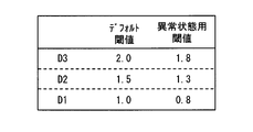
- the first risk level calculation unit F61 in Modification 1 calculates the first risk level using not only the proximity D calculated by the proximity calculation unit F4 but also the determination result of the driver state recognition unit F8. Specifically, the first risk level calculation unit F61 of the first modification includes a default threshold and an abnormal condition threshold as thresholds D1 to D3 for calculating the first risk level.
- the default threshold value is a threshold value used as the threshold values D1 to D3 when the driver state recognition unit F8 determines that the driver is not in an abnormal state (in other words, a normal state).
- the abnormal state threshold is a threshold used as the thresholds D1 to D3 when the driver state recognition unit F8 determines that the driver is in an abnormal state.
- the default threshold value may be set to the same value as in the above-described embodiment.
- the abnormal state threshold is set to a value relatively smaller than the default threshold.
- the threshold value for abnormal state is set to a value smaller by 0.2 than the default threshold value.
- the first risk level is easily determined to be high.
- the fact that the first risk level is easily determined is equivalent to the fact that the notification level is easily determined.
- the timing at which the notification processing is started and the timing at which the notification processing in a relatively strong notification mode is executed are advanced. That is, by setting the abnormal condition threshold value to a value relatively smaller than the default threshold value, the timing at which the notification process is started or the timing at which the notification process in a relatively strong notification mode is executed can be advanced. it can.
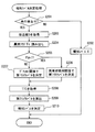
- FIG. 19 is a flowchart for explaining a process in which the notification level determination unit F6 determines the notification level (hereinafter, notification level determination process).
- the flowchart shown in FIG. 19 may be executed sequentially while the traveling power source of the host vehicle Hv is on, as in the notification-related processing of the embodiment.
- the notification level determination process illustrated in FIG. 19 corresponds to a process in which the process executed by the notification level determination unit F6 is extracted from the notification-related processes performed by the driving support ECU 1. Each step provided in the flowchart shown in FIG. 19 is executed by the notification level determination unit F6.
- step S201 it is determined whether or not a preceding vehicle Pv exists.
- a negative determination is made in step S201, and the process proceeds to step S202.
- an affirmative determination is made in step S201 and the process proceeds to step S202.
- step S202 the notification level is set to 0 and this flow ends.
- step S203 the approach degree D calculated by the approach degree calculation unit F4 is acquired, and the process proceeds to step S204.
- step S204 the set value of the abnormality flag Fd is read, and the process proceeds to step S205.
- step S205 it is determined whether or not the abnormality flag Fd is set to 1. If the abnormality flag Fd is set to 1, an affirmative determination is made in step S205 and the process proceeds to step S206. On the other hand, if the abnormality flag Fd is not set to 1, that is, if the abnormality flag Fd is set to 0, a negative determination is made in step S205 and the process proceeds to step S207.
- step S206 the first risk level calculation unit F61 calculates a first risk level corresponding to the degree of approach D acquired in step S203 using a predetermined abnormal state threshold instead of the default threshold, and then proceeds to step S208. Move.
- step S207 the first risk level corresponding to the degree of approach D acquired in step S203 is calculated using the default threshold, and the process proceeds to step S208.
- step S208 the TTC calculated by the TTC calculation unit F5 is acquired, and the process proceeds to step S209.
- step S209 the second risk level corresponding to the TTC acquired in step S208 is calculated, and the process proceeds to step S210.
- step S210 the notification level is determined based on the first risk level and the second risk level determined by the above processing, and this flow is terminated.
- the notification processing unit F7 performs the notification processing or stops the notification processing according to the determined notification level.
- ⁇ Summary of Modification 1> when the driver is in a predetermined abnormal state such as a look-aside state, a threshold value set so that the first risk level is relatively easily determined to be a high level is used. Determine the first risk level. According to such a configuration, the timing at which the notification processing is started and the timing at which the notification processing in a relatively strong notification mode is executed are advanced. As a result, it can be expected that the timing for returning the driver from the abnormal state to the normal state or for allowing the driver to confirm the front is advanced.
- a mode is disclosed in which the notification level is calculated according to the same rules as when the driver is determined to be in a normal state even when the driver is determined to be in an abnormal state.
- the notification level determination rule may be set so that the notification level is determined to be higher than when the driver is determined to be in a normal state. good.
- the notification level is determined using the correspondence table shown in FIG. 8, while when the driver is determined to be in an abnormal state, it is shown in FIG. The notification level is determined using the correspondence table.
- the numbers in parentheses in FIG. 20 represent the difference from the notification level set when it is determined that the driver is in a normal state. That is, in the example shown in FIG. 20, when the first risk level is 2 and the second risk level is 1, and it is determined that the driver is in an abnormal state, the driver is in a normal state. This indicates that the notification level is determined to be one step higher than the case where it is determined that there is. If the first risk level is 4 and the second risk level is 1, or if the first risk level is 3 and the second risk level is 2, the first risk level is 4 and the second risk level is 2, The same applies when the first risk level is 3 and the second risk level is 3.
- the driver when the driver is in an abnormal state, not only the start timing of the notification process is advanced, but also the stimulus output by the notification process is strengthened. According to such an aspect, the driver can easily recognize that there is a risk of collision with the preceding vehicle. Naturally, if the driver recognizes the danger of a collision with the preceding vehicle, it can be expected that an operation for reducing the danger of the collision, such as stopping the acceleration operation or executing the deceleration operation, is performed. That is, according to the configuration of the second modification, it can be expected that the safety is further improved.
- Modification 3 In Modification 1 and Modification 2 described above, when the driver state recognition unit F8 determines that the driver is in an abnormal state, the first risk level is higher than when the driver is determined to be in a normal state.
- the thresholds D1 to D3 for determining the first risk level are changed so as to be easily determined to be high, the present invention is not limited to this.
- the threshold values T1 to T2 may be changed so that the second risk level is determined to be higher than when the driver is determined to be in a normal state.
- a default threshold value applied when the driver state is determined by the driver state recognition unit F8 to be in a normal state, and a driver being in an abnormal state An abnormal state threshold value to be applied when the determination is made may be prepared, and these may be properly used according to the determination result of the driver state recognition unit F8.
- the abnormal condition threshold for determining the second risk level may be set to a value larger than the default threshold.
- the abnormal condition threshold for determining the second risk level is a value obtained by multiplying the default threshold by a predetermined coefficient (for example, 1.2) larger than 1 or a predetermined positive number (for example, 1 second).
- the value may be set as follows. According to such a configuration, when the driver state recognition unit F8 determines that the driver is in an abnormal state, the second risk level is easily determined higher than when the driver is determined to be in a normal state. Become. As a result, when the driver is in an abnormal state, the notification level is easily determined to be higher than when the driver is in a normal state.
- the notification level determination unit F6 may determine the notification level in consideration of the state of the notification level driver in view of the state transition of the host vehicle Hv.
- the state transition of the host vehicle Hv here refers to a change in the first risk level or a change in the second risk level.
- a first modification such a configuration will be described as a first modification.
- the notification level determination unit F6 in Modification 4 stores the determined first risk level and second risk level in the RAM 13 as previous state information.
- the notification level determination unit F6 in Modification 4 stores the determined first risk level and second risk level in the RAM 13 as previous state information.
- the first and second risk levels stored in the RAM 13 as the previous state information are referred to, and the first risk level is It is determined whether it has improved and whether the second risk level has improved.
- the notification level determination unit F6 determines the notification level to be lower than the original notification level determined from the current first and second risk levels.
- the case where the first risk level is improved is a case where the first risk level calculated this time is lower than the first risk level calculated last time.
- the case where the second risk level is improved is a case where the second risk level calculated this time is lower than the first risk level calculated last time.
- the notification level is set to 0.
- the notification level is also set to 0 when the second risk level is lowered from 2 to 1.
- the original notification level is 1 when the first risk level is 3 and the second risk level is 1.
- the notification level is set to 0.
- the notification level is similarly set to 0 when the second risk level is lowered from 3 to 2.
- the original notification level when the first risk level is 2 and the second risk level is 2 is 1.
- the notification level is set to 1.
- the original notification level when the first risk level is 2 and the second risk level is 3 is 2.
- the improvement in the first risk level and the second risk level means that the positional relationship between the host vehicle Hv and the preceding vehicle Pv has shifted to a safer state due to the driver's deceleration operation or the like.
- the driver is bothered by weakening the manner of the notification processing or stopping the notification processing early. Fear can be reduced.
- setting the notification level to a level lower than the original notification level based on the improvement of the first risk level is based on the fact that the value of the approach degree D has changed to a smaller value. This corresponds to setting the level lower than the original notification level. Since the degree of approach D is a parameter that indicates a safer state as it is smaller, transition of the value of the degree of approach D to a smaller value means a transition to a safer state.
- setting the notification level to a level lower than the original notification level based on the improvement of the second risk level sets the notification level to the original level based on the fact that the TTC value has changed to a larger value. This corresponds to setting a level lower than the notification level. Since TTC is a parameter that means a safer state as it is larger, transition of the TTC value to a larger value means that the TTC has shifted to a safer state.
- the index used for calculating the second risk level (in other words, the second risk index value) is not limited to the TTC.
- the second risk level calculation unit F62 may calculate the second risk level using the reciprocal of TTC.
- the second risk level may be calculated using TTC2nd considering relative speed and relative acceleration.
- the second risk level may be calculated based on a known risk index using the traveling speed Vp of the preceding vehicle Pv, such as a margin margin (MTC: Margin-To-Collision), in addition to the risk index described above. it can.
- MTC Margin-To-Collision
- the first risk level calculation unit F61 may calculate the first risk level using a safety margin time described below as a first risk index value.
- the safety margin time is a value obtained by subtracting the reaction delay time, the reaction time, and the required inter-vehicle time from the current inter-vehicle time.
- the inter-vehicle time is a value obtained by dividing the actual inter-vehicle distance L by the traveling speed Vh of the host vehicle Hv.
- the reaction delay time is a delay time required for the driver to notice that a risk event such as sudden braking of the preceding vehicle Pv has occurred.
- the reaction delay time is preset. Note that the reaction delay time may be adjusted to a long value during a dull driving or a side-viewing driving.
- the reaction time is the time taken from when the driver notices the occurrence of the risk event until the braking operation is started, and is a parameter determined by the driver's driving skill, age, and the like.
- the reaction time is preset.
- the required inter-vehicle time is a time required from when the driver starts the braking operation until the vehicle stops, and is a parameter determined by road surface conditions, vehicle type performance, and the like.
- the required inter-vehicle time is set in advance. The necessary inter-vehicle time may be adjusted so as to increase as the traveling speed Vh increases. Even if such a safety margin time is used instead of the degree of approach D, the above-described effects can be obtained.
- each section is expressed as S101, for example.
- each section can be divided into a plurality of subsections, while a plurality of sections can be combined into one section.
- each section configured in this manner can be referred to as a device, module, or means.
Landscapes
- Engineering & Computer Science (AREA)
- Transportation (AREA)
- Mechanical Engineering (AREA)
- Automation & Control Theory (AREA)
- Chemical & Material Sciences (AREA)
- Combustion & Propulsion (AREA)
- Human Computer Interaction (AREA)
- Traffic Control Systems (AREA)
Priority Applications (1)
| Application Number | Priority Date | Filing Date | Title |
|---|---|---|---|
| US16/514,190 US10723365B2 (en) | 2017-03-24 | 2019-07-17 | Driving assistance device |
Applications Claiming Priority (2)
| Application Number | Priority Date | Filing Date | Title |
|---|---|---|---|
| JP2017-059729 | 2017-03-24 | ||
| JP2017059729A JP6597690B2 (ja) | 2017-03-24 | 2017-03-24 | 運転支援装置 |
Related Child Applications (1)
| Application Number | Title | Priority Date | Filing Date |
|---|---|---|---|
| US16/514,190 Continuation US10723365B2 (en) | 2017-03-24 | 2019-07-17 | Driving assistance device |
Publications (1)
| Publication Number | Publication Date |
|---|---|
| WO2018173455A1 true WO2018173455A1 (ja) | 2018-09-27 |
Family
ID=63584393
Family Applications (1)
| Application Number | Title | Priority Date | Filing Date |
|---|---|---|---|
| PCT/JP2018/001889 Ceased WO2018173455A1 (ja) | 2017-03-24 | 2018-01-23 | 運転支援装置 |
Country Status (3)
| Country | Link |
|---|---|
| US (1) | US10723365B2 (enExample) |
| JP (1) | JP6597690B2 (enExample) |
| WO (1) | WO2018173455A1 (enExample) |
Cited By (2)
| Publication number | Priority date | Publication date | Assignee | Title |
|---|---|---|---|---|
| CN111994073A (zh) * | 2020-07-22 | 2020-11-27 | 北京交通大学 | 一种自动紧急制动控制方法 |
| US12049219B2 (en) | 2019-06-25 | 2024-07-30 | Valeo Vision | Method for preventing a collision between a motor vehicle and an object, using a light module |
Families Citing this family (43)
| Publication number | Priority date | Publication date | Assignee | Title |
|---|---|---|---|---|
| CN108583571A (zh) * | 2018-04-28 | 2018-09-28 | 深圳市商汤科技有限公司 | 碰撞控制方法及装置、电子设备和存储介质 |
| JP2020064554A (ja) * | 2018-10-19 | 2020-04-23 | 株式会社デンソー | 運転ガイドシステム |
| US11961395B2 (en) * | 2018-12-12 | 2024-04-16 | Nec Corporation | Driving assistance device, driving assistance method, and storage medium in which program is stored |
| JP6708273B1 (ja) * | 2019-02-08 | 2020-06-10 | スズキ株式会社 | 車両用対話装置 |
| CN109808492B (zh) * | 2019-02-15 | 2020-06-02 | 辽宁工业大学 | 一种车载雷达预警装置及预警方法 |
| CN111605557B (zh) * | 2019-02-25 | 2021-12-21 | 郑州宇通客车股份有限公司 | 一种基于驾驶安全评价的车辆控制方法及装置 |
| CN113614807B (zh) * | 2019-03-15 | 2023-09-19 | 本田技研工业株式会社 | 车辆通信装置和存储有程序的计算机可读非暂时性存储介质 |
| WO2020188942A1 (ja) * | 2019-03-15 | 2020-09-24 | 本田技研工業株式会社 | 車両用コミュニケーション装置及びプログラム |
| JP7148453B2 (ja) * | 2019-04-19 | 2022-10-05 | トヨタ自動車株式会社 | 運転支援システム |
| JP7402624B2 (ja) * | 2019-06-24 | 2023-12-21 | 日野自動車株式会社 | 自動停車システム |
| US11565653B2 (en) | 2020-01-03 | 2023-01-31 | Aptiv Technologies Limited | Vehicle occupancy-monitoring system |
| EP3845431B1 (en) * | 2020-01-06 | 2024-08-07 | Aptiv Technologies AG | Driver-monitoring system |
| CN113370990B (zh) * | 2020-03-10 | 2025-11-07 | 深圳引望智能技术有限公司 | 驾驶辅助方法和驾驶辅助装置 |
| JP2021144419A (ja) * | 2020-03-11 | 2021-09-24 | いすゞ自動車株式会社 | 安全運転判定装置 |
| JP7432412B2 (ja) * | 2020-03-18 | 2024-02-16 | 株式会社デンソーテン | 車載装置および危険車両検出方法 |
| CN111361506A (zh) * | 2020-03-26 | 2020-07-03 | 江铃汽车股份有限公司 | 一种提示灯控制方法、系统、可读存储介质及车辆 |
| CN113511170B (zh) * | 2020-04-10 | 2022-10-25 | 采埃孚汽车科技(上海)有限公司 | 通过汽车安全带增强司乘人员安全性的系统和方法 |
| JP7747733B2 (ja) * | 2020-04-10 | 2025-10-01 | ゼットエフ・オートモーティブ・テクノロジーズ(シャンハイ)カンパニー,リミテッド | 車両の道路両立性を改善するための安全システム、車両安全システムおよび装置、方法、ならびに媒体 |
| CN113511159B (zh) * | 2020-04-10 | 2023-01-31 | 采埃孚汽车科技(上海)有限公司 | 通过气囊增强司乘人员安全性的系统和方法 |
| DE102020205674A1 (de) | 2020-05-05 | 2021-11-11 | Volkswagen Aktiengesellschaft | Verfahren, Computerprogramm und Vorrichtung zur Wiedergabe von Benachrichtigungen in einem Fahrzeug |
| CN113715837B (zh) * | 2020-05-25 | 2023-10-20 | 沃尔沃汽车公司 | 车辆安全隐患管理系统和方法 |
| KR20210150922A (ko) * | 2020-06-04 | 2021-12-13 | 현대모비스 주식회사 | 차량의 주행 제어 시스템 및 방법 |
| CN112046472A (zh) * | 2020-09-11 | 2020-12-08 | 中国第一汽车股份有限公司 | 一种车辆避撞方法、装置、车辆及存储介质 |
| KR20220082968A (ko) * | 2020-12-10 | 2022-06-20 | 현대자동차주식회사 | 차량 운전자의 시야 보조 방법 및 그 보조 장치 |
| JP7510116B2 (ja) * | 2020-12-17 | 2024-07-03 | トヨタ自動車株式会社 | 車両運転支援装置 |
| JP7653073B2 (ja) * | 2021-01-20 | 2025-03-28 | スズキ株式会社 | 車両用警報装置 |
| JP2022140032A (ja) * | 2021-03-12 | 2022-09-26 | 本田技研工業株式会社 | 運転支援装置及び車両 |
| CN115140062B (zh) * | 2021-03-29 | 2025-06-20 | 本田技研工业株式会社 | 驾驶辅助装置 |
| EP4112411B1 (en) * | 2021-07-01 | 2024-03-27 | Zenseact AB | Estimation of accident intensity for vehicles |
| US11639181B2 (en) * | 2021-09-29 | 2023-05-02 | Nissan North America, Inc. | Lead vehicle braking warning system |
| CN114194197B (zh) * | 2021-12-08 | 2023-12-19 | 中科创达软件股份有限公司 | 一种危险驾驶预警方法、装置、设备和相关系统 |
| JP7316593B2 (ja) * | 2021-12-15 | 2023-07-28 | パナソニックIpマネジメント株式会社 | 路側機、及び、暴走車両被害軽減システム |
| JP7813145B2 (ja) * | 2022-01-24 | 2026-02-12 | 株式会社Subaru | 車両の運転支援装置 |
| CN114312813B (zh) * | 2022-03-04 | 2022-07-29 | 苏州挚途科技有限公司 | 切入自车道的车辆确认方法、装置和电子设备 |
| US11718314B1 (en) | 2022-03-11 | 2023-08-08 | Aptiv Technologies Limited | Pedestrian alert system |
| JP7422177B2 (ja) * | 2022-03-31 | 2024-01-25 | 本田技研工業株式会社 | 交通安全支援システム |
| JP2023174313A (ja) * | 2022-05-27 | 2023-12-07 | トヨタ自動車株式会社 | 車両用制御装置、車両、車両用制御方法およびプログラム |
| WO2024252912A1 (ja) * | 2023-06-05 | 2024-12-12 | ソニーセミコンダクタソリューションズ株式会社 | 情報処理装置、情報処理方法、および情報処理システム |
| CN117246321A (zh) * | 2023-09-14 | 2023-12-19 | 武汉科技大学 | 一种多场景下的前方危险目标检测方法及aeb控制策略 |
| TWI881657B (zh) * | 2024-01-09 | 2025-04-21 | 緯創資通股份有限公司 | 車間網路虛假風險警告識別方法及使用所述方法的車載電子裝置 |
| WO2025234088A1 (ja) * | 2024-05-10 | 2025-11-13 | Astemo株式会社 | 車両用振動発生装置 |
| CN118514686B (zh) * | 2024-05-24 | 2025-12-30 | 奇瑞汽车股份有限公司 | 一种基于毫米波雷达的自动紧急制动方法及系统 |
| CN120942375B (zh) * | 2025-10-20 | 2025-12-16 | 深圳市众鸿科技股份有限公司 | 一种驾驶员接管监测方法、装置及车辆 |
Citations (7)
| Publication number | Priority date | Publication date | Assignee | Title |
|---|---|---|---|---|
| JPH10116400A (ja) * | 1996-10-11 | 1998-05-06 | Honda Access Corp | 車両の走行履歴記録システム |
| JPH1172561A (ja) * | 1997-08-28 | 1999-03-16 | Nissan Motor Co Ltd | 車間距離警報装置 |
| JP2001167397A (ja) * | 1999-12-08 | 2001-06-22 | Honda Motor Co Ltd | 車両用運転状況監視装置 |
| JP2004164187A (ja) * | 2002-11-12 | 2004-06-10 | Nissan Motor Co Ltd | 車両用報知装置 |
| JP2010128669A (ja) * | 2008-11-26 | 2010-06-10 | Toyota Central R&D Labs Inc | 運転支援装置及びプログラム |
| WO2012157633A1 (ja) * | 2011-05-18 | 2012-11-22 | 本田技研工業株式会社 | 走行制御装置 |
| JP2015162005A (ja) * | 2014-02-26 | 2015-09-07 | 富士重工業株式会社 | 自動運転システム |
Family Cites Families (6)
| Publication number | Priority date | Publication date | Assignee | Title |
|---|---|---|---|---|
| JPH1096777A (ja) | 1996-09-24 | 1998-04-14 | Honda Access Corp | 車両の衝突警報システム |
| DE102007013685A1 (de) | 2007-03-22 | 2008-09-25 | Robert Bosch Gmbh | Kollisionswarnvorrichtung für Kraftfahrzeuge |
| JP2012144053A (ja) * | 2011-01-06 | 2012-08-02 | Denso Corp | アクセル・ブレーキ踏み間違い判定装置 |
| CN104487308B9 (zh) * | 2012-07-24 | 2017-07-07 | 丰田自动车株式会社 | 驾驶辅助装置 |
| JP2014211756A (ja) * | 2013-04-18 | 2014-11-13 | トヨタ自動車株式会社 | 運転支援装置 |
| JP6246392B2 (ja) * | 2014-12-09 | 2017-12-13 | 三菱電機株式会社 | 衝突リスク算出装置、衝突リスク表示装置、車体制御装置 |
-
2017
- 2017-03-24 JP JP2017059729A patent/JP6597690B2/ja active Active
-
2018
- 2018-01-23 WO PCT/JP2018/001889 patent/WO2018173455A1/ja not_active Ceased
-
2019
- 2019-07-17 US US16/514,190 patent/US10723365B2/en active Active
Patent Citations (7)
| Publication number | Priority date | Publication date | Assignee | Title |
|---|---|---|---|---|
| JPH10116400A (ja) * | 1996-10-11 | 1998-05-06 | Honda Access Corp | 車両の走行履歴記録システム |
| JPH1172561A (ja) * | 1997-08-28 | 1999-03-16 | Nissan Motor Co Ltd | 車間距離警報装置 |
| JP2001167397A (ja) * | 1999-12-08 | 2001-06-22 | Honda Motor Co Ltd | 車両用運転状況監視装置 |
| JP2004164187A (ja) * | 2002-11-12 | 2004-06-10 | Nissan Motor Co Ltd | 車両用報知装置 |
| JP2010128669A (ja) * | 2008-11-26 | 2010-06-10 | Toyota Central R&D Labs Inc | 運転支援装置及びプログラム |
| WO2012157633A1 (ja) * | 2011-05-18 | 2012-11-22 | 本田技研工業株式会社 | 走行制御装置 |
| JP2015162005A (ja) * | 2014-02-26 | 2015-09-07 | 富士重工業株式会社 | 自動運転システム |
Cited By (2)
| Publication number | Priority date | Publication date | Assignee | Title |
|---|---|---|---|---|
| US12049219B2 (en) | 2019-06-25 | 2024-07-30 | Valeo Vision | Method for preventing a collision between a motor vehicle and an object, using a light module |
| CN111994073A (zh) * | 2020-07-22 | 2020-11-27 | 北京交通大学 | 一种自动紧急制动控制方法 |
Also Published As
| Publication number | Publication date |
|---|---|
| JP2018163482A (ja) | 2018-10-18 |
| US10723365B2 (en) | 2020-07-28 |
| JP6597690B2 (ja) | 2019-10-30 |
| US20190337533A1 (en) | 2019-11-07 |
Similar Documents
| Publication | Publication Date | Title |
|---|---|---|
| JP6597690B2 (ja) | 運転支援装置 | |
| JP7039855B2 (ja) | 運転支援装置 | |
| JP6342856B2 (ja) | 車両制御装置 | |
| KR101996418B1 (ko) | 센서 융합 기반 보행자 탐지 및 보행자 충돌 방지 장치 및 방법 | |
| JP6686868B2 (ja) | 車両用運転者状態判定装置 | |
| EP2682318B1 (en) | Motor vehicle collision warning system | |
| US20180096601A1 (en) | Collision alert system | |
| JP6631545B2 (ja) | 依存度推定装置 | |
| CN109649403A (zh) | 自动驾驶期间传达信息的方法和车辆信息呈现装置 | |
| US9908469B2 (en) | Driving support device | |
| CN115335269B (zh) | 信息提示控制装置以及功能控制装置 | |
| WO2005116956A2 (en) | Collision avoidance system | |
| JP2016045714A (ja) | 車載制御装置 | |
| JP2016034810A (ja) | 車両制御装置 | |
| US20220314982A1 (en) | Control device | |
| JP6589734B2 (ja) | 乗員状態推定装置 | |
| JP7189002B2 (ja) | 注意喚起装置 | |
| JP2013171439A (ja) | 運転支援装置 | |
| JP2015028672A (ja) | 情報提供装置、情報提供方法、プログラム、サーバ、及び情報提供システム | |
| CN112849157A (zh) | 信息提供系统 | |
| CN114148336A (zh) | 车辆控制方法及装置 | |
| JP7797362B2 (ja) | 注意喚起システム及び注意喚起方法 | |
| JP2023175206A (ja) | 運転支援装置、運転支援方法、およびプログラム | |
| US12280716B2 (en) | Attention attracting system and attention attracting method | |
| CN119734693A (zh) | 车辆用控制装置、车辆控制方法及存储介质 |
Legal Events
| Date | Code | Title | Description |
|---|---|---|---|
| 121 | Ep: the epo has been informed by wipo that ep was designated in this application |
Ref document number: 18771719 Country of ref document: EP Kind code of ref document: A1 |
|
| NENP | Non-entry into the national phase |
Ref country code: DE |
|
| 122 | Ep: pct application non-entry in european phase |
Ref document number: 18771719 Country of ref document: EP Kind code of ref document: A1 |