WO2018173455A1 - Driving assistance device - Google Patents
Driving assistance device Download PDFInfo
- Publication number
- WO2018173455A1 WO2018173455A1 PCT/JP2018/001889 JP2018001889W WO2018173455A1 WO 2018173455 A1 WO2018173455 A1 WO 2018173455A1 JP 2018001889 W JP2018001889 W JP 2018001889W WO 2018173455 A1 WO2018173455 A1 WO 2018173455A1
- Authority
- WO
- WIPO (PCT)
- Prior art keywords
- notification
- driver
- level
- vehicle
- index value
- Prior art date
Links
- 238000000034 method Methods 0.000 claims abstract description 90
- 230000008569 process Effects 0.000 claims abstract description 84
- 238000012545 processing Methods 0.000 claims abstract description 43
- 238000004364 calculation method Methods 0.000 claims description 61
- 230000002159 abnormal effect Effects 0.000 claims description 43
- 238000013459 approach Methods 0.000 claims description 43
- 238000001514 detection method Methods 0.000 claims description 17
- 230000035484 reaction time Effects 0.000 claims description 4
- 230000004048 modification Effects 0.000 description 33
- 238000012986 modification Methods 0.000 description 33
- 238000004891 communication Methods 0.000 description 25
- 238000012544 monitoring process Methods 0.000 description 18
- 230000005043 peripheral vision Effects 0.000 description 16
- 230000005856 abnormality Effects 0.000 description 11
- 230000006870 function Effects 0.000 description 10
- 230000001133 acceleration Effects 0.000 description 9
- 230000009471 action Effects 0.000 description 8
- 230000008859 change Effects 0.000 description 8
- 230000007704 transition Effects 0.000 description 7
- 230000037007 arousal Effects 0.000 description 6
- 230000005540 biological transmission Effects 0.000 description 6
- 230000000007 visual effect Effects 0.000 description 6
- 230000007423 decrease Effects 0.000 description 4
- 238000010586 diagram Methods 0.000 description 4
- 210000000744 eyelid Anatomy 0.000 description 4
- 210000003128 head Anatomy 0.000 description 4
- 230000000241 respiratory effect Effects 0.000 description 4
- 230000000694 effects Effects 0.000 description 3
- 230000006872 improvement Effects 0.000 description 3
- 230000004397 blinking Effects 0.000 description 2
- 230000036772 blood pressure Effects 0.000 description 2
- 230000036760 body temperature Effects 0.000 description 2
- 238000004422 calculation algorithm Methods 0.000 description 2
- 230000000747 cardiac effect Effects 0.000 description 2
- 230000003111 delayed effect Effects 0.000 description 2
- 230000000994 depressogenic effect Effects 0.000 description 2
- 238000009826 distribution Methods 0.000 description 2
- 230000002093 peripheral effect Effects 0.000 description 2
- 230000004044 response Effects 0.000 description 2
- 230000033764 rhythmic process Effects 0.000 description 2
- 230000015541 sensory perception of touch Effects 0.000 description 2
- 238000003860 storage Methods 0.000 description 2
- 230000002123 temporal effect Effects 0.000 description 2
- 230000006399 behavior Effects 0.000 description 1
- 230000008901 benefit Effects 0.000 description 1
- 238000003384 imaging method Methods 0.000 description 1
- 230000010365 information processing Effects 0.000 description 1
- 239000004973 liquid crystal related substance Substances 0.000 description 1
- 238000005259 measurement Methods 0.000 description 1
- 230000007246 mechanism Effects 0.000 description 1
- 238000003825 pressing Methods 0.000 description 1
- 230000035807 sensation Effects 0.000 description 1
- 238000005728 strengthening Methods 0.000 description 1
- 210000004243 sweat Anatomy 0.000 description 1
- 230000035900 sweating Effects 0.000 description 1
- 238000012360 testing method Methods 0.000 description 1
- 230000003313 weakening effect Effects 0.000 description 1
Images


Classifications
-
- B—PERFORMING OPERATIONS; TRANSPORTING
- B60—VEHICLES IN GENERAL
- B60W—CONJOINT CONTROL OF VEHICLE SUB-UNITS OF DIFFERENT TYPE OR DIFFERENT FUNCTION; CONTROL SYSTEMS SPECIALLY ADAPTED FOR HYBRID VEHICLES; ROAD VEHICLE DRIVE CONTROL SYSTEMS FOR PURPOSES NOT RELATED TO THE CONTROL OF A PARTICULAR SUB-UNIT
- B60W50/00—Details of control systems for road vehicle drive control not related to the control of a particular sub-unit, e.g. process diagnostic or vehicle driver interfaces
- B60W50/08—Interaction between the driver and the control system
- B60W50/14—Means for informing the driver, warning the driver or prompting a driver intervention
-
- B—PERFORMING OPERATIONS; TRANSPORTING
- B60—VEHICLES IN GENERAL
- B60K—ARRANGEMENT OR MOUNTING OF PROPULSION UNITS OR OF TRANSMISSIONS IN VEHICLES; ARRANGEMENT OR MOUNTING OF PLURAL DIVERSE PRIME-MOVERS IN VEHICLES; AUXILIARY DRIVES FOR VEHICLES; INSTRUMENTATION OR DASHBOARDS FOR VEHICLES; ARRANGEMENTS IN CONNECTION WITH COOLING, AIR INTAKE, GAS EXHAUST OR FUEL SUPPLY OF PROPULSION UNITS IN VEHICLES
- B60K35/00—Arrangement of adaptations of instruments
-
- B60K35/28—
-
- B60K35/29—
-
- B—PERFORMING OPERATIONS; TRANSPORTING
- B60—VEHICLES IN GENERAL
- B60W—CONJOINT CONTROL OF VEHICLE SUB-UNITS OF DIFFERENT TYPE OR DIFFERENT FUNCTION; CONTROL SYSTEMS SPECIALLY ADAPTED FOR HYBRID VEHICLES; ROAD VEHICLE DRIVE CONTROL SYSTEMS FOR PURPOSES NOT RELATED TO THE CONTROL OF A PARTICULAR SUB-UNIT
- B60W30/00—Purposes of road vehicle drive control systems not related to the control of a particular sub-unit, e.g. of systems using conjoint control of vehicle sub-units, or advanced driver assistance systems for ensuring comfort, stability and safety or drive control systems for propelling or retarding the vehicle
- B60W30/08—Active safety systems predicting or avoiding probable or impending collision or attempting to minimise its consequences
- B60W30/095—Predicting travel path or likelihood of collision
- B60W30/0956—Predicting travel path or likelihood of collision the prediction being responsive to traffic or environmental parameters
-
- B60K2360/16—
-
- B60K2360/178—
-
- B60K2360/179—
-
- B60K2360/186—
-
- B—PERFORMING OPERATIONS; TRANSPORTING
- B60—VEHICLES IN GENERAL
- B60W—CONJOINT CONTROL OF VEHICLE SUB-UNITS OF DIFFERENT TYPE OR DIFFERENT FUNCTION; CONTROL SYSTEMS SPECIALLY ADAPTED FOR HYBRID VEHICLES; ROAD VEHICLE DRIVE CONTROL SYSTEMS FOR PURPOSES NOT RELATED TO THE CONTROL OF A PARTICULAR SUB-UNIT
- B60W50/00—Details of control systems for road vehicle drive control not related to the control of a particular sub-unit, e.g. process diagnostic or vehicle driver interfaces
- B60W50/08—Interaction between the driver and the control system
- B60W50/14—Means for informing the driver, warning the driver or prompting a driver intervention
- B60W2050/143—Alarm means
-
- B—PERFORMING OPERATIONS; TRANSPORTING
- B60—VEHICLES IN GENERAL
- B60W—CONJOINT CONTROL OF VEHICLE SUB-UNITS OF DIFFERENT TYPE OR DIFFERENT FUNCTION; CONTROL SYSTEMS SPECIALLY ADAPTED FOR HYBRID VEHICLES; ROAD VEHICLE DRIVE CONTROL SYSTEMS FOR PURPOSES NOT RELATED TO THE CONTROL OF A PARTICULAR SUB-UNIT
- B60W50/00—Details of control systems for road vehicle drive control not related to the control of a particular sub-unit, e.g. process diagnostic or vehicle driver interfaces
- B60W50/08—Interaction between the driver and the control system
- B60W50/14—Means for informing the driver, warning the driver or prompting a driver intervention
- B60W2050/146—Display means
-
- B—PERFORMING OPERATIONS; TRANSPORTING
- B60—VEHICLES IN GENERAL
- B60W—CONJOINT CONTROL OF VEHICLE SUB-UNITS OF DIFFERENT TYPE OR DIFFERENT FUNCTION; CONTROL SYSTEMS SPECIALLY ADAPTED FOR HYBRID VEHICLES; ROAD VEHICLE DRIVE CONTROL SYSTEMS FOR PURPOSES NOT RELATED TO THE CONTROL OF A PARTICULAR SUB-UNIT
- B60W2554/00—Input parameters relating to objects
- B60W2554/80—Spatial relation or speed relative to objects
- B60W2554/801—Lateral distance
-
- B—PERFORMING OPERATIONS; TRANSPORTING
- B60—VEHICLES IN GENERAL
- B60W—CONJOINT CONTROL OF VEHICLE SUB-UNITS OF DIFFERENT TYPE OR DIFFERENT FUNCTION; CONTROL SYSTEMS SPECIALLY ADAPTED FOR HYBRID VEHICLES; ROAD VEHICLE DRIVE CONTROL SYSTEMS FOR PURPOSES NOT RELATED TO THE CONTROL OF A PARTICULAR SUB-UNIT
- B60W2554/00—Input parameters relating to objects
- B60W2554/80—Spatial relation or speed relative to objects
- B60W2554/804—Relative longitudinal speed
Definitions
- the present disclosure relates to a driving support device that warns a driver of a possibility of a collision with a preceding vehicle.
- a driving support device that warns a driver of the possibility of a collision with a preceding vehicle by outputting an alarm sound according to the distance between the preceding vehicle and the vehicle.
- a safe inter-vehicle distance is calculated according to the vehicle speed of the host vehicle, and a risk degree that is a value obtained by dividing the calculated safe inter-vehicle distance by an inter-vehicle distance from an actual preceding vehicle is sequentially calculated.
- a driving support device that outputs an alarm sound in a mode according to the degree of danger is disclosed. Specifically, when the degree of danger is 1 or more and less than 1.5, the first stage alarm sound is output, and when the degree of danger is 1.5 or more and less than 2.0, the second stage alarm sound is output. Is output. When the degree of danger is 2.0 or more, a third-stage alarm sound is output.
- the alarm sound continues to be output in the same notification mode until the degree of danger exceeds or falls below a predetermined threshold (hereinafter, alarm threshold) that defines the output mode of the alarm sound. Therefore, even when the preceding vehicle suddenly brakes, the alarm sound in a relatively weak mode continues to be output until the inter-vehicle distance is sufficiently reduced so that the degree of danger exceeds the alarm threshold.
- alarm threshold a predetermined threshold that defines the output mode of the alarm sound. Therefore, even when the preceding vehicle suddenly brakes, the alarm sound in a relatively weak mode continues to be output until the inter-vehicle distance is sufficiently reduced so that the degree of danger exceeds the alarm threshold.
- alarm threshold a predetermined threshold
- This disclosure is intended to provide a driving support device that can notify a driver of the danger of a collision with a preceding vehicle in a more appropriate notification mode.
- the driving support device that performs a notification process that is a process of notifying the driver of the danger of a collision with the preceding vehicle in cooperation with a predetermined notification device is configured to calculate the inter-vehicle distance between the preceding vehicle and the host vehicle. It is a parameter indicating the degree of danger that the preceding vehicle and the host vehicle collide based on the inter-vehicle distance acquiring unit that is sequentially acquired, the traveling speed of the host vehicle, and the inter-vehicle distance that is acquired by the inter-vehicle distance acquiring unit.
- a first index value calculation unit that calculates a first risk index value, and a parameter that indicates a degree of danger that the preceding vehicle and the host vehicle collide with each other, and a second risk that is a parameter different from the first risk index value
- a second index value calculation unit that sequentially calculates an index value based on the relative speed of the host vehicle with respect to the preceding vehicle, and the first risk index value and the second index value calculation that are calculated by the first index value calculation unit Part is calculated
- a notification level determination unit that sequentially determines a notification level indicating the strength of appealing the driver to the danger of a collision with a preceding vehicle based on the second risk index value, and the notification level determination unit
- a notification processing unit that performs the notification processing in a notification mode according to the determined notification level.
- the second risk index value is a parameter determined according to the relative speed, when the preceding vehicle performs sudden braking, the second risk index value is also relative in response to the sudden braking of the preceding vehicle. It shifts to a value indicating that the degree of danger is high. And since the alerting level which determines the alerting
- the notification mode can change based on the sudden braking of the preceding vehicle, so that the driver notices the sudden braking of the preceding vehicle. Can also be reduced. That is, according to the said structure, a risk can be alert
- the drawing It is a block diagram which shows the schematic structure of the driving assistance system 100, It is the figure which showed an example of the mounting position of the peripheral vision device 2C, It is a figure which shows schematic structure of driving assistance ECU1, It is the figure which showed the relationship between safe inter-vehicle distance Ls and driving speed Vh, It is a figure for demonstrating the action
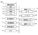
- the driving support system 100 includes a driving support ECU 1, a notification device 2, a front monitoring sensor 3, a narrow area communication unit 4, a vehicle state sensor 5, and a locator 6.
- the notification device 2 here is a device that notifies predetermined information to an occupant (hereinafter referred to as a driver) seated in a driver's seat using sound, light, vibration, or the like.
- the driving support system 100 of the present embodiment is assumed to include a speaker 2A, a display 2B, a peripheral vision device 2C, and a tactile device 2D as the notification device 2.
- ECU in the member name is an abbreviation for Electronic Control Unit, and means an electronic control device.
- Each of the various notification devices 2, the forward monitoring sensor 3, the narrow area communication unit 4, the vehicle state sensor 5, and the locator 6 is connected via a communication network (hereinafter referred to as LAN: Local Area Network) built in the vehicle.
- the driving support ECU 1 is communicably connected.
- the vehicle on which the driving support system 100 is mounted is also referred to as own vehicle Hv.
- the driving assistance ECU 1 sequentially determines the risk of a collision with the preceding vehicle Pv, and determines that the possibility of a collision with the preceding vehicle Pv is equal to or higher than a predetermined level, the driver assists the driver in cooperation with the notification device 2.
- This is an ECU that performs a process of notifying the danger of a collision with the preceding vehicle Pv (hereinafter, a notification process).
- the driving support ECU 1 corresponds to a driving support device.
- the driving support ECU 1 is configured as a computer. That is, the driving assistance ECU 1 includes a CPU 11 that executes various arithmetic processes, a flash memory 12 that is a nonvolatile memory, a RAM 13 that is a volatile memory, an I / O 14, and a bus line that connects these configurations. .
- the CPU 11 may be realized using, for example, a microprocessor.
- the I / O 14 is an interface for the driving support ECU 1 to input / output data with an external device (for example, the front monitoring sensor 3).
- the I / O 14 may be realized using an IC, a digital circuit element, an analog circuit element, or the like.
- the flash memory 12 stores a program for causing a normal computer to function as the driving assistance ECU 1 (hereinafter, driving assistance program).
- driving assistance program may be stored in a non-transitory tangible storage medium (non- transitory tangible storage medium) including the flash memory 12.
- Executing the driving support program by the CPU 11 corresponds to executing a method corresponding to the driving support program.
- the driving support ECU 1 provides various functions when the CPU 11 executes the driving support program. Various functions of the driving support ECU 1 will be described later.
- Speaker 2A outputs sound and alarm sound based on the signal input from driving support ECU1.
- the speaker 2A may be a parametric speaker that realizes a sharp directivity by using ultrasonic waves.
- the display 2B is a device that displays an image input from the driving support ECU 1.
- the display 2B is a display (so-called center display) provided at the uppermost portion of the instrument panel in the vehicle width direction center (hereinafter referred to as the center region).
- the display 2B is capable of full color display and can be realized using a liquid crystal display, an organic EL display, a plasma display, or the like.
- the display 2B may be a head-up display that projects a virtual image on a part of the windshield in front of the driver's seat.
- the display 2B may be a display (so-called meter display) arranged in a region located in front of the driver's seat on the instrument panel.
- the display 2B may be a display mounted at a position other than the position described above, or a display included in an information processing terminal brought into the vehicle interior by a driver.
- Peripheral vision device 2C is a light emitting device realized using LEDs or the like.
- the peripheral vision device 2C is disposed at a position that enters the peripheral visual field of the driver whose line of sight is directed in the front direction of the host vehicle Hv.
- the peripheral visual field here refers to a region that is out of the effective visual field and enters the field of view.
- the effective visual field may be assumed to be a range in which, for example, the vertical direction is within 30 degrees and the horizontal direction is within 20 degrees with reference to the direction in which the line of sight is directed.
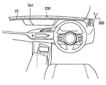
- the part that enters the peripheral vision of the driver whose line of sight is directed in the front direction of the host vehicle Hv in the passenger compartment is, for example, the upper surface portion (hereinafter, instrument panel upper surface portion) 200 of the instrument panel or the vehicle interior side of the front pillar.
- the surface portion 300 is, for example, the upper surface portion (hereinafter, instrument panel upper surface portion) 200 of the instrument panel or the vehicle interior side of the front pillar.
- the peripheral vision device 2C is realized by arranging a plurality of light emitting elements along the vehicle width direction on the instrument panel upper surface portion 200 as shown in FIG.
- the plurality of light emitting elements constituting the peripheral vision device 2 ⁇ / b> C may be disposed along a portion where the lower end portion of the windshield and the instrument panel upper surface portion 200 are connected to each other, or at the edge on the seat side in the instrument panel upper surface portion 200. It may be arranged along.
- the peripheral vision device 2 ⁇ / b> C causes some or all of the plurality of light emitting elements to emit light based on an instruction from the driving support ECU 1.
- the peripheral vision device 2C forms a partial attraction spot Spt by causing the light emitting element at a position corresponding to the instruction content from the driving support ECU 1 to emit light in a predetermined light emission mode.
- Elements constituting the light emission mode include color, luminance, blinking presence / absence, blinking interval, and the like. Since the attracting spot Spt itself provided by the peripheral vision device 2C is realized by causing a part of the plurality of light emitting elements to emit light locally, the position of the attracting spot Spt can be moved in the width direction. In addition, the peripheral vision device 2C can change the emission color and emission size of the attracting spot Spt.
- the tactile device 2D is a device that stimulates the tactile sensation of the driver by generating vibration or the like.
- a vibrator disposed on a portion that comes into contact with the driver's body, such as a steering wheel, an accelerator pedal, a brake pedal, a driver's seat, or a seat belt, can be employed.
- the haptic device 2D is a vibrator arranged on an accelerator pedal.
- the tactile device 2D generates a vibration in the instructed vibration mode based on an instruction from the driving support ECU 1.
- the vibration mode here includes the intensity of vibration, the generation interval of vibration, and the like.
- the tactile device 2D is not limited to vibration, and may be a device that applies a pressing force to a driver's hand or an illusion of traction force using a mechanism that performs asymmetric vibration, for example.
- the tactile sense here also includes warm sense. That is, the tactile device 2D may stimulate the driver's tactile sense using heat.
- the medium for transferring heat may be a steering wheel or the like, or air blown from an air conditioner.
- the front monitoring sensor 3 is a device that collects information about other vehicles in front of the host vehicle Hv and the traveling environment.
- a forward monitoring camera that images a predetermined range in front of the vehicle
- a millimeter wave radar that transmits an exploration wave to the predetermined range in front of the vehicle
- LIDAR Light Detection and Ranging / Laser Imaging Detection and Ranging
- Sonar etc.
- the driving support system 100 includes, as the forward monitoring sensor 3, a forward monitoring camera that is mounted so as to image the front of the vehicle, and a millimeter wave radar (hereinafter referred to as a forward radar) that uses the front of the vehicle as a detection area. Shall.
- the front monitoring camera as the front monitoring sensor 3 sequentially outputs captured images to the driving assistance ECU 1.
- the forward radar as the forward monitoring sensor 3 detects another vehicle (that is, the preceding vehicle Pv) traveling in front of the host vehicle Hv by transmitting and receiving an exploration wave, and when detecting the preceding vehicle Pv, The inter-vehicle distance and relative speed Vr between the preceding vehicle Pv and the host vehicle Hv are sequentially detected.
- Leading vehicles include motorbikes, motorcycles, and bicycles. Data indicating the inter-vehicle distance from the preceding vehicle Pv and the relative speed Vr are sequentially provided to the driving support ECU 1 as detection result data.
- the relative speed Vr may represent a relative speed of the preceding vehicle Pv with respect to the host vehicle Hv.
- the narrow area communication unit 4 is a communication module for performing direct (in other words, not via a wide area communication network) wireless communication with other vehicles existing around the vehicle Hv using radio waves in a predetermined frequency band. is there. That is, the narrow area communication part 4 is a communication module for implementing vehicle-to-vehicle communication.
- the frequency band used for vehicle-to-vehicle communication is, for example, the 760 MHz band.
- a 2.4 GHz band, a 5.9 GHz band, or the like can be used.
- Any communication standard for realizing vehicle-to-vehicle communication can be adopted.
- the standard of WAVE (Wireless Access in Vehicular Environment) disclosed in IEEE1609 or the like can be adopted.
- the narrow area communication unit 4 When receiving the vehicle information packet transmitted from the other vehicle, the narrow area communication unit 4 provides the data shown in the vehicle information packet to the driving support ECU 1.
- the vehicle information packet here is a communication packet indicating the vehicle information of the vehicle (that is, the transmission source vehicle) that has transmitted the vehicle information packet.
- the vehicle information includes the current position, traveling direction, traveling speed, acceleration, and the like of the transmission source vehicle.
- the vehicle information packet includes information such as the transmission time of the communication packet and transmission source information.
- the transmission source information is an identification number (so-called vehicle ID) assigned to the vehicle corresponding to the transmission source. That is, the narrow area communication unit 4 sequentially provides the driving support ECU 1 with vehicle information (hereinafter, other vehicle information) of the other vehicle indicated in the vehicle information packet transmitted from the other vehicle as needed.
- the driving support ECU 1 is configured to acquire the vehicle information of the other vehicle by communication not via the wide area communication network, but is not limited thereto.
- the driving assistance ECU 1 may be configured to acquire vehicle information of other vehicles via a wide area communication network.
- the vehicle state sensor 5 is a sensor that detects a state quantity related to traveling control of the host vehicle Hv.
- Examples of the vehicle state sensor 5 include a vehicle speed sensor, an acceleration sensor, a shift position sensor, a rudder angle sensor, an accelerator sensor, and a brake sensor.
- the vehicle speed sensor is a sensor that detects the traveling speed Vh of the host vehicle Hv
- the acceleration sensor is a sensor that detects acceleration acting in the vehicle longitudinal direction and acceleration acting in the vehicle width direction.
- the shift position sensor is a sensor that detects the position of the shift lever.
- the steering angle sensor is a sensor that detects the rotation angle (so-called steering angle) of the steering wheel, and functions as a sensor that detects the steering amount of the driver.
- the brake sensor is a sensor that detects the position of the brake pedal, in other words, the amount by which the brake pedal is depressed by the driver (hereinafter referred to as brake depression amount).
- the accelerator sensor is a sensor that detects the position of the accelerator pedal, in other words, the amount by which the accelerator pedal is depressed by the driver (hereinafter referred to as accelerator depression amount).
- Each sensor sequentially provides the driving support ECU 1 with data indicating the current value (that is, the detection result) of the physical state quantity to be detected.
- the type of sensor that the driving support system 100 should have as the vehicle state sensor 5 may be designed as appropriate, and need not include all the sensors described above.
- Locator 6 is a device that measures the current position of the vehicle.
- the locator 6 is realized using, for example, a GNSS receiver, an inertial sensor, and a map database (hereinafter referred to as DB).
- the GNSS receiver is a device that sequentially detects the current position of the GNSS receiver (for example, every 100 milliseconds) by receiving navigation signals transmitted from positioning satellites that constitute a GNSS (Global Navigation Satellite System). is there.
- the inertial sensor is, for example, a three-axis gyro sensor or a three-axis acceleration sensor.
- the map DB is a non-volatile memory that stores map data indicating road connection relationships and the like.
- the locator 6 sequentially identifies the current position of the host vehicle Hv by combining the positioning result of the GNSS receiver, the measurement result of the inertial sensor, and the map data. Then, vehicle position data indicating the specified current position is sequentially provided to the driving assistance ECU 1.
- the current position of the host vehicle Hv may be expressed by, for example, latitude, longitude, and altitude.
- the locator 6 reads map data in a predetermined range determined based on the current position from the map DB, and provides it to the driving support ECU 1.
- the map data may be obtained from an external server or the like via a wide area communication network.
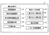
- the driving support ECU 1 provides functions corresponding to the various functional blocks shown in FIG. 3 when the CPU 11 executes the driving support program described above. That is, the driving assistance ECU 1 includes, as functional blocks, an environment recognition unit F1, a vehicle state recognition unit F2, a safe inter-vehicle distance calculation unit F3, an approach degree calculation unit F4, a TTC calculation unit F5, a notification level determination unit F6, and a notification processing unit F7. Is provided.
- the functional blocks provided in the driving support ECU 1 may be realized as hardware using a logic circuit or the like.
- the aspect realized as hardware includes an aspect realized using one or a plurality of ICs. Further, part or all of the functional blocks provided in the driving support ECU 1 may be realized by a combination of software execution by the CPU 11 and hardware members.
- the environment recognition unit F1 is configured to sequentially acquire information on the behavior of the preceding vehicle Pv, the weather, the road surface condition, and the external environment of external brightness. Specifically, the environment recognition unit F1 specifies the inter-vehicle distance from the preceding vehicle Pv, the relative speed Vr, and the traveling speed Vp based on the detection result of the forward monitoring sensor 3. The environment recognition unit F1 corresponds to an inter-vehicle distance acquisition unit.
- the traveling speed Vp of the preceding vehicle Pv may be calculated from the traveling speed Vh of the host vehicle Hv and the relative speed Vr of the preceding vehicle Pv with respect to the host vehicle Hv.
- the traveling speed Vp of the preceding vehicle Pv is specified by referring to the vehicle information packet transmitted from the preceding vehicle Pv among the vehicle information packets received by the narrow area communication unit 4. Also good.
- the association between the other vehicle that is performing the inter-vehicle communication and the preceding vehicle Pv may be performed by a known method such as a method that uses a temporal change in the relative position with respect to the host vehicle Hv.
- the environment recognition unit F1 stores data indicating the inter-vehicle distance from the preceding vehicle Pv, the relative speed Vr of the host vehicle Hv with respect to the preceding vehicle Pv, and the traveling speed Vp of the preceding vehicle Pv in the RAM 13 or the like as preceding vehicle data.
- the environment recognition unit F1 acquires the detection result of the front monitoring sensor 3 at a predetermined time interval (for example, every 100 milliseconds), generates and stores the preceding vehicle data.
- the plurality of preceding vehicle data having different generation points may be sorted and stored in the RAM 13 in chronological order so that the latest preceding vehicle data is at the head, for example.
- the preceding vehicle data that has been stored for a certain period of time may be sequentially discarded.
- the environment recognition unit F1 analyzes the captured image of the front monitoring camera as the front monitoring sensor 3, and thus the road surface state such as whether the road surface is wet, snowy, or a paved road is also detected. Identify.
- the road surface condition derived from the weather such as whether the road surface is wet may be estimated from the detection result of the rain sensor, or may be estimated from the operating state of the wiper.
- the weather information may be estimated from the detection result of the above-described rain sensor and the operating state of the wiper.
- the weather information may be acquired by receiving the weather information distributed from the center.
- the external brightness can be specified from a detection result of an illuminance sensor (not shown) or a captured image of the front monitoring camera.
- the environment recognition unit F1 of the present embodiment acquires vehicle position data indicating the current position of the host vehicle Hv and map data around the host vehicle Hv from the locator 6. Moreover, the other vehicle information provided from the narrow area communication part 4 is acquired, and it distinguishes for every vehicle and preserve
- the vehicle state recognition unit F2 sequentially identifies the state of the host vehicle Hv based on the signal input from the vehicle state sensor 5. For example, the vehicle state recognition unit F2 sequentially specifies the traveling speed Vh of the host vehicle Hv, the steering angle, the accelerator stepping amount, the brake stepping amount, the operating state of the direction indicator, the acceleration acting on the host vehicle Hv, and the like. . Data indicating the traveling speed Vh and the like of the host vehicle Hv is stored in the RAM 13 and the like as host vehicle data. The plurality of host vehicle data having different generation points may be sorted and stored in the RAM 13 in chronological order so that the latest host vehicle data comes first. The own vehicle data that has been stored for a certain period of time may be sequentially discarded.
- the safe inter-vehicle distance calculation unit F3 is configured to calculate a predetermined safe inter-vehicle distance Ls corresponding to the current traveling speed of the host vehicle Hv.
- the safe inter-vehicle distance Ls is a parameter that represents the inter-vehicle distance from the appropriate preceding vehicle Pv corresponding to the traveling speed Vh of the host vehicle Hv.
- the safe inter-vehicle distance Ls for each traveling speed Vh is appropriately designed by a designer or the like. As illustrated in FIG. 4, the safe inter-vehicle distance Ls is designed to increase as the traveling speed Vh of the host vehicle Hv increases. Data indicating the correspondence between the traveling speed and the safe inter-vehicle distance Ls may be designed in advance and stored in the flash memory 12.
- FIG. 4 illustrates a mode in which the safe inter-vehicle distance Ls increases in a curve according to the traveling speed
- the safe inter-vehicle distance Ls may be set to increase linearly or stepwise as the traveling speed Vh increases.
- the safe inter-vehicle distance Ls may be set so as to be set to a larger value as the brightness outside the vehicle compartment and other driving environments such as weather deteriorate. That is, the safe inter-vehicle distance Ls may be set to be determined from other travel environments such as time zone (for example, day / night) and weather, in addition to the travel speed Vh of the host vehicle Hv.
- the safe inter-vehicle distance Ls is a parameter that is determined without depending on the traveling speed Vp of the preceding vehicle Pv (in other words, not used).
- the parameter determined without depending on the traveling speed Vp of the preceding vehicle Pv corresponds to a parameter determined without depending on the relative speed Vr of the host vehicle Hv with respect to the preceding vehicle Pv.
- the approach degree calculation unit F4 divides the safe inter-vehicle distance Ls by the actual inter-vehicle distance (hereinafter, actual inter-vehicle distance) L with the preceding vehicle Pv acquired by the environment recognition unit F1.
- the approach degree D is calculated.
- the approach degree D is a parameter indicating whether or not the inter-vehicle distance between the preceding vehicle Pv and the host vehicle Hv is sufficiently secured.
- the state where the inter-vehicle distance between the preceding vehicle Pv and the host vehicle Hv is insufficient corresponds to a state where the risk of the host vehicle Hv colliding with the preceding vehicle Pv is relatively high. Therefore, the approach degree D functions as a parameter representing the degree of danger that the host vehicle Hv will collide with the preceding vehicle Pv.
- the degree of approach D becomes larger as the actual inter-vehicle distance L is shorter than the safe inter-vehicle distance Ls. That is, the higher the degree of approach D, the higher the degree of risk that the host vehicle Hv will collide with the preceding vehicle Pv. Note that when the actual inter-vehicle distance L coincides with the safe inter-vehicle distance Ls, the approach degree D is 1.
- the approach degree D calculated by the approach degree calculation unit F4 is sequentially provided to the notification level determination unit F6.
- the approach degree calculation unit F4 corresponds to a first index value calculation part, and the approach degree D corresponds to a first risk index value.
- the TTC calculation unit F5 determines that the host vehicle Hv is the preceding vehicle Pv.
- a collision margin time (hereinafter referred to as TTC: Time-To-Collision), which is the remaining time until a collision, is sequentially calculated.
- TTC Time-To-Collision
- a well-known algorithm can be used as the TTC calculation algorithm.
- the actual inter-vehicle distance L may be a value obtained by dividing the actual vehicle distance L by the relative speed Vr of the host vehicle Hv with respect to the preceding vehicle Pv.
- the calculation result of the TTC calculation unit F5 is sequentially provided to the notification level determination unit F6.
- the TTC is a positive value
- the larger the value the smaller the degree of risk that the host vehicle Hv will collide with the preceding vehicle Pv.
- the calculation of the TTC itself may be stopped, or the maximum value that can be set on the program as the TTC (hereinafter referred to as the TTC).
- MAX value may be set.
- the case where the relative speed Vr is a negative value corresponds to the case where the preceding vehicle Pv and the host vehicle Hv are separated from each other.
- the MAX value is set in the TTC.
- the MAX value functions as a value representing infinity for convenience.
- the relative speed Vr is 0, the MAX value is set in the TTC.
- the TTC calculation unit F5 corresponds to a second index value calculation unit, and TTC corresponds to a second risk index value.
- the notification level determination unit F6 indicates the strength of appealing the driver to the risk of a collision with the preceding vehicle Pv based on the proximity D calculated by the proximity calculation unit F4 and the TTC calculated by the TTC calculation unit F5. It is the structure which determines an alerting
- the notification level determination unit F6 includes a first risk level calculation unit F61 and a second risk level calculation unit F62 as finer components (in other words, sub-functions) for determining the notification level.
- the first risk level calculation unit F61 uses factors other than the traveling speed Vp of the preceding vehicle Pv, such as the traveling speed Vh of the host vehicle Hv and the road surface state, based on the approach degree D calculated by the approach degree calculation unit F4. A first risk level is calculated.
- the first risk level calculation unit F61 determines the first risk level in four stages from 1 to 4.
- Level 1 corresponds to a state where the first risk level is the lowest and there is almost no risk of collision with the preceding vehicle Pv (in other words, it is sufficiently small).
- Level 4 is a state where the first risk level is the highest, and corresponds to a state where the driver should be alerted.
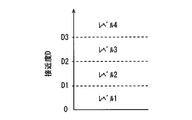
- the first risk level calculation unit F61 determines that the first risk level is higher as the value of the approach degree D is larger as shown in FIG. Specifically, when the approach degree D is less than the predetermined threshold value D1, it is determined as level 1, and when the approach degree D is equal to or greater than the threshold value D1 and less than the threshold value D2, it is determined as level 2. Further, when the degree of approach D is greater than or equal to the threshold D2 and less than the threshold D3, it is determined as level 3. Then, when the approach degree D is equal to or greater than the threshold value D3, it is determined as level 4.
- the threshold value D1 may be designed as appropriate, and is 1.0 here.
- the threshold value D2 may be appropriately designed in a range larger than the threshold value D1, and is set to 1.5 as an example here.
- the threshold value D3 may be appropriately designed in a range larger than the threshold value D2, and is set to 2.0 as an example here.
- the second risk level calculation unit F62 calculates a second risk level based on the relative speed Vr of the host vehicle Hv with respect to the preceding vehicle Pv based on the TTC calculated by the TTC calculation unit F5.
- the second risk level calculation unit F62 determines the second risk level in three stages of levels 1 to 3.
- Level 1 is the state with the lowest second risk level.
- Level 1 corresponds to a state where there is almost no risk of collision with the preceding vehicle Pv (in other words, sufficiently small) if the current relative speed Vr is maintained.
- Level 3 is a state where the second risk level is the highest, and corresponds to a state where the driver should be alerted.
- the second risk level calculation unit F62 determines that the second risk level is higher as the TTC value is smaller as shown in FIG. Specifically, when TTC is equal to or greater than a predetermined threshold T1, it is determined as level 1, and when TTC is less than threshold T1 and equal to or greater than threshold T2, it is determined as level 2. Further, when TTC is less than the threshold value T2, it is determined as level 3.
- the specific value of the threshold value T1 may be appropriately set based on various tests, and is 14 seconds here.
- the configuration in which the threshold T1 is set to 14 seconds is a configuration in consideration of the property that the driver perceives the approach to the preceding vehicle Pv by the increase rate of the visual size of the preceding vehicle Pv.
- TTC is 14 seconds or more
- TTC is 14 seconds or more
- the region where TTC is 14 seconds or more corresponds to a region where it is difficult for the driver to understand the meaning of the alarm even if an alarm is output, and the driver may be bothered.
- the threshold value T2 may be appropriately designed in a range smaller than the threshold value T1, and is set to 5 seconds as an example here.
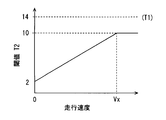
- the threshold value T2 may be dynamically determined according to the traveling speed Vh of the host vehicle Hv. For example, as shown in FIG. 7, the threshold value T ⁇ b> 2 may be set to increase as the traveling speed increases. However, it is assumed that an upper limit value is set for the threshold T2 so that the threshold T2 does not exceed the threshold T1.
- the upper limit value of the threshold value T2 may be appropriately designed in a range smaller than the threshold value T1.
- FIG. 7 shows an aspect in which the upper limit value of the threshold value T2 is set to 10 seconds.
- Vx in FIG. 7 indicates the traveling speed when the threshold value T2 reaches the upper limit value. Vx may be set to 100 km / h, for example.
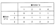
- the notification level determination unit F6 determines the notification level based on the first risk level calculated by the first risk level calculation unit F61 and the second risk level calculated by the second risk level calculation unit F62 as described above. Determine sequentially.
- the notification level determination unit F6 determines the notification level in four stages (that is, a plurality of stages) of levels 0 to 3 so as to include a level where the notification process is not performed.
- Level 0 is a level at which notification processing is not performed.
- Level 1 is a level for notifying the driver that the distance between the preceding vehicle Pv and the inter-vehicle distance is slightly short.
- Level 2 is a level that appeals to the driver more strongly than Level 1 to pay attention to a collision with the preceding vehicle Pv.
- Level 2 is a level for the purpose of prompting the driver to turn his gaze forward even if the driver is looking aside or in a low arousal state.
- Level 3 is a level that appeals to the driver more strongly than Level 2 to pay attention to a collision with the preceding vehicle Pv.
- Level 3 is a level for the purpose of reliably telling the driver of the danger of a collision with the preceding vehicle Pv. Details of the notification mode at each notification level will be described later.
- the notification level determination unit F6 determines the notification level using data indicating a correspondence relationship between the first risk level, the second risk level, and the notification level, for example, as shown in FIG. As illustrated in FIG. 8, the notification level determination unit F6 determines that the notification level is higher as the first risk level is higher and as the second risk level is higher. The operation of the notification level determination unit F6 will be described later separately.
- the notification processing unit F7 is configured to perform processing (that is, notification processing) for notifying the driver of the danger of a collision with the preceding vehicle Pv in a notification mode according to the notification level determined by the notification level determination unit F6. .
- the notification processing unit F7 displays an image (hereinafter referred to as a caution image) that calls attention to the inter-vehicle distance from the preceding vehicle Pv on the display 2B, and sets the peripheral vision device 2C to a predetermined value. Light up gradually until the target brightness is reached. At this time, the final luminance of the peripheral vision device 2C is set to a luminance that does not bother the driver. That is, when the notification level is 1, the notification processing unit F7 dimly lights the peripheral vision device 2C.
- the emission color may be a yellowish green, yellow, orange, or the like that weakens the driver's attention.
- the notification processing unit F7 outputs an alarm sound from the speaker 2A while displaying a caution image on the display 2B.
- the alarm sound that is output when the notification level is 2 is set to a relatively lower sound than the alarm sound that is output when the notification level described later is 3.
- the length of the sound and the repetition interval are also set to relatively long values.
- the sound pressure is also set to a relatively small value.
- the notification processing unit F7 causes the peripheral vision device 2C to blink at a relatively long interval (in other words, slowly).
- the emission color may be the same as when the notification level is 1, or a reddish hue than when the notification level is 1.
- the notification processing unit F7 vibrates the tactile device 2D with a relatively weak vibration pattern.
- the notification processing unit F7 displays a predetermined warning image on the display 2B.
- the warning image is an image that strongly calls attention (that is, warns) about the inter-vehicle distance from the preceding vehicle Pv, and is an image that can be expected to give the driver a sense of crisis more than the warning image. For example, when the background color of the caution image is yellow, an image in which the background color of the warning image is red may be used.
- the notification processing unit F7 outputs an alarm sound from the speaker 2A. Note that the alarm sound to be output when the notification level is 3 is set to a relatively higher sound than the alarm sound output when the notification level is 2.
- the length of the sound and the repetition interval are also set to relatively short values.
- the sound pressure is also set to a relatively strong value.
- the notification processing unit F7 blinks the peripheral vision device 2C at relatively short intervals (in other words, quickly).
- the emission color may be a reddish hue (for example, red) than when the notification level is 2.
- the notification processing unit F7 vibrates the tactile device 2D with a relatively strong vibration pattern.
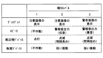
- FIG. 9 is a diagram summarizing the operation mode (in other words, the notification mode) of each notification device for each notification level described above.
- the notification mode for each notification level shown in FIG. 9 is an example, and can be changed as appropriate.
- the higher the notification level the shorter the inter-vehicle distance from the preceding vehicle Pv, in other words, the mode of appealing to the driver that the risk of collision has increased.
- To appeal the predetermined information to the driver strongly corresponds to strengthening visual, tactile and auditory stimuli given to the driver.
- the notification related process is a process for starting a notification process in a mode corresponding to the notification level or canceling (in other words, stopping) the notification process in the matter.
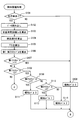
- the flowcharts shown in FIGS. 10 and 11 may be executed sequentially (for example, every 100 milliseconds) while the traveling power source (for example, the ignition power source) of the host vehicle Hv is on.
- step S101 the notification level determination unit F6 determines whether or not a preceding vehicle Pv exists. Whether or not the preceding vehicle Pv exists is determined based on the detection result of the front monitoring sensor 3. If the preceding vehicle Pv exists, an affirmative determination is made in step S101 and the process proceeds to step S102. On the other hand, when the preceding vehicle Pv does not exist, a negative determination is made in step S101, and the process proceeds to step S108.
- step S102 data necessary for calculating the degree of approach D and TTC, such as the traveling speed Vh of the host vehicle Hv, the actual inter-vehicle distance L, and the relative speed Vr of the host vehicle Hv with respect to the preceding vehicle Pv, are read from the RAM 13 and step S102.
- the process moves to S103.
- step S103 the safe inter-vehicle distance calculation unit F3 calculates the safe inter-vehicle distance Ls corresponding to the traveling speed Vh of the host vehicle Hv, and proceeds to step S104.
- step S104 the approach degree calculation unit F4 calculates the approach degree D by dividing the safe inter-vehicle distance Ls calculated in step S103 by the actual inter-vehicle distance L, and proceeds to step S105.
- step S105 the TTC calculation unit F5 calculates TTC by dividing the actual inter-vehicle distance L by the relative speed Vr of the host vehicle Hv with respect to the preceding vehicle Pv, and proceeds to step S106.
- step S106 the first risk level calculation unit F61 calculates the current first risk level based on the approach degree D calculated in step S104. Further, the second risk level calculation unit F62 calculates the current second risk level based on the TTC calculated in step S105. When these arithmetic processes are completed, the process proceeds to step S107.
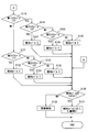
- step S107 the notification level determination unit F6 determines whether or not the current first risk level is 1. If the first risk level is 1, an affirmative determination is made in step S107 and the process proceeds to step S108. On the other hand, when the first risk level is not 1, a negative determination is made in step S107, and the process proceeds to step S109. In step S108, the notification level determination unit F6 sets the notification level to 0, and proceeds to step S126.
- step S109 the notification level determination unit F6 determines whether or not the current first risk level is 2. If the first risk level is 2, an affirmative determination is made in step S109 and the process proceeds to step S110. On the other hand, when the first risk level is not 2, a negative determination is made in step S109, and the process proceeds to step S115.
- step S110 the notification level determination unit F6 determines whether or not the current second risk level is 1. If the second risk level is 1, an affirmative determination is made in step S110 and the process proceeds to step S111. On the other hand, when the second risk level is not 1, a negative determination is made in step S110, and the process proceeds to step S112. In step S111, the notification level determination unit F6 sets the notification level to 0, and proceeds to step S126.
- step S112 the notification level determination unit F6 determines whether or not the current second risk level is 2. If the second risk level is 2, an affirmative decision is made in step S112 and the process proceeds to step S113. On the other hand, if the second risk level is not 2, that is, if the second risk level is 3, a negative determination is made in step S112 and the process proceeds to step S114. In step S113, the notification level determination unit F6 sets the notification level to 1, and proceeds to step S126. In step S114, the notification level determination unit F6 sets the notification level to 2, and proceeds to step S126.
- step S115 the notification level determination unit F6 determines whether or not the current first risk level is 3. If the first risk level is 3, an affirmative determination is made in step S115 and the process proceeds to step S116. On the other hand, if the first risk level is not 3, that is, if the first risk level is 4, a negative determination is made in step S115 and the process proceeds to step S121.
- step S116 the notification level determination unit F6 determines whether or not the current second risk level is 1. If the second risk level is 1, an affirmative determination is made in step S116 and the process proceeds to step S117. On the other hand, when the second risk level is not 1, a negative determination is made in step S116, and the process proceeds to step S118. In step S117, the notification level determination unit F6 sets the notification level to 1, and proceeds to step S126.
- step S118 the notification level determination unit F6 determines whether or not the current second risk level is 2. If the second risk level is 2, an affirmative determination is made in step S118 and the process proceeds to step S119. On the other hand, if the second risk level is not 2, that is, if the second risk level is 3, a negative determination is made in step S119 and the process proceeds to step S120. In step S119, the notification level determination unit F6 sets the notification level to 1, and proceeds to step S126. In step S120, the notification level determination unit F6 sets the notification level to 2, and proceeds to step S126.
- step S121 the notification level determination unit F6 determines whether or not the current second risk level is 1. If the second risk level is 1, an affirmative determination is made in step S121 and the process proceeds to step S122. On the other hand, when the second risk level is not 1, a negative determination is made in step S121, and the process proceeds to step S123. In step S122, the notification level determination unit F6 sets the notification level to 1, and proceeds to step S126.
- step S123 the notification level determination unit F6 determines whether or not the current second risk level is 2. If the second risk level is 2, an affirmative determination is made in step S123 and the process proceeds to step S124. On the other hand, when the second risk level is not 2, that is, when the second risk level is 3, a negative determination is made in step S123, and the process proceeds to step S125. In step S124, the notification level determination unit F6 sets the notification level to 2, and proceeds to step S126. In step S125, the notification level determination unit F6 sets the notification level to 3, and proceeds to step S126.
- step S126 the notification processing unit F7 determines whether or not the notification level determined by the above processing is 1 or more. If the notification level is 1 or higher, an affirmative determination is made in step S126 and the process proceeds to step S127. On the other hand, when the notification level is 0, a negative determination is made in step S126, and the process proceeds to step S128.
- the case where the notification level is 1 or more corresponds to the case where the notification process needs to be performed, and the case where the notification level is 0 corresponds to the case where the notification process does not need to be performed. That is, the process of step S126 corresponds to a process of determining whether or not the notification process needs to be started / continued.
- step S127 the notification processing unit F7 performs notification processing in a notification mode according to the current notification level. For example, when the notification process has already been performed at the start of this flow and the notification level determined in the previous notification-related process is different from the notification level determined in the current notification-related process The notification mode is changed to the notification level determined this time. In addition, when the notification process is not performed at the start of this flow and the notification level determined by the current notification-related processing is 1 or more, in a mode according to the notification level determined this time The notification process is started.
- the notification level already determined at the start of this flow and the notification level determined in the previous notification-related processing is the same as the notification level determined in the previous notification-related processing. In such a case, the notification process in the mode performed before the start of this flow may be continued.
- step S1208 the notification processing unit F7 stops the notification process. If the notification process is not performed at the start of this flow, the state where the notification process is not executed may be continued.
- the notification level that determines the mode of the notification process is determined by two parameters, the first risk level and the second risk level.
- the first risk level is determined according to the approach degree D calculated without using the traveling speed Vp of the preceding vehicle Pv. Therefore, the first risk level is a parameter calculated without using the traveling speed Vp of the preceding vehicle Pv.
- the second risk level is determined according to the TTC. Since the TTC is calculated based on the relative speed Vr of the host vehicle Hv with respect to the preceding vehicle Pv, the second risk level uses the relative speed Vr of the host vehicle Hv with respect to the preceding vehicle Pv, that is, the traveling speed Vp of the preceding vehicle Pv.
- This parameter is calculated by That is, according to the configuration of the present embodiment, the notification level is calculated using the first risk level calculated without using the traveling speed Vp of the preceding vehicle Pv and the traveling speed Vp of the preceding vehicle Pv. Determined using both risk levels.
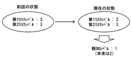
- the relative speed Vr of the host vehicle Hv with respect to the preceding vehicle Pv decreases. Since the second risk level is a parameter determined according to the relative speed Vr, when the driver performs a deceleration operation, the second risk level also decreases in response to the deceleration operation.
- the notification level is also determined by the second risk level, if the second risk level decreases, the notification level can also decrease.
- the notification mode of the notification process is changed to a relatively weak mode, or the notification process itself is stopped. Therefore, even in a situation where the inter-vehicle distance has not changed so much, the notification mode can change based on the driver's deceleration operation, so that the notification in the same notification mode continues to be implemented, which causes trouble for the driver. Fear can be reduced.
- the second risk level increases as the relative speed Vr increases even when the inter-vehicle distance has not yet changed significantly, and the notification level can increase.
- the notification mode of the notification process also changes to a relatively strong notification mode. Therefore, according to the above configuration, it is possible to reduce the possibility that the driver will notice that sudden braking of the preceding vehicle Pv is delayed. That is, according to the said structure, a risk can be alert
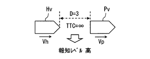
- a configuration for determining a notification level based only on TTC (hereinafter, a first assumed configuration) is also assumed.
- the TTC becomes a relatively large value when the relative speed Vr is sufficiently small. If the actual inter-vehicle distance L is short even if TTC is large, the driver has a short time margin for performing an operation for avoiding a collision with the preceding vehicle Pv when the preceding vehicle Pv suddenly brakes at the next moment. It can be said that the risk of collision is potentially high. That is, in the first assumed configuration, the notification process cannot be performed in a manner that takes into account the potential danger of a collision.
- the present embodiment not only the TTC but also the approach degree D is taken into consideration to determine the notification level.
- a notification level that reveals a potential danger that may exist even when TTC is large is determined. Therefore, as shown in FIG. 13, when the actual inter-vehicle distance L is very small, a relatively high notification level is set. As a result, the risk of collision with the preceding vehicle Pv can be more strongly appealed to the driver.
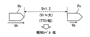
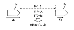
- a configuration (hereinafter referred to as a second assumed configuration) in which the notification level is determined based only on the approach degree D as in Patent Document 1 is also assumed.
- the TTC is a relatively small value when the relative speed Vr is large. If the TTC is small, it can be said that the risk of collision is potentially high because the driver has a short time margin for performing an operation for avoiding a collision with the preceding vehicle Pv.
- the notification process may not be performed in a manner that takes into account the potential danger of a collision.
- the notification level is determined by revealing a risk that does not appear only by the degree of proximity D. Therefore, as shown in FIG. 15, even if the degree of approach D is not so high, if the TTC is relatively short, a relatively high notification level is set. As a result, the risk of a collision with the preceding vehicle Pv can be strongly appealed to the driver.
- the notification level determination unit F6 may determine the notification level in consideration of the driver's state, for example, whether or not the driver is in an aside state.
- the driving support system 100 includes a driving support ECU 1, a notification device 2, a front monitoring sensor 3, a narrow communication unit 4, a vehicle state sensor 5, a locator 6, and a driver state sensor 7. I have.
- Driver state sensor 7 is a sensor that detects the state of the driver.
- the driver state includes, for example, the driver's face direction, line-of-sight direction, eyelid opening, body direction (in other words, sitting posture), handle gripping state, and the like.
- the driver's biological information such as heart rate, blood pressure, cardiac potential, pulse wave, sweating volume, body temperature, respiratory rhythm, and respiratory depth also functions as information indicating the driver's state. Further, whether or not the driver is talking with a passenger or the like is also included in the driver state.
- a driver state sensor 7 for example, a driver camera arranged so as to image the face of the driver, a microphone, a handle grip sensor, a back pressure sensor, a seat pressure sensor, a biological information sensor, or the like is adopted.
- the driver camera is a camera installed so as to take an image of the driver's face.
- the driver camera may be realized using, for example, a near-infrared light source, a near-infrared camera, and a control unit that controls them.
- the driver camera performs a well-known image recognition process on the image captured by the near-infrared camera, so that the head position of the occupant (ie, driver) in the driver's seat, the driver's face orientation, the line-of-sight direction, and the eyelid opening The degree and the like are detected sequentially.
- the driver camera may be placed at an appropriately designed position such as the steering column cover or the part of the instrument panel facing the driver's seat so as to capture the face area of the occupant seated in the driver's seat. That's fine.
- the handle grip sensor is a pressure sensor provided on the handle, and the back pressure sensor is a pressure sensor sheet arranged to detect the distribution of pressure acting on the backrest portion of the driver's seat.
- the seat pressure sensor is a pressure sensor seat disposed on the seating surface of the driver seat, and detects the distribution of pressure acting on the seating surface of the driver seat.
- the biological information sensor is, for example, a heart rate sensor that measures a heart rate. Sensors for detecting blood pressure, cardiac potential, pulse wave, sweat volume, body temperature, respiratory rhythm, and respiratory depth are also included in the biological information sensor.
- the driving support system 100 includes at least one of the various sensors described above as the driver state sensor 7.
- the driving support system 100 includes a driver camera and a heart rate sensor as the driver state sensor 7.
- Each of the driver camera and the heart rate sensor as the driver state sensor 7 sequentially provides the driving support ECU 1 with data indicating the detection result. That is, the driver assistance ECU 1 is provided with the driver's head posture, the driver's face orientation, the line-of-sight direction, the eyelid opening degree, the heart rate, and the like.
- the driving support ECU 1 in the first modification includes a driver state recognition unit F8 in addition to various functional blocks as shown in FIG.
- the driver state recognition unit F8 is configured to sequentially specify the driver state based on the detection result of the driver state sensor 7 and the detection result of the vehicle state sensor 5.
- the driver state recognition unit F8 is realized by executing software by the CPU 11.
- the driver state recognition unit F8 may be realized as hardware using an IC or the like.
- the driver state recognition unit F8 determines, for example, whether or not the driver is looking aside without looking at the front of the vehicle, based on the driver's face orientation and line-of-sight direction specified by the driver camera. For example, when the driver's face is directed in a direction in which an angle with the vehicle front direction is 20 degrees or more, it is determined that the driver is looking aside.
- the driver is dozing from the degree of opening of the driver's heel. Further, even when the driver is not in a dozing state, it is determined whether or not the driver is in a low arousal state in which the driver's consciousness level is lowered based on a temporal change such as the degree of opening of the eyelids. In addition, it is determined whether or not the state is a random state based on the steering angle fluctuation, the gaze fluctuation, or the like.
- the method of determining the driver's state such as a side-by-side state, a dozing state, a low arousal state, and a vague state is not limited to the method described above. A well-known method can be adopted.
- the driver state recognition unit F8 determines that the driver is in an abnormal state when it is determined that the driver corresponds to any of the aside state, the dozing state, the low arousal state, and the loose state, and the driver is in an abnormal state.
- An abnormal flag Fd indicating whether or not is set to 1.
- the abnormality flag Fd is set to 0.
- the state where the abnormality flag Fd is set to 1 corresponds to the state where the abnormality flag Fd is set to ON.
- the state where the abnormality flag Fd is set to 0 corresponds to the state where the abnormality flag Fd is set to off.
- the driver state recognition unit F8 determines all the states of a look-ahead state, a dozing state, a low arousal state, and a casual state.
- the present invention is not limited to this. You may be comprised so that only a part of a look-a-side state, a dozing state, a low arousal state, and a casual state may be determined.
- the set value of the abnormality flag Fd is referred to by the notification level determination unit F6 (particularly, the first risk level calculation unit F61).
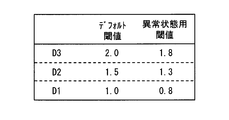
- the first risk level calculation unit F61 in Modification 1 calculates the first risk level using not only the proximity D calculated by the proximity calculation unit F4 but also the determination result of the driver state recognition unit F8. Specifically, the first risk level calculation unit F61 of the first modification includes a default threshold and an abnormal condition threshold as thresholds D1 to D3 for calculating the first risk level.
- the default threshold value is a threshold value used as the threshold values D1 to D3 when the driver state recognition unit F8 determines that the driver is not in an abnormal state (in other words, a normal state).
- the abnormal state threshold is a threshold used as the thresholds D1 to D3 when the driver state recognition unit F8 determines that the driver is in an abnormal state.
- the default threshold value may be set to the same value as in the above-described embodiment.
- the abnormal state threshold is set to a value relatively smaller than the default threshold.
- the threshold value for abnormal state is set to a value smaller by 0.2 than the default threshold value.
- the first risk level is easily determined to be high.
- the fact that the first risk level is easily determined is equivalent to the fact that the notification level is easily determined.
- the timing at which the notification processing is started and the timing at which the notification processing in a relatively strong notification mode is executed are advanced. That is, by setting the abnormal condition threshold value to a value relatively smaller than the default threshold value, the timing at which the notification process is started or the timing at which the notification process in a relatively strong notification mode is executed can be advanced. it can.
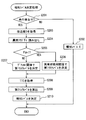
- FIG. 19 is a flowchart for explaining a process in which the notification level determination unit F6 determines the notification level (hereinafter, notification level determination process).
- the flowchart shown in FIG. 19 may be executed sequentially while the traveling power source of the host vehicle Hv is on, as in the notification-related processing of the embodiment.
- the notification level determination process illustrated in FIG. 19 corresponds to a process in which the process executed by the notification level determination unit F6 is extracted from the notification-related processes performed by the driving support ECU 1. Each step provided in the flowchart shown in FIG. 19 is executed by the notification level determination unit F6.
- step S201 it is determined whether or not a preceding vehicle Pv exists.
- a negative determination is made in step S201, and the process proceeds to step S202.
- an affirmative determination is made in step S201 and the process proceeds to step S202.
- step S202 the notification level is set to 0 and this flow ends.
- step S203 the approach degree D calculated by the approach degree calculation unit F4 is acquired, and the process proceeds to step S204.
- step S204 the set value of the abnormality flag Fd is read, and the process proceeds to step S205.
- step S205 it is determined whether or not the abnormality flag Fd is set to 1. If the abnormality flag Fd is set to 1, an affirmative determination is made in step S205 and the process proceeds to step S206. On the other hand, if the abnormality flag Fd is not set to 1, that is, if the abnormality flag Fd is set to 0, a negative determination is made in step S205 and the process proceeds to step S207.
- step S206 the first risk level calculation unit F61 calculates a first risk level corresponding to the degree of approach D acquired in step S203 using a predetermined abnormal state threshold instead of the default threshold, and then proceeds to step S208. Move.
- step S207 the first risk level corresponding to the degree of approach D acquired in step S203 is calculated using the default threshold, and the process proceeds to step S208.
- step S208 the TTC calculated by the TTC calculation unit F5 is acquired, and the process proceeds to step S209.
- step S209 the second risk level corresponding to the TTC acquired in step S208 is calculated, and the process proceeds to step S210.
- step S210 the notification level is determined based on the first risk level and the second risk level determined by the above processing, and this flow is terminated.
- the notification processing unit F7 performs the notification processing or stops the notification processing according to the determined notification level.
- ⁇ Summary of Modification 1> when the driver is in a predetermined abnormal state such as a look-aside state, a threshold value set so that the first risk level is relatively easily determined to be a high level is used. Determine the first risk level. According to such a configuration, the timing at which the notification processing is started and the timing at which the notification processing in a relatively strong notification mode is executed are advanced. As a result, it can be expected that the timing for returning the driver from the abnormal state to the normal state or for allowing the driver to confirm the front is advanced.
- a mode is disclosed in which the notification level is calculated according to the same rules as when the driver is determined to be in a normal state even when the driver is determined to be in an abnormal state.
- the notification level determination rule may be set so that the notification level is determined to be higher than when the driver is determined to be in a normal state. good.
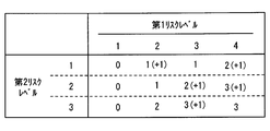
- the notification level is determined using the correspondence table shown in FIG. 8, while when the driver is determined to be in an abnormal state, it is shown in FIG. The notification level is determined using the correspondence table.
- the numbers in parentheses in FIG. 20 represent the difference from the notification level set when it is determined that the driver is in a normal state. That is, in the example shown in FIG. 20, when the first risk level is 2 and the second risk level is 1, and it is determined that the driver is in an abnormal state, the driver is in a normal state. This indicates that the notification level is determined to be one step higher than the case where it is determined that there is. If the first risk level is 4 and the second risk level is 1, or if the first risk level is 3 and the second risk level is 2, the first risk level is 4 and the second risk level is 2, The same applies when the first risk level is 3 and the second risk level is 3.
- the driver when the driver is in an abnormal state, not only the start timing of the notification process is advanced, but also the stimulus output by the notification process is strengthened. According to such an aspect, the driver can easily recognize that there is a risk of collision with the preceding vehicle. Naturally, if the driver recognizes the danger of a collision with the preceding vehicle, it can be expected that an operation for reducing the danger of the collision, such as stopping the acceleration operation or executing the deceleration operation, is performed. That is, according to the configuration of the second modification, it can be expected that the safety is further improved.
- Modification 3 In Modification 1 and Modification 2 described above, when the driver state recognition unit F8 determines that the driver is in an abnormal state, the first risk level is higher than when the driver is determined to be in a normal state.
- the thresholds D1 to D3 for determining the first risk level are changed so as to be easily determined to be high, the present invention is not limited to this.
- the threshold values T1 to T2 may be changed so that the second risk level is determined to be higher than when the driver is determined to be in a normal state.
- a default threshold value applied when the driver state is determined by the driver state recognition unit F8 to be in a normal state, and a driver being in an abnormal state An abnormal state threshold value to be applied when the determination is made may be prepared, and these may be properly used according to the determination result of the driver state recognition unit F8.
- the abnormal condition threshold for determining the second risk level may be set to a value larger than the default threshold.
- the abnormal condition threshold for determining the second risk level is a value obtained by multiplying the default threshold by a predetermined coefficient (for example, 1.2) larger than 1 or a predetermined positive number (for example, 1 second).
- the value may be set as follows. According to such a configuration, when the driver state recognition unit F8 determines that the driver is in an abnormal state, the second risk level is easily determined higher than when the driver is determined to be in a normal state. Become. As a result, when the driver is in an abnormal state, the notification level is easily determined to be higher than when the driver is in a normal state.
- the notification level determination unit F6 may determine the notification level in consideration of the state of the notification level driver in view of the state transition of the host vehicle Hv.
- the state transition of the host vehicle Hv here refers to a change in the first risk level or a change in the second risk level.
- a first modification such a configuration will be described as a first modification.
- the notification level determination unit F6 in Modification 4 stores the determined first risk level and second risk level in the RAM 13 as previous state information.
- the notification level determination unit F6 in Modification 4 stores the determined first risk level and second risk level in the RAM 13 as previous state information.
- the first and second risk levels stored in the RAM 13 as the previous state information are referred to, and the first risk level is It is determined whether it has improved and whether the second risk level has improved.
- the notification level determination unit F6 determines the notification level to be lower than the original notification level determined from the current first and second risk levels.
- the case where the first risk level is improved is a case where the first risk level calculated this time is lower than the first risk level calculated last time.
- the case where the second risk level is improved is a case where the second risk level calculated this time is lower than the first risk level calculated last time.
- the notification level is set to 0.
- the notification level is also set to 0 when the second risk level is lowered from 2 to 1.
- the original notification level is 1 when the first risk level is 3 and the second risk level is 1.
- the notification level is set to 0.
- the notification level is similarly set to 0 when the second risk level is lowered from 3 to 2.
- the original notification level when the first risk level is 2 and the second risk level is 2 is 1.
- the notification level is set to 1.
- the original notification level when the first risk level is 2 and the second risk level is 3 is 2.
- the improvement in the first risk level and the second risk level means that the positional relationship between the host vehicle Hv and the preceding vehicle Pv has shifted to a safer state due to the driver's deceleration operation or the like.
- the driver is bothered by weakening the manner of the notification processing or stopping the notification processing early. Fear can be reduced.
- setting the notification level to a level lower than the original notification level based on the improvement of the first risk level is based on the fact that the value of the approach degree D has changed to a smaller value. This corresponds to setting the level lower than the original notification level. Since the degree of approach D is a parameter that indicates a safer state as it is smaller, transition of the value of the degree of approach D to a smaller value means a transition to a safer state.
- setting the notification level to a level lower than the original notification level based on the improvement of the second risk level sets the notification level to the original level based on the fact that the TTC value has changed to a larger value. This corresponds to setting a level lower than the notification level. Since TTC is a parameter that means a safer state as it is larger, transition of the TTC value to a larger value means that the TTC has shifted to a safer state.
- the index used for calculating the second risk level (in other words, the second risk index value) is not limited to the TTC.
- the second risk level calculation unit F62 may calculate the second risk level using the reciprocal of TTC.
- the second risk level may be calculated using TTC2nd considering relative speed and relative acceleration.
- the second risk level may be calculated based on a known risk index using the traveling speed Vp of the preceding vehicle Pv, such as a margin margin (MTC: Margin-To-Collision), in addition to the risk index described above. it can.
- MTC Margin-To-Collision
- the first risk level calculation unit F61 may calculate the first risk level using a safety margin time described below as a first risk index value.
- the safety margin time is a value obtained by subtracting the reaction delay time, the reaction time, and the required inter-vehicle time from the current inter-vehicle time.
- the inter-vehicle time is a value obtained by dividing the actual inter-vehicle distance L by the traveling speed Vh of the host vehicle Hv.
- the reaction delay time is a delay time required for the driver to notice that a risk event such as sudden braking of the preceding vehicle Pv has occurred.
- the reaction delay time is preset. Note that the reaction delay time may be adjusted to a long value during a dull driving or a side-viewing driving.
- the reaction time is the time taken from when the driver notices the occurrence of the risk event until the braking operation is started, and is a parameter determined by the driver's driving skill, age, and the like.
- the reaction time is preset.
- the required inter-vehicle time is a time required from when the driver starts the braking operation until the vehicle stops, and is a parameter determined by road surface conditions, vehicle type performance, and the like.
- the required inter-vehicle time is set in advance. The necessary inter-vehicle time may be adjusted so as to increase as the traveling speed Vh increases. Even if such a safety margin time is used instead of the degree of approach D, the above-described effects can be obtained.
- each section is expressed as S101, for example.
- each section can be divided into a plurality of subsections, while a plurality of sections can be combined into one section.
- each section configured in this manner can be referred to as a device, module, or means.
Abstract
Provided is a driving assistance device which, in association with a notification device, carries out a notification process of notifying a driver of the risk of a collision with the preceding car. Said device comprises: a following distance acquisition unit (F1) which successively acquires a following distance; a first index value computation unit (F4) which, on the basis of a travel speed and the following distance, computes a first risk index value which indicates a degree of risk of a collision; a second index value computation unit (F5) which, on the basis of the relative velocity of the local vehicle with regard to the preceding vehicle, successively computes a second risk index value; a notification level determination unit (F6) which, on the basis of the first and second risk index values, successively determines a notification level which indicates how forcefully the risk of collision is to be presented; and a notification processing unit (F7) which carries out the notification process in a notification mode based on the notification level.
Description
本出願は、2017年3月24日に出願された日本特許出願番号2017-59729号に基づくもので、ここにその記載内容を援用する。
This application is based on Japanese Patent Application No. 2017-59729 filed on March 24, 2017, the contents of which are incorporated herein by reference.
本開示は、先行車両との衝突の可能性をドライバに警告する運転支援装置に関するものである。
The present disclosure relates to a driving support device that warns a driver of a possibility of a collision with a preceding vehicle.
従来、先行車両との車間距離に応じて警報音を出力することによって、先行車両との衝突の可能性をドライバに警告する運転支援装置がある。例えば特許文献1には、自車両の車速に応じて安全車間距離を算出するとともに、その算出した安全車間距離を実際の先行車両との車間距離で除算した値である危険度を逐次算出し、危険度に応じた態様の警報音を出力する運転支援装置が開示されている。具体的には危険度が1以上1.5未満である場合には第1段階の警報音を出力し、危険度が1.5以上2.0未満である場合には第2段階の警報音を出力する。そして、危険度が2.0以上である場合には第3段階の警報音を出力する。
Conventionally, there is a driving support device that warns a driver of the possibility of a collision with a preceding vehicle by outputting an alarm sound according to the distance between the preceding vehicle and the vehicle. For example, in Patent Document 1, a safe inter-vehicle distance is calculated according to the vehicle speed of the host vehicle, and a risk degree that is a value obtained by dividing the calculated safe inter-vehicle distance by an inter-vehicle distance from an actual preceding vehicle is sequentially calculated. A driving support device that outputs an alarm sound in a mode according to the degree of danger is disclosed. Specifically, when the degree of danger is 1 or more and less than 1.5, the first stage alarm sound is output, and when the degree of danger is 1.5 or more and less than 2.0, the second stage alarm sound is output. Is output. When the degree of danger is 2.0 or more, a third-stage alarm sound is output.
特許文献1に開示の構成では、危険度が、警報音の出力態様を規定する所定の閾値(以降、警報閾値)を超過したり下回ったりするまでは同じ報知態様で警報音が出力され続ける。そのため、先行車両が急制動した場合であっても、危険度が警報閾値を上回るほど十分に車間距離が縮まるまでは、相対的に弱い態様での警報音が出力され続ける。そのように特許文献1の構成では、先行車両が急制動を実施してから警報音の出力態様が変化するまでに時間を要するため、ドライバが先行車両の急制動に気づくのが遅れてしまう可能性がある。
In the configuration disclosed in Patent Document 1, the alarm sound continues to be output in the same notification mode until the degree of danger exceeds or falls below a predetermined threshold (hereinafter, alarm threshold) that defines the output mode of the alarm sound. Therefore, even when the preceding vehicle suddenly brakes, the alarm sound in a relatively weak mode continues to be output until the inter-vehicle distance is sufficiently reduced so that the degree of danger exceeds the alarm threshold. As described above, in the configuration of Patent Document 1, since it takes time until the output mode of the alarm sound changes after the preceding vehicle performs sudden braking, it may be delayed for the driver to notice sudden braking of the preceding vehicle. There is sex.
本開示は、より適切な報知態様でドライバに、先行車両との衝突の危険性を報知することができる運転支援装置を提供することを目的とする。
This disclosure is intended to provide a driving support device that can notify a driver of the danger of a collision with a preceding vehicle in a more appropriate notification mode.
本開示の態様において、所定の報知デバイスと連携して先行車両との衝突の危険性をドライバに報知する処理である報知処理を実施する運転支援装置は、先行車両と自車両との車間距離を逐次取得する車間距離取得部と、自車両の走行速度と前記車間距離取得部が取得している前記車間距離とに基づいて、先行車両と自車両とが衝突する危険の度合いを示すパラメータである第1リスク指標値を算出する第1指標値算出部と、先行車両と自車両とが衝突する危険の度合いを示すパラメータであって、前記第1リスク指標値とは異なるパラメータである第2リスク指標値を、先行車両に対する自車両の相対速度に基づいて逐次算出する第2指標値算出部と、前記第1指標値算出部が算出している前記第1リスク指標値と第2指標値算出部が算出している前記第2リスク指標値とに基づいて、前記ドライバに先行車両との衝突の危険性を訴えかける強さを示す報知レベルを逐次決定する報知レベル決定部と、前記報知レベル決定部によって決定された前記報知レベルに応じた報知態様で、前記報知処理を実施する報知処理部とを備える。
In the aspect of the present disclosure, the driving support device that performs a notification process that is a process of notifying the driver of the danger of a collision with the preceding vehicle in cooperation with a predetermined notification device is configured to calculate the inter-vehicle distance between the preceding vehicle and the host vehicle. It is a parameter indicating the degree of danger that the preceding vehicle and the host vehicle collide based on the inter-vehicle distance acquiring unit that is sequentially acquired, the traveling speed of the host vehicle, and the inter-vehicle distance that is acquired by the inter-vehicle distance acquiring unit. A first index value calculation unit that calculates a first risk index value, and a parameter that indicates a degree of danger that the preceding vehicle and the host vehicle collide with each other, and a second risk that is a parameter different from the first risk index value A second index value calculation unit that sequentially calculates an index value based on the relative speed of the host vehicle with respect to the preceding vehicle, and the first risk index value and the second index value calculation that are calculated by the first index value calculation unit Part is calculated A notification level determination unit that sequentially determines a notification level indicating the strength of appealing the driver to the danger of a collision with a preceding vehicle based on the second risk index value, and the notification level determination unit A notification processing unit that performs the notification processing in a notification mode according to the determined notification level.
第2リスク指標値は、相対速度に応じて決定されるパラメータであるため、先行車両が急制動を実施した場合には、先行車両の急制動に呼応して第2リスク指標値も、相対的に危険度合いが高いことを示す値に推移する。そして、先行車両との衝突の危険性を報知する際の報知態様を定める報知レベルは、第2リスク指標値の値によっても決定されるため、第2リスク指標値が、相対的に危険度合いが高いこと示す値に推移すれば、報知レベルも上昇しうる。つまり、ドライバが減速操作を実施した場合には車間距離がまだあまり変化していない状況においても、報知レベルは上昇しうる。報知レベルが上昇した場合には当然報知態様は相対的に強い態様へと変化する。
Since the second risk index value is a parameter determined according to the relative speed, when the preceding vehicle performs sudden braking, the second risk index value is also relative in response to the sudden braking of the preceding vehicle. It shifts to a value indicating that the degree of danger is high. And since the alerting level which determines the alerting | reporting aspect at the time of alerting | reporting the danger of a collision with a preceding vehicle is also determined by the value of a 2nd risk index value, a 2nd risk index value has a relative risk degree. If it changes to the value which shows that it is high, an alerting | reporting level can also rise. That is, when the driver performs a deceleration operation, the notification level can increase even in a situation where the inter-vehicle distance has not changed much. When the notification level increases, the notification mode naturally changes to a relatively strong mode.
このように上記運転支援装置によれば、車間距離がまだあまり変化していない状況においても、先行車両の急制動に基づいて報知態様が変化しうるため、ドライバが先行車両の急制動に気づくのが遅れてしまう可能性も低減できる。すなわち、上記構成によれば、より適切な報知態様でドライバにリスクを報知することができる。
As described above, according to the driving assistance device, even in a situation where the inter-vehicle distance has not changed much, the notification mode can change based on the sudden braking of the preceding vehicle, so that the driver notices the sudden braking of the preceding vehicle. Can also be reduced. That is, according to the said structure, a risk can be alert | reported to a driver by the more suitable alerting | reporting aspect.
本開示についての上記目的およびその他の目的、特徴や利点は、添付の図面を参照しながら下記の詳細な記述により、より明確になる。その図面は、
運転支援システム100の概略的な構成を示すブロック図であり、
周辺視デバイス2Cの搭載位置の一例を示した図であり、
運転支援ECU1の概略的な構成を示す図であり、
安全車間距離Lsと走行速度Vhとの関係を示した図であり、
第1リスクレベル算出部F61の作動を説明するための図であり、
第2リスクレベル算出部F62の作動を説明するための図であり、
走行速度Vhに応じて閾値T1を決定する場合の制御態様の一例を示した図であり、
第1リスクレベル、第2リスクレベル、報知レベルの対応関係の一例を示した図であり、
報知レベルに応じた報知態様の一例を示した図であり、
運転支援ECU1が実施する報知関連処理を説明するためのフローチャートであり、
図10に示すフローチャートの続きを示した図であり、
第1想定構成の作動を説明するための図であり、
実施形態の構成による効果を説明するための図であり、
第2想定構成の作動を説明するための図であり、
実施形態の構成による効果を説明するための図であり、
変形例1の運転支援システム100の概略的な構成を示すブロック図であり、
変形例1の運転支援ECU1の概略的な構成を示すブロック図であり、
デフォルト閾値と異常状態用閾値の一例を示した図であり、
報知レベル決定部F6が実施する報知レベル決定処理について説明するためのフローチャートであり、
変形例2の報知レベル決定部F6の作動を説明するための図であり、
変形例4の報知レベル決定部F6の作動を説明するための図であり、
変形例4の報知レベル決定部F6の作動を説明するための図であり、
変形例4の報知レベル決定部F6の作動を説明するための図である。
The above and other objects, features and advantages of the present disclosure will become more apparent from the following detailed description with reference to the accompanying drawings. The drawing
It is a block diagram which shows the schematic structure of the driving assistance system 100, It is the figure which showed an example of the mounting position of the peripheral vision device 2C, It is a figure which shows schematic structure of driving assistance ECU1, It is the figure which showed the relationship between safe inter-vehicle distance Ls and driving speed Vh, It is a figure for demonstrating the action | operation of the 1st risk level calculation part F61, It is a figure for demonstrating the action | operation of the 2nd risk level calculation part F62, It is the figure which showed an example of the control aspect in the case of determining threshold value T1 according to driving speed Vh, It is the figure which showed an example of the correspondence of a 1st risk level, a 2nd risk level, and alerting | reporting level, It is the figure which showed an example of the alerting | reporting aspect according to alerting | reporting level, It is a flowchart for demonstrating the alerting | reporting related process which driving assistance ECU1 implements, It is the figure which showed the continuation of the flowchart shown in FIG. It is a figure for demonstrating the action | operation of a 1st assumption structure, It is a figure for demonstrating the effect by the structure of embodiment, It is a figure for demonstrating the action | operation of a 2nd assumption structure, It is a figure for demonstrating the effect by the structure of embodiment, It is a block diagram which shows schematic structure of the driving assistance system 100 of the modification 1, It is a block diagram which shows the schematic structure of driving assistance ECU1 of the modification 1, It is the figure which showed an example of the threshold value for default threshold and abnormal condition, It is a flowchart for demonstrating the notification level determination process which the notification level determination part F6 implements, It is a figure for demonstrating the action | operation of the alerting | reporting level determination part F6 of the modification 2. It is a figure for demonstrating the action | operation of the notification level determination part F6 of the modification 4. It is a figure for demonstrating the action | operation of the notification level determination part F6 of the modification 4. It is a figure for demonstrating the action | operation of the alerting | reporting level determination part F6 of the modification 4.
以下、本開示を実施するための形態の一例として、本開示が適用された運転支援システム100について図を用いて説明する。本実施形態の運転支援システム100は、図1に示すように、運転支援ECU1、報知デバイス2、前方監視センサ3、狭域通信部4、車両状態センサ5、及びロケータ6を備えている。ここでの報知デバイス2とは、音、光、振動等を用いて運転席に着座している乗員(以降、ドライバ)に所定の情報を報知する装置である。本実施形態の運転支援システム100は報知デバイス2として、スピーカ2A、ディスプレイ2B、周辺視デバイス2C、及び触覚デバイス2Dを備えているものとする。なお、部材名称中のECUは、Electronic Control Unitの略であり、電子制御装置を意味する。
Hereinafter, as an example of a mode for carrying out the present disclosure, a driving support system 100 to which the present disclosure is applied will be described with reference to the drawings. As shown in FIG. 1, the driving support system 100 according to the present embodiment includes a driving support ECU 1, a notification device 2, a front monitoring sensor 3, a narrow area communication unit 4, a vehicle state sensor 5, and a locator 6. The notification device 2 here is a device that notifies predetermined information to an occupant (hereinafter referred to as a driver) seated in a driver's seat using sound, light, vibration, or the like. The driving support system 100 of the present embodiment is assumed to include a speaker 2A, a display 2B, a peripheral vision device 2C, and a tactile device 2D as the notification device 2. Note that ECU in the member name is an abbreviation for Electronic Control Unit, and means an electronic control device.
種々の報知デバイス2、前方監視センサ3、狭域通信部4、車両状態センサ5、及びロケータ6のそれぞれは、車両内に構築された通信ネットワーク(以降、LAN:Local Area Network)を介して、運転支援ECU1と通信可能に接続されている。以降では当該運転支援システム100が搭載されている車両を自車両Hvとも記載する。
Each of the various notification devices 2, the forward monitoring sensor 3, the narrow area communication unit 4, the vehicle state sensor 5, and the locator 6 is connected via a communication network (hereinafter referred to as LAN: Local Area Network) built in the vehicle. The driving support ECU 1 is communicably connected. Hereinafter, the vehicle on which the driving support system 100 is mounted is also referred to as own vehicle Hv.
運転支援ECU1は、先行車両Pvとの衝突の危険性を逐次判定し、先行車両Pvとの衝突の可能性が所定のレベル以上であると判定した場合には、報知デバイス2と連携してドライバに先行車両Pvとの衝突の危険性を報知する処理(以降、報知処理)を実施するECUである。運転支援ECU1が運転支援装置に相当する。
The driving assistance ECU 1 sequentially determines the risk of a collision with the preceding vehicle Pv, and determines that the possibility of a collision with the preceding vehicle Pv is equal to or higher than a predetermined level, the driver assists the driver in cooperation with the notification device 2. This is an ECU that performs a process of notifying the danger of a collision with the preceding vehicle Pv (hereinafter, a notification process). The driving support ECU 1 corresponds to a driving support device.
この運転支援ECU1は、コンピュータとして構成されている。すなわち、運転支援ECU1は、種々の演算処理を実行するCPU11、不揮発性のメモリであるフラッシュメモリ12、揮発性のメモリであるRAM13、I/O14、及びこれらの構成を接続するバスラインなどを備える。CPU11は例えばマイクロプロセッサ等を用いて実現されればよい。I/O14は、運転支援ECU1が外部装置(例えば前方監視センサ3)とデータの入出力をするためのインターフェースである。I/O14は、ICやデジタル回路素子、アナログ回路素子などを用いて実現されればよい。
The driving support ECU 1 is configured as a computer. That is, the driving assistance ECU 1 includes a CPU 11 that executes various arithmetic processes, a flash memory 12 that is a nonvolatile memory, a RAM 13 that is a volatile memory, an I / O 14, and a bus line that connects these configurations. . The CPU 11 may be realized using, for example, a microprocessor. The I / O 14 is an interface for the driving support ECU 1 to input / output data with an external device (for example, the front monitoring sensor 3). The I / O 14 may be realized using an IC, a digital circuit element, an analog circuit element, or the like.
フラッシュメモリ12には、通常のコンピュータを運転支援ECU1として機能させるためのプログラム(以降、運転支援プログラム)等が格納されている。なお、上述の運転支援プログラムは、フラッシュメモリ12を含む非遷移的実体的記録媒体(non- transitory tangible storage medium)に格納されていればよい。CPU11が運転支援プログラムを実行することは、運転支援プログラムに対応する方法が実行されることに相当する。運転支援ECU1は、CPU11が運転支援プログラムを実行することによって、種々の機能を提供する。運転支援ECU1が備える種々の機能については別途後述する。
The flash memory 12 stores a program for causing a normal computer to function as the driving assistance ECU 1 (hereinafter, driving assistance program). Note that the above-described driving support program may be stored in a non-transitory tangible storage medium (non- transitory tangible storage medium) including the flash memory 12. Executing the driving support program by the CPU 11 corresponds to executing a method corresponding to the driving support program. The driving support ECU 1 provides various functions when the CPU 11 executes the driving support program. Various functions of the driving support ECU 1 will be described later.
スピーカ2Aは、運転支援ECU1から入力された信号に基づいて音声や警報音を出力する。なお、スピーカ2Aは、超音波を使うことで鋭い指向性を実現するパラメトリック・スピーカであっても良い。
Speaker 2A outputs sound and alarm sound based on the signal input from driving support ECU1. Note that the speaker 2A may be a parametric speaker that realizes a sharp directivity by using ultrasonic waves.
ディスプレイ2Bは、運転支援ECU1から入力された画像を表示するデバイスである。本実施形態では一例としてディスプレイ2Bは、インストゥルメントパネルの車幅方向中央部(以降、中央領域)の最上部に設けられたディスプレイ(いわゆるセンターディスプレイ)とする。ディスプレイ2Bは、フルカラー表示が可能なものであり、液晶ディスプレイ、有機ELディスプレイ、プラズマディスプレイ等を用いて実現することができる。
The display 2B is a device that displays an image input from the driving support ECU 1. In the present embodiment, as an example, the display 2B is a display (so-called center display) provided at the uppermost portion of the instrument panel in the vehicle width direction center (hereinafter referred to as the center region). The display 2B is capable of full color display and can be realized using a liquid crystal display, an organic EL display, a plasma display, or the like.
なお、他の態様としてディスプレイ2Bは、フロントガラスの運転席前方の一部分に虚像を映し出すヘッドアップディスプレイであってもよい。また、ディスプレイ2Bは、インストゥルメントパネルにおいて運転席の正面に位置する領域に配置されたディスプレイ(いわゆるメータディスプレイ)であってもよい。ディスプレイ2Bは、上述した位置以外の位置に搭載されたディスプレイや、ドライバによって車室内に持ち込まれた情報処理端末が備えるディスプレイであってもよい。
As another aspect, the display 2B may be a head-up display that projects a virtual image on a part of the windshield in front of the driver's seat. The display 2B may be a display (so-called meter display) arranged in a region located in front of the driver's seat on the instrument panel. The display 2B may be a display mounted at a position other than the position described above, or a display included in an information processing terminal brought into the vehicle interior by a driver.
周辺視デバイス2Cは、LED等を用いて実現されている発光装置である。周辺視デバイス2Cは、自車両Hvの正面方向に目線を向けているドライバの周辺視野に入る位置に配置されている。ここでの周辺視野とは、有効視野から外れた領域であって、且つ、視界に入る領域を指す。有効視野は、目線が向いている方向を基準として、例えば垂直方向は30度以内、水平方向は20度以内となる範囲を想定すればよい。車室内において自車両Hvの正面方向に目線を向けているドライバの周辺視野に入る部分とは、例えばインストゥルメントパネルの上面部(以降、インパネ上面部)200や、フロントピラーの車室内側の表面部300などである。
Peripheral vision device 2C is a light emitting device realized using LEDs or the like. The peripheral vision device 2C is disposed at a position that enters the peripheral visual field of the driver whose line of sight is directed in the front direction of the host vehicle Hv. The peripheral visual field here refers to a region that is out of the effective visual field and enters the field of view. The effective visual field may be assumed to be a range in which, for example, the vertical direction is within 30 degrees and the horizontal direction is within 20 degrees with reference to the direction in which the line of sight is directed. The part that enters the peripheral vision of the driver whose line of sight is directed in the front direction of the host vehicle Hv in the passenger compartment is, for example, the upper surface portion (hereinafter, instrument panel upper surface portion) 200 of the instrument panel or the vehicle interior side of the front pillar. For example, the surface portion 300.
本実施形態では一例として周辺視デバイス2Cは、図2に示すようにインパネ上面部200に、複数の発光素子を車幅方向に沿って並べることによって実現されている。周辺視デバイス2Cを構成する複数の発光素子は、フロントガラスの下端部とインパネ上面部200との接続する部分に沿って配置されていてもよいし、インパネ上面部200において座席側の縁部に沿って配置されていてもよい。
In this embodiment, as an example, the peripheral vision device 2C is realized by arranging a plurality of light emitting elements along the vehicle width direction on the instrument panel upper surface portion 200 as shown in FIG. The plurality of light emitting elements constituting the peripheral vision device 2 </ b> C may be disposed along a portion where the lower end portion of the windshield and the instrument panel upper surface portion 200 are connected to each other, or at the edge on the seat side in the instrument panel upper surface portion 200. It may be arranged along.
周辺視デバイス2Cは、運転支援ECU1の指示に基づいて、複数の発光素子の一部又は全部を発光させる。また、周辺視デバイス2Cは、運転支援ECU1からの指示内容に応じた位置の発光素子を所定の発光態様で発光させることにより、部分的な誘目スポットSptを形成する。ここでの発光態様を構成する要素には、色や、輝度、点滅の有無、明滅間隔などが含まれる。周辺視デバイス2Cが提供する誘目スポットSpt自体は、複数の発光素子の一部を局所的に発光させることによって実現されるため、誘目スポットSptの位置は幅方向に移動可能である。加えて周辺視デバイス2Cは、誘目スポットSptの発光色及び発光サイズを変更可能である。
The peripheral vision device 2 </ b> C causes some or all of the plurality of light emitting elements to emit light based on an instruction from the driving support ECU 1. In addition, the peripheral vision device 2C forms a partial attraction spot Spt by causing the light emitting element at a position corresponding to the instruction content from the driving support ECU 1 to emit light in a predetermined light emission mode. Elements constituting the light emission mode include color, luminance, blinking presence / absence, blinking interval, and the like. Since the attracting spot Spt itself provided by the peripheral vision device 2C is realized by causing a part of the plurality of light emitting elements to emit light locally, the position of the attracting spot Spt can be moved in the width direction. In addition, the peripheral vision device 2C can change the emission color and emission size of the attracting spot Spt.
触覚デバイス2Dは、振動等を発生させることでドライバの触覚を刺激するデバイスである。触覚デバイス2Dとしては、例えばステアリングホイールや、アクセルペダル、ブレーキペダル、運転席、シートベルト等の、ドライバの体に接する部分に配置されたバイブレータを採用することができる。
The tactile device 2D is a device that stimulates the tactile sensation of the driver by generating vibration or the like. As the tactile device 2D, for example, a vibrator disposed on a portion that comes into contact with the driver's body, such as a steering wheel, an accelerator pedal, a brake pedal, a driver's seat, or a seat belt, can be employed.
本実施形態では一例として、触覚デバイス2Dは、アクセルペダルに配置されたバイブレータとする。触覚デバイス2Dは、運転支援ECU1からの指示に基づき、指示された振動態様で振動を発生させる。ここでの振動態様には、振動の強度や、振動の発生間隔などが含まれる。
In the present embodiment, as an example, the haptic device 2D is a vibrator arranged on an accelerator pedal. The tactile device 2D generates a vibration in the instructed vibration mode based on an instruction from the driving support ECU 1. The vibration mode here includes the intensity of vibration, the generation interval of vibration, and the like.
なお、触覚デバイス2Dは、振動に限らず、例えばドライバの手に押す力を与えたり、非対称な振動を行うメカニズムを用いて牽引力を錯覚させたりするデバイスであってもよい。また、ここでの触覚には温覚も含まれる。つまり、触覚デバイス2Dは、熱を用いてドライバの触覚を刺激するものであってもよい。熱を伝える媒体は、ステアリングホイール等であってもよいし、空調装置から吹き出す空気などであってもよい。
Note that the tactile device 2D is not limited to vibration, and may be a device that applies a pressing force to a driver's hand or an illusion of traction force using a mechanism that performs asymmetric vibration, for example. The tactile sense here also includes warm sense. That is, the tactile device 2D may stimulate the driver's tactile sense using heat. The medium for transferring heat may be a steering wheel or the like, or air blown from an air conditioner.
前方監視センサ3は、自車両Hv前方の他車両や走行環境についての情報を収集する装置である。前方監視センサ3としては、例えば、車両前方の所定範囲を撮像する前方監視カメラ、車両前方の所定範囲に探査波を送信するミリ波レーダ,LIDAR(Light Detection and Ranging/Laser Imaging Detection and Ranging)、ソナー等を採用することができる。
The front monitoring sensor 3 is a device that collects information about other vehicles in front of the host vehicle Hv and the traveling environment. As the forward monitoring sensor 3, for example, a forward monitoring camera that images a predetermined range in front of the vehicle, a millimeter wave radar that transmits an exploration wave to the predetermined range in front of the vehicle, LIDAR (Light Detection and Ranging / Laser Imaging Detection and Ranging), Sonar etc. can be employed.
本実施形態では運転支援システム100は前方監視センサ3として、車両前方を撮像するように搭載された前方監視カメラと、車両前方を検出エリアとするミリ波レーダ(以降、前方レーダ)と、を備えるものとする。前方監視センサ3としての前方監視カメラは、撮像画像を運転支援ECU1へ逐次出力する。
In the present embodiment, the driving support system 100 includes, as the forward monitoring sensor 3, a forward monitoring camera that is mounted so as to image the front of the vehicle, and a millimeter wave radar (hereinafter referred to as a forward radar) that uses the front of the vehicle as a detection area. Shall. The front monitoring camera as the front monitoring sensor 3 sequentially outputs captured images to the driving assistance ECU 1.
前方監視センサ3としての前方レーダは、探査波を送受信することによって自車両Hvの前を走行する他車両(つまり先行車両Pv)を検出するとともに、先行車両Pvを検出している場合には、当該先行車両Pvと自車両Hvとの車間距離及び相対速度Vrを逐次検出する。先行車両には原動機付き自転車や、オートバイ、自転車も含まれる。先行車両Pvとの車間距離や相対速度Vrを示すデータは検出結果データとして運転支援ECU1に逐次提供される。
The forward radar as the forward monitoring sensor 3 detects another vehicle (that is, the preceding vehicle Pv) traveling in front of the host vehicle Hv by transmitting and receiving an exploration wave, and when detecting the preceding vehicle Pv, The inter-vehicle distance and relative speed Vr between the preceding vehicle Pv and the host vehicle Hv are sequentially detected. Leading vehicles include motorbikes, motorcycles, and bicycles. Data indicating the inter-vehicle distance from the preceding vehicle Pv and the relative speed Vr are sequentially provided to the driving support ECU 1 as detection result data.
なお、ここでの相対速度Vrは、一例として先行車両Pvに対する自車両Hvの相対的な速度を表すものとする。つまり、先行車両Pvの走行速度をVp、自車両Hvの走行速度をVhとすると、相対速度Vr=Vp-Vhで表現される。故に、先行車両Pvの走行速度Vpよりも自車両Hvの走行速度Vhが大きく、自車両Hvが先行車両Pvに接近している場合には、相対速度Vrは正の値をとる。また、先行車両Pvの走行速度Vpよりも自車両Hvの走行速度Vhが小さく、自車両Hvが先行車両Pvと離れていっている場合には、相対速度Vrは負の値をとる。もちろん他の態様として相対速度Vrは、自車両Hvに対する先行車両Pvの相対的な速度を表すものであってもよい。
In addition, the relative speed Vr here represents the relative speed of the own vehicle Hv with respect to the preceding vehicle Pv as an example. That is, when the traveling speed of the preceding vehicle Pv is Vp and the traveling speed of the host vehicle Hv is Vh, the relative speed Vr = Vp−Vh. Therefore, when the traveling speed Vh of the own vehicle Hv is larger than the traveling speed Vp of the preceding vehicle Pv and the own vehicle Hv is approaching the preceding vehicle Pv, the relative speed Vr takes a positive value. Further, when the traveling speed Vh of the host vehicle Hv is smaller than the traveling speed Vp of the preceding vehicle Pv and the host vehicle Hv is separated from the preceding vehicle Pv, the relative speed Vr takes a negative value. Of course, as another aspect, the relative speed Vr may represent a relative speed of the preceding vehicle Pv with respect to the host vehicle Hv.
狭域通信部4は、所定の周波数帯の電波を用いて車両Hvの周辺に存在する他車両と直接的な(換言すれば広域通信網を介さない)無線通信を実施するための通信モジュールである。つまり狭域通信部4は、車車間通信を実施するための通信モジュールである。車車間通信に用いられる周波数帯は、たとえば、760MHz帯である。その他、2.4GHz、5.9GHz帯などを用いることもできる。車車間通信を実現するための通信規格は任意のものを採用することができる。たとえば、IEEE1609等にて開示されているWAVE(Wireless Access in Vehicular Environment)の規格を採用することができる。
The narrow area communication unit 4 is a communication module for performing direct (in other words, not via a wide area communication network) wireless communication with other vehicles existing around the vehicle Hv using radio waves in a predetermined frequency band. is there. That is, the narrow area communication part 4 is a communication module for implementing vehicle-to-vehicle communication. The frequency band used for vehicle-to-vehicle communication is, for example, the 760 MHz band. In addition, a 2.4 GHz band, a 5.9 GHz band, or the like can be used. Any communication standard for realizing vehicle-to-vehicle communication can be adopted. For example, the standard of WAVE (Wireless Access in Vehicular Environment) disclosed in IEEE1609 or the like can be adopted.
狭域通信部4は、他車両から送信される車両情報パケットを受信すると、当該車両情報パケットに示されるデータを運転支援ECU1に提供する。ここでの車両情報パケットとは、その車両情報パケットを送信した車両(つまり送信元車両)の車両情報を示す通信パケットである。車両情報には、送信元車両の現在位置、進行方向、走行速度、加速度などが含まれる。車両情報パケットには、車両情報のほかに、当該通信パケットの送信時刻や、送信元情報などの情報を含む。送信元情報とは、送信元に相当する車両に割り当てられている識別番号(いわゆる車両ID)である。つまり、狭域通信部4は、他車両から随時送信される車両情報パケットに示されている他車両の車両情報(以降、他車両情報)を運転支援ECU1に逐次提供する。
When receiving the vehicle information packet transmitted from the other vehicle, the narrow area communication unit 4 provides the data shown in the vehicle information packet to the driving support ECU 1. The vehicle information packet here is a communication packet indicating the vehicle information of the vehicle (that is, the transmission source vehicle) that has transmitted the vehicle information packet. The vehicle information includes the current position, traveling direction, traveling speed, acceleration, and the like of the transmission source vehicle. In addition to the vehicle information, the vehicle information packet includes information such as the transmission time of the communication packet and transmission source information. The transmission source information is an identification number (so-called vehicle ID) assigned to the vehicle corresponding to the transmission source. That is, the narrow area communication unit 4 sequentially provides the driving support ECU 1 with vehicle information (hereinafter, other vehicle information) of the other vehicle indicated in the vehicle information packet transmitted from the other vehicle as needed.
なお、本実施形態では運転支援ECU1は、他車両の車両情報を、広域通信網を介さない通信によって取得するように構成されているものとするが、これに限らない。他の態様として運転支援ECU1は、広域通信網を介して他車両の車両情報を取得するように構成されていても良い。
In the present embodiment, the driving support ECU 1 is configured to acquire the vehicle information of the other vehicle by communication not via the wide area communication network, but is not limited thereto. As another aspect, the driving assistance ECU 1 may be configured to acquire vehicle information of other vehicles via a wide area communication network.
車両状態センサ5は、自車両Hvの走行制御に関わる状態量を検出するセンサである。車両状態センサ5とは例えば、車速センサ、加速度センサ、シフトポジションセンサ、舵角センサ、アクセルセンサ、ブレーキセンサなどである。車速センサは、自車両Hvの走行速度Vhを検出するセンサであり、加速度センサは車両前後方向に作用する加速度や車幅方向に作用する加速度を検出するセンサである。シフトポジションセンサは、シフトレバーのポジションを検出するセンサである。舵角センサは、ステアリングホイールの回転角(いわゆる操舵角)を検出するセンサであって、ドライバの操舵量を検出するセンサとして機能する。ブレーキセンサは、ブレーキペダルの位置、換言すれば、ドライバによってブレーキペダルが踏み込まれている量(以降、ブレーキ踏込量)を検出するセンサである。アクセルセンサは、アクセルペダルの位置、換言すれば、アクセルペダルがドライバによって踏み込まれている量(以降、アクセル踏込量)を検出するセンサである。
The vehicle state sensor 5 is a sensor that detects a state quantity related to traveling control of the host vehicle Hv. Examples of the vehicle state sensor 5 include a vehicle speed sensor, an acceleration sensor, a shift position sensor, a rudder angle sensor, an accelerator sensor, and a brake sensor. The vehicle speed sensor is a sensor that detects the traveling speed Vh of the host vehicle Hv, and the acceleration sensor is a sensor that detects acceleration acting in the vehicle longitudinal direction and acceleration acting in the vehicle width direction. The shift position sensor is a sensor that detects the position of the shift lever. The steering angle sensor is a sensor that detects the rotation angle (so-called steering angle) of the steering wheel, and functions as a sensor that detects the steering amount of the driver. The brake sensor is a sensor that detects the position of the brake pedal, in other words, the amount by which the brake pedal is depressed by the driver (hereinafter referred to as brake depression amount). The accelerator sensor is a sensor that detects the position of the accelerator pedal, in other words, the amount by which the accelerator pedal is depressed by the driver (hereinafter referred to as accelerator depression amount).
各センサは、検出対象とする物理状態量の現在の値(つまり検出結果)を示すデータを運転支援ECU1に逐次提供する。なお、車両状態センサ5として運転支援システム100が備えるべきセンサの種類は適宜設計されればよく、上述した全てのセンサを備えている必要はない。
Each sensor sequentially provides the driving support ECU 1 with data indicating the current value (that is, the detection result) of the physical state quantity to be detected. Note that the type of sensor that the driving support system 100 should have as the vehicle state sensor 5 may be designed as appropriate, and need not include all the sensors described above.
ロケータ6は、車両の現在位置を測位する装置である。ロケータ6は、例えばGNSS受信機、慣性センサ、地図データベース(以下、DB)を用いて実現されている。GNSS受信機は、GNSS(Global Navigation Satellite System)を構成する測位衛星から送信される航法信号を受信することで、当該GNSS受信機の現在位置を逐次(例えば100ミリ秒毎に)検出するデバイスである。慣性センサは、例えば3軸ジャイロセンサ及び3軸加速度センサである。地図DBは、道路の接続関係等を示す地図データを記憶している不揮発性メモリである。
Locator 6 is a device that measures the current position of the vehicle. The locator 6 is realized using, for example, a GNSS receiver, an inertial sensor, and a map database (hereinafter referred to as DB). The GNSS receiver is a device that sequentially detects the current position of the GNSS receiver (for example, every 100 milliseconds) by receiving navigation signals transmitted from positioning satellites that constitute a GNSS (Global Navigation Satellite System). is there. The inertial sensor is, for example, a three-axis gyro sensor or a three-axis acceleration sensor. The map DB is a non-volatile memory that stores map data indicating road connection relationships and the like.
ロケータ6は、GNSS受信機の測位結果、慣性センサでの計測結果、及び、地図データを組み合わせることにより、自車両Hvの現在位置を逐次特定する。そして、その特定した現在位置を示す車両位置データを運転支援ECU1に逐次提供する。自車両Hvの現在位置は、例えば緯度、経度、高度によって表現されれば良い。また、ロケータ6は、地図DBから現在位置を基準として定まる所定範囲の地図データを読み出し、運転支援ECU1に提供する。なお、地図データは、外部サーバ等から広域通信網を介して取得する構成としてもよい。
The locator 6 sequentially identifies the current position of the host vehicle Hv by combining the positioning result of the GNSS receiver, the measurement result of the inertial sensor, and the map data. Then, vehicle position data indicating the specified current position is sequentially provided to the driving assistance ECU 1. The current position of the host vehicle Hv may be expressed by, for example, latitude, longitude, and altitude. In addition, the locator 6 reads map data in a predetermined range determined based on the current position from the map DB, and provides it to the driving support ECU 1. The map data may be obtained from an external server or the like via a wide area communication network.
<運転支援ECU1の機能について>
運転支援ECU1は、CPU11が上述の運転支援プログラムを実行することによって、図3に示す種々の機能ブロックに対応する機能を提供する。すなわち、運転支援ECU1は機能ブロックとして、環境認識部F1、車両状態認識部F2、安全車間距離算出部F3、接近度算出部F4、TTC算出部F5、報知レベル決定部F6、及び報知処理部F7を備える。 <About the function of the drivingsupport ECU 1>
The drivingsupport ECU 1 provides functions corresponding to the various functional blocks shown in FIG. 3 when the CPU 11 executes the driving support program described above. That is, the driving assistance ECU 1 includes, as functional blocks, an environment recognition unit F1, a vehicle state recognition unit F2, a safe inter-vehicle distance calculation unit F3, an approach degree calculation unit F4, a TTC calculation unit F5, a notification level determination unit F6, and a notification processing unit F7. Is provided.
運転支援ECU1は、CPU11が上述の運転支援プログラムを実行することによって、図3に示す種々の機能ブロックに対応する機能を提供する。すなわち、運転支援ECU1は機能ブロックとして、環境認識部F1、車両状態認識部F2、安全車間距離算出部F3、接近度算出部F4、TTC算出部F5、報知レベル決定部F6、及び報知処理部F7を備える。 <About the function of the driving
The driving
なお、運転支援ECU1が備える機能ブロックの一部又は全部は、論理回路等を用いたハードウェアとして実現されていてもよい。ハードウェアとして実現される態様には1つ又は複数のICを用いて実現される態様も含まれる。また、運転支援ECU1が備える機能ブロックの一部又は全部は、CPU11によるソフトウェアの実行とハードウェア部材の組み合わせによって実現されていてもよい。
Note that some or all of the functional blocks provided in the driving support ECU 1 may be realized as hardware using a logic circuit or the like. The aspect realized as hardware includes an aspect realized using one or a plurality of ICs. Further, part or all of the functional blocks provided in the driving support ECU 1 may be realized by a combination of software execution by the CPU 11 and hardware members.
環境認識部F1は、先行車両Pvの挙動や、天候、路面状態、外部の明るさの外部環境について情報を逐次取得する構成である。具体的には、環境認識部F1は前方監視センサ3の検出結果に基づいて、先行車両Pvとの車間距離、相対速度Vr、及び走行速度Vpを特定する。環境認識部F1が車間距離取得部に相当する。
The environment recognition unit F1 is configured to sequentially acquire information on the behavior of the preceding vehicle Pv, the weather, the road surface condition, and the external environment of external brightness. Specifically, the environment recognition unit F1 specifies the inter-vehicle distance from the preceding vehicle Pv, the relative speed Vr, and the traveling speed Vp based on the detection result of the forward monitoring sensor 3. The environment recognition unit F1 corresponds to an inter-vehicle distance acquisition unit.
先行車両Pvの走行速度Vpは、自車両Hvの走行速度Vhと先行車両Pvの自車両Hvに対する相対速度Vrから算出すればよい。なお、他の態様として、先行車両Pvの走行速度Vpは、狭域通信部4が受信している車両情報パケットのうち、先行車両Pvから送信された車両情報パケットを参照することで特定しても良い。車々間通信を実施している他車両と、先行車両Pvとの対応付けは、例えば自車両Hvに対する相対位置の時間変化を用いる方法など、周知の方法によって実施されれば良い。
The traveling speed Vp of the preceding vehicle Pv may be calculated from the traveling speed Vh of the host vehicle Hv and the relative speed Vr of the preceding vehicle Pv with respect to the host vehicle Hv. As another aspect, the traveling speed Vp of the preceding vehicle Pv is specified by referring to the vehicle information packet transmitted from the preceding vehicle Pv among the vehicle information packets received by the narrow area communication unit 4. Also good. The association between the other vehicle that is performing the inter-vehicle communication and the preceding vehicle Pv may be performed by a known method such as a method that uses a temporal change in the relative position with respect to the host vehicle Hv.
環境認識部F1は、先行車両Pvとの車間距離や、先行車両Pvに対する自車両Hvの相対速度Vr、先行車両Pvの走行速度Vpを示すデータは、先行車両データとしてRAM13等に保存する。環境認識部F1は、所定の時間間隔で(例えば100ミリ秒毎に)前方監視センサ3の検出結果を取得し、先行車両データを生成して保存する。生成時点が異なる複数の先行車両データは、例えば、最新の先行車両データが先頭となるように時系列順にソートされてRAM13に保存されれば良い。また、保存されてから一定時間経過した先行車両データは順次破棄されていけば良い。
The environment recognition unit F1 stores data indicating the inter-vehicle distance from the preceding vehicle Pv, the relative speed Vr of the host vehicle Hv with respect to the preceding vehicle Pv, and the traveling speed Vp of the preceding vehicle Pv in the RAM 13 or the like as preceding vehicle data. The environment recognition unit F1 acquires the detection result of the front monitoring sensor 3 at a predetermined time interval (for example, every 100 milliseconds), generates and stores the preceding vehicle data. The plurality of preceding vehicle data having different generation points may be sorted and stored in the RAM 13 in chronological order so that the latest preceding vehicle data is at the head, for example. In addition, the preceding vehicle data that has been stored for a certain period of time may be sequentially discarded.
また、環境認識部F1は、前方監視センサ3としての前方監視カメラの撮像画像を解析することによって、路面が濡れているか、積雪しているか、舗装道路であるか否かなどといった、路面状態も特定する。なお、路面が濡れているかといった天候に由来する路面状態はレインセンサの検出結果から推定しても良いし、ワイパーの作動状態から推定してもよい。また、図示しないセンタから配信される天候情報を受信することによって特定しても良い。天候情報は、上述のレインセンサの検出結果やワイパーの作動状態から推定されれば良い。もちろん、センタから配信される天候情報を受信することで、天候情報を取得してもよい。外部の明るさは図示しない照度センサの検出結果や、前方監視カメラの撮像画像から特定することができる。
Further, the environment recognition unit F1 analyzes the captured image of the front monitoring camera as the front monitoring sensor 3, and thus the road surface state such as whether the road surface is wet, snowy, or a paved road is also detected. Identify. Note that the road surface condition derived from the weather such as whether the road surface is wet may be estimated from the detection result of the rain sensor, or may be estimated from the operating state of the wiper. Moreover, you may identify by receiving the weather information delivered from the center which is not shown in figure. The weather information may be estimated from the detection result of the above-described rain sensor and the operating state of the wiper. Of course, the weather information may be acquired by receiving the weather information distributed from the center. The external brightness can be specified from a detection result of an illuminance sensor (not shown) or a captured image of the front monitoring camera.
その他、本実施形態の環境認識部F1は、ロケータ6から自車両Hvの現在位置を示す車両位置データ、及び、自車両Hv周辺の地図データを取得する。また、狭域通信部4から提供される他車両情報を取得して、車両毎に区別してRAM13に保存していく。或る他車両についての取得時点が異なる複数の他車両情報は、例えば、最新の他車両情報が先頭となるように時系列順にソートされて保存されれば良い。また、保存されてから一定時間経過した他車両情報は順次破棄されていけば良い。
In addition, the environment recognition unit F1 of the present embodiment acquires vehicle position data indicating the current position of the host vehicle Hv and map data around the host vehicle Hv from the locator 6. Moreover, the other vehicle information provided from the narrow area communication part 4 is acquired, and it distinguishes for every vehicle and preserve | saves it at RAM13. A plurality of other vehicle information with different acquisition time points for a certain other vehicle may be sorted and stored in chronological order so that the latest other vehicle information is at the head, for example. Moreover, what is necessary is just to discard the other vehicle information for which fixed time passed since it preserve | saved one by one.
車両状態認識部F2は、車両状態センサ5から入力される信号に基づいて、自車両Hvの状態を逐次特定する。例えば、車両状態認識部F2は、自車両Hvの走行速度Vhや、操舵角、アクセル踏込量、ブレーキ踏込量、方向指示器の動作状態、自車両Hvに作用している加速度等を逐次特定する。自車両Hvの走行速度Vh等を示すデータは、自車両データとしてRAM13等に保存する。生成時点が異なる複数の自車両データは、例えば、最新の自車両データが先頭となるように時系列順にソートされてRAM13に保存されれば良い。また、保存されてから一定時間経過した自車両データは順次破棄されていけば良い。
The vehicle state recognition unit F2 sequentially identifies the state of the host vehicle Hv based on the signal input from the vehicle state sensor 5. For example, the vehicle state recognition unit F2 sequentially specifies the traveling speed Vh of the host vehicle Hv, the steering angle, the accelerator stepping amount, the brake stepping amount, the operating state of the direction indicator, the acceleration acting on the host vehicle Hv, and the like. . Data indicating the traveling speed Vh and the like of the host vehicle Hv is stored in the RAM 13 and the like as host vehicle data. The plurality of host vehicle data having different generation points may be sorted and stored in the RAM 13 in chronological order so that the latest host vehicle data comes first. The own vehicle data that has been stored for a certain period of time may be sequentially discarded.
安全車間距離算出部F3は、自車両Hvの現在の走行速度に対応する所定の安全車間距離Lsを算出する構成である。安全車間距離Lsは、自車両Hvの走行速度Vhに応じた適切な先行車両Pvとの車間距離を表すパラメータである。走行速度Vh毎の安全車間距離Lsは、設計者等によって適宜設計されるものである。安全車間距離Lsは図4に例示するように、自車両Hvの走行速度Vhが大きいほど大きい値となるように設計されている。走行速度と安全車間距離Lsとの対応関係を示すデータは、予め設計されてフラッシュメモリ12に保存されていれば良い。
The safe inter-vehicle distance calculation unit F3 is configured to calculate a predetermined safe inter-vehicle distance Ls corresponding to the current traveling speed of the host vehicle Hv. The safe inter-vehicle distance Ls is a parameter that represents the inter-vehicle distance from the appropriate preceding vehicle Pv corresponding to the traveling speed Vh of the host vehicle Hv. The safe inter-vehicle distance Ls for each traveling speed Vh is appropriately designed by a designer or the like. As illustrated in FIG. 4, the safe inter-vehicle distance Ls is designed to increase as the traveling speed Vh of the host vehicle Hv increases. Data indicating the correspondence between the traveling speed and the safe inter-vehicle distance Ls may be designed in advance and stored in the flash memory 12.
なお、図4では、安全車間距離Lsが走行速度に応じて曲線的に増加する態様を例示しているがこれに限らない。安全車間距離Lsは、走行速度Vhが大きくなるにつれて、直線的又は階段状に増加するように設定されていてもよい。
Although FIG. 4 illustrates a mode in which the safe inter-vehicle distance Ls increases in a curve according to the traveling speed, the present invention is not limited to this. The safe inter-vehicle distance Ls may be set to increase linearly or stepwise as the traveling speed Vh increases.
また、安全車間距離Lsは、車室外の明るさや、天候などのその他の走行環境が悪化するほど大きな値に設定されるように設定されていても良い。つまり、安全車間距離Lsは、自車両Hvの走行速度Vh以外にも、時間帯(例えば昼/夜)、天候などのその他の走行環境から決定されるように設定されていても良い。ただし、安全車間距離Lsは先行車両Pvの走行速度Vpに依存せずに(換言すれば使用せずに)定まるパラメータとする。先行車両Pvの走行速度Vpに依存せずに定まるパラメータとは、先行車両Pvに対する自車両Hvの相対速度Vrに依存せずに定まるパラメータに相当する。
Further, the safe inter-vehicle distance Ls may be set so as to be set to a larger value as the brightness outside the vehicle compartment and other driving environments such as weather deteriorate. That is, the safe inter-vehicle distance Ls may be set to be determined from other travel environments such as time zone (for example, day / night) and weather, in addition to the travel speed Vh of the host vehicle Hv. However, the safe inter-vehicle distance Ls is a parameter that is determined without depending on the traveling speed Vp of the preceding vehicle Pv (in other words, not used). The parameter determined without depending on the traveling speed Vp of the preceding vehicle Pv corresponds to a parameter determined without depending on the relative speed Vr of the host vehicle Hv with respect to the preceding vehicle Pv.
接近度算出部F4は、先行車両Pvが存在する場合、安全車間距離Lsを、環境認識部F1が取得している先行車両Pvとの実際の車間距離(以降、実車間距離)Lで除算することにより、接近度Dを算出する。接近度Dは、先行車両Pvと自車両Hvとの車間距離が十分に確保されているか否かを示すパラメータである。当然、先行車両Pvと自車両Hvとの車間距離が不十分である状態は相対的に先行車両Pvに自車両Hvが追突する危険度合いが高い状態に相当する。故に、接近度Dは、先行車両Pvに自車両Hvが追突する危険度合いを表すパラメータとして機能する。
When the preceding vehicle Pv exists, the approach degree calculation unit F4 divides the safe inter-vehicle distance Ls by the actual inter-vehicle distance (hereinafter, actual inter-vehicle distance) L with the preceding vehicle Pv acquired by the environment recognition unit F1. Thus, the approach degree D is calculated. The approach degree D is a parameter indicating whether or not the inter-vehicle distance between the preceding vehicle Pv and the host vehicle Hv is sufficiently secured. Naturally, the state where the inter-vehicle distance between the preceding vehicle Pv and the host vehicle Hv is insufficient corresponds to a state where the risk of the host vehicle Hv colliding with the preceding vehicle Pv is relatively high. Therefore, the approach degree D functions as a parameter representing the degree of danger that the host vehicle Hv will collide with the preceding vehicle Pv.
接近度Dは、安全車間距離Lsに対して実車間距離Lが短いほど大きい値となる。つまり、接近度Dが高いほど、先行車両Pvに自車両Hvが追突する危険度合いが高いことを意味する。なお、実車間距離Lが安全車間距離Lsと一致している場合には接近度Dは1となる。接近度算出部F4が算出した接近度Dは、報知レベル決定部F6に逐次提供される。接近度算出部F4が第1指標値算出部に相当し、接近度Dが第1リスク指標値に相当する。
The degree of approach D becomes larger as the actual inter-vehicle distance L is shorter than the safe inter-vehicle distance Ls. That is, the higher the degree of approach D, the higher the degree of risk that the host vehicle Hv will collide with the preceding vehicle Pv. Note that when the actual inter-vehicle distance L coincides with the safe inter-vehicle distance Ls, the approach degree D is 1. The approach degree D calculated by the approach degree calculation unit F4 is sequentially provided to the notification level determination unit F6. The approach degree calculation unit F4 corresponds to a first index value calculation part, and the approach degree D corresponds to a first risk index value.
TTC算出部F5は、先行車両Pvに対する自車両Hvの相対速度Vrが正の値となっている場合(つまり自車両Hvが先行車両Pvに接近している場合)、自車両Hvが先行車両Pvと衝突するまでの残り時間である衝突余裕時間(以降、TTC:Time-To-Collision)を逐次算出する。TTCの算出アルゴリズムは周知のものを援用することができる。例えば、実車間距離Lを、先行車両Pvに対する自車両Hvの相対速度Vrで除算した値とすればよい。TTC算出部F5の算出結果は報知レベル決定部F6に逐次提供される。当然、TTCが正の値となっている場合には、その値が大きいほど、先行車両Pvに自車両Hvが追突する危険度合いが小さいことを意味する。
When the relative speed Vr of the host vehicle Hv with respect to the preceding vehicle Pv is a positive value (that is, when the host vehicle Hv is approaching the preceding vehicle Pv), the TTC calculation unit F5 determines that the host vehicle Hv is the preceding vehicle Pv. A collision margin time (hereinafter referred to as TTC: Time-To-Collision), which is the remaining time until a collision, is sequentially calculated. A well-known algorithm can be used as the TTC calculation algorithm. For example, the actual inter-vehicle distance L may be a value obtained by dividing the actual vehicle distance L by the relative speed Vr of the host vehicle Hv with respect to the preceding vehicle Pv. The calculation result of the TTC calculation unit F5 is sequentially provided to the notification level determination unit F6. Naturally, when the TTC is a positive value, the larger the value, the smaller the degree of risk that the host vehicle Hv will collide with the preceding vehicle Pv.
なお、先行車両Pvが存在しない場合や、相対速度Vrが負の値である場合には、TTCの算出自体を停止してもよいし、TTCとしてプログラム上設定可能な値の最大値(以降、MAX値)が設定されてもよい。相対速度Vrが負の値となっている場合とは、先行車両Pvと自車両Hvとが離れていっている場合に相当する。ここでは一例として、先行車両Pvが存在しない場合や相対速度Vrが負の値である場合には、TTCにはMAX値が設定されるものとする。MAX値は、便宜的に無限大を表す値として機能する。相対速度Vrが0のときもまた、TTCにはMAX値が設定されるものとする。TTC算出部F5が第2指標値算出部に相当し、TTCが第2リスク指標値に相当する。
When the preceding vehicle Pv does not exist or when the relative speed Vr is a negative value, the calculation of the TTC itself may be stopped, or the maximum value that can be set on the program as the TTC (hereinafter referred to as the TTC). MAX value) may be set. The case where the relative speed Vr is a negative value corresponds to the case where the preceding vehicle Pv and the host vehicle Hv are separated from each other. Here, as an example, when there is no preceding vehicle Pv or when the relative speed Vr is a negative value, the MAX value is set in the TTC. The MAX value functions as a value representing infinity for convenience. When the relative speed Vr is 0, the MAX value is set in the TTC. The TTC calculation unit F5 corresponds to a second index value calculation unit, and TTC corresponds to a second risk index value.
報知レベル決定部F6は、接近度算出部F4が算出する接近度Dと、TTC算出部F5が算出したTTCとに基づいてドライバに先行車両Pvとの衝突の危険性を訴えかける強さを示す報知レベルを決定する構成である。報知レベル決定部F6は、報知レベルを決定するためのより細かい構成要素(換言すればサブ機能)として第1リスクレベル算出部F61と、第2リスクレベル算出部F62とを備える。
The notification level determination unit F6 indicates the strength of appealing the driver to the risk of a collision with the preceding vehicle Pv based on the proximity D calculated by the proximity calculation unit F4 and the TTC calculated by the TTC calculation unit F5. It is the structure which determines an alerting | reporting level. The notification level determination unit F6 includes a first risk level calculation unit F61 and a second risk level calculation unit F62 as finer components (in other words, sub-functions) for determining the notification level.
第1リスクレベル算出部F61は、接近度算出部F4が算出する接近度Dに基づいて、自車両Hvの走行速度Vhや路面状態といった、先行車両Pvの走行速度Vp以外の要素を要因とする第1リスクレベルを算出する。本実施形態では一例として第1リスクレベル算出部F61は、第1リスクレベルを1~4までの4段階で判定する。レベル1は最も第1リスクレベルが低い状態であって、先行車両Pvとの衝突の危険性がほとんどない(換言すれば十分に小さい)状態に相当する。レベル4は最も第1リスクレベルが高い状態であって、ドライバに注意を促すべき状態に相当する。
The first risk level calculation unit F61 uses factors other than the traveling speed Vp of the preceding vehicle Pv, such as the traveling speed Vh of the host vehicle Hv and the road surface state, based on the approach degree D calculated by the approach degree calculation unit F4. A first risk level is calculated. In the present embodiment, as an example, the first risk level calculation unit F61 determines the first risk level in four stages from 1 to 4. Level 1 corresponds to a state where the first risk level is the lowest and there is almost no risk of collision with the preceding vehicle Pv (in other words, it is sufficiently small). Level 4 is a state where the first risk level is the highest, and corresponds to a state where the driver should be alerted.
第1リスクレベル算出部F61は、図5に示すように接近度Dの値が大きいほど第1リスクレベルを高く判定する。具体的には、接近度Dが所定の閾値D1未満である場合にはレベル1と判定し、接近度Dが閾値D1以上、かつ、閾値D2未満である場合にはレベル2と判定する。また、接近度Dが閾値D2以上、かつ、閾値D3未満である場合にはレベル3と判定する。そして、接近度Dが閾値D3以上である場合にはレベル4と判定する。
The first risk level calculation unit F61 determines that the first risk level is higher as the value of the approach degree D is larger as shown in FIG. Specifically, when the approach degree D is less than the predetermined threshold value D1, it is determined as level 1, and when the approach degree D is equal to or greater than the threshold value D1 and less than the threshold value D2, it is determined as level 2. Further, when the degree of approach D is greater than or equal to the threshold D2 and less than the threshold D3, it is determined as level 3. Then, when the approach degree D is equal to or greater than the threshold value D3, it is determined as level 4.
閾値D1は適宜設計されればよく、ここでは1.0とする。閾値D2は閾値D1よりも大きい範囲において適宜設計されればよく、ここでは一例として1.5に設定されている。閾値D3は閾値D2よりも大きい範囲において適宜設計されればよく、ここでは一例として2.0に設定されている。
The threshold value D1 may be designed as appropriate, and is 1.0 here. The threshold value D2 may be appropriately designed in a range larger than the threshold value D1, and is set to 1.5 as an example here. The threshold value D3 may be appropriately designed in a range larger than the threshold value D2, and is set to 2.0 as an example here.
第2リスクレベル算出部F62は、TTC算出部F5が算出するTTCに基づいて、先行車両Pvに対する自車両Hvの相対速度Vrを要因とする第2リスクレベルを算出する。本実施形態では一例として第2リスクレベル算出部F62は、第2リスクレベルをレベル1~3までの3段階で判定する。レベル1は最も第2リスクレベルが低い状態である。レベル1は、仮に現在の相対速度Vrが維持される場合には先行車両Pvとの衝突の危険性がほとんどない(換言すれば十分に小さい)状態に相当する。レベル3は最も第2リスクレベルが高い状態であって、ドライバに注意を促すべき状態に相当する。
The second risk level calculation unit F62 calculates a second risk level based on the relative speed Vr of the host vehicle Hv with respect to the preceding vehicle Pv based on the TTC calculated by the TTC calculation unit F5. In the present embodiment, as an example, the second risk level calculation unit F62 determines the second risk level in three stages of levels 1 to 3. Level 1 is the state with the lowest second risk level. Level 1 corresponds to a state where there is almost no risk of collision with the preceding vehicle Pv (in other words, sufficiently small) if the current relative speed Vr is maintained. Level 3 is a state where the second risk level is the highest, and corresponds to a state where the driver should be alerted.
第2リスクレベル算出部F62は、図6に示すようにTTCの値が小さいほど第2リスクレベルを高く判定する。具体的には、TTCが所定の閾値T1以上である場合にはレベル1と判定し、TTCが閾値T1未満であって、かつ、閾値T2以上である場合にはレベル2と判定する。また、TTCが閾値T2未満である場合にはレベル3と判定する。
The second risk level calculation unit F62 determines that the second risk level is higher as the TTC value is smaller as shown in FIG. Specifically, when TTC is equal to or greater than a predetermined threshold T1, it is determined as level 1, and when TTC is less than threshold T1 and equal to or greater than threshold T2, it is determined as level 2. Further, when TTC is less than the threshold value T2, it is determined as level 3.
閾値T1の具体的な値は種々の試験に基づき適宜設定されればよく、ここでは14秒とする。なお、この閾値T1を14秒に設定する構成は、ドライバは先行車両Pvの視覚的な大きさの増加率によって先行車両Pvへの接近を知覚するといった性質を考慮しての構成である。TTCが14秒以上となる領域では、ドライバは先行車両Pvの大きさの変化を知覚しづらく、それに伴い先行車両Pvに接近していることを知覚しづらい。TTCが14秒以上となる領域は、警報を出力しても警報の意味をドライバに理解されにくく、逆にドライバに煩わしさを与えてしまう恐れがある領域に相当する。このようなドライバの性質を鑑みると、TTCが14秒以上の場合は、衝突のリスクがほとんどない状態(つまりレベル1)であると判定することが好ましい。
The specific value of the threshold value T1 may be appropriately set based on various tests, and is 14 seconds here. The configuration in which the threshold T1 is set to 14 seconds is a configuration in consideration of the property that the driver perceives the approach to the preceding vehicle Pv by the increase rate of the visual size of the preceding vehicle Pv. In the region where TTC is 14 seconds or more, it is difficult for the driver to perceive a change in the size of the preceding vehicle Pv, and accordingly, it is difficult to perceive that the vehicle is approaching the preceding vehicle Pv. The region where TTC is 14 seconds or more corresponds to a region where it is difficult for the driver to understand the meaning of the alarm even if an alarm is output, and the driver may be bothered. In view of the nature of such a driver, when the TTC is 14 seconds or longer, it is preferable to determine that there is almost no risk of collision (that is, level 1).
閾値T2は閾値T1よりも小さい範囲において適宜設計されればよく、ここでは一例として、5秒に設定されている。なお、閾値T2は、自車両Hvの走行速度Vhに応じて動的に決定されても良い。例えば図7に示すように、走行速度が大きいほど閾値T2の値も大きくなるように設定されていても良い。ただし、閾値T2が閾値T1を超過しないように、閾値T2には上限値が設定されているものとする。閾値T2の上限値は、閾値T1よりも小さい範囲において適宜設計されれば良い。図7では閾値T2の上限値が10秒に設定されている態様を示している。図7中のVxは、閾値T2が上限値に達する時の走行速度を示している。Vxは例えば100km/hなどとすればよい。
The threshold value T2 may be appropriately designed in a range smaller than the threshold value T1, and is set to 5 seconds as an example here. The threshold value T2 may be dynamically determined according to the traveling speed Vh of the host vehicle Hv. For example, as shown in FIG. 7, the threshold value T <b> 2 may be set to increase as the traveling speed increases. However, it is assumed that an upper limit value is set for the threshold T2 so that the threshold T2 does not exceed the threshold T1. The upper limit value of the threshold value T2 may be appropriately designed in a range smaller than the threshold value T1. FIG. 7 shows an aspect in which the upper limit value of the threshold value T2 is set to 10 seconds. Vx in FIG. 7 indicates the traveling speed when the threshold value T2 reaches the upper limit value. Vx may be set to 100 km / h, for example.
報知レベル決定部F6は、以上のようにして第1リスクレベル算出部F61が算出する第1リスクレベル、及び、第2リスクレベル算出部F62が算出する第2リスクレベルに基づいて、報知レベルを逐次決定する。ここでは一例として報知レベル決定部F6は、報知処理を実施しないレベルを含むように、報知レベルをレベル0~3の4段階(つまり複数段階)で判定する。
The notification level determination unit F6 determines the notification level based on the first risk level calculated by the first risk level calculation unit F61 and the second risk level calculated by the second risk level calculation unit F62 as described above. Determine sequentially. Here, as an example, the notification level determination unit F6 determines the notification level in four stages (that is, a plurality of stages) of levels 0 to 3 so as to include a level where the notification process is not performed.
レベル0は、報知処理を実施しないレベルである。レベル1は、先行車両Pvとの車間距離がやや短いことを、ドライバに煩わしさを与えない程度の強さで報知するレベルである。レベル2は、先行車両Pvとの衝突に注意することをレベル1よりも強くドライバに訴えかけるレベルである。レベル2は、仮にドライバが脇見や低覚醒状態であっても車両前方に視線を向けるように促すことを目的とするレベルである。レベル3は、先行車両Pvとの衝突に注意することをレベル2よりもさらに強くドライバに訴えかけるレベルである。レベル3は、先行車両Pvとの衝突の危険性をドライバに確実に伝えることを目的とするレベルである。各報知レベルでの報知態様の詳細については別途後述する。
Level 0 is a level at which notification processing is not performed. Level 1 is a level for notifying the driver that the distance between the preceding vehicle Pv and the inter-vehicle distance is slightly short. Level 2 is a level that appeals to the driver more strongly than Level 1 to pay attention to a collision with the preceding vehicle Pv. Level 2 is a level for the purpose of prompting the driver to turn his gaze forward even if the driver is looking aside or in a low arousal state. Level 3 is a level that appeals to the driver more strongly than Level 2 to pay attention to a collision with the preceding vehicle Pv. Level 3 is a level for the purpose of reliably telling the driver of the danger of a collision with the preceding vehicle Pv. Details of the notification mode at each notification level will be described later.
報知レベル決定部F6は、例えば、図8に示すような、第1リスクレベルと第2リスクレベルと報知レベルとの対応関係を示したデータを用いて、報知レベルを決定する。図8に示すように報知レベル決定部F6は、第1リスクレベルが高いほど、また、第2リスクレベルが高いほど、報知レベルを高く判定する。この報知レベル決定部F6の作動については別途後述する。
The notification level determination unit F6 determines the notification level using data indicating a correspondence relationship between the first risk level, the second risk level, and the notification level, for example, as shown in FIG. As illustrated in FIG. 8, the notification level determination unit F6 determines that the notification level is higher as the first risk level is higher and as the second risk level is higher. The operation of the notification level determination unit F6 will be described later separately.
報知処理部F7は、報知レベル決定部F6によって決定された報知レベルに応じた報知態様で、先行車両Pvとの衝突の危険性をドライバに報知する処理(つまり報知処理)を実施する構成である。
The notification processing unit F7 is configured to perform processing (that is, notification processing) for notifying the driver of the danger of a collision with the preceding vehicle Pv in a notification mode according to the notification level determined by the notification level determination unit F6. .
例えば報知処理部F7は、報知レベルが1に設定されている場合、ディスプレイ2Bに先行車両Pvとの車間距離について注意を促す画像(以降、注意画像)を表示させるとともに、周辺視デバイス2Cを所定の目標輝度となるまで徐々に点灯させる。このとき、周辺視デバイス2Cの最終的な輝度は、ドライバに煩わしさを与えない程度の輝度とする。つまり、報知レベルが1の場合、報知処理部F7は周辺視デバイス2Cをぼんやりと点灯させる。発光色は、黄色みがかった緑や、黄色、オレンジなど、ドライバに弱く注意を促す色味とすればよい。
For example, when the notification level is set to 1, the notification processing unit F7 displays an image (hereinafter referred to as a caution image) that calls attention to the inter-vehicle distance from the preceding vehicle Pv on the display 2B, and sets the peripheral vision device 2C to a predetermined value. Light up gradually until the target brightness is reached. At this time, the final luminance of the peripheral vision device 2C is set to a luminance that does not bother the driver. That is, when the notification level is 1, the notification processing unit F7 dimly lights the peripheral vision device 2C. The emission color may be a yellowish green, yellow, orange, or the like that weakens the driver's attention.
また、報知処理部F7は、報知レベルが2に設定されている場合、ディスプレイ2Bに注意画像を表示しつつ、スピーカ2Aから警報音を出力させる。なお、報知レベルが2の場合に出力させる警報音は、後述する報知レベルが3の場合に出力される警報音よりも相対的に低い音に設定されている。音の長さや、繰り返し間隔も相対的に長い値に設定されている。音圧も相対的に小さい値に設定されている。
Further, when the notification level is set to 2, the notification processing unit F7 outputs an alarm sound from the speaker 2A while displaying a caution image on the display 2B. Note that the alarm sound that is output when the notification level is 2 is set to a relatively lower sound than the alarm sound that is output when the notification level described later is 3. The length of the sound and the repetition interval are also set to relatively long values. The sound pressure is also set to a relatively small value.
報知レベルが2に設定されている場合、報知処理部F7は周辺視デバイス2Cを相対的に長い間隔で(換言すればゆっくりと)点滅させる。発光色は、報知レベルが1のときと同じか、報知レベルが1のときよりも赤みがかった色合いとすればよい。さらに、報知レベルが2に設定されている場合、報知処理部F7は触覚デバイス2Dを相対的に弱い振動パターンで振動させる。
When the notification level is set to 2, the notification processing unit F7 causes the peripheral vision device 2C to blink at a relatively long interval (in other words, slowly). The emission color may be the same as when the notification level is 1, or a reddish hue than when the notification level is 1. Furthermore, when the notification level is set to 2, the notification processing unit F7 vibrates the tactile device 2D with a relatively weak vibration pattern.
報知レベルが3に設定されている場合、報知処理部F7は、ディスプレイ2Bに所定の警告画像を表示する。警告画像は、先行車両Pvとの車間距離について強く注意を促す(つまり警告する)画像であって、注意画像よりもドライバに危機感を与えることが期待できる画像とする。例えば、注意画像の背景色が黄色である場合には、警告画像の背景色を赤色にした画像とすればよい。また、報知レベルが3に設定されている場合、報知処理部F7は、スピーカ2Aから警報音を出力させる。なお、報知レベルが3の場合に出力させる警報音は、報知レベルが2の場合に出力される警報音よりも相対的に高い音に設定されている。音の長さや、繰り返し間隔も相対的に短い値に設定されている。音圧も相対的に強い値に設定されている。
When the notification level is set to 3, the notification processing unit F7 displays a predetermined warning image on the display 2B. The warning image is an image that strongly calls attention (that is, warns) about the inter-vehicle distance from the preceding vehicle Pv, and is an image that can be expected to give the driver a sense of crisis more than the warning image. For example, when the background color of the caution image is yellow, an image in which the background color of the warning image is red may be used. When the notification level is set to 3, the notification processing unit F7 outputs an alarm sound from the speaker 2A. Note that the alarm sound to be output when the notification level is 3 is set to a relatively higher sound than the alarm sound output when the notification level is 2. The length of the sound and the repetition interval are also set to relatively short values. The sound pressure is also set to a relatively strong value.
さらに、報知レベルが3に設定されている場合、報知処理部F7は周辺視デバイス2Cを相対的に短い間隔で(換言すれば速く)点滅させる。発光色は、報知レベルが2のときよりも赤みがかった色合い(例えば赤色)とすればよい。さらに、報知レベルが3に設定されている場合、報知処理部F7は触覚デバイス2Dを相対的に強い振動パターンで振動させる。
Furthermore, when the notification level is set to 3, the notification processing unit F7 blinks the peripheral vision device 2C at relatively short intervals (in other words, quickly). The emission color may be a reddish hue (for example, red) than when the notification level is 2. Furthermore, when the notification level is set to 3, the notification processing unit F7 vibrates the tactile device 2D with a relatively strong vibration pattern.
図9は上述した報知レベル毎の各報知デバイスの作動の態様(換言すれば報知態様)をまとめた図である。図9に示す報知レベル毎の報知態様は一例であって、適宜変更することができる。ただし、報知レベルが高いほど、先行車両Pvとの車間距離が短いこと、換言すれば、衝突の危険性が高まっていることを、ドライバに強く訴えかける態様に設定されるものとする。所定の情報をドライバに強く訴えかけるということは、ドライバに与える視覚的、触覚的、聴覚的な刺激を強めることに相当する。
FIG. 9 is a diagram summarizing the operation mode (in other words, the notification mode) of each notification device for each notification level described above. The notification mode for each notification level shown in FIG. 9 is an example, and can be changed as appropriate. However, the higher the notification level, the shorter the inter-vehicle distance from the preceding vehicle Pv, in other words, the mode of appealing to the driver that the risk of collision has increased. To appeal the predetermined information to the driver strongly corresponds to strengthening visual, tactile and auditory stimuli given to the driver.
<報知関連処理>
次に、図10、図11に示すフローチャートを用いて運転支援ECU1が実施する報知関連処理について説明する。報知関連処理は、報知レベルに応じた態様の報知処理を開始したり、事項中の報知処理を解除(換言すれば停止)したりするための処理である。図10、図11に示すフローチャートは、自車両Hvの走行用電源(例えばイグニッション電源)がオンとなっている間、逐次(例えば100ミリ秒毎に)に実行されれば良い。 <Notification-related processing>
Next, the notification related process which driving assistance ECU1 implements using the flowchart shown in FIG. 10, FIG. The notification related process is a process for starting a notification process in a mode corresponding to the notification level or canceling (in other words, stopping) the notification process in the matter. The flowcharts shown in FIGS. 10 and 11 may be executed sequentially (for example, every 100 milliseconds) while the traveling power source (for example, the ignition power source) of the host vehicle Hv is on.
まずステップS101では報知レベル決定部F6が、先行車両Pvが存在するか否かを判定する。先行車両Pvが存在するか否かは、前方監視センサ3の検出結果に基づいて判定される。先行車両Pvが存在する場合にはステップS101が肯定判定されてステップS102に移る。一方、先行車両Pvが存在しない場合にはステップS101が否定判定されてステップS108に移る。
First, in step S101, the notification level determination unit F6 determines whether or not a preceding vehicle Pv exists. Whether or not the preceding vehicle Pv exists is determined based on the detection result of the front monitoring sensor 3. If the preceding vehicle Pv exists, an affirmative determination is made in step S101 and the process proceeds to step S102. On the other hand, when the preceding vehicle Pv does not exist, a negative determination is made in step S101, and the process proceeds to step S108.
ステップS102では、自車両Hvの走行速度Vhや、実車間距離L、先行車両Pvに対する自車両Hvの相対速度Vrといった、接近度DやTTCを算出する上で必要なデータをRAM13から読み出してステップS103に移る。
In step S102, data necessary for calculating the degree of approach D and TTC, such as the traveling speed Vh of the host vehicle Hv, the actual inter-vehicle distance L, and the relative speed Vr of the host vehicle Hv with respect to the preceding vehicle Pv, are read from the RAM 13 and step S102. The process moves to S103.
ステップS103では安全車間距離算出部F3が、自車両Hvの走行速度Vhに応じた安全車間距離Lsを算出してステップS104に移る。ステップS104では接近度算出部F4が、ステップS103で算出された安全車間距離Lsを、実車間距離Lで除算することにより、接近度Dを算出してステップS105に移る。ステップS105ではTTC算出部F5が、実車間距離Lを、先行車両Pvに対する自車両Hvの相対速度Vrで除算することによりTTCを算出してステップS106に移る。
In step S103, the safe inter-vehicle distance calculation unit F3 calculates the safe inter-vehicle distance Ls corresponding to the traveling speed Vh of the host vehicle Hv, and proceeds to step S104. In step S104, the approach degree calculation unit F4 calculates the approach degree D by dividing the safe inter-vehicle distance Ls calculated in step S103 by the actual inter-vehicle distance L, and proceeds to step S105. In step S105, the TTC calculation unit F5 calculates TTC by dividing the actual inter-vehicle distance L by the relative speed Vr of the host vehicle Hv with respect to the preceding vehicle Pv, and proceeds to step S106.
ステップS106では第1リスクレベル算出部F61が、ステップS104で算出された接近度Dに基づいて現在の第1リスクレベルを算出する。また、第2リスクレベル算出部F62が、ステップS105で算出されたTTCに基づいて現在の第2リスクレベルを算出する。これらの演算処理が完了するとステップS107に移る。
In step S106, the first risk level calculation unit F61 calculates the current first risk level based on the approach degree D calculated in step S104. Further, the second risk level calculation unit F62 calculates the current second risk level based on the TTC calculated in step S105. When these arithmetic processes are completed, the process proceeds to step S107.
ステップS107では報知レベル決定部F6が、現在の第1リスクレベルが1であるか否かを判定する。第1リスクレベルが1である場合にはステップS107が肯定判定されてステップS108に移る。一方、第1リスクレベルが1ではない場合にはステップS107が否定判定されてステップS109に移る。ステップS108では報知レベル決定部F6が報知レベルを0に設定してステップS126に移る。
In step S107, the notification level determination unit F6 determines whether or not the current first risk level is 1. If the first risk level is 1, an affirmative determination is made in step S107 and the process proceeds to step S108. On the other hand, when the first risk level is not 1, a negative determination is made in step S107, and the process proceeds to step S109. In step S108, the notification level determination unit F6 sets the notification level to 0, and proceeds to step S126.
ステップS109では報知レベル決定部F6が、現在の第1リスクレベルが2であるか否かを判定する。第1リスクレベルが2である場合にはステップS109が肯定判定されてステップS110に移る。一方、第1リスクレベルが2ではない場合にはステップS109が否定判定されてステップS115に移る。
In step S109, the notification level determination unit F6 determines whether or not the current first risk level is 2. If the first risk level is 2, an affirmative determination is made in step S109 and the process proceeds to step S110. On the other hand, when the first risk level is not 2, a negative determination is made in step S109, and the process proceeds to step S115.
ステップS110では報知レベル決定部F6が、現在の第2リスクレベルが1であるか否かを判定する。第2リスクレベルが1である場合にはステップS110が肯定判定されてステップS111に移る。一方、第2リスクレベルが1ではない場合にはステップS110が否定判定されてステップS112に移る。ステップS111では報知レベル決定部F6が、報知レベルを0に設定してステップS126に移る。
In step S110, the notification level determination unit F6 determines whether or not the current second risk level is 1. If the second risk level is 1, an affirmative determination is made in step S110 and the process proceeds to step S111. On the other hand, when the second risk level is not 1, a negative determination is made in step S110, and the process proceeds to step S112. In step S111, the notification level determination unit F6 sets the notification level to 0, and proceeds to step S126.
ステップS112では報知レベル決定部F6が、現在の第2リスクレベルが2であるか否かを判定する。第2リスクレベルが2である場合にはステップS112が肯定判定されてステップS113に移る。一方、第2リスクレベルが2ではない場合、すなわち第2リスクレベルが3である場合には、ステップS112が否定判定されてステップS114に移る。ステップS113では報知レベル決定部F6が、報知レベルを1に設定してステップS126に移る。ステップS114では報知レベル決定部F6が、報知レベルを2に設定してステップS126に移る。
In step S112, the notification level determination unit F6 determines whether or not the current second risk level is 2. If the second risk level is 2, an affirmative decision is made in step S112 and the process proceeds to step S113. On the other hand, if the second risk level is not 2, that is, if the second risk level is 3, a negative determination is made in step S112 and the process proceeds to step S114. In step S113, the notification level determination unit F6 sets the notification level to 1, and proceeds to step S126. In step S114, the notification level determination unit F6 sets the notification level to 2, and proceeds to step S126.
ステップS115では報知レベル決定部F6が、現在の第1リスクレベルが3であるか否かを判定する。第1リスクレベルが3である場合にはステップS115が肯定判定されてステップS116に移る。一方、第1リスクレベルが3ではない場合、すなわち第1リスクレベルが4である場合にはステップS115が否定判定されてステップS121に移る。
In step S115, the notification level determination unit F6 determines whether or not the current first risk level is 3. If the first risk level is 3, an affirmative determination is made in step S115 and the process proceeds to step S116. On the other hand, if the first risk level is not 3, that is, if the first risk level is 4, a negative determination is made in step S115 and the process proceeds to step S121.
ステップS116では報知レベル決定部F6が、現在の第2リスクレベルが1であるか否かを判定する。第2リスクレベルが1である場合にはステップS116が肯定判定されてステップS117に移る。一方、第2リスクレベルが1ではない場合にはステップS116が否定判定されてステップS118に移る。ステップS117では報知レベル決定部F6が、報知レベルを1に設定してステップS126に移る。
In step S116, the notification level determination unit F6 determines whether or not the current second risk level is 1. If the second risk level is 1, an affirmative determination is made in step S116 and the process proceeds to step S117. On the other hand, when the second risk level is not 1, a negative determination is made in step S116, and the process proceeds to step S118. In step S117, the notification level determination unit F6 sets the notification level to 1, and proceeds to step S126.
ステップS118では報知レベル決定部F6が、現在の第2リスクレベルが2であるか否かを判定する。第2リスクレベルが2である場合にはステップS118が肯定判定されてステップS119に移る。一方、第2リスクレベルが2ではない場合、すなわち第2リスクレベルが3である場合には、ステップS119が否定判定されてステップS120に移る。ステップS119では報知レベル決定部F6が、報知レベルを1に設定してステップS126に移る。ステップS120では報知レベル決定部F6が、報知レベルを2に設定してステップS126に移る。
In step S118, the notification level determination unit F6 determines whether or not the current second risk level is 2. If the second risk level is 2, an affirmative determination is made in step S118 and the process proceeds to step S119. On the other hand, if the second risk level is not 2, that is, if the second risk level is 3, a negative determination is made in step S119 and the process proceeds to step S120. In step S119, the notification level determination unit F6 sets the notification level to 1, and proceeds to step S126. In step S120, the notification level determination unit F6 sets the notification level to 2, and proceeds to step S126.
ステップS121では報知レベル決定部F6が、現在の第2リスクレベルが1であるか否かを判定する。第2リスクレベルが1である場合にはステップS121が肯定判定されてステップS122に移る。一方、第2リスクレベルが1ではない場合にはステップS121が否定判定されてステップS123に移る。ステップS122では報知レベル決定部F6が、報知レベルを1に設定してステップS126に移る。
In step S121, the notification level determination unit F6 determines whether or not the current second risk level is 1. If the second risk level is 1, an affirmative determination is made in step S121 and the process proceeds to step S122. On the other hand, when the second risk level is not 1, a negative determination is made in step S121, and the process proceeds to step S123. In step S122, the notification level determination unit F6 sets the notification level to 1, and proceeds to step S126.
ステップS123では報知レベル決定部F6が、現在の第2リスクレベルが2であるか否かを判定する。第2リスクレベルが2である場合にはステップS123が肯定判定されてステップS124に移る。一方、第2リスクレベルが2ではない場合、すなわち第2リスクレベルが3である場合には、ステップS123が否定判定されてステップS125に移る。ステップS124では報知レベル決定部F6が、報知レベルを2に設定してステップS126に移る。ステップS125では報知レベル決定部F6が、報知レベルを3に設定してステップS126に移る。
In step S123, the notification level determination unit F6 determines whether or not the current second risk level is 2. If the second risk level is 2, an affirmative determination is made in step S123 and the process proceeds to step S124. On the other hand, when the second risk level is not 2, that is, when the second risk level is 3, a negative determination is made in step S123, and the process proceeds to step S125. In step S124, the notification level determination unit F6 sets the notification level to 2, and proceeds to step S126. In step S125, the notification level determination unit F6 sets the notification level to 3, and proceeds to step S126.
ステップS126では報知処理部F7が、以上の処理で決定された報知レベルが1以上であるか否かを判定する。報知レベルが1以上である場合にはステップS126が肯定判定されてステップS127に移る。一方、報知レベルが0である場合にはステップS126が否定判定されてステップS128に移る。なお、報知レベルが1以上である場合とは報知処理を実施する必要がある場合に相当し、報知レベルが0である場合とは報知処理を実施する必要がない場合に相当する。つまり、このステップS126の処理は、報知処理を開始/継続する必要があるか否かを判定する処理に相当する。
In step S126, the notification processing unit F7 determines whether or not the notification level determined by the above processing is 1 or more. If the notification level is 1 or higher, an affirmative determination is made in step S126 and the process proceeds to step S127. On the other hand, when the notification level is 0, a negative determination is made in step S126, and the process proceeds to step S128. The case where the notification level is 1 or more corresponds to the case where the notification process needs to be performed, and the case where the notification level is 0 corresponds to the case where the notification process does not need to be performed. That is, the process of step S126 corresponds to a process of determining whether or not the notification process needs to be started / continued.
ステップS127では報知処理部F7が、現在の報知レベルに応じた報知態様で報知処理を実施する。例えば本フロー開始時点で既に報知処理を実施している場合であって、かつ、前回の報知関連処理で決定された報知レベルと、今回の報知関連処理で決定された報知レベルが異なる場合には、報知態様を今回決定された報知レベルに変更する。また、本フロー開始時点で報知処理を実施しておらず、且つ、今回の報知関連処理で決定された報知レベルが1以上である場合には、今回決定された報知レベルに応じた態様での報知処理を開始する。
In step S127, the notification processing unit F7 performs notification processing in a notification mode according to the current notification level. For example, when the notification process has already been performed at the start of this flow and the notification level determined in the previous notification-related process is different from the notification level determined in the current notification-related process The notification mode is changed to the notification level determined this time. In addition, when the notification process is not performed at the start of this flow and the notification level determined by the current notification-related processing is 1 or more, in a mode according to the notification level determined this time The notification process is started.
なお、本フロー開始時点で既に報知処理を実施している場合であって、かつ、前回の報知関連処理で決定された報知レベルと、今回の報知関連処理で決定された報知処理が同じである場合には、本フロー開始以前に行っていた態様での報知処理が継続して実施すればよい。
Note that the notification level already determined at the start of this flow and the notification level determined in the previous notification-related processing is the same as the notification level determined in the previous notification-related processing. In such a case, the notification process in the mode performed before the start of this flow may be continued.
ステップS128では報知処理部F7が報知処理を停止する。なお、本フロー開始時点で報知処理を実施していない場合には、報知処理を実行していない状態を継続すればよい。
In step S128, the notification processing unit F7 stops the notification process. If the notification process is not performed at the start of this flow, the state where the notification process is not executed may be continued.
<実施形態のまとめ>
上述した実施形態では、報知処理の態様を定める報知レベルは、第1リスクレベルと第2リスクレベルの2つのパラメータによって定まる。第1リスクレベルは、先行車両Pvの走行速度Vpを用いずに算出される接近度Dに応じて決定される。そのため、第1リスクレベルは、先行車両Pvの走行速度Vpを用いずに算出されるパラメータである。 <Summary of Embodiment>
In the embodiment described above, the notification level that determines the mode of the notification process is determined by two parameters, the first risk level and the second risk level. The first risk level is determined according to the approach degree D calculated without using the traveling speed Vp of the preceding vehicle Pv. Therefore, the first risk level is a parameter calculated without using the traveling speed Vp of the preceding vehicle Pv.
一方、第2リスクレベルは、TTCに応じて決定される。TTCは、先行車両Pvに対する自車両Hvの相対速度Vrに基づいて算出されるため、第2リスクレベルは、先行車両Pvに対する自車両Hvの相対速度Vr、すなわち先行車両Pvの走行速度Vpを用いて算出されるパラメータである。つまり、本実施形態の構成によれば、報知レベルは、先行車両Pvの走行速度Vpを用いずに算出される第1リスクレベルと、先行車両Pvの走行速度Vpを用いて算出される第2リスクレベルの双方を用いて決定される。
On the other hand, the second risk level is determined according to the TTC. Since the TTC is calculated based on the relative speed Vr of the host vehicle Hv with respect to the preceding vehicle Pv, the second risk level uses the relative speed Vr of the host vehicle Hv with respect to the preceding vehicle Pv, that is, the traveling speed Vp of the preceding vehicle Pv. This parameter is calculated by That is, according to the configuration of the present embodiment, the notification level is calculated using the first risk level calculated without using the traveling speed Vp of the preceding vehicle Pv and the traveling speed Vp of the preceding vehicle Pv. Determined using both risk levels.
このような構成において、ドライバが減速操作をすれば、先行車両Pvに対する自車両Hvの相対速度Vrは小さくなる。第2リスクレベルは、相対速度Vrに応じて決定されるパラメータであるため、ドライバが減速操作を実施した場合には、当該減速操作に呼応して第2リスクレベルも小さくなる。
In such a configuration, if the driver decelerates, the relative speed Vr of the host vehicle Hv with respect to the preceding vehicle Pv decreases. Since the second risk level is a parameter determined according to the relative speed Vr, when the driver performs a deceleration operation, the second risk level also decreases in response to the deceleration operation.
報知レベルは、上述の通り、第2リスクレベルによっても決定されるため、第2リスクレベルが低下すれば報知レベルも低下しうる。当然、報知レベルが低下した場合には報知処理の報知態様は相対的に弱い態様へと変化したり、報知処理自体が停止したりする。故に、車間距離がまだあまり変化していない状況においても、ドライバの減速操作に基づいて報知態様が変化しうるため、同じ報知態様での報知が実施され続けることによってドライバに煩わしさを与えてしまう恐れを低減できる。
As described above, since the notification level is also determined by the second risk level, if the second risk level decreases, the notification level can also decrease. Naturally, when the notification level is lowered, the notification mode of the notification process is changed to a relatively weak mode, or the notification process itself is stopped. Therefore, even in a situation where the inter-vehicle distance has not changed so much, the notification mode can change based on the driver's deceleration operation, so that the notification in the same notification mode continues to be implemented, which causes trouble for the driver. Fear can be reduced.
また、先行車両Pvが急に減速した場合には、車間距離がまだ大きく変化していない時点においても、相対速度Vrの増加に伴って第2リスクレベルが大きくなり、報知レベルが上がりうる。当然、報知レベルが上がれば、報知処理の報知態様も相対的に強い報知態様へと変化する。故に、上記構成によればドライバが先行車両Pvの急制動に気づくのが遅れてしまう可能性も低減できる。すなわち、上記構成によれば、より適切な報知態様でドライバにリスクを報知することができる。
In addition, when the preceding vehicle Pv is suddenly decelerated, the second risk level increases as the relative speed Vr increases even when the inter-vehicle distance has not yet changed significantly, and the notification level can increase. Naturally, if the notification level increases, the notification mode of the notification process also changes to a relatively strong notification mode. Therefore, according to the above configuration, it is possible to reduce the possibility that the driver will notice that sudden braking of the preceding vehicle Pv is delayed. That is, according to the said structure, a risk can be alert | reported to a driver by the more suitable alerting | reporting aspect.
ところで、先行車両Pvとの衝突のリスクを報知する他の構成としては、TTCのみに基づいて報知レベルを決定する構成(以降、第1想定構成)も想定される。しかしながら、図12に示すように実車間距離Lが非常に小さい場合であっても、相対速度Vrが十分に小さい場合にはTTCは相対的に大きい値となってしまう。TTCが大きくても実車間距離Lが短いと、次の瞬間に先行車両Pvが急制動した場合にドライバが先行車両Pvとの衝突を回避するための操作を実施する時間的余裕が短いため、衝突の危険度合いが潜在的に高い状態と言える。つまり、第1想定構成では、潜在的な衝突の危険性まで加味した態様で報知処理を実施することができない。
By the way, as another configuration for informing the risk of a collision with the preceding vehicle Pv, a configuration for determining a notification level based only on TTC (hereinafter, a first assumed configuration) is also assumed. However, even when the actual inter-vehicle distance L is very small as shown in FIG. 12, the TTC becomes a relatively large value when the relative speed Vr is sufficiently small. If the actual inter-vehicle distance L is short even if TTC is large, the driver has a short time margin for performing an operation for avoiding a collision with the preceding vehicle Pv when the preceding vehicle Pv suddenly brakes at the next moment. It can be said that the risk of collision is potentially high. That is, in the first assumed configuration, the notification process cannot be performed in a manner that takes into account the potential danger of a collision.
対して、本実施形態ではTTCだけでなく、接近度Dも考慮して報知レベルを決定する。換言すれば、TTCが大きい場合にも存在しうる潜在的な危険を顕在化させた報知レベルを決定する。故に、図13に示すように、実車間距離Lが非常に小さい場合には相対的に高い報知レベルが設定される。その結果、ドライバに対して先行車両Pvとの衝突の危険性をより強く訴えかけることができる。
On the other hand, in the present embodiment, not only the TTC but also the approach degree D is taken into consideration to determine the notification level. In other words, a notification level that reveals a potential danger that may exist even when TTC is large is determined. Therefore, as shown in FIG. 13, when the actual inter-vehicle distance L is very small, a relatively high notification level is set. As a result, the risk of collision with the preceding vehicle Pv can be more strongly appealed to the driver.
また、先行車両Pvとの衝突のリスクを報知する他の構成として特許文献1のように、接近度Dのみに基づいて報知レベルを決定する構成(以降、第2想定構成)も想定される。しかしながら、図14に示すように接近度Dがそこまで高くない場合であっても、相対速度Vrが大きい場合にはTTCは相対的に小さい値となる。TTCが小さければ、ドライバが先行車両Pvとの衝突を回避するための操作を実施する時間的余裕が短いため、衝突の危険度合いが潜在的に高い状態と言える。つまり、第2想定構成では、潜在的な衝突の危険性まで加味した態様で報知処理を実施することができない場合がある。
Also, as another configuration for notifying the risk of a collision with the preceding vehicle Pv, a configuration (hereinafter referred to as a second assumed configuration) in which the notification level is determined based only on the approach degree D as in Patent Document 1 is also assumed. However, even if the degree of approach D is not so high as shown in FIG. 14, the TTC is a relatively small value when the relative speed Vr is large. If the TTC is small, it can be said that the risk of collision is potentially high because the driver has a short time margin for performing an operation for avoiding a collision with the preceding vehicle Pv. In other words, in the second assumed configuration, the notification process may not be performed in a manner that takes into account the potential danger of a collision.
対して、本実施形態では接近度Dだけでなく、TTCも考慮して報知レベルを決定する。換言すれば接近度Dだけでは現れないリスクを顕在化させて報知レベルを決定する。故に、図15に示すように、接近度Dがそこまで高くない場合であっても、TTCが相対的に短い場合には、相対的に高い報知レベルが設定される。その結果、ドライバに対して先行車両Pvとの衝突の危険性を強く訴えかけることができる。
On the other hand, in this embodiment, not only the approach degree D but also the TTC is taken into consideration to determine the notification level. In other words, the notification level is determined by revealing a risk that does not appear only by the degree of proximity D. Therefore, as shown in FIG. 15, even if the degree of approach D is not so high, if the TTC is relatively short, a relatively high notification level is set. As a result, the risk of a collision with the preceding vehicle Pv can be strongly appealed to the driver.
以上、本開示の実施形態を説明したが、本開示は上述の実施形態に限定されるものではなく、以降で述べる種々の変形例も本開示の技術的範囲に含まれ、さらに、下記以外にも要旨を逸脱しない範囲内で種々変更して実施することができる。また、種々の変形例は、組み合せて実施することができる。
The embodiments of the present disclosure have been described above. However, the present disclosure is not limited to the above-described embodiments, and various modifications described below are also included in the technical scope of the present disclosure. However, various modifications can be made without departing from the scope of the invention. Various modifications can be implemented in combination.
なお、前述の実施形態で述べた部材と同一の機能を有する部材については、同一の符号を付し、その説明を省略する。また、構成の一部のみに言及している場合、他の部分については先に説明した実施形態の構成を適用することができる。
In addition, about the member which has the same function as the member described in the above-mentioned embodiment, the same code | symbol is attached | subjected and the description is abbreviate | omitted. In addition, when only a part of the configuration is mentioned, the configuration of the above-described embodiment can be applied to the other portions.
[変形例1]
報知レベル決定部F6は、例えば脇見状態であるか否かなどといった、ドライバの状態を考慮して報知レベルを決定しても良い。以下、そのような構成を変形例1として述べる。変形例1における運転支援システム100は、図16に示すように、運転支援ECU1、報知デバイス2、前方監視センサ3、狭域通信部4、車両状態センサ5、ロケータ6、及びドライバ状態センサ7を備えている。 [Modification 1]
The notification level determination unit F6 may determine the notification level in consideration of the driver's state, for example, whether or not the driver is in an aside state. Hereinafter, such a configuration will be described as a first modification. As shown in FIG. 16, the drivingsupport system 100 according to the first modification includes a driving support ECU 1, a notification device 2, a front monitoring sensor 3, a narrow communication unit 4, a vehicle state sensor 5, a locator 6, and a driver state sensor 7. I have.
報知レベル決定部F6は、例えば脇見状態であるか否かなどといった、ドライバの状態を考慮して報知レベルを決定しても良い。以下、そのような構成を変形例1として述べる。変形例1における運転支援システム100は、図16に示すように、運転支援ECU1、報知デバイス2、前方監視センサ3、狭域通信部4、車両状態センサ5、ロケータ6、及びドライバ状態センサ7を備えている。 [Modification 1]
The notification level determination unit F6 may determine the notification level in consideration of the driver's state, for example, whether or not the driver is in an aside state. Hereinafter, such a configuration will be described as a first modification. As shown in FIG. 16, the driving
ドライバ状態センサ7は、ドライバの状態を検出するセンサである。ドライバの状態とは、例えば、ドライバの顔の向きや、視線の方向、瞼の開度、体の向き(換言すれば着座姿勢)、ハンドルの把持状態などである。また、心拍数や、血圧、心電位、脈波、発汗量、体温、呼吸のリズム、呼吸の深さなどのドライバの生体情報も、ドライバの状態を示す情報として機能する。さらに、ドライバが同乗者等と会話中であるか否かもドライバの状態に含まれる。
Driver state sensor 7 is a sensor that detects the state of the driver. The driver state includes, for example, the driver's face direction, line-of-sight direction, eyelid opening, body direction (in other words, sitting posture), handle gripping state, and the like. In addition, the driver's biological information such as heart rate, blood pressure, cardiac potential, pulse wave, sweating volume, body temperature, respiratory rhythm, and respiratory depth also functions as information indicating the driver's state. Further, whether or not the driver is talking with a passenger or the like is also included in the driver state.
このようなドライバ状態センサ7としては、例えば、ドライバの顔部を撮像するように配置されたドライバカメラや、マイク、ハンドル把持センサ、背圧センサ、座圧センサ、生体情報センサ等を採用することができる。ドライバカメラは、ドライバの顔部を撮像するように設置されたカメラである。ドライバカメラは、例えば近赤外光源、近赤外カメラ、及びそれらを制御する制御ユニットを用いて実現されればよい。ドライバカメラは、近赤外カメラの撮像画像に対して周知の画像認識処理を施すことで、運転席における乗員(つまりドライバ)の頭部姿勢や、ドライバの顔の向き、視線方向、瞼の開き度合い等を逐次検出する。ドライバカメラは、運転席に着座している乗員の顔領域を撮影するように、例えばステアリングコラムカバーや、インストゥルメントパネルの運転席に対向する部分等、適宜設計される位置に配置されていればよい。
As such a driver state sensor 7, for example, a driver camera arranged so as to image the face of the driver, a microphone, a handle grip sensor, a back pressure sensor, a seat pressure sensor, a biological information sensor, or the like is adopted. Can do. The driver camera is a camera installed so as to take an image of the driver's face. The driver camera may be realized using, for example, a near-infrared light source, a near-infrared camera, and a control unit that controls them. The driver camera performs a well-known image recognition process on the image captured by the near-infrared camera, so that the head position of the occupant (ie, driver) in the driver's seat, the driver's face orientation, the line-of-sight direction, and the eyelid opening The degree and the like are detected sequentially. The driver camera may be placed at an appropriately designed position such as the steering column cover or the part of the instrument panel facing the driver's seat so as to capture the face area of the occupant seated in the driver's seat. That's fine.
ハンドル把持センサは、ハンドルに設けられた圧力センサであり、背圧センサは、運転席の背もたれ部に作用している圧力の分布を検出する配置された圧力センサシートである。座圧センサは、運転席の着座面に配置された圧力センサシートであって、運転席の着座面に作用している圧力の分布を検出する。
The handle grip sensor is a pressure sensor provided on the handle, and the back pressure sensor is a pressure sensor sheet arranged to detect the distribution of pressure acting on the backrest portion of the driver's seat. The seat pressure sensor is a pressure sensor seat disposed on the seating surface of the driver seat, and detects the distribution of pressure acting on the seating surface of the driver seat.
生体情報センサとは、例えば心拍数を計測する心拍数センサである。血圧、心電位、脈波、発汗量、体温、呼吸のリズム、呼吸の深さを検出対象とするセンサも生体情報センサに含まれる。
The biological information sensor is, for example, a heart rate sensor that measures a heart rate. Sensors for detecting blood pressure, cardiac potential, pulse wave, sweat volume, body temperature, respiratory rhythm, and respiratory depth are also included in the biological information sensor.
変形例1の運転支援システム100は、上述した種々のセンサの少なくとも1つをドライバ状態センサ7として備える。本変形例1では一例として、運転支援システム100はドライバ状態センサ7として、ドライバカメラと、心拍数センサを備えるものとする。ドライバ状態センサ7としてのドライバカメラ及び心拍数センサのそれぞれは、検出結果を示すデータを運転支援ECU1に逐次提供する。つまり、運転支援ECU1には、ドライバの頭部姿勢や、ドライバの顔の向き、視線方向、瞼の開き度合い、心拍数などが提供される。
The driving support system 100 according to the first modification includes at least one of the various sensors described above as the driver state sensor 7. In the first modification, as an example, the driving support system 100 includes a driver camera and a heart rate sensor as the driver state sensor 7. Each of the driver camera and the heart rate sensor as the driver state sensor 7 sequentially provides the driving support ECU 1 with data indicating the detection result. That is, the driver assistance ECU 1 is provided with the driver's head posture, the driver's face orientation, the line-of-sight direction, the eyelid opening degree, the heart rate, and the like.
また、変形例1における運転支援ECU1は、図17に示すように種々の機能ブロックに加えて、ドライバ状態認識部F8を備える。このドライバ状態認識部F8は、ドライバ状態センサ7の検出結果や、車両状態センサ5の検出結果に基づいて、ドライバの状態を逐次特定する構成である。ここではドライバ状態認識部F8は、CPU11によるソフトウェアの実行によって実現されるものとするが、他の態様として、IC等を用いてハードウェアとして実現されていても良い。
Further, the driving support ECU 1 in the first modification includes a driver state recognition unit F8 in addition to various functional blocks as shown in FIG. The driver state recognition unit F8 is configured to sequentially specify the driver state based on the detection result of the driver state sensor 7 and the detection result of the vehicle state sensor 5. Here, the driver state recognition unit F8 is realized by executing software by the CPU 11. However, as another aspect, the driver state recognition unit F8 may be realized as hardware using an IC or the like.
ドライバ状態認識部F8は、例えば、ドライバカメラによって特定されているドライバの顔の向きや目線方向に基づいて、ドライバが車両前方を見ていない脇見状態であるか否かを判定する。例えばドライバの顔が、車両正面方向とのなす角度が20度以上となる方向に向けられている場合に、脇見状態であると判定する。
The driver state recognition unit F8 determines, for example, whether or not the driver is looking aside without looking at the front of the vehicle, based on the driver's face orientation and line-of-sight direction specified by the driver camera. For example, when the driver's face is directed in a direction in which an angle with the vehicle front direction is 20 degrees or more, it is determined that the driver is looking aside.
また、ドライバの瞼の開き度合いからドライバが居眠り状態であるか否かを判定する。さらに、ドライバが居眠り状態ではない場合であっても、瞼の開き度合い等の時間変化に基づいて、ドライバの意識レベルが低下している低覚醒状態であるか否かを判定する。また、操舵角のふらつきや視線のふらつき等によって、漫然状態であるか否かを判定する。脇見状態、居眠り状態、低覚醒状態、及び漫然状態等といったドライバの状態を判定する方法は上述した方法に限らない。周知の方法を採用することができる。
Also, it is determined whether or not the driver is dozing from the degree of opening of the driver's heel. Further, even when the driver is not in a dozing state, it is determined whether or not the driver is in a low arousal state in which the driver's consciousness level is lowered based on a temporal change such as the degree of opening of the eyelids. In addition, it is determined whether or not the state is a random state based on the steering angle fluctuation, the gaze fluctuation, or the like. The method of determining the driver's state such as a side-by-side state, a dozing state, a low arousal state, and a vague state is not limited to the method described above. A well-known method can be adopted.
ドライバ状態認識部F8は、ドライバが脇見状態、居眠り状態、低覚醒状態、及び漫然状態の何れかに該当すると判定した場合には、ドライバは異常状態であると判定し、ドライバが異常状態であるか否かを示す異常フラグFdを1に設定する。また、ドライバは異常状態ではない(換言すれば正常である)と判定している場合には異常フラグFdを0に設定する。異常フラグFdが1に設定されている状態は、異常フラグFdがオンに設定されている状態に相当する。異常フラグFdが0に設定されている状態は、異常フラグFdがオフに設定されている状態に相当する。
The driver state recognition unit F8 determines that the driver is in an abnormal state when it is determined that the driver corresponds to any of the aside state, the dozing state, the low arousal state, and the loose state, and the driver is in an abnormal state. An abnormal flag Fd indicating whether or not is set to 1. In addition, when the driver determines that it is not in an abnormal state (in other words, normal), the abnormality flag Fd is set to 0. The state where the abnormality flag Fd is set to 1 corresponds to the state where the abnormality flag Fd is set to ON. The state where the abnormality flag Fd is set to 0 corresponds to the state where the abnormality flag Fd is set to off.
なお、ここでは一例としてドライバ状態認識部F8は脇見状態、居眠り状態、低覚醒状態、及び漫然状態の全ての状態を判定するものとするが、これに限らない。脇見状態、居眠り状態、低覚醒状態、及び漫然状態の一部のみを判定するように構成されていても良い。異常フラグFdの設定値は、報知レベル決定部F6(特に、第1リスクレベル算出部F61)によって参照される。
In addition, here, as an example, the driver state recognition unit F8 determines all the states of a look-ahead state, a dozing state, a low arousal state, and a casual state. However, the present invention is not limited to this. You may be comprised so that only a part of a look-a-side state, a dozing state, a low arousal state, and a casual state may be determined. The set value of the abnormality flag Fd is referred to by the notification level determination unit F6 (particularly, the first risk level calculation unit F61).
本変形例1における第1リスクレベル算出部F61は、接近度算出部F4が算出する接近度Dだけでなく、ドライバ状態認識部F8の判定結果も用いて、第1リスクレベルを算出する。具体的には変形例1の第1リスクレベル算出部F61は、第1リスクレベルを算出するための閾値D1~D3として、デフォルト閾値と、異常状態用閾値とを備える。
The first risk level calculation unit F61 in Modification 1 calculates the first risk level using not only the proximity D calculated by the proximity calculation unit F4 but also the determination result of the driver state recognition unit F8. Specifically, the first risk level calculation unit F61 of the first modification includes a default threshold and an abnormal condition threshold as thresholds D1 to D3 for calculating the first risk level.
デフォルト閾値は、ドライバ状態認識部F8によってドライバが異常状態ではない(換言すれば正常状態である)と判定されている場合に、閾値D1~D3として用いる閾値である。異常状態用閾値は、ドライバ状態認識部F8によってドライバが異常状態であると判定されている場合に、閾値D1~D3として用いる閾値である。デフォルト閾値は、例えば図18に示すように、前述の実施形態と同様の値とすればよい。異常状態用閾値は、デフォルト閾値よりも相対的に小さい値に設定される。
The default threshold value is a threshold value used as the threshold values D1 to D3 when the driver state recognition unit F8 determines that the driver is not in an abnormal state (in other words, a normal state). The abnormal state threshold is a threshold used as the thresholds D1 to D3 when the driver state recognition unit F8 determines that the driver is in an abnormal state. For example, as shown in FIG. 18, the default threshold value may be set to the same value as in the above-described embodiment. The abnormal state threshold is set to a value relatively smaller than the default threshold.
ここでは一例として異常状態用閾値はデフォルト閾値よりも0.2だけ小さい値に設定されているものとする。異常状態用閾値をデフォルト閾値よりも相対的に小さい値に設定することで、第1リスクレベルが高く判定されやすくなる。第1リスクレベルが高く判定されやすくなるということは、報知レベルが高く判定されやすくなることに相当する。当然、報知レベルが高く判定されやすくなれば、報知処理が開始されるタイミングや、相対的に強い報知態様での報知処理が実行されるタイミングが早まる。つまり、異常状態用閾値をデフォルト閾値よりも相対的に小さい値に設定することで、報知処理が開始されるタイミングや、相対的に強い報知態様での報知処理が実行されるタイミングを早めることができる。
Here, as an example, it is assumed that the threshold value for abnormal state is set to a value smaller by 0.2 than the default threshold value. By setting the abnormal state threshold value to a value relatively smaller than the default threshold value, the first risk level is easily determined to be high. The fact that the first risk level is easily determined is equivalent to the fact that the notification level is easily determined. Of course, if the notification level is easily determined to be high, the timing at which the notification processing is started and the timing at which the notification processing in a relatively strong notification mode is executed are advanced. That is, by setting the abnormal condition threshold value to a value relatively smaller than the default threshold value, the timing at which the notification process is started or the timing at which the notification process in a relatively strong notification mode is executed can be advanced. it can.
次に、変形例1における報知レベル決定部F6の作動を、図19に示すフローチャートを用いて説明する。図19は、報知レベル決定部F6が報知レベルを決定する処理(以降、報知レベル決定処理)を説明するためのフローチャートである。この図19に示すフローチャートは、実施形態の報知関連処理と同様に、自車両Hvの走行用電源がオンとなっている間、逐次実行されれば良い。
Next, the operation of the notification level determination unit F6 in Modification 1 will be described using the flowchart shown in FIG. FIG. 19 is a flowchart for explaining a process in which the notification level determination unit F6 determines the notification level (hereinafter, notification level determination process). The flowchart shown in FIG. 19 may be executed sequentially while the traveling power source of the host vehicle Hv is on, as in the notification-related processing of the embodiment.
なお、本フローとは独立して安全車間距離算出部F3による安全車間距離Lsの算出や、接近度算出部F4による接近度Dの算出、TTC算出部F5によるTTCの算出等が実行されている。換言すれば、図19に示す報知レベル決定処理は、運転支援ECU1が実施する報知関連処理の中で、報知レベル決定部F6が実行する処理を抽出した処理に相当する。図19に示すフローチャートが備える各ステップは、報知レベル決定部F6によって実行される。
Independent of this flow, the calculation of the safe inter-vehicle distance Ls by the safe inter-vehicle distance calculation unit F3, the calculation of the approach degree D by the approach degree calculation unit F4, the calculation of the TTC by the TTC calculation unit F5, and the like are executed. . In other words, the notification level determination process illustrated in FIG. 19 corresponds to a process in which the process executed by the notification level determination unit F6 is extracted from the notification-related processes performed by the driving support ECU 1. Each step provided in the flowchart shown in FIG. 19 is executed by the notification level determination unit F6.
まずステップS201では、先行車両Pvが存在するか否かを判定する。先行車両Pvが存在しない場合にはステップS201が否定判定されてステップS202に移る。一方、先行車両Pvが存在する場合にはステップS201が肯定判定されてステップS202に移る。ステップS202では報知レベルを0に設定して本フローを終了する。
First, in step S201, it is determined whether or not a preceding vehicle Pv exists. When the preceding vehicle Pv does not exist, a negative determination is made in step S201, and the process proceeds to step S202. On the other hand, if the preceding vehicle Pv exists, an affirmative determination is made in step S201 and the process proceeds to step S202. In step S202, the notification level is set to 0 and this flow ends.
ステップS203では、接近度算出部F4が算出した接近度Dを取得してステップS204に移る。ステップS204では異常フラグFdの設定値を読み出してステップS205に移る。ステップS205では異常フラグFdが1に設定されているか否かを判定する。異常フラグFdが1に設定されている場合にはステップS205が肯定判定されてステップS206に移る。一方、異常フラグFdが1に設定されていない場合、すなわち異常フラグFdが0に設定されている場合にはステップS205が否定判定されてステップS207に移る。
In step S203, the approach degree D calculated by the approach degree calculation unit F4 is acquired, and the process proceeds to step S204. In step S204, the set value of the abnormality flag Fd is read, and the process proceeds to step S205. In step S205, it is determined whether or not the abnormality flag Fd is set to 1. If the abnormality flag Fd is set to 1, an affirmative determination is made in step S205 and the process proceeds to step S206. On the other hand, if the abnormality flag Fd is not set to 1, that is, if the abnormality flag Fd is set to 0, a negative determination is made in step S205 and the process proceeds to step S207.
ステップS206では第1リスクレベル算出部F61が、デフォルト閾値の代わりに、所定の異常状態用閾値を用いて、ステップS203で取得した接近度Dに対応する第1リスクレベルを算出してステップS208に移る。また、ステップS207ではデフォルト閾値を用いて、ステップS203で取得した接近度Dに対応する第1リスクレベルを算出してステップS208に移る。
In step S206, the first risk level calculation unit F61 calculates a first risk level corresponding to the degree of approach D acquired in step S203 using a predetermined abnormal state threshold instead of the default threshold, and then proceeds to step S208. Move. In step S207, the first risk level corresponding to the degree of approach D acquired in step S203 is calculated using the default threshold, and the process proceeds to step S208.
ステップS208ではTTC算出部F5が算出したTTCを取得してステップS209に移る。ステップS209ではステップS208で取得したTTCに対応する第2リスクレベルを算出してステップS210に移る。ステップS210では以上の処理で決定された第1リスクレベルと第2リスクレベルに基づいて報知レベルを決定して本フローを終了する。なお、第1リスクレベルと第2リスクレベルに基づいた報知レベルの算出方法自体は前述の実施形態と同様のものを採用すれば良い。つまり、図8に示すような対応表に基づいて決定されれば良い。本フロー終了後においては、報知処理部F7が、決定された報知レベルに応じて報知処理を実施したり報知処理を停止したりする。
In step S208, the TTC calculated by the TTC calculation unit F5 is acquired, and the process proceeds to step S209. In step S209, the second risk level corresponding to the TTC acquired in step S208 is calculated, and the process proceeds to step S210. In step S210, the notification level is determined based on the first risk level and the second risk level determined by the above processing, and this flow is terminated. In addition, what is necessary is just to employ | adopt the thing similar to the above-mentioned embodiment as the notification level itself calculation method based on a 1st risk level and a 2nd risk level. That is, it may be determined based on a correspondence table as shown in FIG. After the end of this flow, the notification processing unit F7 performs the notification processing or stops the notification processing according to the determined notification level.
<変形例1のまとめ>
変形例1の構成によれば、ドライバが脇見状態等の所定の異常状態となっている場合には、相対的に第1リスクレベルが高いレベルに判定されやすいように設定された閾値を用いて第1リスクレベルを決定する。このような構成によれば、報知処理が開始されるタイミングや、相対的に強い報知態様での報知処理が実行されるタイミングを早まる。その結果、ドライバを異常状態から正常状態へと復帰させたり、ドライバに前方を確認させたりするタイミングを早めることが期待できる。 <Summary ofModification 1>
According to the configuration of the first modification, when the driver is in a predetermined abnormal state such as a look-aside state, a threshold value set so that the first risk level is relatively easily determined to be a high level is used. Determine the first risk level. According to such a configuration, the timing at which the notification processing is started and the timing at which the notification processing in a relatively strong notification mode is executed are advanced. As a result, it can be expected that the timing for returning the driver from the abnormal state to the normal state or for allowing the driver to confirm the front is advanced.
変形例1の構成によれば、ドライバが脇見状態等の所定の異常状態となっている場合には、相対的に第1リスクレベルが高いレベルに判定されやすいように設定された閾値を用いて第1リスクレベルを決定する。このような構成によれば、報知処理が開始されるタイミングや、相対的に強い報知態様での報知処理が実行されるタイミングを早まる。その結果、ドライバを異常状態から正常状態へと復帰させたり、ドライバに前方を確認させたりするタイミングを早めることが期待できる。 <Summary of
According to the configuration of the first modification, when the driver is in a predetermined abnormal state such as a look-aside state, a threshold value set so that the first risk level is relatively easily determined to be a high level is used. Determine the first risk level. According to such a configuration, the timing at which the notification processing is started and the timing at which the notification processing in a relatively strong notification mode is executed are advanced. As a result, it can be expected that the timing for returning the driver from the abnormal state to the normal state or for allowing the driver to confirm the front is advanced.
[変形例2]
上述した変形例1では、ドライバが異常状態であると判定されている場合であっても、ドライバが正常な状態であると判定されている場合と同様の規則によって報知レベルを算出する態様を開示したがこれに限らない。ドライバが異常状態であると判定されている場合には、ドライバが正常な状態であると判定されている場合よりも報知レベルを高く判定するように、報知レベルの判定規則が設定されていても良い。例えばドライバが正常な状態であると判定されている場合には図8に示す対応表を用いて報知レベルを決定する一方、ドライバが異常状態であると判定されている場合には図20に示す対応表を用いて報知レベルを決定する。 [Modification 2]
In the first modification described above, a mode is disclosed in which the notification level is calculated according to the same rules as when the driver is determined to be in a normal state even when the driver is determined to be in an abnormal state. However, it is not limited to this. If the driver is determined to be in an abnormal state, the notification level determination rule may be set so that the notification level is determined to be higher than when the driver is determined to be in a normal state. good. For example, when it is determined that the driver is in a normal state, the notification level is determined using the correspondence table shown in FIG. 8, while when the driver is determined to be in an abnormal state, it is shown in FIG. The notification level is determined using the correspondence table.
図20における丸括弧内の数字は、ドライバが正常な状態であると判定されている場合に設定される報知レベルとの差分を表している。すなわち、図20に示す例では第1リスクレベルが2で第2リスクレベルが1の場合であって、且つ、ドライバが異常状態であると判定されている場合には、ドライバが正常な状態であると判定されている場合よりも報知レベルを1段階高く判定することを示している。第1リスクレベルが4で第2リスクレベルが1の場合や、第1リスクレベルが3で第2リスクレベルが2の場合、第1リスクレベルが4で第2リスクレベルが2の場合、第1リスクレベルが3で第2リスクレベルが3の場合も同様である。
The numbers in parentheses in FIG. 20 represent the difference from the notification level set when it is determined that the driver is in a normal state. That is, in the example shown in FIG. 20, when the first risk level is 2 and the second risk level is 1, and it is determined that the driver is in an abnormal state, the driver is in a normal state. This indicates that the notification level is determined to be one step higher than the case where it is determined that there is. If the first risk level is 4 and the second risk level is 1, or if the first risk level is 3 and the second risk level is 2, the first risk level is 4 and the second risk level is 2, The same applies when the first risk level is 3 and the second risk level is 3.
この変形例2の構成によれば、ドライバが異常状態である場合には、報知処理の開始タイミングを早めるだけでなく、報知処理が出力する刺激も強めることとなる。このような態様によればドライバは先行車両と衝突の危険性があることを気づきやすくなる。当然、ドライバが先行車両との衝突の危険性を認識すれば、加速操作の中止や、減速操作の実行等といった、衝突の危険性を低減するための操作が行うことが期待できる。つまり、この変形例2の構成によれば、より一層安全性が高まることが期待できる。
According to the configuration of the second modification, when the driver is in an abnormal state, not only the start timing of the notification process is advanced, but also the stimulus output by the notification process is strengthened. According to such an aspect, the driver can easily recognize that there is a risk of collision with the preceding vehicle. Naturally, if the driver recognizes the danger of a collision with the preceding vehicle, it can be expected that an operation for reducing the danger of the collision, such as stopping the acceleration operation or executing the deceleration operation, is performed. That is, according to the configuration of the second modification, it can be expected that the safety is further improved.
[変形例3]
上述した変形例1や変形例2では、ドライバ状態認識部F8によってドライバが異常状態であると判定されている場合に、ドライバが正常状態であると判定されている場合よりも第1リスクレベルが高く判定されやすくなるように、第1リスクレベルを判定するための閾値D1~D3を変更する態様を開示したが、これに限らない。 [Modification 3]
InModification 1 and Modification 2 described above, when the driver state recognition unit F8 determines that the driver is in an abnormal state, the first risk level is higher than when the driver is determined to be in a normal state. Although an embodiment has been disclosed in which the thresholds D1 to D3 for determining the first risk level are changed so as to be easily determined to be high, the present invention is not limited to this.
上述した変形例1や変形例2では、ドライバ状態認識部F8によってドライバが異常状態であると判定されている場合に、ドライバが正常状態であると判定されている場合よりも第1リスクレベルが高く判定されやすくなるように、第1リスクレベルを判定するための閾値D1~D3を変更する態様を開示したが、これに限らない。 [Modification 3]
In
ドライバが異常状態であると判定されている場合に、ドライバが正常状態であると判定されている場合よりも第2リスクレベルが高く判定されるように閾値T1~T2を変更してもよい。例えば、第2リスクレベルを判定するための閾値T1,T2として、ドライバ状態認識部F8によってドライバが正常状態であると判定されている場合に適用されるデフォルト閾値と、ドライバが異常状態であると判定されている場合に適用される異常状態用閾値を用意しておき、ドライバ状態認識部F8の判定結果に応じてこれらを使い分けても良い。
When the driver is determined to be in an abnormal state, the threshold values T1 to T2 may be changed so that the second risk level is determined to be higher than when the driver is determined to be in a normal state. For example, as threshold values T1 and T2 for determining the second risk level, a default threshold value applied when the driver state is determined by the driver state recognition unit F8 to be in a normal state, and a driver being in an abnormal state An abnormal state threshold value to be applied when the determination is made may be prepared, and these may be properly used according to the determination result of the driver state recognition unit F8.
第2リスクレベルを判定するための異常状態用閾値は、デフォルト閾値よりも大きい値に設定されていれば良い。例えば第2リスクレベルを判定するための異常状態用閾値は、デフォルト閾値に1よりも大きい所定の係数(例えば1.2)を乗じた値や、所定の正の数(例えば1秒)を加算した値とすればよい。そのような構成によれば、ドライバ状態認識部F8によってドライバが異常状態であると判定されている場合、ドライバが正常状態であると判定されている場合よりも第2リスクレベルが高く判定されやすくなる。その結果、ドライバが異常状態である場合には、ドライバが正常状態である場合よりも、報知レベルがより高いレベルに判定されやすくなる。
The abnormal condition threshold for determining the second risk level may be set to a value larger than the default threshold. For example, the abnormal condition threshold for determining the second risk level is a value obtained by multiplying the default threshold by a predetermined coefficient (for example, 1.2) larger than 1 or a predetermined positive number (for example, 1 second). The value may be set as follows. According to such a configuration, when the driver state recognition unit F8 determines that the driver is in an abnormal state, the second risk level is easily determined higher than when the driver is determined to be in a normal state. Become. As a result, when the driver is in an abnormal state, the notification level is easily determined to be higher than when the driver is in a normal state.
[変形例4]
報知レベル決定部F6は、自車両Hvの状態遷移を鑑みて、報知レベルドライバの状態を考慮して報知レベルを決定しても良い。なお、ここでの自車両Hvの状態遷移とは、第1リスクレベルの変化や、第2リスクレベルの変化を指す。以下、そのような構成を変形例1として述べる。 [Modification 4]
The notification level determination unit F6 may determine the notification level in consideration of the state of the notification level driver in view of the state transition of the host vehicle Hv. The state transition of the host vehicle Hv here refers to a change in the first risk level or a change in the second risk level. Hereinafter, such a configuration will be described as a first modification.
変形例4における報知レベル決定部F6は、第1リスクレベル及び第2リスクレベルを算出した場合、その決定した第1リスクレベル及び第2リスクレベルを、前回状態情報としてRAM13に保存する。そして、次回の報知関連処理において、新たに第1、第2リスクレベルを算出した場合に、前回状態情報としてRAM13に保存されている第1、第2リスクレベルを参照し、第1リスクレベルが改善したか否か、及び、第2リスクレベルが改善したか否かを判定する。
When the first risk level and the second risk level are calculated, the notification level determination unit F6 in Modification 4 stores the determined first risk level and second risk level in the RAM 13 as previous state information. In the next notification-related processing, when the first and second risk levels are newly calculated, the first and second risk levels stored in the RAM 13 as the previous state information are referred to, and the first risk level is It is determined whether it has improved and whether the second risk level has improved.
そして、報知レベル決定部F6は、第1リスクレベル又は第2リスクレベルが改善している場合には、現在の第1、第2リスクレベルから定まる本来の報知レベルよりも報知レベルを低く判定する。なお、第1リスクレベルが改善した場合とは、今回算出した第1リスクレベルが、前回算出した第1リスクレベルよりも低いレベルとなっている場合である。第2リスクレベルが改善した場合とは、今回算出した第2リスクレベルが、前回算出した第1リスクレベルよりも低いレベルとなっている場合である。
Then, when the first risk level or the second risk level is improved, the notification level determination unit F6 determines the notification level to be lower than the original notification level determined from the current first and second risk levels. . The case where the first risk level is improved is a case where the first risk level calculated this time is lower than the first risk level calculated last time. The case where the second risk level is improved is a case where the second risk level calculated this time is lower than the first risk level calculated last time.
例えば、図21に示すように、前回、今回ともに第2リスクレベルが1の場合において、第1リスクレベルが4から3に下がった場合には報知レベルを0に設定する。また、前回、今回ともに第1リスクレベルが3の場合において、第2リスクレベルが2から1に下がった場合にも、報知レベルを0に設定する。なお、図8に示すように、第1リスクレベルが3且つ第2リスクレベルが1の場合の本来の報知レベルは1である。
For example, as shown in FIG. 21, when the second risk level is 1 both in the previous time and this time, when the first risk level is lowered from 4 to 3, the notification level is set to 0. In addition, when the first risk level is 3 both in the previous time and this time, the notification level is also set to 0 when the second risk level is lowered from 2 to 1. As shown in FIG. 8, the original notification level is 1 when the first risk level is 3 and the second risk level is 1.
また、図22に示すように、前回、今回ともに第2リスクレベルが2の場合において、第1リスクレベルが3から2に下がった場合には報知レベルを0に設定する。前回、今回ともに第1リスクレベルが2の場合において、第2リスクレベルが3から2に下がった場合も同様に、報知レベルを0に設定する。なお、図8に示すように、第1リスクレベルが2且つ第2リスクレベルが2の場合の本来の報知レベルは1である。
Further, as shown in FIG. 22, when the second risk level is 2 both in the previous time and this time, when the first risk level is lowered from 3 to 2, the notification level is set to 0. In the case where the first risk level is 2 both in the previous time and this time, the notification level is similarly set to 0 when the second risk level is lowered from 3 to 2. As shown in FIG. 8, the original notification level when the first risk level is 2 and the second risk level is 2 is 1.
さらに、図23に示すように、前回、今回ともに第2リスクレベルが3の場合において、第1リスクレベルが3から2に下がった場合には報知レベルを1に設定する。なお、図8に示すように、第1リスクレベルが2且つ第2リスクレベルが3の場合の本来の報知レベルは2である。
Furthermore, as shown in FIG. 23, when the second risk level is 3 both in the previous time and this time, when the first risk level is lowered from 3 to 2, the notification level is set to 1. As shown in FIG. 8, the original notification level when the first risk level is 2 and the second risk level is 3 is 2.
第1リスクレベルや第2リスクレベルが改善されたということは、ドライバの減速操作等によって、自車両Hvと先行車両Pvとの位置関係がより安全な状態へ移行したことを意味する。そのように、自車両Hvと先行車両Pvとの位置関係がより安全な状態へ移行した場合に早めに報知処理の態様を弱めたり報知処理を停止したりすることで、ドライバに煩わしさを与える恐れを低減できる。
The improvement in the first risk level and the second risk level means that the positional relationship between the host vehicle Hv and the preceding vehicle Pv has shifted to a safer state due to the driver's deceleration operation or the like. As described above, when the positional relationship between the host vehicle Hv and the preceding vehicle Pv shifts to a safer state, the driver is bothered by weakening the manner of the notification processing or stopping the notification processing early. Fear can be reduced.
なお、以上では、本来の報知レベルよりも低い報知レベルに設定する状態推移パターンとして5つのパターンを例示したが、本来の報知レベルよりも低い報知レベルに設定する状態推移パターンは適宜選定されれば良い。
In the above, five patterns are exemplified as the state transition pattern set to the notification level lower than the original notification level. However, if the state transition pattern set to the notification level lower than the original notification level is appropriately selected. good.
ところで、第1リスクレベルが改善されたことに基づいて報知レベルを本来の報知レベルよりも低いレベルに設定することは、接近度Dの値がより小さい値に推移したことに基づいて報知レベルを本来の報知レベルよりも低いレベルに設定することに相当する。接近度Dは、小さいほど安全な状態を意味するパラメータであるため、接近度Dの値がより小さい値に推移することは、より安全な状態に移行したことを意味する。
By the way, setting the notification level to a level lower than the original notification level based on the improvement of the first risk level is based on the fact that the value of the approach degree D has changed to a smaller value. This corresponds to setting the level lower than the original notification level. Since the degree of approach D is a parameter that indicates a safer state as it is smaller, transition of the value of the degree of approach D to a smaller value means a transition to a safer state.
また、第2リスクレベルが改善されたことに基づいて報知レベルを本来の報知レベルよりも低いレベルに設定することは、TTCの値がより大きい値に推移したことに基づいて報知レベルを本来の報知レベルよりも低いレベルに設定することに相当する。TTCは、大きいほど安全な状態を意味するパラメータであるため、TTCの値がより大きい値に推移することは、より安全な状態に移行したことを意味する。
In addition, setting the notification level to a level lower than the original notification level based on the improvement of the second risk level sets the notification level to the original level based on the fact that the TTC value has changed to a larger value. This corresponds to setting a level lower than the notification level. Since TTC is a parameter that means a safer state as it is larger, transition of the TTC value to a larger value means that the TTC has shifted to a safer state.
[変形例5]
以上ではTTCに基づいて第2リスクレベルを算出する構成を開示したが、第2リスクレベルの算出に用いる指標(換言すれば第2リスク指標値)はTTCに限らない。第2リスクレベル算出部F62は、TTCの逆数を用いて第2リスクレベルを算出してもよい。また、相対速度と相対加速度を考慮したTTC2ndを用いて第2リスクレベルを算出しても良い。第2リスクレベルは、上述したリスク指標以外にも、例えば衝突余裕度(MTC: Margin-To-Collision)など、先行車両Pvの走行速度Vpを用いた周知のリスク指標に基づいて算出することができる。 [Modification 5]
Although the configuration for calculating the second risk level based on the TTC has been disclosed above, the index used for calculating the second risk level (in other words, the second risk index value) is not limited to the TTC. The second risk level calculation unit F62 may calculate the second risk level using the reciprocal of TTC. Alternatively, the second risk level may be calculated using TTC2nd considering relative speed and relative acceleration. The second risk level may be calculated based on a known risk index using the traveling speed Vp of the preceding vehicle Pv, such as a margin margin (MTC: Margin-To-Collision), in addition to the risk index described above. it can.
また、以上で接近度Dを用いて第1リスクレベルを算出する構成を開示したが、これに限らない。第1リスクレベル算出部F61は、次に説明する安心余裕時間を第1リスク指標値として用いて第1リスクレベルを算出してもよい。
Moreover, although the structure which calculates a 1st risk level using the approach degree D above was disclosed, it is not restricted to this. The first risk level calculation unit F61 may calculate the first risk level using a safety margin time described below as a first risk index value.
安心余裕時間は、現在の車間時間から、反応遅れ時間と、反応時間と、必要車間時間を減算した値である。車間時間は、実車間距離Lを自車両Hvの走行速度Vhで除算した値である。反応遅れ時間は、先行車両Pvの急制動等のリスク事象が発生したことにドライバが気づくまでに要する遅延時間である。反応遅れ時間は予め設定されている。なお、反応遅れ時間は漫然運転時や脇見運転時には長い値に調整されてもよい。反応時間は、ドライバがリスク事象の発生に気づいてから制動操作を開始するまでにかかる時間であって、ドライバの運転技能や年齢等によって定まるパラメータである。反応時間は予め設定されている。必要車間時間は、ドライバが制動操作を開始してから停車するまでに必要な時間であって、路面状態や、車種性能等によって定まるパラメータである。必要車間時間は予め設定されている。なお、必要車間時間は走行速度Vhが大きいほど長くなるように調整されてもよい。このような安心余裕時間を接近度Dの代わりに用いても以上で述べた効果を奏することができる。
The safety margin time is a value obtained by subtracting the reaction delay time, the reaction time, and the required inter-vehicle time from the current inter-vehicle time. The inter-vehicle time is a value obtained by dividing the actual inter-vehicle distance L by the traveling speed Vh of the host vehicle Hv. The reaction delay time is a delay time required for the driver to notice that a risk event such as sudden braking of the preceding vehicle Pv has occurred. The reaction delay time is preset. Note that the reaction delay time may be adjusted to a long value during a dull driving or a side-viewing driving. The reaction time is the time taken from when the driver notices the occurrence of the risk event until the braking operation is started, and is a parameter determined by the driver's driving skill, age, and the like. The reaction time is preset. The required inter-vehicle time is a time required from when the driver starts the braking operation until the vehicle stops, and is a parameter determined by road surface conditions, vehicle type performance, and the like. The required inter-vehicle time is set in advance. The necessary inter-vehicle time may be adjusted so as to increase as the traveling speed Vh increases. Even if such a safety margin time is used instead of the degree of approach D, the above-described effects can be obtained.
ここで、この出願に記載されるフローチャート、あるいは、フローチャートの処理は、複数のセクション(あるいはステップと言及される)から構成され、各セクションは、たとえば、S101と表現される。さらに、各セクションは、複数のサブセクションに分割されることができる、一方、複数のセクションが合わさって一つのセクションにすることも可能である。さらに、このように構成される各セクションは、デバイス、モジュール、ミーンズとして言及されることができる。
Here, the flowchart described in this application or the process of the flowchart is configured by a plurality of sections (or referred to as steps), and each section is expressed as S101, for example. Further, each section can be divided into a plurality of subsections, while a plurality of sections can be combined into one section. Further, each section configured in this manner can be referred to as a device, module, or means.
本開示は、実施例に準拠して記述されたが、本開示は当該実施例や構造に限定されるものではないと理解される。本開示は、様々な変形例や均等範囲内の変形をも包含する。加えて、様々な組み合わせや形態、さらには、それらに一要素のみ、それ以上、あるいはそれ以下、を含む他の組み合わせや形態をも、本開示の範疇や思想範囲に入るものである。
Although the present disclosure has been described based on the embodiments, it is understood that the present disclosure is not limited to the embodiments and structures. The present disclosure includes various modifications and modifications within the equivalent range. In addition, various combinations and forms, as well as other combinations and forms including only one element, more or less, are within the scope and spirit of the present disclosure.
Claims (8)
- 所定の報知デバイスと連携して先行車両との衝突の危険性をドライバに報知する処理である報知処理を実施する運転支援装置であって、
先行車両と自車両との車間距離を逐次取得する車間距離取得部(F1)と、
自車両の走行速度と前記車間距離取得部が取得している前記車間距離とに基づいて、先行車両と自車両とが衝突する危険の度合いを示すパラメータである第1リスク指標値を算出する第1指標値算出部(F4)と、
先行車両と自車両とが衝突する危険の度合いを示すパラメータであって、前記第1リスク指標値とは異なるパラメータである第2リスク指標値を、先行車両に対する自車両の相対速度に基づいて逐次算出する第2指標値算出部(F5)と、
前記第1指標値算出部が算出している前記第1リスク指標値と第2指標値算出部が算出している前記第2リスク指標値とに基づいて、前記ドライバに先行車両との衝突の危険性を訴えかける強さを示す報知レベルを逐次決定する報知レベル決定部(F6)と、
前記報知レベル決定部によって決定された前記報知レベルに応じた報知態様で、前記報知処理を実施する報知処理部(F7)と、を備える運転支援装置。 A driving support device that performs a notification process that is a process of notifying a driver of the danger of a collision with a preceding vehicle in cooperation with a predetermined notification device,
An inter-vehicle distance acquisition unit (F1) that sequentially acquires an inter-vehicle distance between the preceding vehicle and the host vehicle;
Based on the traveling speed of the host vehicle and the inter-vehicle distance acquired by the inter-vehicle distance acquisition unit, a first risk index value that is a parameter indicating a degree of risk of collision between the preceding vehicle and the host vehicle is calculated. 1 index value calculation unit (F4),
A second risk index value, which is a parameter indicating the degree of danger that the preceding vehicle and the host vehicle collide, and is different from the first risk index value, is sequentially determined based on the relative speed of the host vehicle with respect to the preceding vehicle. A second index value calculation unit (F5) to calculate;
Based on the first risk index value calculated by the first index value calculation unit and the second risk index value calculated by the second index value calculation unit, the driver is informed of a collision with a preceding vehicle. A notification level determination unit (F6) that sequentially determines a notification level indicating the strength of appealing the danger;
A driving support apparatus comprising: a notification processing unit (F7) that performs the notification process in a notification mode according to the notification level determined by the notification level determination unit. - 請求項1において、
前記報知レベル決定部は、前記報知レベルを複数段階で判定し、
複数段階の前記報知レベルのうち、最も低いレベルは、前記報知処理部による前記報知処理が実施されないレベルであり、
前記報知処理部は、前記報知レベル決定部が決定した前記報知レベルが高いほど、先行車両との衝突の危険性をより強く前記ドライバに訴えかける報知態様で前記報知処理を実施するものであって、
前記報知レベル決定部は、前記報知処理を実行している状態において、前記第1リスク指標値及び前記第2リスク指標値の少なくとも何れか一方が、より安全な状態を意味する値に推移したことに基づいて、前記報知レベルを、現在の前記第1リスク指標値及び前記第2リスク指標値から定まる本来の前記報知レベルよりも低いレベルに設定する運転支援装置。 In claim 1,
The notification level determination unit determines the notification level in a plurality of stages,
Among the notification levels of a plurality of stages, the lowest level is a level at which the notification processing by the notification processing unit is not performed,
The notification processing unit performs the notification processing in a notification mode in which the risk of collision with a preceding vehicle is more strongly appealed to the driver as the notification level determined by the notification level determination unit is higher. ,
In the state in which the notification level determination unit is executing the notification level determination unit, at least one of the first risk index value and the second risk index value has changed to a value meaning a safer state. The driving support device that sets the notification level to a level lower than the original notification level determined from the current first risk index value and the second risk index value. - 請求項1又は2において、
前記ドライバの状態を示すデータを出力するドライバ状態センサの出力データ、及び、前記ドライバの操舵量を検出する舵角センサの検出結果の少なくとも何れか一方に基づいて、前記ドライバが所定の異常状態であるか否かを判定するドライバ状態認識部(F8)をさらに備え、
前記報知レベル決定部は、前記ドライバ状態認識部によって前記ドライバが前記異常状態であると判定されている場合には、前記ドライバ状態認識部によって前記ドライバが前記異常状態であると判定されていない場合よりも、前記報知レベルを高いレベルに決定する運転支援装置。 In claim 1 or 2,
Based on at least one of the output data of the driver state sensor that outputs data indicating the state of the driver and the detection result of the steering angle sensor that detects the steering amount of the driver, the driver is in a predetermined abnormal state. A driver state recognition unit (F8) for determining whether or not there is,
When the driver level recognition unit determines that the driver is in the abnormal state, the notification level determination unit determines that the driver is not in the abnormal state when the driver state recognition unit determines that the driver is in the abnormal state A driving support device that determines the notification level to a higher level. - 請求項1から3の何れか1項において、
前記ドライバの状態を示すデータを出力するドライバ状態センサの出力データ、及び、前記ドライバの操舵量を検出する舵角センサの検出結果の少なくとも何れか一方に基づいて、前記ドライバが所定の異常状態であるか否かを判定するドライバ状態認識部(F8)をさらに備え、
前記報知レベル決定部は、前記ドライバ状態認識部によって前記ドライバは前記異常状態ではないと判定されている場合には、前記第1リスク指標値に対して予め設定されている所定のデフォルト閾値を用いて前記報知レベルを決定する一方、前記ドライバ状態認識部によって前記ドライバは前記異常状態であると判定されている場合には、前記第1リスク指標値に対して予め設定されている所定の異常状態用閾値を用いて前記報知レベルを決定するものであって、
前記異常状態用閾値は、前記デフォルト閾値よりも、前記報知レベルが高く判定されやすいように設定されている運転支援装置。 In any one of Claims 1-3,
Based on at least one of the output data of the driver state sensor that outputs data indicating the state of the driver and the detection result of the steering angle sensor that detects the steering amount of the driver, the driver is in a predetermined abnormal state. A driver state recognition unit (F8) for determining whether or not there is,
When the driver state recognition unit determines that the driver is not in the abnormal state, the notification level determination unit uses a predetermined default threshold that is set in advance for the first risk index value. The notification level is determined, and when the driver state recognition unit determines that the driver is in the abnormal state, a predetermined abnormal state set in advance for the first risk index value The notification level is determined using a threshold for use,
The abnormal condition threshold is a driving assistance device that is set so that the notification level is easily determined to be higher than the default threshold. - 請求項1から4の何れか1項において、
前記ドライバの状態を示すデータを出力するドライバ状態センサの出力データ、及び、前記ドライバの操舵量を検出する舵角センサの検出結果の少なくとも何れか一方に基づいて、前記ドライバが所定の異常状態であるか否かを判定するドライバ状態認識部(F8)をさらに備え、
前記報知レベル決定部は、前記ドライバ状態認識部によって前記ドライバは前記異常状態ではないと判定されている場合には、前記第2リスク指標値に対して予め設定されている所定のデフォルト閾値を用いて前記報知レベルを決定する一方、前記ドライバ状態認識部によって前記ドライバは前記異常状態であると判定されている場合には、前記第2リスク指標値に対して予め設定されている所定の異常状態用閾値を用いて前記報知レベルを決定するものであって、
前記異常状態用閾値は、前記デフォルト閾値よりも、前記報知レベルが高く判定されやすいように設定されている運転支援装置。 In any one of Claims 1-4,
Based on at least one of the output data of the driver state sensor that outputs data indicating the state of the driver and the detection result of the steering angle sensor that detects the steering amount of the driver, the driver is in a predetermined abnormal state. A driver state recognition unit (F8) for determining whether or not there is,
When the driver state recognition unit determines that the driver is not in the abnormal state, the notification level determination unit uses a predetermined default threshold that is set in advance for the second risk index value. The notification level is determined, and when the driver state recognition unit determines that the driver is in the abnormal state, a predetermined abnormal state set in advance for the second risk index value The notification level is determined using a threshold for use,
The abnormal condition threshold is a driving assistance device that is set so that the notification level is easily determined to be higher than the default threshold. - 請求項1から5の何れか1項において、
自車両の走行速度に応じた先行車両に対する安全車間距離を算出する安全車間距離算出部(F3)をさらに備え、
前記第1リスク指標値は、前記安全車間距離算出部が算出している前記安全車間距離を、前記車間距離取得部が取得している前記車間距離で除算した値である接近度であり、
前記報知レベル決定部は、前記第1リスク指標値としての前記接近度が大きいほど、前記報知レベルを高いレベルに設定する運転支援装置。 In any one of Claim 1 to 5,
A safe inter-vehicle distance calculation unit (F3) that calculates a safe inter-vehicle distance with respect to a preceding vehicle according to the traveling speed of the host vehicle;
The first risk index value is an approach degree that is a value obtained by dividing the safe inter-vehicle distance calculated by the safe inter-vehicle distance calculation unit by the inter-vehicle distance acquired by the inter-vehicle distance acquisition unit,
The said notification level determination part is a driving assistance device which sets the said notification level to a high level, so that the said approach degree as said 1st risk index value is large. - 請求項1から5の何れか1項において、
前記第1リスク指標値は、前記車間距離を自車両の走行速度で除算した値である車間時間から、所定の反応遅れ時間と、所定の反応時間と、所定の必要車間時間を減算した値である安心余裕時間であり、
前記報知レベル決定部は、前記第1リスク指標値としての前記安心余裕時間が小さいほど、前記報知レベルを高いレベルに設定する運転支援装置。 In any one of Claim 1 to 5,
The first risk index value is a value obtained by subtracting a predetermined reaction delay time, a predetermined reaction time, and a predetermined required inter-vehicle time from an inter-vehicle time that is a value obtained by dividing the inter-vehicle distance by the traveling speed of the host vehicle. It is a certain safety margin time,
The said notification level determination part is a driving assistance device which sets the said notification level to a high level, so that the said safety | security margin time as said 1st risk index value is small. - 請求項1から7の何れか1項において、
前記第2リスク指標値は、前記車間距離を先行車両に対する自車両の相対速度で除算した値である衝突余裕時間であって、
前記報知レベル決定部は、前記第2リスク指標値としての前記衝突余裕時間が小さいほど、前記報知レベルを高いレベルに設定する運転支援装置。
In any one of Claims 1-7,
The second risk index value is a collision margin time that is a value obtained by dividing the inter-vehicle distance by the relative speed of the host vehicle with respect to the preceding vehicle,
The said notification level determination part is a driving assistance device which sets the said notification level to a high level, so that the said collision margin time as said 2nd risk index value is small.
Priority Applications (1)
| Application Number | Priority Date | Filing Date | Title |
|---|---|---|---|
| US16/514,190 US10723365B2 (en) | 2017-03-24 | 2019-07-17 | Driving assistance device |
Applications Claiming Priority (2)
| Application Number | Priority Date | Filing Date | Title |
|---|---|---|---|
| JP2017059729A JP6597690B2 (en) | 2017-03-24 | 2017-03-24 | Driving assistance device |
| JP2017-059729 | 2017-03-24 |
Related Child Applications (1)
| Application Number | Title | Priority Date | Filing Date |
|---|---|---|---|
| US16/514,190 Continuation US10723365B2 (en) | 2017-03-24 | 2019-07-17 | Driving assistance device |
Publications (1)
| Publication Number | Publication Date |
|---|---|
| WO2018173455A1 true WO2018173455A1 (en) | 2018-09-27 |
Family
ID=63584393
Family Applications (1)
| Application Number | Title | Priority Date | Filing Date |
|---|---|---|---|
| PCT/JP2018/001889 WO2018173455A1 (en) | 2017-03-24 | 2018-01-23 | Driving assistance device |
Country Status (3)
| Country | Link |
|---|---|
| US (1) | US10723365B2 (en) |
| JP (1) | JP6597690B2 (en) |
| WO (1) | WO2018173455A1 (en) |
Cited By (1)
| Publication number | Priority date | Publication date | Assignee | Title |
|---|---|---|---|---|
| CN111994073A (en) * | 2020-07-22 | 2020-11-27 | 北京交通大学 | Automatic emergency braking control method |
Families Citing this family (28)
| Publication number | Priority date | Publication date | Assignee | Title |
|---|---|---|---|---|
| CN108583571A (en) * | 2018-04-28 | 2018-09-28 | 深圳市商汤科技有限公司 | Collision control method and device, electronic equipment and storage medium |
| JP2020064554A (en) * | 2018-10-19 | 2020-04-23 | 株式会社デンソー | Drive guide system |
| JPWO2020122175A1 (en) * | 2018-12-12 | 2021-09-30 | 日本電気株式会社 | Driving support device, driving support method, program |
| JP6708273B1 (en) * | 2019-02-08 | 2020-06-10 | スズキ株式会社 | Vehicle dialogue device |
| CN109808492B (en) * | 2019-02-15 | 2020-06-02 | 辽宁工业大学 | Vehicle-mounted radar early warning device and early warning method |
| CN111605557B (en) * | 2019-02-25 | 2021-12-21 | 郑州宇通客车股份有限公司 | Vehicle control method and device based on driving safety evaluation |
| WO2020188941A1 (en) * | 2019-03-15 | 2020-09-24 | 本田技研工業株式会社 | Vehicle communications device and program |
| WO2020188942A1 (en) * | 2019-03-15 | 2020-09-24 | 本田技研工業株式会社 | Vehicle communication device and program |
| JP7148453B2 (en) * | 2019-04-19 | 2022-10-05 | トヨタ自動車株式会社 | driving support system |
| JP7402624B2 (en) * | 2019-06-24 | 2023-12-21 | 日野自動車株式会社 | automatic parking system |
| FR3097820B1 (en) * | 2019-06-25 | 2021-08-20 | Valeo Vision | METHOD OF PREVENTING A COLLISION OF A MOTOR VEHICLE WITH AN OBJECT IMPLEMENTING A LIGHT MODULE |
| US11565653B2 (en) | 2020-01-03 | 2023-01-31 | Aptiv Technologies Limited | Vehicle occupancy-monitoring system |
| EP3845431A3 (en) * | 2020-01-06 | 2021-07-28 | Aptiv Technologies Limited | Driver-monitoring system |
| CN113370990A (en) * | 2020-03-10 | 2021-09-10 | 华为技术有限公司 | Driving assistance method and driving assistance device |
| JP7432412B2 (en) | 2020-03-18 | 2024-02-16 | 株式会社デンソーテン | On-vehicle device and dangerous vehicle detection method |
| CN111361506A (en) * | 2020-03-26 | 2020-07-03 | 江铃汽车股份有限公司 | Prompting lamp control method and system, readable storage medium and vehicle |
| DE102020205674A1 (en) * | 2020-05-05 | 2021-11-11 | Volkswagen Aktiengesellschaft | Method, computer program and device for reproducing notifications in a vehicle |
| CN113715837B (en) * | 2020-05-25 | 2023-10-20 | 沃尔沃汽车公司 | Vehicle safety hidden danger management system and method |
| CN112046472A (en) * | 2020-09-11 | 2020-12-08 | 中国第一汽车股份有限公司 | Vehicle collision avoidance method and device, vehicle and storage medium |
| KR20220082968A (en) * | 2020-12-10 | 2022-06-20 | 현대자동차주식회사 | Method and device for assisting vision of vehicle driver |
| JP2022096092A (en) * | 2020-12-17 | 2022-06-29 | トヨタ自動車株式会社 | Vehicle drive support device |
| JP2022140032A (en) * | 2021-03-12 | 2022-09-26 | 本田技研工業株式会社 | Driving support device and vehicle |
| CN115140062A (en) * | 2021-03-29 | 2022-10-04 | 本田技研工业株式会社 | Driving support device |
| US11639181B2 (en) * | 2021-09-29 | 2023-05-02 | Nissan North America, Inc. | Lead vehicle braking warning system |
| CN114194197B (en) * | 2021-12-08 | 2023-12-19 | 中科创达软件股份有限公司 | Dangerous driving early warning method, dangerous driving early warning device, dangerous driving early warning equipment and dangerous driving early warning related system |
| JP7316593B2 (en) * | 2021-12-15 | 2023-07-28 | パナソニックIpマネジメント株式会社 | Roadside unit and runaway vehicle damage mitigation system |
| CN114312813B (en) * | 2022-03-04 | 2022-07-29 | 苏州挚途科技有限公司 | Vehicle confirmation method and device for cutting into own lane and electronic equipment |
| US11718314B1 (en) | 2022-03-11 | 2023-08-08 | Aptiv Technologies Limited | Pedestrian alert system |
Citations (7)
| Publication number | Priority date | Publication date | Assignee | Title |
|---|---|---|---|---|
| JPH10116400A (en) * | 1996-10-11 | 1998-05-06 | Honda Access Corp | Travel history recording system for vehicle |
| JPH1172561A (en) * | 1997-08-28 | 1999-03-16 | Nissan Motor Co Ltd | Alarming device for distance between vehicles |
| JP2001167397A (en) * | 1999-12-08 | 2001-06-22 | Honda Motor Co Ltd | Driving situation monitoring device for vehicle |
| JP2004164187A (en) * | 2002-11-12 | 2004-06-10 | Nissan Motor Co Ltd | Vehicle warning device |
| JP2010128669A (en) * | 2008-11-26 | 2010-06-10 | Toyota Central R&D Labs Inc | Driving support apparatus and program |
| WO2012157633A1 (en) * | 2011-05-18 | 2012-11-22 | 本田技研工業株式会社 | Drive control device |
| JP2015162005A (en) * | 2014-02-26 | 2015-09-07 | 富士重工業株式会社 | Automatic driving system |
Family Cites Families (6)
| Publication number | Priority date | Publication date | Assignee | Title |
|---|---|---|---|---|
| JPH1096777A (en) | 1996-09-24 | 1998-04-14 | Honda Access Corp | Collision warning system of vehicle |
| DE102007013685A1 (en) | 2007-03-22 | 2008-09-25 | Robert Bosch Gmbh | Collision warning device for motor vehicles |
| JP2012144053A (en) * | 2011-01-06 | 2012-08-02 | Denso Corp | Apparatus for determining erroneous depression of accelerator and brake |
| EP2878507B1 (en) * | 2012-07-24 | 2017-08-30 | Toyota Jidosha Kabushiki Kaisha | Drive assist device |
| JP2014211756A (en) * | 2013-04-18 | 2014-11-13 | トヨタ自動車株式会社 | Driving assist device |
| WO2016092591A1 (en) * | 2014-12-09 | 2016-06-16 | 三菱電機株式会社 | Collision risk calculation device, collision risk display device, and vehicle body control device |
-
2017
- 2017-03-24 JP JP2017059729A patent/JP6597690B2/en active Active
-
2018
- 2018-01-23 WO PCT/JP2018/001889 patent/WO2018173455A1/en active Application Filing
-
2019
- 2019-07-17 US US16/514,190 patent/US10723365B2/en active Active
Patent Citations (7)
| Publication number | Priority date | Publication date | Assignee | Title |
|---|---|---|---|---|
| JPH10116400A (en) * | 1996-10-11 | 1998-05-06 | Honda Access Corp | Travel history recording system for vehicle |
| JPH1172561A (en) * | 1997-08-28 | 1999-03-16 | Nissan Motor Co Ltd | Alarming device for distance between vehicles |
| JP2001167397A (en) * | 1999-12-08 | 2001-06-22 | Honda Motor Co Ltd | Driving situation monitoring device for vehicle |
| JP2004164187A (en) * | 2002-11-12 | 2004-06-10 | Nissan Motor Co Ltd | Vehicle warning device |
| JP2010128669A (en) * | 2008-11-26 | 2010-06-10 | Toyota Central R&D Labs Inc | Driving support apparatus and program |
| WO2012157633A1 (en) * | 2011-05-18 | 2012-11-22 | 本田技研工業株式会社 | Drive control device |
| JP2015162005A (en) * | 2014-02-26 | 2015-09-07 | 富士重工業株式会社 | Automatic driving system |
Cited By (1)
| Publication number | Priority date | Publication date | Assignee | Title |
|---|---|---|---|---|
| CN111994073A (en) * | 2020-07-22 | 2020-11-27 | 北京交通大学 | Automatic emergency braking control method |
Also Published As
| Publication number | Publication date |
|---|---|
| JP2018163482A (en) | 2018-10-18 |
| US20190337533A1 (en) | 2019-11-07 |
| JP6597690B2 (en) | 2019-10-30 |
| US10723365B2 (en) | 2020-07-28 |
Similar Documents
| Publication | Publication Date | Title |
|---|---|---|
| JP6597690B2 (en) | Driving assistance device | |
| JP7024806B2 (en) | Information presentation device | |
| JP7039855B2 (en) | Driving support device | |
| KR101996418B1 (en) | Sensor integration based pedestrian detection and pedestrian collision prevention apparatus and method | |
| JP6342856B2 (en) | Vehicle control device | |
| CN104943695B (en) | Driver intention assesses device | |
| EP2435283B1 (en) | Vehicle control apparatus, vehicle, and vehicle control method | |
| US20180096601A1 (en) | Collision alert system | |
| JP4882499B2 (en) | Speed information providing apparatus and program | |
| EP2682318B1 (en) | Motor vehicle collision warning system | |
| WO2016027412A1 (en) | In-vehicle control apparatus | |
| WO2013046293A1 (en) | Vehicle driving assistance system | |
| JP6686868B2 (en) | Vehicle driver status determination device | |
| CN109649403A (en) | The method and information of vehicles presentation device of information are conveyed during automatic Pilot | |
| WO2005116956A2 (en) | Collision avoidance system | |
| US9908469B2 (en) | Driving support device | |
| JP2017091265A (en) | Driving support device | |
| JP2016034810A (en) | Vehicle control device | |
| CN107111949B (en) | Anti-collision system and anti-collision method | |
| JP7189002B2 (en) | alert device | |
| JP5772651B2 (en) | Driving assistance device | |
| US20220314982A1 (en) | Control device | |
| CN112849157A (en) | Information providing system | |
| JP2015028672A (en) | Information server, information service method, program, server, and information service system | |
| JP6631545B2 (en) | Dependency estimator |
Legal Events
| Date | Code | Title | Description |
|---|---|---|---|
| 121 | Ep: the epo has been informed by wipo that ep was designated in this application |
Ref document number: 18771719 Country of ref document: EP Kind code of ref document: A1 |
|
| NENP | Non-entry into the national phase |
Ref country code: DE |
|
| 122 | Ep: pct application non-entry in european phase |
Ref document number: 18771719 Country of ref document: EP Kind code of ref document: A1 |