WO2018159670A1 - 揺動鍛造装置、揺動鍛造方法、該揺動鍛造方法を用いたハブユニット軸受の製造方法および車両の製造方法 - Google Patents
揺動鍛造装置、揺動鍛造方法、該揺動鍛造方法を用いたハブユニット軸受の製造方法および車両の製造方法 Download PDFInfo
- Publication number
- WO2018159670A1 WO2018159670A1 PCT/JP2018/007486 JP2018007486W WO2018159670A1 WO 2018159670 A1 WO2018159670 A1 WO 2018159670A1 JP 2018007486 W JP2018007486 W JP 2018007486W WO 2018159670 A1 WO2018159670 A1 WO 2018159670A1
- Authority
- WO
- WIPO (PCT)
- Prior art keywords
- shaft
- swing
- axial direction
- inner ring
- axial
- Prior art date
Links
Images


Classifications
-
- B—PERFORMING OPERATIONS; TRANSPORTING
- B21—MECHANICAL METAL-WORKING WITHOUT ESSENTIALLY REMOVING MATERIAL; PUNCHING METAL
- B21K—MAKING FORGED OR PRESSED METAL PRODUCTS, e.g. HORSE-SHOES, RIVETS, BOLTS OR WHEELS
- B21K1/00—Making machine elements
- B21K1/04—Making machine elements ball-races or sliding bearing races
-
- B—PERFORMING OPERATIONS; TRANSPORTING
- B21—MECHANICAL METAL-WORKING WITHOUT ESSENTIALLY REMOVING MATERIAL; PUNCHING METAL
- B21K—MAKING FORGED OR PRESSED METAL PRODUCTS, e.g. HORSE-SHOES, RIVETS, BOLTS OR WHEELS
- B21K1/00—Making machine elements
- B21K1/28—Making machine elements wheels; discs
- B21K1/40—Making machine elements wheels; discs hubs
-
- B—PERFORMING OPERATIONS; TRANSPORTING
- B21—MECHANICAL METAL-WORKING WITHOUT ESSENTIALLY REMOVING MATERIAL; PUNCHING METAL
- B21J—FORGING; HAMMERING; PRESSING METAL; RIVETING; FORGE FURNACES
- B21J9/00—Forging presses
- B21J9/02—Special design or construction
- B21J9/025—Special design or construction with rolling or wobbling dies
-
- B—PERFORMING OPERATIONS; TRANSPORTING
- B21—MECHANICAL METAL-WORKING WITHOUT ESSENTIALLY REMOVING MATERIAL; PUNCHING METAL
- B21K—MAKING FORGED OR PRESSED METAL PRODUCTS, e.g. HORSE-SHOES, RIVETS, BOLTS OR WHEELS
- B21K25/00—Uniting components to form integral members, e.g. turbine wheels and shafts, caulks with inserts, with or without shaping of the components
-
- F—MECHANICAL ENGINEERING; LIGHTING; HEATING; WEAPONS; BLASTING
- F16—ENGINEERING ELEMENTS AND UNITS; GENERAL MEASURES FOR PRODUCING AND MAINTAINING EFFECTIVE FUNCTIONING OF MACHINES OR INSTALLATIONS; THERMAL INSULATION IN GENERAL
- F16C—SHAFTS; FLEXIBLE SHAFTS; ELEMENTS OR CRANKSHAFT MECHANISMS; ROTARY BODIES OTHER THAN GEARING ELEMENTS; BEARINGS
- F16C23/00—Bearings for exclusively rotary movement adjustable for aligning or positioning
- F16C23/06—Ball or roller bearings
- F16C23/08—Ball or roller bearings self-adjusting
-
- F—MECHANICAL ENGINEERING; LIGHTING; HEATING; WEAPONS; BLASTING
- F16—ENGINEERING ELEMENTS AND UNITS; GENERAL MEASURES FOR PRODUCING AND MAINTAINING EFFECTIVE FUNCTIONING OF MACHINES OR INSTALLATIONS; THERMAL INSULATION IN GENERAL
- F16C—SHAFTS; FLEXIBLE SHAFTS; ELEMENTS OR CRANKSHAFT MECHANISMS; ROTARY BODIES OTHER THAN GEARING ELEMENTS; BEARINGS
- F16C35/00—Rigid support of bearing units; Housings, e.g. caps, covers
-
- F—MECHANICAL ENGINEERING; LIGHTING; HEATING; WEAPONS; BLASTING
- F16—ENGINEERING ELEMENTS AND UNITS; GENERAL MEASURES FOR PRODUCING AND MAINTAINING EFFECTIVE FUNCTIONING OF MACHINES OR INSTALLATIONS; THERMAL INSULATION IN GENERAL
- F16C—SHAFTS; FLEXIBLE SHAFTS; ELEMENTS OR CRANKSHAFT MECHANISMS; ROTARY BODIES OTHER THAN GEARING ELEMENTS; BEARINGS
- F16C2326/00—Articles relating to transporting
- F16C2326/01—Parts of vehicles in general
- F16C2326/02—Wheel hubs or castors
Definitions
- the present invention relates to an oscillating forging device and an oscillating forging used for forming a caulking portion by plastically deforming a cylindrical portion provided at an axial end portion of a shaft member such as a hub radially outward.
- the present invention relates to a method, a hub unit bearing manufacturing method using the swing forging method, and a vehicle manufacturing method.
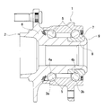
- the wheels are rotatably supported with respect to the suspension device by hub unit bearings as shown in FIG.
- the hub unit bearing shown in FIG. 4 includes an outer ring 1 that does not rotate in a state of being coupled and fixed to a suspension device in use, a hub 2 that rotates with the wheel while being supported and fixed in use, and an inner ring of the outer ring 1.
- the ball 5 is provided.
- the hub 2 includes a hub body 6 having an outer circumferential surface formed with an inner ring raceway 4a on the outer side in the axial direction (left side in FIG. 4), and an inner ring raceway 4b formed on the outer circumferential surface with the inner ring raceway in the axial direction (right side in FIG. 4).
- the inner ring 7 is connected and fixed to each other.
- the hub 2 corresponds to a shaft member. More specifically, the axial inner end portion of the cylindrical portion 8 provided at the axial inner end portion of the hub main body 6 with the inner ring 7 fitted on a portion near the inner axial end of the hub main body 6 has a diameter.
- the hub 2 is configured by plastically deforming outward in the direction to form a caulking portion 9 and pressing the inner end surface in the axial direction of the inner ring 7 by the caulking portion 9.
- the outside in the axial direction or the inside in the axial direction means the outside in the width direction or the inside in the width direction of the vehicle body when the hub unit bearing is installed in the vehicle body.
- wheels are often supported on the vehicle by a hub unit bearing using balls 5 as rolling elements.
- a hub unit bearing using balls 5 as rolling elements.
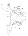
- the wheel is supported on the vehicle by a hub unit using a tapered roller 5a as a rolling element.
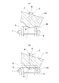
- the caulking portion 9 is formed by, for example, swing forging.
- the center axis ⁇ of the mold 15 is inclined by a predetermined angle ⁇ (for example, about 1 to 5 degrees) with respect to the center axis ⁇ of the hub body 6.
- the mold 15 is pressed against the inner end of the cylindrical portion 8 in the axial direction.
- the molding die 15 is swung or rotated around the central axis ⁇ of the hub body 6, that is, revolved.
- the molding die 15 rotates, that is, rotates around the central axis ⁇ of the molding die 15 based on the frictional force acting on the contact portion with the inner end of the cylindrical portion 8 in the axial direction.
- FIG. 3 by applying a load directed outward in the axial direction and radially outward to a part of the cylindrical portion 8 in the circumferential direction and continuously changing the portion to which the load is applied in the circumferential direction, FIG. As shown in FIG. 3, the axially inner end portion of the cylindrical portion 8 is gradually plastically deformed to form the caulking portion 9.
- the caulking portion is used to prevent creep between the hub body 6 and the inner ring 7.
- 9 is required to increase the force for holding the inner end of the inner ring 7 in the axial direction.
- the processing load for forming the caulking portion 9 becomes large. It becomes difficult to adjust the force that holds the inner end in the axial direction.
- the inner ring 7 When the force that suppresses the inner end portion of the inner ring 7 in the axial direction by the caulking portion 9 becomes excessively large, the inner ring 7 may be elastically deformed so that the inner ring raceway 4b formed on the outer peripheral surface swells in the axial direction. is there. If the inner ring 7 is elastically deformed, there arises a problem that the preload applied to the rolling element becomes unstable. In particular, the influence of elastic deformation of the inner ring 7 is significant in a hub unit bearing using a tapered roller 5a as a rolling element, as shown in FIG.
- Japanese Laid-Open Patent Publication No. 2013-91067 and Japanese Patent Laid-Open No. 2015-77616 disclose a rocking forging apparatus having a spherical seat with a shaft.
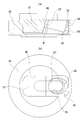
- FIG. 5 shows an example of a combined body 23 of the spherical seat 12 with shaft and the mold 15 that constitutes the swing forging device disclosed in Japanese Patent Laid-Open No. 2013-91067.
- the spherical seat 12 with a shaft includes a swing shaft 13 and a convex spherical seat 14 that is integrally formed coaxially with the swing shaft 13 at one end in the axial direction of the swing shaft 13 (lower end portion in FIG. 7).
- a molding die 15 is held and fixed so as to be coaxial with the swinging shaft 13 on one side in the axial direction of the swinging shaft 13.
- the other side portion (upper portion in FIG. 7) of the convex spherical seat 14 in the axial direction of the swing shaft 13 is spherically engaged with the concave spherical seat 16 fixed to the frame constituting the swing forging device.
- a thrust sliding bearing 42 having a partially spherical sliding surface is assembled between the axial intermediate portion of the swing shaft 13 and the frame (concave spherical seat 16).
- a driving force for oscillating and rotating the spherical seat 12 with shaft and the molding die 15 is applied to the other axial end of the oscillating shaft 13 from the drive mechanism. Further, due to the spherical engagement between the convex spherical seat 14 and the concave spherical seat 16, the rotational rotation of the spherical seat with shaft 12 and the molding die 15 is allowed, and the machining reaction force applied to the molding die 15 is supported. Further, the thrust slide bearing 42 allows the spherical seat 12 with shaft and the mold 15 to swing, and the spherical seat 12 with shaft and the mold 15 are moved with respect to the frame (drive mechanism and concave spherical seat 16). Thus, movement to one side of the swing shaft 13 in the axial direction, that is, falling off from the swing forging device is prevented.
- the shaft-side spherical seat 12 and the molding die 15 are connected to the frame (drive mechanism and concave spherical seat 16) at the connecting portion between the other axial end of the swing shaft 13 and the drive mechanism.
- the thrust sliding bearing 42 has no function to prevent the swinging shaft 13 from moving to one side in the axial direction.
- JP 2000-343905 A Japanese Patent Laid-Open No. 2003-083353 JP2013-091067A Japanese Patent Laid-Open No. 2015-077616
- a thrust sliding bearing 42 having a partially spherical sliding surface is assembled between the axially intermediate portion of the rocking shaft 13 and the frame (concave spherical seat 16). Therefore, it is necessary to secure an installation space for the thrust slide bearing 42 in the frame, and the swing forging device is enlarged accordingly. Further, since the partial spherical sliding surface provided on the thrust sliding bearing 42 is required to be formed with high accuracy, the manufacturing cost of the swing forging device increases accordingly.
- the swing angle of the molding die 15 (the inclination angle ⁇ of the central axis ⁇ of the molding die 15 with respect to the central axis ⁇ of the hub body 6) is It is preferable to set the angle to 15 degrees or more and 30 degrees or less from the viewpoint of suppressing deformation of the inner ring 7 when the caulking portion 9 is formed, and from the viewpoint of minimizing the swing forging device while suppressing the maximum processing load low. (See Japanese Patent Application Laid-Open No. 2015-77616).
- the present invention relates to an oscillating forging apparatus including a spherical seat with a shaft that oscillates and rotates together with a molding die, and the oscillating angle of the molding die can be set as large as 15 degrees to 30 degrees.
- An object of the present invention is to provide a structure capable of reducing the size and manufacturing cost of the apparatus.
- the swing forging device of the present invention includes a frame, a swing shaft, a convex spherical seat, a molding die, a concave spherical seat, and a drive mechanism.
- the frame has a reference axis.
- the swing shaft includes a central axis, an axial end on one side, and an axial end on the other side, and the central axis is disposed so as to be inclined with respect to the reference axis.
- the convex spherical seat includes one side portion in the axial direction of the swing shaft, the other side portion in the axial direction of the swing shaft, and a convex spherical portion provided on the other side portion.
- the shaft is coupled to one end portion in the axial direction so as to be coaxial with the swing shaft.
- the molding die includes a processed surface portion on one side surface in the axial direction of the swing shaft, and is coupled to the one side portion of the convex spherical seat so as to be coaxial with the swing shaft.
- the concave spherical seat includes a concave spherical surface portion that is fixed to the frame and is spherically engaged with the convex spherical surface portion, and an insertion hole through which the swing shaft is inserted.
- the moving mechanism is assembled to the frame and connected to the other axial end of the swinging shaft, and the swinging shaft and the convex spherical seat with respect to the other axial end of the swinging shaft. And a driving force for rotating the combined body of the mold and the mold around the reference axis.
- the other end portion in the axial direction of the swing shaft is supported in a state in which it is prevented from moving toward the one side in the axial direction with respect to the drive mechanism. .
- the driving mechanism is supported so as to be able to rotate about the reference axis with respect to the frame, and is provided on the rotating body, and the other side in the axial direction of the swing shaft A holding hole through which an end is inserted, and a rolling bearing provided between the holding hole and the other axial end of the swinging shaft, and the other end in the axial direction of the swinging shaft by the rolling bearing. It is possible to adopt a configuration in which the side end portion is supported in a state in which it is prevented from moving toward the one axial side with respect to the rotating body.
- the rolling bearing includes an outer ring, an inner ring, and a plurality of rolling elements disposed between the outer ring and the inner ring, and an axial load acting between the outer ring and the inner ring.
- the inner ring is externally fitted to the other axial end of the oscillating shaft in a state in which displacement to the other side in the axial direction of the oscillating shaft is prevented, and the outer ring
- the rotating body includes a case member supported so as to be able to rotate about the reference axis with respect to the frame, and a bearing holder having the holding hole.
- the structure by which the said bearing holder is detachably fixed is employable.
- the rotating body further includes a holding member that is detachably fixed to the case member in addition to the case member and the bearing holder.
- the case member has a bottomed holding recess opening on a side surface opposite to the mold in the direction of the reference axis, and a penetration formed in a part of a portion corresponding to the bottom of the holding recess. And a hole.
- the bearing holder is formed on an outer peripheral surface and a part of the outer peripheral surface in the circumferential direction, and toward the holding hole in a direction orthogonal to the reference axis as it goes to the opposite side of the mold with respect to the direction of the reference axis.
- the restraining member includes an outer peripheral surface and a second inclined surface portion that is formed on a part of the outer peripheral surface in the circumferential direction and can come into surface contact with the first inclined surface portion.
- the bearing holder and the holding member are fitted in the holding recess in a state where the first inclined surface portion and the second inclined surface portion are in contact with each other, and the holding member faces the bottom side of the holding recess.
- Directional preload is applied.
- the other axial end of the swing shaft is inserted through the through hole of the case member and the holding hole of the bearing holder.
- the inclination angle of the central axis of the swing shaft with respect to the reference axis may be 15 degrees or more and 30 degrees or less.
- the swing forging method of the present invention includes a step of plastically deforming a cylindrical portion provided at an axial end portion of a shaft member radially outward to form a caulking portion, and the swing forging device of the present invention is provided.
- the molding die is pressed against the axial end of the cylindrical portion of the shaft member in a state where the central axis of the molding die is inclined at a predetermined angle with respect to the central axis of the shaft member.
- the inclination angle of the central axis of the mold with respect to the central axis of the shaft member can be set to 15 degrees or more and 30 degrees or less.
- the hub unit bearing manufacturing method of the present invention includes an outer ring that does not rotate while being coupled and fixed to a suspension device in use, a hub that rotates and supports the wheel while being used, and an inner circumference of the outer ring.
- a plurality of rolling elements provided between a plurality of outer ring raceways provided on a surface and a plurality of inner ring raceways provided on an outer peripheral surface of the hub, the hub having an outer periphery
- a hub unit bearing wherein the inner ring is externally fitted to the axially inner end portion of the hub body using the swing forging device of the present invention. And provided at the inner end of the hub body in the axial direction. Forming a caulking portion by plastically deforming the axially inner end portion of the cylindrical portion radially outward, by the caulking portion, comprising the step of applying suppressed axially inner end face of the inner ring.
- the vehicle manufacturing method of the present invention is a method of manufacturing a vehicle having a structure in which wheels are rotatably supported by a suspension device constituting the vehicle by a hub unit bearing, and uses the hub unit bearing manufacturing method of the present invention. And a step of manufacturing the hub unit bearing.
- the other axial end of the oscillating shaft is located on one axial side with respect to the drive mechanism. It is supported in a state of being prevented from moving toward. For this reason, the support portion prevents the combined body of the swing shaft, the convex spherical seat, and the mold from moving toward one side in the axial direction with respect to the frame.
- the swinging shaft moves toward the one side in the axial direction with respect to the frame in a portion of the swinging shaft that is positioned between the convex spherical seat and the drive mechanism in the axial direction.
- a blocking member for example, a thrust sliding bearing having a partially spherical sliding surface is not assembled.
- the rocking angle of the mold which is the inclination angle of the rocking shaft with respect to the reference axis, can be set as large as 15 degrees or more and 30 degrees or less, and the apparatus can be downsized and the manufacturing cost can be reduced. Is possible.
- the rotating body constituting the drive mechanism is fixed to the case member and the case member so as to be detachable.
- the rotating body constituting the drive mechanism is fixed to the case member and the case member so as to be detachable.
- the rocking forging device and the rocking forging method of the present invention are a method for manufacturing a hub unit bearing, and a method for manufacturing a vehicle, including a step of manufacturing a hub unit bearing using the method for manufacturing a hub unit bearing. Further, it is possible to manufacture a hub in which deformation of the inner ring is suppressed, and it is possible to reduce the manufacturing cost by downsizing the device.
- FIG. 1 is a schematic cross-sectional view showing a rocking forging device according to an example of an embodiment of the present invention.
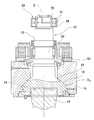
- 2A is a cross-sectional view specifically showing a part of a rotating body constituting the drive mechanism of the swing forging device of FIG. 1
- FIG. 2B is a swing forging device of FIG. It is a top view which shows a part of rotary body which comprises this drive mechanism concretely.
- FIG. 3 is an enlarged cross-sectional view of a main part sequentially illustrating steps of forming a caulking portion of the hub unit bearing by the swing forging device shown in FIG.
- FIG. 4 is a cross-sectional view showing an example of a conventionally known hub unit bearing.
- FIG. 1 is a schematic cross-sectional view showing a rocking forging device according to an example of an embodiment of the present invention.
- 2A is a cross-sectional view specifically showing a part of a rotating body constituting the drive mechanism of the swing forging device of FIG. 1
- FIG. 5 is a cross-sectional view showing another example of a conventionally known hub unit bearing.
- FIG. 6 is a cross-sectional view showing a process of forming a caulking portion of a hub unit bearing by a conventionally known swing forging device.
- FIG. 7 is a cross-sectional view showing an example of a combined body of a spherical seat with a shaft and a mold that constitutes a conventionally known rocking forging device.
- the swing forging device of this example is used to form the caulking portion 9 of the hub unit bearing shown in FIG. 4 or FIG.
- the swing forging device includes a frame 10, a lifting platform 11, a spherical seat 12 with a shaft (a swing shaft 13 and a convex spherical seat 14), a molding die 15, a concave spherical seat 16, and a drive mechanism 17.
- the frame 10 is placed on the floor of a factory or the like.
- the frame 10 has a reference axis ⁇ in the vertical direction.
- a reference axis ⁇ in the vertical direction is set on the frame 10.
- the lifting platform 11 is arranged at the lower part of the frame 10 so as to be able to move up and down along the reference axis ⁇ .
- the elevator 11 is connected to a hydraulic mechanism (not shown) for driving the elevator 11 up and down.
- a support jig 18 is provided on the upper surface of the elevator 11 to support the hub main body 6 that is a workpiece without rattling in the radial direction.
- the spherical seat 12 with a shaft has a central axis ⁇ and extends along the central axis ⁇ , and one axial end of the swinging shaft 13 (the lower end in FIG. 1)
- a oscillating shaft 13 and a convex spherical seat 14 coupled coaxially are provided.
- the spherical seat with shaft 12 is installed above the elevator 11 in the frame 10 with the central axis ⁇ inclined by a predetermined angle ⁇ with respect to the reference axis ⁇ .
- the convex spherical seat 14 is coupled to the oscillating shaft 13 on the other side (the upper side in FIG. 1) side in the axial direction of the oscillating shaft 13.
- the other side portion of the convex spherical seat 14 in the axial direction of the swing shaft 13 is constituted by a convex spherical portion 19 except for a portion coupled to the swing shaft 13.
- the center of curvature of the convex spherical surface portion 19 exists on the central axis ⁇ of the swing shaft 13. For this reason, the rocking shaft 13 and the convex spherical seat 14 are disposed simultaneously.
- Such a shaft-attached spherical seat 12 may be integrally formed as a whole, or may be configured by combining a plurality of components.
- the forming die 15 is coaxially coupled to the oscillating shaft 13 on one side of the convex spherical seat 14 in the axial direction of the oscillating shaft 13.
- one side surface in the axial direction of the oscillating shaft 13 is constituted by an annular processed surface portion 20 that is coaxial with the central axis ⁇ of the oscillating shaft 13.
- Such a mold 15 may be configured separately from the spherical seat with shaft 12, or may be configured integrally with a part of the spherical seat with shaft 12 or a part of the spherical seat with shaft 12. May be.
- the concave spherical seat 16 is fixed to an intermediate portion in the vertical direction in the frame 10.
- the concave spherical seat 16 includes a concave spherical portion 22 that is spherically engaged with the convex spherical portion 19 of the convex spherical seat 14, and one axial end of the oscillating shaft 13 provided at the center of the concave spherical portion 22. And an insertion hole 21 through which the part is inserted.
- the center of curvature of the concave spherical portion 22 exists on the reference axis ⁇ .
- the insertion hole 21 of the concave spherical seat 16 is constituted by a tapered hole whose inner diameter dimension increases toward the upper side.
- a portion of the inner peripheral surface of the frame 10 that is adjacent to the upper part of the insertion hole 21 of the concave spherical seat 16 and through which the intermediate portion in the axial direction of the swing shaft 13 is inserted has an inner diameter dimension as it goes upward.
- the inner diameter dimensions of the insertion hole 21 and the stepped hole 24 are such that when the joined body 23 of the molding die 15 and the spherical seat 12 with the shaft oscillates and rotates about the reference axis ⁇ , the oscillating shaft.
- the reason why the portion adjacent to the upper part of the insertion hole 21 in the inner peripheral surface of the frame 10 is the stepped hole 24 is that the ease of processing when using general processing equipment is taken into consideration. It is.
- the stepped hole 24 can be changed to a tapered hole whose inner diameter dimension increases toward the upper side as long as it can be processed.
- the drive mechanism 17 is assembled to the upper end portion in the frame 10.
- the driving mechanism 17 is connected to the other end portion in the axial direction of the swinging shaft 13 protruding upward from the stepped hole 24.
- the drive mechanism 17 provides a driving force for the combined body 23 of the mold 15 and the spherical seat with shaft 12 to swing and rotate about the reference axis ⁇ with respect to the other axial end of the swing shaft 13. Give.
- the drive mechanism 17 includes a rotating body 26, a holding hole 27, and a rolling bearing 28.
- the rotating body 26 is supported by the bearing device 25 inside the upper end portion of the frame 10 so as to be able to rotate only about the reference axis ⁇ .
- An output unit of a motor (not shown) for rotating the rotary body 26 is connected to the rotating body 26 directly or via a speed reducer (not shown).
- the holding hole 27 is provided in a part of the circumferential direction of the intermediate portion in the radial direction of the rotating body 26.
- the central axis of the holding hole 27 is inclined with respect to the reference axis ⁇ by substantially the same angle as the inclination angle ⁇ .
- the rolling bearing 28 is disposed between the inner peripheral surface of the holding hole 27 and the outer peripheral surface of the other axial end of the swing shaft 13, and the other axial direction of the swing shaft 13 with respect to the holding hole 27.
- the side end is rotatably supported.
- the rolling bearing 28 prevents the other end portion in the axial direction of the oscillating shaft 13 from moving toward the one side in the axial direction with respect to the drive mechanism 17 (dropping downward in FIG. 1). It is supported in the state that was done.
- the rolling bearing 28 Since the rolling bearing 28 has a function of preventing the rolling bearing 28 from moving toward one side in the axial direction, the rolling bearing 28 has a configuration having an axial load supporting capability in addition to a radial load supporting capability.
- a self-aligning roller bearing is used as the rolling bearing 28.
- a plurality of spherical rollers 31 are arranged in a freely rolling manner between the inner peripheral surface of the outer ring 29 and the outer peripheral surface of the inner ring 30, and the plurality of spherical surfaces are provided by a cage (not shown). The posture and position of the roller 31 are restricted.
- the rolling bearing 28 can support a radial load acting between the outer ring 29 and the inner ring 30 and can support an axial load acting between the outer ring 29 and the inner ring 30. Further, even when the central axes of the outer ring 29 and the inner ring 30 are slightly inclined, the self-aligning property is such that the rolling of the spherical roller 31 between the outer ring 29 and the inner ring 30 can be performed smoothly. Have. Since the specific configuration of such a self-aligning roller bearing is already known, the description thereof is omitted. When the present invention is carried out, a deep groove ball bearing, an angular ball bearing, or the like can be used as the rolling bearing 28.
- the outer ring 29 is fitted in the holding hole 27 in a state where displacement to one side in the axial direction of the swing shaft 13 is prevented.
- the inner peripheral surface of the holding hole 27 is constituted by a stepped hole having a step surface 32 facing the other side in the axial direction (the upper side in FIG. 1) in the axially intermediate portion.
- the outer ring 29 is fitted in a portion of the holding hole 27 located on the other side in the axial direction with respect to the step surface 32 without rattling, and the end surface on the one side in the axial direction of the outer ring 29 is in contact with the step surface 32. .
- the inner ring 30 is fitted on the other end of the swing shaft 13 in the axial direction while preventing displacement of the swing shaft 13 in the other direction with respect to the axial direction. Therefore, the inner ring 30 is externally fitted to the other axial end of the swinging shaft 13 without rattling, and the nut 34 is fitted to the male screw portion 33 provided at the other axial end of the swinging shaft 13. And the nut 34 is in contact with the other axial end surface of the inner ring 30.
- the distance between the nut 34 and the convex spherical seat 14 is adjusted, so that the machining surface portion 20 of the molding die 15 is replaced with the cylindrical portion of the hub body 6.
- the configuration in which the end surface on the one side in the axial direction of the outer ring 29 is in contact with the stepped surface 32 for example, the configuration in which the outer ring is fitted into the holding hole by interference fitting or the both ends of the outer ring in the axial direction are swung.
- Adopting a structure in which a nut screwed to the holding hole and a retaining ring locked to the holding hole are brought into contact with one end face in the axial direction of the shaft Adopting a structure in which a nut screwed to the holding hole and a retaining ring locked to the holding hole are brought into contact with one end face in the axial direction of the shaft, the outer ring fitted in the holding hole swings. It is also possible to prevent displacement to one side with respect to the axial direction of the shaft.
- the rotating body 26 includes a case member 35 and a bearing holder 36 and a holding member 37 that are detachably fixed to the case member 35. Prepare.
- the case member 35 constitutes the lower part of the rotating body 26, has a thick disk shape, and is arranged coaxially with respect to the reference axis ⁇ .
- the case member 35 has a bottomed holding recess 38 that opens to the upper side surface, which is the side surface opposite to the mold 15.
- the shape of the holding recess 38 viewed from above is a long rectangle extending in the radial direction with the reference axis ⁇ as the center.
- the case member 35 has a through hole 39 in a part of the portion corresponding to the bottom of the holding recess 38. This through hole 39 is also provided in a state of extending in the same direction as the extending direction of the holding recess 38.
- the bearing holder 36 is fitted into the longitudinal half of the holding recess 38 on one side (the right half in FIG. 2) without rattling.
- the holding member 37 is fitted in the other half in the longitudinal direction of the holding recess 38 (the left half in FIG. 2) without rattling.
- the bearing holder 36 has a substantially square cylindrical shape, and a holding hole 27 is provided on the radially inner side.
- the first inclined surface portion 40 is provided at the other end (left side in FIG. 2A) in the longitudinal direction of the holding recess 38.
- the first inclined surface portion 40 is perpendicular to the reference axis ⁇ as it goes to the side opposite to the mold 15 (upper side in FIG. 2A) with respect to the direction of the reference axis ⁇ (vertical direction in FIG. 2A). It is inclined in the direction toward the holding hole 27 with respect to the left-right direction in FIG.
- the first inclined surface portion 40 is inclined by the same angle in the same direction as the holding hole 27.
- the holding member 37 has a substantially rectangular parallelepiped shape, and the second inclined surface portion 41 is formed at the end of one side (the right side in FIG. 2A) in the longitudinal direction of the holding recess 38 in the outer circumferential surface of the holding member 37. Is provided.
- the second inclined surface portion 41 is inclined by the same angle in the same direction as the first inclined surface portion 40 and is in surface contact with the first inclined surface portion 40.
- a preload in a direction toward the bottom side of the holding recess 38 (the lower side in FIG. 2A) is applied to the holding member 37 by a tightening force of a holding bolt (not shown).
- a holding bolt (not shown).
- a wedge effect is generated in the engaging portion between the first inclined surface portion 40 and the second inclined surface portion 41, and the position of the bearing holder 36 is strictly regulated with respect to the holding recess 38.
- the axial force is applied to the holding bolt due to the elastic deformation of the holding member 37, it is possible to effectively prevent the holding bolt from being loosened even by vibrations generated during swing forging. Is done.
- the upper surface of the holding member 37 is held down by a lid member coupled and fixed to the case member 35 with a bolt or the like, thereby preventing the holding member 37 from floating upward.
- a configuration can also be employed.
- the bearing holder 36 and the holding member 37 are detachably fixed to the case member 35 based on the attachment and detachment of the holding bolt and the lid member described above.
- the other axial end of the swing shaft 13 is inserted into the holding hole 27 of the bearing holder 36 through the through hole 39 of the case member 35.
- the swinging shaft 13 moves toward the one side in the axial direction with respect to the frame 10. 1, that is, a combined body 23 of the molding die 15 and the spherical seat with shaft 12 moves toward one side in the axial direction of the swing shaft 13 with respect to the frame 10 (below in FIG. 1).
- a thrust sliding bearing having a partially spherical sliding surface is not assembled.
- the tilt angle ⁇ which is the swing angle of the mold 15 when performing swing forging, is set to 15 degrees or more and 30 degrees or less.
- the swinging shaft 13 is connected to the frame 10 at the connecting portion at the other axial end of the driving mechanism 17 and the swinging shaft 13 in spite of having such a large inclination angle ⁇ . Since a mechanism for preventing movement toward one side in the axial direction is provided, a space for arranging a member such as a thrust slide bearing in the frame 10 is unnecessary. For this reason, size reduction and cost reduction of an apparatus are achieved.
- the caulking portion 9 When the caulking portion 9 is formed on the inner end in the axial direction of the hub body 6 using the swing forging device of this example having such a configuration, the caulking portion 9 is formed as shown in FIG.
- the hub body 6 In the assembled state of the previous hub body 6 and other parts constituting the hub unit bearing, the hub body 6 does not rattle in the radial direction by the support jig 18 provided on the upper surface of the lifting platform 11. And it supports in the state which made the center axis
- the lifting platform 11 is raised, and a part of the processing surface portion 20 of the mold 15 in the circumferential direction is provided at the inner end of the hub body 6 in the axial direction as shown in FIG.
- the cylindrical portion 8 is pressed against a part in the circumferential direction at the inner end in the axial direction.
- the rotating body 26 is rotated about the reference axis ⁇ , and the combined body 23 of the mold 15 and the spherical seat 12 with the shaft is moved around the reference axis ⁇ , that is, the reference axis ⁇ and the combined body 23. Oscillating and rotating with reference to the intersection point P with the central axis ⁇ .
- a proximity sensor (not shown) is provided in the rocking forging device, and the proximity sensor is provided at a part in the circumferential direction of the machining surface portion 20 of the mold 15 and the inner end in the axial direction of the hub body 6.
- the distance between the axially inner end portion of the provided cylindrical portion 8 and a part in the circumferential direction is measured, and when the predetermined distance is reached, that is, the mold 15 and the cylindrical portion 8 are completely in contact with each other. It is also possible to start the swinging rotation of the combined body 23 in the previous approached state.
- the joined body 23 of the mold 15 and the spherical seat 12 with the shaft is based on the frictional force acting on the contact portion between the cylindrical portion 8 and the inner end in the axial direction. Rotates around the center, that is, rotates. As a result, a load directed outward in the axial direction and outward in the radial direction is applied to a part of the cylindrical portion 8 in the circumferential direction.
- the axially inner end of the cylindrical portion 8 is gradually plastically deformed as shown in order from FIG. 3 (a) to FIG. 3 (b).
- the caulking portion 9 is formed.
- the rocking angle (inclination angle ⁇ ) of the forming die 15 when forming the caulking portion 9 is set to 15 degrees or more and 30 degrees or less by such rocking forging.
- the maximum processing load when performing dynamic forging can be kept low.
- the inclination angle ⁇ is constant during the swing forging process.
- the inclination angle ⁇ is set to 15 degrees or more and 30 degrees or less, and the swing forging using the proximity sensor is performed.
- the processing load for forming the caulking portion 9 can be reduced, and the inner ring 7 is formed on the outer peripheral surface. It is possible to prevent the inner ring raceway 4b on the inner side in the axial direction from being elastically deformed so as to bulge.
- the other end portion in the axial direction of the oscillating shaft 13 is supported in a state in which it is prevented from moving toward the one axial side with respect to the drive mechanism 17. For this reason, by this support portion, the combined body 23 of the mold 15 and the spherical seat with shaft 12 moves toward the axial direction one side of the swing shaft 13 with respect to the frame 10 (drops downward in FIG. 1). ) Is prevented. Further, the swinging shaft 13 moves toward the one side in the axial direction with respect to the frame 10 in a portion of the swinging shaft 13 located between the convex spherical seat 14 and the drive mechanism 17 in the axial direction.
- a blocking member for example, a thrust sliding bearing having a partially spherical sliding surface is not assembled. Therefore, it is possible to reduce the size of the swing forging device and reduce the manufacturing cost accordingly.
- the bearing holder 36 and the holding member 37 are detachably fixed to the case member 35. Therefore, by changing the bearing holder 36 and the holding member 37 and changing the inclination angle of the holding hole 27, the swing angle (inclination angle ⁇ ) of the mold 15 can be changed in a wide range. . Therefore, it is possible to select the optimal swing angle ⁇ according to the type of workpiece (for example, the hub body 6).
- the insertion position of the swing shaft 13 with respect to the through hole 39 of the case member 35 changes according to the swing angle (inclination angle ⁇ ) of the mold 15.
Landscapes
- Engineering & Computer Science (AREA)
- Mechanical Engineering (AREA)
- General Engineering & Computer Science (AREA)
- Forging (AREA)
- Rolling Contact Bearings (AREA)
- Mounting Of Bearings Or Others (AREA)
Priority Applications (6)
| Application Number | Priority Date | Filing Date | Title |
|---|---|---|---|
| EP18761668.5A EP3590624B1 (de) | 2017-03-02 | 2018-02-28 | Taumelpressvorrichtung, taumelpressverfahren, verfahren zur herstellung einer nabeneinheit mithilfe des taumelpressverfahrens und fahrzeugherstellungsverfahren |
| JP2019503057A JP6566167B2 (ja) | 2017-03-02 | 2018-02-28 | 揺動鍛造装置、揺動鍛造方法、該揺動鍛造方法を用いたハブユニット軸受の製造方法および車両の製造方法 |
| KR1020197021474A KR102522747B1 (ko) | 2017-03-02 | 2018-02-28 | 요동 단조 장치, 요동 단조 방법, 그 요동 단조 방법을 이용한 허브 유닛 베어링의 제조 방법 및 차량의 제조 방법 |
| CN201880012186.9A CN110290885B (zh) | 2017-03-02 | 2018-02-28 | 摆动锻造装置、摆动锻造方法、使用了该摆动锻造方法的轮毂单元轴承的制造方法以及车辆的制造方法 |
| US16/490,305 US11103917B2 (en) | 2017-03-02 | 2018-02-28 | Orbital forging device, method for orbital forging, method for manufacturing hub unit bearing using method for orbital forging, and method for manufacturing vehicle |
| US17/347,718 US11904383B2 (en) | 2017-03-02 | 2021-06-15 | Orbital forging device, method for orbital forging, method for manufacturing hub unit bearing using method for orbital forging, and method for manufacturing vehicle |
Applications Claiming Priority (2)
| Application Number | Priority Date | Filing Date | Title |
|---|---|---|---|
| JP2017038933 | 2017-03-02 | ||
| JP2017-038933 | 2017-03-02 |
Related Child Applications (2)
| Application Number | Title | Priority Date | Filing Date |
|---|---|---|---|
| US16/490,305 A-371-Of-International US11103917B2 (en) | 2017-03-02 | 2018-02-28 | Orbital forging device, method for orbital forging, method for manufacturing hub unit bearing using method for orbital forging, and method for manufacturing vehicle |
| US17/347,718 Division US11904383B2 (en) | 2017-03-02 | 2021-06-15 | Orbital forging device, method for orbital forging, method for manufacturing hub unit bearing using method for orbital forging, and method for manufacturing vehicle |
Publications (1)
| Publication Number | Publication Date |
|---|---|
| WO2018159670A1 true WO2018159670A1 (ja) | 2018-09-07 |
Family
ID=63369927
Family Applications (1)
| Application Number | Title | Priority Date | Filing Date |
|---|---|---|---|
| PCT/JP2018/007486 WO2018159670A1 (ja) | 2017-03-02 | 2018-02-28 | 揺動鍛造装置、揺動鍛造方法、該揺動鍛造方法を用いたハブユニット軸受の製造方法および車両の製造方法 |
Country Status (6)
| Country | Link |
|---|---|
| US (2) | US11103917B2 (de) |
| EP (1) | EP3590624B1 (de) |
| JP (3) | JP6566167B2 (de) |
| KR (1) | KR102522747B1 (de) |
| CN (1) | CN110290885B (de) |
| WO (1) | WO2018159670A1 (de) |
Cited By (1)
| Publication number | Priority date | Publication date | Assignee | Title |
|---|---|---|---|---|
| US20220055089A1 (en) * | 2019-04-10 | 2022-02-24 | Nsk Ltd. | Method of manufacturing staking assembly, method of manufacturing hub unit bearing, staking device, staking assembly, and method of manufacturing vehicle |
Families Citing this family (5)
| Publication number | Priority date | Publication date | Assignee | Title |
|---|---|---|---|---|
| CN111971133B (zh) * | 2018-02-13 | 2022-07-19 | 日本精工株式会社 | 摆动锻造装置的动态载荷测定及校正方法、动态载荷测定装置、轮毂单元轴承和车辆的制造方法 |
| CN110918849B (zh) * | 2019-11-26 | 2020-12-22 | 武汉理工大学 | 一种提高薄壁高筋构件空间包络成形高筋成形极限的方法 |
| CN111181344B (zh) * | 2020-01-08 | 2020-11-03 | 上海交通大学 | 摆动式表面显微冷锻装置 |
| CN112916782B (zh) * | 2021-02-07 | 2023-06-20 | 哈尔滨工业大学 | 一种带有局部突变特征的超长薄腹板高筋复杂构件的局部渐进加载精密成形模具及方法 |
| CN117086251B (zh) * | 2023-10-16 | 2024-01-05 | 常州市科宇重工科技有限公司 | 一种铸锻件成型锻打装置 |
Citations (7)
| Publication number | Priority date | Publication date | Assignee | Title |
|---|---|---|---|---|
| JPS5048841U (de) * | 1973-09-04 | 1975-05-14 | ||
| JPS60227939A (ja) * | 1984-04-21 | 1985-11-13 | ハインリツヒ・シユミツト・マシネン‐ウント・ヴエルクツオイクバウ・アーゲー | 揺動ダイ鍛造機械 |
| JP2000343905A (ja) | 1999-06-02 | 2000-12-12 | Nsk Ltd | 車輪支持用転がり軸受ユニットの組立方法 |
| JP2003083353A (ja) | 2001-07-03 | 2003-03-19 | Nsk Ltd | 車輪支持用転がり軸受ユニットの製造方法及び製造装置 |
| JP2013091067A (ja) | 2011-10-24 | 2013-05-16 | Toyota Motor Corp | 揺動鍛造装置及び揺動鍛造方法 |
| JP2015077616A (ja) | 2013-10-17 | 2015-04-23 | 日本精工株式会社 | 車輪支持用転がり軸受ユニットの製造方法 |
| JP2017002926A (ja) * | 2015-06-05 | 2017-01-05 | 日本精工株式会社 | 車輪支持用転がり軸受ユニットの製造方法 |
Family Cites Families (28)
| Publication number | Priority date | Publication date | Assignee | Title |
|---|---|---|---|---|
| GB319065A (en) | 1928-05-19 | 1929-09-19 | Massey Ltd B & S | Improvements in forging and upsetting machines |
| DE1652653B1 (de) * | 1967-01-20 | 1972-05-31 | Politechnika Warszawska | Walzgesenkpresse |
| FR1560475A (de) | 1968-01-18 | 1969-03-21 | ||
| SU517514A1 (ru) | 1974-07-24 | 1976-06-15 | Ижевский механический институт | Устройство дл штамповки заготовок |
| DE3202254C2 (de) * | 1982-01-25 | 1986-02-20 | Zahnradfabrik Friedrichshafen Ag, 7990 Friedrichshafen | Verfahren und Vorrichtung zum Herstellen einer Zahnstange |
| JPH01317650A (ja) | 1988-06-20 | 1989-12-22 | Sumitomo Heavy Ind Ltd | 揺動鍛造機 |
| JPH02197345A (ja) | 1989-01-24 | 1990-08-03 | Mitsubishi Nagasaki Kiko Kk | 回転揺動鍛造機の回転揺動軸の回転ずれ防止装置 |
| JPH0730193Y2 (ja) | 1989-02-09 | 1995-07-12 | 三菱長崎機工株式会社 | 回転揺動鍛造機の回転揺動軸の傾斜角度自動調整装置 |
| JPH02251330A (ja) | 1989-02-14 | 1990-10-09 | Brother Ind Ltd | 鍛造方法 |
| US4982589A (en) | 1989-02-14 | 1991-01-08 | Brother Kogyo Kabushiki Kaisha | Swiveling type plastic working machine |
| JPH04200947A (ja) * | 1990-11-30 | 1992-07-21 | Fuji Car Mfg Co Ltd | 揺動鍛造プレス機 |
| CN2134900Y (zh) * | 1992-09-26 | 1993-06-02 | 许德安 | 直线摆动辗压机 |
| GB9300529D0 (en) * | 1993-01-13 | 1993-03-03 | Penny & Giles Blackwood Ltd | Improvements in rotary forging |
| JPH06285576A (ja) * | 1993-04-02 | 1994-10-11 | Citizen Watch Co Ltd | 揺動鍛造パンチの製造装置及び揺動鍛造パンチの製造方法 |
| JP4852922B2 (ja) * | 2005-07-26 | 2012-01-11 | 株式会社ジェイテクト | ラック軸の製造方法 |
| CN2898424Y (zh) * | 2006-05-12 | 2007-05-09 | 朱申明 | 振动筛轴承外圈胀套式固定结构 |
| JP5261023B2 (ja) * | 2008-05-13 | 2013-08-14 | Ntn株式会社 | 車輪用軸受装置の加工方法 |
| JP2012045612A (ja) * | 2010-08-30 | 2012-03-08 | Jtekt Corp | 車両用ハブユニットの製造方法 |
| JP2012197932A (ja) * | 2011-03-07 | 2012-10-18 | Jtekt Corp | 車輪用転がり軸受装置の製造方法 |
| JP2012183562A (ja) * | 2011-03-07 | 2012-09-27 | Jtekt Corp | 車輪用転がり軸受装置の軸部材の製造方法 |
| US8590657B2 (en) | 2011-12-09 | 2013-11-26 | GM Global Technology Operations LLC | Vehicle wheel assembly having a self-retaining bearing |
| US9103375B2 (en) * | 2012-12-14 | 2015-08-11 | Aktiebolaget Skf | Cartridge bearing assembly |
| JP6026374B2 (ja) * | 2013-09-02 | 2016-11-16 | 住友重機械工業株式会社 | 鍛造用スイングプレス |
| CN203944773U (zh) * | 2014-06-23 | 2014-11-19 | 徐州达一锻压设备有限公司 | 摆动碾压机的球面摆头装置 |
| JP6379798B2 (ja) * | 2014-07-25 | 2018-08-29 | 日本精工株式会社 | 転がり軸受ユニットの製造方法及び車両の製造方法 |
| JP6464625B2 (ja) | 2014-09-15 | 2019-02-06 | 株式会社ジェイテクト | ハブユニット製造装置 |
| JP6222177B2 (ja) * | 2015-07-13 | 2017-11-01 | 日本精工株式会社 | 転がり軸受ユニットの製造方法、車両の製造方法 |
| JP6160715B2 (ja) * | 2016-01-07 | 2017-07-12 | 日本精工株式会社 | 車輪支持用転がり軸受ユニット |
-
2018
- 2018-02-28 CN CN201880012186.9A patent/CN110290885B/zh active Active
- 2018-02-28 EP EP18761668.5A patent/EP3590624B1/de active Active
- 2018-02-28 US US16/490,305 patent/US11103917B2/en active Active
- 2018-02-28 KR KR1020197021474A patent/KR102522747B1/ko active IP Right Grant
- 2018-02-28 WO PCT/JP2018/007486 patent/WO2018159670A1/ja unknown
- 2018-02-28 JP JP2019503057A patent/JP6566167B2/ja active Active
-
2019
- 2019-07-05 JP JP2019125653A patent/JP6835154B2/ja active Active
-
2020
- 2020-11-09 JP JP2020186660A patent/JP7243703B2/ja active Active
-
2021
- 2021-06-15 US US17/347,718 patent/US11904383B2/en active Active
Patent Citations (7)
| Publication number | Priority date | Publication date | Assignee | Title |
|---|---|---|---|---|
| JPS5048841U (de) * | 1973-09-04 | 1975-05-14 | ||
| JPS60227939A (ja) * | 1984-04-21 | 1985-11-13 | ハインリツヒ・シユミツト・マシネン‐ウント・ヴエルクツオイクバウ・アーゲー | 揺動ダイ鍛造機械 |
| JP2000343905A (ja) | 1999-06-02 | 2000-12-12 | Nsk Ltd | 車輪支持用転がり軸受ユニットの組立方法 |
| JP2003083353A (ja) | 2001-07-03 | 2003-03-19 | Nsk Ltd | 車輪支持用転がり軸受ユニットの製造方法及び製造装置 |
| JP2013091067A (ja) | 2011-10-24 | 2013-05-16 | Toyota Motor Corp | 揺動鍛造装置及び揺動鍛造方法 |
| JP2015077616A (ja) | 2013-10-17 | 2015-04-23 | 日本精工株式会社 | 車輪支持用転がり軸受ユニットの製造方法 |
| JP2017002926A (ja) * | 2015-06-05 | 2017-01-05 | 日本精工株式会社 | 車輪支持用転がり軸受ユニットの製造方法 |
Cited By (1)
| Publication number | Priority date | Publication date | Assignee | Title |
|---|---|---|---|---|
| US20220055089A1 (en) * | 2019-04-10 | 2022-02-24 | Nsk Ltd. | Method of manufacturing staking assembly, method of manufacturing hub unit bearing, staking device, staking assembly, and method of manufacturing vehicle |
Also Published As
| Publication number | Publication date |
|---|---|
| JP2019181571A (ja) | 2019-10-24 |
| JP6835154B2 (ja) | 2021-02-24 |
| JPWO2018159670A1 (ja) | 2019-06-27 |
| JP2021013960A (ja) | 2021-02-12 |
| KR102522747B1 (ko) | 2023-04-17 |
| CN110290885A (zh) | 2019-09-27 |
| US20210308744A1 (en) | 2021-10-07 |
| EP3590624A4 (de) | 2020-07-29 |
| JP7243703B2 (ja) | 2023-03-22 |
| JP6566167B2 (ja) | 2019-08-28 |
| KR20190122654A (ko) | 2019-10-30 |
| US11904383B2 (en) | 2024-02-20 |
| CN110290885B (zh) | 2023-09-19 |
| US11103917B2 (en) | 2021-08-31 |
| EP3590624B1 (de) | 2023-06-28 |
| EP3590624A1 (de) | 2020-01-08 |
| US20200009642A1 (en) | 2020-01-09 |
Similar Documents
| Publication | Publication Date | Title |
|---|---|---|
| JP6566167B2 (ja) | 揺動鍛造装置、揺動鍛造方法、該揺動鍛造方法を用いたハブユニット軸受の製造方法および車両の製造方法 | |
| JP2019181571A5 (de) | ||
| JP6624354B1 (ja) | 揺動加工装置、ハブユニット軸受の製造方法および自動車の製造方法 | |
| CN111971133B (zh) | 摆动锻造装置的动态载荷测定及校正方法、动态载荷测定装置、轮毂单元轴承和车辆的制造方法 | |
| WO2017010481A1 (ja) | 軸受ユニットの製造方法及び製造装置 | |
| US11745249B2 (en) | Rotary caulking device, method of manufacturing hub unit bearing and method of manufacturing vehicle | |
| JP2019211084A (ja) | ハブユニット軸受およびその製造方法、並びに、自動車およびその製造方法 | |
| JP6222197B2 (ja) | 転がり軸受ユニットの製造方法及び製造装置、車両の製造方法 | |
| KR20190007490A (ko) | 차륜 지지용 베어링 유닛의 제조 방법 및 제조 장치, 그리고 차량의 제조 방법 | |
| JP4096617B2 (ja) | ボルト取付補助具 | |
| KR20210148142A (ko) | 스웨이징 어셈블리의 제조 방법, 허브 유닛 베어링의 제조 방법, 스웨이징 장치, 스웨이징 어셈블리 및 차량의 제조 방법 | |
| JP2017067254A5 (de) | ||
| US20230296136A1 (en) | Staking apparatus and staking method for bearing unit, manufacturing method and manufacturing apparatus of hub unit bearing, and manufacturing method of vehicle |
Legal Events
| Date | Code | Title | Description |
|---|---|---|---|
| 121 | Ep: the epo has been informed by wipo that ep was designated in this application |
Ref document number: 18761668 Country of ref document: EP Kind code of ref document: A1 |
|
| ENP | Entry into the national phase |
Ref document number: 2019503057 Country of ref document: JP Kind code of ref document: A |
|
| ENP | Entry into the national phase |
Ref document number: 20197021474 Country of ref document: KR Kind code of ref document: A |
|
| NENP | Non-entry into the national phase |
Ref country code: DE |
|
| ENP | Entry into the national phase |
Ref document number: 2018761668 Country of ref document: EP Effective date: 20191002 |