EP3590624B1 - Taumelpressvorrichtung, taumelpressverfahren, verfahren zur herstellung einer nabeneinheit mithilfe des taumelpressverfahrens und fahrzeugherstellungsverfahren - Google Patents
Taumelpressvorrichtung, taumelpressverfahren, verfahren zur herstellung einer nabeneinheit mithilfe des taumelpressverfahrens und fahrzeugherstellungsverfahren Download PDFInfo
- Publication number
- EP3590624B1 EP3590624B1 EP18761668.5A EP18761668A EP3590624B1 EP 3590624 B1 EP3590624 B1 EP 3590624B1 EP 18761668 A EP18761668 A EP 18761668A EP 3590624 B1 EP3590624 B1 EP 3590624B1
- Authority
- EP
- European Patent Office
- Prior art keywords
- section
- axial direction
- swinging shaft
- inner ring
- molding die
- Prior art date
- Legal status (The legal status is an assumption and is not a legal conclusion. Google has not performed a legal analysis and makes no representation as to the accuracy of the status listed.)
- Active
Links
Images


Classifications
-
- B—PERFORMING OPERATIONS; TRANSPORTING
- B21—MECHANICAL METAL-WORKING WITHOUT ESSENTIALLY REMOVING MATERIAL; PUNCHING METAL
- B21K—MAKING FORGED OR PRESSED METAL PRODUCTS, e.g. HORSE-SHOES, RIVETS, BOLTS OR WHEELS
- B21K1/00—Making machine elements
- B21K1/04—Making machine elements ball-races or sliding bearing races
-
- B—PERFORMING OPERATIONS; TRANSPORTING
- B21—MECHANICAL METAL-WORKING WITHOUT ESSENTIALLY REMOVING MATERIAL; PUNCHING METAL
- B21J—FORGING; HAMMERING; PRESSING METAL; RIVETING; FORGE FURNACES
- B21J9/00—Forging presses
- B21J9/02—Special design or construction
- B21J9/025—Special design or construction with rolling or wobbling dies
-
- B—PERFORMING OPERATIONS; TRANSPORTING
- B21—MECHANICAL METAL-WORKING WITHOUT ESSENTIALLY REMOVING MATERIAL; PUNCHING METAL
- B21K—MAKING FORGED OR PRESSED METAL PRODUCTS, e.g. HORSE-SHOES, RIVETS, BOLTS OR WHEELS
- B21K1/00—Making machine elements
- B21K1/28—Making machine elements wheels; discs
- B21K1/40—Making machine elements wheels; discs hubs
-
- B—PERFORMING OPERATIONS; TRANSPORTING
- B21—MECHANICAL METAL-WORKING WITHOUT ESSENTIALLY REMOVING MATERIAL; PUNCHING METAL
- B21K—MAKING FORGED OR PRESSED METAL PRODUCTS, e.g. HORSE-SHOES, RIVETS, BOLTS OR WHEELS
- B21K25/00—Uniting components to form integral members, e.g. turbine wheels and shafts, caulks with inserts, with or without shaping of the components
-
- F—MECHANICAL ENGINEERING; LIGHTING; HEATING; WEAPONS; BLASTING
- F16—ENGINEERING ELEMENTS AND UNITS; GENERAL MEASURES FOR PRODUCING AND MAINTAINING EFFECTIVE FUNCTIONING OF MACHINES OR INSTALLATIONS; THERMAL INSULATION IN GENERAL
- F16C—SHAFTS; FLEXIBLE SHAFTS; ELEMENTS OR CRANKSHAFT MECHANISMS; ROTARY BODIES OTHER THAN GEARING ELEMENTS; BEARINGS
- F16C23/00—Bearings for exclusively rotary movement adjustable for aligning or positioning
- F16C23/06—Ball or roller bearings
- F16C23/08—Ball or roller bearings self-adjusting
-
- F—MECHANICAL ENGINEERING; LIGHTING; HEATING; WEAPONS; BLASTING
- F16—ENGINEERING ELEMENTS AND UNITS; GENERAL MEASURES FOR PRODUCING AND MAINTAINING EFFECTIVE FUNCTIONING OF MACHINES OR INSTALLATIONS; THERMAL INSULATION IN GENERAL
- F16C—SHAFTS; FLEXIBLE SHAFTS; ELEMENTS OR CRANKSHAFT MECHANISMS; ROTARY BODIES OTHER THAN GEARING ELEMENTS; BEARINGS
- F16C35/00—Rigid support of bearing units; Housings, e.g. caps, covers
-
- F—MECHANICAL ENGINEERING; LIGHTING; HEATING; WEAPONS; BLASTING
- F16—ENGINEERING ELEMENTS AND UNITS; GENERAL MEASURES FOR PRODUCING AND MAINTAINING EFFECTIVE FUNCTIONING OF MACHINES OR INSTALLATIONS; THERMAL INSULATION IN GENERAL
- F16C—SHAFTS; FLEXIBLE SHAFTS; ELEMENTS OR CRANKSHAFT MECHANISMS; ROTARY BODIES OTHER THAN GEARING ELEMENTS; BEARINGS
- F16C2326/00—Articles relating to transporting
- F16C2326/01—Parts of vehicles in general
- F16C2326/02—Wheel hubs or castors
Definitions
- the present invention relates to an orbital forging device and a method for orbital forging which are used for forming a crimped portion by plastically deforming a cylindrical section provided in an end section in the axial direction of a shaft member such as a hub outward in the radial direction.
- the present invention also relates to a method for manufacturing a hub unit bearing using this method for orbital forging, and a method for manufacturing a vehicle using this method for manufacturing a hub unit bearing.
- An orbital forging device according to the preamble of claim 1 is known, for example, from JP H02 108537 U .
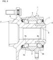
- wheels are rotatably supported to a suspension respectively by a hub unit bearing such as illustrated in FIG. 4 .
- the hub unit bearing illustrated in FIG. 4 comprises an outer ring 1 that does not rotate in use with connected and fastened to a suspension, a hub 2 that rotates in use with a wheel supported and fixed thereto, and balls 5 as a plurality of rolling elements that are rollably provided between double-row outer ring raceways 3a, 3b provided on the inner circumferential surface of the outer ring 1 and double-row inner ring raceways 4a, 4b provided on the outer circumferential surface of the hub 2.
- the hub 2 is constructed by connecting and fastening a hub body 6 in which the inner ring raceway 4a on the outside (left side in FIG.4 ) in the axial direction is formed on the outer circumferential surface and an inner ring 7 in which the inner ring raceway 4b on the inside (right side in FIG.4 ) in the axial direction is formed on the outer circumferential surface.
- the hub 2 corresponds to a shaft member.
- the inner end section in the axial direction of the cylindrical section 8 which is provided in the inner end section in the axial direction of the hub body 6 is plastically deformed outward in the radial direction so as to form a crimped portion 9, and the hub 2 is constructed by pressing the inner end surface in the axial direction of the inner ring forcefully by the crimped portion 9.
- the outside in the axial direction or the inside in the axial direction means outside in the width direction or inside in the width direction of a vehicle in a state where the hub unit bearing is mounted in a vehicle.
- wheels are supported to a vehicle by a hub unit bearing using balls 5 as rolling elements.
- balls 5 as rolling elements.
- wheels are supported to a vehicle by a hub unit using tapered rollers 5a as rolling elements.
- the crimped portion 9 is, for example, formed by orbital forging.
- the molding die 15 in a state where the center axis ⁇ of the molding die 15 is inclined to a predetermined angle ⁇ (for example, about 1 degree to 5 degrees) with respect to the center axis ⁇ of the hub body 6, the molding die 15 is pressed to the inner end section in the axial direction of the cylindrical section 8.
- the molding die 15 is made to swing and rotate (i.e. revolve) around the center axis ⁇ of the hub body 6.
- the molding die 15 rotates around its center axis ⁇ based on the friction force that acts on the contact portion thereof with the inner end section in the axial direction of the cylindrical section.
- the force to press down the inner end section in the axial direction of the inner ring 7 with the crimped portion 9 is required to be large.
- the inclination angle ⁇ of the center axis ⁇ of the molding die 15 with respect to the center axis ⁇ of the hub body 6 is small like 5 degrees or less, machining load for forming the crimped portion 9 becomes large, so it becomes difficult to adjust the force to press down the inner end section in the axial direction of the inner ring 7 with the crimped portion 9.
- JP2013-091067(A ) and JP2015-077616(A ) disclose an orbital forging device comprising a spherical seat with shaft.
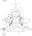
- FIG. 7 illustrates an example of an orbital forging device disclosed in JP2013-091067(A ), the orbital forging device comprising a connected body 23 of a spherical seat with shaft 12 and a molding die 15.
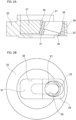
- the spherical seat with shaft 12 comprises a swinging shaft 13 and a convex spherical seat 14 that is integrally formed so as to be coaxial with the swinging shaft 13 at the end section on one side in the axial direction (lower end portion in FIG. 7 ) of the swinging shaft 13.
- the molding die 15 is held and fixed to so as to be coaxial with the swinging shaft 13.
- the other side section in the axial direction of the swinging shaft 13 of the convex spherical seat 14 (upper side portion in FIG. 7 ) spherically engages with the concave spherical seat 16 that is fixed to the frame of the orbital forging device.
- the end section on the other side in the axial direction of the swinging shaft 13 of the spherical seat with shaft 12 is connected to a driving mechanism that is assembled in the frame of the orbital forging device via a rolling bearing 28 of this driving mechanism. Further, a thrust sliding bearing 42 having a partially spherical sliding surface is assembled between the intermediate section in the axial direction of the swinging shaft 13 and the frame (concave spherical seat 16).
- driving force for swinging and rotating the spherical seat with shaft 12 and the molding die 15 is given from the driving mechanism to the end section on the other side in the axial direction of the swinging shaft 13. Further, due to the spherical engagement between the convex spherical seat 14 and the concave spherical seat 16, swing and rotation of the spherical seat with shaft 12 and the molding die 15 are allowed and processing reaction force applied to molding die 15 is supported.
- swing and rotation of the spherical seat with shaft 12 and the molding die 15 is allowed by the thrust sliding bearing 42, and the spherical seat with shaft 12 and the molding die 15 are prevented from moving to the one side in the axial direction of the swinging shaft 13 with respect to the frame (the driving mechanism and the concave spherical seat 16), that is, dropping from the orbital forging device.
- the connecting section between the end section on the other side in the axial direction of the swinging shaft 13 and the driving mechanism does not have a function that prevents the spherical seat with shaft 12 and the molding die 15 from moving to the one side in the axial direction of the swinging shaft 13 with respect to the frame (the driving mechanism and the concave spherical seat 16), instead the thrust sliding bearing 42 has this function.
- a thrust sliding bearing 42 having a partially spherical sliding surface is assembled between the intermediate section in the axial direction of the swinging shaft 13 and the frame (concave spherical seat 16). Therefore, it is required to secure installation space for this thrust sliding bearing 42 and thus the size of the orbital forging device becomes larger. Further, the partially spherical sliding surface of the thrust sliding bearing 42 is required to be formed highly precisely, so the cost for manufacturing an orbital forging device becomes higher.
- the swing angle of the molding die 15 (inclination angle ⁇ of the center axis ⁇ of the molding die 15 with respect to the center axis ⁇ of the hub body 6) is thought to be preferable to be set at 15 degrees or more and 30 degrees or less from the view point of suppressing deformation of the inner ring 7 when forming the crimped portion 9 and suppressing the maximum machining load at low level so as to make the size of the orbital forging device smaller (see JP2015-077616(A )).
- the swing angle ⁇ of the molding die 15 is set to be 15 degrees or more, the outer diameter dimension of the thrust sliding bearing 42 becomes larger as well, so problems such as increasing in size and manufacturing cost become remarkable.
- the object of the present invention is to provide construction which is able to set the swing angle of the molding die to be large at 15 degrees or more and 30 degrees or less and to reduce size of an orbital forging device as well as its manufacturing cost for the orbital forging device comprising a spherical seat with shaft that swings and rotates with a molding die.
- the orbital forging device of the present invention comprises the features of claim 1
- the rolling bearing can comprise an outer ring, an inner ring, and a plurality of rolling elements located between the outer ring and the inner ring, and is able to support axial load that acts on between the outer ring and the inner ring, and the inner ring is externally fitted onto the end section on the other side in the axial direction of the swinging shaft in a state where a displacement thereof to the other side in the axial direction of the swinging shaft is prevented, and the outer ring is fitted inside the retention hole in a state where a displacement thereof to the one side in the axial direction of the swinging shaft is prevented.
- the inclination angle of the center axis of swinging shaft with respect to the reference axis can be 15 degrees or more and 30 degrees or less.
- the method for orbital forging of the present invention is defined in appended claim 5, wherein the inclination angle of the center axis of the molding die with respect to the center axis of the shaft member can be set to be 15 degrees or more and 30 degrees or less as defined by appended claim 6.
- the end section on the other side in the axial direction of the swinging shaft is supported to the driving mechanism in a state where the movement thereof toward the one side in the axial direction is prevented. Therefore, due to this supporting section, the connected body of the swinging shaft, the convex spherical seat, and the molding die is prevented from moving toward the one side in the axial direction with respect to the frame.
- a member for preventing the swinging shaft from moving toward the one side in the axial direction with respect to the frame for example, a thrust sliding bearing having a partially spherical sliding surface, is not assembled in a section of the swinging shaft that is located between the convex spherical seat and the driving mechanism with respect to the axial direction.
- the swing angle of the molding die which is an inclination angle of the swinging shaft with respect to the reference axis can be set to be large at 15 degrees or more and 30 degrees or less, and it is possible to reduce the size of the device and its manufacturing cost.
- the rotating body of the driving mechanism comprises a case member, and a bearing holder (or a bearing holder and a holding member) which is (are) detachably fixed to the case member, by changing the inclination angle of the retention hole with respect to the reference axis by exchanging the bearing holder (or the bearing holder and the holding member), so that it is possible to change the swing angle of the molding die, which is an inclination angle of the swinging shaft with respect to the reference axis, in a wide range.
- a method for manufacturing a hub unit bearing and in a method for manufacturing a vehicle including a process of manufacturing a hub unit bearing using this method for manufacturing a hub unit bearing by employing the orbital forging device and the method for orbital forging of the present invention, it is made possible to manufacture a hub unit in which the deformation of the inner ring is suppressed and to make the device compact and reduce manufacturing cost thereof.
- the orbital forging device of the present example is used for forming a crimped portion 9 of the hub unit bearing illustrated in FIG. 4 or FIG. 5 .
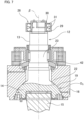
- This orbital forging device comprises a frame 10, an elevating base 11, a spherical seat with shaft 12 (provided with a swinging shaft 13 and a convex spherical seat 14), a molding die 15, a concave spherical seat 16, and a driving mechanism 17.
- the frame 10 is placed on a floor of a factory and the like.
- the frame 10 has a reference axis ⁇ in the vertical direction.
- the reference axis ⁇ is set in the vertical direction of the frame 10.
- the elevating base 11 is located at the lower section in the frame 10 so as to be able to move up and down along the reference axis ⁇ .
- a hydraulic mechanism (not shown) for driving this elevating base 11 up and down is connected to the elevating base 11.
- a support jig 18 for supporting the hub body 6, which is a work piece, without rattle in relation to the radial direction is provided at the top surface of the elevating base 11.
- the spherical seat with shaft 12 comprises a swinging shaft 13 which has a center axis ⁇ and extends along the center axis ⁇ , and a convex spherical seat 14 which is connected to the swinging shaft 13 so as to be coaxial with the swinging shaft 13 at the end section on one side in the axial direction (the lower end section in FIG. 1 ).
- the spherical seat with shaft 12 is arranged above the elevating base 11 in the frame in a state where the center axis ⁇ is tilted at a predetermined angle ⁇ to the reference axis ⁇ .
- the convex spherical seat 14 is connected to the swinging shaft 13 on the other side section in the axial direction (the upper side section in FIG.
- the other side section in the axial direction of the swinging shaft 13 of the convex spherical seat 14 is, except for the section which is connected to the swinging shaft 13 of the convex spherical seat 14, composed of a convex spherical surface section 19.
- the center of curvature of the convex spherical surface section 19 exists on the center axis ⁇ of the swinging shaft 13. Therefore, the swinging shaft 13 and the convex spherical seat 14 are arranged coaxially.
- Such spherical seat with shaft 12 may be formed so as to be integral as a whole, or formed by combining plural parts.
- the molding die 15 is connected to one side section of the convex spherical seat 14 in the axial direction of the swinging shaft 13 so as to be coaxial with the swinging shaft 13.
- the side surface of the molding die 15 on one side with relation to the axial direction of the swinging shaft 13 comprises a machining surface section 20 which is annular and coaxial with the center axis ⁇ of the swinging shaft 13.
- Such molding die 15 may be formed so as to be separate from the spherical seat with shaft 12, or may be formed so as to be integral with the entire spherical seat with shaft 12 or to be integral with some parts of the spherical seat with shaft 12.
- the concave spherical seat 16 is fixed to the intermediate section in the vertical direction of the frame 10.
- This concave spherical seat 16 comprises a concave spherical surface section 22 that spherically engages with the convex spherical surface section 19 of the convex spherical seat 14 and an insertion hole 21 to which the end section on the one side in the axial direction of the swinging shaft 13 is inserted.
- the center of curvature of the concave spherical surface section 22 exists on the reference axis ⁇ .
- Such concave spherical seat 16 allows the connected body 23 of the molding die 15 and the spherical seat with shaft 12 swing and rotate (i.e.
- the insertion hole 21 of the concave spherical seat 16 is composed of a tapered hole having an inner diameter dimension that becomes larger toward the above. Further, a portion of the inner circumferential surface of the frame 10 which is adjacent above the insertion hole 21 of the concave spherical seat 16 and to which the intermediate section in the axial direction of the swinging shaft 13 is inserted, is composed of a stepped hole 24 having an inner diameter dimension that becomes larger step by step toward the above.
- the inner diameter dimension of these insertion hole 21 and the stepped hole 24 is, as described above, set to be as small as possible within a range that the connected body 23 of the molding die 15 and the spherical seat with shaft 12 does not interfere with the swinging shaft 13 when the connected body 23 swings and rotates around the reference axis ⁇ .
- the reason why the portion of the inner circumferential surface of the frame 10 which is adjacent above the insertion hole 21 is made as the stepped hole 24 is due to easiness of processing when using general processing equipment.
- the stepped hole 24 may be changed to a tapered hole having an inner diameter dimension that becomes larger toward the above.
- the driving mechanism 17 is assembled in the upper end section in the frame 10.
- the end section on the other side in the axial direction of the swinging shaft 13 that protrudes upwards from the stepped hole 24 is connected to the driving mechanism 17.
- the driving mechanism 17 gives driving force to the end section on the other side in the axial direction of the swinging shaft 13 so as to make the connected body 23 of the molding die 15 and the spherical seat with shaft 12 swing and rotate around the reference axis ⁇ .
- the driving mechanism 17 comprises a rotating body 26, a retention hole 27, and a rolling bearing 28.
- the rotating body 26 is supported inside the upper end section of the frame 10 by a bearing device 25 so as to be able to rotate only around the reference axis ⁇ .
- An output section of a motor (not shown) for rotating and driving the rotating body 26 is connected directly or via a reducer (not shown).
- the retention hole 27 is provided in a part in the circumferential direction of the intermediate section in the radial direction of the rotating body 26.
- the center axis of the retention hole 27 is inclined by substantially the same angle as the inclination angle ⁇ with respect to the reference axis ⁇ .
- the rolling bearing 28 is arranged between the inner circumferential surface of the retention hole 27 and the outer circumferential surface of the end section on the other side in the axial direction of the swinging shaft 13, and supports the end section on the other side in the axial direction of the swinging shaft 13 with respect to the retention hole 27 so as to be able to rotate freely.
- the end section on the other side in the axial direction of the swinging shaft 13 is supported to the driving mechanism 17 in a state where the movement toward the one side in the axial direction (drop downward in FIG. 1 ).
- the rolling bearing 28 comprises construction having bearing capacity for axial load in addition to bearing capacity for radial load.
- a self-aligning roller bearing is used as the rolling bearing 28 as the rolling bearing 28, as the rolling bearing 28, a self-aligning roller bearing.
- a plurality of spherical rollers 31 are rollingly arranged between the inner circumferential surface of the outer ring 29 and the outer circumferential surface of the inner ring 30, and the attitude and the locations of these plurality of spherical rollers 31 are controlled by a cage (not shown).
- the rolling bearing 28 can support the radial load that acts on between the outer ring 29 and the inner ring 30 as well as the axial load that acts on between the outer ring 29 and the inner ring 30. Further, even if the center axes of the outer ring 29 and the inner ring 30 are slightly inclined to each other, the rolling bearing 28 has automatic alignment such as to be able to make the rolling of the spherical rollers 31 between the outer ring 29 and the inner ring 30 smooth. Specific construction of such a self-aligning roller bearing is already known, so its explanation is omitted. When embodying the present invention, as the rolling bearing 28, it is possible to use bearings such as a deep groove ball bearings and an angular ball bearing.
- the outer ring 29 is fitted inside the retention hole 27 in a state where it is prevented to move toward the one side in the axial direction of the swinging shaft 13.
- the inner circumferential surface of the retention hole 27 is composed of a stepped hole having a stepped surface 32 facing toward the other side in the axial direction (the upper side in FIG. 1 ) in the intermediate section in the axial direction.
- the outer ring 29 is fitted inside a section of the retention hole 27 which locates on the other side in the axial direction than the stepped surface 32 without rattle, and the end surface on the one side in the axial direction of the outer ring 29 comes in contact with the stepped surface 32.
- the inner ring 30 is externally fitted onto the end section on the other side in the axial direction of the swinging shaft 13 in a state where it is prevented to move toward the other side in the axial direction of the swinging shaft 13. Therefore, the inner ring 30 is externally fitted onto the end section on the other side in the axial direction of the swinging shaft 13 without rattle, and a nut 34 is screwed and fixed to a male screw section 33 which is provided at the end section on the other side in the axial direction of the swinging shaft 13, and this nut 34 comes in contact with the end surface on the other side in the axial direction of the inner ring 30.
- the size of the gap (engagement allowance) which exists in the spherical engagement section between the convex spherical surface section 19 and the concave spherical surface section 22 is optimized.
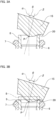
- the rotating body 26 comprises a case member 35, and a bearing holder 36, and a holding member 37 that are detachably fixed to the case member 35.
- the case member 35 constitutes the lower section of the rotating body 26, has a thick disc shape, and is arranged so as to be coaxial with the reference axis ⁇ .
- the case member 35 has a bottomed holding recess section 38 which is open to the upper side surface which is the surface opposite to the molding die 15.
- the shape of the holding recess section 38 as seen from above is rectangular which extends in the radial direction about the reference axis ⁇ .
- the case member 35 has a through-hole 39 in a part of a section which corresponds to a bottom section of the holding recess section 38. This through-hole 39 is also provided in a state it extends in the same direction as the extending direction of the holding recess section 38.
- the bearing holder 36 is fitted inside one side half section in the longitudinal direction (right half section in FIG. 2 ) without rattle.
- the holding member 37 is fitted inside the other half section in the longitudinal direction of the holding recess section 38 (left half section in FIG. 2 ) without rattle.
- the bearing holder 36 has an approximately square cylinder shape, and a retention hole 27 is provided inside the radial direction thereof.
- the first inclined surface section 40 is provided at the end section on the other side (left side in FIG. 2(a) ) in the longitudinal direction of the holding recess section 38 on the outer circumferential surface of the bearing holder 36.
- the first inclined surface section 40 is inclined in a direction toward the retention hole 27 in relation to the direction which is orthogonal to the reference axis ⁇ (the left-right direction in FIG. 2(a) ) toward the side opposite to the molding die 15 (the upper side in FIG. 2(a) in relation to direction of the reference axis ⁇ (the up-down direction in FIG. 2(a) ).
- the first inclined surface section 40 is inclined in the same direction at the same angle as the retention hole 27.
- the holding member 37 has an approximately rectangular parallelepiped shape, and the second inclined surface section 41 is provided at the end section on the one side (the right side in FIG. 2(a) ) in relation to the longitudinal direction of the holding recess section 38 on the outer circumferential surface of the holding member 47.
- the second inclined surface section 41 is inclined in the same direction at the same angle as the first inclined surface section 40.
- preload in the direction toward the bottom section side (the lower side in FIG. 2(a) ) of the holding recess section38 is applied to the holding member 37 due to tightening force of a holding bolt (not shown). Due to this, wedge effect occurs at the engagement section between the first inclined surface section 40 and the second inclined surface section 41 so that strict location control of the bearing holder 36 with respect to the holding recess section 38 is done. Further, in this state, axial force is applied to the holding bolt due to elastic deformation of the holding member 37 so that occurrence of loosening of the holding bolt by the vibration that occurs when performing orbital forging is effectively prevented.
- the bearing holder 36 and the holding member 37 are detachably fixed to the case member 35 based on attachment and detachment of the holding bolt or the lid member or the like as described above.
- the end section on the other side in the axial direction of the swinging shaft 13 is inserted into the retention hole 27 of the bearing holder 36 through the through-hole 39 of the case member 35.
- a member which prevents the swinging shaft 13 from moving toward the one side in the axial direction with respect to the frame that is, which prevents the connected body 23 of the molding die 15 and the spherical seat with shaft 12 from moving toward the one side in the axial direction of the swinging shaft 13 with respect to the frame, for example, a thrust sliding bearing having a partially spherical sliding surface, is not assembled in a portion of the swinging shaft 13 which is located between the convex spherical seat 14 and the driving mechanism 17 in the axial direction.
- the inclination angle ⁇ which is a swing angle of the molding die 15 when performing orbital forging, is set to be 15 degrees or more and 30 degrees or less.
- space for placing a member such as a thrust sliding bearing in the frame 10 is not required, because a mechanism for preventing the swinging shaft 13 from moving toward the one side in the axial direction with respect to the frame 10 is provided at the connecting section of the driving mechanism 17 and the other end section in the axial direction of the swinging shaft 13. Accordingly, reduction in size of the device and its manufacturing cost is achieved.
- the elevating base 11 is lifted in this state, and as illustrated in FIG. 3(a) , a part in the circumferential direction of the machining surface section 20 of the molding die 15 is pressed down to a part in the circumferential direction of the inner end section in the axial direction of the cylindrical section 8 which is provided at the inner end section in the axial direction of the hub body 6.
- the rotating body 26 is made rotate around the reference axis ⁇
- the connected body 23 of the molding die 15 and the spherical seat with shaft 12 is made swing and rotate around the reference axis ⁇ , that is, based on the intersection point P of the reference axis ⁇ and the center axis ⁇ of the connected body 23.
- a proximity sensor (not shown) to the orbital forging device and measure the distance between the part in the circumferential direction of the machining surface section 20 of the molding die and the part in the circumferential direction at the inner end section in the axial direction of the cylindrical section 8 which is provided at the inner end section in the axial direction of the hub body 6 by the proximity sensor, and at a stage of reaching a predetermined distance, that is, in a state where the molding die 15 and the cylindrical section 8 approach to each other but before in complete contact, initiate swinging and rotation of the connected body 23.
- the swing angle of the molding die 15 (inclination angle ⁇ ) when forming the crimped portion 9 is set to be 15 degrees or more and 30 degrees or less, it is possible to suppress the maximum machining load when performing this orbital forging.
- the inclination angle ⁇ it is also possible to set the inclination angle ⁇ to be at an angle which is not within the range of 15 degrees or more and 30 degrees or less.
- this inclination angle ⁇ is preferably at a constant angle during the process of orbital forging.
- the inclination angle ⁇ is set to be 15 degrees or more and 30 degrees or less and initiate orbital forging using the proximity sensor, and by maintaining the inclination angle ⁇ during the process of orbital forging at a constant angle, it is possible to suppress machining load for forming the crimped portion 9 and make the inner ring7 prevent the inner ring raceway 4b on the inside in the axial direction which is provided on the outer circumferential surface from plastically deforming as it bulges.
- the end section on the other side in the axial direction of the swinging shaft 13 is supported to the driving mechanism 17 in a state where the movement toward the one side in the axial direction is prevented. Therefore, due to this supporting section, it is prevented that the connected body 23 of the molding die 15 and the spherical seat with shaft 12 move toward the one side in the axial direction of the swinging shaft 13 with respect to the frame 10 (drop downwards in FIG. 1 ).
- a member for preventing the swinging shaft 13 from moving toward the one side in the axial direction with respect to the frame 10, for example, a thrust sliding bearing having a partially spherical sliding surface, is not assembled in a portion of the swinging shaft 13 which is located between the convex spherical seat 14 and the driving mechanism 17 in the axial direction. Therefore, it is possible to reduce the size and manufacturing cost of the orbital forging device by that amount.
- the bearing holder 36 and the holding member 37 are detachably fixed to the case member 35. Therefore, by changing the bearing holder 36 and the holding member 37 to change the inclination angle of the retention hole 27, it is possible to change the swing angle of the molding die 15 (inclination angle ⁇ ) in a wide range. Therefore, it is possible to select an optimal swing angle ⁇ in accordance with the type of a work piece (for example, hub body 6).
- the insertion position of the swinging shaft 13 with respect to the through-hole 39 of the case member 35 changes according to the swing angle of the molding die 15 (inclination angle ⁇ ).
Landscapes
- Engineering & Computer Science (AREA)
- Mechanical Engineering (AREA)
- General Engineering & Computer Science (AREA)
- Forging (AREA)
- Rolling Contact Bearings (AREA)
- Mounting Of Bearings Or Others (AREA)
Claims (8)
- Taumelschmiedevorrichtung, die umfasst:einen Rahmen (10) mit einer Bezugsachse (α),eine Schwenkwelle (13) mit einer Mittelachse (β), einem Endabschnitt an einer Seite in ihrer axialen Richtung und einem Endabschnitt an der anderen Seite in der axialen Richtung, wobei die Mittelachse so angeordnet ist, dass sie in Bezug auf die Bezugsachse (α) geneigt ist,eine konvexe kugelförmige Aufnahme (14) mit einem Seitenabschnitt in der axialen Richtung der Schwenkwelle (13), dem anderen Seitenabschnitt in der axialen Richtung der Schwenkwelle (13) und einem konvexen kugelförmigen Flächenabschnitt (19), der an dem anderen Seitenabschnitt vorhanden ist, wobei die konvexe kugelförmige Aufnahme (14) mit dem Endabschnitt an der einen Seite in der axialen Richtung der Schwenkwelle (13) verbunden und koaxial zu der Schwenkwelle (13) ist,ein Formwerkzeug (15), das einen Bearbeitungsflächenabschnitt (20) an einer Seitenfläche an der einen Seite in der axialen Richtung der Schwenkwelle (13) umfasst, wobei das Formwerkzeug (15) mit der Seitenfläche an der einen Seite der konvexen kugelförmigen Aufnahme (14) so verbunden ist, dass sie koaxial zu der Schwenkwelle (13) ist,eine konkave kugelförmige Aufnahme (16), die an dem Rahmen (10) befestigt ist und einen konkaven, kugelförmigen Flächenabschnitt (22), der in Kugel-Eingriff mit dem konvexen kugelförmigen Flächenabschnitt (19) ist, sowie ein Einführungsloch (21) umfasst, in das die Schwenkwelle (13) eingeführt ist, undeinen Antriebsmechanismus (17), der in den Rahmen (10) eingebaut und mit dem Endabschnitt an der anderen Seite in der axialen Richtung der Schwenkwelle (13) verbunden ist, um Antriebskraft für den Endabschnitt an der anderen Seite in der axialen Richtung der Schwenkwelle (13) bereitzustellen und einen verbundenen Körper (23) der Schwenkwelle (13), die konvexe kugelförmige Aufnahme (14) sowie das Formwerkzeug (15) um die Bezugsachse (α) herum zu drehen, wobeider Antriebsmechanismus (17) einen Drehkörper (26), der an dem Rahmen (10) um die Bezugsachse (α) herum drehbar gelagert ist, ein Rückhalteloch (27), das in dem Drehkörper (26) vorhanden ist und in das der Endabschnitt an der anderen Seite in der axialen Richtung der Schwenkwelle (13) eingeführt ist, sowie ein Wälzlager (28) umfasst, das zwischen dem Rückhalteloch (27) und dem Endabschnitt an der anderen Seite in der axialen Richtung der Schwenkwelle (13) vorhanden ist,der Endabschnitt an der anderen Seite in der axialen Richtung der Schwenkwelle (13) über das Wälzlager (28) an dem Drehkörper (26) in einem Zustand gelagert ist, in dem eine Bewegung der Schwenkwelle (13) zu der einen Seite in der axialen Richtung hin verhindert wird,der Drehkörper (26) ein Gehäuseelement (35), das an dem Rahmen (10) gelagert ist und sich um die Bezugsachse (α) dreht, sowie einen Lagerhalter (36), mit dem Rückhalteloch (27) aufweist, wobei der Lagerhalter (36) abnehmbar an dem Gehäuseelement (35) befestigt ist,das Gehäuseelement (35) eine mit Boden versehene Aufnahmeaussparung (38), die zu einer Seitenfläche desselben offen ist, die dem Formwerkzeug (15) in Bezug auf die Richtung der Bezugsachse (α) gegenüberliegt, sowie ein Durchgangsloch (39) umfasst, das in einem Teil eines Abschnitts vorhanden ist, der einem Bodenabschnitt der Aufnahmeaussparung (38) entspricht, wobei der Endabschnitt an der anderen Seite in der axialen Richtung der Schwenkwelle (13) in das Durchgangsloch (39) des Gehäuseelementes (35) und das Rückhalteloch (27) des Lagerhalters (36) eingeführt ist,dadurch gekennzeichnet, dassder Drehkörper (26) ein Halteelement (37) aufweist, das abnehmbar an dem Gehäuseelement (35) befestigt ist,der Lagerhalter (36) eine Außenumfangsfläche und einen ersten geneigten Flächenabschnitt (40) aufweist, der in einem Teil in der Umfangsrichtung der Außenumfangsfläche ausgebildet ist, wobei die erste geneigte Fläche (40) in einer Richtung auf das Rückhalteloch (27) zu in Bezug auf eine Richtung, die senkrecht zu der Bezugsachse (α) ist, zu einer gegenüberliegenden Seite des Formwerkzeugs (15) hin in Bezug auf die Richtung der Bezugsachse (α) geneigt ist,das Halteelement (37) eine Außenumfangsfläche und einen zweiten geneigten Flächenabschnitt (41) aufweist, der in einem Teil in der Umfangsrichtung der Außenumfangsfläche ausgebildet ist, wobei der zweite geneigte Flächenabschnitt (40) in der Lage ist, in einen Flächenkontakt mit dem ersten geneigten Flächenabschnitt (40) zu kommen, undder Lagerhalter (36) sowie das Halteelement (37) in das Innere der Aufnahmeaussparung (38) in einem Zustand eingepasst sind, in dem der erste geneigte Flächenabschnitt (40) und der zweite geneigte Flächenabschnitt (41) in Kontakt kommen, und Vorspannung in einer Richtung zu der Unterseite der Aufnahmeaussparung (38) hin auf das Halteelement (37) ausgeübt wird.
- Taumelschmiedevorrichtung nach Anspruch 1, wobei der Neigungswinkel der Mittelachse (β) der Schwenkwelle (13) in Bezug auf die Bezugsachse (α) 15° oder mehr und 30° oder weniger beträgt.
- Taumelschmiedevorrichtung nach Anspruch 1 oder 2, wobeidas Wälzlager (28) einen Außenring (29), einen Innenring (30) sowie eine Vielzahl von Wälzkörpern (31) umfasst, die zwischen dem Außenring (29) und dem Innenring (30) vorhanden sind, um axiale Last aufzunehmen, die zwischen dem Außenring (29) und dem Innenring (30) wirkt, undder Innenring (30) außen auf den Endabschnitt an der anderen Seite in der axialen Richtung der Schwenkwelle (13) in einem Zustand aufgepasst ist, in dem eine Verschiebung desselben zu der anderen Seite hin in der axialen Richtung der Schwenkwelle (13) verhindert wird, und der Außenring (29) innen in das Rückhalteloch (27) in einem Zustand eingepasst ist, in dem eine Verschiebung desselben zu der einen Seite hin in der axialen Richtung der Schwenkwelle (13) verhindert wird.
- Taumelschmiedevorrichtung nach Anspruch 3, wobei
die Schwenkwelle (13) an dem Ende an ihrer anderen Seite einen Außengewindeabschnitt (33) aufweist, und eine Mutter (34) auf den Außengewindeabschnitt (33) geschraubt und daran befestigt ist und mit der Endfläche an der anderen Seite in der axialen Richtung des Innenrings (30) so in Kontakt kommt, dass die Größe eines Spalts, der in einem kugelförmigen Eingriffsabschnitt zwischen dem konvexen kugelförmigen Flächenabschnitt (19) und dem konkaven kugelförmigen Flächenabschnitt (22) vorhanden ist, durch Einstellen der Schraubposition der Mutter (34) in Bezug auf den Außengewindeabschnitt (33) eingestellt werden kann. - Verfahren zum Taumelschmieden, das einen Schritt umfasst, in dem ein zylindrischer Abschnitt (8), der in einem Endabschnitt in einer axialen Richtung eines Wellenelementes (6) vorhanden ist, nach außen in einer radialen Richtung desselben plastisch verformt wird, um einen Quetschabschnitt (9) auszubilden, dadurch gekennzeichnet, dass
unter Verwendung der Taumelschmiedevorrichtung nach einem der Ansprüche 1 bis 4 das Formwerkzeug (15) in einem Zustand, in dem die Mittelachse (β) des Formwerkzeugs (15) um einen vorgegebenen Winkel zu der Mittelachse (α) des Wellenelementes (6) geneigt ist, in der axialen Richtung des zylindrischen Abschnitts (8) des Wellenelementes (6) auf den Endabschnitt nach unten gedrückt wird. - Verfahren zum Taumelschmieden nach Anspruch 5, wobei der Neigungswinkel der Mittelachse (β) des Formwerkzeugs (15) in Bezug auf die Mittelachse (α) des Wellenelementes (6) auf 15° oder mehr und 30° oder weniger eingestellt wird.
- Verfahren zum Herstellen eines Lagers für eine Nabeneinheit, wobei das Lager für eine Nabeneinheit umfasst:einen Außenring (1), der sich In Betrieb in einem Zustand, in dem er mit einer Aufhängung verbunden und daran befestigt ist, nicht dreht, eine Nabe (2), die sich In Betrieb in einem Zustand, in dem ein Rad daran gelagert und befestigt ist, zusammen mit dem Rad dreht, undeine Vielzahl von Wälzkörpem (5), die rollend zwischen zweireihigen Außenring-Laufbahnen (3a, 3b), die an einer Innenumfangsfläche des Außenrings (1) vorhanden sind, und zweireihigen Innenring-Laufbahnen (4a, 4b) vorhanden sind, die an einer Außenumfangsfläche der Nabe (2) vorhanden sind,die Nabe (2) einen Nabenkörper (6) mit einer Innenring-Laufbahn (4a) an einer Außenseite in einer axialen Richtung der zweireihigen Innenring-Laufbahnen (4a, 4b) an einer Außenumfangsfläche derselben sowie einen Innenring (7) mit einer Innenring-Laufbahn (4b) an einer Innenseite in der axialen Richtung der zweireihigen Innenring-Laufbahn (4a, 4b) an einer Außenumfangsfläche derselben aufweist, wobei der Nabenkörper (6) und der Innenring (7) aneinander befestigt und fixiert sind, unddas Verfahren zum Herstellen des Lagers für eine Nabeneinheit einen Schritt umfasst, in dem ein innerer Endabschnitt in einer axialen Richtung eines zylindrischen Abschnitts (8), der an einem inneren Endabschnitt in einer axialen Richtung des Nabenkörpers (6) vorhanden ist, in einer radialen Richtung plastisch nach außen verformt wird, wobei der Innenring (7) unter Einsatz der Taumelschmiedevorrichtung nach einem der Ansprüche 1 bis 4 außen auf einen Abschnitt in der Nähe eines inneren Endes in der axialen Richtung des Nabenkörpers (6) aufgepasst wird, um einen Quetschabschnitt (9) auszubilden und zu veranlassen, dass der Quetschabschnitt (9) eine innere Endfläche in der axialen Richtung des Innenrings (7) nach unten drückt.
- Verfahren zum Herstellen eines Fahrzeugs,wobei das Fahrzeug eine Struktur aufweist, in der ein Rad mittels eines Lagers für eine Nabeneinheit drehbar an einer Aufhängung des Fahrzeugs gelagert ist, unddas Herstellungsverfahren einen Schritt zum Herstellen des Lagers für eine Nabeneinheit unter Einsatz des Verfahrens zum Herstellen des Lagers für eine Nabeneinheit nach Anspruch 7 umfasst.
Applications Claiming Priority (2)
| Application Number | Priority Date | Filing Date | Title |
|---|---|---|---|
| JP2017038933 | 2017-03-02 | ||
| PCT/JP2018/007486 WO2018159670A1 (ja) | 2017-03-02 | 2018-02-28 | 揺動鍛造装置、揺動鍛造方法、該揺動鍛造方法を用いたハブユニット軸受の製造方法および車両の製造方法 |
Publications (3)
| Publication Number | Publication Date |
|---|---|
| EP3590624A1 EP3590624A1 (de) | 2020-01-08 |
| EP3590624A4 EP3590624A4 (de) | 2020-07-29 |
| EP3590624B1 true EP3590624B1 (de) | 2023-06-28 |
Family
ID=63369927
Family Applications (1)
| Application Number | Title | Priority Date | Filing Date |
|---|---|---|---|
| EP18761668.5A Active EP3590624B1 (de) | 2017-03-02 | 2018-02-28 | Taumelpressvorrichtung, taumelpressverfahren, verfahren zur herstellung einer nabeneinheit mithilfe des taumelpressverfahrens und fahrzeugherstellungsverfahren |
Country Status (6)
| Country | Link |
|---|---|
| US (2) | US11103917B2 (de) |
| EP (1) | EP3590624B1 (de) |
| JP (3) | JP6566167B2 (de) |
| KR (1) | KR102522747B1 (de) |
| CN (1) | CN110290885B (de) |
| WO (1) | WO2018159670A1 (de) |
Families Citing this family (11)
| Publication number | Priority date | Publication date | Assignee | Title |
|---|---|---|---|---|
| CN111971133B (zh) | 2018-02-13 | 2022-07-19 | 日本精工株式会社 | 摆动锻造装置的动态载荷测定及校正方法、动态载荷测定装置、轮毂单元轴承和车辆的制造方法 |
| JP6940011B2 (ja) | 2019-04-10 | 2021-09-22 | 日本精工株式会社 | かしめアセンブリの製造方法、ハブユニット軸受の製造方法、かしめ装置、かしめアセンブリ、及び車両の製造方法 |
| KR102792022B1 (ko) | 2019-04-10 | 2025-04-04 | 닛본 세이고 가부시끼가이샤 | 코킹 어셈블리의 제조 방법, 허브 유닛 베어링의 제조 방법 및 차량의 제조 방법 |
| CN110918849B (zh) * | 2019-11-26 | 2020-12-22 | 武汉理工大学 | 一种提高薄壁高筋构件空间包络成形高筋成形极限的方法 |
| CN111181344B (zh) * | 2020-01-08 | 2020-11-03 | 上海交通大学 | 摆动式表面显微冷锻装置 |
| CN112916782B (zh) * | 2021-02-07 | 2023-06-20 | 哈尔滨工业大学 | 一种带有局部突变特征的超长薄腹板高筋复杂构件的局部渐进加载精密成形模具及方法 |
| CN115090814B (zh) * | 2022-07-25 | 2024-09-24 | 浙江斯凯福汽车零部件有限公司 | 一种汽车轮毂外圈的精锻成型装置及其工艺 |
| CN117072573B (zh) * | 2023-09-07 | 2026-02-27 | 山东哈临集团有限公司 | 一种自润滑关节轴承外圈衬垫压装装置 |
| CN117086251B (zh) * | 2023-10-16 | 2024-01-05 | 常州市科宇重工科技有限公司 | 一种铸锻件成型锻打装置 |
| CN117366100A (zh) * | 2023-10-24 | 2024-01-09 | 厦门威迪康科技有限公司 | 一种防静电的轴承组件与椭圆机 |
| CN117816888B (zh) * | 2023-12-12 | 2024-06-21 | 江苏珀然轮毂有限公司 | 一种高强度铝合金车轮锻造模具 |
Citations (1)
| Publication number | Priority date | Publication date | Assignee | Title |
|---|---|---|---|---|
| JPH02108537U (de) * | 1989-02-09 | 1990-08-29 |
Family Cites Families (34)
| Publication number | Priority date | Publication date | Assignee | Title |
|---|---|---|---|---|
| GB319065A (en) * | 1928-05-19 | 1929-09-19 | Massey Ltd B & S | Improvements in forging and upsetting machines |
| DE1652653B1 (de) * | 1967-01-20 | 1972-05-31 | Politechnika Warszawska | Walzgesenkpresse |
| FR1560475A (de) | 1968-01-18 | 1969-03-21 | ||
| JPS5048841U (de) * | 1973-09-04 | 1975-05-14 | ||
| SU517514A1 (ru) | 1974-07-24 | 1976-06-15 | Ижевский механический институт | Устройство дл штамповки заготовок |
| DE3202254C2 (de) * | 1982-01-25 | 1986-02-20 | Zahnradfabrik Friedrichshafen Ag, 7990 Friedrichshafen | Verfahren und Vorrichtung zum Herstellen einer Zahnstange |
| CH662983A5 (de) | 1984-04-21 | 1987-11-13 | Heinrich Schmid Maschinen Und | Taumelpresse. |
| JPH01317650A (ja) | 1988-06-20 | 1989-12-22 | Sumitomo Heavy Ind Ltd | 揺動鍛造機 |
| JPH02197345A (ja) * | 1989-01-24 | 1990-08-03 | Mitsubishi Nagasaki Kiko Kk | 回転揺動鍛造機の回転揺動軸の回転ずれ防止装置 |
| US4982589A (en) | 1989-02-14 | 1991-01-08 | Brother Kogyo Kabushiki Kaisha | Swiveling type plastic working machine |
| JPH02251330A (ja) | 1989-02-14 | 1990-10-09 | Brother Ind Ltd | 鍛造方法 |
| JPH04200947A (ja) * | 1990-11-30 | 1992-07-21 | Fuji Car Mfg Co Ltd | 揺動鍛造プレス機 |
| CN2134900Y (zh) * | 1992-09-26 | 1993-06-02 | 许德安 | 直线摆动辗压机 |
| GB9300529D0 (en) * | 1993-01-13 | 1993-03-03 | Penny & Giles Blackwood Ltd | Improvements in rotary forging |
| JPH06285576A (ja) * | 1993-04-02 | 1994-10-11 | Citizen Watch Co Ltd | 揺動鍛造パンチの製造装置及び揺動鍛造パンチの製造方法 |
| JP2000343905A (ja) | 1999-06-02 | 2000-12-12 | Nsk Ltd | 車輪支持用転がり軸受ユニットの組立方法 |
| JP2003083353A (ja) | 2001-07-03 | 2003-03-19 | Nsk Ltd | 車輪支持用転がり軸受ユニットの製造方法及び製造装置 |
| JP4852922B2 (ja) * | 2005-07-26 | 2012-01-11 | 株式会社ジェイテクト | ラック軸の製造方法 |
| CN2898424Y (zh) * | 2006-05-12 | 2007-05-09 | 朱申明 | 振动筛轴承外圈胀套式固定结构 |
| JP5261023B2 (ja) * | 2008-05-13 | 2013-08-14 | Ntn株式会社 | 車輪用軸受装置の加工方法 |
| JP2012045612A (ja) * | 2010-08-30 | 2012-03-08 | Jtekt Corp | 車両用ハブユニットの製造方法 |
| JP2012197932A (ja) * | 2011-03-07 | 2012-10-18 | Jtekt Corp | 車輪用転がり軸受装置の製造方法 |
| JP2012183562A (ja) * | 2011-03-07 | 2012-09-27 | Jtekt Corp | 車輪用転がり軸受装置の軸部材の製造方法 |
| JP5716917B2 (ja) | 2011-10-24 | 2015-05-13 | トヨタ自動車株式会社 | 揺動鍛造装置及び揺動鍛造方法 |
| US8590657B2 (en) | 2011-12-09 | 2013-11-26 | GM Global Technology Operations LLC | Vehicle wheel assembly having a self-retaining bearing |
| US9103375B2 (en) * | 2012-12-14 | 2015-08-11 | Aktiebolaget Skf | Cartridge bearing assembly |
| JP6026374B2 (ja) * | 2013-09-02 | 2016-11-16 | 住友重機械工業株式会社 | 鍛造用スイングプレス |
| JP6237100B2 (ja) | 2013-10-17 | 2017-11-29 | 日本精工株式会社 | 車輪支持用転がり軸受ユニットの製造方法 |
| CN203944773U (zh) * | 2014-06-23 | 2014-11-19 | 徐州达一锻压设备有限公司 | 摆动碾压机的球面摆头装置 |
| JP6379798B2 (ja) * | 2014-07-25 | 2018-08-29 | 日本精工株式会社 | 転がり軸受ユニットの製造方法及び車両の製造方法 |
| JP6464625B2 (ja) | 2014-09-15 | 2019-02-06 | 株式会社ジェイテクト | ハブユニット製造装置 |
| JP6197831B2 (ja) * | 2015-06-05 | 2017-09-20 | 日本精工株式会社 | 車輪支持用転がり軸受ユニットの製造方法及び自動車の製造方法 |
| JP6222177B2 (ja) * | 2015-07-13 | 2017-11-01 | 日本精工株式会社 | 転がり軸受ユニットの製造方法、車両の製造方法 |
| JP6160715B2 (ja) * | 2016-01-07 | 2017-07-12 | 日本精工株式会社 | 車輪支持用転がり軸受ユニット |
-
2018
- 2018-02-28 WO PCT/JP2018/007486 patent/WO2018159670A1/ja not_active Ceased
- 2018-02-28 KR KR1020197021474A patent/KR102522747B1/ko active Active
- 2018-02-28 EP EP18761668.5A patent/EP3590624B1/de active Active
- 2018-02-28 CN CN201880012186.9A patent/CN110290885B/zh active Active
- 2018-02-28 US US16/490,305 patent/US11103917B2/en active Active
- 2018-02-28 JP JP2019503057A patent/JP6566167B2/ja active Active
-
2019
- 2019-07-05 JP JP2019125653A patent/JP6835154B2/ja active Active
-
2020
- 2020-11-09 JP JP2020186660A patent/JP7243703B2/ja active Active
-
2021
- 2021-06-15 US US17/347,718 patent/US11904383B2/en active Active
Patent Citations (1)
| Publication number | Priority date | Publication date | Assignee | Title |
|---|---|---|---|---|
| JPH02108537U (de) * | 1989-02-09 | 1990-08-29 |
Also Published As
| Publication number | Publication date |
|---|---|
| EP3590624A4 (de) | 2020-07-29 |
| JP2019181571A (ja) | 2019-10-24 |
| CN110290885A (zh) | 2019-09-27 |
| JP7243703B2 (ja) | 2023-03-22 |
| JPWO2018159670A1 (ja) | 2019-06-27 |
| KR20190122654A (ko) | 2019-10-30 |
| WO2018159670A1 (ja) | 2018-09-07 |
| EP3590624A1 (de) | 2020-01-08 |
| JP2021013960A (ja) | 2021-02-12 |
| CN110290885B (zh) | 2023-09-19 |
| US11103917B2 (en) | 2021-08-31 |
| JP6566167B2 (ja) | 2019-08-28 |
| JP6835154B2 (ja) | 2021-02-24 |
| US20210308744A1 (en) | 2021-10-07 |
| US20200009642A1 (en) | 2020-01-09 |
| US11904383B2 (en) | 2024-02-20 |
| KR102522747B1 (ko) | 2023-04-17 |
Similar Documents
| Publication | Publication Date | Title |
|---|---|---|
| US11904383B2 (en) | Orbital forging device, method for orbital forging, method for manufacturing hub unit bearing using method for orbital forging, and method for manufacturing vehicle | |
| JP2019181571A5 (de) | ||
| JP6624354B1 (ja) | 揺動加工装置、ハブユニット軸受の製造方法および自動車の製造方法 | |
| EP2119926B1 (de) | Radlagervorrichtung und verfahren sie herzustellen | |
| JP2002283805A (ja) | 自動車用ハブユニットの組立方法 | |
| US20080194342A1 (en) | Universal Joint Socket With Axial Guiding | |
| JP2007290681A (ja) | 駆動輪支持用ハブユニットとその製造方法 | |
| US11745249B2 (en) | Rotary caulking device, method of manufacturing hub unit bearing and method of manufacturing vehicle | |
| US12123466B2 (en) | Staking apparatus and staking method for bearing unit, manufacturing method and manufacturing apparatus of hub unit bearing, and manufacturing method of vehicle | |
| JP6515774B2 (ja) | 車輪支持用複列円すいころ軸受ユニット | |
| EP4692580A1 (de) | Herstellungsverfahren für dichtanordnung, nabeneinheitslagerherstellungsverfahren, fahrzeugherstellungsverfahren, fahrzeugherstellungsausrüstung, maschinenherstellungsausrüstung, maschine und fahrzeug | |
| WO2003057512A1 (en) | Unitized wheel end | |
| JP2013010409A (ja) | 車軸用軸受装置 |
Legal Events
| Date | Code | Title | Description |
|---|---|---|---|
| STAA | Information on the status of an ep patent application or granted ep patent |
Free format text: STATUS: THE INTERNATIONAL PUBLICATION HAS BEEN MADE |
|
| PUAI | Public reference made under article 153(3) epc to a published international application that has entered the european phase |
Free format text: ORIGINAL CODE: 0009012 |
|
| STAA | Information on the status of an ep patent application or granted ep patent |
Free format text: STATUS: REQUEST FOR EXAMINATION WAS MADE |
|
| 17P | Request for examination filed |
Effective date: 20191001 |
|
| AK | Designated contracting states |
Kind code of ref document: A1 Designated state(s): AL AT BE BG CH CY CZ DE DK EE ES FI FR GB GR HR HU IE IS IT LI LT LU LV MC MK MT NL NO PL PT RO RS SE SI SK SM TR |
|
| AX | Request for extension of the european patent |
Extension state: BA ME |
|
| DAV | Request for validation of the european patent (deleted) | ||
| DAX | Request for extension of the european patent (deleted) | ||
| A4 | Supplementary search report drawn up and despatched |
Effective date: 20200701 |
|
| RIC1 | Information provided on ipc code assigned before grant |
Ipc: B21J 9/02 20060101AFI20200625BHEP Ipc: B21K 1/04 20060101ALI20200625BHEP Ipc: B21K 25/00 20060101ALI20200625BHEP Ipc: F16C 23/08 20060101ALI20200625BHEP Ipc: B21K 1/40 20060101ALI20200625BHEP |
|
| STAA | Information on the status of an ep patent application or granted ep patent |
Free format text: STATUS: EXAMINATION IS IN PROGRESS |
|
| 17Q | First examination report despatched |
Effective date: 20210621 |
|
| GRAP | Despatch of communication of intention to grant a patent |
Free format text: ORIGINAL CODE: EPIDOSNIGR1 |
|
| STAA | Information on the status of an ep patent application or granted ep patent |
Free format text: STATUS: GRANT OF PATENT IS INTENDED |
|
| INTG | Intention to grant announced |
Effective date: 20230206 |
|
| GRAS | Grant fee paid |
Free format text: ORIGINAL CODE: EPIDOSNIGR3 |
|
| GRAA | (expected) grant |
Free format text: ORIGINAL CODE: 0009210 |
|
| STAA | Information on the status of an ep patent application or granted ep patent |
Free format text: STATUS: THE PATENT HAS BEEN GRANTED |
|
| AK | Designated contracting states |
Kind code of ref document: B1 Designated state(s): AL AT BE BG CH CY CZ DE DK EE ES FI FR GB GR HR HU IE IS IT LI LT LU LV MC MK MT NL NO PL PT RO RS SE SI SK SM TR |
|
| REG | Reference to a national code |
Ref country code: CH Ref legal event code: EP |
|
| REG | Reference to a national code |
Ref country code: AT Ref legal event code: REF Ref document number: 1582247 Country of ref document: AT Kind code of ref document: T Effective date: 20230715 |
|
| REG | Reference to a national code |
Ref country code: IE Ref legal event code: FG4D |
|
| REG | Reference to a national code |
Ref country code: DE Ref legal event code: R096 Ref document number: 602018052466 Country of ref document: DE |
|
| REG | Reference to a national code |
Ref country code: LT Ref legal event code: MG9D |
|
| PG25 | Lapsed in a contracting state [announced via postgrant information from national office to epo] |
Ref country code: SE Free format text: LAPSE BECAUSE OF FAILURE TO SUBMIT A TRANSLATION OF THE DESCRIPTION OR TO PAY THE FEE WITHIN THE PRESCRIBED TIME-LIMIT Effective date: 20230628 Ref country code: NO Free format text: LAPSE BECAUSE OF FAILURE TO SUBMIT A TRANSLATION OF THE DESCRIPTION OR TO PAY THE FEE WITHIN THE PRESCRIBED TIME-LIMIT Effective date: 20230928 |
|
| REG | Reference to a national code |
Ref country code: NL Ref legal event code: MP Effective date: 20230628 |
|
| REG | Reference to a national code |
Ref country code: AT Ref legal event code: MK05 Ref document number: 1582247 Country of ref document: AT Kind code of ref document: T Effective date: 20230628 |
|
| PG25 | Lapsed in a contracting state [announced via postgrant information from national office to epo] |
Ref country code: RS Free format text: LAPSE BECAUSE OF FAILURE TO SUBMIT A TRANSLATION OF THE DESCRIPTION OR TO PAY THE FEE WITHIN THE PRESCRIBED TIME-LIMIT Effective date: 20230628 Ref country code: NL Free format text: LAPSE BECAUSE OF FAILURE TO SUBMIT A TRANSLATION OF THE DESCRIPTION OR TO PAY THE FEE WITHIN THE PRESCRIBED TIME-LIMIT Effective date: 20230628 Ref country code: LV Free format text: LAPSE BECAUSE OF FAILURE TO SUBMIT A TRANSLATION OF THE DESCRIPTION OR TO PAY THE FEE WITHIN THE PRESCRIBED TIME-LIMIT Effective date: 20230628 Ref country code: LT Free format text: LAPSE BECAUSE OF FAILURE TO SUBMIT A TRANSLATION OF THE DESCRIPTION OR TO PAY THE FEE WITHIN THE PRESCRIBED TIME-LIMIT Effective date: 20230628 Ref country code: HR Free format text: LAPSE BECAUSE OF FAILURE TO SUBMIT A TRANSLATION OF THE DESCRIPTION OR TO PAY THE FEE WITHIN THE PRESCRIBED TIME-LIMIT Effective date: 20230628 Ref country code: GR Free format text: LAPSE BECAUSE OF FAILURE TO SUBMIT A TRANSLATION OF THE DESCRIPTION OR TO PAY THE FEE WITHIN THE PRESCRIBED TIME-LIMIT Effective date: 20230929 |
|
| PG25 | Lapsed in a contracting state [announced via postgrant information from national office to epo] |
Ref country code: FI Free format text: LAPSE BECAUSE OF FAILURE TO SUBMIT A TRANSLATION OF THE DESCRIPTION OR TO PAY THE FEE WITHIN THE PRESCRIBED TIME-LIMIT Effective date: 20230628 |
|
| PG25 | Lapsed in a contracting state [announced via postgrant information from national office to epo] |
Ref country code: SK Free format text: LAPSE BECAUSE OF FAILURE TO SUBMIT A TRANSLATION OF THE DESCRIPTION OR TO PAY THE FEE WITHIN THE PRESCRIBED TIME-LIMIT Effective date: 20230628 |
|
| PG25 | Lapsed in a contracting state [announced via postgrant information from national office to epo] |
Ref country code: ES Free format text: LAPSE BECAUSE OF FAILURE TO SUBMIT A TRANSLATION OF THE DESCRIPTION OR TO PAY THE FEE WITHIN THE PRESCRIBED TIME-LIMIT Effective date: 20230628 |
|
| PG25 | Lapsed in a contracting state [announced via postgrant information from national office to epo] |
Ref country code: IS Free format text: LAPSE BECAUSE OF FAILURE TO SUBMIT A TRANSLATION OF THE DESCRIPTION OR TO PAY THE FEE WITHIN THE PRESCRIBED TIME-LIMIT Effective date: 20231028 |
|
| PG25 | Lapsed in a contracting state [announced via postgrant information from national office to epo] |
Ref country code: SM Free format text: LAPSE BECAUSE OF FAILURE TO SUBMIT A TRANSLATION OF THE DESCRIPTION OR TO PAY THE FEE WITHIN THE PRESCRIBED TIME-LIMIT Effective date: 20230628 Ref country code: SK Free format text: LAPSE BECAUSE OF FAILURE TO SUBMIT A TRANSLATION OF THE DESCRIPTION OR TO PAY THE FEE WITHIN THE PRESCRIBED TIME-LIMIT Effective date: 20230628 Ref country code: RO Free format text: LAPSE BECAUSE OF FAILURE TO SUBMIT A TRANSLATION OF THE DESCRIPTION OR TO PAY THE FEE WITHIN THE PRESCRIBED TIME-LIMIT Effective date: 20230628 Ref country code: PT Free format text: LAPSE BECAUSE OF FAILURE TO SUBMIT A TRANSLATION OF THE DESCRIPTION OR TO PAY THE FEE WITHIN THE PRESCRIBED TIME-LIMIT Effective date: 20231030 Ref country code: IS Free format text: LAPSE BECAUSE OF FAILURE TO SUBMIT A TRANSLATION OF THE DESCRIPTION OR TO PAY THE FEE WITHIN THE PRESCRIBED TIME-LIMIT Effective date: 20231028 Ref country code: ES Free format text: LAPSE BECAUSE OF FAILURE TO SUBMIT A TRANSLATION OF THE DESCRIPTION OR TO PAY THE FEE WITHIN THE PRESCRIBED TIME-LIMIT Effective date: 20230628 Ref country code: EE Free format text: LAPSE BECAUSE OF FAILURE TO SUBMIT A TRANSLATION OF THE DESCRIPTION OR TO PAY THE FEE WITHIN THE PRESCRIBED TIME-LIMIT Effective date: 20230628 Ref country code: CZ Free format text: LAPSE BECAUSE OF FAILURE TO SUBMIT A TRANSLATION OF THE DESCRIPTION OR TO PAY THE FEE WITHIN THE PRESCRIBED TIME-LIMIT Effective date: 20230628 Ref country code: AT Free format text: LAPSE BECAUSE OF FAILURE TO SUBMIT A TRANSLATION OF THE DESCRIPTION OR TO PAY THE FEE WITHIN THE PRESCRIBED TIME-LIMIT Effective date: 20230628 |
|
| PG25 | Lapsed in a contracting state [announced via postgrant information from national office to epo] |
Ref country code: PL Free format text: LAPSE BECAUSE OF FAILURE TO SUBMIT A TRANSLATION OF THE DESCRIPTION OR TO PAY THE FEE WITHIN THE PRESCRIBED TIME-LIMIT Effective date: 20230628 |
|
| REG | Reference to a national code |
Ref country code: DE Ref legal event code: R097 Ref document number: 602018052466 Country of ref document: DE |
|
| PG25 | Lapsed in a contracting state [announced via postgrant information from national office to epo] |
Ref country code: DK Free format text: LAPSE BECAUSE OF FAILURE TO SUBMIT A TRANSLATION OF THE DESCRIPTION OR TO PAY THE FEE WITHIN THE PRESCRIBED TIME-LIMIT Effective date: 20230628 |
|
| PLBE | No opposition filed within time limit |
Free format text: ORIGINAL CODE: 0009261 |
|
| STAA | Information on the status of an ep patent application or granted ep patent |
Free format text: STATUS: NO OPPOSITION FILED WITHIN TIME LIMIT |
|
| PG25 | Lapsed in a contracting state [announced via postgrant information from national office to epo] |
Ref country code: IT Free format text: LAPSE BECAUSE OF FAILURE TO SUBMIT A TRANSLATION OF THE DESCRIPTION OR TO PAY THE FEE WITHIN THE PRESCRIBED TIME-LIMIT Effective date: 20230628 |
|
| 26N | No opposition filed |
Effective date: 20240402 |
|
| PG25 | Lapsed in a contracting state [announced via postgrant information from national office to epo] |
Ref country code: SI Free format text: LAPSE BECAUSE OF FAILURE TO SUBMIT A TRANSLATION OF THE DESCRIPTION OR TO PAY THE FEE WITHIN THE PRESCRIBED TIME-LIMIT Effective date: 20230628 |
|
| PG25 | Lapsed in a contracting state [announced via postgrant information from national office to epo] |
Ref country code: MC Free format text: LAPSE BECAUSE OF FAILURE TO SUBMIT A TRANSLATION OF THE DESCRIPTION OR TO PAY THE FEE WITHIN THE PRESCRIBED TIME-LIMIT Effective date: 20230628 |
|
| REG | Reference to a national code |
Ref country code: CH Ref legal event code: PL |
|
| PG25 | Lapsed in a contracting state [announced via postgrant information from national office to epo] |
Ref country code: LU Free format text: LAPSE BECAUSE OF NON-PAYMENT OF DUE FEES Effective date: 20240228 |
|
| PG25 | Lapsed in a contracting state [announced via postgrant information from national office to epo] |
Ref country code: CH Free format text: LAPSE BECAUSE OF NON-PAYMENT OF DUE FEES Effective date: 20240229 |
|
| PG25 | Lapsed in a contracting state [announced via postgrant information from national office to epo] |
Ref country code: LU Free format text: LAPSE BECAUSE OF NON-PAYMENT OF DUE FEES Effective date: 20240228 Ref country code: CH Free format text: LAPSE BECAUSE OF NON-PAYMENT OF DUE FEES Effective date: 20240229 |
|
| PG25 | Lapsed in a contracting state [announced via postgrant information from national office to epo] |
Ref country code: BG Free format text: LAPSE BECAUSE OF FAILURE TO SUBMIT A TRANSLATION OF THE DESCRIPTION OR TO PAY THE FEE WITHIN THE PRESCRIBED TIME-LIMIT Effective date: 20230628 |
|
| PG25 | Lapsed in a contracting state [announced via postgrant information from national office to epo] |
Ref country code: BG Free format text: LAPSE BECAUSE OF FAILURE TO SUBMIT A TRANSLATION OF THE DESCRIPTION OR TO PAY THE FEE WITHIN THE PRESCRIBED TIME-LIMIT Effective date: 20230628 |
|
| REG | Reference to a national code |
Ref country code: BE Ref legal event code: MM Effective date: 20240229 |
|
| PG25 | Lapsed in a contracting state [announced via postgrant information from national office to epo] |
Ref country code: BE Free format text: LAPSE BECAUSE OF NON-PAYMENT OF DUE FEES Effective date: 20240229 |
|
| PG25 | Lapsed in a contracting state [announced via postgrant information from national office to epo] |
Ref country code: IE Free format text: LAPSE BECAUSE OF NON-PAYMENT OF DUE FEES Effective date: 20240228 |
|
| PG25 | Lapsed in a contracting state [announced via postgrant information from national office to epo] |
Ref country code: IE Free format text: LAPSE BECAUSE OF NON-PAYMENT OF DUE FEES Effective date: 20240228 Ref country code: BE Free format text: LAPSE BECAUSE OF NON-PAYMENT OF DUE FEES Effective date: 20240229 |
|
| PGFP | Annual fee paid to national office [announced via postgrant information from national office to epo] |
Ref country code: DE Payment date: 20241231 Year of fee payment: 8 |
|
| PGFP | Annual fee paid to national office [announced via postgrant information from national office to epo] |
Ref country code: GB Payment date: 20250102 Year of fee payment: 8 |
|
| PG25 | Lapsed in a contracting state [announced via postgrant information from national office to epo] |
Ref country code: CY Free format text: LAPSE BECAUSE OF FAILURE TO SUBMIT A TRANSLATION OF THE DESCRIPTION OR TO PAY THE FEE WITHIN THE PRESCRIBED TIME-LIMIT; INVALID AB INITIO Effective date: 20180228 |
|
| PG25 | Lapsed in a contracting state [announced via postgrant information from national office to epo] |
Ref country code: HU Free format text: LAPSE BECAUSE OF FAILURE TO SUBMIT A TRANSLATION OF THE DESCRIPTION OR TO PAY THE FEE WITHIN THE PRESCRIBED TIME-LIMIT; INVALID AB INITIO Effective date: 20180228 |
|
| PG25 | Lapsed in a contracting state [announced via postgrant information from national office to epo] |
Ref country code: TR Free format text: LAPSE BECAUSE OF FAILURE TO SUBMIT A TRANSLATION OF THE DESCRIPTION OR TO PAY THE FEE WITHIN THE PRESCRIBED TIME-LIMIT Effective date: 20230628 |
|
| PGFP | Annual fee paid to national office [announced via postgrant information from national office to epo] |
Ref country code: FR Payment date: 20251231 Year of fee payment: 9 |