WO2017010481A1 - 軸受ユニットの製造方法及び製造装置 - Google Patents
軸受ユニットの製造方法及び製造装置 Download PDFInfo
- Publication number
- WO2017010481A1 WO2017010481A1 PCT/JP2016/070551 JP2016070551W WO2017010481A1 WO 2017010481 A1 WO2017010481 A1 WO 2017010481A1 JP 2016070551 W JP2016070551 W JP 2016070551W WO 2017010481 A1 WO2017010481 A1 WO 2017010481A1
- Authority
- WO
- WIPO (PCT)
- Prior art keywords
- hub
- end surface
- axial direction
- axial
- central axis
- Prior art date
Links
Images


Classifications
-
- F—MECHANICAL ENGINEERING; LIGHTING; HEATING; WEAPONS; BLASTING
- F16—ENGINEERING ELEMENTS AND UNITS; GENERAL MEASURES FOR PRODUCING AND MAINTAINING EFFECTIVE FUNCTIONING OF MACHINES OR INSTALLATIONS; THERMAL INSULATION IN GENERAL
- F16C—SHAFTS; FLEXIBLE SHAFTS; ELEMENTS OR CRANKSHAFT MECHANISMS; ROTARY BODIES OTHER THAN GEARING ELEMENTS; BEARINGS
- F16C43/00—Assembling bearings
- F16C43/04—Assembling rolling-contact bearings
- F16C43/06—Placing rolling bodies in cages or bearings
- F16C43/08—Placing rolling bodies in cages or bearings by deforming the cages or the races
-
- B—PERFORMING OPERATIONS; TRANSPORTING
- B21—MECHANICAL METAL-WORKING WITHOUT ESSENTIALLY REMOVING MATERIAL; PUNCHING METAL
- B21D—WORKING OR PROCESSING OF SHEET METAL OR METAL TUBES, RODS OR PROFILES WITHOUT ESSENTIALLY REMOVING MATERIAL; PUNCHING METAL
- B21D39/00—Application of procedures in order to connect objects or parts, e.g. coating with sheet metal otherwise than by plating; Tube expanders
- B21D39/02—Application of procedures in order to connect objects or parts, e.g. coating with sheet metal otherwise than by plating; Tube expanders of sheet metal by folding, e.g. connecting edges of a sheet to form a cylinder
- B21D39/021—Application of procedures in order to connect objects or parts, e.g. coating with sheet metal otherwise than by plating; Tube expanders of sheet metal by folding, e.g. connecting edges of a sheet to form a cylinder for panels, e.g. vehicle doors
- B21D39/023—Application of procedures in order to connect objects or parts, e.g. coating with sheet metal otherwise than by plating; Tube expanders of sheet metal by folding, e.g. connecting edges of a sheet to form a cylinder for panels, e.g. vehicle doors using rollers
-
- B—PERFORMING OPERATIONS; TRANSPORTING
- B21—MECHANICAL METAL-WORKING WITHOUT ESSENTIALLY REMOVING MATERIAL; PUNCHING METAL
- B21J—FORGING; HAMMERING; PRESSING METAL; RIVETING; FORGE FURNACES
- B21J5/00—Methods for forging, hammering, or pressing; Special equipment or accessories therefor
- B21J5/06—Methods for forging, hammering, or pressing; Special equipment or accessories therefor for performing particular operations
- B21J5/12—Forming profiles on internal or external surfaces
-
- B—PERFORMING OPERATIONS; TRANSPORTING
- B21—MECHANICAL METAL-WORKING WITHOUT ESSENTIALLY REMOVING MATERIAL; PUNCHING METAL
- B21J—FORGING; HAMMERING; PRESSING METAL; RIVETING; FORGE FURNACES
- B21J9/00—Forging presses
- B21J9/02—Special design or construction
-
- B—PERFORMING OPERATIONS; TRANSPORTING
- B21—MECHANICAL METAL-WORKING WITHOUT ESSENTIALLY REMOVING MATERIAL; PUNCHING METAL
- B21J—FORGING; HAMMERING; PRESSING METAL; RIVETING; FORGE FURNACES
- B21J9/00—Forging presses
- B21J9/02—Special design or construction
- B21J9/025—Special design or construction with rolling or wobbling dies
-
- B—PERFORMING OPERATIONS; TRANSPORTING
- B21—MECHANICAL METAL-WORKING WITHOUT ESSENTIALLY REMOVING MATERIAL; PUNCHING METAL
- B21J—FORGING; HAMMERING; PRESSING METAL; RIVETING; FORGE FURNACES
- B21J9/00—Forging presses
- B21J9/02—Special design or construction
- B21J9/027—Special design or construction with punches moving along auxiliary lateral directions
-
- B—PERFORMING OPERATIONS; TRANSPORTING
- B21—MECHANICAL METAL-WORKING WITHOUT ESSENTIALLY REMOVING MATERIAL; PUNCHING METAL
- B21K—MAKING FORGED OR PRESSED METAL PRODUCTS, e.g. HORSE-SHOES, RIVETS, BOLTS OR WHEELS
- B21K1/00—Making machine elements
- B21K1/04—Making machine elements ball-races or sliding bearing races
-
- B—PERFORMING OPERATIONS; TRANSPORTING
- B21—MECHANICAL METAL-WORKING WITHOUT ESSENTIALLY REMOVING MATERIAL; PUNCHING METAL
- B21K—MAKING FORGED OR PRESSED METAL PRODUCTS, e.g. HORSE-SHOES, RIVETS, BOLTS OR WHEELS
- B21K1/00—Making machine elements
- B21K1/28—Making machine elements wheels; discs
- B21K1/30—Making machine elements wheels; discs with gear-teeth
-
- B—PERFORMING OPERATIONS; TRANSPORTING
- B21—MECHANICAL METAL-WORKING WITHOUT ESSENTIALLY REMOVING MATERIAL; PUNCHING METAL
- B21K—MAKING FORGED OR PRESSED METAL PRODUCTS, e.g. HORSE-SHOES, RIVETS, BOLTS OR WHEELS
- B21K1/00—Making machine elements
- B21K1/28—Making machine elements wheels; discs
- B21K1/40—Making machine elements wheels; discs hubs
-
- B—PERFORMING OPERATIONS; TRANSPORTING
- B21—MECHANICAL METAL-WORKING WITHOUT ESSENTIALLY REMOVING MATERIAL; PUNCHING METAL
- B21K—MAKING FORGED OR PRESSED METAL PRODUCTS, e.g. HORSE-SHOES, RIVETS, BOLTS OR WHEELS
- B21K1/00—Making machine elements
- B21K1/76—Making machine elements elements not mentioned in one of the preceding groups
- B21K1/762—Coupling members for conveying mechanical motion, e.g. universal joints
- B21K1/765—Outer elements of coupling members
-
- B—PERFORMING OPERATIONS; TRANSPORTING
- B21—MECHANICAL METAL-WORKING WITHOUT ESSENTIALLY REMOVING MATERIAL; PUNCHING METAL
- B21K—MAKING FORGED OR PRESSED METAL PRODUCTS, e.g. HORSE-SHOES, RIVETS, BOLTS OR WHEELS
- B21K25/00—Uniting components to form integral members, e.g. turbine wheels and shafts, caulks with inserts, with or without shaping of the components
-
- B—PERFORMING OPERATIONS; TRANSPORTING
- B60—VEHICLES IN GENERAL
- B60B—VEHICLE WHEELS; CASTORS; AXLES FOR WHEELS OR CASTORS; INCREASING WHEEL ADHESION
- B60B35/00—Axle units; Parts thereof ; Arrangements for lubrication of axles
- B60B35/02—Dead axles, i.e. not transmitting torque
-
- F—MECHANICAL ENGINEERING; LIGHTING; HEATING; WEAPONS; BLASTING
- F16—ENGINEERING ELEMENTS AND UNITS; GENERAL MEASURES FOR PRODUCING AND MAINTAINING EFFECTIVE FUNCTIONING OF MACHINES OR INSTALLATIONS; THERMAL INSULATION IN GENERAL
- F16C—SHAFTS; FLEXIBLE SHAFTS; ELEMENTS OR CRANKSHAFT MECHANISMS; ROTARY BODIES OTHER THAN GEARING ELEMENTS; BEARINGS
- F16C19/00—Bearings with rolling contact, for exclusively rotary movement
- F16C19/02—Bearings with rolling contact, for exclusively rotary movement with bearing balls essentially of the same size in one or more circular rows
- F16C19/14—Bearings with rolling contact, for exclusively rotary movement with bearing balls essentially of the same size in one or more circular rows for both radial and axial load
- F16C19/18—Bearings with rolling contact, for exclusively rotary movement with bearing balls essentially of the same size in one or more circular rows for both radial and axial load with two or more rows of balls
-
- F—MECHANICAL ENGINEERING; LIGHTING; HEATING; WEAPONS; BLASTING
- F16—ENGINEERING ELEMENTS AND UNITS; GENERAL MEASURES FOR PRODUCING AND MAINTAINING EFFECTIVE FUNCTIONING OF MACHINES OR INSTALLATIONS; THERMAL INSULATION IN GENERAL
- F16C—SHAFTS; FLEXIBLE SHAFTS; ELEMENTS OR CRANKSHAFT MECHANISMS; ROTARY BODIES OTHER THAN GEARING ELEMENTS; BEARINGS
- F16C35/00—Rigid support of bearing units; Housings, e.g. caps, covers
- F16C35/04—Rigid support of bearing units; Housings, e.g. caps, covers in the case of ball or roller bearings
- F16C35/06—Mounting or dismounting of ball or roller bearings; Fixing them onto shaft or in housing
- F16C35/063—Fixing them on the shaft
-
- F—MECHANICAL ENGINEERING; LIGHTING; HEATING; WEAPONS; BLASTING
- F16—ENGINEERING ELEMENTS AND UNITS; GENERAL MEASURES FOR PRODUCING AND MAINTAINING EFFECTIVE FUNCTIONING OF MACHINES OR INSTALLATIONS; THERMAL INSULATION IN GENERAL
- F16C—SHAFTS; FLEXIBLE SHAFTS; ELEMENTS OR CRANKSHAFT MECHANISMS; ROTARY BODIES OTHER THAN GEARING ELEMENTS; BEARINGS
- F16C43/00—Assembling bearings
- F16C43/04—Assembling rolling-contact bearings
-
- F—MECHANICAL ENGINEERING; LIGHTING; HEATING; WEAPONS; BLASTING
- F16—ENGINEERING ELEMENTS AND UNITS; GENERAL MEASURES FOR PRODUCING AND MAINTAINING EFFECTIVE FUNCTIONING OF MACHINES OR INSTALLATIONS; THERMAL INSULATION IN GENERAL
- F16D—COUPLINGS FOR TRANSMITTING ROTATION; CLUTCHES; BRAKES
- F16D1/00—Couplings for rigidly connecting two coaxial shafts or other movable machine elements
- F16D1/06—Couplings for rigidly connecting two coaxial shafts or other movable machine elements for attachment of a member on a shaft or on a shaft-end
- F16D1/076—Couplings for rigidly connecting two coaxial shafts or other movable machine elements for attachment of a member on a shaft or on a shaft-end by clamping together two faces perpendicular to the axis of rotation, e.g. with bolted flanges
-
- B—PERFORMING OPERATIONS; TRANSPORTING
- B60—VEHICLES IN GENERAL
- B60B—VEHICLE WHEELS; CASTORS; AXLES FOR WHEELS OR CASTORS; INCREASING WHEEL ADHESION
- B60B35/00—Axle units; Parts thereof ; Arrangements for lubrication of axles
- B60B35/02—Dead axles, i.e. not transmitting torque
- B60B35/10—Dead axles, i.e. not transmitting torque adjustable for varying track
- B60B35/1072—Dead axles, i.e. not transmitting torque adjustable for varying track by transversally movable elements
- B60B35/1081—Dead axles, i.e. not transmitting torque adjustable for varying track by transversally movable elements the element is a wheel
-
- F—MECHANICAL ENGINEERING; LIGHTING; HEATING; WEAPONS; BLASTING
- F16—ENGINEERING ELEMENTS AND UNITS; GENERAL MEASURES FOR PRODUCING AND MAINTAINING EFFECTIVE FUNCTIONING OF MACHINES OR INSTALLATIONS; THERMAL INSULATION IN GENERAL
- F16C—SHAFTS; FLEXIBLE SHAFTS; ELEMENTS OR CRANKSHAFT MECHANISMS; ROTARY BODIES OTHER THAN GEARING ELEMENTS; BEARINGS
- F16C19/00—Bearings with rolling contact, for exclusively rotary movement
- F16C19/02—Bearings with rolling contact, for exclusively rotary movement with bearing balls essentially of the same size in one or more circular rows
- F16C19/14—Bearings with rolling contact, for exclusively rotary movement with bearing balls essentially of the same size in one or more circular rows for both radial and axial load
- F16C19/18—Bearings with rolling contact, for exclusively rotary movement with bearing balls essentially of the same size in one or more circular rows for both radial and axial load with two or more rows of balls
- F16C19/181—Bearings with rolling contact, for exclusively rotary movement with bearing balls essentially of the same size in one or more circular rows for both radial and axial load with two or more rows of balls with angular contact
- F16C19/183—Bearings with rolling contact, for exclusively rotary movement with bearing balls essentially of the same size in one or more circular rows for both radial and axial load with two or more rows of balls with angular contact with two rows at opposite angles
- F16C19/184—Bearings with rolling contact, for exclusively rotary movement with bearing balls essentially of the same size in one or more circular rows for both radial and axial load with two or more rows of balls with angular contact with two rows at opposite angles in O-arrangement
- F16C19/186—Bearings with rolling contact, for exclusively rotary movement with bearing balls essentially of the same size in one or more circular rows for both radial and axial load with two or more rows of balls with angular contact with two rows at opposite angles in O-arrangement with three raceways provided integrally on parts other than race rings, e.g. third generation hubs
-
- F—MECHANICAL ENGINEERING; LIGHTING; HEATING; WEAPONS; BLASTING
- F16—ENGINEERING ELEMENTS AND UNITS; GENERAL MEASURES FOR PRODUCING AND MAINTAINING EFFECTIVE FUNCTIONING OF MACHINES OR INSTALLATIONS; THERMAL INSULATION IN GENERAL
- F16C—SHAFTS; FLEXIBLE SHAFTS; ELEMENTS OR CRANKSHAFT MECHANISMS; ROTARY BODIES OTHER THAN GEARING ELEMENTS; BEARINGS
- F16C2226/00—Joining parts; Fastening; Assembling or mounting parts
- F16C2226/50—Positive connections
- F16C2226/52—Positive connections with plastic deformation, e.g. caulking or staking
-
- F—MECHANICAL ENGINEERING; LIGHTING; HEATING; WEAPONS; BLASTING
- F16—ENGINEERING ELEMENTS AND UNITS; GENERAL MEASURES FOR PRODUCING AND MAINTAINING EFFECTIVE FUNCTIONING OF MACHINES OR INSTALLATIONS; THERMAL INSULATION IN GENERAL
- F16C—SHAFTS; FLEXIBLE SHAFTS; ELEMENTS OR CRANKSHAFT MECHANISMS; ROTARY BODIES OTHER THAN GEARING ELEMENTS; BEARINGS
- F16C2326/00—Articles relating to transporting
- F16C2326/01—Parts of vehicles in general
- F16C2326/02—Wheel hubs or castors
-
- F—MECHANICAL ENGINEERING; LIGHTING; HEATING; WEAPONS; BLASTING
- F16—ENGINEERING ELEMENTS AND UNITS; GENERAL MEASURES FOR PRODUCING AND MAINTAINING EFFECTIVE FUNCTIONING OF MACHINES OR INSTALLATIONS; THERMAL INSULATION IN GENERAL
- F16C—SHAFTS; FLEXIBLE SHAFTS; ELEMENTS OR CRANKSHAFT MECHANISMS; ROTARY BODIES OTHER THAN GEARING ELEMENTS; BEARINGS
- F16C43/00—Assembling bearings
- F16C43/04—Assembling rolling-contact bearings
- F16C43/06—Placing rolling bodies in cages or bearings
- F16C43/08—Placing rolling bodies in cages or bearings by deforming the cages or the races
- F16C43/086—Placing rolling bodies in cages or bearings by deforming the cages or the races by plastic deformation of the race
Definitions
- the present invention relates to a method and apparatus for manufacturing a bearing unit.
- This application claims priority based on Japanese Patent Application No. 2015-139543 filed in Japan on July 13, 2015 and Japanese Patent Application No. 2015-196510 filed in Japan on October 2, 2015. , The contents of which are incorporated herein.
- Patent Document 1 discloses a bearing unit in which a face spline for power transmission is provided on an end face of an inner ring.
- a swing press machine rotary ⁇ ⁇ ⁇ forging (machine) has been used for processing the face spline.
- An object of an aspect of the present invention is to provide a method for manufacturing a bearing unit that can reduce the manufacturing cost while ensuring the durability of the bearing unit.
- the eccentric load applied to the other axial end of the hub main body is reduced. It is an object of the present invention to provide a bearing unit manufacturing method and manufacturing apparatus that can be reduced or substantially reduced to zero.
- the bearing unit manufacturing method includes a step of setting a workpiece on a press device and a step of plastically processing the workpiece.
- the plastic working step includes moving a part of the plurality of elements arranged in the circumferential direction in the axial direction to press the first region of the workpiece, and another part of the plurality of elements in the axial direction. Moving and pressing the second region of the workpiece.
- a bearing unit manufacturing apparatus in another aspect of the present invention, includes a holder on which a workpiece is set, a plurality of elements arranged in the circumferential direction, each movable in the axial direction, and a part of the plurality of elements. A mode in which the first region of the workpiece is pressed by moving in the axial direction, and a mode in which another part of the plurality of elements is moved in the axial direction and the second region of the workpiece is pressed. The mechanism which has these.
- the bearing unit includes a hub body and an inner ring.
- the hub main body has an inner ring raceway on one axial side on the outer peripheral surface of the axially intermediate portion.
- the inner ring has an inner ring raceway on the other side in the axial direction on the outer peripheral surface, and is fitted on a portion near the other end in the axial direction of the hub body. Then, the other end surface in the axial direction of the inner ring is held down by a caulking portion formed by plastically deforming a cylindrical portion provided at the other end portion in the axial direction of the hub body in the radially outward direction, and the inner ring is moved to the hub body. It is fixed to support.
- the bearing unit includes an outer ring having a double row outer ring raceway on an inner peripheral surface, and a plurality of rolling elements provided between the outer ring raceway and the inner ring raceways so as to be capable of rolling.
- the bearing unit includes an outer ring having a double row outer ring raceway on an inner peripheral surface, and a plurality of rolling elements provided between the outer ring raceway and the inner ring raceways so as to be capable of rolling.
- the manufacturing method of the bearing unit is formed by combining a plurality of punch elements that are divided into a plurality in the circumferential direction, each capable of axial displacement and prevented from circumferential displacement.
- the one end surface in the axial direction of the molding punch having the same number of teeth as the number of teeth on the hub-side face spline is opposed to the other end surface in the axial direction of the caulking portion.
- the roll is Rotate around the center axis of the hub body.
- an inclination angle of the central axis of the roll with respect to the central axis of the hub body is set to 15 degrees or more.
- the inclination angle can be 30 degrees or less.
- the above numerical value is an example, and the present invention is not limited to this.
- the forming punch is formed from the punch elements divided into the same number as the number of teeth of the processed teeth. Specifically, each of these punch elements is divided for each processing tooth ⁇ divided at the center position of the tooth bottom existing between adjacent processing teeth (the center position in the circumferential direction of the forming punch) ⁇ . Or it shall be divided
- the rear side edge in the rotational direction of the roll centered on the central axis of the hub body, Both sides in the circumferential direction of the other end face in the axial direction of the punch element existing on the front side in the rotation direction of the roll centered on the central axis of the hub body of the one punch element in a state pressed by the pressing surface of the roll Among the edges, the rear edge in the rotation direction of the roll centering on the central axis of the hub body (that is, the one edge on the one punch element side) is not pressed by the pressing surface of the roll.
- the rear surface in the rotational direction of the roll centered on the central axis of the hub body, the central axis of the hub body, and the central axis of the roll
- the other end surface in the axial direction of the punch element existing on the front side in the rotation direction of the roll around the central axis of the hub body of the one punch element in a state where a virtual plane including the same exists on the same plane
- the side edge on the one punch element side and the pressing surface of the roll are in contact or close to each other and are opposed to each other in the circumferential direction of both sides of the circumferential direction (that is, they exist on the front side in the rotation direction of the roll).
- the pressing amount by the pressing surface of the roll (the pressing amount in the axial direction of the hub main body) is adjusted so that the other end surface in the axial direction of the punch element is not strongly pressed.
- a part of each punch element is moved to each punch. By abutting against the stepped surface provided in the part holding the element, the punch elements are prevented from being further displaced in the other axial direction.
- the bearing unit has a second axial end of the hub main body to apply a coupling force directed to one side in the axial direction with respect to the hub main body to an inner ring fitted on the hub main body.
- the other end surface in the axial direction of the inner ring is held down by a caulking portion formed by plastic deformation of a cylindrical portion provided in the portion radially outward.
- the bearing unit has a hub main body having an inner ring raceway on one side in the axial direction on the outer peripheral surface of the axially intermediate portion, and an inner ring raceway on the other side in the axial direction on the outer peripheral surface. And an inner ring fitted on the outside.
- the hub main body is restrained by the other end surface in the axial direction of the inner ring by a caulking portion formed by plastically deforming a cylindrical portion provided at the other axial end portion of the hub main body radially outward.
- the inner ring is fixed to.
- an outer ring having a double row outer ring raceway on the inner peripheral surface, and a plurality of rolling elements provided between the outer ring raceway and the inner ring raceways are provided so as to be capable of rolling.
- a manufacturing method of a bearing unit includes a plurality of mold elements that are arranged side by side in a circumferential direction around the central axis of the hub body and that are capable of axial displacement independent of each other.
- One end face in the axial direction of the caulking part molding die (the one axial end face of each molding die element) formed in combination is brought into contact with the other axial end face of the cylindrical part.
- a plurality of rollers arranged at a plurality of locations smaller than the total number of the respective molding die elements are arranged in the axial direction of the caulking portion molding die.
- the other end surface (that is, the other end surface in the axial direction of a part of the molding element facing each roller among the molding elements) is slidably pressed.
- the rollers roll in a circumferential direction around the central axis of the hub body (that is, the rollers are sequentially pressed against the other axial end surfaces of the mold elements).
- the one end surface in the axial direction of each mold element is sequentially pressed against the other end surface in the axial direction of the cylindrical portion, thereby processing the cylindrical portion into the caulking portion.
- a hub-side face spline that is an uneven portion in the circumferential direction is formed on the other end surface in the axial direction of the caulking portion.
- it is arranged side by side in the circumferential direction centering on the central axis of the hub body, and is formed by combining a plurality of mold elements provided to be capable of axial displacement independent of each other.
- One end face in the axial direction of the face spline mold that is, the face having the same number of teeth as the hub face spline, or one end face in the axial direction of each mold element It abuts on the other end surface.
- a plurality of rollers arranged at a plurality of locations smaller than the total number of the respective mold elements are arranged in the axial direction of the face spline mold.
- the other end surface that is, the other end surface in the axial direction of a part of the molding element facing each roller among the molding elements
- the rollers roll in a circumferential direction around the central axis of the hub body (that is, the rollers are sequentially pressed against the other axial end surfaces of the mold elements).
- the hub-side face spline is formed on the other end surface in the axial direction of the caulking portion by sequentially pressing one end surface in the axial direction of each mold element on the other end surface in the axial direction of the caulking portion.
- the hub-side face spline may be formed after the caulking portion is formed.
- the rollers are arranged on a circumference centered on the central axis of the hub body in a positional relationship that is rotationally symmetric about the central axis of the hub body (for example, at equal intervals in the circumferential direction).
- the rotational symmetry is a property in which when m is an integer of 2 or more and a certain positional relationship is rotated (360 / m) ° about a certain axis, the same positional relationship as before rotation is obtained. (Such a positional relationship is referred to as an m-fold symmetrical positional relationship).
- the positional relationship of m places at equal intervals in the circumferential direction on the circumference centered on a certain axis is a positional relationship of m-fold symmetry.
- a bearing unit manufacturing apparatus includes a caulking portion molding die, a pressing unit, and a pressing unit drive mechanism.
- the caulking part molding die is arranged side by side in the circumferential direction centering on the central axis of the hub body, and includes a plurality of molding element elements provided so as to be capable of axial displacement independent of each other. It is formed in combination, and one axial end surface (the one axial end surface of each mold element) can be brought into contact with the other axial end surface of the cylindrical portion of the hub body.
- the pressing unit includes a plurality of rollers arranged at a plurality of locations smaller than the total number of the molding element elements in the circumferential direction around the central axis of the hub body, and It can contact
- the pressing unit driving mechanism abuts one end surface in the axial direction of the caulking portion molding die on the other axial end surface of the cylindrical portion and the other end surface in the axial direction of the caulking portion molding die.
- a driving force for rolling the rollers in a circumferential direction around the central axis of the hub body can be applied to the pressing unit in a state where the rollers are pressed to be able to roll.
- a bearing unit manufacturing apparatus includes a face spline mold, a pressing unit, and a pressing unit drive mechanism.
- the face spline mold is arranged side by side in the circumferential direction centering on the central axis of the hub body, and a plurality of mold elements provided to be capable of axial displacement independent of each other.
- An axial end surface that is, a surface having the same number of teeth as the number of teeth of the hub-side face spline, or an axial end surface of each mold element) is formed in combination, and the axial direction of the caulking portion It can contact the other end surface.
- the pressing unit includes a plurality of rollers arranged at a plurality of locations smaller than the total number of the molding element elements in the circumferential direction around the central axis of the hub body, and It is possible to contact the other end surface in the axial direction of the face spline mold so as to allow rolling.
- the pressing unit driving mechanism abuts one end surface in the axial direction of the face spline mold on the other end surface in the axial direction of the caulking portion, and the other end surface in the axial direction of the face spline mold.
- a driving force for rolling the rollers in a circumferential direction around the central axis of the hub body can be applied to the pressing unit in a state where the rollers are pressed to be able to roll.
- the face spline mold can be formed from the mold elements divided into the same number as the number of teeth of the processed teeth. Specifically, each mold element is divided for each machining tooth ⁇ the center position of the tooth bottom existing between adjacent machining teeth (for example, the center in the circumferential direction of the face spline mold) Divided by position), or divided at the center position of the tip of each processed tooth.
- the rollers are arranged on a circumference centered on the central axis of the hub body in a positional relationship that is rotationally symmetric about the central axis of the hub body (for example, at equal intervals in the circumferential direction). To do.
- the eccentric load applied to the other axial end of the hub body is reduced. It can be reduced or substantially zero.
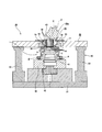
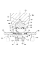
- Sectional drawing which shows one example of the rocking press apparatus which can implement the manufacturing method of 1st Embodiment of this invention in the state before starting the process for forming a hub side face spline.
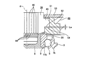
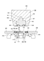
- Sectional drawing which shows one example of the said rocking press apparatus of 1st Embodiment in the state in process.
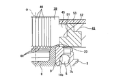
- Sectional drawing which shows one example of the said rocking press apparatus of 1st Embodiment in the state of completion of a process.
- the enlarged view which expanded the a part in FIG.
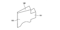
- the enlarged view which expanded the b section in FIG. The perspective view which takes out and shows one punch element.
- the top view which looked at the punch element of FIG. 5A from upper direction.
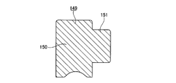
- FIG. 5B is a cross-sectional view corresponding to the line cc in FIG. 5B.
- Sectional drawing which shows a part of processing apparatus regarding 2nd Embodiment of this invention in the state before starting the process which forms a crimping part.
- a part of the processing device is placed under the caulking portion molding die on the other axial end surface of the cylindrical portion of the hub body following the state shown in FIG. Sectional drawing shown in the state which contacted the end surface.
- a part of the processing device is brought into contact with the upper end surface of the caulking portion molding die following the state shown in FIG. Sectional drawing shown in a state.
- FIG. 17 which shows an example of the said rocking press apparatus of 2nd Embodiment.
- FIG. 20 is a cross-sectional view corresponding to the line cc in FIG. 20B in an example of the rocking press device of the second embodiment.
- Sectional drawing which shows a part of processing apparatus regarding 3rd Embodiment of this invention in the state before starting the process which forms a hub side face spline.
- Sectional drawing which shows a part of processing apparatus of 3rd Embodiment in the state which made the some roller contact
- Sectional drawing which shows a part of the processing apparatus of 3rd Embodiment in the state after processing the crimping
- the perspective view which takes out and shows one shaping
- the top view which looked at the shaping
- FIG. 9 shows a wheel drive bearing unit described in Patent Document 1.
- This unit has a structure in which a rolling bearing unit for supporting a wheel, which is a kind of bearing unit that is an object of the present invention, is incorporated.
- the wheel drive bearing unit shown in FIG. 9 is formed by combining a wheel support rolling bearing unit 1 and a constant velocity joint outer ring 2.
- the wheel-supporting rolling bearing unit 1 includes an outer ring 3, a hub 4, and a plurality of rolling elements (balls in the illustrated example) 5 and 5.
- the outer ring 3 has a stationary-side flange 6 on the outer peripheral surface and double row outer ring raceways 7a and 7b on the inner peripheral surface.
- the hub 4 is formed by combining a hub body 8 and an inner ring 9.
- the hub body 8 has a rotation-side flange 10 at a portion near one end of the outer peripheral surface in the axial direction.
- the hub body 8 has an inner ring raceway 11a on one axial side at an axially intermediate portion of the outer peripheral surface.
- the hub body 8 has a small-diameter step 12 at the other axial end of the outer peripheral surface, and a center hole 13 at the center.
- one side in the axial direction means the outside in the width direction of the vehicle in an assembled state in an automobile. That is, the left side of FIG. 9 and the lower side of FIGS. 1 to 4A, 6A and 6B are referred to as “one side” with respect to the axial direction, and on the contrary, the right side of FIG. The upper side of 1-4A, 6A, 6B is referred to as the “other side” with respect to the axial direction.
- a small-diameter portion 14 through which a flange portion 16 of a bolt 15 as a coupling member can be inserted through a predetermined guide gap is provided at one end portion in the axial direction of the center hole 13.
- the inner ring 9 has an inner ring raceway 11b on the other side in the axial direction of the outer peripheral surface, and is fitted on the small-diameter step portion 12 of the hub body 8 with an interference fit.
- Each of the rolling elements 5 and 5 is provided between the outer ring raceways 7a and 7b and the inner ring raceways 11a and 11b so as to be capable of rolling plurally for each row.
- a portion protruding from the other axial end opening of the inner ring 9 is plastically deformed radially outward to cause caulking portion 20. Is forming.
- An appropriate preload is applied to each of the rolling elements 5 and 5 by suppressing the other axial end surface of the inner ring 9 by the caulking portion 20.
- a hub-side face spline 21 that is an uneven portion in the circumferential direction is formed over the entire circumference.
- the tooth tip surface of the hub-side face spline 21 is a plane perpendicular to the central axis of the hub body 8.
- the constant velocity joint outer ring 2 includes a cup-shaped mouth portion 22, an end wall portion 23 that is a bottom portion of the mouth portion 22, and a cylindrical shape that extends from the center portion of the end wall portion 23 in one axial direction. And a shaft portion 24.
- a central hole of the shaft portion 24 is a screw hole 25.
- a joint-side face spline 26 that is an uneven portion in the circumferential direction is formed over the entire circumference at a portion near the outer periphery of one end surface in the axial direction of the end wall portion 23.
- the tooth tip surface of the joint-side face spline 26 is a plane perpendicular to the central axis of the constant velocity joint outer ring 2.
- the number of teeth of the joint-side face spline 26 is the same as the number of teeth of the hub-side face spline 21.
- the hub body 8 and the joint-side face splines 21 and 26 are engaged with each other while the central axes of the hub body 8 and the constant velocity joint outer ring 2 are aligned with each other. And the transmission of the rotational force between the constant velocity joint outer ring 2. Further, in this state, the flange portion 16 of the bolt 15 is inserted into the small diameter portion 14 of the center hole 13 of the hub body 8 from one axial direction, and the male screw portion 17 provided at the tip portion of the flange portion 16 is It is screwed into the screw hole 25 and further tightened. Accordingly, the hub body 8 and the constant velocity joint outer ring 2 are coupled and fixed in a state where the hub body 8 is sandwiched between the head 18 of the bolt 15 and the constant velocity joint outer ring 2. .
- the stationary side flange 6 of the outer ring 3 is coupled and fixed to a suspension device, and the wheel (drive wheel) is attached to the rotation side flange 10 of the hub body 8.
- a brake rotating member such as a disk.
- a tip end portion of a drive shaft (not shown) that is rotationally driven by the engine via the transmission is spline-engaged with the inside of the constant velocity joint inner ring 27 provided inside the constant velocity joint outer ring 2.
- the rotation of the constant velocity joint inner ring 27 is transmitted to the constant velocity joint outer ring 2 and the hub main body 8 via a plurality of balls 28 to rotate the wheels.
- the outer ring 3 is disposed around the hub body 8, and the outer ring raceways 7a, 7b, between the outer ring raceway 7a on one axial side and the inner ring raceway 11a on one axial side, the rolling elements 5, 5 are provided in a state of being held by a cage 29a on one axial side.
- the rolling elements 5 and 5 are installed around the inner ring raceway 11b on the other axial side formed on the outer peripheral surface of the inner ring 9 while being held by the cage 29b on the other axial side.
- the inner ring 9 is externally fitted to the small-diameter step portion 12 formed at the other axial end portion of the hub body 8 with an interference fit.
- the rolling elements 5 and 5 for example, the rolling elements 5 and 5 provided in the axially other side row
- the moving surface is brought into contact with the outer ring raceway 7b on the other axial side formed on the inner peripheral surface of the outer ring 3 near the other end in the axial direction.
- the cylindrical portion 19 formed at the other axial end portion of the hub body 8 is plastically deformed radially outward to form the caulking portion 20.
- the inner ring 9 is fixed to the hub body 8 by pressing the other end surface in the axial direction of the inner ring 9 in the axial direction by the caulking portion 20.
- the hub-side face spline 21 is formed by performing rocking forging using a roll 30 having an axis ⁇ .
- members other than the hub body 8 (outer ring 3, rolling elements 5, 5, inner ring 9, etc.) are omitted from the members constituting the wheel support rolling bearing unit 1. .
- the front end surface of the roll 30 (lower end surface in FIG. 10) forms a processing surface 31 in which convex portions (processing teeth) 33 and 33 and concave portions 34 (see FIG.
- FIG. 12 is a schematic diagram showing a state in which a hub-side face spline is formed by swing forging.
- the roll 30 is supported so as to be rotatable about its own central axis ⁇ .
- the roll 30 is When the hub body 8 is rotated about the central axis ⁇ , the front end surface of the convex portions 33, 33 provided on the processing surface 31 and the other end surface in the axial direction of the caulking portion 20 are frictionally engaged.
- the roll 30 rotates (rotates) about its own central axis ⁇ .
- the roll 30 is centered on the central axis ⁇ of the hub body 8.
- the roll 30 rotates on the basis of the engagement (meshing) between the concave portion 34 and the convex portions 33, 33 constituting the processed surface 31 and the hub-side face spline 21.
- the other end surface in the axial direction of the caulking portion 20 is plastically deformed to form the hub side face spline 21 on the other end surface in the axial direction of the caulking portion 20, and further, the hub side face spline 21.
- the manufacturing method of the wheel support rolling bearing unit 1 as described above has room for improvement in terms of reducing the manufacturing cost while ensuring the durability of the wheel support rolling bearing unit 1. That is, the operation of forming the hub-side face spline 21 (oscillating forging) is performed in a state in which the processing surface 31 of the roll 30 is pressed against the other end surface in the axial direction of the caulking portion 20 with a large force (pressing force) F. The roll 30 is rotated by rotating around the central axis ⁇ of the hub body 8.
- FIG. 11 shows the relationship between the inclination angle ⁇ and the maximum value of the pressing force F.
- the tilt angle ⁇ is 5 degrees
- a pressing force F about twice that when the tilt angle ⁇ is 15 degrees is required.
- the inclination angle ⁇ is large, the straightness of the cross-sectional shape of the tooth surfaces (tooth side surfaces) of the teeth 32 constituting the hub-side face spline 21 is lowered. That is, in the case of the manufacturing method of the wheel bearing rolling bearing unit 1 as described above, among the plurality of recesses 34 constituting the processing surface 31 of the roll 30, the central position of one recess 34 (the roll 30 In the circumferential direction) is pressed against the other end surface in the axial direction of the caulking portion 20 (through the central position of the one recess 34, a virtual line ⁇ parallel to the central axis ⁇ of the roll 30 is The tooth surface of the tooth 32 formed by the one concave portion 34 (that is, the tooth 32 should be formed) in a state where the hub body 8 exists in a virtual plane including the central axis ⁇ and the central axis ⁇ .
- the inclination angle of the circumferential side surface of the one concave portion 34 with respect to the tooth surface of the tooth 32 is that of one convex portion 33 among the plurality of convex portions 33, 33 constituting the processing surface 31 of the roll 30. It becomes the largest in the state ⁇ state shown in (B) or (D) of FIG. 12 ⁇ in which the center position is pressed against the other end surface in the axial direction of the caulking portion 20.
- the inclination angle of the inner surface of the recess 34 with respect to the tooth surface of the tooth 32 increases as the inclination angle ⁇ of the central axis ⁇ of the roll 30 with respect to the central axis ⁇ of the hub body 8 increases.
- FIG. 13 is a schematic diagram showing face spline teeth formed by rocking forging
- FIG. 13A is a schematic diagram when the inclination angle of the central axis of the roll with respect to the central axis of the hub body is 5 degrees
- FIG. 13B is a schematic view when the inclination angle of the central axis of the roll with respect to the central axis of the hub body is 15 degrees.
- a stepped portion 35 is formed like a portion that is smaller or surrounded by a chain line ⁇ , and the straightness of the cross-sectional shape of the tooth surface of the tooth 32 is lowered.
- the hub side face spline 21 is configured in a state where the hub side face spline 21 and the joint side face spline 26 (see FIG. 9) formed on the constant velocity joint outer ring 2 are engaged with each other.
- the contact area between the tooth surfaces of the teeth 32 and the teeth constituting the joint-side face spline 26 is reduced, and the meshing portion of the hub-side face spline 21 and the joint-side face spline 26 is extended. There is a possibility that it is difficult to ensure the durability of the entire wheel bearing rolling bearing unit 1.
- FIG. 27 shows a wheel drive bearing unit described in Patent Document 1.
- This unit has a structure in which a rolling bearing unit for supporting a wheel, which is a kind of bearing unit that is an object of the present invention, is incorporated.
- the wheel driving bearing unit shown in FIG. 27 is formed by combining a wheel supporting rolling bearing unit 101 and a constant velocity joint outer ring 102.
- the wheel supporting rolling bearing unit 101 includes an outer ring 103, a hub 104, and a plurality of rolling elements (balls in the illustrated example) 105 and 105.
- the outer ring 103 has a stationary side flange 106 on the outer peripheral surface and double row outer ring raceways 107a and 107b on the inner peripheral surface.
- the hub 104 is formed by combining a hub main body 108 and an inner ring 109.
- the hub body 108 has a rotation-side flange 110 at a portion near one end in the axial direction on the outer peripheral surface.
- the hub body 108 has an inner ring raceway 111a on one axial side at the axially intermediate portion of the outer peripheral surface.
- the hub body 108 has a small-diameter step 112 at the other axial end of the outer peripheral surface, and an axial center hole 113 at the radial center. At one end in the axial direction of the center hole 113, there is a small-diameter portion 114 through which the flange 116 of the bolt 115 as a coupling member can be inserted through a predetermined guide gap.
- one side in the axial direction means the outside in the width direction of the vehicle in an assembled state in an automobile. That is, the left side of FIG. 27 and the lower side of FIGS. 14, 16 to 18, 21 to 24 are referred to as “one side” with respect to the axial direction, and conversely, the right side of FIG. 14, 16 to 18 and 21 to 24 are referred to as “other side” with respect to the axial direction.
- the inner ring 109 has an inner ring raceway 111b on the other side in the axial direction of the outer peripheral surface, and is fitted on the small-diameter step portion 112 of the hub body 108 with an interference fit.
- Each of the rolling elements 105, 105 is provided between the outer ring raceways 107a, 107b and the inner ring raceways 111a, 111b so that a plurality of rolling elements can be rolled for each row.
- a portion protruding from the other axial end opening of the inner ring 109 is plastically deformed radially outward so as to be caulked portion 120. Is forming.
- each rolling element 105 is provided.
- 105 is provided with an appropriate preload, and separation of the inner ring 109 from the hub body 108 is prevented.
- a hub-side face spline 121 that is an uneven portion in the circumferential direction is formed over the entire circumference.
- the tooth tip surface of the hub-side face spline 121 is a plane perpendicular to the central axis of the hub body 108.
- the constant velocity joint outer ring 102 includes a cup-shaped mouth portion 122, an end wall portion 123 that is a bottom portion of the mouth portion 122, and a cylindrical shape that extends from the center portion of the end wall portion 123 in one axial direction. And a shaft portion 124.
- a central hole of the shaft portion 124 is a screw hole 125.
- a joint-side face spline 126 which is an uneven portion in the circumferential direction, is formed over the entire circumference at a portion near the outer periphery of one end surface in the axial direction of the end wall portion 123.
- the tooth tip surface of the joint-side face spline 126 is a plane perpendicular to the center axis of the constant velocity joint outer ring 102.
- the number of teeth of the joint-side face spline 126 is the same as the number of teeth of the hub-side face spline 121.
- the hub main body 108 and the joint-side face splines 121 and 126 are engaged with each other while the central axes of the hub main body 108 and the constant velocity joint outer ring 102 are aligned with each other, whereby the hub main body 108 is engaged. And a rotational force between the constant velocity joint outer ring 102 can be transmitted. Further, in this state, the flange portion 116 of the bolt 115 is inserted into the small diameter portion 114 of the center hole 113 of the hub body 108 from one side in the axial direction, and the male thread portion 117 provided at the distal end portion of the flange portion 116 is It is screwed into the screw hole 125 and further tightened. Thus, the hub main body 108 and the constant velocity joint outer ring 102 are coupled and fixed in a state where the hub main body 108 is sandwiched between the head 118 of the bolt 115 and the constant velocity joint outer ring 102. .
- the stationary side flange 106 of the outer ring 103 is coupled and fixed to a suspension device, and the wheel (drive wheel) is connected to the rotation side flange 110 of the hub body 108.
- a brake rotating member such as a disk.
- a tip portion of a drive shaft (not shown) that is rotationally driven by the engine via the transmission is spline-engaged with the inner side of the constant velocity joint inner ring 127 provided inside the constant velocity joint outer ring 102.
- the rotation of the constant velocity joint inner ring 127 is transmitted to the constant velocity joint outer ring 102 and the hub main body 108 via a plurality of balls 128 to rotate the wheels.
- the outer ring 103 is arranged around the hub body 108, and the outer ring raceways 107a and 107b are arranged.
- the rolling elements 105 and 105 are provided between the outer ring raceway 107a on one axial side and the inner ring raceway 111a on one axial side in a state of being held by the cage 129a on one axial side.
- each of the rolling elements 105, 105 is installed around the inner ring race 111b on the other axial side formed on the outer peripheral surface of the inner ring 109 in a state of being held by the cage 129b on the other axial side.
- the inner ring 109 is externally fitted with a small diameter step 112 formed at the other axial end of the hub main body 108 with an interference fit.
- the rolling elements 105, 105 for example, the rolling elements 105, 105 provided in the other axial row
- the moving surface is brought into contact with the outer ring raceway 107b on the other axial side formed on the inner peripheral surface of the outer ring 103 near the other end in the axial direction.
- the caulking portion 120 is formed by plastically deforming the cylindrical portion 119 formed at the other axial end portion of the hub body 108 radially outward.
- the hub-side face spline 121 is formed on the other axial end surface of the caulking portion 120.
- the caulking portion 120 and the hub-side face spline 121 are pressed against the other end surface in the axial direction of the hub main body 108 with a processing surface of a roll having a central axis inclined by a predetermined angle with respect to the central axis of the hub main body 108. Then, the roll is rotated (revolved) around the central axis of the hub body 108 and rotated (rotated) around the central axis of the hub body 108, so that it is formed with a relatively small processing force.
- a processing surface of a roll having a central axis inclined by a predetermined angle with respect to the central axis of the hub main body 108.
- the load applied to the other axial end portion of the hub main body 108 from the processed surface of the roll is only one load in the circumferential direction. That is, when the above-described swing forging is performed, a large offset load (for example, from the central axis of the hub main body 108 to the radial direction) from the processing surface of the roll to the other axial end of the hub main body 108. A load acting on the offset position) is applied. For this reason, after the caulking portion 120 and the hub-side face spline 121 are formed, the force with which the caulking portion 120 restrains the other end surface in the axial direction of the inner ring 109 may be nonuniform in the circumferential direction.
- the outer ring 3 is arranged around the hub body 8 and a plurality of outer ring raceways 7a on one axial side and a plurality of inner ring raceways 11a on one axial side are disposed in the same manner as the manufacturing method described above.
- the rolling elements 5 and 5 are provided in a state where they are held by a cage 29a (see FIG. 9) on one axial side.
- the rolling elements 5, 5 are installed around the inner ring raceway 11 b on the other axial side formed on the outer peripheral surface of the inner ring 9 while being held by the cage 29 b on the other axial side.
- the inner ring 9 is externally fitted to the small-diameter step portion 12 formed at the other axial end portion of the hub body 8 with an interference fit.
- the caulking portion 20 is formed by plastically deforming the cylindrical portion 19 formed at the other axial end portion of the hub body 8 radially outward.
- FIG. 1 is a cross-sectional view showing an example of an oscillating press apparatus capable of performing the manufacturing method according to the first embodiment of the present invention before a process for forming a hub-side face spline is started.
- FIG. 2 is a cross-sectional view showing an example of the oscillating press device shown in FIG. 1 in a state during processing.
- FIG. 3 is a cross-sectional view showing an example of the oscillating press device in a state of completion of processing.
- 4A is an enlarged view in which the a part in FIG. 2 is enlarged
- FIG. 4B is an enlarged view in which the b part in FIG. 3 is enlarged.
- the oscillating press device 36 includes a base 37, a holder 38 supported and fixed to the other side surface in the axial direction of the base 37, a roll 30a, a forming punch 39, a punch lifting mechanism 40, a control device (not shown). As shown).
- the control device includes a circuit and is configured to control the entire swing press device 36 in an integrated manner.
- the holder 38 On the other side surface in the axial direction, the holder 38 is provided with a holding concave portion 42 provided at one end portion in the axial direction of the hub body 8 and capable of inserting a cylindrical portion 41 called a pilot portion without rattling.
- the roll 30a is supported so as to be able to rotate (rotate) about its own central axis ⁇ inclined by a predetermined angle ⁇ with respect to the central axis ⁇ of the hub body 8, and has a tip surface (FIG. 1 to FIG. 1). 3 (lower end surface) is a truncated cone-shaped pressing surface 43.
- the predetermined angle ⁇ is set to 15 degrees or more and 30 degrees or less (15 ⁇ ⁇ ⁇ 30).
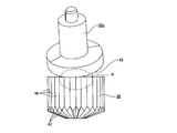
- FIG. 5A is a perspective view showing one punch element taken out
- FIG. 5B is a plan view of the punch element of FIG. 5A as viewed from above
- FIG. 5C corresponds to the line cc in FIG. 5B.
- FIG. The molding punch 39 is formed in a substantially cylindrical shape as a whole, and has the same number of machining teeth 44, 44 as the number of teeth of the hub-side face spline 21 on one end face in the axial direction at equal intervals in the circumferential direction.
- a flange portion 45 protruding radially outward is provided over the entire circumference in the axially intermediate portion of the outer peripheral surface.
- Such forming punch 39 is divided into each of the machining teeth 44, 44 in the same number as each of the machining teeth 44, 44 (the center position of the tooth base existing between the machining teeth 44, 44).
- the punch elements 46 and 46 are divided by (1).
- the shape of the forming punch 39 viewed from the axial direction is a sector shape, and an element main body 47 in which one processing tooth 44 is provided on one end face in the axial direction, and the axial direction of the outer peripheral surface of the element main body 47
- a punch element 46 composed of a projecting portion 48 provided at an intermediate portion is combined in the circumferential direction.
- the punch holding plates 49 constituting the punch lifting mechanism 40 allow the punch elements 46 and 46 to be displaced only in the axial direction with respect to the punch holding plate 49. It is supported by.
- the punch raising / lowering mechanism 40 is for raising and lowering the forming punch 39 (displacement in the axial direction of the hub main body 8), and between the punch holding plate 49, the punch holding plate 49 and the base 37.
- the hydraulic cylinders 50 and 50 provided are provided.
- the punch holding plate 49 is provided with a holding hole 51 at the center for holding the forming punch 39 in the radial direction and the circumferential direction without rattling.
- the holding hole 51 is provided with a stepped surface portion 52 at the intermediate portion in the axial direction for connecting the small diameter portion on one axial side and the large diameter portion on the other axial side.
- the dimension regarding the axial direction of the said large diameter part is larger than the dimension (thickness) regarding the axial direction of the flange part 45 of the said shaping
- an annular closing plate 53 is supported and fixed around the other axial opening of the holding hole 51 in a state where the half axial portion of the forming punch 39 is inserted into the holding hole 51.
- Such a punch holding plate 49 is supported by the hydraulic cylinders 50 and 50 so as to be movable up and down with respect to the base 37 (position adjustment in the axial direction is possible).
- each of the hydraulic cylinders 50, 50 is operated to displace the punch holding plate 49 downward, so that one axial end surface of the forming punch 39 held on the punch holding plate 49 and the caulking portion 20 The other axial end surface is brought into contact.
- the punch holding plate 49 is further displaced downward to displace the forming punch 39 in the other axial direction with respect to the holding plate 49.
- the other end surface in the axial direction of the flange portion 45 of 39 and the inner diameter side portion of one side surface in the axial direction of the closing plate 53 are brought into contact with each other. In this state, a gap 54 ⁇ see FIG.
- the axial dimension L 54 of the gap 54 is, teeth 32 of the hub-side face splines 21 so as to be the same as the tooth depth (see FIG. 12), Ya the flange portion 45 The axial dimension of the holding hole 51 is restricted.
- the ram that supports the roll 30 a is lowered, and the pressing surface 43 of the roll 30 a is brought into contact with the other axial end surface of the forming punch 39.
- the roll 30a is rotated around the central axis ⁇ of the hub body 8 in a state where the other axial end surface of the forming punch 39 is pressed with a predetermined pressing force by the pressing surface 43 of the roll 30a. That is, in a state where the other axial end surfaces of the punch elements 46, 46 constituting the forming punch 39 are directed to one axial direction and pressed by the pressing surface 43 of the roll 30a with a predetermined pressing force, the roll 30a is The hub body 8 is rotated around the central axis ⁇ .
- the punch elements 46 and 46 that are in contact with the pressing surface 43 of the roll 30a are pressed toward one axial direction, and the processing teeth 44 formed on one axial end surface of the punch elements 46 and 46, 44 is pressed against the other end surface in the axial direction of the caulking portion 20 to plastically deform the other end surface in the axial direction of the caulking portion 20.
- the punch elements 46, 46 pressed by the pressing surface 43 of the roll 30 a are arranged so that the roll 30 a rotates (revolves) around the central axis ⁇ of the hub body 8. The circumferential direction shifts in the same direction as the revolution direction.
- the plurality of punch elements (a plurality of elements) 46 are arranged so as to be independently movable at least in the axial direction.
- the punch raising / lowering mechanism (mechanism) 40 moves a part of the plurality of punch elements 46 (one punch element 46 or a small number of punch elements 46) in the axial direction to move the first region of the bearing unit 1 (workpiece). And a second part of the bearing unit 1 (workpiece) by moving another part (one punch element 46 or a small number of punch elements 46) of the plurality of punch elements 46 in the axial direction.
- a pressing mode In this plastic working, the press area changes along the circumferential direction.
- FIG. 6A is a side view showing a roll and a molding punch taken out
- FIG. 6B is an enlarged view in which a portion d in FIG. 6A is enlarged.
- the hub out of both circumferential edges of the other axial end surface of one punch element 46 out of the punch elements 46, 46.
- the rotation direction of the roll 30a about the central axis ⁇ of the main body 8 (the direction of the arrow ⁇ in FIG. 6B) in the state where the rear edge ⁇ is pressed by the pressing surface 43 of the roll 30a.
- the rotational side rear surface of the roll 30a centered on the central axis ⁇ of the hub body 8
- the central axis ⁇ and the roll Punch element existing on the front side in the rotation direction of the roll 30a around the central axis ⁇ of the one punch element 46 in a state where a virtual plane including the central axis ⁇ of 30a exists on the same plane
- the side edge ⁇ on the one punch element 46 side and the pressing surface 46 of the roll 30a are in contact or close to each other (that is, the rotation of the roll).
- the other end surface in the axial direction of the punch element that is adjacent to the front side in the direction is not strongly pressed).
- the pressing amount in the axial direction of the hub body is adjusted.
- FIG. 7A schematically shows a cross section of a contact portion between the pressing surface 43 of the roll 30 a and one axial end surface of the forming punch 39.
- FIG. 7B shows a state in which FIG. 7A is viewed from the left. That is, FIG. 7B shows the outer shape of the pressing surface 43 of the roll 30a, the origin, the radially outer side of the contact portion between the pressing surface 43 of the roll 30a and one axial end surface of the forming punch 39.
- the maximum value L 46 of the width of the punch element 46, 46 (the width in the circumferential direction of the forming punch 39), when the total number of each of these punch elements 46, 46 is N, the following (3) It is expressed by a formula.
- the width L 46 represented by the equation (3) into the equation (2), the central axis of the circumferentially opposite side edges of the other axial end surface of the one punch element 46 can be obtained.
- the side edge ⁇ on the one punch element 46 side, and the roll Pressing amount ⁇ d max at which the pressing surface 43 of 30a does not come into contact (the upper limit value of the pressing amount ⁇ d of each of the punch elements 46 and 46 per rotation around the central axis ⁇ of the hub body 8 of the roll 30a) Can be obtained approximately.
- the pressing amount ⁇ d is adjusted to 0.13 to 0.3 [mm].
- the roll 30a is supported so as to be able to rotate (rotate) about its own central axis ⁇ . Therefore, when the roll 30a is rotated about the central axis ⁇ of the hub body 8, the roll 30a is based on the frictional engagement between the pressing surface 43 of the roll 30a and the other axial end surface of the forming punch 39. 30a rotates (rotates) about its own central axis ⁇ .
- the manufacturing cost can be reduced while ensuring the durability of the wheel support rolling bearing unit 1. That is, in the case of this embodiment, the other axial end surface of the molding punch 39 is set to the roll 30a in a state where the one axial end surface of the molding punch 39 is opposed to the other axial end surface of the caulking portion 20.
- the roll 30 a is rotated about the central axis ⁇ of the hub body 8 while being pressed by the pressing surface 43. Accordingly, the hub side face is pressed against the other axial end surface of the caulking portion 20 by pressing the processing teeth 44, 44 formed on one axial end surface of the molding punch 39 against the other axial end surface of the caulking portion 20.
- the spline 21 is formed.
- the punch elements 46 and 46 constituting the forming punch 39 can only be displaced in the axial direction. Therefore, even if the other axial end surfaces of the punch elements 46, 46 are pressed by the pressing surface 43 of the roll 30a while rotating the roll 30a around the central axis ⁇ of the hub body 8,
- the tooth surfaces of the processing teeth 44, 44 are not inclined with respect to the tooth surfaces of the teeth 32 constituting the hub-side face spline 21. Accordingly, it is possible to prevent the occurrence of local contact between the tooth surfaces of the processed teeth 44 and 44 and the axial end surfaces of the caulking portions 20 such that the tooth surfaces of the teeth 32 are locally plastically deformed. .
- each tooth 32 can be improved, and the hub-side face spline 21 and the joint-side face spline 26 (see FIG. 9) formed on the constant velocity joint outer ring 2 are engaged with each other.
- the contact area between the tooth surfaces of the teeth 32 constituting the hub-side face spline 21 and the teeth constituting the joint-side face spline 26 can be sufficiently increased.
- the pressing surface 43 of the roll 30a is directed toward the other end surface in the axial direction of the caulking portion 20 via the forming punch 39.
- the pressing force (pressing force) F can be prevented from becoming excessively large.
- the roll 30a centering on the central axis ⁇ among both circumferential edges of the other axial end face of the punch element 46 of the punch elements 46, 46.
- the inclination angle ⁇ of the central axis ⁇ of the roll 30a with respect to the central axis ⁇ of the hub body 8 exceeds 30 degrees, the pressing surface 43 of the roll 30a and the molding There is a possibility that the contact area with the other end surface in the axial direction of the punch 39 is reduced, the contact surface pressure between these two surfaces is excessively increased, and it is difficult to ensure the durability of the pressing surface 43 of the roll 30a. . Therefore, in the present embodiment, the inclination angle ⁇ is set to 30 degrees or less.
- the outer peripheral surface of the molding punch is not provided with a flange portion protruding radially outward, and the outer diameter of the outer peripheral surface of the molding punch is not changed in the axial direction.
- One cylindrical surface can also be used. That is, the molding punch is a combination of a plurality of punch elements 46a provided with processing teeth 44 on one axial end face as shown in FIGS. 8A to 8C.
- 8A is a view similar to FIG. 5A showing another example of the punch element
- FIG. 8B is a view similar to FIG. 5B showing another example of the punch element
- FIG. 8C is a view different from the punch element. It is a figure similar to FIG. 5C which shows an example.
- the displacement amount of the roll 30a in the axial direction of the hub body 8 is detected, and when the displacement amount becomes the same as the tooth height of the teeth 32 constituting the hub-side face spline 21, Processing for forming the hub-side face spline 21 is completed.
- the other axial end surface of one punch element 46 is used.
- the one punch in the state where the rotation direction rear side edge of the roll 30a centering on the central axis ⁇ of the hub body 8 is pressed by the pressing surface 43 of the roll 30a.
- the circumferential edges on the other end face in the axial direction of the punch element 46 that is adjacent to the front side in the rotational direction of the roll 30a (left side in FIG.
- FIG. 14 is a sectional view showing a part of the processing apparatus according to the second embodiment of the present invention in a state before starting the processing for forming the caulking portion.
- FIG. 15 is a schematic side view of a processing apparatus, with a part omitted, in one example of the oscillating press apparatus according to the second embodiment.
- FIG. 16 shows an example of the oscillating press device according to the second embodiment, in which a part of the processing device is caulked to the other axial end surface of the cylindrical portion of the hub body following the state shown in FIG. It is sectional drawing shown in the state which contacted the lower end surface of the shaping
- FIG. 17 shows an example of the oscillating press device according to the second embodiment, in which a part of the processing device is placed on the upper end surface of the caulking portion molding die following the state shown in FIG. It is sectional drawing shown in the state contact
- FIG. 18 shows a state after processing the cylindrical portion of the hub body into a caulking portion in a part of the processing device in one example of the oscillating press device of the second embodiment, following the state shown in FIG. It is sectional drawing shown by.
- FIG. 19A is an enlarged view of a portion a in FIG. 17 showing an example of the oscillating press device of the second embodiment.
- FIG. 19B is an enlarged view of a portion b in FIG. FIG.
- FIG. 20A is a perspective view showing one mold element taken out from an example of the oscillating press device of the second embodiment.
- FIG. 20B is a plan view of the mold element of FIG. 20A as viewed from above.
- 20C is a cross-sectional view corresponding to the line cc in FIG. 20B.
- the outer ring 103 and the hub 104 (the hub main body 108 having the inner ring raceway 111a on one axial side on the outer peripheral surface in the axial direction, and An inner ring 109) having an inner ring raceway 111b on the other side in the axial direction on the outer peripheral surface, and a plurality of rolling elements 105, 105, and a caulking portion 120 is formed on the inner end in the axial direction of the hub body 108, Further, the wheel support rolling bearing unit 101 in which the hub-side face spline 121 is formed on the other end face in the axial direction of the caulking portion 120 will be described.
- the cylindrical portion 119 provided at the other axial end portion of the hub body 108 is subjected to plastic working so that the caulking portion 120 (the caulking portion 120 before the hub-side face spline 121 is formed) is formed.
- a method of forming will be described. Manufacturing method and assembling method of each member constituting the wheel supporting rolling bearing unit 101 until just before the caulking portion 120 is formed, and formation of the hub-side face spline 121 after the caulking portion 120 is formed Since the method is the same as a widely known method including the assembly method described above, the description thereof is omitted in this embodiment.
- the vertical direction means the vertical direction of FIGS. 14 to 19B.
- the vertical direction in FIGS. 14 to 19B does not necessarily coincide with the vertical direction during processing.
- a processing device (manufacturing device) for forming the caulking portion 120 includes a base 130 (shown only in FIG. 15), and a holder 131 (shown only in FIG. 15) supported and fixed on the upper surface of the base 130. , A pressing unit 132, a pressing unit drive mechanism 133, a caulking part molding die 134, a molding die lifting mechanism 135, and a control device (not shown).
- the control device includes a circuit and is configured to control the entire swing press device 36 in an integrated manner.
- the holder 131 aligns the central axis of the hub main body 108 in the vertical direction (vertical direction), and the wheel bearing rolling bearing unit 101 with the other axial end of the hub main body 108 facing upward. Is to hold.
- the pressing unit 132 includes a head 136, a roller jig 137, and a plurality of (for example, 2 to 6) rollers 138 and 138, and is disposed above the hub body 108.
- the central axis of the head 136 coincides with the central axis of the hub body 108.
- the head 136 has a bottomed mounting hole 139 that opens at the center in the radial direction of the lower end surface.
- the roller jig 137 is formed in a stepped columnar shape, with a large-diameter columnar portion 140 at the lower end, an intermediate-diameter columnar portion 141 at the middle in the vertical direction, and a small-diameter columnar portion 142 at the upper end. Prepare for the same axis.
- the roller jig 137 has holding recesses 143 and 143 at a plurality (the same number as the rollers 138 and 138) at equal intervals in the circumferential direction of the lower end surface of the large-diameter cylindrical portion 140. Yes.
- Such a roller jig 137 is fixedly mounted in the mounting hole 139 of the head 136.
- the mounting hole 139 is a bottomed stepped hole.
- An outer diameter side retaining ring groove (not shown) is formed on the inner peripheral surface of the small diameter hole provided at the upper end portion of the mounting hole 139, and the outer diameter side retaining ring groove has a retaining ring (not shown).
- a radially outer half is housed.
- the diameter dimension of the groove bottom of the said outer diameter side retaining ring groove is larger than the outer diameter dimension in the free state of the said retaining ring.
- the retaining ring is elastically expanded, and then the retaining ring is formed on the outer peripheral surface of the small-diameter cylindrical portion 142.
- the retaining ring is aligned with the side retaining ring groove, the retaining ring is elastically restored, and the retaining ring is spanned between the outer diameter side and inner diameter side retaining ring grooves, whereby the mounting hole 139 is provided. This prevents the roller jig 137 from coming out.
- the head 136 and the roller jig are formed by spline-engaging the inner peripheral surface of the medium-diameter hole provided in the vertical middle portion of the mounting hole 139 and the outer peripheral surface of the medium-diameter cylindrical portion 141. Torque transmission to and from 137 is possible. Further, the large-diameter cylindrical portion 140 is fitted in the large-diameter hole provided at the lower end of the mounting hole 139 without rattling.
- the pressing unit drive mechanism 133 is for rotating and moving up and down (displacement in the axial direction of the hub main body 108) of the pressing unit 132, and is supported by a support column 166 fixed to the base 130. .
- Such a pressing unit drive mechanism 133 is driven by an electric motor 144 to directly rotate (without a speed reduction mechanism), and a spindle 145 arranged in the vertical direction, and a hydraulic type that drives the spindle 145 up and down. Cylinder 146.
- a head 136 (not shown in FIG. 15) of the pressing unit 132 is attached and fixed to the lower end portion of the spindle 145.
- the caulking part forming die 134 is configured in a substantially cylindrical shape as a whole, and is disposed in a portion between the hub main body 108 and the pressing unit 132 in the vertical direction.
- the caulking portion forming die 134 has a shape that matches the other end surface in the axial direction of the caulking portion 120 at a lower end surface that is one end surface in the axial direction (a circular concave surface having a substantially arc-shaped cross section). 147 is provided, and a flange portion 148 projecting radially outward is provided at the axially intermediate portion of the outer peripheral surface over the entire circumference.
- Such a caulking portion molding die 134 has a plurality of molding elements 149 and 149 (for example, 20 to 40) divided in the circumferential direction (for example, in the circumferential direction around the central axis of the hub body 108). It is configured by combining a plurality of mold elements 149, 149) arranged side by side.
- the caulking part forming die 134 has a fan-shaped shape when viewed from the axial direction, and an element main body 150 having a lower end surface provided with a part in the circumferential direction of the processed surface 147, and an outer periphery of the element main body 150
- the mold element 149 is formed by combining in a circumferential direction a molding element 149 formed from a protruding portion 51 which is a part in the circumferential direction of the flange portion 148 provided at an axially intermediate portion of the surface.
- the caulking part mold 134 having such a configuration allows the respective mold elements 149 and 149 to be axially displaced independently from each other with respect to the holding plate 152 constituting the mold lifting mechanism 135. It is supported by.
- the mold raising / lowering mechanism 135 is for raising and lowering the caulking part molding die 134 (displacement in the axial direction of the hub main body 108), and includes a holding plate 152, the holding plate 152, and the base 130. And hydraulic or pneumatic cylinders 153 and 153 provided therebetween.
- the holding plate 152 is arranged in the horizontal direction, and a holding hole 154 for holding the caulking part molding die 134 in the radial direction and the circumferential direction is provided in the center part.
- the holding hole 154 is a stepped hole in which a lower small diameter portion and an upper large diameter portion are made continuous by a step surface portion 155.
- the axial dimension of the large diameter part is larger than the axial dimension of the flange part 148 of the caulking part molding die 134.
- an inward flange portion 167 is provided in the upper half portion of the large diameter portion.
- the holding plate 152 has a configuration that can be divided into two in the radial direction.
- annular holding plate 156 is fitted into the large diameter part of the holding hole 154.
- the center hole of the pressing plate 156 is a stepped hole in which the upper small diameter portion and the lower large diameter portion are made continuous by the step surface portion 157.
- An outward flange 168 is provided in the lower half of the outer peripheral surface of the holding plate 156.
- the upper half portion of the outer peripheral surface of the holding plate 156 is guided by the inner peripheral surface of the inward flange portion 167 so as to be able to be displaced in the axial direction without shaking in the radial direction.
- the holding plate 156 is biased in a direction approaching the stepped surface portion 155 of the holding hole 154 by a biasing spring 158 schematically shown in FIGS. 19A and 19B. Has been.
- the flange portion 148 of the caulking portion molding die 134 in the state before the start of forming the caulking portion 120 is caused by the elasticity of the biasing spring 158. It is sandwiched between the step surface portion 155 and the step surface portion 157 of the holding plate 156. In this state, a gap is formed between the upper surface of the outward flange 168 and the lower surface of the inward flange 167.
- the holding plate 152 as described above is supported by the cylinders 153 and 153 so as to be movable up and down with respect to the base 130.
- the holding plate 152 includes a machining surface 147 provided at a lower end surface of the caulking portion forming die 134 and an axial other end surface of the wheel supporting rolling bearing unit 101 held by the holder 131 (the hub body).
- the other end surface in the axial direction of the cylindrical portion 119 of the cylinder 108 is positioned above the vertical direction so as not to abut.
- the flange portion 148 of the caulking portion molding die 134 is formed between the step surface portion 155 of the holding hole 154 and the step surface portion 157 of the holding plate 156 by the elasticity of the biasing spring 158. It is in a state of being sandwiched between them. Further, the wheel support rolling bearing unit 101 holds the holder 131 in a state where the central axis of the hub body 108 coincides with the vertical direction, and the other axial end of the hub body 108 faces upward. Keep it.
- the pressing unit 132 is further displaced downward based on the operation of the pressing unit drive mechanism 133.
- the pressing unit 132 is rotationally driven in a state where the outer peripheral surfaces of the rollers 138 and 138 are pressed against the upper end surface of the caulking portion molding die 134, that is, the upper end surfaces of the molding die elements 149 and 149 so as to roll.
- the rollers 138 and 138 roll in the circumferential direction.
- each of the plurality of mold elements (plural elements) 149 is arranged to be independently movable at least in the axial direction.
- the pressing unit drive mechanism (mechanism) 133 moves part of the plurality of mold elements 149 (one mold element 149 or a small number of mold elements 149) in the axial direction to move the hub main body 108 (workpiece). ) And a mode in which another part of the plurality of mold elements 149 is moved in the axial direction to press the second region of the hub body 108 (workpiece). In this plastic working, the press area changes along the circumferential direction.
- the axial dimension L 159 of the gap 159 is such that when the caulking portion 120 is formed, one roller 138 is arranged in the circumferential direction on the upper end surface of each mold element 149, 149. Each time it passes once, it is made larger than the downward displacement amount (working stroke) of the respective mold elements 149, 149.
- the cylinders 153 and 153 prevent the gap 159 from disappearing by continuously applying a downward force to the holding plate 152.
- the processing for forming the caulking portion 120 as described above ends when a certain time has elapsed after the plastic processing of the cylindrical portion 119 is started. Until the predetermined time elapses, a press load (a load for displacing the press unit 132 downward) of the cylinder 146 (see FIG. 15) constituting the press unit drive mechanism 133 is a predetermined value. And when the pressing unit 132 is in a predetermined position, it is determined that the caulking portion 120 is properly formed. On the other hand, when the press load does not reach the predetermined value until the predetermined time elapses, or when the pressing unit 132 is not in the predetermined position, the caulking portion 120 is appropriate. It was determined that it was not formed.
- the press load 132 reaches the predetermined position while the press load reaches the predetermined value in the processing for forming the caulking portion 120 as described above. Can be terminated after a predetermined time has elapsed.
- the shaft of the hub main body 108 is processed when the axial other end portion (the caulking portion 120) of the hub main body 108 is processed. Uneven load applied to the other end in the direction can be reduced or substantially zero. That is, in the case of the present embodiment, when the caulking portion 120 is formed, the load (working force) applied to the cylindrical portion 119 provided at the other axial end portion of the hub body 108 is equal in the circumferential direction. Loads at equal intervals in the circumferential direction are applied from the arranged rollers 138 and 138 via some of the mold elements 149 and 149.
- the caulking portion 120 can be formed without substantially applying an offset load to the other axial end surface of the cylindrical portion 119. Therefore, after the caulking portion 120 is formed, the force that the caulking portion 120 suppresses the other end surface in the axial direction of the inner ring 109 can be easily made uniform over the entire circumference.
- FIG. 21 is sectional drawing which shows a part of processing apparatus regarding the 3rd Embodiment of this invention in the state before starting the process which forms a hub side face spline.
- FIG. 22 shows a part of the processing apparatus of the third embodiment in which the lower end surface of the face spline mold is brought into contact with the other end surface in the axial direction of the caulking portion of the hub body, following the state shown in FIG. It is sectional drawing shown in a state.
- FIG. 21 is sectional drawing which shows
- FIG. 23 is a cross-sectional view showing a part of the processing apparatus of the third embodiment in a state in which a plurality of rollers are brought into contact with the upper end surface of the face spline mold after the state shown in FIG. is there.
- 24 is a cross-sectional view showing a part of the processing apparatus of the third embodiment in a state after the caulking portion of the hub body is processed into a hub-side face spline following the state shown in FIG.
- FIG. 25A is an enlarged view of a portion d in FIG. 23 of the third embodiment.
- FIG. 25B is an enlarged view of an e portion in FIG. 24 of the third embodiment.
- FIG. 26A is a perspective view showing one mold element according to the third embodiment.
- FIG. 26B is a plan view of the mold element of FIG. 26A of the third embodiment as viewed from above.
- FIG. 26C is a cross-sectional view corresponding to the line ff in FIG. 26B of the third embodiment.
- the outer ring 103, the hub 104 (the hub main body 108 having the inner ring raceway 111a on one axial side on the outer circumferential surface in the axial direction, and the outer circumference And an inner ring 109) having an inner ring raceway 111b on the other side in the axial direction, and a plurality of rolling elements 105, 105, and a caulking portion 120 is formed at the inner end of the hub body 108 in the axial direction.
- a wheel support rolling bearing unit 101 in which a hub-side face spline 121 is formed on the other end surface in the axial direction of the caulking portion 120 will be described.
- a method of forming the hub-side face spline 121 by performing plastic working on the caulking portion 120 formed at the other axial end portion of the hub body 108 will be described.
- the manufacturing method and assembling method (including the method for forming the caulking portion 120) of each member constituting the wheel supporting rolling bearing unit 101 until immediately before the hub-side face spline 121 is formed have been described above. Since this method is the same as a widely known method including an assembling method and the manufacturing method of the first example of the above-described embodiment, the description thereof is omitted in this embodiment.
- the vertical direction means the vertical direction of FIGS.
- the vertical direction in FIGS. 21 to 25B does not necessarily coincide with the vertical direction during processing.
- the processing device (manufacturing device) for forming the hub-side face spline 121 includes a face spline forming die 160 as a forming die instead of the caulking portion forming die 134 (see FIGS. 14 and 16 to 18). Is different from the processing apparatus of the second embodiment described above. About the structure and operation
- the face spline molding die 160 is formed in a substantially cylindrical shape as a whole, and the processing teeth 161, 161 having the same number as the number of teeth of the hub side face spline 121 are circular on the lower end surface which is one end surface in the axial direction.
- a flange portion 162 that is formed at an equal pitch in the circumferential direction and protrudes radially outward is provided at the axially intermediate portion of the outer circumferential surface over the entire circumference.
- Such a face spline mold 160 has a plurality of mold elements 163, 163 (for example, 20 to 40 in the present embodiment. In this embodiment, the mold elements 163, 163 (the same number as the processing teeth 161, 161) are divided.
- the face-spline mold 160 has a fan-shaped shape viewed from the axial direction and an element main body 164 provided with one processing tooth 161 on the lower end surface, and an axis of the outer peripheral surface of the element main body 164.
- the mold element 163 is formed by combining in the circumferential direction a molding element 163 that is provided at a middle portion in the direction and includes a projecting portion 165 that is a part in the circumferential direction of the flange portion 162.
- the face spline molding die 160 is provided at the center of the holding plate 152 constituting the molding die lifting mechanism 135.
- the respective mold elements 163 and 163 are held without shakiness in the radial direction and the circumferential direction in a state in which they can be independently displaced in the axial direction.
- the flange portion 162 of the face spline mold 160 changes the posture of the face spline mold 160.
- the holding plate 152 is held by processing teeth 161 and 161 provided on a lower end surface of the face spline mold 160 and a holder 131 (see FIG. 15).
- the wheel-supporting rolling bearing unit 101 is positioned above the other end surface in the axial direction (the other end surface in the axial direction of the caulking portion 120) so as not to contact.
- the flange portion 162 of the face spline mold 160 is formed between the step surface portion 155 of the holding hole 154 and the step surface portion 157 of the holding plate 156 by the elasticity of the biasing spring 158. It is in a state of being sandwiched between them. Further, the wheel support rolling bearing unit 101 holds the holder 131 in a state where the central axis of the hub body 108 coincides with the vertical direction, and the other axial end of the hub body 108 faces upward. Keep it.
- a gap 159 a in the axial direction is formed between the lower surface of the flange portion 162 and the stepped surface portion 155 of the holding hole 154.
- the axial dimension L 159a of the gap 159a will be described later.
- the pressing unit 132 is further displaced downward to The pressing unit 132 is rotationally driven while the outer peripheral surfaces of the rollers 138 and 138 are pressed against the upper end surface of the face spline mold 160, that is, the upper end surfaces of the molding element 163 and 163, respectively.
- the rollers 138 and 138 roll in the circumferential direction.
- the rolling teeth of the rollers 138 and 138 are sequentially pressed against the other side surface in the axial direction of the mold elements 163 and 163, so that the processing teeth 161 and 161 of the mold elements 163 and 163 are pressed.
- the other end surface in the axial direction of the caulking portion 120 is plastically deformed to form the hub-side face spline 121.
- the axial dimension L 159a of the gap 159a is such that when the hub-side face spline 121 is formed, one roller 138 is attached to the upper end surface of each of the mold elements 163 and 163. Each time it passes once in the circumferential direction, it is larger than the downward displacement amount (machining stroke) of the respective mold elements 163 and 163.
- the cylinders 153 and 153 prevent the gap 159a from disappearing by continuously applying a downward force to the holding plate 152.
- the processing for forming the hub-side face spline 121 as described above ends when a certain time has elapsed since the plastic processing of the caulking portion 120 is started. Until the predetermined time elapses, a press load (a load for displacing the press unit 132 downward) of the cylinder 146 (see FIG. 15) constituting the press unit drive mechanism 133 is a predetermined value. And when the pressing unit 132 is in a predetermined position, it is determined that the hub-side face spline 121 is properly formed.
- the hub-side face spline 121 is used. Is determined not to be properly formed.
- the processing for forming the hub-side face spline 121 as described above is performed while the pressing load reaches the predetermined value and the pressing unit 132 is positioned at a predetermined position. Can be continued until a predetermined time elapses.
- the hub main body 108 is processed when the other axial end portion (the hub-side face spline 121) of the hub main body 108 is processed.
- the offset load applied to the other axial end can be reduced or substantially zero. That is, in the case of this embodiment, when forming the hub-side face spline 121, the load (working force) applied to the other end surface in the axial direction of the caulking portion 120 is the rollers arranged at equal intervals in the circumferential direction. From 138 and 138, it becomes the load of the circumferential direction equal intervals applied via some shaping
- the hub-side face spline 121 can be formed without substantially applying an offset load to the other axial end surface of the caulking portion 120. Therefore, after the hub-side face spline 121 is formed, the force that the caulking portion 120 suppresses the other end surface in the axial direction of the inner ring 109 can be easily made uniform over the entire circumference.
- the eccentric load applied to the other axial end of the hub body is reduced or substantially zero. It is possible to provide a method and apparatus for manufacturing a rolling bearing unit that can be made.
- the axial end of the molding punch has a central axis that is inclined with respect to the central axis of the hub body, with the axial end of the molding punch facing the other axial end of the caulking portion.
- the roll is rotated around the central axis of the hub body while being pressed by the pressing surface of the roll.
- the processing teeth formed on one axial end surface of the forming punch are pressed against the other axial end surface of the caulking portion, and the hub side face spline is formed on the other axial end surface of the caulking portion.
- the plurality of punch elements constituting the forming punch are allowed to be displaced in the axial direction and are prevented from being displaced in the circumferential direction.
- the processing teeth can be prevented from being inclined with respect to the tooth surfaces of the teeth constituting the hub side face spline. Occurrence of local contact between the processed surface of the roll and the axial end surface of the caulking portion, in which the tooth surface of the tooth is locally plastically deformed, can be prevented. Accordingly, the straightness of these teeth can be improved, and the durability of the bearing unit can be sufficiently ensured. In addition, it is possible to suppress the force that presses the pressing surface of the roll toward the other side in the axial direction, and to prevent the processing apparatus used for processing for forming the hub-side face spline from being enlarged, thereby reducing the manufacturing cost. Increase can be suppressed.
- a load (working force) applied to the cylindrical portion provided at the other axial end portion of the hub body is a circle centered on the central axis of the hub body. Loads at a plurality of locations in the circumferential direction are applied from a plurality of rollers arranged at a plurality of locations in the circumferential direction via some of the molding elements. For this reason, compared to the case where the caulking portion is processed by swing forging, the uneven load applied to the cylindrical portion provided at the other axial end portion of the hub body can be reduced or substantially zero.
- the load (working force) applied to the caulking portion provided at the other axial end of the hub body is a circumferential direction around the center axis of the hub body. Loads at a plurality of locations in the circumferential direction are applied from a plurality of rollers arranged at a plurality of locations via some of the mold elements. For this reason, it is possible to reduce or substantially eliminate the uneven load applied to the caulking portion provided at the other axial end portion of the hub body as compared with the case where the hub side face spline is processed by swing forging.
- the manufacturing method of the present invention can be implemented not only for the rolling bearing units described in the above-described embodiments but also for various rolling bearing units that satisfy the requirements described in the claims.
- the invention characterized by the method of forming the caulking portion is implemented for a rolling bearing unit that does not have a hub-side face spline on the other axial end surface of the caulking portion after completion. You can also.
- a mode in which a plurality of rollers are arranged in a rotationally symmetric positional relationship around the central axis of the hub main body on a circumference around the central axis of the hub main body is a circle.
- the caulking portion (hub-side face spline) can be formed without substantially applying an offset load to the cylindrical portion (caulking portion) of the hub body.
Abstract
転がり軸受ユニットの製造方法は、円周方向に複数に分割された、それぞれが軸方向の変位を可能に、且つ、周方向の変位を阻止された複数のパンチ素子(46、46)を組み合わせて形成されており、軸方向片端面に加工歯(44、44)を形成した成形パンチ(46)の軸方向片端面を、かしめ部(20)の軸方向他端面に対向させる。前記状態で、前記成形パンチ(46)の軸方向他端面を、ハブ本体(8)の中心軸(α)に対し傾斜した中心軸(β)を有するロール(30a)の押圧面(43)により押圧しつつ、前記ロール(30a)を、前記ハブ本体(8)の中心軸(α)を中心として回転させる。
Description
本発明は、軸受ユニットの製造方法及び製造装置に関する。
本願は、2015年7月13日に日本国に出願された特願2015-139543号、及び2015年10月2日に日本国に出願された特願2015-196510号に基づき優先権を主張し、その内容をここに援用する。
本願は、2015年7月13日に日本国に出願された特願2015-139543号、及び2015年10月2日に日本国に出願された特願2015-196510号に基づき優先権を主張し、その内容をここに援用する。
特許文献1には、内輪の端面に動力伝達用のフェイススプラインが設けられた軸受ユニットが開示されている。従来より、フェイススプラインの加工には、揺動プレス装置(rotary pressing machine, 揺動鍛造機(rotary forging machine))が用いられている。
本発明の態様は、軸受ユニットの耐久性を確保しつつ、製造コストを抑える事ができる、軸受ユニットの製造方法を提供することを目的とする。
また、本発明の別の態様は、ハブ本体の軸方向他端部(例えば、かしめ部、ハブ側フェイススプライン)の加工を行う際に、前記ハブ本体の軸方向他端部に加わる偏荷重を低減又は実質的に零にできる軸受ユニットの製造方法及び製造装置を提供することを目的とする。
本発明の一態様において、軸受ユニットの製造方法は、ワークピースをプレス装置にセットする工程と、前記ワークピースを塑性加工する工程とを有する。塑性加工の工程は、周方向に並ぶ複数の素子の一部を軸方向に移動して前記ワークピースの第1領域をプレスすることと、前記複数の素子の別の一部を前記軸方向に移動して前記ワークピースの第2領域をプレスすることと、を有する。
本発明の別の一態様において、軸受ユニットの製造装置は、ワークピースがセットされるホルダと、周方向に並び、各々が軸方向に移動可能な複数の素子と、前記複数の素子の一部を前記軸方向に移動して前記ワークピースの第1領域をプレスするモードと、前記複数の素子の別の一部を前記軸方向に移動して前記ワークピースの第2領域をプレスするモードと、を有する機構と、を備える。
本発明の別の一態様において、軸受ユニットは、ハブ本体と、内輪とを備える。
このうちのハブ本体は、軸方向中間部外周面に軸方向片側の内輪軌道を有する。
又、前記内輪は、外周面に軸方向他側の内輪軌道を有し、前記ハブ本体の軸方向他端寄り部分に外嵌している。
そして、前記ハブ本体の軸方向他端部に設けた円筒部を径方向外方に塑性変形させる事で形成したかしめ部により、前記内輪の軸方向他端面を抑え付けて前記内輪を前記ハブ本体に支持固定している。又、前記かしめ部の軸方向他端面に、円周方向に関する凹凸部であるハブ側フェイススプラインを形成している。
一例において、軸受ユニットは、内周面に複列の外輪軌道を有する外輪と、これら両外輪軌道と前記両内輪軌道との間に、それぞれ複数個ずつ転動自在に設けられた転動体とを更に備える。
一例において、軸受ユニットの製造方法は、円周方向に複数に分割された、それぞれが軸方向の変位を可能に、且つ、周方向の変位を阻止された複数のパンチ素子を組み合わせて形成されており、軸方向片端面に、前記ハブ側フェイススプラインの歯数と同数の加工歯を形成した成形パンチの軸方向片端面を、前記かしめ部の軸方向他端面に対向させる。この状態で、前記成形パンチの軸方向他端面を、前記ハブ本体の中心軸に対し傾斜した中心軸を有するロールの、円すい状或いは円すい台状の押圧面により押圧しつつ、前記ロールを、前記ハブ本体の中心軸を中心として回転させる。この様な工程により、前記かしめ部の軸方向他端面に前記ハブ側フェイススプラインを形成する。
一例において、前記ハブ本体の中心軸に対する前記ロールの中心軸の傾斜角度を15度以上とする。例えば、この傾斜角度を30度以下にできる。上記数値は一例であって、本発明はこれに限定されない。
一例において、前記成形パンチを、前記各加工歯の歯数と同数に分割された前記各パンチ素子から形成するものとする。具体的には、これら各パンチ素子を、前記各加工歯毎に分割{隣り合う加工歯同士の間に存在する歯底の中央位置(前記成形パンチの円周方向に関する中央位置)で分割}されたものとするか、或いは、前記各加工歯の歯先の中央位置で分割されたものとする。
一例において、前記各パンチ素子のうちの1個のパンチ素子の軸方向他端面の円周方向両側縁のうち、前記ハブ本体の中心軸を中心とする前記ロールの回転方向後側縁を、前記ロールの押圧面により押圧した状態で、前記1個のパンチ素子の、前記ハブ本体の中心軸を中心とする前記ロールの回転方向前側隣りに存在するパンチ素子の軸方向他端面の円周方向両側縁のうち、前記ハブ本体の中心軸を中心とする前記ロールの回転方向後側縁(すなわち、前記1個のパンチ素子側の側縁)を、前記ロールの押圧面により押圧しない様にする。
換言すれば、前記1個のパンチ素子の円周方向両側面のうち、前記ハブ本体の中心軸を中心とする前記ロールの回転方向後側面と、前記ハブ本体の中心軸及び前記ロールの中心軸を含む仮想平面とが同一平面上に存在する状態で、前記1個のパンチ素子の、前記ハブ本体の中心軸を中心とする前記ロールの回転方向前側隣りに存在するパンチ素子の軸方向他端面の円周方向両側縁のうち、前記1個のパンチ素子側の側縁と、前記ロールの押圧面とが接触又は近接して対向するにとどまる(すなわち、前記ロールの回転方向前側隣りに存在するパンチ素子の軸方向他端面を強く押圧する事がない)様に、前記ロールの押圧面による押圧量(前記ハブ本体の軸方向に関する押圧量)を調節する。
一例において、前記かしめ部の軸方向他端面に形成された前記ハブ側フェイススプラインを構成する歯の歯丈が所望の大きさになった状態で、前記各パンチ素子の一部を、前記各パンチ素子を保持する部分に設けられた段差面部に突き当てる事により、前記各パンチ素子がそれ以上軸方向他方に変位する事を阻止する。
本発明の別の一態様において、軸受ユニットは、ハブ本体に外嵌された内輪に対し、前記ハブ本体に対する軸方向片側に向いた結合力を付与する為に、前記ハブ本体の軸方向他端部に設けられた円筒部を径方向外方に塑性変形させて形成されたかしめ部により、前記内輪の軸方向他端面を抑え付けている。
一例において、軸受ユニットは、軸方向中間部外周面に軸方向片側の内輪軌道を有するハブ本体と、外周面に軸方向他側の内輪軌道を有し、前記ハブ本体の軸方向他端寄り部分に外嵌された内輪とを備えている。そして、前記ハブ本体の軸方向他端部に設けられた円筒部を径方向外方に塑性変形させて形成されたかしめ部により、前記内輪の軸方向他端面を抑え付ける事で、前記ハブ本体に前記内輪が固定されている。更に、内周面に複列の外輪軌道を有する外輪と、前記両外輪軌道と前記両内輪軌道との間に、それぞれ複数個ずつ転動自在に設けられた転動体とを備える。
一例において、軸受ユニットは、軸方向中間部外周面に軸方向片側の内輪軌道を有するハブ本体と、外周面に軸方向他側の内輪軌道を有し、前記ハブ本体の軸方向他端寄り部分に外嵌された内輪とを備えている。そして、前記ハブ本体の軸方向他端部に設けられた円筒部を径方向外方に塑性変形させて形成されたかしめ部により、前記内輪の軸方向他端面を抑え付ける事で、前記ハブ本体に前記内輪が固定されている。更に、内周面に複列の外輪軌道を有する外輪と、前記両外輪軌道と前記両内輪軌道との間に、それぞれ複数個ずつ転動自在に設けられた転動体とを備える。
一例において、軸受ユニットの製造方法は、前記ハブ本体の中心軸を中心とする円周方向に並べて配置されると共に、互いに独立した軸方向変位を可能に設けられた複数個の成形型素子同士を組み合わせて形成された、かしめ部用成形型の軸方向片端面(前記各成形型素子の軸方向片端面)を、前記円筒部の軸方向他端面に当接させる。これと共に、前記ハブ本体の中心軸を中心とする円周方向に関して、前記各成形型素子の総数よりも少ない複数の箇所に配置された複数個のローラを、前記かしめ部用成形型の軸方向他端面(すなわち、前記各成形型素子のうち、前記各ローラと対向する一部の成形型素子の軸方向他端面)に転動可能に押し付ける。そして、この状態で、前記各ローラを前記ハブ本体の中心軸を中心とする円周方向に転走させる(すなわち、前記各ローラを、順次、前記各成形型素子の軸方向他端面に押し付ける事で、前記各成形型素子の軸方向片端面を、順次、前記円筒部の軸方向他端面に押し付ける)事により、前記円筒部を前記かしめ部に加工する。
一例において、前記かしめ部の軸方向他端面に、円周方向に関する凹凸部であるハブ側フェイススプラインを形成する。
この為に、前記ハブ本体の中心軸を中心とする円周方向に並べて配置されると共に、互いに独立した軸方向変位を可能に設けられた複数個の成形型素子同士を組み合わせて形成された、フェイススプライン用成形型の軸方向片端面(すなわち、前記ハブ側フェイススプラインの歯数と同数の加工歯を有する面、又は前記各成形型素子の軸方向片端面)を、前記かしめ部の軸方向他端面に当接させる。これと共に、前記ハブ本体の中心軸を中心とする円周方向に関して、前記各成形型素子の総数よりも少ない複数の箇所に配置された複数個のローラを、前記フェイススプライン用成形型の軸方向他端面(すなわち、前記各成形型素子のうち、前記各ローラと対向する一部の成形型素子の軸方向他端面)に転動可能に押し付ける。そして、この状態で、前記各ローラを前記ハブ本体の中心軸を中心とする円周方向に転走させる(すなわち、前記各ローラを、順次、前記各成形型素子の軸方向他端面に押し付ける事で、前記各成形型素子の軸方向片端面を、順次、前記かしめ部の軸方向他端面に押し付ける)事により、前記かしめ部の軸方向他端面に前記ハブ側フェイススプラインを形成する。
一例において、かしめ部を形成した後、ハブ側フェイススプラインを形成してもよい。
一例において、前記各ローラを、前記ハブ本体の中心軸を中心とする円周上に、前記ハブ本体の中心軸を中心として回転対称となる位置関係で(例えば、円周方向等間隔に)配置する。
尚、前記回転対称とは、mを2以上の整数とした場合に、或る位置関係を、或る軸を中心として(360/m)゜回転させると、回転前と同じ位置関係になる性質を意味する(その様な位置関係を、m回対称の位置関係と言う)。例えば、或る軸を中心とする円周上に於ける、円周方向等間隔のm箇所の位置関係は、m回対称の位置関係となる。
尚、前記回転対称とは、mを2以上の整数とした場合に、或る位置関係を、或る軸を中心として(360/m)゜回転させると、回転前と同じ位置関係になる性質を意味する(その様な位置関係を、m回対称の位置関係と言う)。例えば、或る軸を中心とする円周上に於ける、円周方向等間隔のm箇所の位置関係は、m回対称の位置関係となる。
一例において、軸受ユニットの製造装置は、かしめ部用成形型と、押圧ユニットと、押圧ユニット用駆動機構とを備える。
このうちのかしめ部用成形型は、前記ハブ本体の中心軸を中心とする円周方向に並べて配置されると共に、互いに独立した軸方向変位を可能に設けられた複数個の成形型素子同士を組み合わせて形成されており、軸方向片端面(前記各成形型素子の軸方向片端面)を前記ハブ本体の円筒部の軸方向他端面に当接可能である。
前記押圧ユニットは、前記ハブ本体の中心軸を中心とする円周方向に関して、前記各成形型素子の総数よりも少ない複数の箇所に配置された複数個のローラを備えると共に、前記各ローラを前記かしめ部用成形型の軸方向他端面に転動可能に当接可能である。
前記押圧ユニット用駆動機構は、前記かしめ部用成形型の軸方向片端面を、前記円筒部の軸方向他端面に当接させると共に、前記各ローラを前記かしめ部用成形型の軸方向他端面に転動可能に押し付けた状態で、前記各ローラを前記ハブ本体の中心軸を中心とする円周方向に転走させる為の駆動力を前記押圧ユニットに付与可能である。
一例において、軸受ユニットの製造装置は、フェイススプライン用成形型と、押圧ユニットと、押圧ユニット用駆動機構とを備える。
このうちのフェイススプライン用成形型は、前記ハブ本体の中心軸を中心とする円周方向に並べて配置されると共に、互いに独立した軸方向変位を可能に設けられた複数個の成形型素子同士を組み合わせて形成されており、軸方向片端面(すなわち、前記ハブ側フェイススプラインの歯数と同数の加工歯を有する面、又は前記各成形型素子の軸方向片端面)を前記かしめ部の軸方向他端面に当接可能である。
前記押圧ユニットは、前記ハブ本体の中心軸を中心とする円周方向に関して、前記各成形型素子の総数よりも少ない複数の箇所に配置された複数個のローラを備えると共に、前記各ローラを前記フェイススプライン用成形型の軸方向他端面に転動可能に当接可能である。
前記押圧ユニット用駆動機構は、前記フェイススプライン用成形型の軸方向片端面を、前記かしめ部の軸方向他端面に当接させると共に、前記各ローラを前記フェイススプライン用成形型の軸方向他端面に転動可能に押し付けた状態で、前記各ローラを前記ハブ本体の中心軸を中心とする円周方向に転走させる為の駆動力を前記押圧ユニットに付与可能である。
例えば、前記フェイススプライン用成形型を、前記各加工歯の歯数と同数に分割された前記各成形型素子から形成されるものとする事ができる。具体的には、これら各成形型素子を、前記各加工歯毎に分割{隣り合う加工歯同士の間に存在する歯底の中央位置(例えば、前記フェイススプライン用成形型の円周方向に関する中央位置)で分割}されたものとするか、或いは、前記各加工歯の歯先の中央位置で分割されたものとする事ができる。
一例において、前記各ローラを、前記ハブ本体の中心軸を中心とする円周上に、前記ハブ本体の中心軸を中心として回転対称となる位置関係で(例えば、円周方向等間隔に)配置する。
本発明の態様によれば、軸受ユニットの耐久性を確保しつつ、製造コストを抑える事ができる。
また、本発明の態様によれば、ハブ本体の軸方向他端部(例えば、かしめ部、ハブ側フェイススプライン)の加工を行う際に、前記ハブ本体の軸方向他端部に加わる偏荷重を低減又は実質的に零にできる。
図9は、特許文献1に記載された車輪駆動用軸受ユニットを示している。このユニットは、本発明の対象となる軸受ユニットの1種である、車輪を支持するための転がり軸受ユニットを組み込んだ構造を有している。図9に示した車輪駆動用軸受ユニットは、車輪支持用転がり軸受ユニット1と、等速ジョイント用外輪2とを組み合わせて形成されている。前記車輪支持用転がり軸受ユニット1は、外輪3と、ハブ4と、複数個の転動体(図示の例では玉)5、5とを備える。
前記外輪3は、外周面に静止側フランジ6を有し、内周面に複列の外輪軌道7a、7bを有する。
前記ハブ4は、ハブ本体8と内輪9とを組み合わせて形成されている。前記ハブ本体8は、外周面の軸方向片端寄り部分に回転側フランジ10を有している。また、前記ハブ本体8は、外周面の軸方向中間部に軸方向片側において内輪軌道11aを有している。また、前記ハブ本体8は、外周面の軸方向他端部に小径段部12を有し、中心部に中心孔13を有する。
前記ハブ4は、ハブ本体8と内輪9とを組み合わせて形成されている。前記ハブ本体8は、外周面の軸方向片端寄り部分に回転側フランジ10を有している。また、前記ハブ本体8は、外周面の軸方向中間部に軸方向片側において内輪軌道11aを有している。また、前記ハブ本体8は、外周面の軸方向他端部に小径段部12を有し、中心部に中心孔13を有する。
尚、軸方向に関して「片側」とは、自動車への組み付け状態で車両の幅方向外側を言う。すなわち、図9の左側、図1~4A、6A、6Bの下側を軸方向に関して「片側」と言い、反対に、自動車への組み付け状態で車両の中央側となる、図9の右側、図1~4A、6A、6Bの上側を、軸方向に関して「他側」と言う。
前記中心孔13の軸方向片端部には、結合部材であるボルト15の杆部16を所定の案内隙間を介して挿通可能な小径部14が設けられている。
前記内輪9は、外周面の軸方向他側において内輪軌道11bを有しており、前記ハブ本体8の小径段部12に締り嵌めで外嵌されている。
前記各転動体5、5は、前記両外輪軌道7a、7bと前記両内輪軌道11a、11bとの間に、両列毎に複数個ずつ転動自在に設けられている。
この状態で、前記ハブ本体8の軸方向他端部に設けた円筒部19のうち、前記内輪9の軸方向他端開口から突出した部分を径方向外方に塑性変形させる事によりかしめ部20を形成している。前記かしめ部20により前記内輪9の軸方向他端面を抑え付ける事で、前記各転動体5、5に適正な予圧を付与している。
前記かしめ部20の軸方向他端面には、円周方向に関する凹凸部であるハブ側フェイススプライン21が、全周に亙り形成されている。
尚、図示の例の場合、前記ハブ側フェイススプライン21の歯先面を、前記ハブ本体8の中心軸に対して直角な平面としている。
前記等速ジョイント用外輪2は、カップ状のマウス部22と、前記マウス部22の底部である端壁部23と、前記端壁部23の中心部から軸方向片方に延出する円筒状の軸部24とを有する。前記軸部24の中心孔は、ねじ孔25である。
前記端壁部23の軸方向片端面の外周寄り部分には、円周方向に関する凹凸部であるジョイント側フェイススプライン26が、全周に亙り形成されている。
尚、図示の例の場合、前記ジョイント側フェイススプライン26の歯先面を、前記等速ジョイント用外輪2の中心軸に対して直角な平面としている。又、前記ジョイント側フェイススプライン26の歯数を、前記ハブ側フェイススプライン21の歯数と同じとしている。
前記端壁部23の軸方向片端面の外周寄り部分には、円周方向に関する凹凸部であるジョイント側フェイススプライン26が、全周に亙り形成されている。
尚、図示の例の場合、前記ジョイント側フェイススプライン26の歯先面を、前記等速ジョイント用外輪2の中心軸に対して直角な平面としている。又、前記ジョイント側フェイススプライン26の歯数を、前記ハブ側フェイススプライン21の歯数と同じとしている。
そして、前記ハブ本体8と前記等速ジョイント用外輪2との中心軸同士を一致させた状態で、前記ハブ側、ジョイント側の両フェイススプライン21、26同士を噛み合わせる事により、前記ハブ本体8と前記等速ジョイント用外輪2との間での回転力の伝達を可能としている。又、この状態で、前記ハブ本体8の中心孔13の小径部14に、軸方向片側からボルト15の杆部16を挿通すると共に、前記杆部16の先端部に設けた雄ねじ部17を前記ねじ孔25に螺合し、更に締め付けている。これにより、前記ボルト15の頭部18と前記等速ジョイント用外輪2との間に前記ハブ本体8を挟持した状態で、これらハブ本体8と等速ジョイント用外輪2とを結合固定している。
上述の様に構成する車輪駆動用軸受ユニットを車両に組み付ける際には、前記外輪3の静止側フランジ6を懸架装置に結合固定すると共に、前記ハブ本体8の回転側フランジ10に車輪(駆動輪)及びディスク等の制動用回転部材を支持固定する。又、エンジンによりトランスミッションを介して回転駆動される、図示しない駆動軸の先端部を、前記等速ジョイント用外輪2の内側に設けた等速ジョイント用内輪27の内側にスプライン係合させる。自動車の走行時には、前記等速ジョイント用内輪27の回転を、複数のボール28を介して、前記等速ジョイント用外輪2及びハブ本体8に伝達し、前記車輪を回転駆動する。
上述の様に構成する車輪駆動用軸受ユニットを構成する車輪支持用転がり軸受ユニット1を組み立てる際には、先ず、前記ハブ本体8の周囲に前記外輪3を配置すると共に、前記両外輪軌道7a、7bのうち、軸方向片側の外輪軌道7aと、前記軸方向片側の内輪軌道11aとの間に前記各転動体5、5を、軸方向片側の保持器29aにより保持した状態で設ける。次に、前記内輪9の外周面に形成した軸方向他側の内輪軌道11bの周囲に前記各転動体5、5を、軸方向他側の保持器29bにより保持した状態で設置し、この状態で前記内輪9を、前記ハブ本体8の軸方向他端部に形成した小径段部12に締り嵌めで外嵌する。そして、この外嵌作業に伴い、前記軸方向他側の保持器29bにより保持した前記各転動体5、5(例えば、軸方向他側列に設けられた前記各転動体5、5)の転動面を、前記外輪3の軸方向他端寄り部分の内周面に形成した軸方向他側の外輪軌道7bに当接させる。次いで、前記ハブ本体8の軸方向他端部に形成した円筒部19を径方向外方に塑性変形させ、前記かしめ部20を形成する。そして、前記かしめ部20により前記内輪9の軸方向他端面を軸方向に抑え付ける事で、前記内輪9を前記ハブ本体8に固定する。
更に、図10に示す様に、前記かしめ部20の軸方向他端面に、前記ハブ本体8の中心軸(前記車輪支持用転がり軸受ユニット1の中心軸)αに対し所定角度θだけ傾斜した中心軸βを有するロール30を用いて揺動鍛造を施す事により、前記ハブ側フェイススプライン21を形成する。
尚、前記図10は、前記車輪支持用転がり軸受ユニット1を構成する各部材のうち、ハブ本体8以外の部材(外輪3、転動体5、5及び内輪9等)を省略して示している。前記ロール30の先端面(図10の下端面)は、凸部(加工歯)33、33と凹部34(図12参照)とが全周に亙って交互に配置された加工面31を形成している。前記ロール30の加工面31を前記かしめ部20の軸方向他端面に押し付けた状態で、前記ロール30を、前記ハブ本体8の中心軸αを中心として回転させる。図12は、揺動鍛造によりハブ側フェイススプラインを形成する状態を示す模式図である。
ここで、前記ロール30は、自身の中心軸βを中心として回転可能に支持されている。従って、前記かしめ部20の軸方向他端面に前記ハブ側フェイススプライン21(すなわち、前記ハブ側フェイススプライン21となるべき円周方向に関する凹凸部)が形成される以前の状態では、前記ロール30を、前記ハブ本体8の中心軸αを中心として回転させると、前記加工面31に設けた凸部33、33の先端面と前記かしめ部20の軸方向他端面との摩擦係合に基づいて、前記ロール30が自身の中心軸βを中心として回転(自転)する。一方、前記ハブ側フェイススプライン21がある程度形成された(例えば、前記ハブ側フェイススプライン21の歯丈がある程度大きくなった)後は、前記ロール30を、前記ハブ本体8の中心軸αを中心として回転させると、前記加工面31を構成する凹部34及び凸部33、33と前記ハブ側フェイススプライン21との係合(噛合)に基づいて、前記ロール30が自転する。この様な構成により、前記かしめ部20の軸方向他端面を塑性変形させる事により、前記かしめ部20の軸方向他端面に前記ハブ側フェイススプライン21を形成し、更に、前記ハブ側フェイススプライン21の歯丈を大きくして、加工を完了する。
上述の様な車輪支持用転がり軸受ユニット1の製造方法は、前記車輪支持用転がり軸受ユニット1の耐久性を確保しつつ、製造コストを抑える面からは改良の余地がある。即ち、前記ハブ側フェイススプライン21を形成する作業(揺動鍛造)は、前記ロール30の加工面31を前記かしめ部20の軸方向他端面に大きな力(押圧力)Fで押し付けた状態で、前記ロール30を、前記ハブ本体8の中心軸αを中心に回転させる事により行う。
この様な揺動鍛造の際に、前記ハブ本体8の中心軸αに対する前記ロール30の中心軸βの傾斜角度θが小さいと、前記ロール30の加工面31と、前記かしめ部20の軸方向他端面との当接面積、即ち、前記加工面31を構成する凸部33、33の先端面と、前記かしめ部20の軸方向他端面の当接面積が大きくなる。
この結果、前記各凸部33、33の先端面から前記かしめ部20の軸方向他端面(例えば、前記かしめ部20の軸方向他端面のうち、前記ハブ側フェイススプライン21の歯底となるべき部分)に加わる荷重(例えば、前記各凸部33、33の先端面と前記かしめ部20の軸方向他端面との当接面圧)が小さくなる。
従って、前記傾斜角度θが小さい場合には、前記押圧力Fを大きくして、前記各凸部33、33の先端面から前記かしめ部20の軸方向他端面に加わる荷重を確保する必要がある。
図11は、前記傾斜角度θと、前記押圧力Fの最大値との関係を示している。図11から明らかな様に、前記傾斜角度θが5度である場合には、前記傾斜角度θが15度である場合の2倍程度の押圧力Fが必要となる。前記押圧力Fを大きくすると、前記揺動鍛造に用いる加工装置が大型化し、これによって製造コストが増大する。
一方、前記傾斜角度θが大きいと、前記ハブ側フェイススプライン21を構成する歯32の歯面(歯の側面)の断面形状の真直度が低下する。即ち、上述の様な車輪支持用転がり軸受ユニット1の製造方法の場合には、前記ロール30の加工面31を構成する複数の凹部34のうち、1個の凹部34の中央位置(前記ロール30の円周方向に関する中央位置)を前記かしめ部20の軸方向他端面に押し付けた状態(前記1個の凹部34の中央位置を通り、前記ロール30の中心軸βと平行な仮想線γが、前記ハブ本体8の中心軸αと前記中心軸βとを含む仮想平面内に存在する状態)で、前記1個の凹部34により成形される歯32の歯面(すなわち、前記歯32となるべき凸部の円周方向側面)が、図12の(C)に示す様に、前記歯32の歯面と当接すると、前記1個の凹部34の内側面(前記ロール30の円周方向に関する側面)と平行になる。
この状態から、前記中心軸αを中心として前記ロール30を回転(公転)させると、前記1個の凹部34の内側面が、前記1個の凹部34により成形される歯32の歯面(すなわち、前記歯32となるべき凸部の円周方向側面)に対し傾斜する。前記歯32の歯面に対する前記1個の凹部34の円周方向側面の傾斜角度は、前記ロール30の加工面31を構成する複数の凸部33、33のうち、1個の凸部33の中央位置を前記かしめ部20の軸方向他端面に押し付けた状態{図12の(B)又は(D)に示す状態}で最も大きくなる。前記歯32の歯面に対する前記凹部34の内側面の傾斜角度は、前記ハブ本体8の中心軸αに対する前記ロール30の中心軸βの傾斜角度θが大きくなる程大きくなる。そして、前記歯32の歯面に対する前記凹部34の内側面の傾斜角度が大きくなると、前記1個の凹部34の円周方向側面と前記歯32の歯面とが局所的に当接して、前記歯32の歯面が局所的に塑性変形させられる。
この状態から、前記中心軸αを中心として前記ロール30を回転(公転)させると、前記1個の凹部34の内側面が、前記1個の凹部34により成形される歯32の歯面(すなわち、前記歯32となるべき凸部の円周方向側面)に対し傾斜する。前記歯32の歯面に対する前記1個の凹部34の円周方向側面の傾斜角度は、前記ロール30の加工面31を構成する複数の凸部33、33のうち、1個の凸部33の中央位置を前記かしめ部20の軸方向他端面に押し付けた状態{図12の(B)又は(D)に示す状態}で最も大きくなる。前記歯32の歯面に対する前記凹部34の内側面の傾斜角度は、前記ハブ本体8の中心軸αに対する前記ロール30の中心軸βの傾斜角度θが大きくなる程大きくなる。そして、前記歯32の歯面に対する前記凹部34の内側面の傾斜角度が大きくなると、前記1個の凹部34の円周方向側面と前記歯32の歯面とが局所的に当接して、前記歯32の歯面が局所的に塑性変形させられる。
図13は、揺動鍛造により形成されるフェイススプライン歯を示す模式図であり、図13の(A)は、ハブ本体の中心軸に対するロールの中心軸の傾斜角度を5度した場合の模式図であり、図13の(B)は、ハブ本体の中心軸に対するロールの中心軸の傾斜角度を15度とした場合の模式図である。上記のように歯32の歯面が局所的に塑性変形させられた結果、図13の(B)の鎖線δで囲んだ部分の様に、前記歯32の歯面の断面形状の曲率半径が小さくなったり、同じく鎖線εで囲んだ部分の様に、段部35が形成され、前記歯32の歯面の断面形状の真直度が低下する。この真直度が低下すると、前記ハブ側フェイススプライン21と、等速ジョイント用外輪2に形成したジョイント側フェイススプライン26(図9参照)とを噛合させた状態で、前記ハブ側フェイススプライン21を構成する歯32と、前記ジョイント側フェイススプライン26を構成する歯との歯面同士の当接面積が小さくなって、前記ハブ側フェイススプライン21と前記ジョイント側フェイススプライン26との噛合部、延いては、車輪支持用転がり軸受ユニット1全体の耐久性を確保し難くなる可能性がある。
図27は、特許文献1に記載された車輪駆動用軸受ユニットを示している。このユニットは、本発明の対象となる軸受ユニットの1種である、車輪を支持するための転がり軸受ユニットを組み込んだ構造を有している。
図27に示した車輪駆動用軸受ユニットは、車輪支持用転がり軸受ユニット101と、等速ジョイント用外輪102とを組み合わせて形成されている。
図27に示した車輪駆動用軸受ユニットは、車輪支持用転がり軸受ユニット101と、等速ジョイント用外輪102とを組み合わせて形成されている。
前記車輪支持用転がり軸受ユニット101は、外輪103と、ハブ104と、複数個の転動体(図示の例では玉)105、105とを備える。
前記外輪103は、外周面に静止側フランジ106を有し、内周面に複列の外輪軌道107a、107bを有する。
前記ハブ104は、ハブ本体108と内輪109とを組み合わせて形成されている。前記ハブ本体108は、外周面のうち、軸方向片端寄り部分に回転側フランジ110を有している。また、前記ハブ本体108は、外周面の軸方向中間部に軸方向片側において内輪軌道111aを有している。また、前記ハブ本体108は、外周面の軸方向他端部に小径段部112を有し、径方向中心部に軸方向の中心孔113を有する。前記中心孔113の軸方向片端部には、結合部材であるボルト115の杆部116を所定の案内隙間を介して挿通可能な小径部114が存在する。
尚、軸方向に関して「片側」とは、自動車への組み付け状態で車両の幅方向外側を言う。すなわち、図27の左側、図14、16~18、21~24の下側を軸方向に関して「片側」と言い、反対に、自動車への組み付け状態で車両の中央側となる、図27の右側、図14、16~18、21~24の上側を、軸方向に関して「他側」と言う。
前記内輪109は、外周面の軸方向他側において内輪軌道111bを有しており、前記ハブ本体108の小径段部112に締り嵌めで外嵌されている。
前記各転動体105、105は、前記両外輪軌道107a、107bと前記両内輪軌道111a、111bとの間に、両列毎に複数個ずつ転動自在に設けられている。
この状態で、前記ハブ本体108の軸方向他端部に設けた円筒部119のうち、前記内輪109の軸方向他端開口から突出した部分を径方向外方に塑性変形させる事によりかしめ部120を形成している。前記かしめ部120により前記内輪109の軸方向他端面を抑え付ける(すなわち、前記内輪109に対し、前記ハブ本体108に対する軸方向片側に向いた結合力を付与する)事で、前記各転動体105、105に適正な予圧を付与すると共に、前記ハブ本体108に対する前記内輪109の分離を防止している。
前記かしめ部120の軸方向他端面には、円周方向に関する凹凸部であるハブ側フェイススプライン121が、全周に亙り形成されている。
尚、図示の例の場合、前記ハブ側フェイススプライン121の歯先面を、前記ハブ本体108の中心軸に対して直角な平面としている。
前記等速ジョイント用外輪102は、カップ状のマウス部122と、前記マウス部122の底部である端壁部123と、前記端壁部123の中心部から軸方向片方に延出する円筒状の軸部124とを有する。前記軸部124の中心孔は、ねじ孔125である。
前記端壁部123の軸方向片端面の外周寄り部分には、円周方向に関する凹凸部であるジョイント側フェイススプライン126が、全周に亙り形成されている。
尚、図示の例の場合、前記ジョイント側フェイススプライン126の歯先面を、前記等速ジョイント用外輪102の中心軸に対して直角な平面としている。又、前記ジョイント側フェイススプライン126の歯数を、前記ハブ側フェイススプライン121の歯数と同じとしている。
前記端壁部123の軸方向片端面の外周寄り部分には、円周方向に関する凹凸部であるジョイント側フェイススプライン126が、全周に亙り形成されている。
尚、図示の例の場合、前記ジョイント側フェイススプライン126の歯先面を、前記等速ジョイント用外輪102の中心軸に対して直角な平面としている。又、前記ジョイント側フェイススプライン126の歯数を、前記ハブ側フェイススプライン121の歯数と同じとしている。
そして、前記ハブ本体108と前記等速ジョイント用外輪102との中心軸同士を一致させた状態で、前記ハブ側、ジョイント側の両フェイススプライン121、126同士を噛み合わせる事により、前記ハブ本体108と前記等速ジョイント用外輪102との間での回転力の伝達を可能としている。又、この状態で、前記ハブ本体108の中心孔113の小径部114に、軸方向片側からボルト115の杆部116を挿通すると共に、前記杆部116の先端部に設けた雄ねじ部117を前記ねじ孔125に螺合し、更に締め付けている。これにより、前記ボルト115の頭部118と前記等速ジョイント用外輪102との間に前記ハブ本体108を挟持した状態で、これらハブ本体108と等速ジョイント用外輪102とを結合固定している。
上述の様に構成する車輪駆動用軸受ユニットを車両に組み付ける際には、前記外輪103の静止側フランジ106を懸架装置に結合固定すると共に、前記ハブ本体108の回転側フランジ110に車輪(駆動輪)及びディスク等の制動用回転部材を支持固定する。又、エンジンによりトランスミッションを介して回転駆動される、図示しない駆動軸の先端部を、前記等速ジョイント用外輪102の内側に設けた等速ジョイント用内輪127の内側にスプライン係合させる。自動車の走行時には、前記等速ジョイント用内輪127の回転を、複数のボール128を介して、前記等速ジョイント用外輪102及びハブ本体108に伝達し、前記車輪を回転駆動する。
上述の様な車輪駆動用軸受ユニットを構成する車輪支持用転がり軸受ユニット101を組み立てる際には、先ず、前記ハブ本体108の周囲に前記外輪103を配置すると共に、前記両外輪軌道107a、107bのうち、軸方向片側の外輪軌道107aと、前記軸方向片側の内輪軌道111aとの間に前記各転動体105、105を、軸方向片側の保持器129aにより保持した状態で設ける。次に、前記内輪109の外周面に形成した軸方向他側の内輪軌道111bの周囲に前記各転動体105、105を、軸方向他側の保持器129bにより保持した状態で設置し、この状態で前記内輪109を、前記ハブ本体108の軸方向他端部に形成した小径段部112に締り嵌めで外嵌する。そして、この外嵌作業に伴い、前記軸方向他側の保持器129bにより保持した前記各転動体105、105(例えば、軸方向他側列に設けられた前記各転動体105、105)の転動面を、前記外輪103の軸方向他端寄り部分の内周面に形成した軸方向他側の外輪軌道107bに当接させる。次いで、前記ハブ本体108の軸方向他端部に形成した円筒部119を径方向外方に塑性変形させる事により、前記かしめ部120を形成する。これと共に、前記かしめ部120の軸方向他端面に前記ハブ側フェイススプライン121を形成する。
前記かしめ部120や前記ハブ側フェイススプライン121は、前記ハブ本体108の軸方向他端面に、前記ハブ本体108の中心軸に対し所定角度だけ傾斜した中心軸を有するロールの加工面を押し付けた状態で、前記ロールを前記ハブ本体108の中心軸を中心として回転(公転)させつつ、自身の中心軸を中心として回転(自転)させる、揺動鍛造を行う事により、比較的小さい加工力で形成する事ができる(例えば、特許文献2、3参照)。
しかしながら、上述の様な揺動鍛造を行う場合には、前記ロールの加工面から前記ハブ本体108の軸方向他端部に加わる荷重が、円周方向1箇所のみの荷重となる。即ち、上述の様な揺動鍛造を行う場合には、前記ロールの加工面から前記ハブ本体108の軸方向他端部に、大きな偏荷重(例えば、前記ハブ本体108の中心軸から径方向にオフセットした位置に作用する荷重)が加わる。この為、前記かしめ部120や前記ハブ側フェイススプライン121の形成後に、前記かしめ部120が前記内輪109の軸方向他端面を抑え付ける力が円周方向に関して不均一になる可能性がある。
[第1実施形態]
本発明の第1実施形態について、図1~7を参照しつつ説明する。尚、本実施形態においては、車輪支持用転がり軸受ユニット1の耐久性を確保しつつ、製造コストを抑える為に、転がり軸受ユニットを構成するハブ本体のかしめ部の軸方向他端面に、ハブ側フェイススプラインを形成する方法を説明する。金属材料に、鍛造加工等の塑性加工、旋削等の削り加工、研磨等の仕上加工を施して、車輪支持用転がり軸受ユニット1を構成する各部材を製造する手順等については、従来から広く知られている転がり軸受ユニットの製造方法と同様であるから、説明を省略する。
本発明の第1実施形態について、図1~7を参照しつつ説明する。尚、本実施形態においては、車輪支持用転がり軸受ユニット1の耐久性を確保しつつ、製造コストを抑える為に、転がり軸受ユニットを構成するハブ本体のかしめ部の軸方向他端面に、ハブ側フェイススプラインを形成する方法を説明する。金属材料に、鍛造加工等の塑性加工、旋削等の削り加工、研磨等の仕上加工を施して、車輪支持用転がり軸受ユニット1を構成する各部材を製造する手順等については、従来から広く知られている転がり軸受ユニットの製造方法と同様であるから、説明を省略する。
本実施形態の場合も、前述した製造方法と同様に、ハブ本体8の周囲に外輪3を配置すると共に、軸方向片側の外輪軌道7aと、軸方向片側の内輪軌道11aとの間に複数の転動体5、5を、軸方向片側の保持器29a(図9参照)により保持した状態で設ける。次に、内輪9の外周面に形成した軸方向他側の内輪軌道11bの周囲に転動体5、5を、軸方向他側の保持器29bにより保持した状態で設置する。この状態で前記内輪9を、前記ハブ本体8の軸方向他端部に形成した小径段部12に締り嵌めで外嵌する。
そして、この外嵌作業に伴い、軸方向他側列の転動体5、5の転動面を、前記外輪3の軸方向他端寄り部分の内周面に形成した軸方向他側の外輪軌道7bに当接させる。次いで、前記ハブ本体8の軸方向他端部に形成した円筒部19を径方向外方に塑性変形させて、前記かしめ部20を形成する。そして、前記かしめ部20により前記内輪9の軸方向他端面を軸方向に抑え付け、前記内輪9を前記ハブ本体8に固定する。更に、前記かしめ部20の軸方向他端面にハブ側フェイススプライン21(図9参照)を形成する。
そして、この外嵌作業に伴い、軸方向他側列の転動体5、5の転動面を、前記外輪3の軸方向他端寄り部分の内周面に形成した軸方向他側の外輪軌道7bに当接させる。次いで、前記ハブ本体8の軸方向他端部に形成した円筒部19を径方向外方に塑性変形させて、前記かしめ部20を形成する。そして、前記かしめ部20により前記内輪9の軸方向他端面を軸方向に抑え付け、前記内輪9を前記ハブ本体8に固定する。更に、前記かしめ部20の軸方向他端面にハブ側フェイススプライン21(図9参照)を形成する。
前記ハブ側フェイススプライン21を形成する為の揺動鍛造は、図1~4Bに示す様な揺動プレス装置(製造装置)36を使用して行う。図1は、本発明の第1実施形態の製造方法を実施可能な揺動プレス装置の1例を、ハブ側フェイススプラインを形成する為の加工を開始する以前の状態で示す断面図である。図2は、図1で示した揺動プレス装置の1例を、加工中の状態で示す断面図である。図3は、前記揺動プレス装置の1例を、加工完了の状態で示す断面図である。図4Aは、図2におけるa部を拡大した拡大図であり、図4Bは、図3におけるb部を拡大した拡大図である。
前記揺動プレス装置36は、基台37と、前記基台37の軸方向他側面に支持固定されたホルダ38と、ロール30aと、成形パンチ39と、パンチ昇降機構40と、制御装置(不図示)を備える。制御装置は、回路を含み、揺動プレス装置36の全体を統括的に制御するように構成される。
前記ホルダ38は、軸方向他側面に、前記ハブ本体8の軸方向片端部に設けた、パイロット部と呼ばれる円筒部41をがたつきなく挿入可能な保持凹部42が設けられている。
前記ロール30aは、前記ハブ本体8の中心軸αに対して所定の角度θだけ傾斜した自身の中心軸βを中心とする回転(自転)を可能に支持されており、先端面(図1~3の下端面)を円すい台状の押圧面43としている。尚、本実施形態の場合には、前記所定角度θを15度以上、30度以下(15≦θ≦30)としている。
前記ホルダ38は、軸方向他側面に、前記ハブ本体8の軸方向片端部に設けた、パイロット部と呼ばれる円筒部41をがたつきなく挿入可能な保持凹部42が設けられている。
前記ロール30aは、前記ハブ本体8の中心軸αに対して所定の角度θだけ傾斜した自身の中心軸βを中心とする回転(自転)を可能に支持されており、先端面(図1~3の下端面)を円すい台状の押圧面43としている。尚、本実施形態の場合には、前記所定角度θを15度以上、30度以下(15≦θ≦30)としている。
図5Aは、1個のパンチ素子を取り出して示す斜視図であり、図5Bは、図5Aのパンチ素子を上方から見た平面図であり、図5Cは、図5Bにおけるc-c線に対応した断面図である。前記成形パンチ39は、全体を略円筒状に構成されており、軸方向片端面に、前記ハブ側フェイススプライン21の歯数と同数の加工歯44、44を円周方向等間隔に形成し、外周面の軸方向中間部に、径方向外方に突出したフランジ部45を全周に亙って設けている。この様な成形パンチ39は、前記各加工歯44、44と同数に、これら各加工歯44、44毎に分割された(これら各加工歯44、44同士の間に存在する歯底の中央位置で分割された)パンチ素子46、46から構成されている。換言すれば、前記成形パンチ39を、軸方向から見た形状が扇形で、軸方向片端面に1個の加工歯44が設けられた素子本体47と、前記素子本体47の外周面の軸方向中間部に設けられた突出部48とから成るパンチ素子46を、円周方向に組み合わせる事により構成している。この様な構成を有する成形パンチ39は、前記パンチ昇降機構40を構成するパンチ保持プレート49により、前記各パンチ素子46、46が前記パンチ保持プレート49に対して軸方向の変位のみ許容された状態で支持されている。
前記パンチ昇降機構40は、前記成形パンチ39を昇降(前記ハブ本体8の軸方向に変位)させる為のもので、パンチ保持プレート49と、前記パンチ保持プレート49と前記基台37との間に設けられた油圧シリンダ50、50とを備える。このうちのパンチ保持プレート49は、中央部に、前記成形パンチ39を径方向及び円周方向に関するがたつきなく保持する為の保持孔51が設けられている。前記保持孔51は、軸方向中間部に、軸方向片側の小径部と軸方向他側の大径部とを連続させる段差面部52を設けている。尚、前記大径部の軸方向に関する寸法は、前記成形パンチ39のフランジ部45の軸方向に関する寸法(厚さ)よりも大きい。又、前記保持孔51内に前記成形パンチ39の軸方向片半部を挿通した状態で、前記保持孔51の軸方向他側開口の周囲に円輪状の塞ぎ板53を支持固定している。この様なパンチ保持プレート49は、前記各油圧シリンダ50、50により前記基台37に対する昇降を可能(軸方向の位置調節を可能)に支持されている。
上述の様な揺動プレス装置36を使用して前記かしめ部20の軸方向他端面に前記ハブ側フェイススプライン21を形成する揺動鍛造を行う際には、先ず、図1に示す様に、前記各油圧シリンダ50、50を操作して前記パンチ保持プレート49を、前記パンチ保持プレート49に保持された前記成形パンチ39の軸方向片端面と、前記ホルダ38に保持された前記車輪支持用転がり軸受ユニット1の軸方向他端面(前記かしめ部20の軸方向他端面)とが当接しない様に鉛直方向上方に位置させておく。この状態では、前記成形パンチ39のフランジ部45の軸方向片端面が、前記保持孔51の軸方向中間部に設けられた段差面部52に当接し、前記フランジ部45の軸方向他端面と、前記塞ぎ板53の軸方向片側面の径方向内端寄り部分との間に隙間が介在した状態となる。又、前記車輪支持用転がり軸受ユニット1は、前記ホルダ38の保持凹部42に、前記ハブ本体8の円筒部(パイロット部)41をがたつきなく挿入した状態で、前記ホルダ38によりがたつきなく保持しておく。
次に、前記各油圧シリンダ50、50を操作して前記パンチ保持プレート49を下方に変位させ、前記パンチ保持プレート49に保持された前記成形パンチ39の軸方向片端面と、前記かしめ部20の軸方向他端面とを当接させる。この状態から、前記パンチ保持プレート49を更に下方に変位させる事により、前記成形パンチ39を前記保持プレート49に対して軸方向他方に変位させ、図2及び図4Aに示す様に、前記成形パンチ39のフランジ部45の軸方向他端面と、前記塞ぎ板53の軸方向片側面の内径寄り部分とを当接させる。この状態では、前記フランジ部45の軸方向片端面と、前記保持孔51の段差面部52との間に全周に亙って隙間54{図4A参照}が介在した状態となる。
本実施形態の場合には、前記隙間54の軸方向寸法L54が、前記ハブ側フェイススプライン21を構成する歯32(図12参照)の歯丈と同じになる様に、前記フランジ部45や前記保持孔51の軸方向寸法を規制している。次に、前記ロール30aを支持したラムを下降させ、前記ロール30aの押圧面43を前記成形パンチ39の軸方向他端面に当接させる。
本実施形態の場合には、前記隙間54の軸方向寸法L54が、前記ハブ側フェイススプライン21を構成する歯32(図12参照)の歯丈と同じになる様に、前記フランジ部45や前記保持孔51の軸方向寸法を規制している。次に、前記ロール30aを支持したラムを下降させ、前記ロール30aの押圧面43を前記成形パンチ39の軸方向他端面に当接させる。
そして、前記ロール30aの押圧面43により前記成形パンチ39の軸方向他端面を、所定の押圧力で押圧した状態で、前記ロール30aを、前記ハブ本体8の中心軸αを中心に回転させる。即ち、前記成形パンチ39を構成するパンチ素子46、46の軸方向他端面を軸方向片方に向け、前記ロール30aの押圧面43により所定の押圧力で押圧した状態で、前記ロール30aを、前記ハブ本体8の中心軸αを中心に回転させる。これにより、前記ロール30aの押圧面43と当接した前記各パンチ素子46、46を軸方向片方に向け押圧し、これら各パンチ素子46、46の軸方向片端面に形成された加工歯44、44を前記かしめ部20の軸方向他端面に押し付け、前記かしめ部20の軸方向他端面を塑性変形させる。そして、前記ロール30aの押圧面43により押圧される前記各パンチ素子46、46は、前記ロール30aが、前記ハブ本体8の中心軸αを中心として回転(公転)するに従って、前記成形パンチ39の円周方向に関して公転方向と同方向にずれていく。複数のパンチ素子(複数の素子)46は、各々が少なくとも軸方向に独立して移動可能に配されている。パンチ昇降機構(機構)40は、複数のパンチ素子46の一部(1個のパンチ素子46、又は少数のパンチ素子46)を軸方向に移動して軸受ユニット1(ワークピース)の第1領域をプレスするモードと、複数のパンチ素子46の別の一部(1個のパンチ素子46、又は少数のパンチ素子46)を軸方向に移動して軸受ユニット1(ワークピース)の第2領域をプレスするモードと、を有する。この塑性加工において、プレス領域が周方向に沿って変化する。
図6Aは、ロールと成形パンチとを取り出して示す側面図であり、図6Bは、図6Aにおけるd部を拡大した拡大図である。本実施形態の場合には、図6A及び図6Bに示す様に、前記各パンチ素子46、46のうちの1個のパンチ素子46の軸方向他端面の円周方向両側縁のうち、前記ハブ本体8の中心軸αを中心とする前記ロール30aの回転方向{図6Bの矢印λの方向}後側縁ζを、前記ロール30aの押圧面43により押圧した状態で、前記1個のパンチ素子46の、前記ハブ本体8の中心軸αを中心とする前記ロール30aの回転方向前側{図6Bの右側}隣りに存在するパンチ素子46の軸方向他端面の円周方向両側縁のうち、前記1個のパンチ素子46側の側縁(前記中心軸αを中心とする前記ロール30aの回転方向後側の側縁)ηを、前記ロール30aの押圧面43により押圧しない様にしている。
具体的には、前記1個のパンチ素子46の円周方向両側面のうち、前記ハブ本体8の中心軸αを中心とする前記ロール30aの回転方向後側面と、前記中心軸α及び前記ロール30aの中心軸βを含む仮想平面とが同一平面上に存在する状態で、前記1個のパンチ素子46の、前記中心軸αを中心とする前記ロール30aの回転方向前側隣りに存在するパンチ素子46の軸方向他端面の円周方向両側縁のうち、前記1個のパンチ素子46側の側縁ηと、前記ロール30aの押圧面46とが接触又は近接して(すなわち、前記ロールの回転方向前側隣りに存在するパンチ素子の軸方向他端面を強く押圧する事がない)対向するにとどまる様にしている。
この為に、前記ハブ本体8の中心軸αを中心とする前記ロール30aの1回転当たりの、前記ロール30aの押圧面43による前記1個のパンチ素子46の軸方向他端面の押圧量Δd(前記ハブ本体の軸方向に関する押圧量)を調節している。
前記押圧量Δdの大きさに就いて、図6A、6B、7を参照しつつ説明する。図7の(A)は、前記ロール30aの押圧面43と、前記成形パンチ39の軸方向片端面との当接部の断面を模式的に示している。又、図7の(B)は、図7の(A)を左方から見た状態を示している。即ち、図7の(B)は、前記ロール30aの押圧面43の外形を、原点を、前記ロール30aの押圧面43と前記成形パンチ39の軸方向片端面との当接部の径方向外端部とし、互いに直交するx軸、y軸のうちのx軸を図7の(A)の表裏方向に、y軸を前記ハブ本体8の軸方向にそれぞれ一致させたx-y座標系で表している。図7の(A)及び(B)中のRは、前記ロール30aの押圧面43と、前記成形パンチ39の軸方向片端面との当接部の外径を示し、図7の(A)及び(B)中のr(=Rcosθ)は、前記押圧面43の最大半径(前記当接部の外周縁と、前記ロール30aの中心軸βとの間の寸法)を示している。前記x-y座標系で、前記押圧面43の外形は、次の(1)式で表される。

この(1)式を変形すると、次の(2)式が得られる。

ここで、前記各パンチ素子46、46の幅(前記成形パンチ39の円周方向に関する幅)の最大値L46は、これら各パンチ素子46、46の総数をNとすると、次の(3)式で表される。

この様な(3)式で表される幅L46を前記(2)式に代入する事で、前記1個のパンチ素子46の軸方向他端面の円周方向両側縁のうち、前記中心軸αを中心とする前記ロール30aの回転方向後側縁ζを、前記ロール30aの押圧面43により押圧した状態で、前記1個のパンチ素子46の、前記中心軸αを中心とする前記ロール30aの回転方向前側(図6A及び図6Bの右側)隣りに存在するパンチ素子46の軸方向他端面の円周方向両側縁のうち、前記1個のパンチ素子46側の側縁ηと、前記ロール30aの押圧面43とが接触しない押圧量Δdmax(前記ロール30aの、前記ハブ本体8の中心軸αを中心とする1回転当たりの前記各パンチ素子46、46の押圧量Δdの上限値)を近似的に求める事ができる。本実施形態の場合、具体的には、前記傾斜角度θが15~30度である場合、前記押圧量Δdを0.13~0.3[mm]に調整する。
前記揺動鍛造の進行に伴い前記かしめ部20の軸方向他端面に形成されたハブ側フェイススプライン21を構成する歯32の歯丈が大きくなると、前記成形パンチ39が下降し、前記隙間54の軸方向寸法L54が小さくなる。そして、前記各歯32の歯丈が所望の大きさになり、前記成形パンチ39のフランジ部45の軸方向片端面と、前記保持孔51の段差面部52とが当接した(L54=0となった)状態で、前記揺動鍛造を完了する。
尚、本実施形態の場合には、前記ロール30aを、自身の中心軸βを中心とする回転(自転)を可能に支持している。従って、前記ロール30aを、前記ハブ本体8の中心軸αを中心として回転させると、前記ロール30aの押圧面43と前記成形パンチ39の軸方向他端面との摩擦係合に基づいて、前記ロール30aが自身の中心軸βを中心として回転(自転)する。
上述の様な本実施形態の車輪支持用転がり軸受ユニット1の製造方法によれば、前記車輪支持用転がり軸受ユニット1の耐久性を確保しつつ、製造コストを抑える事ができる。
即ち、本実施形態の場合には、前記成形パンチ39の軸方向片端面を前記かしめ部20の軸方向他端面に対向させた状態で、前記成形パンチ39の軸方向他端面を、前記ロール30aの押圧面43により押圧しつつ、前記ロール30aを、前記ハブ本体8の中心軸αを中心として回転させる。これにより、前記成形パンチ39の軸方向片端面に形成された加工歯44、44を前記かしめ部20の軸方向他端面に押し付ける事で、前記かしめ部20の軸方向他端面に前記ハブ側フェイススプライン21を形成する様にしている。ここで、前記成形パンチ39を構成する前記各パンチ素子46、46は、軸方向の変位のみ可能としている。この為、これら各パンチ素子46、46の軸方向他端面を、前記ハブ本体8の中心軸αを中心として前記ロール30aを回転させながら前記ロール30aの押圧面43により押圧しても、前記各加工歯44、44の歯面が、前記ハブ側フェイススプライン21を構成する歯32の歯面に対し傾斜する事はない。従って、これら各歯32の歯面が局所的に塑性変形させられる様な前記各加工歯44、44の歯面と前記かしめ部20の軸方向端面との局所的な当接の発生を防止できる。従って、前記各歯32の断面形状の真直度を良好にでき、前記ハブ側フェイススプライン21と、等速ジョイント用外輪2に形成したジョイント側フェイススプライン26(図9参照)とを噛合させた状態で、前記ハブ側フェイススプライン21を構成する歯32と、前記ジョイント側フェイススプライン26を構成する歯との歯面同士の当接面積を十分に大きくする事ができる。この結果、前記ハブ側フェイススプライン21と前記ジョイント側フェイススプライン26との噛合部、延いては、車輪支持用転がり軸受ユニット1全体の耐久性を十分に確保する事ができる。
即ち、本実施形態の場合には、前記成形パンチ39の軸方向片端面を前記かしめ部20の軸方向他端面に対向させた状態で、前記成形パンチ39の軸方向他端面を、前記ロール30aの押圧面43により押圧しつつ、前記ロール30aを、前記ハブ本体8の中心軸αを中心として回転させる。これにより、前記成形パンチ39の軸方向片端面に形成された加工歯44、44を前記かしめ部20の軸方向他端面に押し付ける事で、前記かしめ部20の軸方向他端面に前記ハブ側フェイススプライン21を形成する様にしている。ここで、前記成形パンチ39を構成する前記各パンチ素子46、46は、軸方向の変位のみ可能としている。この為、これら各パンチ素子46、46の軸方向他端面を、前記ハブ本体8の中心軸αを中心として前記ロール30aを回転させながら前記ロール30aの押圧面43により押圧しても、前記各加工歯44、44の歯面が、前記ハブ側フェイススプライン21を構成する歯32の歯面に対し傾斜する事はない。従って、これら各歯32の歯面が局所的に塑性変形させられる様な前記各加工歯44、44の歯面と前記かしめ部20の軸方向端面との局所的な当接の発生を防止できる。従って、前記各歯32の断面形状の真直度を良好にでき、前記ハブ側フェイススプライン21と、等速ジョイント用外輪2に形成したジョイント側フェイススプライン26(図9参照)とを噛合させた状態で、前記ハブ側フェイススプライン21を構成する歯32と、前記ジョイント側フェイススプライン26を構成する歯との歯面同士の当接面積を十分に大きくする事ができる。この結果、前記ハブ側フェイススプライン21と前記ジョイント側フェイススプライン26との噛合部、延いては、車輪支持用転がり軸受ユニット1全体の耐久性を十分に確保する事ができる。
又、前記傾斜角度θを大きくできる(前記傾斜角度θを15度以上にできる)為、前記ロール30aの押圧面43を、前記成形パンチ39を介して前記かしめ部20の軸方向他端面に向けて押し付ける力(押圧力)Fが過度に大きくなる事を防止できる。この結果、前記プレス装置36が徒に大型化するのを防止でき、前記車輪支持用転がり軸受ユニット1の製造コストの増大を抑えられる。特に本実施形態の場合には、前記各パンチ素子46、46のうちの1個のパンチ素子46の軸方向他端面の円周方向両側縁のうち、前記中心軸αを中心とする前記ロール30aの回転方向後側縁ζを、前記ロール30aの押圧面43により押圧した状態で、前記1個のパンチ素子46の、前記中心軸αを中心とする前記ロール30aの回転方向前側に存在するパンチ素子46の軸方向他端面の円周方向両側縁のうち、前記1個のパンチ素子46側の側縁ηと、前記ロール30aの押圧面43とが接触する様にしている。従って、前記ロール30aの押圧面43が前記1個のパンチ素子46の軸方向他端面の円周方向両側縁のうち、前記中心軸αを中心とする前記ロール30aの回転方向後側縁を押圧している状態から、前記ロール30aが、前記ハブ本体8の中心軸αを中心に回転すると、前記1個のパンチ素子46、前記ハブ本体8の中心軸αを中心とする前記ロール30aの回転方向前側隣りに存在するパンチ素子46が、前記ロール30aの押圧面43により押圧され始める。この様に、前記ロール30aによる押圧力を、前記かしめ部20の軸方向他端面を塑性変形させる為の力として有効に利用する事ができて、前記力Fを小さく抑えられると共に、加工に要する時間を短縮する事ができる。
尚、前述の図11から明らかな通り、前記ハブ本体8の中心軸αに対する前記ロール30aの中心軸βの傾斜角度θが、30度を超えると、前記ロール30aの押圧面43と、前記成形パンチ39の軸方向他端面との当接面積が小さくなり、これら両面同士の当接面圧が過度に大きくなって、前記ロール30aの押圧面43の耐久性が確保し難くなる可能性がある。そこで、本実施形態の場合には、前記傾斜角度θを30度以下としている。
又、本発明の第1実施形態を実施する場合に、成形パンチの外周面に径方向外方に突出するフランジ部を設けず、前記成形パンチの外周面を軸方向に関して外径が変化しない単一円筒面とする事もできる。即ち、前記成形パンチを、図8A~Cに示す様な、軸方向片端面に加工歯44を設けたパンチ素子46aを複数組み合わせたものとする。図8Aは、パンチ素子の別例を示す、図5Aと同様の図であり、図8Bは、パンチ素子の別例を示す、図5Bと同様の図であり、図8Cは、パンチ素子の別例を示す、図5Cと同様の図である。この場合には、例えば、ハブ本体8の軸方向に関するロール30aの変位量を検出し、前記変位量が、ハブ側フェイススプライン21を構成する歯32の歯丈と同じになった時点で、前記ハブ側フェイススプライン21を形成する為の加工を完了する。
前述した図1~4Bに示す、揺動プレス装置36を使用して、本発明の第1実施形態の転がり軸受ユニットの製造方法を実施する場合に、1個のパンチ素子46の軸方向他端面の円周方向両側縁のうち、前記ハブ本体8の中心軸αを中心とする前記ロール30aの回転方向後側縁を、前記ロール30aの押圧面43により押圧した状態で、前記1個のパンチ素子46の、前記ハブ本体8の中心軸αを中心とする前記ロール30aの回転方向前側(図6Aの左側)隣りに存在するパンチ素子46の軸方向他端面の円周方向両側縁のうち、前記1個のパンチ素子46側の側縁と、前記ロール30aの押圧面43とが接触する、押圧量Δdmaxに就いて、具体例を示す。
先ず、成形パンチ39を構成するパンチ素子46、46の総数Nを31とし、ハブ本体8の中心軸αに対する前記ロール30aの中心軸βの傾斜角度θを30度とし、前記ロール30aの押圧面43の最大径Rを24[mm]とした場合には、前記押圧量Δdmaxは0.3[mm]となる。そこで、例えば、前記ハブ本体8の中心軸αを中心とする前記ロール30aの回転数(回転速度)を200[rpm]とする場合には、前記ロール30aを、1[mm/秒]の速度で軸方向片側に向けて押し付ける(変位させる)。
或いは、前記総数Nを31とし、前記傾斜角度θを15度とし、前記最大径Rを24[mm]とした場合には、前記押圧量Δdmaxは0.13[mm]となる。そこで、例えば、前記ハブ本体8の中心軸αを中心とする前記ロール30aの回転数を300[rpm]とする場合には、前記ロール30aを、0.65[mm/秒]の速度で軸方向片側に向けて押し付ける(変位させる)。
[第2実施形態]
本発明の第2実施形態に就いて、図14~20を参照しつつ説明する。
図14は、本発明の第2実施形態に関する加工装置の一部を、かしめ部を形成する加工を開始する前の状態で示す断面図である。
図15は、第2実施形態の前記揺動プレス装置の1例において、一部を省略して示す、加工装置の略側面図である。
図16は、第2実施形態の前記揺動プレス装置の1例において、加工装置の一部を、図14に示した状態に続いて、ハブ本体の円筒部の軸方向他端面にかしめ部用成形型の下端面を当接させた状態で示す断面図である。
図17は、第2実施形態の前記揺動プレス装置の1例において、加工装置の一部を、図16に示した状態に続いて、複数個のローラをかしめ部用成形型の上端面に当接させた状態で示す断面図である。
図18は、第2実施形態の前記揺動プレス装置の1例において、加工装置の一部を、図17に示した状態に続いて、ハブ本体の円筒部をかしめ部に加工した後の状態で示す断面図である。
図19Aは、第2実施形態の前記揺動プレス装置の1例を示す図17におけるa部を拡大した拡大図である。図19Bは、図18のb部を拡大した拡大図である。
図20Aは、第2実施形態の前記揺動プレス装置の1例において、1個の成形型素子を取り出して示す斜視図である。図20Bは、図20Aの成形型素子を上方から見た平面図である。図20Cは、図20Bにおけるc-c線に対応した断面図である。
本実施形態の製造方法の対象の一例として、前述の図27に示した様な、外輪103と、ハブ104(軸方向中間部外周面に軸方向片側の内輪軌道111aを有するハブ本体108、及び、外周面に軸方向他側の内輪軌道111bを有する内輪109)と、複数個の転動体105、105とを備えると共に、前記ハブ本体108の軸方向内端部にかしめ部120が形成され、更に、前記かしめ部120の軸方向他端面にハブ側フェイススプライン121が形成された、車輪支持用転がり軸受ユニット101に関して説明する。
尚、本実施形態において、前記ハブ本体108の軸方向他端部に設けられた円筒部119に塑性加工を施してかしめ部120(前記ハブ側フェイススプライン121を形成する前のかしめ部120)を形成する方法を説明する。前記かしめ部120を形成する直前までの、前記車輪支持用転がり軸受ユニット101を構成する各部材の製造方法及び組立方法、並びに、前記かしめ部120を形成した後の前記ハブ側フェイススプライン121の形成方法に就いては、前述した組立方法を含め、従来から広く知られている方法と同様であるから、本実施形態では説明を省略する。
尚、図14、16~18では、前記車輪支持用転がり軸受ユニット101のうちの、一部分(前記ハブ本体108の軸方向他端側部分及び前記内輪109)のみを図示し、その他の部分の図示を省略している。
又、本実施形態に関する以下の説明中、上下方向は、図14~19Bの上下方向を意味する。但し、図14~19Bの上下方向は、必ずしも加工時の上下方向と一致するとは限らない。
前記かしめ部120を形成する為の加工装置(製造装置)は、基台130(図15にのみ図示)と、前記基台130の上面に支持固定されたホルダ131(図15にのみ図示)と、押圧ユニット132と、押圧ユニット用駆動機構133と、かしめ部用成形型134と、成形型用昇降機構135と、制御装置(不図示)を備える。制御装置は、回路を含み、揺動プレス装置36の全体を統括的に制御するように構成される。
前記ホルダ131は、前記ハブ本体108の中心軸を鉛直方向(上下方向)に一致させると共に、前記ハブ本体108の軸方向他端部を上方に向けた状態で、前記車輪支持用転がり軸受ユニット101を保持するものである。
前記押圧ユニット132は、ヘッド136と、ローラ治具137と、複数個(例えば2~6個)のローラ138、138とを備えたもので、前記ハブ本体108の上方に配置されている。
前記ヘッド136の中心軸は、前記ハブ本体108の中心軸に一致している。又、前記ヘッド136は、下端面の径方向中央部に開口する有底の取付孔139を有する。
前記ヘッド136の中心軸は、前記ハブ本体108の中心軸に一致している。又、前記ヘッド136は、下端面の径方向中央部に開口する有底の取付孔139を有する。
前記ローラ治具137は、段付円柱状に造られたもので、下端部に大径円柱部140を、上下方向中間部に中径円柱部141を、上端部に小径円柱部142を、それぞれ同軸に備える。また、前記ローラ治具137は、前記大径円柱部140の下端面の円周方向等間隔となる複数(前記各ローラ138、138と同数)の箇所に、保持凹部143、143を有している。この様なローラ治具137は、前記ヘッド136の取付孔139内に取付固定されている。この為に、前記取付孔139を有底の段付孔としている。前記取付孔139の上端部に設けられた小径孔部の内周面には、図示しない外径側止め輪溝が形成されており、前記外径側止め輪溝には、図示しない止め輪の径方向外半部が収容されている。尚、前記外径側止め輪溝の溝底の直径寸法は、前記止め輪の自由状態での外径寸法よりも大きくなっている。そして、前記小径円柱部142を前記小径孔部に押し込む事に伴い、前記止め輪を弾性的に拡径させた後、前記止め輪が前記小径円柱部142の外周面に形成された図示しない内径側止め輪溝と整合した時点で、前記止め輪を弾性的に復元させる事により、前記止め輪を前記外径側、内径側両止め輪溝同士の間に掛け渡す事で、前記取付孔139に対する前記ローラ治具137の抜け出し防止を図っている。又、前記取付孔139の上下方向中間部に設けられた中径孔部の内周面と前記中径円柱部141の外周面とをスプライン係合させる事により、前記ヘッド136と前記ローラ治具137との間でのトルク伝達を可能としている。更に、前記取付孔139の下端部に設けられた大径孔部に前記大径円柱部140をがたつきなく内嵌している。
前記各ローラ138、138は、前記各保持凹部143、143内に1個ずつ保持されている。従って、前記各ローラ138、138は、前記ハブ本体108の中心軸を中心とする円周上に、円周方向等間隔に配置されている。即ち、前記各ローラ138、138の総数がN個{Nは、2以上の整数(N=2、3、4、・・)}である場合に、前記各ローラ138、138は、前記円周上に(360/N)゜の中心角ピッチで配置されている。又、前記各ローラ138、138は、それぞれの中心軸を、前記ハブ本体108の中心軸(前記ローラ治具137の中心軸)を中心とする放射方向に一致させた状態で、前記各保持凹部143、143内に、自身の中心軸を中心とする回転のみを可能に保持されている。又、この状態で、前記各ローラ138、138の外周面の一部は、前記各保持凹部143、143の下端開口から、下方に突出している。
前記押圧ユニット用駆動機構133は、前記押圧ユニット132を回転及び昇降(前記ハブ本体108の軸方向に変位)させる為のもので、前記基台130に固定された支持コラム166に支持されている。この様な押圧ユニット用駆動機構133は、電動モータ144によりダイレクトに(減速機構を介する事なく)回転駆動される、上下方向に配設されたスピンドル145と、前記スピンドル145を昇降駆動する油圧式のシリンダ146とを備えている。前記押圧ユニット132のヘッド136(図15には図示省略)は、前記スピンドル145の下端部に取付固定されている。
前記かしめ部用成形型134は、全体を略円筒状に構成されたもので、上下方向に関して前記ハブ本体108と前記押圧ユニット132との間部分に配置されている。前記かしめ部用成形型134は、軸方向片端面である下端面に、前記かしめ部120の軸方向他端面に合致する形状を有する(断面略円弧形で円環状の凹面である)加工面147が設けられていると共に、外周面の軸方向中間部に径方向外方に突出したフランジ部148が全周に亙って設けられている。この様なかしめ部用成形型134は、円周方向に関して複数(例えば20~40)に分割された成形型素子149、149(例えば、前記ハブ本体108の中心軸を中心とする円周方向に並べて配置された複数の成形型素子149、149)を組み合わせる事により構成されている。換言すれば、前記かしめ部用成形型134は、軸方向から見た形状が扇形で、下端面に前記加工面147の円周方向一部分が設けられた素子本体150と、前記素子本体150の外周面の軸方向中間部に設けられた、前記フランジ部148の円周方向一部分である突出部51とから形成されている成形型素子149を、円周方向に組み合わせる事により構成されている。この様な構成を有するかしめ部用成形型134は、前記成形型用昇降機構135を構成する保持プレート152に対し、前記各成形型素子149、149の互いに独立した軸方向変位を可能とした状態で支持されている。
前記成形型用昇降機構135は、前記かしめ部用成形型134を昇降させる(前記ハブ本体108の軸方向に変位させる)為のもので、保持プレート152と、前記保持プレート152と前記基台130との間に設けられた油圧式又は空気圧式のシリンダ153、153とを備える。
前記保持プレート152は、水平方向に配置されており、中央部に、前記かしめ部用成形型134を径方向及び円周方向のがたつきなく保持する為の保持孔154が設けられている。前記保持孔154は、下側の小径部と上側の大径部とを段差面部155により連続させた段付孔である。尚、このうちの大径部の軸方向寸法は、前記かしめ部用成形型134のフランジ部148の軸方向寸法よりも大きい。又、前記大径部の上半部には、内向鍔部167が設けられている。尚、本実施形態の場合、前記保持プレート152は、径方向に関して2分割可能な構成を有している。
前記保持孔154内に前記かしめ部用成形型134を保持した状態で、前記保持孔154の大径部に円輪状の抑え板156を内嵌している。前記抑え板156の中心孔は、上側の小径部と下側の大径部とを段差面部157により連続させた段付孔である。
前記抑え板156の外周面の下半部には、外向鍔部168が設けられている。
前記抑え板156の外周面の上半部は、前記内向鍔部167の内周面により、径方向のがたつきなく、軸方向の変位を可能に案内されている。
前記抑え板156は、前記かしめ部用成形型134の姿勢を安定させる為、図19A及び図19Bに模式的に示す付勢ばね158により、前記保持孔154の段差面部155に近づく方向に付勢されている。
前記かしめ部120を形成する加工を開始する前の状態(図14に示す状態)で、前記かしめ部用成形型134のフランジ部148は、前記付勢ばね158の弾力により、前記保持孔154の段差面部155と前記抑え板156の段差面部157との間に挟持されている。又、この状態で、前記外向鍔部168の上面と前記内向鍔部167の下面との間には、隙間が形成されている。
上述の様な保持プレート152は、前記各シリンダ153、153により前記基台130に対する昇降を可能に支持されている。
上述の様な保持プレート152は、前記各シリンダ153、153により前記基台130に対する昇降を可能に支持されている。
上述の様な加工装置を使用して、前記ハブ本体108の軸方向他端部にかしめ部120を形成する際には、先ず、図14に示す様に、前記各シリンダ153、153を操作して前記保持プレート152を、前記かしめ部用成形型134の下端面に設けられた加工面147と、前記ホルダ131に保持された前記車輪支持用転がり軸受ユニット101の軸方向他端面(前記ハブ本体108の円筒部119の軸方向他端面)とが当接しない様に、鉛直方向上方に位置させておく。この状態では、上述した様に、前記かしめ部用成形型134のフランジ部148が、前記付勢ばね158の弾力により、前記保持孔154の段差面部155と前記抑え板156の段差面部157との間に挟持された状態となる。又、前記車輪支持用転がり軸受ユニット101は、前記ホルダ131に、前記ハブ本体108の中心軸を鉛直方向に一致させると共に、前記ハブ本体108の軸方向他端部を上方に向けた状態で保持しておく。
次に、図14~図16に示す様に、前記各シリンダ153、153を操作して前記保持プレート152を下方に変位させる事により、前記かしめ部用成形型134の加工面147と、前記ハブ本体108の円筒部119の軸方向他端面とを当接させる。この状態から、前記保持プレート152を更に下方に変位させる事により、前記かしめ部用成形型134及び前記抑え板156を、前記保持プレート152に対し、前記付勢ばね158の弾力に抗して上方に変位させる。そして、図16及び図19Aに示す様に、前記抑え板156の外向鍔部168の上面と、前記保持プレート152の内向鍔部167の下面とを接触させて、前記かしめ部用成形型134のフランジ部148の下面と、前記保持孔154の段差面部155との間に、軸方向(上下方向)の隙間159を形成する。前記隙間159の軸方向寸法L159に就いては、後で説明する。
次に、図16及び図17に示す様に、前記押圧ユニット用駆動機構133を操作して前記押圧ユニット132を下方に変位させる事により、前記各ローラ138、138の外周面を、前記かしめ部用成形型134の軸方向他端面である上端面に転動可能に当接させる。
次に、図17及び図18{及び図19A、図19B}に示す様に、前記押圧ユニット用駆動機構133を操作する事に基づいて、前記押圧ユニット132を更に下方に変位させる事により、前記各ローラ138、138の外周面を前記かしめ部用成形型134の上端面、即ち、前記各成形型素子149、149の上端面に転動可能に押し付けた状態で、前記押圧ユニット132を回転駆動する事により、前記各ローラ138、138を円周方向に転走させる。これにより、前記各ローラ138、138の転動面を、順次、前記各成形型素子149、149の軸方向他側面に押し付ける事によって、これら各成形型素子149、149の下端面(前記加工面147の一部分)を、順次、前記ハブ本体108の円筒部119の軸方向他端面に押し付ける事で、前記円筒部119を径方向外方に塑性変形させて、前記かしめ部120を形成する。複数の成形型素子(複数の素子)149は、各々が少なくとも軸方向に独立して移動可能に配されている。押圧ユニット用駆動機構(機構)133は、複数の成形型素子149の一部(1個の成形型素子149、又は少数の成形型素子149)を軸方向に移動してハブ本体108(ワークピース)の第1領域をプレスするモードと、複数の成形型素子149の別の一部を軸方向に移動してハブ本体108(ワークピース)の第2領域をプレスするモードと、を有する。この塑性加工において、プレス領域が周方向に沿って変化する。
尚、本実施形態の場合、前記隙間159の軸方向寸法L159は、前記かしめ部120を形成する際に、前記各成形型素子149、149の上端面を1個のローラ138が円周方向に1回通過する毎の、前記各成形型素子149、149の下方への変位量(加工ストローク)よりも大きくしている。又、前記各シリンダ153、153は、前記保持プレート152に下向きの力を掛け続ける事により、前記隙間159の消失を防止している。
又、本実施形態の場合、上述の様なかしめ部120を形成する為の加工は、前記円筒部119の塑性加工を開始してから一定時間が経過した時点で終了する。そして、前記一定時間が経過するまでの間に、前記押圧ユニット用駆動機構133を構成するシリンダ146(図15参照)のプレス荷重(前記押圧ユニット132を下方に変位させる為の荷重)が所定値に達していた場合で、且つ、前記押圧ユニット132が所定の位置にある場合には、前記かしめ部120が適正に形成されたと判定する。これに対し、前記一定時間が経過するまでの間に、前記プレス荷重が前記所定値に達しなかった場合、又は、前記押圧ユニット132が所定の位置にない場合には、前記かしめ部120が適正に形成されなかったと判定する。
尚、本発明の第2実施形態を実施する場合、上述の様なかしめ部120を形成する為の加工を、前記プレス荷重が前記所定値に達すると共に、前記押圧ユニット132が所定の位置に来るまで継続し、その後、所定時間が経過した後に終了する事もできる。
尚、本発明の第2実施形態を実施する場合、上述の様なかしめ部120を形成する為の加工を、前記プレス荷重が前記所定値に達すると共に、前記押圧ユニット132が所定の位置に来るまで継続し、その後、所定時間が経過した後に終了する事もできる。
上述の様な本実施形態の転がり軸受ユニットの製造方法及び製造装置によれば、前記ハブ本体108の軸方向他端部(前記かしめ部120)の加工を行う際に、前記ハブ本体108の軸方向他端部に加わる偏荷重を低減又は実質的に零にできる。
即ち、本実施形態の場合、前記かしめ部120を形成する際に、前記ハブ本体108の軸方向他端部に設けられた円筒部119に加わる荷重(加工力)は、円周方向等間隔に配置された前記各ローラ138、138から、一部の成形型素子149、149を介して加わる、円周方向等間隔の荷重となる。この為、前記円筒部119の軸方向他端面に実質的に偏荷重を加える事なく、前記かしめ部120を形成する事ができる。従って、前記かしめ部120の形成後に、前記かしめ部120が前記内輪109の軸方向他端面を抑え付ける力を全周に亙り均一に近づける事が容易となる。
即ち、本実施形態の場合、前記かしめ部120を形成する際に、前記ハブ本体108の軸方向他端部に設けられた円筒部119に加わる荷重(加工力)は、円周方向等間隔に配置された前記各ローラ138、138から、一部の成形型素子149、149を介して加わる、円周方向等間隔の荷重となる。この為、前記円筒部119の軸方向他端面に実質的に偏荷重を加える事なく、前記かしめ部120を形成する事ができる。従って、前記かしめ部120の形成後に、前記かしめ部120が前記内輪109の軸方向他端面を抑え付ける力を全周に亙り均一に近づける事が容易となる。
[第3実施形態]
本発明の第3実施形態に就いて、図21~26Cを参照しつつ説明する。
図21は、本発明の第3実施形態に関する、加工装置の一部を、ハブ側フェイススプラインを形成する加工を開始する前の状態で示す断面図である。
図22は、第3実施形態の加工装置の一部を、図21に示した状態に続いて、ハブ本体のかしめ部の軸方向他端面にフェイススプライン用成形型の下端面を当接させた状態で示す断面図である。
図23は、第3実施形態の加工装置の一部を、図22に示した状態に続いて、複数個のローラをフェイススプライン用成形型の上端面に当接させた状態で示す断面図である。
図24は、第3実施形態の加工装置の一部を、図23に示した状態に続いて、ハブ本体のかしめ部をハブ側フェイススプラインに加工した後の状態で示す断面図である。
図25Aは、第3実施形態の図23におけるd部を拡大した拡大図である。図25Bは、第3実施形態の図24におけるe部を拡大した拡大図である。
図26Aは、第3実施形態の1個の成形型素子を取り出して示す斜視図である。図26Bは、第3実施形態の図26Aの成形型素子を上方から見た平面図である。図26Cは、第3実施形態の図26Bにおけるf-f線に対応した断面図である。
本実施形態の製造方法の一例として、前述の図27に示した様な、外輪103と、ハブ104(軸方向中間部外周面に軸方向片側の内輪軌道111aを有するハブ本体108、及び、外周面に軸方向他側の内輪軌道111bを有する内輪109)と、複数個の転動体105、105とを備えると共に、前記ハブ本体108の軸方向内端部にかしめ部120が形成され、更に、前記かしめ部120の軸方向他端面にハブ側フェイススプライン121が形成された、車輪支持用転がり軸受ユニット101に関して説明する。
尚、本実施形態においては、前記ハブ本体108の軸方向他端部に形成されたかしめ部120に塑性加工を施して、前記ハブ側フェイススプライン121を形成する方法を説明する。前記ハブ側フェイススプライン121を形成する直前までの、前記車輪支持用転がり軸受ユニット101を構成する各部材の製造方法及び組立方法(前記かしめ部120の形成方法を含む)に就いては、前述した組立方法を含めた、従来から広く知られている方法や、上述した実施の形態の第1例の製造方法と同様であるから、本実施形態では説明を省略する。
尚、図21~24では、前記車輪支持用転がり軸受ユニット101のうちの、一部分(前記ハブ本体108の軸方向他端側部分及び前記内輪109)のみを図示し、その他の部分の図示を省略している。
又、本実施形態に関する以下の説明中、上下方向は、図21~25Bの上下方向を意味する。但し、図21~25Bの上下方向は、必ずしも加工時の上下方向と一致するとは限らない。
前記ハブ側フェイススプライン121を形成する為の加工装置(製造装置)は、成形型として、かしめ部用成形型134(図14、16~18参照)の代わりに、フェイススプライン用成形型160を備えている点が、上述した第2実施形態の加工装置と異なる。その他の部分の構造及び作用に就いては、上述した第2実施形態の加工装置と実質的に同じである。
前記フェイススプライン用成形型160は、全体を略円筒状に構成されたもので、軸方向片端面である下端面に、前記ハブ側フェイススプライン121の歯数と同数の加工歯161、161が円周方向に等ピッチで形成されていると共に、外周面の軸方向中間部に径方向外方に突出したフランジ部162が全周に亙って設けられている。この様なフェイススプライン用成形型160は、円周方向に関して複数(例えば20~40。本実施形態の場合には、前記加工歯161、161と同数)に分割された成形型素子163、163(例えば、前記ハブ本体108の中心軸を中心とする円周方向に並べて配置された複数の成形型素子163、163)を組み合わせる事により構成されている。換言すれば、前記フェイススプライン用成形型160は、軸方向から見た形状が扇形で、下端面に1個の加工歯161が設けられた素子本体164と、前記素子本体164の外周面の軸方向中間部に設けられた、前記フランジ部162の円周方向一部分である突出部165とから成る成形型素子163を、円周方向に組み合わせる事により構成されている。
本実施形態の場合も、上述した第2実施形態のかしめ部用成形型134の場合と同様、前記フェイススプライン用成形型160は、成形型用昇降機構135を構成する保持プレート152の中央部に設けられた保持孔154内に、前記各成形型素子163、163の互いに独立した軸方向変位を可能とした状態で、径方向及び円周方向のがたつきなく保持されている。又、前記ハブ側フェイススプライン121を形成する加工を開始する前の状態(図21に示す状態)で、前記フェイススプライン用成形型160のフランジ部162は、前記フェイススプライン用成形型160の姿勢を安定させる為の付勢ばね158(図25A、図25B参照)の弾力により、前記保持孔154の段差面部155と抑え板156の段差面部157との間に挟持されている。又、この状態で、前記抑え板156の外向鍔部168の上面と、前記保持プレート152の内向鍔部167の下面との間には、隙間が形成されている。
上述の様な加工装置を使用して、前記かしめ部120の軸方向他端部に前記ハブ側フェイススプライン121を形成する際には、先ず、図21に示す様に、前記成形型用昇降機構135を構成するシリンダ153、153を操作して前記保持プレート152を、前記フェイススプライン用成形型160の下端面に設けられた加工歯161、161と、ホルダ131(図15参照)に保持された前記車輪支持用転がり軸受ユニット101の軸方向他端面(前記かしめ部120の軸方向他端面)とが当接しない様に鉛直方向上方に位置させておく。この状態では、上述した様に、前記フェイススプライン用成形型160のフランジ部162が、前記付勢ばね158の弾力により、前記保持孔154の段差面部155と前記抑え板156の段差面部157との間に挟持された状態となる。又、前記車輪支持用転がり軸受ユニット101は、前記ホルダ131に、前記ハブ本体108の中心軸を鉛直方向に一致させると共に、前記ハブ本体108の軸方向他端部を上方に向けた状態で保持しておく。
次に、図21及び図22に示す様に、前記各シリンダ153、153を操作して前記保持プレート152を下方に変位させる事により、前記フェイススプライン用成形型160の加工歯161、161と、前記かしめ部120の軸方向他端面とを当接させる。この状態から、前記保持プレート152を更に下方に変位させる事により、前記フェイススプライン用成形型160及び前記抑え板156を、前記保持プレート152に対し、前記付勢ばね158の弾力に抗して上方に変位させる。そして、図22及び図25Aに示す様に、前記抑え板156の外向鍔部168の上面と、前記保持プレート152の内向鍔部167の下面とを接触させて、前記フェイススプライン用成形型160のフランジ部162の下面と、前記保持孔154の段差面部155との間に、軸方向(上下方向)の隙間159aを形成する。前記隙間159aの軸方向寸法L159aに就いては、後で説明する。
次に、図22及び図23に示す様に、押圧ユニット用駆動機構133を操作して押圧ユニット132を下方に変位させる事により、各ローラ138、138の外周面を、前記フェイススプライン用成形型160の軸方向他端面である上端面に転動可能に当接させる。
次に、図23及び図24{及び図25A、図25B}に示す様に、前記押圧ユニット用駆動機構133を操作する事に基づいて、前記押圧ユニット132を更に下方に変位させる事により、前記各ローラ138、138の外周面を前記フェイススプライン用成形型160の上端面、即ち、前記各成形型素子163、163の上端面に転動可能に押し付けた状態で、前記押圧ユニット132を回転駆動する事により、前記各ローラ138、138を円周方向に転走させる。これにより、前記各ローラ138、138の転動面を、順次、前記各成形型素子163、163の軸方向他側面に押し付ける事によって、これら各成形型素子163、163の加工歯161、161を、順次、前記かしめ部120の軸方向他端面に押し付ける事で、前記かしめ部120の軸方向他端面を塑性変形させて、前記ハブ側フェイススプライン121を形成する。
尚、本実施形態の場合、前記隙間159aの軸方向寸法L159aは、前記ハブ側フェイススプライン121を形成する際に、前記各成形型素子163、163の上端面を1個のローラ138が円周方向に1回通過する毎の、前記各成形型素子163、163の下方への変位量(加工ストローク)よりも大きくしている。又、前記各シリンダ153、153は、前記保持プレート152に下向きの力を掛け続ける事により、前記隙間159aの消失を防止している。
又、本実施形態の場合、上述の様なハブ側フェイススプライン121を形成する為の加工は、前記かしめ部120の塑性加工を開始してから一定時間が経過した時点で終了する。そして、前記一定時間が経過するまでの間に、前記押圧ユニット用駆動機構133を構成するシリンダ146(図15参照)のプレス荷重(前記押圧ユニット132を下方に変位させる為の荷重)が所定値に達していた場合で、且つ、前記押圧ユニット132が所定の位置にある場合には、前記ハブ側フェイススプライン121が適正に形成されたと判定する。これに対し、前記一定時間が経過するまでの間に、前記プレス荷重が前記所定値に達しなかった場合、又は、前記押圧ユニット132が所定の位置にない場合には、前記ハブ側フェイススプライン121が適正に形成されなかったと判定する。
尚、本発明の第3実施形態を実施する場合、上述の様なハブ側フェイススプライン121を形成する為の加工を、前記プレス荷重が前記所定値に達すると共に、前記押圧ユニット132が所定の位置に来るまで継続し、その後、所定時間が経過した後に終了する事もできる。
尚、本発明の第3実施形態を実施する場合、上述の様なハブ側フェイススプライン121を形成する為の加工を、前記プレス荷重が前記所定値に達すると共に、前記押圧ユニット132が所定の位置に来るまで継続し、その後、所定時間が経過した後に終了する事もできる。
上述の様な本実施形態の転がり軸受ユニットの製造方法及び製造装置によれば、前記ハブ本体108の軸方向他端部(前記ハブ側フェイススプライン121)の加工を行う際に、前記ハブ本体108の軸方向他端部に加わる偏荷重を低減又は実質的に零にできる。
即ち、本実施形態の場合、前記ハブ側フェイススプライン121を形成する際に、前記かしめ部120の軸方向他端面に加わる荷重(加工力)は、円周方向等間隔に配置された前記各ローラ138、138から、一部の成形型素子163、163を介して加わる、円周方向等間隔の荷重となる。この為、前記かしめ部120の軸方向他端面に実質的に偏荷重を加える事なく、前記ハブ側フェイススプライン121を形成する事ができる。従って、前記ハブ側フェイススプライン121の形成後に、前記かしめ部120が前記内輪109の軸方向他端面を抑え付ける力を全周に亙り均一に近づける事が容易となる。
即ち、本実施形態の場合、前記ハブ側フェイススプライン121を形成する際に、前記かしめ部120の軸方向他端面に加わる荷重(加工力)は、円周方向等間隔に配置された前記各ローラ138、138から、一部の成形型素子163、163を介して加わる、円周方向等間隔の荷重となる。この為、前記かしめ部120の軸方向他端面に実質的に偏荷重を加える事なく、前記ハブ側フェイススプライン121を形成する事ができる。従って、前記ハブ側フェイススプライン121の形成後に、前記かしめ部120が前記内輪109の軸方向他端面を抑え付ける力を全周に亙り均一に近づける事が容易となる。
一実施形態において、転がり軸受ユニットの耐久性を確保しつつ、製造コストを抑える事ができる、転がり軸受ユニットの製造方法を提供することができる。
別の実施形態において、ハブ本体の軸方向他端部(かしめ部、ハブ側フェイススプライン)の加工を行う際に、前記ハブ本体の軸方向他端部に加わる偏荷重を低減又は実質的に零にできる転がり軸受ユニットの製造方法及び製造装置を提供することができる。
別の実施形態において、ハブ本体の軸方向他端部(かしめ部、ハブ側フェイススプライン)の加工を行う際に、前記ハブ本体の軸方向他端部に加わる偏荷重を低減又は実質的に零にできる転がり軸受ユニットの製造方法及び製造装置を提供することができる。
一実施形態において、成形パンチの軸方向片端面をかしめ部の軸方向他端面に対向させた状態で、この成形パンチの軸方向他端面を、ハブ本体の中心軸に対し傾斜した中心軸を有するロールの押圧面により押圧しつつ、このロールを、前記ハブ本体の中心軸を中心として回転させる。これにより、前記成形パンチの軸方向片端面に形成された加工歯を前記かしめ部の軸方向他端面に押し付けて、このかしめ部の軸方向他端面に前記ハブ側フェイススプラインを形成する。ここで、前記成形パンチを構成する複数のパンチ素子は、軸方向の変位を可能に、且つ、周方向の変位を阻止されている。従って、前記ハブ側フェイススプラインを形成する加工の際に、前記各加工歯が、このハブ側フェイススプラインを構成する歯の歯面に対し傾斜する事を防止でき、このハブ側フェイススプラインを構成する歯の歯面が局所的に塑性変形させられる様な前記ロールの加工面と前記かしめ部の軸方向端面との局所的な当接の発生を防止できる。従って、これら各歯の真直度を良好にでき、軸受ユニットの耐久性を十分に確保する事ができる。又、前記ロールの押圧面を軸方向他方に向け押圧する力が徒に大きくなるのを抑え、前記ハブ側フェイススプラインを形成する為の加工に用いる加工装置の大型化を防止でき、製造コストの増大を抑えられる。
別の実施形態において、前記かしめ部を形成する際に、前記ハブ本体の軸方向他端部に設けられた円筒部に加わる荷重(加工力)は、前記ハブ本体の中心軸を中心とする円周方向複数箇所に配置された複数個のローラから、一部の成形型素子を介して加わる、円周方向複数箇所の荷重となる。この為、前記かしめ部の加工を揺動鍛造により行う場合に比べて、前記ハブ本体の軸方向他端部に設けられた円筒部に加わる偏荷重を低減又は実質的に零にできる。
又、前記ハブ側フェイススプラインを形成する際に、前記ハブ本体の軸方向他端部に設けられたかしめ部に加わる荷重(加工力)は、前記ハブ本体の中心軸を中心とする円周方向複数箇所に配置された複数個のローラから、一部の成形型素子を介して加わる、円周方向複数箇所の荷重となる。この為、前記ハブ側フェイススプラインの加工を揺動鍛造により行う場合に比べて、前記ハブ本体の軸方向他端部に設けられたかしめ部に加わる偏荷重を低減又は実質的に零にできる。
又、前記ハブ側フェイススプラインを形成する際に、前記ハブ本体の軸方向他端部に設けられたかしめ部に加わる荷重(加工力)は、前記ハブ本体の中心軸を中心とする円周方向複数箇所に配置された複数個のローラから、一部の成形型素子を介して加わる、円周方向複数箇所の荷重となる。この為、前記ハブ側フェイススプラインの加工を揺動鍛造により行う場合に比べて、前記ハブ本体の軸方向他端部に設けられたかしめ部に加わる偏荷重を低減又は実質的に零にできる。
本発明の製造方法は、上述した各実施の形態で説明した転がり軸受ユニットに限らず、特許請求の範囲に記載した要件を満たす、各種の転がり軸受ユニットを対象として実施する事ができる。
例えば、本発明のうち、かしめ部の形成方法に特徴を有する発明は、完成後の状態でかしめ部の軸方向他端面にハブ側フェイススプラインを有していない転がり軸受ユニットを対象として実施する事もできる。
又、本発明を実施する場合、ハブ本体の中心軸を中心とする円周上に、前記ハブ本体の中心軸を中心として回転対称となる位置関係に複数個のローラを配置する態様は、円周方向等間隔に配置する態様には限られない。例えば、円周方向等間隔となる2箇所位置(或いは、3箇所位置や4箇所位置)に、それぞれローラを2個ずつ(或いは、3個ずつ)円周方向に並べて配置する様な態様を採用する事もできる。この様な態様を採用する場合でも、ハブ本体の円筒部(かしめ部)に実質的に偏荷重を加える事なく、かしめ部(ハブ側フェイススプライン)を形成する事ができる。
1 車輪支持用転がり軸受ユニット
2 等速ジョイント用外輪
3 外輪
4 ハブ
5 転動体
6 静止側フランジ
7a、7b 外輪軌道
8 ハブ本体
9 内輪
10 回転側フランジ
11a、11b 内輪軌道
12 小径段部
13 中心孔
14 小径部
15 ボルト
16 杆部
17 雄ねじ部
18 頭部
19 円筒部
20 かしめ部
21 ハブ側フェイススプライン
22 マウス部
23 端壁部
24 軸部
25 ねじ孔
26 ジョイント側フェイススプライン
27 等速ジョイント用内輪
28 ボール
29a、29b 保持器
30、30a ロール
31 加工面
32 フェイススプライン歯
33 加工歯
34 凹部
35 段部
36 揺動プレス装置
37 基台
38 ホルダ
39 成形パンチ
40 パンチ昇降機構
41 円筒部
42 保持凹部
43 押圧面
44 加工歯
45 フランジ部
46 パンチ素子
47 素子本体
48 突出部
49 パンチ保持プレート
50 油圧シリンダ
51 保持孔
52 段差面部
53 塞ぎ板
54 隙間
101 車輪支持用転がり軸受ユニット
102 等速ジョイント用外輪
103 外輪
104 ハブ
105 転動体
106 静止側フランジ
107a、107b 外輪軌道
108 ハブ本体
109 内輪
110 回転側フランジ
111a、111b 内輪軌道
112 小径段部
113 中心孔
114 小径部
115 ボルト
116 杆部
117 雄ねじ部
118 頭部
119 円筒部
120 かしめ部
121 ハブ側フェイススプライン
122 マウス部
123 端壁部
124 軸部
125 ねじ孔
126 ジョイント側フェイススプライン
127 等速ジョイント用内輪
128 ボール
129a、129b 保持器
130 基台
131 ホルダ
132 押圧ユニット
133 押圧ユニット用駆動機構
134 かしめ部用成形型
135 成形型用昇降機構
136 ヘッド
137 ローラ治具
138 ローラ
139 取付孔
140 大径円柱部
141 中径円柱部
142 小径円柱部
143 保持凹部
144 電動モータ
145 スピンドル
146 シリンダ
147 加工面
148 フランジ部
149 成形型素子
150 素子本体
151 突出部
152 保持プレート
153 シリンダ
154 保持孔
155 段差面部
156 抑え板
157 段差面部
158 付勢ばね
159、159a 隙間
160 フェイススプライン用成形型
161 加工歯
162 フランジ部
163 成形型素子
164 素子本体
165 突出部
166 支持コラム
167 内向鍔部
168 外向鍔部
Claims (18)
- ワークピースをプレス装置にセットする工程と、
前記ワークピースを塑性加工する工程であり、
周方向に並ぶ複数の素子の一部を軸方向に移動して前記ワークピースの第1領域をプレスすることと、
前記複数の素子の別の一部を前記軸方向に移動して前記ワークピースの第2領域をプレスすることと、を有する前記工程と、
を含む、軸受ユニットの製造方法。 - 前記塑性加工におけるプレス領域が前記周方向に沿って変化する、請求項1に記載の軸受ユニットの製造方法。
- 前記プレス装置は、揺動運動するロール、又は、前記周方向に沿って移動する回転体を備える、請求項1又は2に記載の軸受ユニットの製造方法。
- 前記塑性加工は、フェイススプライン加工、又は、かしめ部を形成する加工を含む、請求項1から3のいずれか一項に記載の軸受ユニットの製造方法。
- ワークピースがセットされるホルダと、
周方向に並び、各々が軸方向に移動可能な複数の素子と、
前記複数の素子の一部を前記軸方向に移動して前記ワークピースの第1領域をプレスするモードと、前記複数の素子の別の一部を前記軸方向に移動して前記ワークピースの第2領域をプレスするモードと、を有する機構と、
を備える、軸受ユニットの製造装置。 - 前記機構は、プレス領域が前記周方向に沿って変化するように構成される、請求項5に記載の軸受ユニットの製造装置。
- 前記機構は、揺動運動するロール、又は、前記周方向に沿って移動する回転体を備える、請求項5又は6に記載の軸受ユニットの製造装置。
- 軸方向中間部外周面に軸方向片側の内輪軌道を有するハブ本体と、
外周面に軸方向他側の内輪軌道を有し、前記ハブ本体の軸方向他端寄り部分に外嵌された内輪とを備え、
前記ハブ本体の軸方向他端部に設けた円筒部を径方向外方に塑性変形させる事で形成したかしめ部により、前記内輪の軸方向他端面を抑え付けて前記内輪を前記ハブ本体に固定し、前記かしめ部の軸方向他端面に、円周方向に関する凹凸部であるハブ側フェイススプラインを形成した転がり軸受ユニットを造る為に、
円周方向に複数に分割された、それぞれが軸方向の変位を可能に、且つ、周方向の変位を阻止された複数のパンチ素子を組み合わせて形成されており、軸方向片端面に、前記ハブ側フェイススプラインの歯数と同数の加工歯を形成した成形パンチの軸方向片端面を、前記かしめ部の軸方向他端面に対向させた状態で、前記成形パンチの軸方向他端面を、前記ハブ本体の中心軸に対し傾斜した中心軸を有するロールの押圧面により押圧しつつ、前記ロールを、前記ハブ本体の中心軸を中心として回転させる事により、前記かしめ部の軸方向他端面に前記ハブ側フェイススプラインを形成する
転がり軸受ユニットの製造方法。 - 前記ハブ本体の中心軸に対する前記ロールの中心軸の傾斜角度が15度以上である、
請求項8に記載した転がり軸受ユニットの製造方法。 - 前記成形パンチは、前記各加工歯の歯数と同数に分割された前記各パンチ素子から形成されている、
請求項8又は請求項9に記載した転がり軸受ユニットの製造方法。 - 前記各パンチ素子のうちの1個のパンチ素子の軸方向他端面の円周方向両側縁のうち、前記ハブ本体の中心軸を中心とする前記ロールの回転方向後側縁を、前記ロールの押圧面により押圧した状態で、前記1個のパンチ素子の、前記ハブ本体の中心軸を中心とする前記ロールの回転方向前側隣りに存在するパンチ素子の軸方向他端面の円周方向両側縁のうち、前記1個のパンチ素子側の側縁を、前記ロールの押圧面により押圧しない様にする、
請求項10に記載した転がり軸受ユニットの製造方法。 - 前記かしめ部の軸方向他端面に形成された前記ハブ側フェイススプラインを構成する歯の歯丈が所望の大きさになった状態で、前記各パンチ素子の一部を、これら各パンチ素子を保持する部分に設けられた段差面部に突き当てる事により、前記各パンチ素子がそれ以上軸方向他方に変位する事を阻止する、
請求項8~11のいずれか一項に記載した転がり軸受ユニットの製造方法。 - ハブ本体に外嵌された内輪に対し、前記ハブ本体に対する軸方向片側に向いた結合力を付与する為に、前記ハブ本体の軸方向他端部に設けられた円筒部を径方向外方に塑性変形させて形成されたかしめ部により、前記内輪の軸方向他端面を抑え付けている転がり軸受ユニットを造る為に、
前記ハブ本体の中心軸を中心とする円周方向に並べて配置されると共に、互いに独立した軸方向変位を可能に設けられた複数個の成形型素子同士を組み合わせて形成されている、かしめ部用成形型の軸方向片端面を、前記円筒部の軸方向他端面に当接させると共に、前記ハブ本体の中心軸を中心とする円周方向に関して、前記各成形型素子の総数よりも少ない複数の箇所に配置されたローラを、前記かしめ部用成形型の軸方向他端面に転動可能に押し付けた状態で、前記各ローラを前記ハブ本体の中心軸を中心とする円周方向に転走させる事により、前記円筒部を前記かしめ部に加工する
転がり軸受ユニットの製造方法。 - ハブ本体に外嵌された内輪に対し、前記ハブ本体に対する軸方向片側に向いた結合力を付与する為に、前記ハブ本体の軸方向他端部に設けられた円筒部を径方向外方に塑性変形させて形成されたかしめ部により、前記内輪の軸方向他端面を抑え付けており、且つ、前記かしめ部の軸方向他端面に円周方向に関する凹凸部であるハブ側フェイススプラインが形成されている転がり軸受ユニットを造る為に、
前記ハブ本体の中心軸を中心とする円周方向に並べて配置されると共に、互いに独立した軸方向変位を可能に設けられた複数個の成形型素子同士を組み合わせて形成されている、フェイススプライン用成形型の軸方向片端面を、前記かしめ部の軸方向他端面に当接させると共に、前記ハブ本体の中心軸を中心とする円周方向に関して、前記各成形型素子の総数よりも少ない複数の箇所に配置された複数個のローラを、前記フェイススプライン用成形型の軸方向他端面に転動可能に押し付けた状態で、前記各ローラを前記ハブ本体の中心軸を中心とする円周方向に転走させる事により、前記かしめ部の軸方向他端面に前記ハブ側フェイススプラインを形成する
転がり軸受ユニットの製造方法。 - 前記各ローラが、前記ハブ本体の中心軸を中心とする円周上に、前記ハブ本体の中心軸を中心として回転対称となる位置関係で配置されている
請求項13又は14に記載した転がり軸受ユニットの製造方法。 - ハブ本体に外嵌された内輪に対し、前記ハブ本体に対する軸方向片側に向いた結合力を付与する為に、前記ハブ本体の軸方向他端部に設けられた円筒部を径方向外方に塑性変形させて形成されたかしめ部により、前記内輪の軸方向他端面を抑え付けている転がり軸受ユニットを造る為の転がり軸受ユニットの製造装置であって、
前記ハブ本体の中心軸を中心とする円周方向に並べて配置されると共に、互いに独立した軸方向変位を可能に設けられた複数個の成形型素子同士を組み合わせて形成されており、軸方向片端面を前記ハブ本体の円筒部の軸方向他端面に当接可能なかしめ部用成形型と、
前記ハブ本体の中心軸を中心とする円周方向に関して、前記各成形型素子の総数よりも少ない複数の箇所に配置された複数個のローラを備えると共に、前記各ローラを前記かしめ部用成形型の軸方向他端面に転動可能に当接可能な押圧ユニットと、
前記かしめ部用成形型の軸方向片端面を、前記円筒部の軸方向他端面に当接させると共に、前記各ローラを前記かしめ部用成形型の軸方向他端面に転動可能に押し付けた状態で、前記各ローラを前記ハブ本体の中心軸を中心とする円周方向に転走させる為の駆動力を前記押圧ユニットに付与可能な押圧ユニット用駆動機構と
を備えた転がり軸受ユニットの製造装置。 - ハブ本体に外嵌された内輪に対し、前記ハブ本体に対する軸方向片側に向いた結合力を付与する為に、前記ハブ本体の軸方向他端部に設けられた円筒部を径方向外方に塑性変形させて形成されたかしめ部により、前記内輪の軸方向他端面を抑え付けており、且つ、前記かしめ部の軸方向他端面に円周方向に関する凹凸部であるハブ側フェイススプラインが形成されている転がり軸受ユニットを造る為の転がり軸受ユニットの製造装置であって、
前記ハブ本体の中心軸を中心とする円周方向に並べて配置されると共に、互いに独立した軸方向変位を可能に設けられた複数個の成形型素子同士を組み合わせて形成されており、軸方向片端面を前記かしめ部の軸方向他端面に当接可能なフェイススプライン用成形型と、
前記ハブ本体の中心軸を中心とする円周方向に関して、前記各成形型素子の総数よりも少ない複数の箇所に配置された複数個のローラを備えると共に、前記各ローラを前記フェイススプライン用成形型の軸方向他端面に転動可能に当接可能な押圧ユニットと、
前記フェイススプライン用成形型の軸方向片端面を、前記かしめ部の軸方向他端面に当接させると共に、前記各ローラを前記フェイススプライン用成形型の軸方向他端面に転動可能に押し付けた状態で、前記各ローラを前記ハブ本体の中心軸を中心とする円周方向に転走させる為の駆動力を前記押圧ユニットに付与可能な押圧ユニット用駆動機構と
を備えた転がり軸受ユニットの製造装置。 - 前記各ローラが、前記ハブ本体の中心軸を中心とする円周上に、前記ハブ本体の中心軸を中心として回転対称となる位置関係で配置されている
請求項16又は17に記載した転がり軸受ユニットの製造装置。
Priority Applications (4)
| Application Number | Priority Date | Filing Date | Title |
|---|---|---|---|
| US15/572,581 US10557505B2 (en) | 2015-07-13 | 2016-07-12 | Method and device for manufacturing bearing unit |
| CN201680040787.1A CN107848014B (zh) | 2015-07-13 | 2016-07-12 | 轴承单元的制造方法以及制造装置 |
| EP16824461.4A EP3323525B1 (en) | 2015-07-13 | 2016-07-12 | Method and device for manufacuturing bearing unit |
| US16/700,171 US11162538B2 (en) | 2015-07-13 | 2019-12-02 | Method and device for manufacturing bearing unit |
Applications Claiming Priority (4)
| Application Number | Priority Date | Filing Date | Title |
|---|---|---|---|
| JP2015-139543 | 2015-07-13 | ||
| JP2015139543A JP6222177B2 (ja) | 2015-07-13 | 2015-07-13 | 転がり軸受ユニットの製造方法、車両の製造方法 |
| JP2015196510A JP6222197B2 (ja) | 2015-10-02 | 2015-10-02 | 転がり軸受ユニットの製造方法及び製造装置、車両の製造方法 |
| JP2015-196510 | 2015-10-02 |
Related Child Applications (2)
| Application Number | Title | Priority Date | Filing Date |
|---|---|---|---|
| US15/572,581 A-371-Of-International US10557505B2 (en) | 2015-07-13 | 2016-07-12 | Method and device for manufacturing bearing unit |
| US16/700,171 Division US11162538B2 (en) | 2015-07-13 | 2019-12-02 | Method and device for manufacturing bearing unit |
Publications (1)
| Publication Number | Publication Date |
|---|---|
| WO2017010481A1 true WO2017010481A1 (ja) | 2017-01-19 |
Family
ID=57757370
Family Applications (1)
| Application Number | Title | Priority Date | Filing Date |
|---|---|---|---|
| PCT/JP2016/070551 WO2017010481A1 (ja) | 2015-07-13 | 2016-07-12 | 軸受ユニットの製造方法及び製造装置 |
Country Status (4)
| Country | Link |
|---|---|
| US (2) | US10557505B2 (ja) |
| EP (1) | EP3323525B1 (ja) |
| CN (1) | CN107848014B (ja) |
| WO (1) | WO2017010481A1 (ja) |
Cited By (2)
| Publication number | Priority date | Publication date | Assignee | Title |
|---|---|---|---|---|
| CN108006086A (zh) * | 2017-12-31 | 2018-05-08 | 无锡华洋滚动轴承有限公司 | 自定位等分压装装置 |
| US20200392988A1 (en) * | 2018-02-26 | 2020-12-17 | Nsk Ltd. | Rotary machining apparatus, method of manufacturing hub unit bearing, and method of manufacturing vehicle |
Families Citing this family (5)
| Publication number | Priority date | Publication date | Assignee | Title |
|---|---|---|---|---|
| JP6770766B2 (ja) * | 2017-03-29 | 2020-10-21 | 不二商事株式会社 | 車両用のハブベアリングの内輪拘束装置 |
| CN110523903B (zh) * | 2019-08-22 | 2022-06-03 | 重庆伊洛美克动力总成有限公司 | 一种台阶式齿毂成型机构及其成型方法 |
| IT202000015166A1 (it) | 2020-06-25 | 2021-12-25 | Skf Ab | Attrezzatura e metodo migliorati per la formatura di una dentatura frontale su un anello interno di un mozzo ruota |
| IT202000024166A1 (it) * | 2020-10-14 | 2022-04-14 | Skf Ab | Attrezzatura e metodo per la formatura di una dentatura frontale su un anello interno di un mozzo ruota e dentatura frontale associata |
| IT202100008984A1 (it) * | 2021-04-12 | 2022-10-12 | Skf Ab | Metodo per la formatura di una dentatura frontale su un anello interno di un mozzo ruota e attrezzatura associata |
Citations (6)
| Publication number | Priority date | Publication date | Assignee | Title |
|---|---|---|---|---|
| US1625131A (en) * | 1924-01-26 | 1927-04-19 | Timken Roller Bearing Co | Die |
| JPS63224833A (ja) * | 1987-03-12 | 1988-09-19 | Aida Eng Ltd | 成形用金型 |
| JPH0381239U (ja) * | 1989-12-05 | 1991-08-20 | ||
| JPH07317755A (ja) * | 1994-05-20 | 1995-12-08 | Ntn Corp | ハブユニット軸受外輪およびその製造方法 |
| JP2002254901A (ja) * | 2000-12-26 | 2002-09-11 | Ntn Corp | 車輪軸受装置およびその製造方法 |
| JP2013224746A (ja) * | 2013-07-16 | 2013-10-31 | Ntn Corp | 固定式等速自在継手の外側継手部材 |
Family Cites Families (15)
| Publication number | Priority date | Publication date | Assignee | Title |
|---|---|---|---|---|
| US3834501A (en) | 1971-11-17 | 1974-09-10 | Daikin Mfg Co Ltd | Dual spring device for preventing improper disengagement of clutch |
| EP1123764A1 (en) | 1998-07-24 | 2001-08-16 | Toto Ltd. | Die forging method |
| JP4067751B2 (ja) | 2000-09-04 | 2008-03-26 | Ntn株式会社 | 車輪軸受装置の加締方法 |
| JP2004162913A (ja) * | 2002-10-21 | 2004-06-10 | Nsk Ltd | 車輪支持用転がり軸受ユニットの製造方法及び製造装置 |
| JP2006305599A (ja) | 2005-04-28 | 2006-11-09 | Honda Motor Co Ltd | 傘歯車の鍛造成形方法及び装置 |
| JP5261023B2 (ja) | 2008-05-13 | 2013-08-14 | Ntn株式会社 | 車輪用軸受装置の加工方法 |
| JP5355938B2 (ja) | 2008-06-09 | 2013-11-27 | Ntn株式会社 | 駆動車輪用軸受装置 |
| US8096045B2 (en) * | 2008-12-17 | 2012-01-17 | Il Jin Global Co., Ltd. | Device and method for manufacturing wheel bearing assembly |
| CN101623736A (zh) | 2009-08-06 | 2010-01-13 | 上海交通大学 | 薄壁钣金件三维曲面模压成形模具及其压模方法 |
| KR101539003B1 (ko) * | 2011-01-07 | 2015-07-23 | 도요타 지도샤(주) | 롤러 헤밍 장치 |
| US9364887B2 (en) | 2011-03-01 | 2016-06-14 | Snecma | Process for manufacturing a metal part, such as turbine engine blade reinforcement |
| ITTO20110700A1 (it) * | 2011-07-29 | 2013-01-30 | Skf Ab | Metodo per la formatura di una dentatura frontale su un anello interno di un mozzo ruota |
| ITTO20110701A1 (it) * | 2011-07-29 | 2013-01-30 | Skf Ab | Metodo per la formatura di una dentatura frontale su un anello interno di un mozzo ruota |
| ITTO20110703A1 (it) * | 2011-07-29 | 2013-01-30 | Skf Ab | Attrezzatura per la formatura di una dentatura frontale, in particolare su un anello interno di un mozzo ruota |
| CN203453296U (zh) | 2012-07-05 | 2014-02-26 | 日本精工株式会社 | 车轮支承用滚动轴承单元 |
-
2016
- 2016-07-12 CN CN201680040787.1A patent/CN107848014B/zh active Active
- 2016-07-12 US US15/572,581 patent/US10557505B2/en active Active
- 2016-07-12 WO PCT/JP2016/070551 patent/WO2017010481A1/ja active Application Filing
- 2016-07-12 EP EP16824461.4A patent/EP3323525B1/en active Active
-
2019
- 2019-12-02 US US16/700,171 patent/US11162538B2/en active Active
Patent Citations (6)
| Publication number | Priority date | Publication date | Assignee | Title |
|---|---|---|---|---|
| US1625131A (en) * | 1924-01-26 | 1927-04-19 | Timken Roller Bearing Co | Die |
| JPS63224833A (ja) * | 1987-03-12 | 1988-09-19 | Aida Eng Ltd | 成形用金型 |
| JPH0381239U (ja) * | 1989-12-05 | 1991-08-20 | ||
| JPH07317755A (ja) * | 1994-05-20 | 1995-12-08 | Ntn Corp | ハブユニット軸受外輪およびその製造方法 |
| JP2002254901A (ja) * | 2000-12-26 | 2002-09-11 | Ntn Corp | 車輪軸受装置およびその製造方法 |
| JP2013224746A (ja) * | 2013-07-16 | 2013-10-31 | Ntn Corp | 固定式等速自在継手の外側継手部材 |
Non-Patent Citations (1)
| Title |
|---|
| See also references of EP3323525A4 * |
Cited By (5)
| Publication number | Priority date | Publication date | Assignee | Title |
|---|---|---|---|---|
| CN108006086A (zh) * | 2017-12-31 | 2018-05-08 | 无锡华洋滚动轴承有限公司 | 自定位等分压装装置 |
| CN108006086B (zh) * | 2017-12-31 | 2023-09-15 | 无锡华洋滚动轴承有限公司 | 自定位等分压装装置 |
| US20200392988A1 (en) * | 2018-02-26 | 2020-12-17 | Nsk Ltd. | Rotary machining apparatus, method of manufacturing hub unit bearing, and method of manufacturing vehicle |
| US11732751B2 (en) * | 2018-02-26 | 2023-08-22 | Nsk Ltd. | Rotary machining apparatus, method of manufacturing hub unit bearing, and method of manufacturing vehicle |
| US11821463B2 (en) | 2018-02-26 | 2023-11-21 | Nsk Ltd. | Rotary machining device, method of manufacturing hub unit bearing and method of manufacturing vehicle |
Also Published As
| Publication number | Publication date |
|---|---|
| EP3323525A1 (en) | 2018-05-23 |
| CN107848014A (zh) | 2018-03-27 |
| EP3323525B1 (en) | 2021-09-29 |
| US11162538B2 (en) | 2021-11-02 |
| CN107848014B (zh) | 2021-06-29 |
| US20200102987A1 (en) | 2020-04-02 |
| US10557505B2 (en) | 2020-02-11 |
| US20180202495A1 (en) | 2018-07-19 |
| EP3323525A4 (en) | 2019-03-27 |
Similar Documents
| Publication | Publication Date | Title |
|---|---|---|
| WO2017010481A1 (ja) | 軸受ユニットの製造方法及び製造装置 | |
| JP6213528B2 (ja) | 転がり軸受ユニットの製造方法及び車両の製造方法 | |
| US9630237B2 (en) | Face spline molding device, face spline molding method, outer joint member, and constant velocity universal joint | |
| JP7243703B2 (ja) | 軸受保持体 | |
| KR102211190B1 (ko) | 등속 볼 조인트용 케이지 제조 방법 | |
| JP6222177B2 (ja) | 転がり軸受ユニットの製造方法、車両の製造方法 | |
| JP4127266B2 (ja) | 車輪支持用転がり軸受ユニットの製造方法及び製造装置 | |
| JP2020121344A (ja) | 揺動加工装置、ハブユニット軸受の製造方法および自動車の製造方法 | |
| JP6724895B2 (ja) | 軸受ユニットの製造方法及び揺動プレス装置 | |
| JP6372627B2 (ja) | 車輪支持用軸受ユニットの製造方法及び製造装置、並びに車両の製造方法 | |
| JP2004162913A (ja) | 車輪支持用転がり軸受ユニットの製造方法及び製造装置 | |
| JP6222197B2 (ja) | 転がり軸受ユニットの製造方法及び製造装置、車両の製造方法 | |
| JP2017106510A (ja) | 転がり軸受ユニットの製造方法及び転がり軸受ユニットの製造装置 | |
| JP2017106510A5 (ja) | ||
| JP2017067254A5 (ja) | ||
| US20220055089A1 (en) | Method of manufacturing staking assembly, method of manufacturing hub unit bearing, staking device, staking assembly, and method of manufacturing vehicle | |
| US20230296136A1 (en) | Staking apparatus and staking method for bearing unit, manufacturing method and manufacturing apparatus of hub unit bearing, and manufacturing method of vehicle | |
| JP7210719B2 (ja) | 軸受けリングを加工し、転がり軸受けを製造するための方法 | |
| EP3928887A1 (en) | Method for manufacturing swaging assembly, method for manufacturing hub unit bearing, swaging assembly, and method for manufacturing vehicle | |
| JP2000326048A (ja) | フランジ付き鍛造品の製造方法およびフランジ曲げ装置 |
Legal Events
| Date | Code | Title | Description |
|---|---|---|---|
| 121 | Ep: the epo has been informed by wipo that ep was designated in this application |
Ref document number: 16824461 Country of ref document: EP Kind code of ref document: A1 |
|
| WWE | Wipo information: entry into national phase |
Ref document number: 15572581 Country of ref document: US |
|
| NENP | Non-entry into the national phase |
Ref country code: DE |
|
| WWE | Wipo information: entry into national phase |
Ref document number: 2016824461 Country of ref document: EP |