WO2018155334A1 - 鋼の溶製方法 - Google Patents
鋼の溶製方法 Download PDFInfo
- Publication number
- WO2018155334A1 WO2018155334A1 PCT/JP2018/005473 JP2018005473W WO2018155334A1 WO 2018155334 A1 WO2018155334 A1 WO 2018155334A1 JP 2018005473 W JP2018005473 W JP 2018005473W WO 2018155334 A1 WO2018155334 A1 WO 2018155334A1
- Authority
- WO
- WIPO (PCT)
- Prior art keywords
- raw material
- molten steel
- steel
- supply
- supplied
- Prior art date
- Legal status (The legal status is an assumption and is not a legal conclusion. Google has not performed a legal analysis and makes no representation as to the accuracy of the status listed.)
- Ceased
Links
Images
Classifications
-
- C—CHEMISTRY; METALLURGY
- C21—METALLURGY OF IRON
- C21C—PROCESSING OF PIG-IRON, e.g. REFINING, MANUFACTURE OF WROUGHT-IRON OR STEEL; TREATMENT IN MOLTEN STATE OF FERROUS ALLOYS
- C21C7/00—Treating molten ferrous alloys, e.g. steel, not covered by groups C21C1/00 - C21C5/00
- C21C7/04—Removing impurities by adding a treating agent
- C21C7/072—Treatment with gases
-
- B—PERFORMING OPERATIONS; TRANSPORTING
- B22—CASTING; POWDER METALLURGY
- B22D—CASTING OF METALS; CASTING OF OTHER SUBSTANCES BY THE SAME PROCESSES OR DEVICES
- B22D1/00—Treatment of fused masses in the ladle or the supply runners before casting
-
- C—CHEMISTRY; METALLURGY
- C21—METALLURGY OF IRON
- C21C—PROCESSING OF PIG-IRON, e.g. REFINING, MANUFACTURE OF WROUGHT-IRON OR STEEL; TREATMENT IN MOLTEN STATE OF FERROUS ALLOYS
- C21C7/00—Treating molten ferrous alloys, e.g. steel, not covered by groups C21C1/00 - C21C5/00
- C21C7/04—Removing impurities by adding a treating agent
-
- C—CHEMISTRY; METALLURGY
- C21—METALLURGY OF IRON
- C21C—PROCESSING OF PIG-IRON, e.g. REFINING, MANUFACTURE OF WROUGHT-IRON OR STEEL; TREATMENT IN MOLTEN STATE OF FERROUS ALLOYS
- C21C7/00—Treating molten ferrous alloys, e.g. steel, not covered by groups C21C1/00 - C21C5/00
- C21C7/04—Removing impurities by adding a treating agent
- C21C7/06—Deoxidising, e.g. killing
Definitions
- the present invention relates to a steel melting method for producing a steel slab made of Al killed steel containing Mn and Ti.
- the molten steel is transferred to a processing furnace equipped with a vacuum tank, etc., and secondary refining is performed in this processing furnace to adjust the components.
- the molten steel obtained is supplied to a continuous casting apparatus.
- molten steel stored in a tundish is supplied into a mold through a nozzle or the like, and a slab of a predetermined shape is continuously cast.
- the occurrence of blockage of the molten steel path varies greatly depending on the composition of the molten steel. For example, in Al killed steel containing Mn and Ti, as described above, even if heating of the nozzle or blowing of Ar gas is performed, blockage of the molten steel path cannot be sufficiently suppressed, and the planned number of continuous castings could not be implemented.
- the present invention has been made in view of the above-described situation, and even when Al killed steel containing Mn and Ti is continuously cast, blockage of the molten steel path can be suppressed and stable casting can be performed.
- An object is to provide a method for melting steel.
- One aspect of the present invention is a method for melting steel made of Al killed steel containing Mn and Ti, including a primary refining step in which primary refining is performed in a converter, and molten steel from the converter to a processing furnace.
- a secondary refining step for adjusting the component composition by supplying an Al raw material, a Mn raw material, and a Ti raw material to the molten steel in the processing furnace, and in the secondary refining step, the inside of the processing furnace
- the Al raw material is supplied to the molten steel, and then the Mn raw material and the Ti raw material are supplied in this order or simultaneously, or the Al raw material is supplied to the molten steel in the processing furnace.
- Supply and supply of the Mn raw material are performed in this order or simultaneously, and then the Ti raw material is supplied.
- the Al raw material and the Mn raw material are supplied in this order or simultaneously, and then the Ti raw material is supplied. You may go.
- the supply of the Ti raw material may be started after 30 seconds or more have elapsed since the supply of the Mn raw material has been completed.
- oxygen may be blown in the secondary refining step.
- the start of supply of the Mn material 1 is performed for a period from 1 minute before the start of supply of the Al material to 1 minute after the end of supply of the Al material. In the period from one minute before the end of the supply of the Mn raw material and one minute before the start of the supply of the Ti raw material to one minute after the end of the supply of the Ti raw material, There is no need to blow.
- the molten steel at the completion of the secondary refining step is C: 0.0013% or more in mass ratio. 0.040% or less, Al: 0.01% or more and 0.10% or less, Mn: 0.20% or more and 3.00% or less, Ti: 0.004% or more and 0.100% or less. .
- the high melting point Al and Ti complex oxide (Al 2 O 3 ⁇ TiO x ) is not generated, and the blockage of the molten steel path can be suppressed. This makes it possible to stably carry out the scheduled number of continuous castings.
- the Mn raw material is supplied in a state in which the supplied Al raw material is dissolved and uniformly dispersed in the molten steel.
- the coexistence of the Mn raw material and the Al raw material can be avoided more reliably on the molten steel in the processing furnace, and the generation of a composite oxide of Mn and Al (MnO.Al 2 O 3 ) can be further suppressed. It becomes.
- the steel melting method described in (4) above not only coexistence of Mn raw material and Al raw material is avoided on molten steel in the processing furnace, but also coexistence of Mn raw material and Ti raw material is avoided.
- the Ti raw material is supplied in a state where the supplied Mn raw material is dissolved and uniformly dispersed in the molten steel. As a result, the coexistence of the Mn raw material and the Ti raw material is more reliably avoided on the molten steel in the processing furnace, and the generation of a composite oxide of Mn and Ti (MnO.TiO x ) can be further suppressed. .
- the Al raw material is melted by supplying the Al raw material according to the above melting method. Then, since the Mn raw material is supplied, it is possible to sufficiently reduce the oxygen content in the molten steel by supplying the Al raw material, so that the generation of a composite oxide of Mn and Al (MnO.Al 2 O 3 ) is generated. It becomes possible to suppress. Therefore, even when Al killed steel containing Mn and Ti is continuously cast, blockage of the molten steel path can be suppressed and stable casting can be performed.
- the coexistence of the Mn raw material and the Ti raw material is avoided on the molten steel in the processing furnace, and a composite oxide of Mn and Ti (MnO ⁇ TiO x ) Generation can be suppressed.
- the Ti raw material is supplied in a state where the supplied Mn raw material is dissolved and uniformly dispersed in the molten steel. Thereby, the coexistence of the Mn raw material and the Ti raw material on the molten steel in the processing furnace can be avoided more reliably, and the generation of a composite oxide of Mn and Ti (MnO.TiO x ) can be further suppressed.
- the temperature of the molten steel in the processing furnace can be raised by blowing oxygen.
- the steel melting method described in (10) above since oxygen is not blown simultaneously with the supply of Ti, Al, and Mn to the molten steel having a high oxygen concentration immediately after oxygen blowing, the oxide of Al, Mn It is possible to prevent the oxide and the oxide of Ti from being generated excessively. Conventionally, there is a concern that inclusions increase when oxygen is blown in the processing furnace, so the blowing temperature of the converter is set high, and the oxygen blowing in the processing furnace is limited. As described above, it is possible to raise the molten steel temperature in the processing furnace by optimizing the timing of blowing oxygen.
- the mass ratio is C: 0.0013% or more and 0.040% or less, Al: 0.01% or more.
- a molten steel containing 0.10% or less, Mn: 0.20% or more and 3.00% or less, and Ti: 0.004% or more and 0.100% or less can be obtained.
- the present inventors have intensively studied to solve the above-mentioned problems, and confirmed that the blockage of the molten steel path is one of the causes caused by a complex oxide of Al and Ti (Al 2 O 3 ⁇ TiO X ). did.
- the composite oxide of Al and Ti (Al 2 O 3 ⁇ TiO X ) is formed of the composite oxide of Mn and Al (MnO ⁇ Al 2 O 3 ) by Ti added to the molten steel in the secondary refining process.
- MnO is preferentially reduced or that MnO of Mn and Ti composite oxide (MnO ⁇ TiO x ) is preferentially reduced by Al in molten steel. Obtained.
- the composite oxide of Mn and Al (MnO ⁇ Al 2 O 3 ) and the composite oxide of Mn and Ti (MnO ⁇ TiO X ) have a low melting point, and in the molten steel, a solid-liquid two-phase coexistence state or a liquid phase Although these complex oxides exist as inclusions in the state, when MnO is reduced by Al or Ti to become a complex oxide of Al and Ti (Al 2 O 3 ⁇ TiO X ), the melting point becomes high, and the molten steel The knowledge that it becomes the cause of blockage of the route was obtained.
- the steel melting method according to the present embodiment is a steel melting method made of Al killed steel containing Mn and Ti, and includes a primary refining step and a secondary refining step.
- the steel slab which is a target in the steel melting method according to the present embodiment is made of Al killed steel containing Mn and Ti.
- the mass ratio of C is 0.0013% or more. 0.040% or less
- Al content is 0.01% or more and 0.10% or less
- Mn content is 0.20% or more and 3.00% or less
- Ti content is 0.004% or more and 0.00. 100% or less. Therefore, the molten steel at the completion of the secondary refining process is, by mass ratio, C: 0.0013% to 0.040%, Al: 0.01% to 0.10%, Mn: 0.20% or more
- the components are adjusted to contain 3.00% or less and Ti: 0.004% or more and 0.100% or less.
- the molten steel at the completion of the secondary refining process is, by mass ratio, C: 0.0032% to 0.040%, Al: 0.01% to 0.10%, Mn: 0.20%
- the components are adjusted so as to contain 3.00% or less and Ti: 0.004% or more and 0.100% or less.
- the primary refining of molten steel is performed in the converter.
- the molten steel is transferred from the converter to the processing furnace, and the secondary refining is performed to adjust the composition of the molten steel in the processing furnace.
- the secondary refining process first, when decarburization is required, the carbon content is adjusted by decarburization, and then deoxidation is performed by supplying Al, and component elements are supplied to the molten steel. To adjust the ingredients.
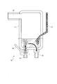
- a processing furnace 10 having a vacuum chamber 11 as shown in FIG. 1 can be used as the processing furnace.
- the processing furnace 10 includes a vacuum chamber 11, an exhaust unit 12 that discharges gas in the vacuum chamber 11 to the outside, a suction pipe 13 that sucks molten steel into the vacuum chamber 11, and a vacuum chamber 11 is provided with a discharge pipe 15 for discharging the molten steel in 11, and an element supply unit 17 for supplying a raw material (additive) to the molten steel in the vacuum chamber 11.
- the suction pipe 13 is provided with an inert gas introduction means 14 for introducing an inert gas (Ar gas in the present embodiment).
- the Al raw material in the secondary refining process, is supplied to the molten steel in the processing furnace, and then the Mn raw material and the Ti raw material are supplied. That is, the Al raw material is supplied to the molten steel in the vacuum chamber 11, and then, after the supplied Al raw material is melted and uniformly dispersed in the molten steel, the Mn raw material and the Ti raw material are supplied.
- the supply of the Mn raw material and the supply of the Ti raw material may be performed in this order or simultaneously.
- the Mn raw material is supplied after the Al raw material is supplied and the Al raw material is melted, the Mn raw material and the Al raw material coexist on the molten steel in the processing furnace. Is avoided. Therefore, it is possible to suppress the formation of composite oxide of Mn and Al (MnO ⁇ Al 2 O 3 ). That is, for example, MnO and Al 2 O 3 exist alone in the molten steel in the processing furnace, and even if MnO is reduced by the added Ti, a high-melting-point composite oxide of Al and Ti ( Al 2 O 3 .TiO X ) is not generated, and it is possible to suppress blockage of the molten steel path. This makes it possible to stably carry out the scheduled number of continuous castings.
- the oxygen in the molten steel when supplying the Al raw material to the molten steel may be 150 ppm or more in mass ratio.
- a composite oxide of Mn and Al (MnO.Al 2 O 3 ) is generated.
- Cheap the oxygen content in the molten steel is sufficiently reduced by supplying the Al material. It becomes possible to do.
- Mn raw material when Mn raw material is first supplied to molten steel having high oxygen in the molten steel, MnO is generated in the vacuum chamber 11, and Al composite material (MnO ⁇ Al) is added to the Al raw material. 2 O 3 ) may be generated.
- the Mn raw material after 30 seconds or more have passed since the Al raw material was supplied to the molten steel in the vacuum chamber 11. This is because the Al material can be reliably melted by passing 30 seconds or more after the Al material is supplied. Note that it is more preferable to supply the Mn raw material after 1 minute or more has passed since the Al raw material was supplied to the molten steel in the vacuum chamber 11.
- the Al raw material supply timing and the Mn raw material supply timing are set so that the Mn raw material and the Al raw material do not coexist on the molten steel in the vacuum chamber 11. And adjusting.
- oxygen may be blown in order to raise the temperature of the molten steel in the vacuum chamber 11.
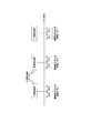
- oxygen blowing in order to suppress the oxidation of the supplied Ti, Al, Mn, and to suppress the formation of excessive Ti oxide, Al oxide, Mn oxide, Al raw material, Mn raw material It is preferable that the supply timing of the Ti raw material and the oxygen gas blowing timing be shifted by 1 minute or more. In other words, as shown in FIG.
- the molten steel whose component composition is adjusted as described above is supplied to a continuous casting apparatus, and the steel slab is continuously cast.
- the Al raw material is supplied to the molten steel in the vacuum chamber 11 with respect to the molten steel in the vacuum chamber 11.
- the Mn raw material is supplied to the molten steel in the vacuum tank 11, so that the Mn raw material and the Al raw material do not coexist on the molten steel, and Mn and Generation of Al composite oxide (MnO.Al 2 O 3 ) can be suppressed.
- the Al raw material, the Mn raw material, the Ti raw material supply timing and the oxygen gas blowing timing are shifted by 1 minute or more to obtain Al oxide, Mn oxide, Ti Excess generation of oxide can be suppressed, and inclusions can be further suppressed.
- the molten steel in the vacuum chamber 11 can be heated by blowing oxygen, it is not necessary to set the blowing temperature of the converter higher than necessary, and the energy cost can be reduced. it can.
- the Mn raw material and the Ti raw material are supplied in this order, that is, in the secondary refining step, the Al raw material and the Mn raw material are supplied. It is preferable to supply the molten steel in the order of Ti raw material. In this case, since the Ti raw material is supplied after the Mn raw material is supplied and the Mn raw material is melted, the coexistence of the Mn raw material and the Ti raw material is avoided on the molten steel in the processing furnace. Therefore, generation of a composite oxide of Mn and Ti (MnO ⁇ TiO x ) can also be suppressed.
- the composite oxide of Mn and Ti (MnO ⁇ TiO x ) is reduced by Al in the molten steel to produce a composite oxide of Al and Ti (Al 2 O 3 ⁇ TiO x ).
- Al composite oxide MnO.Al 2 O 3
- the Mn raw material is supplied to the molten steel in the vacuum chamber 11 in order to reliably melt the Mn raw material. Then, it is preferable to supply the Ti raw material after 30 seconds or longer, and it is more preferable to supply the Ti raw material after 1 minute or longer.
- the steel melting method according to the present embodiment is different from the first embodiment in the order of supplying the Al raw material, the Mn raw material, and the Ti raw material to the molten steel in the processing furnace in the secondary refining process, and Therefore, the description overlapping with the description of the first embodiment is omitted.
- the Al raw material and the Mn raw material are supplied to the molten steel in the processing furnace, and then the Ti raw material is supplied. That is, the Al raw material and the Mn raw material are supplied to the molten steel in the vacuum chamber 11, and then the Ti raw material is supplied after the supplied Mn raw material is melted and uniformly dispersed in the molten steel.
- the supply of the Al raw material and the supply of the Mn raw material may be performed in this order or simultaneously.
- the method for melting steel since the Ti raw material is supplied after the Mn raw material is supplied and the Mn raw material is melted, the coexistence of the Mn raw material and the Ti raw material on the molten steel in the processing furnace. Is avoided. Therefore, it is possible to suppress the formation of composite oxides of Mn and Ti (MnO ⁇ TiO X). That is, in the molten steel in the processing furnace, for example, MnO and TiO X exist alone, and even if MnO is reduced by Al contained in the molten steel, a high melting point composite oxide of Al and Ti ( Al 2 O 3 .TiO X ) is not generated, and it is possible to suppress blockage of the molten steel path. This makes it possible to stably carry out the scheduled number of continuous castings.
- the Ti raw material is preferably supplied after 30 seconds or more have passed since the Mn raw material was supplied to the molten steel in the vacuum chamber 11. This is because the Mn raw material can be reliably melted by allowing 30 seconds or more after the supply of the Mn raw material.
- the Ti raw material is preferably supplied after 1 minute or more has passed since the Mn raw material was supplied to the molten steel in the vacuum chamber 11.
- the molten steel whose component composition is adjusted as described above is supplied to a continuous casting apparatus, and the steel slab is continuously cast.
- Mn raw material is supplied to the molten steel in the vacuum chamber 11 with respect to the molten steel in the vacuum chamber 11.
- the Ti raw material is supplied to the molten steel in the vacuum tank 11, so that the Mn raw material and the Ti raw material do not coexist on the molten steel. Generation of Ti composite oxide (MnO.TiO x ) can be suppressed.
- the supply of the Al raw material and the supply of the Mn raw material are performed in this order, that is, in the secondary refining process, the Al raw material and the Mn raw material are supplied. It is preferable to supply the molten steel in the order of Ti raw material.
- both generation of a composite oxide of Mn and Al (MnO ⁇ Al 2 O 3 ) and generation of a composite oxide of Mn and Ti (MnO ⁇ TiO X ) are avoided. By doing so, it becomes possible to more reliably prevent the molten steel path from being blocked.
- the present invention is not limited to this, and can be appropriately changed without departing from the technical idea of the present invention.
- it has been described as using a processing furnace composed of a vacuum tank, but the present invention is not limited to this, and the present invention is applied to any processing furnace that performs secondary refining. Can do.
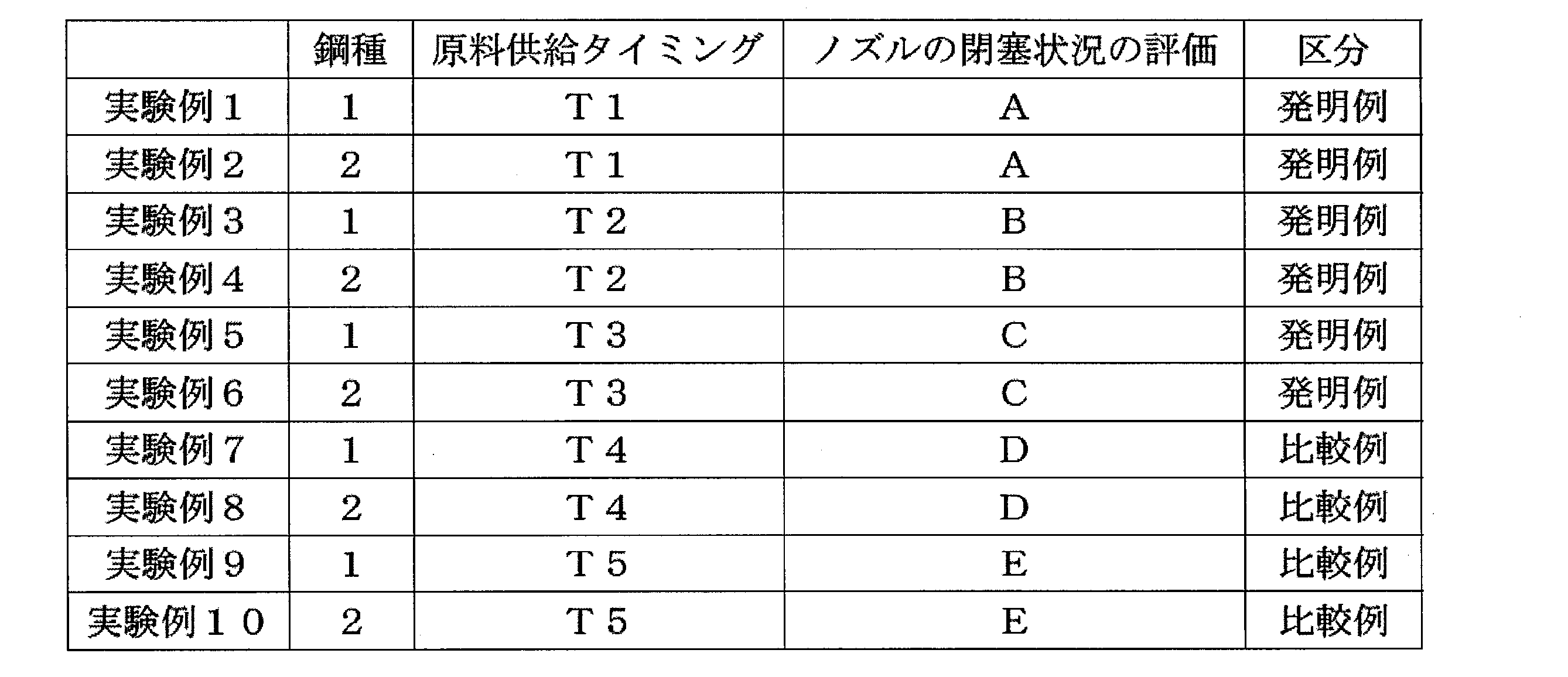
- Table 2 shows the supply timing of the Al raw material, the Mn raw material, and the Ti raw material in the secondary refining process.
- the nozzle clogging condition when casting eight consecutive times was evaluated according to the following criteria.
- “The case where the tendency of nozzle clogging was observed” means that the ratio of the nozzle cross-sectional area including the deposit after completion of casting to the nozzle cross-sectional area without the deposit before the start of casting is 95% or less.
- the “case in which nozzle clogging has occurred” means a case where the ratio of the nozzle cross-sectional area including deposits after completion of casting to the nozzle cross-sectional area without deposits before starting casting is 75% or less.
- processing furnace 11 vacuum chamber 12: exhaust part 13: suction pipe 14: inert gas introduction means 15: discharge pipe 17: element supply part
Landscapes
- Chemical & Material Sciences (AREA)
- Engineering & Computer Science (AREA)
- Materials Engineering (AREA)
- Metallurgy (AREA)
- Organic Chemistry (AREA)
- Mechanical Engineering (AREA)
- Treatment Of Steel In Its Molten State (AREA)
- Carbon Steel Or Casting Steel Manufacturing (AREA)
Abstract
Description
本願は、2017年2月21日に、日本に出願された特願2017-029645号に基づき優先権を主張し、その内容をここに援用する。
そこで、従来より、ノズルの加熱やノズル等の溶鋼経路へのArガスの吹き込みを実施することにより、アルミナや地金の付着を抑制する技術が実施されている(例えば、特許文献1~4参照)。
(1)本発明の一態様は、MnとTiを含有するAlキルド鋼からなる鋼の溶製方法であって、転炉において一次精錬を行う一次精錬工程と、前記転炉から処理炉に溶鋼を移送し、前記処理炉において、前記溶鋼にAl原料、Mn原料、及びTi原料を供給して成分組成を調整する二次精錬工程と、を備え、前記二次精錬工程では、前記処理炉内の前記溶鋼に対し、前記Al原料の供給を行い、その後、前記Mn原料の供給及び前記Ti原料の供給をこの順又は同時に行う、又は、前記処理炉内の前記溶鋼に対し、前記Al原料の供給及び前記Mn原料の供給をこの順又は同時に行い、その後、前記Ti原料の供給を行う。
(3)上記(2)に記載の鋼の溶製方法では、前記Al原料の供給を完了してから30秒以上経過後に前記Mn原料の供給を開始してもよい。
(4)上記(2)又は(3)に記載の鋼の溶製方法では、前記二次精錬工程において、前記Al原料の供給を行い、その後、前記Mn原料の供給及び前記Ti原料の供給をこの順に行ってもよい。
(5)上記(4)に記載の鋼の溶製方法では、前記Mn原料の供給を完了してから30秒以上経過後に前記Ti原料の供給を開始してもよい。
(6)上記(2)~(5)のいずれか一項に記載の鋼の溶製方法では、前記Al原料を前記溶鋼に供給する際の前記溶鋼中の酸素が質量比で150ppm以上であってもよい。
(8)上記(7)に記載の鋼の溶製方法では、前記Mn原料の供給を完了してから30秒以上経過後に前記Ti原料の供給を開始してもよい。
(10)上記(9)に記載の鋼の溶製方法では、前記Al原料の供給の開始1分前から前記Al原料の供給の終了1分後までの期間、前記Mn原料の供給の開始1分前から前記Mn原料の供給の終了1分後までの期間、及び、前記Ti原料の供給の開始1分前から、前記Ti原料の供給の終了1分後までの期間においては、前記酸素の吹き込みを行わなくてもよい。
(11)上記(1)~(10)のいずれか一項に記載の鋼の溶製方法では、前記二次精錬工程の完了時の溶鋼が、質量比で、C:0.0013%以上0.040%以下、Al:0.01%以上0.10%以下、Mn:0.20%以上3.00%以下、Ti:0.004%以上0.100%以下、を含有してもよい。
上記(4)に記載の鋼の溶製方法によれば、処理炉内の溶鋼上において、Mn原料とAl原料との共存が回避されるだけでなく、Mn原料とTi原料との共存も回避されるため、MnとAlの複合酸化物(MnO・Al2O3)、及び、MnとTiの複合酸化物(MnO・TiOX)の生成を抑制することができる。従って、溶鋼経路の閉塞を更に抑制することが可能となる。
上記(5)に記載の鋼の溶製方法によれば、供給したMn原料が溶鋼中に溶解して均一に分散した状態でTi原料が供給される。これにより、処理炉内の溶鋼上において、Mn原料とTi原料との共存がより確実に回避され、MnとTiの複合酸化物(MnO・TiOX)の生成を更に抑制することが可能となる。
また、(6)に記載された方法のように、溶鋼中酸素が質量比で150ppm以上の高い状態であっても、上述の溶製方法によれば、Al原料を供給してAl原料が溶融した後にMn原料を供給するため、Al原料の供給により溶鋼中の酸素含有量を十分に低減することが可能となるため、MnとAlの複合酸化物(MnO・Al2O3)の生成を抑制することが可能となる。従って、Mn及びTiを含むAlキルド鋼を連続鋳造した場合であっても、溶鋼経路の閉塞を抑制でき、安定した鋳造を行うことが可能となる。
上記(8)に記載の鋼の溶製方法によれば、供給したMn原料が溶鋼中に溶解して均一に分散した状態でTi原料が供給される。これにより、処理炉内の溶鋼上においてMn原料とTi原料との共存がより確実に回避され、MnとTiの複合酸化物(MnO・TiOX)の生成を更に抑制することが可能となる。
上記(10)に記載の鋼の溶製方法によれば、酸素吹き込み直後の酸素濃度の高い溶鋼にTi,Al,Mnの供給と同時に酸素の吹き込みを実施しないため、Alの酸化物、Mnの酸化物、及びTiの酸化物が過剰に生成してしまうことを防ぐことができる。なお、従来は、処理炉において酸素の吹き込みを行うと介在物が増加する懸念があるため、転炉の吹止温度を高く設定し、処理炉における酸素の吹き込みの実施を制限していたが、上述のように酸素の吹き込みのタイミングを適正化することで、処理炉において溶鋼温度を上昇させることが可能となる。よって、転炉の吹止温度を必要以上に高く設定する必要はなく、エネルギーコストの削減を図ることもできる。
上記(11)に記載の鋼の溶製方法によれば、二次精錬工程の完了時に、質量比で、C:0.0013% 以上%以上0.040%以下、Al:0.01%以上0.10%以下、Mn:0.20%以上3.00%以下、Ti:0.004%以上0.100%以下、を含有する溶鋼を得ることができる。
また、MnとAlの複合酸化物(MnO・Al2O3)、及び、MnとTiの複合酸化物(MnO・TiOX)は融点が低く、溶鋼中では固液二相共存状態又は液相状態の介在物として存在するが、これらの複合酸化物は、MnOがAlやTiにより還元されてAlとTiの複合酸化物(Al2O3・TiOX)となると、融点が高くなり、溶鋼経路の閉塞の要因となる、との知見を得た。
以下、本発明の第一実施形態に係る鋼の溶製方法について説明する。
本実施形態に係る鋼の溶製方法は、MnとTiを含有するAlキルド鋼からなる鋼の溶製方法であり、一次精錬工程と二次精錬工程とを有する。
従って、二次精錬工程の完了時の溶鋼は、質量比で、C:0.0013%以上0.040%以下、Al:0.01%以上0.10%以下、Mn:0.20%以上3.00%以下、Ti:0.004%以上0.100%以下、を含有するように成分が調整される。
好ましくは、二次精錬工程の完了時の溶鋼は、質量比で、C:0.0032%以上0.040%以下、Al:0.01%以上0.10%以下、Mn:0.20%以上3.00%以下、Ti:0.004%以上0.100%以下、を含有するように成分が調整される。
この処理炉10は、図1に示すように、真空槽11と、真空槽11内のガスを外部に排出する排気部12と、溶鋼を真空槽11内に吸い上げる吸上管13と、真空槽11内の溶鋼を排出する排出管15と、真空槽11内の溶鋼に対して原料(添加材)を供給する元素供給部17と、を備えている。なお、吸上管13には、不活性ガス(本実施形態ではArガス)を導入する不活性ガス導入手段14が配設されている。
尚、本実施形態に係る鋼の溶製方法においては、Mn原料の供給とTi原料の供給は、この順に行ってもよく、同時に行ってもよい。
すなわち、処理炉内の溶鋼中には、例えばMnOやAl2O3が単独で存在することになり、添加されるTiによってMnOが還元されても、高融点のAlとTiの複合酸化物(Al2O3・TiOX)が生成せず、溶鋼経路の閉塞を抑制することが可能となる。これにより、予定した連々鋳回数を安定して実施することが可能となる。
通常、酸素含有量が質量比で150ppm以上である溶鋼に対してAl原料とMn原料を用いて二次精錬を行うと、MnとAlの複合酸化物(MnO・Al2O3)が生成しやすい。しかしながら、本実施形態に係る鋼の溶製方法によれば、Al原料を供給してAl原料が溶融した後にMn原料を供給するため、Al原料の供給により溶鋼中の酸素含有量を十分に低減することが可能となる。従って、Al原料を溶鋼に供給する際の溶鋼の酸素含有量が質量比で150ppm以上であっても、MnとAlの複合酸化物(MnO・Al2O3)の生成を抑制することが可能となる。従って、Mn及びTiを含むAlキルド鋼を連続鋳造した場合であっても、溶鋼経路の閉塞を抑制でき、安定した鋳造を行うことが可能となる。
なお、Al原料を真空槽11内の溶鋼に供給してから1分以上経過した後にMn原料を供給することが更に好ましい。
酸素の吹き込みを行う場合には、供給したTi、Al、Mnの酸化を抑制し、過剰なTi酸化物、Al酸化物、Mn酸化物が生成することを抑制するために、Al原料、Mn原料、Ti原料の供給タイミングと酸素ガスの吹き込みタイミングとを1分以上ずらすことが好ましい。
換言すると、図2に示すように、Al原料供給の開始1分前からAl原料供給の終了1分後までの期間、Mn原料供給の開始1分前からMn原料供給の終了1分後までの期間、及び、Ti原料供給の開始1分前からTi原料供給の終了1分後までの期間においては、酸素の吹き込みを実施しないことが好ましい。
これにより、その後にTiを添加しても、高融点のAlとTiの複合酸化物(Al2O3・TiOX)の生成が抑制され、溶鋼経路の閉塞が発生しにくくなり、予定された連々鋳回数を安定して実施することが可能となる。また、介在物の巻き込みを抑制することができ、高品質な鋳片を製造することができる。
また、酸素の吹き込みを行うことにより、真空槽11内の溶鋼を昇温することができることから、転炉の吹止温度を必要以上に高く設定する必要はなく、エネルギーコストの削減を図ることができる。
この場合、Mn原料を供給してMn原料が溶融した後にTi原料が供給されるため、処理炉内の溶鋼上において、Mn原料とTi原料との共存が回避される。従って、MnとTiの複合酸化物(MnO・TiOX)の生成も抑制することができる。
このMnとTiの複合酸化物(MnO・TiOX)は、溶鋼中のAlによって還元されることにより、AlとTiの複合酸化物(Al2O3・TiOX)を生成するため、MnとAlの複合酸化物(MnO・Al2O3)と同様にノズル等の溶鋼経路の内壁に付着し、溶鋼経路の閉塞の原因となる。
従って、MnとAlの複合酸化物(MnO・Al2O3)の生成とMnとTiの複合酸化物(MnO・TiOX)の生成を共に回避することにより、溶鋼経路の閉塞をより確実に防ぐことが可能となる。
以下、本発明の第二実施形態に係る鋼の溶製方法について説明する。
本実施形態に係る鋼の溶製方法は、二次精錬工程において、処理炉内の溶鋼に対しAl原料、Mn原料、及びTi原料を供給する順序が第一実施形態と異なるものであり、以下においては第一実施形態の説明と重複する説明は省略する。
尚、本実施形態に係る鋼の溶製方法においては、Al原料の供給とMn原料の供給は、この順に行ってもよく、同時に行ってもよい。
すなわち、処理炉内の溶鋼中には、例えばMnOやTiOXが単独で存在することになり、溶鋼中に含まれるAlによってMnOが還元されても、高融点のAlとTiの複合酸化物(Al2O3・TiOX)が生成せず、溶鋼経路の閉塞を抑制することが可能となる。これにより、予定した連々鋳回数を安定して実施することが可能となる。
好ましくは、Mn原料を真空槽11内の溶鋼に供給してから1分以上経過した後にTi原料を供給することが好ましい。
これにより、高融点のAlとTiの複合酸化物(Al2O3・TiOX)の生成が抑制され、溶鋼経路の閉塞が発生しにくくなり、予定された連々鋳回数を安定して実施することが可能となる。また、介在物の巻き込みを抑制することができ、高品質な鋳片を製造することができる。
例えば、本実施形態では、真空槽で構成された処理炉を用いるものとして説明したが、これに限定されることはなく、二次精錬を実施する処理炉であれば、本発明を適用することができる。
表1に示す範囲の組成の溶鋼を用いて、垂直曲げ型連続鋳造機(以下、連鋳機)により鋳造してスラブを製造した。なお、表1の鋼種2は極低炭材であり、転炉では未脱酸出鋼しており、RHで脱炭処理後、Al原料の供給、及び、Mn原料の供給を行う前の溶鋼中酸素は約500ppmであった。


A:8連々鋳において、いずれのチャージでもノズル閉塞の傾向が見られなかったケース
B:8連々鋳において、1チャージのみでノズル閉塞の傾向が見られたケース
C:8連々鋳において、2チャージのみでノズル閉塞の傾向が見られたケース
D:8連々鋳において、3チャージ以上でノズル閉塞の傾向が見られたケース(比較例)
E:8連々鋳において、ノズル閉塞が発生したケース(比較例)
「ノズル閉塞の傾向が見られたケース」とは、鋳造開始前の付着物のないノズル断面積に対する、鋳造完了後の付着物を含むノズル断面積の割合が95%以下となったケースを意味し、「ノズル閉塞が発生したケース」とは、鋳造開始前の付着物のないノズル断面積に対する鋳造完了後の付着物を含むノズル断面積の割合が75%以下となったケースを意味する。
11:真空槽
12:排気部
13:吸上管
14:不活性ガス導入手段
15:排出管
17:元素供給部
Claims (11)
- MnとTiを含有するAlキルド鋼からなる鋼の溶製方法であって、
転炉において一次精錬を行う一次精錬工程と、
前記転炉から処理炉に溶鋼を移送し、前記処理炉において、前記溶鋼にAl原料、Mn原料、及びTi原料を供給して成分組成を調整する二次精錬工程と、
を備え、
前記二次精錬工程では、
前記処理炉内の前記溶鋼に対し、前記Al原料の供給を行い、その後、前記Mn原料の供給及び前記Ti原料の供給をこの順又は同時に行う、又は、
前記処理炉内の前記溶鋼に対し、前記Al原料の供給及び前記Mn原料の供給をこの順又は同時に行い、その後、前記Ti原料の供給を行う
ことを特徴とする鋼の溶製方法。 - 前記二次精錬工程では、
前記Al原料の供給を行い、その後、前記Mn原料の供給及び前記Ti原料の供給をこの順又は同時に行う
ことを特徴とする請求項1に記載の鋼の溶製方法。 - 前記Al原料の供給を完了してから30秒以上経過後に前記Mn原料の供給を開始する
ことを特徴とする請求項2に記載の鋼の溶製方法。 - 前記二次精錬工程では、
前記Al原料の供給を行い、その後、前記Mn原料の供給及び前記Ti原料の供給をこの順に行う
ことを特徴とする請求項2又は3に記載の鋼の溶製方法。 - 前記Mn原料の供給を完了してから30秒以上経過後に前記Ti原料の供給を開始する
ことを特徴とする請求項4に記載の鋼の溶製方法。 - 前記Al原料を前記溶鋼に供給する際の前記溶鋼中の酸素が質量比で150ppm以上である
ことを特徴とする請求項2~5のいずれか一項に記載の鋼の溶製方法。 - 前記二次精錬工程では、
前記Al原料の供給及び前記Mn原料の供給をこの順又は同時に行い、その後、前記Ti原料の供給を行う
ことを特徴とする請求項1に記載の鋼の溶製方法。 - 前記Mn原料の供給を完了してから30秒以上経過後に前記Ti原料の供給を開始する
ことを特徴とする請求項7に記載の鋼の溶製方法。 - 前記二次精錬工程において酸素の吹き込みを行う
ことを特徴とする請求項1~8のいずれか一項に記載の鋼の溶製方法。 - 前記Al原料の供給の開始1分前から前記Al原料の供給の終了1分後までの期間、前記Mn原料の供給の開始1分前から前記Mn原料の供給の終了1分後までの期間、及び、前記Ti原料の供給の開始1分前から、前記Ti原料の供給の終了1分後までの期間においては、前記酸素の吹き込みを行わない
ことを特徴とする請求項9に記載の鋼の溶製方法。 - 前記二次精錬工程の完了時の前記溶鋼が、質量比で、
C:0.0013%以上0.040%以下、
Al:0.01%以上0.10%以下、
Mn:0.20%以上3.00%以下、
Ti:0.004%以上0.100%以下、
を含有する
ことを特徴とする請求項1~10のいずれか一項に記載の鋼の溶製方法。
Priority Applications (3)
| Application Number | Priority Date | Filing Date | Title |
|---|---|---|---|
| JP2019501286A JPWO2018155334A1 (ja) | 2017-02-21 | 2018-02-16 | 鋼の溶製方法 |
| KR1020197006496A KR20190039744A (ko) | 2017-02-21 | 2018-02-16 | 강의 용제 방법 |
| CN201880003473.3A CN109689897A (zh) | 2017-02-21 | 2018-02-16 | 钢的熔炼方法 |
Applications Claiming Priority (2)
| Application Number | Priority Date | Filing Date | Title |
|---|---|---|---|
| JP2017-029645 | 2017-02-21 | ||
| JP2017029645 | 2017-02-21 |
Publications (1)
| Publication Number | Publication Date |
|---|---|
| WO2018155334A1 true WO2018155334A1 (ja) | 2018-08-30 |
Family
ID=63252706
Family Applications (1)
| Application Number | Title | Priority Date | Filing Date |
|---|---|---|---|
| PCT/JP2018/005473 Ceased WO2018155334A1 (ja) | 2017-02-21 | 2018-02-16 | 鋼の溶製方法 |
Country Status (5)
| Country | Link |
|---|---|
| JP (1) | JPWO2018155334A1 (ja) |
| KR (1) | KR20190039744A (ja) |
| CN (1) | CN109689897A (ja) |
| TW (1) | TWI654042B (ja) |
| WO (1) | WO2018155334A1 (ja) |
Families Citing this family (1)
| Publication number | Priority date | Publication date | Assignee | Title |
|---|---|---|---|---|
| US10727958B2 (en) | 2018-11-27 | 2020-07-28 | Samsung Electronics Co., Ltd. | Method and device for measuring antenna reflection coefficient |
Citations (4)
| Publication number | Priority date | Publication date | Assignee | Title |
|---|---|---|---|---|
| JPS61284517A (ja) * | 1985-06-10 | 1986-12-15 | Nippon Steel Corp | 低炭素鋼材の製造方法 |
| JP2002030330A (ja) * | 1999-12-17 | 2002-01-31 | Nkk Corp | 真空精錬炉における溶鋼の加熱方法 |
| JP2013095947A (ja) * | 2011-10-31 | 2013-05-20 | Jfe Steel Corp | 高清浄度鋼の製造方法 |
| JP2014025111A (ja) * | 2012-07-27 | 2014-02-06 | Jfe Steel Corp | 高清浄度鋼の製造方法 |
Family Cites Families (15)
| Publication number | Priority date | Publication date | Assignee | Title |
|---|---|---|---|---|
| TW408184B (en) * | 1997-09-29 | 2000-10-11 | Kawasaki Steel Co | Manufacturing method for producing Titanium killed steel with smooth surface texture |
| JP2002336942A (ja) | 2001-05-16 | 2002-11-26 | Nkk Corp | 連続鋳造用浸漬ノズルおよび連続鋳造方法 |
| JP3852396B2 (ja) * | 2002-11-07 | 2006-11-29 | 住友金属工業株式会社 | 薄鋼板および薄鋼板用溶鋼の脱酸方法 |
| JP2004243407A (ja) | 2003-02-17 | 2004-09-02 | Sumitomo Metal Ind Ltd | Mg合金溶湯の連続鋳造方法 |
| JP4687103B2 (ja) * | 2004-12-28 | 2011-05-25 | Jfeスチール株式会社 | 低炭素アルミキルド鋼の溶製方法 |
| JP4734201B2 (ja) | 2006-08-31 | 2011-07-27 | 新日本製鐵株式会社 | 連続鋳造方法 |
| TWI391500B (zh) | 2008-08-06 | 2013-04-01 | Posco | 環保無鉛之快削鋼及其製作方法 |
| JP4585606B2 (ja) | 2008-12-26 | 2010-11-24 | 新日本製鐵株式会社 | 連続鋳造方法及びノズル加熱装置 |
| JP5768405B2 (ja) * | 2010-03-02 | 2015-08-26 | 新日鐵住金株式会社 | 鋼板およびその製造方法 |
| JP5451591B2 (ja) * | 2010-12-27 | 2014-03-26 | 株式会社神戸製鋼所 | 二次精錬方法 |
| JP5158272B2 (ja) * | 2011-03-10 | 2013-03-06 | 新日鐵住金株式会社 | 伸びフランジ性と曲げ加工性に優れた高強度鋼板およびその溶鋼の溶製方法 |
| WO2013018629A1 (ja) | 2011-07-29 | 2013-02-07 | 新日鐵住金株式会社 | 高Siオーステナイト系ステンレス鋼の製造方法 |
| CN103695774B (zh) | 2013-12-12 | 2016-04-13 | 山西新泰钢铁有限公司 | 一种含钛和硼热轧低硬度的高强度紧固件用钢及其生产方法 |
| CN103741006B (zh) | 2014-01-09 | 2016-01-13 | 张家港浦项不锈钢有限公司 | 一种含Ti低氮不锈钢的制备方法 |
| CN103924157B (zh) | 2014-04-01 | 2016-01-20 | 甘肃酒钢集团宏兴钢铁股份有限公司 | 一种含钛铁素体不锈钢的冶炼方法 |
-
2018
- 2018-02-14 TW TW107105625A patent/TWI654042B/zh not_active IP Right Cessation
- 2018-02-16 CN CN201880003473.3A patent/CN109689897A/zh active Pending
- 2018-02-16 KR KR1020197006496A patent/KR20190039744A/ko not_active Withdrawn
- 2018-02-16 WO PCT/JP2018/005473 patent/WO2018155334A1/ja not_active Ceased
- 2018-02-16 JP JP2019501286A patent/JPWO2018155334A1/ja active Pending
Patent Citations (4)
| Publication number | Priority date | Publication date | Assignee | Title |
|---|---|---|---|---|
| JPS61284517A (ja) * | 1985-06-10 | 1986-12-15 | Nippon Steel Corp | 低炭素鋼材の製造方法 |
| JP2002030330A (ja) * | 1999-12-17 | 2002-01-31 | Nkk Corp | 真空精錬炉における溶鋼の加熱方法 |
| JP2013095947A (ja) * | 2011-10-31 | 2013-05-20 | Jfe Steel Corp | 高清浄度鋼の製造方法 |
| JP2014025111A (ja) * | 2012-07-27 | 2014-02-06 | Jfe Steel Corp | 高清浄度鋼の製造方法 |
Also Published As
| Publication number | Publication date |
|---|---|
| TWI654042B (zh) | 2019-03-21 |
| JPWO2018155334A1 (ja) | 2019-06-27 |
| KR20190039744A (ko) | 2019-04-15 |
| CN109689897A (zh) | 2019-04-26 |
| TW201831245A (zh) | 2018-09-01 |
Similar Documents
| Publication | Publication Date | Title |
|---|---|---|
| CN111206137B (zh) | 一种高钛铁水生产高牌号无取向硅钢中低钛含量稳定控制的方法 | |
| CN101553583B (zh) | 超低硫低氮高纯度钢的熔炼方法 | |
| JP5891826B2 (ja) | 溶鋼の脱硫方法 | |
| WO2018216660A1 (ja) | 高マンガン鋼の溶製方法 | |
| JP4193784B2 (ja) | Ti含有ステンレス鋼の製造方法 | |
| JPWO2018155334A1 (ja) | 鋼の溶製方法 | |
| JP7010094B2 (ja) | ステンレス鋳片の製造方法 | |
| CN109280740B (zh) | 一种lf精炼炉到位黄白渣的工艺方法 | |
| JPH04274866A (ja) | タンディッシュ内添加用フラックス | |
| JP4534734B2 (ja) | 低炭素高マンガン鋼の溶製方法 | |
| JP6953714B2 (ja) | 溶鋼の昇温方法 | |
| JP4360270B2 (ja) | 溶鋼の精錬方法 | |
| JP5047477B2 (ja) | 高Al鋼の二次精錬方法 | |
| CN113957197B (zh) | 一种减少轴承钢中大尺寸夹杂物的转炉出钢冶金工艺 | |
| JP6737304B2 (ja) | 鋼の溶製方法及び連続鋳造方法 | |
| JP4301112B2 (ja) | タンディッシュを熱間繰り返し使用する連続鋳造方法 | |
| JP7067280B2 (ja) | 溶鋼の取鍋精錬方法 | |
| WO2021106484A1 (ja) | 溶鋼の鋳造方法、連続鋳造鋳片の製造方法及び軸受用鋼材の製造方法 | |
| JP5326201B2 (ja) | アルミキルド鋼の溶製方法 | |
| JP3813902B2 (ja) | タンディッシュの連続使用方法 | |
| JP7067279B2 (ja) | 溶鋼の取鍋精錬方法 | |
| KR100434735B1 (ko) | 인함유 극저탄소강 제조방법 | |
| JP4025713B2 (ja) | 溶銑の脱燐精錬方法 | |
| JP3257263B2 (ja) | 高清浄度溶鋼の製造方法 | |
| JPH11279623A (ja) | 精錬容器の耐火物溶損を抑えた製造性の良い高Al含有フェライト系ステンレス鋼の溶製方法 |
Legal Events
| Date | Code | Title | Description |
|---|---|---|---|
| 121 | Ep: the epo has been informed by wipo that ep was designated in this application |
Ref document number: 18756775 Country of ref document: EP Kind code of ref document: A1 |
|
| ENP | Entry into the national phase |
Ref document number: 2019501286 Country of ref document: JP Kind code of ref document: A |
|
| ENP | Entry into the national phase |
Ref document number: 20197006496 Country of ref document: KR Kind code of ref document: A |
|
| NENP | Non-entry into the national phase |
Ref country code: DE |
|
| 122 | Ep: pct application non-entry in european phase |
Ref document number: 18756775 Country of ref document: EP Kind code of ref document: A1 |