WO2018092680A1 - Dispositif à semiconducteur - Google Patents
Dispositif à semiconducteur Download PDFInfo
- Publication number
- WO2018092680A1 WO2018092680A1 PCT/JP2017/040490 JP2017040490W WO2018092680A1 WO 2018092680 A1 WO2018092680 A1 WO 2018092680A1 JP 2017040490 W JP2017040490 W JP 2017040490W WO 2018092680 A1 WO2018092680 A1 WO 2018092680A1
- Authority
- WO
- WIPO (PCT)
- Prior art keywords
- trench
- insulating film
- gate insulating
- gate
- semiconductor device
- Prior art date
Links
- 239000004065 semiconductor Substances 0.000 title claims abstract description 95
- 239000010410 layer Substances 0.000 claims description 132
- 239000002344 surface layer Substances 0.000 claims description 4
- 238000009413 insulation Methods 0.000 abstract 3
- 238000004088 simulation Methods 0.000 description 17
- 239000000758 substrate Substances 0.000 description 13
- 210000000746 body region Anatomy 0.000 description 8
- VYPSYNLAJGMNEJ-UHFFFAOYSA-N Silicium dioxide Chemical compound O=[Si]=O VYPSYNLAJGMNEJ-UHFFFAOYSA-N 0.000 description 6
- 229910052814 silicon oxide Inorganic materials 0.000 description 6
- 230000007423 decrease Effects 0.000 description 5
- 239000000463 material Substances 0.000 description 4
- 230000000694 effects Effects 0.000 description 3
- 239000011229 interlayer Substances 0.000 description 3
- 239000005380 borophosphosilicate glass Substances 0.000 description 2
- 239000012535 impurity Substances 0.000 description 2
- 238000000034 method Methods 0.000 description 2
- 230000004048 modification Effects 0.000 description 2
- 238000012986 modification Methods 0.000 description 2
- 230000008569 process Effects 0.000 description 2
- 230000007480 spreading Effects 0.000 description 2
- 230000007704 transition Effects 0.000 description 2
- 229910004298 SiO 2 Inorganic materials 0.000 description 1
- 239000000969 carrier Substances 0.000 description 1
- 230000015556 catabolic process Effects 0.000 description 1
- 238000002347 injection Methods 0.000 description 1
- 239000007924 injection Substances 0.000 description 1
- 238000004519 manufacturing process Methods 0.000 description 1
- 229910052710 silicon Inorganic materials 0.000 description 1
- 239000010703 silicon Substances 0.000 description 1
Images


Classifications
-
- H—ELECTRICITY
- H01—ELECTRIC ELEMENTS
- H01L—SEMICONDUCTOR DEVICES NOT COVERED BY CLASS H10
- H01L29/00—Semiconductor devices specially adapted for rectifying, amplifying, oscillating or switching and having potential barriers; Capacitors or resistors having potential barriers, e.g. a PN-junction depletion layer or carrier concentration layer; Details of semiconductor bodies or of electrodes thereof ; Multistep manufacturing processes therefor
- H01L29/66—Types of semiconductor device ; Multistep manufacturing processes therefor
- H01L29/68—Types of semiconductor device ; Multistep manufacturing processes therefor controllable by only the electric current supplied, or only the electric potential applied, to an electrode which does not carry the current to be rectified, amplified or switched
- H01L29/70—Bipolar devices
- H01L29/72—Transistor-type devices, i.e. able to continuously respond to applied control signals
- H01L29/739—Transistor-type devices, i.e. able to continuously respond to applied control signals controlled by field-effect, e.g. bipolar static induction transistors [BSIT]
- H01L29/7393—Insulated gate bipolar mode transistors, i.e. IGBT; IGT; COMFET
- H01L29/7395—Vertical transistors, e.g. vertical IGBT
- H01L29/7396—Vertical transistors, e.g. vertical IGBT with a non planar surface, e.g. with a non planar gate or with a trench or recess or pillar in the surface of the emitter, base or collector region for improving current density or short circuiting the emitter and base regions
- H01L29/7397—Vertical transistors, e.g. vertical IGBT with a non planar surface, e.g. with a non planar gate or with a trench or recess or pillar in the surface of the emitter, base or collector region for improving current density or short circuiting the emitter and base regions and a gate structure lying on a slanted or vertical surface or formed in a groove, e.g. trench gate IGBT
-
- H—ELECTRICITY
- H01—ELECTRIC ELEMENTS
- H01L—SEMICONDUCTOR DEVICES NOT COVERED BY CLASS H10
- H01L29/00—Semiconductor devices specially adapted for rectifying, amplifying, oscillating or switching and having potential barriers; Capacitors or resistors having potential barriers, e.g. a PN-junction depletion layer or carrier concentration layer; Details of semiconductor bodies or of electrodes thereof ; Multistep manufacturing processes therefor
- H01L29/02—Semiconductor bodies ; Multistep manufacturing processes therefor
- H01L29/06—Semiconductor bodies ; Multistep manufacturing processes therefor characterised by their shape; characterised by the shapes, relative sizes, or dispositions of the semiconductor regions ; characterised by the concentration or distribution of impurities within semiconductor regions
- H01L29/08—Semiconductor bodies ; Multistep manufacturing processes therefor characterised by their shape; characterised by the shapes, relative sizes, or dispositions of the semiconductor regions ; characterised by the concentration or distribution of impurities within semiconductor regions with semiconductor regions connected to an electrode carrying current to be rectified, amplified or switched and such electrode being part of a semiconductor device which comprises three or more electrodes
- H01L29/0804—Emitter regions of bipolar transistors
-
- H—ELECTRICITY
- H01—ELECTRIC ELEMENTS
- H01L—SEMICONDUCTOR DEVICES NOT COVERED BY CLASS H10
- H01L29/00—Semiconductor devices specially adapted for rectifying, amplifying, oscillating or switching and having potential barriers; Capacitors or resistors having potential barriers, e.g. a PN-junction depletion layer or carrier concentration layer; Details of semiconductor bodies or of electrodes thereof ; Multistep manufacturing processes therefor
- H01L29/02—Semiconductor bodies ; Multistep manufacturing processes therefor
- H01L29/06—Semiconductor bodies ; Multistep manufacturing processes therefor characterised by their shape; characterised by the shapes, relative sizes, or dispositions of the semiconductor regions ; characterised by the concentration or distribution of impurities within semiconductor regions
- H01L29/08—Semiconductor bodies ; Multistep manufacturing processes therefor characterised by their shape; characterised by the shapes, relative sizes, or dispositions of the semiconductor regions ; characterised by the concentration or distribution of impurities within semiconductor regions with semiconductor regions connected to an electrode carrying current to be rectified, amplified or switched and such electrode being part of a semiconductor device which comprises three or more electrodes
- H01L29/0821—Collector regions of bipolar transistors
-
- H—ELECTRICITY
- H01—ELECTRIC ELEMENTS
- H01L—SEMICONDUCTOR DEVICES NOT COVERED BY CLASS H10
- H01L29/00—Semiconductor devices specially adapted for rectifying, amplifying, oscillating or switching and having potential barriers; Capacitors or resistors having potential barriers, e.g. a PN-junction depletion layer or carrier concentration layer; Details of semiconductor bodies or of electrodes thereof ; Multistep manufacturing processes therefor
- H01L29/02—Semiconductor bodies ; Multistep manufacturing processes therefor
- H01L29/06—Semiconductor bodies ; Multistep manufacturing processes therefor characterised by their shape; characterised by the shapes, relative sizes, or dispositions of the semiconductor regions ; characterised by the concentration or distribution of impurities within semiconductor regions
- H01L29/10—Semiconductor bodies ; Multistep manufacturing processes therefor characterised by their shape; characterised by the shapes, relative sizes, or dispositions of the semiconductor regions ; characterised by the concentration or distribution of impurities within semiconductor regions with semiconductor regions connected to an electrode not carrying current to be rectified, amplified or switched and such electrode being part of a semiconductor device which comprises three or more electrodes
- H01L29/1004—Base region of bipolar transistors
-
- H—ELECTRICITY
- H01—ELECTRIC ELEMENTS
- H01L—SEMICONDUCTOR DEVICES NOT COVERED BY CLASS H10
- H01L29/00—Semiconductor devices specially adapted for rectifying, amplifying, oscillating or switching and having potential barriers; Capacitors or resistors having potential barriers, e.g. a PN-junction depletion layer or carrier concentration layer; Details of semiconductor bodies or of electrodes thereof ; Multistep manufacturing processes therefor
- H01L29/40—Electrodes ; Multistep manufacturing processes therefor
- H01L29/402—Field plates
- H01L29/407—Recessed field plates, e.g. trench field plates, buried field plates
-
- H—ELECTRICITY
- H01—ELECTRIC ELEMENTS
- H01L—SEMICONDUCTOR DEVICES NOT COVERED BY CLASS H10
- H01L29/00—Semiconductor devices specially adapted for rectifying, amplifying, oscillating or switching and having potential barriers; Capacitors or resistors having potential barriers, e.g. a PN-junction depletion layer or carrier concentration layer; Details of semiconductor bodies or of electrodes thereof ; Multistep manufacturing processes therefor
- H01L29/40—Electrodes ; Multistep manufacturing processes therefor
- H01L29/41—Electrodes ; Multistep manufacturing processes therefor characterised by their shape, relative sizes or dispositions
- H01L29/417—Electrodes ; Multistep manufacturing processes therefor characterised by their shape, relative sizes or dispositions carrying the current to be rectified, amplified or switched
- H01L29/41708—Emitter or collector electrodes for bipolar transistors
-
- H—ELECTRICITY
- H01—ELECTRIC ELEMENTS
- H01L—SEMICONDUCTOR DEVICES NOT COVERED BY CLASS H10
- H01L29/00—Semiconductor devices specially adapted for rectifying, amplifying, oscillating or switching and having potential barriers; Capacitors or resistors having potential barriers, e.g. a PN-junction depletion layer or carrier concentration layer; Details of semiconductor bodies or of electrodes thereof ; Multistep manufacturing processes therefor
- H01L29/40—Electrodes ; Multistep manufacturing processes therefor
- H01L29/41—Electrodes ; Multistep manufacturing processes therefor characterised by their shape, relative sizes or dispositions
- H01L29/423—Electrodes ; Multistep manufacturing processes therefor characterised by their shape, relative sizes or dispositions not carrying the current to be rectified, amplified or switched
- H01L29/42312—Gate electrodes for field effect devices
- H01L29/42316—Gate electrodes for field effect devices for field-effect transistors
- H01L29/4232—Gate electrodes for field effect devices for field-effect transistors with insulated gate
- H01L29/42356—Disposition, e.g. buried gate electrode
- H01L29/4236—Disposition, e.g. buried gate electrode within a trench, e.g. trench gate electrode, groove gate electrode
-
- H—ELECTRICITY
- H01—ELECTRIC ELEMENTS
- H01L—SEMICONDUCTOR DEVICES NOT COVERED BY CLASS H10
- H01L29/00—Semiconductor devices specially adapted for rectifying, amplifying, oscillating or switching and having potential barriers; Capacitors or resistors having potential barriers, e.g. a PN-junction depletion layer or carrier concentration layer; Details of semiconductor bodies or of electrodes thereof ; Multistep manufacturing processes therefor
- H01L29/40—Electrodes ; Multistep manufacturing processes therefor
- H01L29/41—Electrodes ; Multistep manufacturing processes therefor characterised by their shape, relative sizes or dispositions
- H01L29/423—Electrodes ; Multistep manufacturing processes therefor characterised by their shape, relative sizes or dispositions not carrying the current to be rectified, amplified or switched
- H01L29/42312—Gate electrodes for field effect devices
- H01L29/42316—Gate electrodes for field effect devices for field-effect transistors
- H01L29/4232—Gate electrodes for field effect devices for field-effect transistors with insulated gate
- H01L29/42372—Gate electrodes for field effect devices for field-effect transistors with insulated gate characterised by the conducting layer, e.g. the length, the sectional shape or the lay-out
- H01L29/42376—Gate electrodes for field effect devices for field-effect transistors with insulated gate characterised by the conducting layer, e.g. the length, the sectional shape or the lay-out characterised by the length or the sectional shape
-
- H—ELECTRICITY
- H01—ELECTRIC ELEMENTS
- H01L—SEMICONDUCTOR DEVICES NOT COVERED BY CLASS H10
- H01L29/00—Semiconductor devices specially adapted for rectifying, amplifying, oscillating or switching and having potential barriers; Capacitors or resistors having potential barriers, e.g. a PN-junction depletion layer or carrier concentration layer; Details of semiconductor bodies or of electrodes thereof ; Multistep manufacturing processes therefor
- H01L29/66—Types of semiconductor device ; Multistep manufacturing processes therefor
- H01L29/68—Types of semiconductor device ; Multistep manufacturing processes therefor controllable by only the electric current supplied, or only the electric potential applied, to an electrode which does not carry the current to be rectified, amplified or switched
- H01L29/70—Bipolar devices
- H01L29/72—Transistor-type devices, i.e. able to continuously respond to applied control signals
- H01L29/739—Transistor-type devices, i.e. able to continuously respond to applied control signals controlled by field-effect, e.g. bipolar static induction transistors [BSIT]
-
- H—ELECTRICITY
- H01—ELECTRIC ELEMENTS
- H01L—SEMICONDUCTOR DEVICES NOT COVERED BY CLASS H10
- H01L29/00—Semiconductor devices specially adapted for rectifying, amplifying, oscillating or switching and having potential barriers; Capacitors or resistors having potential barriers, e.g. a PN-junction depletion layer or carrier concentration layer; Details of semiconductor bodies or of electrodes thereof ; Multistep manufacturing processes therefor
- H01L29/02—Semiconductor bodies ; Multistep manufacturing processes therefor
- H01L29/06—Semiconductor bodies ; Multistep manufacturing processes therefor characterised by their shape; characterised by the shapes, relative sizes, or dispositions of the semiconductor regions ; characterised by the concentration or distribution of impurities within semiconductor regions
- H01L29/10—Semiconductor bodies ; Multistep manufacturing processes therefor characterised by their shape; characterised by the shapes, relative sizes, or dispositions of the semiconductor regions ; characterised by the concentration or distribution of impurities within semiconductor regions with semiconductor regions connected to an electrode not carrying current to be rectified, amplified or switched and such electrode being part of a semiconductor device which comprises three or more electrodes
- H01L29/1095—Body region, i.e. base region, of DMOS transistors or IGBTs
Definitions
- the present disclosure relates to a semiconductor device in which a trench gate type insulated gate bipolar transistor (hereinafter simply referred to as IGBT) element is formed.
- IGBT trench gate type insulated gate bipolar transistor
- a semiconductor device in which an IGBT element is formed has an N ⁇ type drift layer, and a P type base layer is formed on the drift layer. A plurality of trenches are formed so as to penetrate the base layer. In each trench, a gate insulating film is formed so as to cover a wall surface of the trench, and a gate electrode is formed on the gate insulating film. ing. Further, an N + -type emitter region is formed in the surface layer portion of the base layer so as to be in contact with the side surface of the trench.
- a P-type collector layer is formed on the opposite side of the base layer with the drift layer interposed therebetween.
- An upper electrode electrically connected to the base layer and the emitter region is formed, and a lower electrode electrically connected to the collector layer is formed.
- some of the plurality of gate electrodes are connected to the upper electrode and have the same potential as the upper electrode. That is, some gate electrodes of the plurality of gate electrodes are dummy gate electrodes.
- the semiconductor device since a part of the gate electrode is connected to the upper electrode, the semiconductor device shifts from an off state in which no current flows to an on state in which current flows. At this time, it has been found that the switching loss tends to increase.
- This disclosure is intended to provide a semiconductor device capable of reducing switching loss when shifting from an off state to an on state.
- a semiconductor device includes a first conductivity type drift layer, a second conductivity type base layer formed on the drift layer, and a side of the drift layer opposite to the base layer side.
- a second conductivity type collector layer formed on the gate layer, a gate insulating film formed on the wall surface of each of the plurality of trenches formed so as to penetrate the base layer and reach the drift layer, and formed on the gate insulating film, respectively
- a plurality of gate electrodes a gate voltage is applied to a part of the gate electrodes, and the remaining gate electrodes are electrically connected to the first electrodes to form the first electrodes.
- a trench in which a part of the gate electrode is disposed is a first trench
- a trench in which the remaining gate electrode is disposed is a second trench
- a gate insulating film formed on a wall surface of the first trench is a first gate insulating film
- the gate insulating film formed on the wall surface of the second trench is the second gate insulating film
- all of the second gate insulating film formed on the side surface of the second trench and on the region in contact with the drift layer The second capacitance per unit area of the portion of the first gate insulating film is equal to or lower than the first capacitance per unit area of the portion formed on the side surface of the first trench and on the region in contact with the base layer.
- at least a portion of the second capacitance is smaller than the first capacitance.
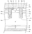
- FIG. 4 It is sectional drawing of the semiconductor device in 1st Embodiment. 4 is a timing chart showing the relationship among a gate-emitter voltage Vge, a collector-emitter current Ice, and a collector-emitter voltage Vce when the semiconductor device transitions from an off state to an on state.
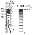
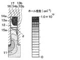
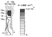
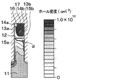
- 3 is a simulation result showing a hole density at a time point T1 in FIG. 2 in the semiconductor device shown in FIG. 3 is a simulation result showing a hole density at a time point T2 in FIG. 2 in the semiconductor device shown in FIG. 3 is a simulation result showing the hole density at time T3 in FIG. 2 in the semiconductor device shown in FIG. 3 is a simulation result showing a hole density at a time T4 in FIG. 2 in the semiconductor device shown in FIG.
- FIG. 3 is a simulation result showing a hole density at a time T5 in FIG. 2 in the semiconductor device shown in FIG. 3 is a simulation result showing a hole density at a time point T6 in FIG. 2 in the semiconductor device shown in FIG. 3 is a simulation result showing a hole density at time T7 in FIG. 2 in the semiconductor device shown in FIG.
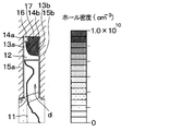
- It is a simulation result which shows the hole density in time T3 in FIG. 2 in the conventional semiconductor device.
- a first embodiment will be described. Note that the semiconductor device of this embodiment is preferably used as a power switching element used in a power supply circuit such as an inverter or a DC / DC converter.
- the semiconductor device has an N ⁇ type semiconductor substrate 10 that functions as a drift layer 11.
- a P-type base layer 12 is formed on the drift layer 11 (that is, on the one surface 10a side of the semiconductor substrate 10).
- a plurality of trenches 13a and 13b that penetrate the base layer 12 and reach the drift layer 11 are formed in the semiconductor substrate 10, and the base layer 12 is divided by the plurality of trenches 13a and 13b.
- the plurality of trenches 13a and 13b are formed at equal intervals in a stripe shape along one direction (that is, the depth direction in FIG. 1) of the surface 10a of the semiconductor substrate 10. .
- the trench 13a will be described as the first trench 13a
- the trench 13b will be described as the second trench 13b.
- the first trench 13a is embedded by a first gate insulating film 14a formed so as to cover the wall surface of the first trench 13a and a first gate electrode 15a formed on the first gate insulating film 14a.
- the second trench 13b includes a second gate insulating film 14b formed so as to cover the wall surface of the second trench 13b, and a second gate electrode 15b formed on the second gate insulating film 14b. Embedded.
- the first gate insulating film 14a and the second gate insulating film 14b are each composed of a silicon oxide film (SiO 2 ) or the like, and the first gate electrode 15a and the second gate electrode 15b are each made of poly It is composed of silicon or the like.
- the first trench 13 a and the second trench 13 b are directions perpendicular to the extending direction of the first trench 13 a and the second trench 13 b and along the surface direction of the semiconductor substrate 10 ( That is, they are alternately formed in the left and right direction on the paper surface in FIG.
- first trench 13a and the second trench 13b are, for example, a plurality of the first trenches 13a and the second trenches 13b in a direction perpendicular to the extending direction of the first trenches 13a and the second trenches 13b and along the surface direction of the semiconductor substrate 10.
- the arrangement order may be changed as appropriate.
- the first gate insulating film 14a has a substantially uniform thickness for each portion on the wall surface of the first trench 13a. Specifically, as will be described later, the first gate electrode 15a is connected to an external gate circuit, and an inversion layer (that is, a channel region) is formed in a portion of the base layer 12 in contact with the first trench 13a. A predetermined gate voltage is applied from the gate circuit. That is, the thickness of the portion of the first gate insulating film 14a that is in contact with the base layer 12 is defined to be a thickness at which the inversion layer can be formed. In other words, the thickness of the portion of the first gate insulating film 14a that is in contact with the base layer 12 is defined by the thickness of the portion that determines the threshold voltage Vth of the MOS gate. The thickness of the other part of the first gate insulating film 14a is also equal to the thickness of the part in contact with the base layer 12 in the first gate insulating film 14a.
- the second gate insulating film 14b has a substantially uniform thickness for each portion on the wall surface of the second trench 13b. However, the second gate insulating film 14b is generally thicker than the first gate insulating film 14a. In the present embodiment, the second gate insulating film 14b is twice as thick as the first gate insulating film 14a.
- the capacitance per unit area of the portion formed on the side surface of the second trench 13b and in contact with the drift layer 11 is defined as the second capacitance.
- a capacitance per unit area of a portion of the first gate insulating film 14a formed on the side surface of the first trench 13a and in contact with the base layer 12 is defined as a first capacitance.
- the second capacity of all the parts is set to be equal to or less than the first capacity.
- the second capacitance of all portions is smaller than the first capacitance.
- N + -type emitter region 16 and a P + -type body region 17 are formed in the surface layer portion of the base layer 12.
- the emitter region 16 is configured to have a higher impurity concentration than the drift layer 11, is terminated in the base layer 12, and is in contact with the side surface of the first trench 13 a.
- the body region 17 has a higher impurity concentration than the base layer 12 and is formed so as to terminate in the base layer 12, similarly to the emitter region 16.
- the emitter region 16 extends in a rod shape so as to be in contact with the side surface of the first trench 13a along the extending direction of the first trench 13a, and terminates inside the tip of the first trench 13a. It is said that.
- the body region 17 extends in a rod shape so as to be in contact with the side surface of the second trench 13b along the extending direction of the second trench 13b, and terminates on the inner side of the tip of the second trench 13b. .
- the body region 17 is formed deeper than the emitter region 16 with respect to the one surface 10 a of the semiconductor substrate 10.
- An interlayer insulating film 18 made of BPSG (abbreviation of Boro-phosphosilicate glass) or the like is formed on one surface 10 a of the semiconductor substrate 10.
- a first contact hole 18 a that exposes a part of the emitter region 16 and the body region 17 is formed, and a second contact hole 18 b that exposes the second gate electrode 15 b is formed.
- the interlayer insulating film 18 is electrically connected to the emitter region 16 and the body region 17 through the first contact hole 18a, and is also connected to the second gate electrode 15b through the second contact hole 18b.
- An upper electrode 19 is formed. That is, in the present embodiment, the second gate electrode 15b has the same potential as the upper electrode 19, and functions as a so-called dummy gate electrode.
- the first gate electrode 15a corresponds to a part of the gate electrode
- the second gate electrode 15b corresponds to the remaining gate electrode
- the upper electrode 19 corresponds to the first electrode.
- the first gate electrode 15a is electrically connected to an external gate circuit via a gate wiring and a gate pad (not shown), and a predetermined gate voltage is applied from the gate circuit.
- An N-type field stop layer (hereinafter simply referred to as an FS layer) 20 is formed on the side of the drift layer 11 opposite to the base layer 12 side (that is, the other surface 10b side of the semiconductor substrate 10).
- this FS layer 20 is not necessarily required, it is possible to improve the breakdown voltage and steady loss performance by preventing the depletion layer from spreading, and to increase the injection amount of holes injected from the other surface 10b side of the semiconductor substrate 10. Be prepared to control.
- a P-type collector layer 21 is formed on the opposite side of the drift layer 11 with the FS layer 20 in between.
- the collector layer 21 and the collector layer 21 are electrically connected to the collector layer 21 (that is, on the other surface 10b of the semiconductor substrate 10).
- a lower electrode 22 to be connected is formed. In the present embodiment, the lower electrode corresponds to the second electrode.
- N + type and N ⁇ type correspond to the first conductivity type
- P type and P + type correspond to the second conductivity type
- the thickness of the second gate insulating film 14b is made equal to the thickness of the first gate insulating film 14a with reference to FIGS. 2 to 5, and the second gate electrode 15b is electrically connected to the upper electrode 19.
- 3A to 3F are simulation results showing the hole density of the semiconductor device of this embodiment at each time point in FIG. 2, and FIGS. 4A to 4F are conventional semiconductor devices at each time point in FIG. It is a simulation result which shows the hole density of. Specifically, FIGS. 3A and 4A show the hole density at time T1, FIGS. 3B and 4B show the hole density at time T2, FIGS.
- FIGS. 3C and 4C show the hole density at time T3
- FIGS. FIG. 4D shows the hole density at time T4.
- 3E and 4E show the hole density at time T5
- FIGS. 3F and 4F show the hole density at time T6
- FIGS. 3G and 4G show the hole density at time T7.
- the semiconductor device transitions from the off state to the on state, the upper electrode 19 is grounded and a positive voltage is applied to the lower electrode 22, and a predetermined gate is applied to the first gate electrode 15a from an external gate circuit. A voltage is applied. As a result, the gate-emitter voltage Vge gradually increases. After that, when the gate potential of the first gate electrode 15a becomes equal to or higher than the threshold voltage Vth of the MOS gate at the time T1, the semiconductor device has an inversion layer (that is, a channel) Region) is formed. In the semiconductor device, electrons are supplied from the emitter region 16 to the drift layer 11 through the inversion layer, and holes are supplied from the collector layer 21 to the drift layer 11.
- the inversion layer that is, a channel
- the resistance value of the drift layer 11 decreases due to conductivity modulation, the collector-emitter current Ice begins to flow, and the collector-emitter voltage (hereinafter simply referred to as the collector voltage) Vce decreases. start.
- the collector voltage Vce becomes substantially constant after reaching the minimum value at time T7.
- it becomes substantially constant after reaching the minimum value at time T6 before time T7. That is, in the semiconductor device of this embodiment, the collector voltage Vce can be reduced to the minimum value earlier than the conventional semiconductor device, and the switching loss when shifting from the off state to the on state can be reduced.
- the drift layer 11 in the second trench 13b Electric charges are accumulated in the contact portion, and a p-type inversion layer is formed. As shown in FIGS. 3A and 4A, the drift layer 11 has a depletion layer d formed between the inversion layer and the drift layer 11.
- the hole density of the drift layer 11 is gradually increased, so that the depletion layer d is reduced.
- the depletion layer d disappears from the vicinity of the side surface of the second trench 13b at time T7.
- the holes supplied to the drift layer 11 are attracted to the inversion layer through the depletion layer d and pass through the inversion layer. Then, it is swept out to the base layer 12 side. Therefore, in the conventional semiconductor device, as shown in FIG. 2, the collector voltage Vce gradually decreases from the vicinity of time T3, and the period until the collector voltage Vce reaches the minimum value becomes longer.
- the second gate insulating film 14b is thicker than the first gate insulating film 14a, and the second capacitance is smaller than the first capacitance.
- connects the 2nd trench 13b of the drift layer 11 decreases. That is, in the semiconductor device of this embodiment, as shown in FIG. 3A, the spread of the depletion layer d is suppressed as compared with FIG. 4A. And in the semiconductor device of this embodiment, the hole supplied to the drift layer 11 becomes difficult to be swept out to the base layer 12 side by suppressing the spread of the depletion layer d.
- the depletion layer d gradually decreases as in the conventional semiconductor device, but is shown in FIG. 3F.
- the depletion layer d disappears from the vicinity of the side surface of the second trench 13b at time T6. Therefore, in the semiconductor device of this embodiment, the collector voltage Vce can be lowered to the minimum value at an early stage as compared with the conventional semiconductor device, and the switching loss when shifting from the off state to the on state can be reduced. Can do.
- the second gate insulating film 14b is thicker than the first gate insulating film 14a, and the second capacitance is smaller than the first capacitance. For this reason, in the semiconductor device of this embodiment, when the semiconductor device is shifted from the off state to the on state, an inversion layer is hardly formed in a portion of the drift layer 11 that is in contact with the second trench 13b. Spreading can be suppressed. Therefore, in the semiconductor device of this embodiment, the holes supplied to the drift layer 11 can be suppressed from being swept out through the inversion layer, and the collector voltage Vce can be lowered to the minimum value at an early stage. Can be reduced.
- the second gate insulating film 14 b is formed such that the thickness of the portion formed on the region in contact with the base layer 12 in the second trench 13 b is the first gate insulating film 14 a. Is equal to the thickness. In the second gate insulating film 14b, the thickness of the portion formed on the region in contact with the drift layer 11 in the second trench 13b is made larger than the thickness of the first gate insulating film 14a.
- the portion on the bottom side of the second trench 13b among the portions formed on the region in contact with the drift layer 11 in the second trench 13b is thickened.
- the portion on the base layer 12 side of the portion formed on the region in contact with the drift layer 11 in the second trench 13b is made equal to the thickness of the first gate insulating film 14a.
- the width of the portion located on the base layer 12 side is made equal to the width of the first gate electrode 15a
- the width of the portion located on the drift layer 11 side is located on the base layer 12 side. It is narrower than the width of the part.
- the width is a direction perpendicular to the extending direction of the first trench 13 a and the second trench 13 b and along the surface direction of the one surface 10 a of the semiconductor substrate 10.
- the second gate insulating film 14b has a second capacitance in the portion on the base layer 12 side in the portion formed on the region in contact with the drift layer 11 in the side surface of the second trench 13b. It is made equal to 1 capacity. Further, in the second gate insulating film 14b, in the portion formed on the region in contact with the drift layer 11 in the side surface of the second trench 13b, the second capacitance at the bottom side of the second trench 13b is the first capacitance. Have been smaller.
- a part of the second capacitance of the second gate insulating film 14b is made smaller than the first capacitance, and the other part of the second capacitance is made equal to the first capacitance. Since the spread of the depletion layer d can be suppressed, the same effect as in the first embodiment can be obtained.
- the first gate insulating film 14a has the same configuration as the second gate insulating film 14b. That is, in the first gate insulating film 14a, the thickness of the portion formed on the region in contact with the drift layer 11 in the first trench 13a is made thicker than the thickness of the portion formed on the region in contact with the base layer 12. ing. In other words, the first gate insulating film 14a is thickened at a portion different from the portion that determines the threshold voltage Vth.
- the same effects as those of the second embodiment can be obtained.
- the first gate insulating film 14a and the second gate insulating film 14b have the same configuration, the first gate insulating film 14a and the second gate insulating film 14b are formed in the same process. Therefore, the manufacturing process can be simplified.
- the second gate insulating film 14b has the same thickness as the first gate insulating film 14a.
- the second gate insulating film 14b is made of a material having a dielectric constant lower than that of the silicon oxide film constituting the first gate insulating film 14a.
- the second capacitance of the second gate insulating film 14b is made smaller than the first capacitance of the first gate insulating film 14a.
- a fluorine-added silicon oxide film (SiOF), a carbon-added silicon oxide film (SiOC), or the like is used as the material having a dielectric constant smaller than that of the silicon oxide film.
- the second gate insulating film 14b is made of a material having a dielectric constant smaller than that of the first gate insulating film 14a, the second capacitance is smaller than the first capacitance. The effect similar to that of the first embodiment can be obtained.
- the first conductivity type is the N type and the second conductivity type is the P type has been described, but the first conductivity type is the P type and the second conductivity type is the N type. It can also be a type.
- the body region 17 may not be in contact with the second trench 13b. That is, the base layer 12 may be present between the body region 17 and the second trench 13b. Further, in the semiconductor device, in addition to the emitter region 16 in contact with the side surface of the first trench 13a, the emitter region 16 in contact with the side surface of the second trench 13b may be formed.
- the second gate electrode 15b and the upper electrode 19 may not be directly electrically connected via the second contact hole 18b.
- the semiconductor device includes a gate pad different from the gate pad to which the first gate electrode 15 a is connected, and the different gate pad is electrically connected to the second gate electrode 15 b and the upper electrode 19. Also good. That is, the second gate electrode 15b may be electrically connected to the upper electrode 19 via a gate pad different from the gate pad to which the first gate electrode 15a is connected.
- the switching loss increases because the holes supplied to the drift layer 11 are formed along the side surfaces of the second trench 13b. This is because it is swept out to the base layer 12 side through the inversion layer.
- the second gate insulating film 14b has the second trench 13b provided that the portion of the side surface of the second trench 13b on the region in contact with the drift layer 11 is thickened. The portion on the bottom surface of the plate may not be thickened.
- a portion of the second gate insulating film 14b formed on the bottom surface of the second trench 13b may be formed of a silicon oxide film.
- the second gate insulating film 14b is formed on a portion of the side surface of the second trench 13b that is in contact with the drift layer 11, and the portion on the base layer 12 side is It may be thickened. That is, the thickness of the portion formed on the region in contact with the drift layer 11 in the side surface of the second trench 13b in the second gate insulating film 14b may be as follows. That is, the thickness of this portion is equal to or greater than the thickness of the portion defining the threshold voltage Vth in the first gate insulating film 14a, and at least part of the thickness is the threshold voltage Vth in the first gate insulating film 14a. What is necessary is just to be thicker than the thickness of the part to prescribe
- the 2nd gate insulating film 14b should just be made as follows in the part formed in the area
- the width of the second gate electrode 15b may be constant in the thickness direction of the semiconductor substrate 10.
- the width of the bottom side portion of the second trench 13b is made longer than the width of the opening side, and the second trench 13b of the second gate insulating film 14b. What is necessary is just to thicken the part of the bottom part side.
- the second gate insulating film 14b is the first gate as long as the second capacitance is equal to or lower than the first capacitance and at least a portion of the second capacitance is smaller than the first capacitance. It may be thinner than the gate insulating film 14a.
- the fourth embodiment may be combined with the first to third embodiments, and the second gate insulating film 14b may be made of a material having a lower dielectric constant than the first gate insulating film 14a.
Landscapes
- Engineering & Computer Science (AREA)
- Microelectronics & Electronic Packaging (AREA)
- Power Engineering (AREA)
- Physics & Mathematics (AREA)
- Ceramic Engineering (AREA)
- Condensed Matter Physics & Semiconductors (AREA)
- General Physics & Mathematics (AREA)
- Computer Hardware Design (AREA)
- Electrodes Of Semiconductors (AREA)
Abstract
L'invention concerne un dispositif à semiconducteur dans lequel, une première électrode de grille (15a) est disposée par l'intermédiaire d'un premier film d'isolation de grille (14a) sur une première tranchée (13a), une seconde électrode de grille (15b) est disposée par l'intermédiaire d'un second film d'isolation de grille (14b) sur une seconde tranchée (13b), une tension de grille est appliquée à la première électrode de grille (15a), et la seconde électrode de grille (15b) est électriquement connectée à une première électrode (19). De plus, une seconde capacité par unité de surface de l'ensemble de la partie, du second film isolant de grille (14b), qui est formée sur une zone en contact avec une couche de dérive (11) sur une surface latérale de la seconde tranchée (13b) est réglée pour ne pas être supérieure à une première capacité par unité de surface d'une partie, du premier film d'isolation de grille (14a), qui est formée sur une zone en contact avec une couche de base (12) sur une surface latérale de la première tranchée (13a), et la seconde capacité d'au moins une partie est réglée pour être inférieure à la première capacité.
Priority Applications (2)
| Application Number | Priority Date | Filing Date | Title |
|---|---|---|---|
| CN201780067304.1A CN109891597A (zh) | 2016-11-15 | 2017-11-09 | 半导体装置 |
| US16/351,755 US10720518B2 (en) | 2016-11-15 | 2019-03-13 | Semiconductor device |
Applications Claiming Priority (2)
| Application Number | Priority Date | Filing Date | Title |
|---|---|---|---|
| JP2016-222540 | 2016-11-15 | ||
| JP2016222540A JP2018082010A (ja) | 2016-11-15 | 2016-11-15 | 半導体装置 |
Related Child Applications (1)
| Application Number | Title | Priority Date | Filing Date |
|---|---|---|---|
| US16/351,755 Continuation US10720518B2 (en) | 2016-11-15 | 2019-03-13 | Semiconductor device |
Publications (1)
| Publication Number | Publication Date |
|---|---|
| WO2018092680A1 true WO2018092680A1 (fr) | 2018-05-24 |
Family
ID=62145233
Family Applications (1)
| Application Number | Title | Priority Date | Filing Date |
|---|---|---|---|
| PCT/JP2017/040490 WO2018092680A1 (fr) | 2016-11-15 | 2017-11-09 | Dispositif à semiconducteur |
Country Status (4)
| Country | Link |
|---|---|
| US (1) | US10720518B2 (fr) |
| JP (1) | JP2018082010A (fr) |
| CN (1) | CN109891597A (fr) |
| WO (1) | WO2018092680A1 (fr) |
Families Citing this family (3)
| Publication number | Priority date | Publication date | Assignee | Title |
|---|---|---|---|---|
| US11257916B2 (en) * | 2019-03-14 | 2022-02-22 | Semiconductor Components Industries, Llc | Electronic device having multi-thickness gate insulator |
| JP7184681B2 (ja) * | 2019-03-18 | 2022-12-06 | 株式会社東芝 | 半導体装置およびその制御方法 |
| JP7337619B2 (ja) | 2019-09-17 | 2023-09-04 | 株式会社東芝 | 半導体装置 |
Citations (1)
| Publication number | Priority date | Publication date | Assignee | Title |
|---|---|---|---|---|
| JP2006245477A (ja) * | 2005-03-07 | 2006-09-14 | Toshiba Corp | 半導体装置 |
Family Cites Families (11)
| Publication number | Priority date | Publication date | Assignee | Title |
|---|---|---|---|---|
| JP2004022941A (ja) | 2002-06-19 | 2004-01-22 | Toshiba Corp | 半導体装置 |
| JP5831598B2 (ja) * | 2010-12-08 | 2015-12-09 | 株式会社デンソー | 絶縁ゲート型半導体装置 |
| JP2012204377A (ja) * | 2011-03-23 | 2012-10-22 | Toshiba Corp | 電力用半導体装置 |
| JP6182849B2 (ja) | 2012-11-13 | 2017-08-23 | サンケン電気株式会社 | 半導体装置の製造方法 |
| US9337270B2 (en) * | 2013-12-19 | 2016-05-10 | Infineon Technologies Ag | Semiconductor device |
| US9337185B2 (en) * | 2013-12-19 | 2016-05-10 | Infineon Technologies Ag | Semiconductor devices |
| CN104103523A (zh) * | 2014-07-25 | 2014-10-15 | 苏州东微半导体有限公司 | 一种带u形沟槽的功率器件的制造方法 |
| JP2016046416A (ja) * | 2014-08-25 | 2016-04-04 | 富士電機株式会社 | 半導体装置 |
| JP6260515B2 (ja) * | 2014-11-13 | 2018-01-17 | 三菱電機株式会社 | 半導体装置 |
| DE102014119466A1 (de) * | 2014-12-22 | 2016-06-23 | Infineon Technologies Ag | Halbleitervorrichtung mit streifenförmigen trenchgatestrukturen und gateverbinderstruktur |
| WO2016136230A1 (fr) * | 2015-02-25 | 2016-09-01 | 株式会社デンソー | Dispositif à semi-conducteur |
-
2016
- 2016-11-15 JP JP2016222540A patent/JP2018082010A/ja active Pending
-
2017
- 2017-11-09 WO PCT/JP2017/040490 patent/WO2018092680A1/fr active Application Filing
- 2017-11-09 CN CN201780067304.1A patent/CN109891597A/zh active Pending
-
2019
- 2019-03-13 US US16/351,755 patent/US10720518B2/en active Active
Patent Citations (1)
| Publication number | Priority date | Publication date | Assignee | Title |
|---|---|---|---|---|
| JP2006245477A (ja) * | 2005-03-07 | 2006-09-14 | Toshiba Corp | 半導体装置 |
Also Published As
| Publication number | Publication date |
|---|---|
| US10720518B2 (en) | 2020-07-21 |
| JP2018082010A (ja) | 2018-05-24 |
| US20190214491A1 (en) | 2019-07-11 |
| CN109891597A (zh) | 2019-06-14 |
Similar Documents
| Publication | Publication Date | Title |
|---|---|---|
| JP6720569B2 (ja) | 半導体装置 | |
| JP5742672B2 (ja) | 半導体装置 | |
| JP6253769B2 (ja) | 電力用半導体装置 | |
| WO2016009616A1 (fr) | Dispositif à semi-conducteurs | |
| JP4205128B2 (ja) | 高耐圧半導体装置およびその製造方法 | |
| JP2005340626A (ja) | 半導体装置 | |
| WO2013179648A1 (fr) | Dispositif à semi-conducteur | |
| WO2017033315A1 (fr) | Élément semi-conducteur | |
| CN103855217B (zh) | 包括沟槽的半导体器件和制造半导体器件的方法 | |
| JP2006245477A (ja) | 半導体装置 | |
| WO2018092680A1 (fr) | Dispositif à semiconducteur | |
| JP5200373B2 (ja) | 半導体装置 | |
| JP2011055017A (ja) | 半導体装置 | |
| KR20160029630A (ko) | 반도체 장치 | |
| JP2014154739A (ja) | 半導体装置 | |
| JP7330092B2 (ja) | 半導体装置 | |
| US10748988B2 (en) | Semiconductor device | |
| JP2016062975A (ja) | 半導体装置およびその製造方法 | |
| JP2005327806A (ja) | 絶縁ゲート型バイポーラトランジスタ | |
| JP6729478B2 (ja) | 半導体装置 | |
| JP2007266622A (ja) | 高耐圧半導体装置およびその製造方法 | |
| US9391183B2 (en) | Semiconductor device | |
| WO2016136230A1 (fr) | Dispositif à semi-conducteur | |
| JP3193413U (ja) | 半導体装置 | |
| JP2019197850A (ja) | 半導体装置およびその製造方法 |
Legal Events
| Date | Code | Title | Description |
|---|---|---|---|
| 121 | Ep: the epo has been informed by wipo that ep was designated in this application |
Ref document number: 17871388 Country of ref document: EP Kind code of ref document: A1 |
|
| NENP | Non-entry into the national phase |
Ref country code: DE |
|
| 122 | Ep: pct application non-entry in european phase |
Ref document number: 17871388 Country of ref document: EP Kind code of ref document: A1 |