WO2018062236A1 - 泡吐出容器 - Google Patents
泡吐出容器 Download PDFInfo
- Publication number
- WO2018062236A1 WO2018062236A1 PCT/JP2017/034883 JP2017034883W WO2018062236A1 WO 2018062236 A1 WO2018062236 A1 WO 2018062236A1 JP 2017034883 W JP2017034883 W JP 2017034883W WO 2018062236 A1 WO2018062236 A1 WO 2018062236A1
- Authority
- WO
- WIPO (PCT)
- Prior art keywords
- discharge
- foam
- discharge port
- container
- pressing
- Prior art date
Links
Images


Classifications
-
- B—PERFORMING OPERATIONS; TRANSPORTING
- B65—CONVEYING; PACKING; STORING; HANDLING THIN OR FILAMENTARY MATERIAL
- B65D—CONTAINERS FOR STORAGE OR TRANSPORT OF ARTICLES OR MATERIALS, e.g. BAGS, BARRELS, BOTTLES, BOXES, CANS, CARTONS, CRATES, DRUMS, JARS, TANKS, HOPPERS, FORWARDING CONTAINERS; ACCESSORIES, CLOSURES, OR FITTINGS THEREFOR; PACKAGING ELEMENTS; PACKAGES
- B65D83/00—Containers or packages with special means for dispensing contents
- B65D83/14—Containers or packages with special means for dispensing contents for delivery of liquid or semi-liquid contents by internal gaseous pressure, i.e. aerosol containers comprising propellant for a product delivered by a propellant
- B65D83/16—Containers or packages with special means for dispensing contents for delivery of liquid or semi-liquid contents by internal gaseous pressure, i.e. aerosol containers comprising propellant for a product delivered by a propellant characterised by the actuating means
- B65D83/20—Containers or packages with special means for dispensing contents for delivery of liquid or semi-liquid contents by internal gaseous pressure, i.e. aerosol containers comprising propellant for a product delivered by a propellant characterised by the actuating means operated by manual action, e.g. button-type actuator or actuator caps
-
- B—PERFORMING OPERATIONS; TRANSPORTING
- B05—SPRAYING OR ATOMISING IN GENERAL; APPLYING FLUENT MATERIALS TO SURFACES, IN GENERAL
- B05B—SPRAYING APPARATUS; ATOMISING APPARATUS; NOZZLES
- B05B11/00—Single-unit hand-held apparatus in which flow of contents is produced by the muscular force of the operator at the moment of use
- B05B11/0005—Components or details
- B05B11/0037—Containers
-
- A—HUMAN NECESSITIES
- A47—FURNITURE; DOMESTIC ARTICLES OR APPLIANCES; COFFEE MILLS; SPICE MILLS; SUCTION CLEANERS IN GENERAL
- A47K—SANITARY EQUIPMENT NOT OTHERWISE PROVIDED FOR; TOILET ACCESSORIES
- A47K5/00—Holders or dispensers for soap, toothpaste, or the like
- A47K5/14—Foam or lather making devices
- A47K5/16—Foam or lather making devices with mechanical drive
-
- A—HUMAN NECESSITIES
- A47—FURNITURE; DOMESTIC ARTICLES OR APPLIANCES; COFFEE MILLS; SPICE MILLS; SUCTION CLEANERS IN GENERAL
- A47K—SANITARY EQUIPMENT NOT OTHERWISE PROVIDED FOR; TOILET ACCESSORIES
- A47K5/00—Holders or dispensers for soap, toothpaste, or the like
- A47K5/14—Foam or lather making devices
-
- B—PERFORMING OPERATIONS; TRANSPORTING
- B05—SPRAYING OR ATOMISING IN GENERAL; APPLYING FLUENT MATERIALS TO SURFACES, IN GENERAL
- B05B—SPRAYING APPARATUS; ATOMISING APPARATUS; NOZZLES
- B05B1/00—Nozzles, spray heads or other outlets, with or without auxiliary devices such as valves, heating means
- B05B1/02—Nozzles, spray heads or other outlets, with or without auxiliary devices such as valves, heating means designed to produce a jet, spray, or other discharge of particular shape or nature, e.g. in single drops, or having an outlet of particular shape
-
- B—PERFORMING OPERATIONS; TRANSPORTING
- B05—SPRAYING OR ATOMISING IN GENERAL; APPLYING FLUENT MATERIALS TO SURFACES, IN GENERAL
- B05B—SPRAYING APPARATUS; ATOMISING APPARATUS; NOZZLES
- B05B11/00—Single-unit hand-held apparatus in which flow of contents is produced by the muscular force of the operator at the moment of use
- B05B11/01—Single-unit hand-held apparatus in which flow of contents is produced by the muscular force of the operator at the moment of use characterised by the means producing the flow
- B05B11/10—Pump arrangements for transferring the contents from the container to a pump chamber by a sucking effect and forcing the contents out through the dispensing nozzle
- B05B11/1001—Piston pumps
- B05B11/1009—Piston pumps actuated by a lever
- B05B11/1012—Piston pumps actuated by a lever the pump chamber being arranged substantially coaxially to the neck of the container
-
- B—PERFORMING OPERATIONS; TRANSPORTING
- B05—SPRAYING OR ATOMISING IN GENERAL; APPLYING FLUENT MATERIALS TO SURFACES, IN GENERAL
- B05B—SPRAYING APPARATUS; ATOMISING APPARATUS; NOZZLES
- B05B11/00—Single-unit hand-held apparatus in which flow of contents is produced by the muscular force of the operator at the moment of use
- B05B11/01—Single-unit hand-held apparatus in which flow of contents is produced by the muscular force of the operator at the moment of use characterised by the means producing the flow
- B05B11/10—Pump arrangements for transferring the contents from the container to a pump chamber by a sucking effect and forcing the contents out through the dispensing nozzle
- B05B11/1042—Components or details
-
- B—PERFORMING OPERATIONS; TRANSPORTING
- B05—SPRAYING OR ATOMISING IN GENERAL; APPLYING FLUENT MATERIALS TO SURFACES, IN GENERAL
- B05B—SPRAYING APPARATUS; ATOMISING APPARATUS; NOZZLES
- B05B9/00—Spraying apparatus for discharge of liquids or other fluent material, without essentially mixing with gas or vapour
- B05B9/03—Spraying apparatus for discharge of liquids or other fluent material, without essentially mixing with gas or vapour characterised by means for supplying liquid or other fluent material
- B05B9/04—Spraying apparatus for discharge of liquids or other fluent material, without essentially mixing with gas or vapour characterised by means for supplying liquid or other fluent material with pressurised or compressible container; with pump
-
- B—PERFORMING OPERATIONS; TRANSPORTING
- B65—CONVEYING; PACKING; STORING; HANDLING THIN OR FILAMENTARY MATERIAL
- B65D—CONTAINERS FOR STORAGE OR TRANSPORT OF ARTICLES OR MATERIALS, e.g. BAGS, BARRELS, BOTTLES, BOXES, CANS, CARTONS, CRATES, DRUMS, JARS, TANKS, HOPPERS, FORWARDING CONTAINERS; ACCESSORIES, CLOSURES, OR FITTINGS THEREFOR; PACKAGING ELEMENTS; PACKAGES
- B65D47/00—Closures with filling and discharging, or with discharging, devices
-
- B—PERFORMING OPERATIONS; TRANSPORTING
- B65—CONVEYING; PACKING; STORING; HANDLING THIN OR FILAMENTARY MATERIAL
- B65D—CONTAINERS FOR STORAGE OR TRANSPORT OF ARTICLES OR MATERIALS, e.g. BAGS, BARRELS, BOTTLES, BOXES, CANS, CARTONS, CRATES, DRUMS, JARS, TANKS, HOPPERS, FORWARDING CONTAINERS; ACCESSORIES, CLOSURES, OR FITTINGS THEREFOR; PACKAGING ELEMENTS; PACKAGES
- B65D83/00—Containers or packages with special means for dispensing contents
- B65D83/14—Containers or packages with special means for dispensing contents for delivery of liquid or semi-liquid contents by internal gaseous pressure, i.e. aerosol containers comprising propellant for a product delivered by a propellant
- B65D83/16—Containers or packages with special means for dispensing contents for delivery of liquid or semi-liquid contents by internal gaseous pressure, i.e. aerosol containers comprising propellant for a product delivered by a propellant characterised by the actuating means
-
- B—PERFORMING OPERATIONS; TRANSPORTING
- B65—CONVEYING; PACKING; STORING; HANDLING THIN OR FILAMENTARY MATERIAL
- B65D—CONTAINERS FOR STORAGE OR TRANSPORT OF ARTICLES OR MATERIALS, e.g. BAGS, BARRELS, BOTTLES, BOXES, CANS, CARTONS, CRATES, DRUMS, JARS, TANKS, HOPPERS, FORWARDING CONTAINERS; ACCESSORIES, CLOSURES, OR FITTINGS THEREFOR; PACKAGING ELEMENTS; PACKAGES
- B65D83/00—Containers or packages with special means for dispensing contents
- B65D83/14—Containers or packages with special means for dispensing contents for delivery of liquid or semi-liquid contents by internal gaseous pressure, i.e. aerosol containers comprising propellant for a product delivered by a propellant
- B65D83/28—Nozzles, nozzle fittings or accessories specially adapted therefor
-
- A—HUMAN NECESSITIES
- A45—HAND OR TRAVELLING ARTICLES
- A45D—HAIRDRESSING OR SHAVING EQUIPMENT; EQUIPMENT FOR COSMETICS OR COSMETIC TREATMENTS, e.g. FOR MANICURING OR PEDICURING
- A45D27/00—Shaving accessories
- A45D27/02—Lathering the body; Producing lather
-
- B—PERFORMING OPERATIONS; TRANSPORTING
- B05—SPRAYING OR ATOMISING IN GENERAL; APPLYING FLUENT MATERIALS TO SURFACES, IN GENERAL
- B05B—SPRAYING APPARATUS; ATOMISING APPARATUS; NOZZLES
- B05B11/00—Single-unit hand-held apparatus in which flow of contents is produced by the muscular force of the operator at the moment of use
- B05B11/0005—Components or details
- B05B11/0059—Components or details allowing operation in any orientation, e.g. for discharge in inverted position
-
- B—PERFORMING OPERATIONS; TRANSPORTING
- B05—SPRAYING OR ATOMISING IN GENERAL; APPLYING FLUENT MATERIALS TO SURFACES, IN GENERAL
- B05B—SPRAYING APPARATUS; ATOMISING APPARATUS; NOZZLES
- B05B11/00—Single-unit hand-held apparatus in which flow of contents is produced by the muscular force of the operator at the moment of use
- B05B11/0005—Components or details
- B05B11/0089—Dispensing tubes
-
- B—PERFORMING OPERATIONS; TRANSPORTING
- B05—SPRAYING OR ATOMISING IN GENERAL; APPLYING FLUENT MATERIALS TO SURFACES, IN GENERAL
- B05B—SPRAYING APPARATUS; ATOMISING APPARATUS; NOZZLES
- B05B11/00—Single-unit hand-held apparatus in which flow of contents is produced by the muscular force of the operator at the moment of use
- B05B11/01—Single-unit hand-held apparatus in which flow of contents is produced by the muscular force of the operator at the moment of use characterised by the means producing the flow
- B05B11/10—Pump arrangements for transferring the contents from the container to a pump chamber by a sucking effect and forcing the contents out through the dispensing nozzle
- B05B11/1001—Piston pumps
- B05B11/1009—Piston pumps actuated by a lever
- B05B11/1012—Piston pumps actuated by a lever the pump chamber being arranged substantially coaxially to the neck of the container
- B05B11/1014—Piston pumps actuated by a lever the pump chamber being arranged substantially coaxially to the neck of the container the pump chamber being arranged substantially coaxially to the container
-
- B—PERFORMING OPERATIONS; TRANSPORTING
- B05—SPRAYING OR ATOMISING IN GENERAL; APPLYING FLUENT MATERIALS TO SURFACES, IN GENERAL
- B05B—SPRAYING APPARATUS; ATOMISING APPARATUS; NOZZLES
- B05B11/00—Single-unit hand-held apparatus in which flow of contents is produced by the muscular force of the operator at the moment of use
- B05B11/01—Single-unit hand-held apparatus in which flow of contents is produced by the muscular force of the operator at the moment of use characterised by the means producing the flow
- B05B11/10—Pump arrangements for transferring the contents from the container to a pump chamber by a sucking effect and forcing the contents out through the dispensing nozzle
- B05B11/1087—Combination of liquid and air pumps
-
- B—PERFORMING OPERATIONS; TRANSPORTING
- B05—SPRAYING OR ATOMISING IN GENERAL; APPLYING FLUENT MATERIALS TO SURFACES, IN GENERAL
- B05B—SPRAYING APPARATUS; ATOMISING APPARATUS; NOZZLES
- B05B7/00—Spraying apparatus for discharge of liquids or other fluent materials from two or more sources, e.g. of liquid and air, of powder and gas
- B05B7/0018—Spraying apparatus for discharge of liquids or other fluent materials from two or more sources, e.g. of liquid and air, of powder and gas with devices for making foam
- B05B7/0025—Spraying apparatus for discharge of liquids or other fluent materials from two or more sources, e.g. of liquid and air, of powder and gas with devices for making foam with a compressed gas supply
- B05B7/0031—Spraying apparatus for discharge of liquids or other fluent materials from two or more sources, e.g. of liquid and air, of powder and gas with devices for making foam with a compressed gas supply with disturbing means promoting mixing, e.g. balls, crowns
- B05B7/0037—Spraying apparatus for discharge of liquids or other fluent materials from two or more sources, e.g. of liquid and air, of powder and gas with devices for making foam with a compressed gas supply with disturbing means promoting mixing, e.g. balls, crowns including sieves, porous members or the like
Definitions
- the present invention relates to a foam discharge container.
- Patent Literature 1 describes a foam discharge container that discharges a liquid agent contained in a container body as a foam by pressing a head portion.
- a plurality of circular discharge ports are discretely arranged at positions corresponding to the apexes and centers of triangles and pentagons.
- the positions and diameters of the discharge ports are set so that the foam discharged from the plurality of discharge ports sticks to each other, so that a foam-shaped article imitating a character is formed.
- the present invention is a foam discharge container for discharging foam in response to a pressing operation, An opening that opens in a direction opposite to the pressing direction by the pressing operation, and discharges the bubbles; and A pressing unit that maintains a constant distance between the discharge target that receives the bubbles and the discharge port;
- the present invention relates to a foam discharge container.
- the present invention is a liquid agent discharge container for discharging a liquid agent according to a pressing operation
- the liquid agent discharge cap is An opening that opens in the opposite direction to the pressing direction by the pressing operation, and discharges the liquid agent;
- a pressing portion that maintains a constant distance between the discharge target that receives the liquid and the discharge port;
- a pump unit that discharges the liquid agent from the discharge port by moving the container body in the pressing direction relative to the pressing unit;
- the said container main body is related with the liquid agent discharge container which is an operation part hold
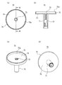
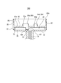
- FIG. 5A, FIG. 5B, FIG. 5C, and FIG. 5D are views showing the first head member of the foam discharge container according to the first embodiment.
- FIG. 6A, FIG. 6B, FIG. 6C, and FIG. 6D are views showing the second head member of the foam discharge container according to the first embodiment.
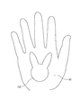
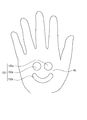
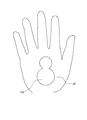
- FIG. 15 is a cross-sectional view taken along line AA in FIG. 14. It is a top view which shows the state in which the foam molded article was received by the to-be-discharged body (hand) in 4th Embodiment.
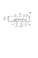
- FIG. 17A and FIG. 17B are views showing a head member of a foam discharge container according to the fifth embodiment. It is a figure which shows the head member of the foam discharge container which concerns on 6th Embodiment. It is front sectional drawing which shows the upper part of the foam discharge container which concerns on 7th Embodiment.
- 20 (a), 20 (b), 20 (c) and 20 (d) are views showing a foam discharge head of the foam discharge container according to the seventh embodiment. It is a top view which shows the state in which foam was received by the to-be-discharged body (plate) in 7th Embodiment. It is front sectional drawing of the foam discharge container which concerns on 8th Embodiment. It is front sectional drawing of the foam discharge container which concerns on 9th Embodiment. It is a top view which shows the foam discharge head of the foam discharge container which concerns on 9th Embodiment. 25 (a), 25 (b) and 25 (c) are views showing a foam discharge head of a foam discharge container according to the ninth embodiment.
- the present invention relates to a foam discharge container, a foam discharge cap, and a foam discharge head capable of receiving foam on an object to be discharged such as a hand by one-hand operation.
- the present invention also relates to a liquid agent discharge container capable of receiving a liquid agent on an object to be discharged such as a hand by one-hand operation.
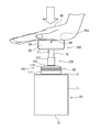
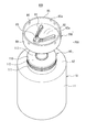
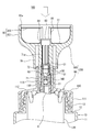
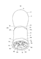
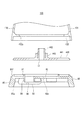
- FIGS. 1-8 the foam discharge container 100, the foam discharge cap 200, and the foam discharge head 300 which concern on 1st Embodiment are demonstrated using FIGS. 1-8.
- the downward direction is downward and the upward direction is upward. That is, the downward direction (downward) is a direction of gravity in a state where the bottom portion 14 of the foam discharge container 100 is placed and the foam discharge container 100 is self-supporting.
- the downward direction is a direction of gravity in a state where the bottom portion 14 of the foam discharge container 100 is placed and the foam discharge container 100 is self-supporting.
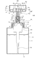
- FIG. 3 only the outline is shown for the portion below the break line H in the foam discharge cap 200.
- the foam discharge container 100 is a foam discharge container 100 that discharges bubbles in response to a pressing operation, and is opposite to the pressing direction (downward in the present embodiment) by the pressing operation.
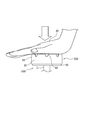
- a discharge port 83 that opens in a direction (upward in the present embodiment) and discharges bubbles, a discharge target 40 that receives bubbles (for example, a hand as shown in FIGS. 1 and 8), and a discharge port 83.
- a pressing portion 85 that maintains the distance constant. Therefore, the direction opposite to the pressing direction is also the discharge direction from the discharge port 83.
- the pressing direction by the pressing operation is the operation direction.
- the foam ejection container 100 includes a foam ejection head 300 that ejects foam in response to a pressing operation, and the foam ejection head 300 includes a pressing unit 85.
- the pressing portion 85 has an upright portion that stands up at a position spaced outward from the discharge port 83.
- the pressing portion 85 has a standing portion, thereby forming a distance between the discharge port 83 and the discharge target body 40.
- the pressing direction is a direction in which the foam discharge head 300 is pressed relative to the container body 10 by a pressing operation.
- the outward direction is a direction from the ejection port 83 toward a position outside the ejection port 83 when the bubble ejection head 300 is viewed from above.
- the pressing operation since the direction in which the foam ejection head 300 is pressed by the pressing operation is downward, the pressing operation may be referred to as a pressing operation of the foam ejection head 300.
- the pressing direction and the direction opposite to the pressing direction are not necessarily different from each other by 180 degrees on the same straight line, and may be approximately opposite directions. Therefore, a certain amount of axial deviation (for example, axial deviation within 10 degrees) is allowed between the pressing direction and the direction opposite to the pressing direction.
- maintaining the distance between the discharge target 40 and the discharge port 83 constant means that the distance between the discharge target 40 and the discharge port 83 at the end of the pressing operation is constant in each pressing operation.
- the distance between the discharge target 40 and the discharge port 83 is allowed to change between the start stage and the end stage of the pressing operation.
- the pressing portion 85 may be constantly crushed or bent by a pressing operation each time.
- the amount of change in the distance is constant in each pressing operation.
- the entire foam discharge head 300 is substantially rigid, and the distance between the discharge target 40 and the discharge port 83 is kept constant from the start stage to the end stage of the pressing operation. It has become.
- maintaining the distance between the discharge target 40 and the discharge port 83 constant means that the discharge target 40 and the discharge port 83 are separated from each other as can be seen from FIGS. And maintaining the discharge port 83 in a non-contact state). From the start stage to the end stage of the pressing operation, the discharged body 40 and the discharge port 83 are maintained in a separated state. According to the present embodiment, it is possible to receive foam on a discharged body such as a hand by one-hand operation.
- the foam discharge container 100 includes a container main body 10 that stores the liquid agent 101 (FIG. 3), and a foam discharge cap 200 that is detachably attached to the container main body 10.
- the foam discharge cap 200 is configured by a portion of the configuration of the foam discharge container 100 excluding the container body 10.
- the foam discharge cap 200 is used by being attached to the container body 10 that stores the liquid agent 101, and is a foam discharge cap 200 that discharges bubbles in response to a pressing operation, and includes the above-described discharge port 83 and the pressing portion 85. ing.
- the foam discharge cap 200 includes a cap 90 that is detachably attached to the container body 10 and a foam discharge head 300 that is used by being attached to the cap 90 (for example, detachable). Yes.
- the foam ejection head 300 is configured by a portion excluding the cap 90 in the configuration of the foam ejection cap 200.
- the foam discharge head 300 is used by being attached to a cap 90 attached to the container body 10 that stores the liquid agent 101, and discharges bubbles in response to a pressing operation. It has. That is, when the foam discharge head 300 is attached to the cap 90 and the cap 90 is attached to the container body 10, a pressure operation is performed on the foam discharge head 300, whereby the foam discharge head 300 generates bubbles. Discharge.
- the foam discharge head 300 is attached to the upper end portion of the piston guide 140 included in the pump portion 120 of the cap 90.
- a hand soap can be cited as a representative example of the liquid 101, but is not limited thereto.
- Cosmetics for skin such as liquids, hair dyes, disinfectants, creams applied to foods such as bread, detergents for households, disinfectants, detergents for clothes for partial washing, etc. Can be illustrated.
- the viscosity of the liquid 101 before foaming that is, the viscosity of the liquid 101 in the container body 10 is not particularly limited, and can be, for example, about 1 mPa ⁇ s or more and 20 mPa ⁇ s or less at 20 ° C.
- the viscosity of the liquid 101 is measured with a B-type viscometer.
- a B-type viscometer one having a rotor selected according to the viscosity is used. This rotor rotates at a rotational speed of 60 revolutions / minute. Measure the viscosity 60 seconds after the start of rotation of the rotor.
- Examples of the discharged object 40 that receives bubbles of a desired shape include foods such as bread to which a sponge or cream for washing or application is applied, in addition to hands.
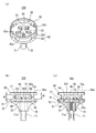
- the container main body 10 protrudes upward from, for example, the trunk 11, the shoulder 12 connected to the upper end of the trunk 11, and the center of the shoulder 12. It has a cylindrical mouth-and-neck part 13 (FIG. 3) and a bottom part 14 that closes the lower end of the body part 11. The upper end of the mouth-and-neck portion 13 is open.
- the foam discharge container 100 can be self-supporting in a state where the bottom portion 14 is placed on a horizontal placement surface. Further, the foam can be discharged from the discharge port 83 by performing a pressing operation on the foam discharge head 300 in a state where the foam discharge container 100 is self-supporting.
- the foam discharge container 100 is, for example, a manual pump container (pump former), and the container body 10 stores the liquid 101 at normal pressure. Further, the foam discharge cap 200 includes a former mechanism 20 that foams the liquid agent 101.
- the cap 90 is operated in conjunction with a cap member 110 that is detachably attached to the mouth-and-neck portion 13 and a depressing operation of the foam discharge head 300, whereby the liquid agent 101 and the air are formed.
- the pump part 120 which sends out to the mechanism 20 and discharges foam from the discharge port 83, and the dip tube 130 for sucking up the liquid agent 101 in the container main body 10 to the pump part 120 are provided. At the tip of the dip tube 130, an inlet for sucking the liquid 101 in the container body 10 is formed.
- the structure of the pump unit 120 is well known and will not be described in detail in this specification.
- the cap 90 foams the liquid agent 101 when the foam discharge head 300 is pressed, and discharges the foam.
- the foam-like liquid agent 101 is referred to as a foam and is distinguished from the non-foam-like liquid agent 101 stored in the container body 10.
- the cap member 110 includes a cylindrical mounting portion 111 that is detachably mounted to the mouth and neck portion 13 by a fastening method such as screwing, and an annular closing portion 112 that closes the upper end portion of the mounting portion 111. And an upright tube portion 113 which is formed in a cylindrical shape having a smaller diameter than the mounting portion 111 and rises upward from the center portion of the annular closing portion 112.
- the mounting portion 111 is formed in a double cylinder structure, and an inner cylindrical portion of the mounting portion 111 may be screwed to the mouth neck portion 13 or may be configured as a single cylindrical shape. May be.
- the former mechanism 20 includes a gas-liquid mixing unit 21 in which the liquid 101 delivered by the pump unit 120 and air are mixed. By mixing the liquid agent 101 and air in the gas-liquid mixing unit 21, the liquid agent 101 is foamed (bubbles are generated).
- the pump unit 120 includes a liquid agent valve including a ball valve 190, and this liquid agent valve is disposed facing the gas-liquid mixing unit 21. When a pressing operation is performed on the foam discharge head 300, the ball valve 190 is pushed up to open the liquid agent valve, and the liquid agent 101 flows into the gas-liquid mixing unit 21 (that is, the liquid agent 101 is sent to the gas-liquid mixing unit 21). It is like that.
- the pump unit 120 is configured to simultaneously send air to the gas-liquid mixing unit 21.
- a cylindrical ring member 60 is disposed above the ball valve 190.
- the ring member 60 is, for example, a jet ring included in a well-known foam discharge container, and is disposed inside a cylinder portion 71 described later in a posture in which the axial center direction of the ring member 60 extends vertically.
- a cylindrical mesh retaining ring 50 is provided, for example, in two upper and lower stages.
- a mesh 51 is provided in each of the opening at the lower end of the lower mesh holding ring 50 and the opening at the upper end of the upper mesh holding ring 50.
- the internal space of the ring member 60 constitutes a part of the gas-liquid mixing unit 21, for example.
- the mesh holding ring 50 and the mesh 51 constitute the former mechanism 20 together with the gas-liquid mixing unit 21. When the bubbles generated in the gas-liquid mixing unit 21 pass through the mesh 51, the bubbles become finer and more uniform.
- the foam discharge head 300 is composed of, for example, two members, a first head member 70 and a second head member 80 described below.
- FIGS. 5A, 5B, 5C, and 5D are plan views of the first head member 70
- FIG. 5 (b) is a sectional view taken along line BB of FIG. 5 (a) (side sectional view of the first head member 70)
- FIG. (C) is the perspective view which looked at the 1st head member 70 from diagonally upward
- FIG.5 (d) is the perspective view which looked at the 1st head member 70 from diagonally downward.
- the first head member 70 is, for example, a cylindrical (circular tubular) cylindrical portion 71. And a primary plate-like portion 74 connected to the upper end of the cylindrical portion 71, and an annular wall 75 connected to the upper side of the primary plate-like portion 74.
- the internal space of the cylindrical portion 71 communicates with the internal space of the nozzle forming wall 84, and the cylindrical portion 71 supplies bubbles to the internal space of the nozzle forming wall 84.
- the ring member 60 is held in a holding portion 72 that is a partial region of the internal space of the cylindrical portion 71 (see FIGS. 3 and 4). That is, the ring member 60 holding the two-stage mesh holding ring 50 is fixed to the holding portion 72 by being inserted into the cylindrical portion 71 from the lower end of the cylindrical portion 71.
- a plurality of vertical ribs for positioning the ring member 60 by restricting the ring member 60 from moving upward are formed on the inner peripheral surface of the cylindrical portion 71 above the holding portion 72 (see FIG. 4, see FIG. 5 (b)).
- the primary plate-like portion 74 is formed in a flat plate shape, for example, and the plate surface of the primary plate-like portion 74 is orthogonal to the axial center of the cylindrical portion 71.
- the planar shape of the primary plate-like portion 74 is not particularly limited, for example, it is circular as shown in FIG.
- a primary discharge port 73 is formed at the center of the primary plate-like portion 74.
- the planar shape of the primary discharge port 73 is, for example, a circle.
- the annular wall 75 stands upward from the peripheral edge of the primary plate-like portion 74 and is formed in an annular shape in plan view. Note that the axial center of the annular wall 75 is disposed in parallel to the axial center of the cylindrical portion 71, and more specifically, is disposed coaxially with the axial center of the cylindrical portion 71. An opening 75 a is formed at the upper end of the annular wall 75. The internal space of the annular wall 75 communicates with the internal space of the cylindrical portion 71 via the primary discharge port 73 of the primary plate-like portion 74.
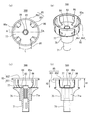
- FIGS. 6A, 6B, 6C, and 6D are plan views of the second head member 80
- FIG. 6B is a cross-sectional view taken along line BB of FIG. 6A (a side cross-sectional view of the second head member 80)
- FIG. (C) is the perspective view which looked at the 2nd head member 80 from diagonally upward
- FIG.6 (d) is the perspective view which looked at the 2nd head member 80 from diagonally downward.
- the second head member 80 includes, for example, a facing portion 82 and a peripheral edge of the facing portion 82.
- An annular wall 81 extending downward from the peripheral portion, a pressing portion 85 extending upward from the peripheral edge of the opposing portion 82, and an enclosure wall 87 extending downward from the opposing portion 82 inside the annular wall 81. I have.
- the facing portion 82 includes a flat plate-like portion 82a disposed to face the primary discharge port 73 of the first head member 70.
- the plate-like portion 82a has a discharge port 83 for discharging bubbles. Is formed.
- the facing portion 82 further includes a nozzle forming wall 84 that stands upward from the plate-like portion 82a, and a projection 88 that protrudes downward from the plate-like portion 82a inside the surrounding wall 87.
- an opening penetrating vertically is formed in a portion inside the nozzle forming wall 84 in plan view.
- the opening at the tip of the nozzle forming wall 84 constitutes a discharge port 83. That is, the lower space and the upper space of the facing portion 82 communicate with each other through the opening of the plate-like portion 82a, the internal space of the nozzle forming wall 84, and the discharge port 83.
- the height of the pressing portion 85 is larger than the height of the nozzle forming wall 84.
- the height of the pressing portion 85 is the protruding length of the pressing portion 85 from the plate-like portion 82a, and is also the height difference between the upper surface of the plate-like portion 82a and the upper end of the pressing portion 85.
- the height of the nozzle forming wall 84 is the protruding length of the nozzle forming wall 84 from the plate-like portion 82a, and is also the height difference between the upper surface of the plate-like portion 82a and the upper end of the nozzle forming wall 84. That is, the pressing portion 85 extends from the discharge port 83 in the opposite direction (upward) to the pressing direction by the pressing operation.
- the discharge port 83 is formed at the tip of the nozzle forming wall 84 that stands up in the opposite direction, and the pressing portion 85 extends from the discharge port 83 in the opposite direction.
- the pressing portion 85 stands high.
- the planar shapes of the nozzle forming wall 84 and the discharge port 83 are not particularly limited.
- the planar shape of the nozzle forming wall 84 and the discharge port 83 is circular, circular bubbles can be discharged.
- the planar shape of the nozzle forming wall 84 and the discharge port 83 is non-circular, bubbles having a shape corresponding to the planar shape can be discharged. That is, the nozzle forming wall 84 and the discharge port 83 are formed in a shape corresponding to the target shape of the foam.
- the discharge port 83 is not limited to one (single) opening, but may be an aggregate of a plurality of openings independent from each other.
- the shapes of the nozzle forming wall 84 and the discharge port 83 are not necessarily the same as the target shape of the bubbles.
- the discharge port 83 has a non-circular shape or includes a plurality of openings.
- the discharge port 83 including a plurality of openings means that the discharge port 83 includes a plurality of openings arranged independently of each other.
- the discharge port 83 shapes and discharges bubbles into a predetermined target shape.
- shaping the bubbles into a predetermined target shape means shaping the bubbles into a non-circular shape. Therefore, the bubbles discharged from the discharge port 83 are formed in a predetermined target shape, and the bubbles have a non-circular shape.
- the bubble having a non-circular shape means that the shape of the bubble in a plan view is non-circular.
- the non-circular shape here does not include a single circular shape, but includes a shape in which a plurality of circular shapes are gathered and a predetermined target shape described below.
- Examples of the predetermined shape of the bubble include a triangle, a rectangle, a diamond, a star, a heart shape of a playing card, a clover shape, a spade shape, an animal such as a rabbit, a cat, an elephant, and a bear, and a game character.
- Examples include a shape simulating the contour of a part of the body such as the face, a shape simulating the contour of a vehicle such as a flower or plant, its fruit, an airplane, an automobile, or a yacht.
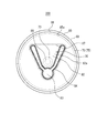
- the predetermined target shape of the foam (the shape of the foam shaped article 150 (FIG. 8)) is a shape that imitates a rabbit (a kite).
- the nozzle forming wall 84 and the discharge port 83 are, for example, a circular portion that discharges foam forming a rabbit face portion (except the ear), and a rabbit ear that extends from the circular portion. And two long portions to be formed.
- the discharge port 83 has one (single) opening.
- the planar shape of the plate-like part 82a is not particularly limited, for example, it is circular as shown in FIG.
- the pressing portion 85 and the annular wall 81 are each formed in an annular shape in plan view.
- the axial centers of the pressing portion 85 and the annular wall 81 are orthogonal to the plate-like portion 82a.
- the annular wall 81 and the pressing portion 85 are formed to have the same diameter, and are continuous vertically. Therefore, the whole of the annular wall 81 and the pressing portion 85 forms one annular portion (cylindrical portion).
- the upper end surface of the pressing part 85 is formed in an annular shape in plan view, and is disposed flat and horizontally.
- the pressing portion 85 has an upright portion at a position spaced outward from the discharge port 83.
- the press part 85 has a communication part which connects the area
- the pressing portion 85 is formed with one or a plurality of holes 86, and the holes 86 are communication portions.
- holes 86 are formed at four locations at equal angular intervals (90-degree intervals) in the circumferential direction of the pressing portion 85. The hole 86 penetrates the inside and outside of the pressing portion 85, and communicates the inner region and the outer region of the pressing portion 85 with each other.
- the pressing portion 85 is formed in a standing wall shape surrounding the discharge port 83, and the hole 86 that allows the inner region and the outer region of the pressing portion 85 to communicate with each other.
- the standing portion of the pressing portion 85 is configured as a continuous wall that circulates around the discharge port 83, but the present invention is not limited to this example, and the standing portion of the pressing portion 85. May be constituted by a plurality of wall portions intermittently arranged around the discharge port 83.
- the first head member 70 and the second head member 80 are assembled by, for example, the annular wall 75 of the first head member 70 and the annular wall 81 of the second head member 80 being fitted to each other, and the foam discharge head. 300.
- the first head member 70 and the second head member 80 are assembled to each other by fitting the annular wall 75 into the annular wall 81.
- the tip (upper end) of the annular wall 75 is in contact with the lower surface of the plate-like portion 82a and the tip of the surrounding wall 87
- the (lower end) is in contact with the upper surface of the primary plate 74 in a circular shape. That is, the lower end of the surrounding wall 87 is horizontally arranged over the entire area.
- the primary plate-like portion 74 and the plate-like portion 82a face each other in parallel, for example.
- the opening 75 a of the annular wall 75 is closed by the facing portion 82 provided in the second head member 80.
- the projection 88 is formed in a columnar shape (for example, a cylindrical shape with a rounded tip (lower end)), and is disposed coaxially with the cylindrical portion 71.
- the tip of the projection 88 is the primary discharge. It enters into the exit 73.
- the internal space of the cylindrical portion 71 is in communication with the internal space of the surrounding wall 87 via the primary discharge port 73. That is, the internal space of the cylinder portion 71 is in communication with the internal space of the nozzle forming wall 84.
- the pump unit 120 includes a piston guide 140 formed in a cylindrical shape.
- the piston guide 140 holds a ball valve 190 at its upper end.
- the foam discharge head 300 pushes the cylindrical portion 71 of the foam discharge head 300 into the upright cylindrical portion 113 from above the upright cylindrical portion 113 and inserts and fixes the upper end portion of the piston guide 140 to the lower end portion of the cylindrical portion 71.
- the piston guide 140 is mounted.
- the piston guide 140 is fixed to the cylindrical portion 71 of the foam discharge head 300 by, for example, fitting.
- the piston guide 140 is disengaged from the cylindrical portion 71 so that the foam discharge head 300 can be removed from the cap 90.
- the piston guide 140 is supported by the case of the pump unit 120 via an urging member such as a coil spring.
- an urging member such as a coil spring.
- the pressing operation of the foam discharge head 300 stops at a predetermined bottom dead center.
- the foam discharge head 300 and the piston guide 140 are raised to the top dead center position (the position shown in FIGS. 1 to 4) according to the urging force of the urging member. ing.
- the foam discharge container 100 is configured to discharge a certain amount of foam by a single pressing operation on the foam discharge head 300 (operation for pressing the foam discharge head 300 from the top dead center to the bottom dead center).
- the piston member 140 and the foam discharge head 300 are fixed to each other, whereby the ring member 60 (the ring member 60 includes the mesh holding ring 50) is disposed above the ball valve 190. Therefore, the arrangement region of the ball valve 190 communicates with the internal space of the cylindrical portion 71 above the holding portion 72 via the internal space of the ring member 60 and the mesh holding ring 50, and consequently the upper end of the cylindrical portion 71.
- the former mechanism 20 including the gas-liquid mixing unit 21 communicates with the primary discharge port 73 via the internal space of the cylindrical portion 71.
- the surrounding wall 87 is formed in a closed loop shape in plan view.
- a region that is an interval between the primary plate-like portion 74 and the opposing portion 82 and is surrounded by the surrounding wall 87 is referred to as an anterior chamber 30.
- Bubbles generated by the former mechanism 20 are discharged into the front chamber 30 through the cylindrical portion 71 and the primary discharge port 73 at the upper end thereof, spread into the front chamber 30, and upward from the discharge port 83 of the facing portion 82. It is designed to be discharged.
- the foam discharge container 100 includes a primary discharge port 73 for discharging bubbles, a front chamber 30 in which bubbles discharged from the primary discharge port 73 spread in the internal space, and a primary discharge port 73 with the front chamber 30 interposed therebetween. And a facing portion 82 that is disposed so as to face the discharge port 83.
- the facing portion 82 is the entire portion constituting the ceiling surface of the front chamber 30 and is disposed at least inside the surrounding wall 87 in plan view.
- the opposing portion 82 is the entire region excluding the discharge port 83 in the region inside the annular portion (cylindrical portion) configured by the entirety of the annular wall 81 and the pressing portion 85 in plan view. And is also present in a region outside the surrounding wall 87 in plan view.
- the surrounding wall 87 is accommodated inside the pressing portion 85 and the discharge port 83 and the primary discharge port 73 are accommodated inside the surrounding wall 87 in a plan view.
- the foam discharge container 100 includes a primary plate-like portion 74 having a primary discharge port 73 for discharging bubbles, a front chamber 30 in which bubbles discharged from the primary discharge port 73 spread in the internal space, and the front chamber 30 in between. And a facing portion 82 that is disposed to face the primary discharge port 73 with a discharge port 83 formed therebetween.
- the facing portion 82 is configured to include a plate-like portion 82a that is disposed to face the primary plate-like portion 74 with the front chamber 30 interposed therebetween and in which a discharge port 83 is formed.
- the front chamber 30 is an area surrounded by the surrounding wall 87 standing between the primary plate-like portion 74 and the plate-like portion 82a, and when the foam discharge container 100 is viewed in the pressing direction, the pressing portion 85.
- the enclosure wall 87 is accommodated inside the enclosure wall 87, and the discharge port 83 and the primary discharge port 73 are contained inside the enclosure wall 87.
- the range in which the foam spreads in the front chamber 30 can be limited. It is possible to discharge from 83. As described above, since the foam discharge container 100 discharges a certain amount of foam by a single pressing operation, a limited amount of foam can be reliably discharged from the discharge port 83.
- the surrounding wall 87 is one configuration of the second head member 80, and the surrounding wall 87 rises (hangs down) from the plate-like portion 82 a toward the primary plate-like portion 74.
- the surrounding wall 87 may be one configuration of the first head member 70, and in this case, the surrounding wall 87 has a structure in which the surrounding wall 87 stands from the primary plate-like portion 74 toward the plate-like portion 82a.
- the surrounding wall 87 should just be the shape where the inner peripheral surface of the surrounding wall 87 surrounds the discharge outlet 83 (and inner peripheral surface of the nozzle formation wall 84) in planar view. From the viewpoint of limiting the range of the front chamber 30 as much as possible, as shown in FIG.
- the inner peripheral surface of the surrounding wall 87 surrounds the discharge port 83 (and the inner peripheral surface of the nozzle forming wall 84) with a substantially shortest distance. Preferably it is.
- the inner peripheral surface of the surrounding wall 87 (the whole or part of the inner peripheral surface of the surrounding wall 87) is preferably formed on the inner side of the outer peripheral surface of the nozzle forming wall 84.
- a part of the inner peripheral surface of the surrounding wall 87 is disposed along a part of the outer peripheral surface of the nozzle forming wall 84 in plan view, and the part of the inner peripheral surface of the surrounding wall 87 is The nozzle forming wall 84 is disposed inside the part of the outer peripheral surface.
- the inner peripheral surface of the surrounding wall 87 may coincide with the outline of the discharge port 83 in plan view. That is, the surrounding wall 87 and the discharge port 83 may be formed in the same size and shape in plan view, and may be arranged to overlap each other.
- the height dimension of the front chamber 30 is 20% of the height dimension of the nozzle forming wall 84 from the viewpoint of limiting the amount of foam filling the front chamber 30 and improving the three-dimensional formability of the foam having a specific shape. Preferably, it is at least 30% or more, preferably 120% or less, and more preferably 100% or less.
- the facing portion 82 includes the protruding portion 88 that protrudes downward from the plate-like portion 82a.
- the tip end portion of the protruding portion 88 enters the primary discharge port 73.
- the facing portion 82 includes a protrusion 88 that protrudes toward the primary discharge port 73, and when the foam discharge container 100 is viewed in the pressing direction, the protrusion 88 is at least of the primary discharge port 73. It overlaps with a part. Therefore, when the foam discharge container 100 is viewed in the pressing direction, the facing portion 82 covers at least a part of the primary discharge port 73.
- the facing portion 82 may cover the entire primary discharge port 73 or may cover a part of the primary discharge port 73.
- the facing portion 82 covers at least a part of the primary discharge port 73 when the foam discharge container 100 is viewed in the pressing direction, the foam discharged from the primary discharge port 73 is applied to the facing portion 82 and spread.
- the foam can be shaped and discharged into a predetermined target shape by the discharge port 83. For this reason, it is possible to sufficiently spread bubbles throughout the discharge port 83. Therefore, it becomes easier to shape the foam into a predetermined target shape with more certainty.
- the protrusion 88 since the protrusion 88 protrudes toward the primary discharge port 73, the bubbles discharged from the primary discharge port 73 can be spread more reliably by hitting the protrusion 88. In particular, since the protrusion 88 has entered the primary discharge port 73, the protrusion 88 can spread bubbles more reliably.
- the foam discharge container 100 is configured as described above.
- the foam ejection head 300 In a normal state where the foam ejection head 300 is not pressed down, the foam ejection head 300 exists at the top dead center position (FIGS. 1 to 4).
- the pressing operation on the foam discharge head 300 is a state in which the opening 85a at the upper end of the foam discharge head 300 (the upper end of the pressing portion 85) is closed with the discharge target 40 such as a hand (that is, the discharge target 40).
- the pressing operation with respect to the foam discharge head 300 can be performed with one hand operation.
- the foam discharge head 300 and the piston guide 140 are lowered relative to the container body 10 against the urging force of the urging member in the pump unit 120.
- the liquid agent 101 and air are supplied to the gas-liquid mixing unit 21 by the action of the pump unit 120, and bubbles are generated in the gas-liquid mixing unit 21.
- the bubbles generated in the gas-liquid mixing unit 21 pass through the mesh 51 to become finer and more uniform bubbles.
- the bubbles generated in the former mechanism 20 in this manner pass through the inside of the cylindrical portion 71 and are discharged from the primary discharge port 73 to the front chamber 30 and spread in the front chamber 30.
- the bubbles pass through the nozzle forming wall 84 formed in the facing portion 82 and are discharged from the discharge port 83.
- the foam is shaped into a predetermined target shape (a shape simulating a rabbit in the present embodiment), and adheres to the lower surface of the discharge target body 40 blocking the opening 85a. . That is, the foam that has popped out of the discharge port 83 by the pressing operation of the pressing portion 85 is transferred to the discharge target body 40, and the foam shaped article 150 that is a foam shaped into a predetermined target shape adheres to the lower surface of the discharge target body 40. It becomes a state.
- the piston guide 140 and the foam ejection head 300 are raised according to the urging force of the urging member, and the foam ejection head 300 returns to the top dead center position. Thereafter, the object to be ejected 40 is lifted above the opening 85a and turned upside down, so that the foamed article 150 is formed on the object to be ejected 40 as shown in FIG. That is, the foam molded article 150 having a predetermined target shape can be received on the discharged body 40.
- the piston guide 140 rises, the liquid agent 101 in the container body 10 is sucked into the pump unit 120 through the dip tube 130.
- the press part 85 since the press part 85 has the standing part which stood up in the position spaced apart outward from the discharge outlet, the foam discharge head 300 can be stably pressed by the pressing operation of the press part 85. it can.
- the pressing portion 85 surrounds the periphery of the discharge port 83, by pressing the discharged body 40 against the upper end surface of the pressing portion 85 and pushing down the pressing portion 85 by the discharged body 40, The foam discharge head 300 can be pushed down stably.
- the entire upper end surface of the pressing portion 85 is disposed flat and horizontally. That is, the entire front end surface (upper end surface) of the pressing portion 85 is disposed at the same position in the pressing direction (vertical direction) by the pressing operation. Therefore, the pressing operation with respect to the foam discharge head 300 can be performed more stably.
- the operation of pressing the foam ejection head 300 is performed at a speed of 30 mm / s from the viewpoint of smoothly ejecting the foam from the ejection port 83 and stably forming a specific shape of foam on the ejection target 40 such as a hand.
- the pressing force when the foam discharge head 300 is pushed down is preferably 1N or more, more preferably 5N or more, further preferably 40N or less, and further preferably 35N or less.
- the pressing portion 85 is formed with a hole 86 that allows the inner region and the outer region of the pressing portion to communicate with each other. Therefore, even when the opening 85 a is sealed by the discharged body 40 when the pressing operation is performed on the foam discharge head 300, the air inside the pressing portion 85 is smoothly transferred to the outside of the pressing portion 85 through the hole 86. Can be discharged. Therefore, since the pressing operation of the foam discharge head 300 can be performed with a lighter force, the foam discharge head 300 can be smoothly pressed and the bubbles can be discharged from the discharge port 83. In addition, since the bubbles can be smoothly discharged, the bubbles having a specific shape can be suitably formed into a desired three-dimensional shape.
- the foam expands in the front chamber 30 arranged in front of the discharge port 83 and the front chamber 30 is filled with the foam, the foam can be discharged from the discharge port 83. It becomes easy to spread sufficiently, and it becomes easy to form bubbles in a predetermined target shape by the discharge ports 83.
- the facing portion 82 is arranged, bubbles discharged from the primary discharge port 73 are easily spread in the front chamber 30.
- cap 90 including the pump unit 120
- the structure and operation of the cap 90 are merely examples, and the structure of the cap 90 may be other widely known structures without departing from the gist of the present invention. There is no problem even if a thing is applied to this embodiment.
- the foam discharge container 100 is opened in the direction opposite to the pressing direction by the pressing operation and discharges the bubbles, and the discharge target 40 and the discharge openings 83 are provided. And a pressing portion 85 that maintains a constant distance. Therefore, by performing a pressing operation on the pressing portion 85 by the discharged body 40 such as a hand, bubbles discharged from the discharge ports 83 can be attached to the discharged body 40. Therefore, it is possible to receive the foam on the discharged body 40 such as a hand by one-hand operation. That is, since the foam can be received on the discharge target body 40 by a simple operation, the convenience of the foam discharge container 100 is improved.
- the distance between the discharge target 40 and the discharge port 83 can be maintained constant by the pressing portion 85, the bubbles discharged from the discharge port 83 are not crushed by the discharge target 40, and the discharge target 40 is not damaged. Can be received. Therefore, in particular, when the foam is shaped into a predetermined target shape and discharged, it becomes easier to form the target shape on the discharged body 40 more accurately. That is, the foam processability by the foam discharge container 100 is improved. Further, since the discharge port 83 is formed at the tip of the nozzle forming wall 84, the bubbles can be stably discharged in the direction opposite to the pressing direction by the pressing operation. The pressing portion 85 extends in the opposite direction beyond the discharge port 83 formed at the tip of the nozzle forming wall 84, so that bubbles can be suitably received on the discharge target body 40.
- the height dimension of the pressing portion 85 is preferably at least twice the height dimension of the nozzle forming wall 84 so that the foam model 150 can be suitably received on the discharged body 40. It is further preferably 3 times or more, more preferably 10 times or less, and still more preferably 8 times or less. Further, the height difference between the discharge port 83 and the pressing portion 85 is preferably 5 mm or more and 20 mm or less, and more preferably 7 mm or more and 18 mm or less. Further, the height dimension of the nozzle forming wall 84 is preferably 1 mm or more, more preferably 2 mm or more, from the viewpoint of favorably receiving bubbles from the discharge port 83 onto the discharge target body 40.
- the structure of the former mechanism 20 such as the pump portion 120 and the height dimension of the pressing portion 85 and the nozzle forming wall 84 are set so as to protrude upward.
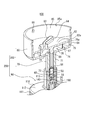
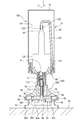
- the foam discharge container 100, the foam discharge cap 200, and the foam discharge head 300 which concern on 2nd Embodiment are demonstrated using FIG.9 and FIG.10.
- the foam ejection container 100, the foam ejection cap 200, and the foam ejection head 300 according to the present embodiment are the points described below, and the foam ejection container 100, the foam ejection cap 200, and the foam ejection head according to the first embodiment described above.
- the configuration is the same as the foam ejection container 100, the foam ejection cap 200, and the foam ejection head 300 according to the first embodiment.
- the pressing part 85 of the foam ejection head 300 has a notch-shaped part 89 formed at the upper end as a communicating part instead of having the hole 86.
- the notch-shaped portion 89 has a shape that is recessed downward from a non-formation region of the notch-shaped portion 89 at the upper end of the pressing portion 85.
- the number of the notch-shaped portions 89 may be one or more, but in the case of the present embodiment, as shown in FIGS. 9 and 10, a plurality of (for example, eight) plural (for example, eight) at equal angular intervals in the circumferential direction of the pressing portion 85.
- a notch-shaped portion 89 is formed.
- the foam discharge container 100 has a notch-shaped portion 89 as a communication portion that allows the inner region and the outer region of the pressing portion 85 to communicate with each other.
- the foam discharge container 100, the foam discharge cap 200, and the foam discharge head 300 which concern on 3rd Embodiment are demonstrated using FIGS. 11-13.
- the shapes of the discharge port 83 and the nozzle forming wall 84 are the same as the foam discharge container 100, the foam discharge cap according to the first embodiment.
- 200 and the foam ejection head 300, and the other configurations are the same as the foam ejection container 100, the foam ejection cap 200, and the foam ejection head 300 according to the first embodiment.
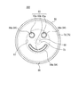
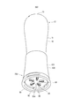
- the foam model 150 includes two first portions 150 a that imitate human eyes, and one second portion 150 b that imitates the mouth of a laughed person, (A shape imitating a human smile).
- the discharge port 83 and the nozzle forming wall 84 correspond to the foam model 150 having such a shape, and the discharge port 83 includes a plurality of openings.
- the foam discharge container 100, the foam discharge cap 200, and the foam discharge head 300 have a plurality of nozzle forming walls 84 corresponding to the respective openings.
- the second head member 80 includes, as the nozzle forming wall 84, for example, two first wall portions 84a each having a circular planar shape and one second wall portion 84b having a circular planar shape.
- the discharge port 83 is configured to include two first portions 83a each having a circular opening in a planar shape, and a second portion 83b having one opening having a circular shape in a planar shape.
- Each first portion 83a is formed at the tip of each first wall portion 84a
- the second portion 83b is formed at the tip of the second wall portion 84b.
- a foam discharge container, a foam discharge cap, and a foam discharge head 300 according to a fourth embodiment will be described with reference to FIGS. 14 to 16.
- the foam discharge container, the foam discharge cap, and the foam discharge head 300 according to this embodiment are the same as the foam discharge container 100, the foam discharge cap 200, and the foam discharge head 300 according to the first embodiment described above.
- the bubble discharge container 100, the bubble discharge cap 200, and the bubble discharge head 300 according to the first embodiment are configured in the same manner.
- the foam discharge container, the foam discharge cap, and the foam discharge head 300 do not have the surrounding wall 87.
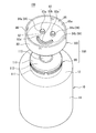
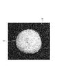
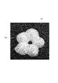
- the foam model 150 has a shape simulating a snowman as shown in FIG.
- the discharge port 83 and the nozzle forming wall 84 correspond to the foam model 150 having such a shape
- the discharge port 83 includes a plurality of openings.
- the foam discharge container 100, the foam discharge cap 200, and the foam discharge head 300 have a plurality of nozzle forming walls 84 corresponding to the respective openings. That is, the second head member 80 has, for example, a first wall portion 84a and a second wall portion 84b having a circular planar shape as the plurality of nozzle forming walls 84, respectively.
- the plane area of the internal space of the first wall portion 84a is larger than the plane area of the internal space of the second wall portion 84b. Note that the distance between the first wall 84 a and the primary discharge port 73 is smaller than the distance between the second wall 84 b and the primary discharge port 73.
- the discharge port 83 includes a first portion 83a and a second portion 83b each having an opening having a circular planar shape.
- the first portion 83a is formed at the tip of the first wall portion 84a, and the second portion 83b is formed at the tip of the second wall portion 84b.
- the plane area of the first part 83a is larger than the plane area of the second part 83b.
- the distance between the first portion 83a and the primary discharge port 73 is smaller than the distance between the second portion 83b and the primary discharge port 73.
- first wall portion 84a and the first portion 83a are arranged so as to partially overlap the primary discharge port 73 in a plan view
- the second wall portion 84b and the second portion 83b are, for example, in a plan view. It arrange
- FIG. Further, in plan view, the first wall portion 84a and the first portion 83a, and the second wall portion 84b and the second portion 83b are disposed on opposite sides with the center of the primary discharge port 73 interposed therebetween. Yes.
- the facing portion 82 includes an inhibition guide wall 180 formed so as to protrude downward from the plate-like portion 82 a.
- the inhibition guide wall 180 is formed so as to protrude downward from a half of the first wall portion 84a near the primary discharge port 73 in a plan view, and the planar shape of the inhibition guide wall 180 is a semicircle. It is arcuate. That is, the inhibition guide wall 180 is formed in a semi-cylindrical shape.
- the inhibition guide wall 180 having such a shape and arrangement serves as an inhibition portion that inhibits bubbles discharged from the primary discharge port 73 to the front chamber 30 from flowing toward the first wall portion 84a and the first portion 83a.
- the inhibition guide wall 180 having such a shape and arrangement serves as a guide portion that guides the foam discharged from the primary discharge port 73 into the front chamber 30 toward the second wall portion 84b and the second portion 83b. Also serves as a function.
- the discharge port 83 is configured to include the first discharge region (first portion 83a) and the second discharge region (second portion 83b), and the foam discharge container is disposed from the primary discharge port 73 to the front chamber 30. And a bubble that is discharged from the primary discharge port 73 to the front chamber 30 to the second discharge region.
- the guidance part it is constituted by inhibition guidance wall 180 to guide are provided. That is, by inhibiting the bubbles from flowing into the first portion 83a by the inhibition guide wall 180, it is possible to suppress the amount of foam discharged from the first portion 83a from becoming excessive.
- FIG. In other words, of the first portion 83a and the second portion 83b, while suppressing the amount of foam discharged from the first portion 83a closer to the discharge port 183 and having a larger plane area (opening area) from being excessive, It is possible to suppress the amount of foam discharged from the second portion 83b far from the discharge port 183 and having a small flat area (opening area) from being excessively small.
- the inhibition guide wall 180 has a function of adjusting the flow of bubbles from the primary discharge port 73 to the front chamber 30 and a function of adjusting the flow of bubbles from the front chamber 30 to the discharge port 83.
- the inclined wall surface 181 (that is, the outer surface of the semi-cylindrical inhibition guide wall 180), which is the wall surface on the second wall portion 84b and the second portion 83b side, is increased as it goes upward. It inclines so that the 2 wall part 84b and the 2nd part 83b side may be approached. For this reason, the inclined wall surface 181 can effectively guide the bubbles discharged from the primary discharge port 73 into the front chamber 30 toward the second wall portion 84b and the second portion 83b.
- a part of the inhibition guide wall 180 overlaps the primary discharge port 73 in plan view. That is, a part of the inhibition guide wall 180 is disposed at a position facing the primary discharge port 73.
- the position where the inhibition guide wall 180 is disposed is not limited to the position facing the primary discharge port 73.
- the tip (lower end) of the inhibition guide wall 180 does not reach the upper surface of the primary plate-like portion 74, and is positioned above the upper surface of the primary plate-like portion 74.
- the opening area of the first discharge region (first portion 83a) is larger than the opening area of the second discharge region (second portion 83b) has been described.
- the magnitude relationship between the opening area of the one ejection region and the opening area of the second ejection region is not particularly limited.
- the opening area of the first ejection region and the opening area of the second ejection region may be equal to each other, or the opening area of the second ejection region may be larger than the opening area of the first ejection region.
- the example in which the first discharge region (first portion 83a) is disposed closer to the primary discharge port 73 than the second discharge region (second portion 83b) has been described.
- the relationship between the distance between the first discharge region and the primary discharge port 73 and the distance between the second discharge region and the primary discharge port 73 is not particularly limited.
- the distance between the first discharge region and the primary discharge port 73 and the distance between the second discharge region and the primary discharge port 73 may be equal to each other, or more than the distance between the first discharge region and the primary discharge port 73.
- the distance between the second discharge region and the primary discharge port 73 may be smaller.
- the shapes of the first discharge region (first portion 83a) and the second discharge region (second portion 83b) are not limited to the above example.
- the first discharge region is the second discharge region.
- the foam discharge container may include one or both of the inhibition unit and the guide unit.
- the second discharge region has a tendency that the smaller the opening area, the farther it is arranged from the primary discharge port 73, and the smaller the second discharge region, the smaller the bubble discharge amount.
- the example in which the first discharge region and the second discharge region are openings (the first portion 83a and the second portion 83b) that are separated from each other has been described. That is, the example in which the discharge port 83 is an aggregate of a plurality of openings has been described.
- the present invention is not limited to this example, and the first discharge region and the second discharge region may be connected to each other through a connection opening that is narrower than the first discharge region and the second discharge region. Good. That is, the first discharge region and the second discharge region may be configured by a part of one opening.
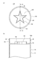
- FIG. 17A is a plan view of a foam discharge head (head member 170) according to the fifth embodiment
- FIG. 17B is a cross-sectional view taken along line BB of FIG. 17A.
- the foam discharge container and the foam discharge cap according to the present embodiment are different from the foam discharge container 100 and the foam discharge cap 200 according to the first embodiment in that the foam discharge container and the foam discharge cap according to the present embodiment include a foam discharge head described below.
- the configuration is the same as the foam discharge container 100 and the foam discharge cap 200 according to the first embodiment.
- the foam discharge head is constituted by a head member 170 shown in FIGS. 17 (a) and 17 (b). That is, in the present embodiment, the foam discharge head is constituted by one member.
- the head member 170 has a cylindrical cylindrical portion 171, a plate-shaped portion 182 provided on the inner peripheral side of the upper end portion of the cylindrical portion 171, and a discharge port 183 formed in the plate-shaped portion 182.
- the plate-like portion 182 includes a discharge port forming wall 184 that rises upward from a flat plate-like portion of the plate-like portion 182, and is provided at the tip (upper end) of the discharge port forming wall 184.
- a discharge port 183 is formed.
- the planar shapes of the discharge port 183 and the discharge port forming wall 184 are not particularly limited, but are, for example, a star shape as shown in FIG.
- the cylinder part 171 corresponds to the cylinder part 71 in the first embodiment.
- the head member 170 pushes the cylindrical portion 171 into the upright cylindrical portion 113 from above with respect to the cap member 110, and the upper end portion of the piston guide 140 with respect to the lower end portion of the cylindrical portion 171.
- the piston guide 140 is attached.
- the head member 170 further includes a pressing portion 185 that rises upward from the periphery of the plate-shaped portion 182 and a hole 86 formed in the pressing portion 185.
- the pressing part 185 extends upward from the discharge port 183.
- An opening 185 a is formed at the upper end of the pressing portion 185.
- the planar shape of the pressing part 185 matches, for example, the planar shape of the cylindrical part 171.
- the discharge port forming wall 184 is housed inside the pressing portion 185 in plan view.
- the foam discharge head does not have a configuration corresponding to the front chamber 30 (enclosure wall 87), the primary discharge port 73, the protrusion 88, the primary plate-like portion 74, the annular wall 75, and the annular wall 81. .
- a foam discharge container, a foam discharge cap, and a foam discharge head become a simple structure.
- the foam generated by the former mechanism 20 is squeezed by the plate-like portion 182 and the discharge port forming wall 184 and discharged from the discharge port 183.
- an object to be ejected such as a hand is disposed at the upper end of the pressing portion 185, and a pressing operation is performed on the foam ejection head, whereby the object to be ejected has a predetermined target shape (for example, a star shape).
- a foam model can be attached.
- FIG. 10 a foam discharge container, a foam discharge cap, and a foam discharge head according to the sixth embodiment will be described with reference to FIG.
- the foam discharge container and the foam discharge cap according to the present embodiment are different from the foam discharge container and the foam discharge cap according to the fifth embodiment described above in that the foam discharge head and the foam discharge cap described below are provided.
- the foam discharge container and the foam discharge cap according to the fifth embodiment are configured in the same manner.
- the foam discharge head is constituted by a head member 170 shown in FIG. That is, also in this embodiment, the foam discharge head is composed of one member.
- the head member 170 in the present embodiment is different from the head member 170 in the fifth embodiment in the points described below, and in other points, the head member 170 in the fifth embodiment is different from the head member 170 in the fifth embodiment. It is constituted similarly.
- the plate-like portion 182 protrudes outward (around) from the upper end of the cylindrical portion 171.
- the discharge port forming wall 184 surrounds a wider range than the primary discharge port 171a at the upper end of the cylindrical portion 171 in plan view.
- a mesh 177 is provided at the upper end of the discharge port forming wall 184. Therefore, bubbles that have passed through the mesh 177 are discharged from the discharge port 183 at the upper end of the discharge port forming wall 184.
- the foam generated by the former mechanism 20 is subjected to pressure loss due to the mesh 177, the foam is discharged from the primary discharge port 171a at the tip of the cylindrical portion 171 and is then the internal space of the discharge port forming wall 184. It spreads into the front chamber 30 and is discharged from the discharge port 183. Therefore, the bubbles can be shaped into a predetermined target shape (for example, the same star shape as in the fifth embodiment) and discharged by the discharge port forming wall 184 and the discharge port 183. Further, the bubbles can be made finer and more uniform by passing through the mesh 177 when the bubbles are discharged from the discharge port 183.
- a predetermined target shape for example, the same star shape as in the fifth embodiment
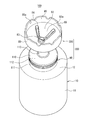
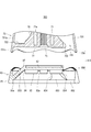
- FIGS. 20A is a plan view of the bubble discharge head 300
- FIG. 20B is a perspective view of the bubble discharge head 300
- FIG. 20C is a bubble along the line AA in FIG. 20A
- FIG. 20D is a sectional view of the ejection head 300
- FIG. The bubble discharge head 300 according to the present embodiment is different from the bubble discharge head 300 according to the first embodiment in the points described below. In other respects, the bubble discharge head 300 is different from the first embodiment. It is comprised similarly to the foam discharge head 300 which concerns.
- the nozzle forming wall 84 of the foam discharge head 300 has a circular shape when viewed in the pressing direction (FIG. 20A). That is, the planar shape of the nozzle forming wall 84 is circular.
- the foam discharge head 300 includes a single nozzle forming wall 84. For this reason, in the case of this embodiment, as shown, for example in FIG. 21, the circular foam 151 can be formed.
- the circular foam discharged to the discharge target body 40 is referred to as a foam 151 in distinction from the non-circular foam model.
- the foam discharge head 300 is configured by two members, the first head member 70 and the second head member 80, has been described.
- the head 300 is composed of a single member.
- the foam discharge head 300 includes, for example, a cylindrical portion 71 and a cylindrical portion 71. And a table-like portion 77 provided at the upper end portion of the head.
- the upper surface of the base 77 is formed flat.
- the foam discharge head 300 further includes a nozzle forming wall 84 projecting upward from the upper surface of the base portion 77, and an outer portion extending downward from the base portion 77 and disposed around the upper portion 71 a of the cylindrical portion 71.
- the nozzle forming wall 84 is disposed, for example, in the central portion of the base portion 77.
- the internal space of the cylindrical portion 71 communicates with the internal space of the nozzle forming wall 84, and the cylindrical portion 71 supplies bubbles to the internal space of the nozzle forming wall 84.
- the cylindrical portion 71 and the nozzle forming wall 84 are arranged coaxially with each other.
- the internal space of the cylindrical portion 71 communicates directly with the internal space of the nozzle forming wall 84.
- the foam discharge head 300 does not have the above-described front chamber 30.
- the inner diameter of the outer cylinder part 76 is set to be larger than the outer diameter of the cylinder part 71.
- the foam discharge head 300 further includes a pressing portion 85 erected upward from the peripheral edge portion on the upper surface of the base portion 77.
- the pressing portion 85 includes a plurality of (for example, four) columnar portions 851 that are disposed intermittently (for example, at equal angular intervals) in the circumferential direction of the upper surface of the table-shaped portion 77, and these columnar portions 851. And an annular portion 852 that is disposed on the upper side.
- the annular portion 852 is disposed horizontally and connects the upper ends of the columnar portions 851 to each other.
- the columnar portion 851 is an upright portion in the pressing portion 85.
- the height position of the lower end of the hole 86 is set to be lower than the height position of the upper end of the nozzle forming wall 84 (FIGS. 19, 20C, and 20D). ). Therefore, even if the foam discharge container 100 is disposed in an environment where shower water (hot water) or the like is applied, the water accumulated on the upper surface of the base 77 does not flow into the nozzle forming wall 84, and the hole 86. It is smoothly discharged to the outside through. More specifically, in the case of the present embodiment, the height position of the lower end of the hole 86 is set to be equal to the height position of the upper surface of the base 77 (FIGS. 19, 20C, and 20). d)). Thereby, even if the foam discharge container 100 is disposed in an environment where water (hot water) of the shower is applied, the water is smoothly discharged to the outside through the hole 86, so that It can suppress that water accumulates.
- the height dimension H2 of the hole 86 (FIG. 20 ( d)) is preferably 50% or more of the height H1, for example. Thereby, water can be more smoothly smoothly discharged to the outside through the hole 86. Further, from the viewpoint of sufficiently securing the structural strength of the pressing portion 85, the height dimension H2 of the hole 86 (FIG. 20D) is preferably 95% or less of the height H1.
- the height H1 is also the standing height of the pressing portion 85.
- the total length of the region where the holes 86 are arranged in the circumferential direction of the pressing portion 85 is set in a range of 50% or more of the circumferential length of the pressing portion 85, More preferably, it is set in the range of 60% or more. That is, the length four times the length L shown in FIG. 20A is 50% or more of the circumferential length of the pressing portion 85. Thereby, water can be more smoothly smoothly discharged to the outside through the hole 86. Further, from the viewpoint of sufficiently ensuring the structural strength of the pressing portion 85, the total length of the region where the hole 86 is disposed is set to a range of 95% or less of the circumferential length of the pressing portion 85. preferable.
- the foam discharge container 100 and the foam discharge cap 200 according to the present embodiment include the foam discharge head 300 shown in FIGS. 19, 20 (a), 20 (b), 20 (c), and 20 (d). In this respect, it is different from the foam discharge container 100 and the foam discharge cap 200 according to the first embodiment. In other respects, the foam discharge container 100 and the foam discharge cap 200 according to the first embodiment described above. It is configured in the same way.
- the pressing operation with respect to the foam discharge head 300 is performed by pressing the foam discharge head 300 with the discharge target 40 while the discharge target 40 such as a hand is placed on the upper surface of the annular portion 852.
- a foam discharge container 100 according to an eighth embodiment will be described with reference to FIG. In FIG. 22, in the foam discharge cap 200, only the outline is shown for the portion below the break line H ⁇ b> 4 and above the break line H.
- the foam discharge container 100 according to the present embodiment is different from the foam discharge container 100 according to the seventh embodiment in the points described below. In other points, the foam discharge container 100 is different from the seventh embodiment. It is comprised similarly to the foam discharge container 100 which concerns.
- the dip tube 130 is bent, and the tip 131 of the dip tube 130 is located near the upper end of the body 11, for example. Thereby, as shown in FIG. 22, the tip 131 of the dip tube 130 can be immersed in the liquid 101 in the container body 10 in a state where the foam discharge container 100 is turned upside down.
- the base end 132 of the dip tube 130 is a cylindrical tube holding portion 129 formed at the lower end of the pump portion 120 (the upper end of the pump portion 120 when the foam discharge container 100 is turned upside down as shown in FIG. 22). It is fixed to.
- the foam discharge cap 200 includes the dip tube 130 that supplies the liquid 101 in the container body 10 to the pump unit 120, and the suction port at the tip 131 of the dip tube 130 is the container body with the discharge port 83 facing downward. 10 is located below the liquid level of the liquid 101 in the liquid crystal.
- the downward direction is the direction of gravity.
- the pressing operation on the foam discharge head 300 is performed by turning the container main body 10 in a state where the foam discharge container 100 is turned upside down and the annular portion 852 is applied to the discharge target body 40. This is done by pushing down (in the direction of gravity). That is, the pressing operation on the foam discharge head 300 of the foam discharge container 100 according to the present embodiment presses the container main body 10 in the direction toward the discharge target body 40 with the pressing portion 85 applied to the discharge target body 40. Is done. By the pressing operation, the foam passes through the nozzle forming wall 84 and is discharged from the discharge port 83.
- the bubbles popping out from the discharge port 83 are transferred to the discharge target body 40, and the foam 151, which is a bubble shaped in a circular shape as shown in FIG.
- the discharge target body 40 may be anything as long as it has an upward upper surface.
- a table or a floor can be used as the discharge target body 40.
- the foam body 151 (FIG. 21) is placed on the other hand (the discharged object 40). Can also be discharged.
- the container body 10 is gripped with one hand, and the pressing portion 85 is held with the other hand positioned below in a state where the annular portion 852 of the pressing portion 85 is applied to the other hand (discharged body 40) positioned below.
- a pressing operation on the foam discharge head 300 of the foam discharge container 100 may be performed.
- the discharge target 40 and the discharge port 83 are maintained in a separated state from the start stage to the end stage of the pressing operation.
- the foam discharge container 100 includes the container main body 10 that stores the liquid agent 101, and the foam discharge cap 200 that is attached to the container main body 10 and discharges the foam according to the pressing operation. While having the discharge port 83 and the press part 85, when the container main body 10 moves to a press direction relatively with respect to the press part 85, the liquid agent 101 is produced
- the foam discharge container 100 is in a state where the discharge port 83 faces downward and the pressing portion 85 (the annular portion 852) is in contact with the placement surface as shown in FIG. It can be independent. Therefore, the foam discharge container 100 can be stored in the posture shown in FIG. The downward direction here is also the direction of gravity.
- the foam discharge container 100 is used in the direction shown in FIG. 19 (the discharge port 83 is upward).
- the tip 131 of the dip tube 130 can be immersed in the liquid 101 both when used in the upside down direction (the discharge port 83 faces downward) shown in FIG.
- the foam discharge container 100 can be used for both of these directions.
- the tip 131 of the dip tube 130 is immersed in the liquid 101 even when the foam discharge container 100 is used in another direction (for example, horizontal direction (horizontal direction)) where the discharge port 83 is neither up nor down.
- the foam model 150 can be attached to a vertical wall surface (a wall surface perpendicular to the placement surface or the floor).
- the foam discharge container 100 is a normal inverted foam discharge container that can be used both in the upright state in which the discharge port 83 is upward and in the inverted state in which the discharge port 83 is downward. Since the foam discharge container 100 is a vertically inverted foam discharge container, the pressing unit 85 (foam discharge head 300 is pressed) by pressing the pressing unit 85 or the container body 10 while the pressing unit 85 is in contact with the discharge target body 40. ) And the container body 10 can be brought close to each other, so that bubbles discharged from the discharge port 83 can be attached to the discharge target body 40.
- FIGS. 23-26 are a perspective view of the foam ejection head 300
- FIG. 25 (b) is a side view of the foam ejection head 300
- FIG. 25 (c) is the foam ejection head 300 along the line AA in FIG. FIG.
- the foam discharge container 100 according to the present embodiment is different from the foam discharge container 100 according to the eighth embodiment described above in that it includes a foam discharge head 300 described below. It is comprised similarly to the foam discharge container 100 which concerns on said 8th Embodiment.
- the bubble discharge head 300 according to the present embodiment is different from the bubble discharge head 300 according to the first embodiment (FIGS. 3, 4, and 7) in the points described below.
- the configuration is the same as that of the foam ejection head 300 according to the first embodiment.
- the first head member 70 of the foam discharge head 300 includes a cylindrical portion 71, A cylindrical portion 77 provided at the upper end of the cylindrical portion 71, an annular wall 75 standing upward from the peripheral edge of the cylindrical portion 77, and extending downward from the cylindrical portion 77, An outer cylinder portion 76 disposed around the upper portion 71a.
- the downward direction is the direction of gravity in a state where the bottom 14 of the foam discharge container 100 contacts the mounting surface and the foam discharge container 100 is self-supporting.
- a primary discharge port 73 is formed at the upper end of the cylindrical portion 71.
- the upper surface of the base 77 is formed flat.
- the pressing portions 85 of the second head member 80 of the foam discharge head 300 are arranged intermittently (for example, at equiangular intervals) in the circumferential direction of the upper surface of the plate-like portion 82a (for example, at equal angular intervals). 4) columnar portions 851 and an annular portion 852 arranged on the upper side of these columnar portions 851.
- the annular portion 852 is disposed horizontally and connects the upper ends of the columnar portions 851 to each other.
- the height position of the lower end of the hole 86 of the second head member 80 of the foam discharge head 300 is set lower than the height position of the upper end of the nozzle forming wall 84 (FIG. 25B). ), FIG. 25 (c)). Therefore, even if the foam discharge container 100 is arranged in an environment where water (hot water) or the like of the shower is applied, the water accumulated on the upper surface of the plate-like portion 82a does not flow into the nozzle forming wall 84, but the hole 86. It is smoothly discharged to the outside through. More specifically, in the case of the present embodiment, the height position of the lower end of the hole 86 is set equal to the height position of the upper surface of the plate-like portion 82a (FIGS.
- the height dimension H2 of the hole 86 (FIG. 25 ( For example, b)) is preferably 50% or more of the height H1, and more preferably 60% or more. Thereby, water can be more smoothly smoothly discharged to the outside through the hole 86.
- the total length of the region where the holes 86 are arranged in the circumferential direction of the pressing portion 85 is in a range of 50% or more of the circumferential length of the pressing portion 85. It is preferably set, and more preferably 60% or more. Thereby, water can be more smoothly smoothly discharged to the outside through the hole 86. Further, from the viewpoint of sufficiently ensuring the structural strength of the pressing portion 85, the total length of the region where the hole 86 is disposed is set to a range of 95% or less of the circumferential length of the pressing portion 85. preferable.
- the pressing operation on the foam discharge head 300 is performed with the container body 10 in a state where the annular portion 852 is applied to the discharge target body 40 as shown in FIG. This is done by pushing down.
- the foam is shaped into a predetermined target shape by passing through the nozzle forming wall 84 and adheres to the discharge target body 40.
- the bubbles that have popped out from the discharge port 83 are transferred to the discharge target body 40, and as shown in FIG. 26, the foam model 150, which is a foam shaped into a predetermined target shape, is attached to the discharge target body 40. .
- the foam model 150 has a shape imitating a flower.
- the discharge port 83 and the nozzle forming wall 84 correspond to the foam model 150 having such a shape.
- the discharge port 83 includes a plurality of (for example, five) openings 831.
- the second head member 80 of the foam ejection head 300 has a plurality of nozzle forming walls 84 corresponding to the openings 831.
- the openings 831 of each nozzle forming wall 84 have a planar shape simulating petals, and these openings 831 are arranged radially.
- the foam model 150 has a shape imitating a flower by integrating the bubbles discharged from the openings 831.
- the foam discharge head 300 having the structure described in the ninth embodiment is a foam discharge container 100 of a type in which the foam discharge head 300 is pushed down by the discharge target body 40 in the same manner as the foam discharge container 100 according to the first embodiment.
- the foam discharge head 300 is a foam discharge container 100 of a type in which the foam discharge head 300 is pushed down by the discharge target body 40 in the same manner as the foam discharge container 100 according to the first embodiment.
- it is applicable.
- the user can hold the container body 10 and use the foam discharge container 100 as in the eighth and ninth embodiments.
- the foam discharge container 100 includes a container main body 10 that stores the liquid agent 101, and a foam discharge cap 200 that is attached to the container main body 10 and discharges bubbles in response to a pressing operation. 83 and a pressing unit 85, and a pump unit that generates the liquid 101 from the discharge port 83 and discharges the bubbles from the discharge port 83 when the container body 10 moves in the pressing direction relative to the pressing unit 85.
- the container body 10 is a pressing portion that is gripped and pressed by a user during a pressing operation.
- the pressing operation of the foam discharge container 100 according to the present embodiment on the foam discharge head 300 is performed by pressing the container body 10 in the direction toward the discharge target body 40 with the pressing portion 85 applied to the discharge target body 40. Done.
- the pressing portion 85 contacts the placement surface with the discharge port 83 facing downward. It can stand on its own.
- the downward direction is the direction of gravity.
- the foam discharge cap 200 includes a dip tube 130 that supplies the liquid agent 101 in the container body 10 to the pump unit 120, and the discharge port 83.
- the suction port of the tip 131 of the dip tube 130 is positioned below the liquid surface of the liquid 101 in the container body 10.
- the downward direction is the direction of gravity.
- the foam discharge container 100 according to the present embodiment is different from the foam discharge container 100 according to the ninth embodiment in the points described below, and the other points are the same as those in the ninth embodiment. It is comprised similarly to the foam discharge container 100 which concerns.
- the portion (the top portion 15 in the present embodiment) opposite to the discharge port 83 in the foam discharge container 100 is formed as a portion that is not placed on the placement surface, that is, a non-placement portion. Yes.
- the top portion 15 of the container body 10 when the foam discharge container 100 is self-supported in a state where the pressing portion 85 is in contact with the placement surface is formed in a convex shape toward the outside of the container body 10.
- it is formed in a curved surface shape that is convex toward the outside of the container body 10, and more preferably is formed in a convex hemispherical shape toward the upper side.
- the top part 15 which is a part on the opposite side to the discharge port 83 in the foam discharge container 100 is a non-mounting part in which the foam discharge container 100 cannot stand by itself in a posture where the top part 15 contacts the ground. ing. Since the top portion 15 is hemispherical, for example, the container body 10 is gripped so as to wrap the top portion 15 by hand, and an operation of moving the container body 10 in the pressing direction relative to the pressing portion 85 as the operation portion. It can be suitably performed.
- the shape of the top portion 15 is not limited to a hemispherical shape, and may be a shape having an inclined surface, a conical shape, a quadrangular pyramid shape, or the like.
- the foam discharge cap 200 includes a cap 90 and a foam discharge head 300.
- the structure of the cap 90 is the same as that in each of the above embodiments.
- the foam discharge container 100 has a configuration in which the discharge port 83 faces downward as shown in FIG. 27 in a normal installation state (cap 90 and the like). Also, the positional relationship between the components is upside down with respect to the above embodiments.
- the foam discharge head 300 includes a first head member 70 and a second head member 80.
- the first head member 70 includes a cylindrical portion 71, a base-shaped portion 77, a primary discharge port 73, and an outer cylindrical portion 76, as in the ninth embodiment.
- the first head member 70 does not include the annular wall 75 (FIG. 23).
- the connection structure between the first head member 70 and the cap 90 is the same as that in the ninth embodiment.
- the first head member 70 includes a plurality of (for example, three) connecting portions 702 that extend radially from the outer peripheral portion of the platform 77 and the connecting portions 702. And a second outer cylinder portion 701 connected to the base portion 77.
- the second outer cylinder portion 701 is formed in a cylindrical shape (for example, substantially cylindrical shape), and covers the periphery of the outer cylinder portion 76, the periphery of the standing cylinder portion 113, and the periphery of at least the lower portion of the mounting portion 111. ing.
- the second outer cylinder part 701 includes an upper part 701 a located above the base part 77 and the connection part 702, and a lower part 701 b located below the base part 77 and the connection part 702.
- a gap between adjacent connecting portions 702 forms an opening 705 that allows the internal space of the lower portion 701b and the internal space of the upper portion 701a to communicate with each other.
- the second head member 80 includes a facing portion 82 (a plate-like portion 82a, a nozzle forming wall 84, a discharge port 83) and a surrounding wall 87, as in the ninth embodiment. ing.
- the surrounding wall 87 is inclined, for example, and is reduced in diameter upward.
- the second head member 80 does not include the protruding portion 88 (FIG. 23), the annular wall 81 (FIG. 23), and the hole 86 (FIG. 23) formed in the pressing portion 85. .
- the second head member 80 includes a plurality (for example, three) of connecting portions 853 that radially extend from the outer peripheral portion of the plate-like portion 82a of the facing portion 82 to the periphery,
- the plate-like portion 82a and the pressing portion 85 are connected to each other via a connecting portion 853.
- the pressing portion 85 is formed in a cylindrical shape (for example, a substantially cylindrical shape), and is disposed so as to surround the periphery of the facing portion 82 in plan view.
- each connection part 853 is arrange
- the distal end of the connecting portion 853 (the connecting end of the connecting portion 853 and the pressing portion 85) is disposed at a lower position than the base end of the connecting portion 853 (the connecting end of the connecting portion 853 and the plate-like portion 82a).
- the pressing portion 85 includes a portion located above the tip of the connecting portion 853 and a portion located below the tip of the connecting portion 853.
- the gap between the adjacent connecting portions 853 is a region below the connecting portion 853 in the internal space of the pressing portion 85 and a space above the connecting portion 853 in the internal space of the pressing portion 85 or the second outer cylinder portion 701. It is an opening 854 that allows the region to communicate with each other.
- At least the lower part of the foam discharge cap 200 when the foam discharge container 100 is self-supported in a state where the pressing portion 85 is in contact with the placement surface is formed in a shape that spreads at the bottom.
- the bubble discharge cap 200 is expanded in diameter toward the pressing direction.
- the foam discharge container 100 can stand more stably in the posture of FIG.
- at least the lower part (for example, the part including the lower part of the upper part 701a and the lower part 701b) of the second outer cylinder part 701 has a shape that spreads out from the bottom. That is, at least the lower part of the second outer cylinder part 701 gradually increases in diameter toward the lower side.
- the pressing part 85 also has a hem-expanding shape (the diameter gradually increases downward (pressing direction)).
- the outer peripheral surface of the foam discharge cap 200 has a continuous curved surface shape from the second outer cylinder portion 701 to the pressing portion 85, and a portion including the lower portion of the second outer cylinder portion 701 and the pressing portion 85 is a skirt. It is spreading.
- the lower end edge of the second outer cylinder portion 701 and the upper end edge of the pressing portion 85 are fitted to each other in the fitting portion 410, so that the first head member 70, the second head member 80, Are connected to each other.
- the upper end of the surrounding wall 87 is in contact with or close to the lower surface of the table-like portion 77, and the plate-like portion 82a and the table A front chamber 30 surrounded by a surrounding wall 87 is formed between the shaped portion 77.
- an engaging portion 704 is continuously formed at the lower end edge of the second outer cylinder portion 701 over the entire area in the circumferential direction of the lower end edge, and the upper end edge of the pressing portion 85 is
- the engagement portion 856 is continuously formed over the entire area in the circumferential direction of the upper edge.
- the engaging portion 704 and the engaging portion 856 are each formed with a step, and the step of the engaging portion 704 and the step of the engaging portion 856 are engaged with each other. 856 is fitted.
- the engaging portion 704 and the engaging portion 856 are each formed in a waveform that undulates in the vertical direction.
- the waveform shape of the engaging portion 704 and the waveform shape of the engaging portion 856 are the lower end edge of the second outer cylinder portion 701 and the upper end edge of the pressing portion 85. In the circumferential direction, the contact is continuously made without a gap. A portion where the engaging portion 704 and the engaging portion 856 are in close contact with each other is formed in a waveform as shown in FIG. Further, the upper end portion 701c of the second outer cylinder portion 701 is also formed in a waveform as shown in FIG.
- the corrugated shape of the upper end portion 701c of the second outer cylinder portion 701 is a shape in which the corrugated positions of the engaging portion 704 and the engaging portion 856 coincide with the positions of the irregularities. Further, the second head member 80 is restricted from rotating relative to the first head member 70 in the circumferential direction.
- the connecting portion 702 and the connecting portion 853 are formed in the same planar shape, and the connecting portion 702 and the connecting portion 853 are in a state where the first head member 70 and the second head member 80 are connected. They overlap each other. Therefore, the opening 854 and the opening 705 have the same planar shape, and the opening 854 and the opening 705 overlap each other in a state where the first head member 70 and the second head member 80 are connected. It is like that.
- the region below the connecting portion 853 in the internal space of the pressing portion 85 is located above the connecting portion 853 in the internal space of the pressing portion 85 and the second outer cylinder portion 701 via the plurality of openings 854. Communicate with the area.
- the region above the connecting portion 853 in the internal space of the pressing portion 85 and the second outer cylindrical portion 701 is above the connecting portion 702 in the internal space of the second outer cylindrical portion 701 via the plurality of openings 705. Communicate with the territory.
- the region above the connecting portion 702 in the internal space of the second outer cylinder portion 701 is located via a gap 703 between the inner peripheral surface of the upper end portion 701c of the second outer cylinder portion 701 and the outer peripheral surface of the mounting portion 111.
- the foam discharge container 100 communicates with the external space.
- the outer peripheral surface of the mounting portion 111 and the inner peripheral surface of the upper end portion 701c of the second outer cylinder portion 701 are close to each other.
- the container body 10 has a cylindrical mouth and neck portion, and the mounting portion 111 is attached to the periphery of the mouth and neck portion by screwing with the mouth and neck portion. ing.
- the container body 10 has the mouth and neck portion
- the foam discharge cap 200 includes the cylindrical mounting portion 111 that is mounted on the mouth and neck portion in a state of surrounding the mouth and neck portion, and the pressing portion 85.
- a cylindrical portion (second outer cylinder portion 701) that extends toward the container body 10 and covers the periphery of the mounting portion 111 or the container body 10.
- the pressing portion 85 is an annular standing wall that surrounds the periphery of the discharge port 83 and rises in the opposite direction (downward in the present embodiment) from the discharge port 83.
- the internal space of the pressing portion 85 is a foam discharge container through the internal space of the cylindrical portion (second outer cylindrical portion 701) and the gap 703 between the inner peripheral surface of the cylindrical portion and the outer peripheral surface of the mounting portion 111. It communicates with 100 external spaces. For this reason, when foam is discharged from the discharge port 83, the atmosphere (air) in the internal space of the pressing portion 85 is changed between the internal space of the tubular portion (second outer tubular portion 701) and the inner periphery of the tubular portion. It is possible to easily escape to the external space of the foam discharge container 100 via the gap 703 between the surface and the outer peripheral surface of the mounting portion 111. Therefore, bubbles can be discharged more smoothly from the discharge port 83.
- the foam discharge cap 200 includes a cylindrical portion (second outer cylinder portion 701), so that the self-supporting state of the foam discharge container 100 is stabilized and the design is excellent.
- the gap 703 is formed between the inner peripheral surface of the cylindrical portion (second outer cylindrical portion 701) and the outer peripheral surface of the mounting portion 111 has been described.
- the gap 703 may be formed between the inner peripheral surface of the cylindrical portion (second outer cylindrical portion 701) and the outer peripheral surface of the trunk portion 11 of the container main body 10, or You may form between the outer peripheral surface of both the trunk
- the gap 703 is not so narrow that the mounting portion 111 and the second outer cylinder portion 701 are guided to each other when the container body 10 is operated in the pressing direction.
- the present invention is not limited to this example, and the gap 703 is formed narrower.
- the mounting portion 111 and the second outer cylinder portion 701 are guided to each other. It may be like this.
- the container main body 10 has the mouth and neck portion, and the foam discharge cap 200 is pressed against the cylindrical mounting portion 111 attached to the mouth and neck portion in a state of surrounding the mouth neck portion.
- a cylindrical portion (second outer cylindrical portion 701) that extends from the portion 85 toward the container body 10 side and is arranged coaxially with the mounting portion 111.
- the mounting portion 111 may be configured to guide each other.
- the container main body 10 and the foam discharge are caused by the outer peripheral surface of the mounting portion 111 and the outer peripheral surface of the second outer cylindrical portion 701 having a larger diameter than the inner peripheral surface of the outer cylindrical portion 76 and the outer peripheral surface of the upright cylindrical portion 113.
- the cylindrical portion (second outer cylindrical portion 701) is disposed around the container main body 10 coaxially with the container main body 10, and the cylindrical portion and the container main body 10 are guided to each other during the pressing operation. May be.
- the tubular portion and the container body 10 may be guided together, and the tubular portion and the mounting portion 111 may be guided together.
- the liquid agent discharge container 500, the liquid agent discharge cap 600, and the liquid agent discharge head 700 according to the eleventh embodiment will be described with reference to FIGS.
- the front structure is shown for the portion between the break line H5 and the break line H6 in the container body 10 and the liquid agent discharge cap 600.
- the liquid agent discharge container 500 is in a posture in which the discharge port 83 faces downward as shown in FIG. 30 in a normal installation state.
- the downward direction is the direction of gravity.
- a liquid agent discharge container 500 is a liquid agent discharge container 500 that discharges a liquid agent according to a pressing operation, and is a container main body 10 that stores the liquid agent 101, and a liquid agent that is attached to the container main body 10 and is attached to the container main body 10 according to the pressing operation. And a liquid agent discharge cap 600 that discharges 101.
- the liquid agent discharge cap 600 is opened in a direction opposite to the pressing direction by the pressing operation and is a pressure that maintains a constant distance between the discharge port 83 that discharges the liquid agent 101 and the discharge target 40 that receives the liquid agent 101 and the discharge port 83.
- a pump unit 120 that discharges the liquid agent 101 from the discharge port 83 when the container body 10 moves in the pressing direction relative to the pressing unit 85.
- the container main body 10 is an operation part hold
- the description of the same definitions as in the above embodiments will be omitted. According to this embodiment, it is possible to receive the liquid agent on the discharged body such as a hand by one-hand operation.
- the container body 10 In a state where the user holds the container body 10 and presses the pressing portion 85 against the upper surface of the discharge target body 40, the container body 10 is operated as an operation portion to move downward relative to the pressing portion 85.
- the liquid agent 101 can be discharged from the discharge port 83 onto the discharge target body 40.
- this operation is performed by pressing the container body 10 in the direction toward the discharged body 40 in a state where the pressing portion 85 is applied to the discharged body 40.
- the to-be-discharged body 40 and the discharge outlet 83 are maintained in a separated state from the start stage to the end stage of the pressing operation.
- the pump unit 120 since the liquid agent discharge container 500 discharges the liquid agent 101 in a liquid state, the pump unit 120 is different from the hand-operated foam pump described in each of the above embodiments, and is a hand-operated liquid pump. It is. Further, the liquid agent discharge container 500 does not include the former mechanism 20.
- the liquid agent discharge cap 600 includes a cap 90 including the pump unit 120 and a liquid agent discharge head 700 attached to the cap 90. When the liquid agent discharge head 700 is pushed into the container main body 10 side, the pump unit 120 causes the liquid agent 101 to be discharged from the discharge port 83 in a liquid state.
- the structure of the liquid pump (pump unit 120) is well known, and detailed description thereof is omitted in this specification.
- the direction of the discharge port 83 when discharging the liquid agent 101 is not limited to the downward direction.
- 101 can be attached to a downward surface, a mounting surface, a wall surface perpendicular to the floor, or the like.
- a conditioner can be cited as a representative example of the liquid 101, but is not limited thereto, and is not limited thereto, but is a beauty agent such as a cleaning agent or skin care cream, a gel sanitizer, a toilet gel stamp, or a hair cosmetic.
- a beauty agent such as a cleaning agent or skin care cream, a gel sanitizer, a toilet gel stamp, or a hair cosmetic.
- various foods for example, edible oils and fats such as mayonnaise and margarine, creams, etc.
- liquid form fluid state
- the cap 90 for example, penetrates the mounting portion 111 mounted on the mouth and neck of the container body 10, the annular portion 421 mounted on the lower side of the mounting portion 111, the mounting portion 111 and the annular portion 421.
- a standing tube portion 113 protruding downward and a cylindrical portion 422 protruding further downward from the standing tube portion 113 are provided.
- a liquid agent discharge head 700 is attached to the lower end portion of the cylindrical portion 422.
- the liquid agent discharge container 500 is a so-called delamination container
- the container body 10 includes an outer shell 16 made of a hard synthetic resin, and an outer shell 16. And an inner bag 17 accommodated inside the bag.
- the outer shell 16 includes a trunk portion 11, a shoulder portion 12, a top portion 15, and a mouth and neck portion.
- the liquid agent 101 is accommodated in the inner bag 17.
- the tip 131 of the dip tube 130 is located inside the inner bag 17.
- the container body 10 includes an introduction portion 18 for introducing outside air between the inner peripheral surface of the outer shell 16 and the outer surface of the inner bag 17.
- the inner bag 17 When the liquid agent 101 is discharged from the liquid agent discharge container 500 and the liquid agent 101 stored in the inner bag 17 is reduced, the inner bag 17 is deflated and peeled from the outer shell 16 from the inner bag 17, and through the introduction part 18. Thus, outside air is introduced between the inner peripheral surface of the outer shell 16 and the outer surface of the inner bag 17. Inflow of outside air into the inner bag 17 is substantially prevented.
- the liquid agent ejection head 700 is configured by assembling three members, for example, a first head member 440, a second head member 80, and a third head member 430.
- the first head member 440 includes a plate-like portion 441 that is a flat plate-like portion having a circular shape in plan view, an inner cylinder portion 442 that rises upward from the center portion of the plate-like portion 441, and an inner cylinder portion 442. And an outer cylinder part 443 which is arranged coaxially with the inner cylinder part 442 and rises upward from the center part of the plate-like part 441.
- a hole penetrating the inner cylinder portion 442 and the plate-like portion 441 is formed in the center portion of the first head member 440, and the lower end of the hole is a primary discharge port 73.
- the second head member 80 includes a facing portion 82 having a plate-like portion 82a.
- the facing portion 82 further includes a nozzle forming wall 84 having a discharge port 83.
- the second head member 80 further includes a pressing portion 85 extending downward from the peripheral portion of the plate-like portion 82a, a fitting wall 857 having a circular shape in plan view standing upward from the peripheral portion of the plate-like portion 82a, An enclosing wall 87 standing upward from the upper surface of the plate-like portion 82a inside the fitting wall 857.
- a region surrounded by the surrounding wall 87 is the anterior chamber 30.
- the liquid agent 101 is discharged into the front chamber 30 through the primary discharge port 73, spreads into the front chamber 30, and is discharged from the discharge port 83.
- the discharge port 83 is disposed in the inner region of the surrounding wall 87.
- One or more (for example, two as shown in FIG. 32) holes 86 are formed in the pressing portion 85.
- the discharge port 83 is configured to include a plurality of openings. Each opening has a non-circular shape. As an example, as shown in FIG. 32, the discharge port 83 is configured by a plurality of openings arranged radially, and the shape of the liquid agent 101 discharged from the discharge port 83 becomes a shape imitating a petal. It has become. However, the shape of the discharge port 83 may be other shapes. In addition, the discharge port 83 may be configured by a single opening, and the shape of the opening may be a non-circular shape. In this case, the liquid agent 101 discharged from the discharge port 83 has a predetermined target shape. Can be formed.
- the liquid agent 101 discharged from the discharge port 83 is formed in a predetermined target shape.
- the discharge port 83 shapes and discharges the liquid agent into a predetermined target shape, as in the first embodiment.
- the discharged liquid agent 101 is a liquid agent shaped article formed in a predetermined target shape.
- the present invention is not limited to this example, and the liquid agent 101 discharged from the discharge port 83 may have a circular shape, or may have another unspecified shape. .
- the viscosity of the liquid agent 101 in the container main body 10 is 1000 mPa ⁇ s or more and 100000 mPa ⁇ s or less at 20 ° C.
- the viscosity of the liquid agent 101 at 20 ° C. is more preferably 10000 mPa ⁇ s or more and 80000 mPa ⁇ s or less, and further preferably 30000 mPa ⁇ s or more and 60000 mPa ⁇ s or less.
- the viscosity of the liquid 101 is measured with a B-type viscometer.
- an appropriate rotor or spindle is selected according to the dosage form and viscosity of the liquid 101, and the rotor or spindle is rotated at a rotation speed corresponding to the rotation speed (50 to 60 rotations / minute).
- the viscosity at the time when the rotation time reaches 60 seconds can be measured.
- the viscosity of the liquid agent 101 is 1000 mPa ⁇ s or more and 100000 mPa ⁇ s or less at 20 ° C.
- the liquid agent 101 discharged from the discharge port 83 can be suitably formed into a predetermined target shape.
- the third head member 430 includes a tubular (for example, substantially cylindrical) tubular portion 431 and an annular inner flange portion 432 projecting inward from the inner peripheral surface of the tubular portion 431.
- An opening 432 a is formed in the inner flange portion 432.
- the inner flange portion 432 is disposed at a position spaced upward from the lower end of the tubular portion 431.
- the plate-like portion 441 of the first head member 440 and the fitting wall 857 of the second head member 80 are formed in the cylindrical portion 431 of the third head member 430 below the inner flange portion 432.
- the first head member 440 and the second head member 80 are assembled to the third head member 430, and the liquid agent discharge head 700 is configured.
- the lower end portion of the cylindrical portion 422 of the cap 90 is press-fitted into the gap between the outer peripheral surface of the inner cylindrical portion 442 of the first head member 440 and the inner peripheral surface of the outer cylindrical portion 443, so that the first The head member 440, and thus the entire liquid agent discharge head 700, is fixed to the cap 90.
- the outer shape of the liquid agent discharge container 500 according to the present embodiment is generally the same as the outer shape of the foam discharge container 100 according to the tenth embodiment.
- the liquid agent discharge container 500 can be self-supporting with the discharge port 83 facing downward and the pressing portion 85 contacting the placement surface.
- the top portion 15 of the container body 10 when the liquid agent discharge container 500 is self-supported in a state where the pressing portion 85 is in contact with the placement surface is formed in a convex hemispherical shape upward.
- At least the lower part of the liquid agent discharge cap 600 when the liquid agent discharge container 500 is self-supporting in a state where the pressing portion 85 is in contact with the placement surface is formed in a shape that spreads from the bottom. More specifically, at least the lower part of the cylindrical part 431 and the pressing part 85 have a hem-expanding shape (the diameter gradually increases downward). And the outer peripheral surface of the liquid agent discharge cap 600 becomes a continuous curved surface shape from the cylindrical part 431 to the press part 85, and the part containing the lower part of the cylindrical part 431 and the press part 85 becomes a hem
- the upper end portion 431 a of the cylindrical portion 431 covers the periphery of the lower end portion of the trunk portion 11.
- the cylindrical portion 431 is disposed coaxially with the trunk portion 11 of the container body 10.
- the gap 703 between the inner peripheral surface of the upper end 431a and the outer peripheral surface of the lower end of the barrel 11 is such that the cylindrical portion 431 and the barrel 11 guide each other when the container body 10 is pressed.
- a narrow gap is set.
- the container body 10 has the mouth and neck
- the liquid agent discharge cap 600 includes the cylindrical mounting portion 111 that is mounted on the mouth and neck in a state of surrounding the mouth and neck, and the pressing portion 85.
- the present invention is not limited to this example, and the upper end portion 431a of the cylindrical portion 431 covers the periphery of the mounting portion 111, and the upper end portion 431a is disposed coaxially with the mounting portion 111. At this time, the cylindrical portion 431 and the mounting portion 111 may be guided together.
- the upper end portion 431a of the cylindrical portion 431 covers the periphery of the lower end portions of the mounting portion 111 and the trunk portion 11, and is arranged coaxially with the lower end portions of the mounting portion 111 and the trunk portion 11, so that the above pressing operation is performed.
- the cylindrical portion 431, the mounting portion 111, and the container body 10 may be guided together.
- the liquid agent discharge head 700 may not include the third head member 430. That is, the liquid agent ejection head 700 may be configured by assembling the first head member 440 and the second head member 80 to each other.
- air may be allowed to escape to the outside of the liquid agent discharge container 500 through the gap 703 as in the tenth embodiment.
- the container body 10 has a mouth and neck portion, and the liquid agent discharge cap 600 is formed from the cylindrical mounting portion 111 that is mounted on the mouth and neck portion in a state of surrounding the mouth and neck portion, and the pressing portion 85 to the container body.
- a cylindrical portion 431 extending toward the side 10 and covering the periphery of the mounting portion 111 or the container body 10, and the pressing portion 85 surrounds the periphery of the discharge port 83 and the discharge port 83.
- the annular standing wall, and the inner space of the pressing portion 85 is the inner space of the tubular portion 431 and the inner periphery of the tubular portion 431.
- the space may be communicated with the external space of the liquid agent discharge container 500 through a gap 703 between the surface and the mounting portion 111 or the outer peripheral surface of the container body 10.
- holes that penetrate vertically may be formed in the plate-like portion 82a and the plate-like portion 441, and the size of the gap 703 may be made sufficiently large.
- the liquid agent discharge container 500 may be a container having the container body 10 having a single-layer structure.
- the shape of the dip tube 130 may be a bent shape similar to that of the eighth to tenth embodiments, and the tip 131 may be located near the lower end of the trunk portion 11. Thereby, the tip 131 can be immersed in the liquid agent 101 with the discharge port 83 facing downward.
- the liquid agent discharge cap 600 includes a dip tube 130 that supplies the liquid agent 101 in the container main body 10 to the pump unit 120, and the suction port at the tip 131 of the dip tube 130 is in the container main body 10 with the discharge port 83 facing downward.
- the structure which is located below the liquid level of the liquid agent 101 can be employed.
- the liquid agent discharge container 500 may be a well-known pople container.
- the pople container is a container having an airless pump, and an inner tray is provided in the container body 10 having shape retention so as to be slidable up and down.
- the liquid agent 101 is accommodated in a region above the middle dish.
- the pople container is particularly preferably used when the liquid 101 has a high viscosity.
- the present invention is not limited to the above-described embodiment, and includes various modifications and improvements as long as the object of the present invention is achieved.
- the pressing portion 85 is an annular shape (the annular shape here is not limited to an annular shape, and includes, for example, a polygonal annular shape such as a square annular shape or a triangular annular shape).
- the present invention is not limited to this example, and the pressing portion 85 may be, for example, one or a plurality of rod-like bodies erected around the discharge port.
- the pressing direction by the pressing operation (the pressing direction of the foam discharge head) is downward is described, but the pressing direction by the pressing operation is not particularly limited.
- the pressing direction by the pressing operation is not particularly limited.
- the foam discharge container is a pump container using the former mechanism 20
- the present invention is not limited to this example, and the foam discharge container may be a compressed gas.
- an aerosol container in which the container body is filled with the liquid agent may be used.
- the aerosol container is preferably of a type that discharges a fixed amount of foam by a single discharge operation.
- the hole 86 that allows the inner region and the outer region of the pressing portion 85 to communicate with each other is formed in the pressing portion 85.
- the hole 86 is formed in other portions. It may be.
- the hole 86 has a region outside the surrounding wall 87 in a plan view in the plate-like portion 82a (a region where bubbles do not enter) and a region outside the surrounding wall 87 in a plan view in the primary plate-like portion 74.
- it may be formed on the annular wall 81.
- the plate-like portions 82a and 182 may be formed in a curved shape.
- the foam discharge container, the foam discharge cap, and the foam discharge head include one of the protrusion 88 or the inhibition guide wall 180 has been described. Both the portion 88 and the inhibition guide wall 180 may be provided.
- the bubble discharge container, the bubble discharge cap, and the bubble discharge head include the protrusion 88. It does not have to be.
- the container main body 10 of the foam discharge container 100 according to the first to tenth embodiments may be a delamination container, similar to the container main body 10 of the liquid agent discharge container 500 according to the eleventh embodiment. .
- a foam discharge container that discharges bubbles in response to a pressing operation, the opening being opened in a direction opposite to the operation direction of the pressing operation, a discharge port for discharging the bubbles, and a discharge target that receives the bubbles And a pressing portion that maintains a constant distance from the discharge port.
- the discharge port is formed at a tip of a nozzle forming wall standing up in the opposite direction, and the pressing portion extends from the discharge port in the opposite direction.
- the pressing portion is formed in a standing wall shape surrounding the periphery of the discharge port, and has a hole or a notch-shaped portion that allows the inner region and the outer region of the pressing portion to communicate with each other.
- ⁇ 4> A primary discharge port that discharges the bubbles, a front chamber in which the bubbles discharged from the primary discharge port spread in an internal space, and the primary discharge port with the front chamber interposed therebetween.
- the foam discharge container according to any one of ⁇ 1> to ⁇ 3>, further comprising a facing portion in which the discharge port is formed.
- a primary plate-shaped portion having a primary discharge port for discharging the bubbles, a front chamber in which the bubbles discharged from the primary discharge port spread in an internal space, and the primary discharge port with the front chamber interposed therebetween And an opposing portion in which the discharge port is formed, and the opposing portion is arranged to face the primary plate-like portion with the front chamber interposed therebetween.
- the front chamber is a region surrounded by an enclosing wall standing between the primary plate-like part and the plate-like part
- ⁇ 6> The foam discharge container according to ⁇ 4> or ⁇ 5>, in which the facing portion covers at least a part of the primary discharge port when the foam discharge container is viewed in the operation direction.
- the opposing portion is configured to include a protrusion protruding toward the primary discharge port side, and when the bubble discharge container is viewed in the operation direction, the protrusion is formed on the primary discharge port.
- the foam discharge container according to ⁇ 6> which overlaps at least a part.
- the discharge port includes a first discharge region and a second discharge region, and the foam discharge container is configured such that the bubbles discharged from the primary discharge port to the front chamber are the first discharge region.
- ⁇ 4> provided with one or both of an inhibition portion that inhibits flow to the second discharge region and a guide portion that guides the bubbles discharged from the primary discharge port to the front chamber.
- ⁇ 9> The foam discharge container according to any one of ⁇ 1> to ⁇ 8>, wherein the foam discharged from the discharge port is formed in a predetermined target shape.
- the discharge port has a non-circular shape or includes a plurality of openings.
- a foam discharge cap that is used by being attached to a container main body that stores a liquid agent, and that discharges foam in response to a pressing operation, and is open in a direction opposite to the operation direction of the pressing operation.
- a foam discharge cap comprising: a discharge port that discharges; and a pressing unit that maintains a constant distance between the discharge target that receives the bubbles and the discharge port.
- a foam discharge head that is used by being attached to a cap attached to a container body that stores a liquid agent, and that discharges bubbles in response to a pressing operation, and is open in a direction opposite to the operation direction of the pressing operation.
- a foam discharge head comprising: a discharge port that discharges the bubbles; and a pressing portion that maintains a constant distance between the discharge target that receives the bubbles and the discharge port.
- the discharge port is formed in a shape such that the bubble is shaped into the target shape when the bubble is discharged in a state where a distance between the discharge port and the discharge target body is a predetermined distance.
- the foam discharge container according to any one of the above, wherein the pressing portion maintains a distance between the discharge target and the discharge port at the predetermined distance.
- a foam discharge container for discharging bubbles in response to a pressing operation the opening being opened in a direction opposite to the pressing direction by the pressing operation, and a discharge port for discharging the bubbles, and a discharge target for receiving the bubbles And a pressing portion that maintains a constant distance from the discharge port.
- the discharge port is formed at a tip of a nozzle forming wall that stands up in the opposite direction, and the pressing portion extends from the discharge port in the opposite direction.
- the pressing portion has an upstanding portion that stands up at a position spaced outward from the discharge port, and the pressing portion includes the upstanding portion, an inner region of the pressing portion, and an outer side.
- a primary plate-like portion having a primary discharge port for discharging the bubbles, a front chamber in which the bubbles discharged from the primary discharge port spread in an internal space, and the primary discharge port with the front chamber interposed therebetween And an opposing portion in which the discharge port is formed, and the opposing portion is arranged to face the primary plate-like portion with the front chamber interposed therebetween.
- the front chamber is a region surrounded by an enclosing wall standing between the primary plate-like part and the plate-like part
- the foam discharge container according to any one of [4]. [6] The foam discharge container according to [4] or [5], wherein the facing portion covers at least a part of the primary discharge port when the foam discharge container is viewed in the pressing direction. [7] The facing portion includes a protruding portion that protrudes toward the primary discharge port side, and when the bubble discharge container is viewed in the pressing direction, the protruding portion corresponds to the primary discharge port.
- the discharge port includes a first discharge region and a second discharge region, and the foam discharge container is configured such that the bubbles discharged from the primary discharge port to the front chamber are the first discharge region.
- the foam discharge cap includes the discharge port and the pressing portion.
- a pump unit that generates the liquid agent in the bubbles by causing the container body to move in the pressing direction relative to the pressing unit and discharges the bubbles from the discharge port.
- the foam discharge container according to any one of [1] to [10], wherein the container body is an operation unit that is gripped and pressed by a user during the pressing operation.
- the foam discharge container according to [11] wherein the foam discharge container is capable of self-supporting with the discharge port facing downward and the pressing portion contacting the placement surface.
- At least a lower portion of the foam discharge cap when the foam discharge container is self-supporting in a state in which the pressing portion is in contact with the placement surface is formed in a flared shape [11] or [12]
- the top portion of the container body when the foam discharge container is self-supporting in a state where the pressing portion is in contact with the placement surface is formed in a curved surface shape that is convex toward the outside of the container body.
- the foam discharge container according to any one of [11] to [13].
- a portion of the foam discharge container opposite to the discharge port is a non-mounting portion in which the foam discharge container cannot stand by itself when the portion is in contact with the ground.
- the foam discharge container according to any one of the above.
- the foam discharge cap includes a dip tube that supplies the liquid agent in the container body to the pump unit, and the suction port at the tip of the dip tube is in the container body with the discharge port facing downward.
- the foam discharge container according to any one of [11] to [15], which is located below the liquid surface of the liquid agent.
- the container body has a mouth-and-neck portion
- the foam discharge cap includes a cylindrical attachment portion attached to the mouth-neck portion in a state of surrounding the mouth-neck portion, and the pressing portion
- a cylindrical portion that extends toward the container body and covers the periphery of the mounting portion or the container body, and the pressing portion surrounds the periphery of the discharge port and the discharge port Is an annular upright wall that stands up in the opposite direction than the inner space of the pressing portion, the inner space of the cylindrical portion, the inner peripheral surface of the cylindrical portion, the mounting portion or the
- the foam discharge container according to any one of [11] to [16], which is in communication with an external space of the foam discharge container through a gap with the outer peripheral surface of the container main body.
- the container body has a mouth-and-neck portion
- the foam discharge cap includes a cylindrical attachment portion attached to the mouth-neck portion in a state of surrounding the mouth-neck portion, and the pressing portion from the pressing portion.
- a cylindrical portion that extends toward the container main body and is disposed coaxially with the mounting portion or the container main body, and the cylindrical portion and the mounting portion or the container during the pressing operation.
- the discharge port is formed in a shape such that the bubble is shaped into the target shape when the bubble is discharged in a state where the distance between the discharge port and the discharge target body is a predetermined distance.
- the foam discharge container according to any one of [1] to [19], wherein the foam discharged from the discharge port is a foam shaped article formed in a predetermined target shape.
- the foam discharge container according to any one of [1] to [20] wherein the discharge target and the discharge port are maintained in a separated state from the start stage to the end stage of the pressing operation.
- the foamed liquid preparation includes hand soap, facial cleanser, cleansing agent, dish detergent, hair conditioner, body soap, shaving cream, skin cosmetics (foundation, cosmetic liquid, etc.), hair dye, Foam according to any one of [1] to [21], which is a disinfectant, a cream applied to food (such as bread), a household detergent, a disinfectant, or a laundry detergent (for partial washing, etc.) Discharge container.
- the foam discharge cap includes the discharge port and the pressing portion.
- the foam discharge container according to any one of [1] to [23].
- the inner peripheral surface of the surrounding wall surrounds the discharge port (and the inner peripheral surface of the nozzle forming wall) with the shortest distance in any one of [1] to [26]
- the foam discharge container as described.
- the inner peripheral surface of the surrounding wall (the whole or a part of the inner peripheral surface of the surrounding wall) is formed on the inner side of the outer peripheral surface of the nozzle forming wall. 27].
- the foam discharge container according to any one of [27].
- a height dimension of the pressing portion is two times or more, preferably three times or more, and ten times or less, preferably eight times or less of the height dimension of the nozzle forming wall.
- the foam discharge container according to any one of [1] to [28].
- the height dimension of the nozzle forming wall is 1 mm or more, preferably 2 mm or more, and 10 mm or less, preferably 8 mm or less. Any one of [1] to [30] The foam discharge container according to 1.
- a foam mechanism that foams the liquid agent is provided, and the foam discharge container squeezes the foam generated by the former mechanism by the plate-like portion and the discharge port forming wall, and discharges the foam from the discharge port.
- the foam discharge container according to any one of [1] to [32].
- a cylindrical portion that communicates with the internal space of the nozzle forming wall and supplies bubbles to the internal space of the nozzle forming wall, and the cylindrical portion and the nozzle forming wall are arranged coaxially with each other.
- the foam discharge container according to any one of [1] to [34].
- the pressing unit includes a foam discharge head that discharges foam in response to a pressing operation, and a container main body that stores the liquid agent that becomes the foam.
- the foam discharge container according to any one of [1] to [37], which is performed by pressing the container main body in a direction toward the discharge target body in a state where the pressing portion is applied to the discharge target body.
- the foam discharge container is a regular inverted foam discharge container that includes a container main body that stores a liquid agent, and can be used in both the upright state in which the discharge port is upward and the inverted state in which the discharge port is downward.
- the foam discharge container according to any one of [1] to [38].
- a foam discharge cap that is used by being attached to a container body that stores a liquid agent, and that discharges foam in response to a pressing operation, and is open in a direction opposite to the pressing direction of the pressing operation.
- a foam discharge cap comprising: a discharge port that discharges; and a pressing unit that maintains a constant distance between the discharge target that receives the bubbles and the discharge port.
- the foam discharge cap according to [40] which is used for the foam discharge container according to any one of [1] to [39].
- a foam discharge head that is used by being attached to a cap attached to a container body that stores a liquid agent, and that discharges foam in response to a pressing operation, and is open in a direction opposite to the pressing direction of the pressing operation.
- a foam discharge head comprising: a discharge port that discharges the bubbles; and a pressing portion that maintains a constant distance between the discharge target that receives the bubbles and the discharge port.
- the foam discharge head according to [42] which is used by being attached to the foam discharge cap according to [40].
- a foam discharge method in which a foam discharged from the discharge port is attached to a discharge target body by pressing to bring a relative distance between the press portion and the container body closer.
- a liquid agent discharge container that discharges a liquid agent according to a pressing operation, a container main body that stores the liquid agent, a liquid agent discharge cap that is attached to the container main body and discharges the liquid agent according to the pressing operation;
- the liquid agent discharge cap is opened in a direction opposite to the pressing direction by the pressing operation, and a distance between the discharge port for discharging the liquid agent and a discharge target for receiving the liquid agent and the discharge port is made constant.
- a pump part that discharges the liquid agent from the discharge port by moving the container body in the pressing direction relative to the pressing part.
- a liquid agent discharge container which is an operation unit that is gripped and pressed by a user during operation.
- the portion of the liquid agent discharge container opposite to the discharge port is a non-mounting portion where the liquid agent discharge container cannot stand by itself when the portion contacts the ground.
- the liquid agent discharge cap includes a dip tube that supplies the liquid agent in the container body to the pump unit, and a suction port at a tip of the dip tube is disposed in the container body with the discharge port facing downward.
- the liquid agent discharge container according to any one of [45] to [49], which is located below the liquid surface of the liquid agent.
- the container body has a mouth-and-neck portion
- the liquid agent discharge cap includes a cylindrical attachment portion attached to the mouth-neck portion in a state of surrounding the mouth-neck portion, and the pressing portion from the pressing portion.
- a cylindrical portion that extends toward the container body and covers the periphery of the mounting portion or the container body, and the pressing portion surrounds the periphery of the discharge port and the discharge port Is an annular upright wall that stands up in the opposite direction than the inner space of the pressing portion, the inner space of the cylindrical portion, the inner peripheral surface of the cylindrical portion, the mounting portion or the
- the liquid agent discharge container according to any one of [45] to [50], which communicates with an external space of the liquid agent discharge container through a gap with the outer peripheral surface of the container body.
- the container main body has a mouth-and-neck portion
- the liquid agent discharge cap includes a cylindrical attachment portion attached to the mouth-neck portion in a state of surrounding the mouth-neck portion, and the pressing portion.
- a cylindrical portion that extends toward the container main body and is disposed coaxially with the mounting portion or the container main body, and the cylindrical portion and the mounting portion or the container during the pressing operation.
- the liquid agent discharge container according to any one of [45] to [51], in which the main body guides each other.
- the liquid agent discharge container according to any one of [45] to [52] wherein the viscosity of the liquid agent in the container body is 1000 mPa ⁇ s or more and 100000 mPa ⁇ s or less at 20 ° C.
- the discharge port is formed at a tip of a nozzle forming wall that stands up in the opposite direction, and the pressing portion extends from the discharge port in the opposite direction from [45] to [45]. 55].
- the liquid agent discharge container according to any one of [55].
- the pressing portion has an upstanding portion that stands up at a position spaced outward from the discharge port, and the pressing portion includes the upstanding portion, an inner region of the pressing portion, and an outer side.
- the liquid agent discharge container according to any one of [45] to [57], further comprising a facing portion in which the discharge port is formed.
- a primary plate-like portion having a primary discharge port for discharging the liquid agent, a front chamber in which the liquid agent discharged from the primary discharge port spreads in an internal space, and the primary discharge port with the front chamber interposed therebetween And an opposing portion in which the discharge port is formed, and the opposing portion is arranged to face the primary plate-like portion with the front chamber interposed therebetween.
- the facing portion includes a protruding portion that protrudes toward the primary discharge port side, and when the liquid agent discharge container is viewed in the pressing direction, the protruding portion corresponds to the primary discharge port.
- the liquid agent discharge container according to any one of [45] to [60], wherein the liquid agent overlaps at least a part.
- the discharge port includes a first discharge region and a second discharge region, and the liquid agent discharge container has the liquid agent discharged from the primary discharge port into the front chamber. From [45], one or both of an inhibition portion that inhibits flow to the second discharge region and a guide portion that guides the liquid agent discharged from the primary discharge port to the front chamber to the second discharge region [61] The liquid agent discharge container according to any one of [61].
- the discharge port is formed in a shape such that the liquid agent is shaped to the target shape when the liquid agent is discharged in a state where the distance between the discharge port and the discharge target body is a predetermined distance.
- the liquid agent discharge container according to any one of [45] to [66] in which the discharge target and the discharge port are maintained in a separated state from the start stage to the end stage of the pressing operation.
- the height of the pressing part is at least twice the height of the nozzle forming wall, preferably at least 3 times, and at most 10 times, preferably at most 8 times.
- the height dimension of the nozzle forming wall is 1 mm or more, preferably 2 mm or more, and 10 mm or less, preferably 8 mm or less. Any one of [45] to [72]
Landscapes
- Engineering & Computer Science (AREA)
- Mechanical Engineering (AREA)
- Chemical & Material Sciences (AREA)
- Dispersion Chemistry (AREA)
- Health & Medical Sciences (AREA)
- Public Health (AREA)
- Containers And Packaging Bodies Having A Special Means To Remove Contents (AREA)
- Closures For Containers (AREA)
- Nozzles (AREA)
Abstract
泡吐出容器(100)は、押圧操作に応じて泡を吐出する泡吐出容器(100)であって、押圧操作の押圧方向に対する反対方向に開口していて泡を吐出する吐出口と、泡を受け取る被吐出体(40)と吐出口との距離を一定に維持する押圧部(85)と、を備えている。
Description
本発明は、泡吐出容器に関する。
ハンドソープ、洗顔料、食器用洗剤、整髪料などの各種の液状の材料(液剤)を空気と混合して泡にして吐出する容器(泡吐出容器)が提案されている。たとえば特許文献1には、ヘッド部が押下操作されることにより容器本体に収容された液剤を泡として吐出する泡吐出容器が記載されている。この泡吐出容器においては、三角形や五角形の頂点や中心に対応する位置に複数の円形の吐出口が離散して配置されている。この泡吐出容器は、複数の吐出口から吐出された泡が互いにくっつき合うことにより、キャラクタを模した泡造形物が形成されるように、吐出口の位置と径とが設定されている。
先行技術文献
特許文献1 特開2010-149060号公報
先行技術文献
特許文献1 特開2010-149060号公報
本発明は、押圧操作に応じて泡を吐出する泡吐出容器であって、
前記押圧操作による押圧方向に対する反対方向に開口していて、前記泡を吐出する吐出口と、
前記泡を受け取る被吐出体と前記吐出口との距離を一定に維持する押圧部と、
を備える泡吐出容器に関する。
前記押圧操作による押圧方向に対する反対方向に開口していて、前記泡を吐出する吐出口と、
前記泡を受け取る被吐出体と前記吐出口との距離を一定に維持する押圧部と、
を備える泡吐出容器に関する。
また、本発明は、押圧操作に応じて液剤を吐出する液剤吐出容器であって、
液剤を貯留する容器本体と、
前記容器本体に装着され、前記押圧操作に応じて前記液剤を吐出する液剤吐出キャップと、
を備え、
前記液剤吐出キャップは、
前記押圧操作による押圧方向に対する反対方向に開口していて、前記液剤を吐出する吐出口と、
前記液剤を受け取る被吐出体と前記吐出口との距離を一定に維持する押圧部と、
前記容器本体が前記押圧部に対して相対的に前記押圧方向に移動することにより前記吐出口から前記液剤を吐出させるポンプ部と、
を備え、
前記容器本体は、前記押圧操作の際に使用者に把持及び押圧される操作部である液剤吐出容器に関する。
液剤を貯留する容器本体と、
前記容器本体に装着され、前記押圧操作に応じて前記液剤を吐出する液剤吐出キャップと、
を備え、
前記液剤吐出キャップは、
前記押圧操作による押圧方向に対する反対方向に開口していて、前記液剤を吐出する吐出口と、
前記液剤を受け取る被吐出体と前記吐出口との距離を一定に維持する押圧部と、
前記容器本体が前記押圧部に対して相対的に前記押圧方向に移動することにより前記吐出口から前記液剤を吐出させるポンプ部と、
を備え、
前記容器本体は、前記押圧操作の際に使用者に把持及び押圧される操作部である液剤吐出容器に関する。
上述したような泡吐出容器の場合、泡を手に取るためには、片手を吐出口の下に配置した状態で、もう一方の手でヘッド部を押下する必要がある。すなわち、両手を使う必要がある。
また、液剤を泡ではなく液剤のまま吐出する液剤吐出容器についても、同様の課題がある。
本発明は、片手操作で泡を手などの被吐出体上に受け取ることが可能な泡吐出容器、泡吐出キャップ及び泡吐出ヘッドに関する。
また、本発明は、片手操作で液剤を手などの被吐出体上に受け取ることが可能な液剤吐出容器に関する。
また、本発明は、片手操作で液剤を手などの被吐出体上に受け取ることが可能な液剤吐出容器に関する。
以下、本発明の好ましい実施形態について、図面を用いて説明する。なお、すべての図面において、同様の構成要素には同一の符号を付し、重複する説明は適宜に省略する。
〔第1の実施形態〕
先ず、図1から図8を用いて第1の実施形態に係る泡吐出容器100、泡吐出キャップ200及び泡吐出ヘッド300について説明する。
なお、図1及び図3における下方向が下方、上方向が上方である。すなわち、下方向(下方)は、泡吐出容器100の底部14が載置されて泡吐出容器100が自立する状態での重力方向である。
図3では、泡吐出キャップ200において破断線Hよりも下側の部分については、外形線のみを示している。
先ず、図1から図8を用いて第1の実施形態に係る泡吐出容器100、泡吐出キャップ200及び泡吐出ヘッド300について説明する。
なお、図1及び図3における下方向が下方、上方向が上方である。すなわち、下方向(下方)は、泡吐出容器100の底部14が載置されて泡吐出容器100が自立する状態での重力方向である。
図3では、泡吐出キャップ200において破断線Hよりも下側の部分については、外形線のみを示している。
図1から図4のいずれかに示すように、泡吐出容器100は、押圧操作に応じて泡を吐出する泡吐出容器100であって、押圧操作による押圧方向(本実施形態では下方)に対する反対方向(本実施形態では上方)に開口していて泡を吐出する吐出口83と、泡を受け取る被吐出体40(例えば、図1、図8に示すように、手)と吐出口83との距離を一定に維持する押圧部85と、を備えている。従って、押圧方向に対する反対方向は、吐出口83からの吐出方向でもある。第1の実施形態において、押圧操作による押圧方向が操作方向である。
泡吐出容器100は、押圧操作に応じて泡を吐出する泡吐出ヘッド300を備えており、泡吐出ヘッド300は押圧部85を備えている。押圧部85は、吐出口83から外方向に離間した位置において起立している起立部を有している。押圧部85は、起立部を有することにより、吐出口83と被吐出体40との距離を形成する。押圧方向とは、押圧操作によって泡吐出ヘッド300が容器本体10に対して相対的に押圧される方向である。外方向とは、泡吐出ヘッド300を上面視したとき、吐出口83から、吐出口83よりも外側の位置に向かう方向である。
本実施形態では、押圧操作により泡吐出ヘッド300を押圧する方向が下方であるため、押圧操作のことを泡吐出ヘッド300の押下操作と称する場合がある。
ここで、押圧方向と、押圧方向に対する反対方向とは、必ずしも、同一直線上で180度異なる方向でなくてもよく、およそ反対方向であればよい。したがって、押圧方向と、押圧方向に対する反対方向との間には、ある程度の軸ズレ(例えば、10度以内の軸ズレ)が許容される。
また、被吐出体40と吐出口83との距離を一定に維持するとは、押圧操作の終了段階における被吐出体40と吐出口83との距離を、毎回の押圧操作において互いに一定となるようにすることであり、押圧操作の開始段階と終了段階とで被吐出体40と吐出口83との距離が変化することは許容される。例えば、毎回の押圧操作により押圧部85が一定に潰れたり又は撓んだりすることが挙げられる。ただし、押圧操作の開始段階と終了段階とで被吐出体40と吐出口83との距離が変化する場合、距離の変化量は、毎回の押圧操作において互いに一定となることが好ましい。なお、本実施形態の場合、泡吐出ヘッド300の全体が実質的に剛体であり、押圧操作の開始段階から終了段階に亘り被吐出体40と吐出口83との距離が一定に維持されるようになっている。
また、被吐出体40と吐出口83との距離を一定に維持するとは、図1及び図3等から分かるように、被吐出体40と吐出口83とが離間した状態(被吐出体40と吐出口83とが非接触の状態)に維持することである。押圧操作の開始段階から終了段階に亘り、被吐出体40と吐出口83とが離間した状態に維持される。
本実施形態によれば、片手操作で泡を手などの被吐出体上に受け取ることが可能である。
泡吐出容器100は、液剤101(図3)を貯留する容器本体10と、容器本体10に対して着脱可能に装着される泡吐出キャップ200と、を備えて構成されている。
換言すれば、泡吐出キャップ200は、泡吐出容器100の構成のうち容器本体10を除く部分により構成されている。
泡吐出キャップ200は、液剤101を貯留する容器本体10に装着して用いられ、押圧操作に応じて泡を吐出する泡吐出キャップ200であって、上述の吐出口83と押圧部85とを備えている。
換言すれば、泡吐出キャップ200は、泡吐出容器100の構成のうち容器本体10を除く部分により構成されている。
泡吐出キャップ200は、液剤101を貯留する容器本体10に装着して用いられ、押圧操作に応じて泡を吐出する泡吐出キャップ200であって、上述の吐出口83と押圧部85とを備えている。
また、泡吐出キャップ200は、容器本体10に対して着脱可能に装着されるキャップ90と、キャップ90に装着(例えば着脱可能に)して用いられる泡吐出ヘッド300と、を備えて構成されている。
換言すれば、泡吐出ヘッド300は、泡吐出キャップ200の構成のうちキャップ90を除く部分により構成されている。
泡吐出ヘッド300は、液剤101を貯留する容器本体10に装着されるキャップ90に装着して用いられ、押圧操作に応じて泡を吐出するものであり、上述の吐出口83と押圧部85とを備えている。すなわち、泡吐出ヘッド300がキャップ90に装着され、且つ、キャップ90が容器本体10に装着された状態で、泡吐出ヘッド300に対して押圧操作が行われることによって、泡吐出ヘッド300が泡を吐出する。
後述するように、泡吐出ヘッド300は、例えば、キャップ90のポンプ部120が備えるピストンガイド140の上端部に対して装着される。
本実施形態では、液剤101として、ハンドソープを代表例として挙げることができるが、これに限られず、洗顔料、クレンジング剤、食器用洗剤、整髪料、ボディソープ、髭剃り用クリーム、ファンデーションや美容液等の肌用化粧料、染毛剤、消毒薬、パンなどの食品に塗布するクリーム、住居用洗剤、除菌剤、部分洗い用等の衣料用洗剤など、泡状で用いられる種々のものを例示することができる。泡化する前の液剤101の粘度、すなわち容器本体10内の液剤101の粘度は、特に限定されないが、例えば、20℃において約1mPa・s以上20mPa・s以下とすることができる。液剤101の粘度はB型粘度計により測定する。B型粘度計としては、粘度に応じて選択されたロータを有するものが用いられる。このローターは、60回転/分の回転数で回転する。ローターの回転開始から60秒後の粘度を測定する。
目的形状の泡を受け取る被吐出体40としては、手の他、洗浄用又は塗布用のスポンジ、クリームなどが塗布されるパン等の食品などが挙げられる。
容器本体10の形状は特に限定されないが、容器本体10は、例えば、胴部11と、胴部11の上端に連接されている肩部12と、肩部12の中央部から上方に突出している円筒状の口頸部13(図3)と、胴部11の下端を閉塞している底部14と、を有している。口頸部13の上端は開口している。
なお、泡吐出容器100は、底部14が水平な載置面上に載置された状態で自立可能である。また、泡吐出容器100が自立した状態で泡吐出ヘッド300に対する押下操作が行われることによって、吐出口83から泡を吐出できるようになっている。
なお、泡吐出容器100は、底部14が水平な載置面上に載置された状態で自立可能である。また、泡吐出容器100が自立した状態で泡吐出ヘッド300に対する押下操作が行われることによって、吐出口83から泡を吐出できるようになっている。
本実施形態の場合、泡吐出容器100は、例えば、手動式のポンプ容器(ポンプフォーマー)であり、容器本体10は液剤101を常圧で貯留する。また、泡吐出キャップ200は、液剤101を泡化するフォーマー機構20を備えている。
図3に示すように、キャップ90は、口頸部13に対して着脱可能に装着されるキャップ部材110と、泡吐出ヘッド300の押下操作に連動して作動することにより液剤101及び空気をフォーマー機構20に送出し且つ泡を吐出口83から吐出させるポンプ部120と、容器本体10内の液剤101をポンプ部120に吸い上げるためのディップチューブ130と、を備えている。ディップチューブ130の先端には、容器本体10内の液剤101を吸入する吸入口が形成されている。
なお、ポンプ部120の構造はよく知られており、本明細書では詳細な説明を省略する。
なお、ポンプ部120の構造はよく知られており、本明細書では詳細な説明を省略する。
キャップ90は、泡吐出ヘッド300が押下されることにより、液剤101を泡化し、泡を吐出する。本明細書では、泡状の液剤101を泡と呼称して、容器本体10に貯留されている非泡状の液剤101と区別する。
キャップ部材110は、螺合等の止着方法によって口頸部13に対して着脱可能に装着される円筒状の装着部111と、装着部111の上端部を閉塞している環状閉塞部112と、装着部111よりも小径の円筒状に形成されているとともに環状閉塞部112の中央部から上方に起立している起立筒部113と、を備えている。
なお、装着部111は、2重筒構造に形成されていて、そのうち内側の筒状部が口頸部13に対して螺合するようになっていても良いし、一重の筒状に構成されていても良い。口頸部13に装着部111が装着されることによって、キャップ部材110の全体、キャップ90の全体、ひいては泡吐出キャップ200の全体が容器本体10に装着される。
泡吐出キャップ200が容器本体10に装着されることにより、泡吐出キャップ200によって口頸部13の上端の開口が閉塞される。
なお、装着部111は、2重筒構造に形成されていて、そのうち内側の筒状部が口頸部13に対して螺合するようになっていても良いし、一重の筒状に構成されていても良い。口頸部13に装着部111が装着されることによって、キャップ部材110の全体、キャップ90の全体、ひいては泡吐出キャップ200の全体が容器本体10に装着される。
泡吐出キャップ200が容器本体10に装着されることにより、泡吐出キャップ200によって口頸部13の上端の開口が閉塞される。
フォーマー機構20は、ポンプ部120によって送出される液剤101と空気とが混合される気液混合部21を含んでいる。気液混合部21にて液剤101と空気とが混合されることによって、液剤101が泡化する(泡が生成される)。
ポンプ部120は、ボール弁190を含む液剤弁を備えており、この液剤弁が気液混合部21に臨んで配置されている。
泡吐出ヘッド300に対する押下操作が行われると、ボール弁190が押し上げられて液剤弁が開き、液剤101が気液混合部21に流入する(つまり気液混合部21に液剤101が送出される)ようになっている。
また、気液混合部21に液剤101を送出する際に、ポンプ部120は、気液混合部21に対する空気の送出も並行して行うようになっている。
ポンプ部120は、ボール弁190を含む液剤弁を備えており、この液剤弁が気液混合部21に臨んで配置されている。
泡吐出ヘッド300に対する押下操作が行われると、ボール弁190が押し上げられて液剤弁が開き、液剤101が気液混合部21に流入する(つまり気液混合部21に液剤101が送出される)ようになっている。
また、気液混合部21に液剤101を送出する際に、ポンプ部120は、気液混合部21に対する空気の送出も並行して行うようになっている。
ボール弁190の上方には、筒状のリング部材60が配置されている。リング部材60は、例えば、周知の泡吐出容器が備えるジェットリングであり、当該リング部材60の軸心方向が上下に延在する姿勢で、後述する筒部71の内部に配置されている。
リング部材60の内部には、筒状のメッシュ保持リング50が例えば上下2段に設けられている。下側のメッシュ保持リング50の下端の開口と、上側のメッシュ保持リング50の上端の開口には、それぞれメッシュ51が設けられている。
リング部材60の内部空間は、例えば、気液混合部21の一部を構成している。
メッシュ保持リング50及びメッシュ51は、気液混合部21とともにフォーマー機構20を構成している。
気液混合部21にて生成された泡がメッシュ51を通過することにより、泡はよりきめ細かく均一になる。
リング部材60の内部には、筒状のメッシュ保持リング50が例えば上下2段に設けられている。下側のメッシュ保持リング50の下端の開口と、上側のメッシュ保持リング50の上端の開口には、それぞれメッシュ51が設けられている。
リング部材60の内部空間は、例えば、気液混合部21の一部を構成している。
メッシュ保持リング50及びメッシュ51は、気液混合部21とともにフォーマー機構20を構成している。
気液混合部21にて生成された泡がメッシュ51を通過することにより、泡はよりきめ細かく均一になる。
泡吐出ヘッド300は、例えば、以下に説明する第1ヘッド部材70及び第2ヘッド部材80の2つの部材によって構成されている。
先ず、図5(a)、図5(b)、図5(c)及び図5(d)を用いて第1ヘッド部材70について説明する。
図5(a)は第1ヘッド部材70の平面図、図5(b)は図5(a)のB-B線に沿った断面図(第1ヘッド部材70の側断面図)、図5(c)は第1ヘッド部材70を斜め上方から視た斜視図、図5(d)は第1ヘッド部材70を斜め下方から視た斜視図である。
図5(a)は第1ヘッド部材70の平面図、図5(b)は図5(a)のB-B線に沿った断面図(第1ヘッド部材70の側断面図)、図5(c)は第1ヘッド部材70を斜め上方から視た斜視図、図5(d)は第1ヘッド部材70を斜め下方から視た斜視図である。
図5(a)、図5(b)、図5(c)及び図5(d)のいずれかに示すように、第1ヘッド部材70は、例えば、円筒状(円管状)の筒部71と、筒部71の上端に連接されている一次板状部74と、一次板状部74の上側に連接されている環状壁75と、を備えている。
筒部71の内部空間は、ノズル形成壁84の内部空間と連通しており、筒部71は、泡をノズル形成壁84の内部空間に供給する。
筒部71の内部空間は、ノズル形成壁84の内部空間と連通しており、筒部71は、泡をノズル形成壁84の内部空間に供給する。
筒部71の内部空間の一部領域である保持部72内にリング部材60が保持されている(図3、図4参照)。すなわち、2段のメッシュ保持リング50を保持したリング部材60が、筒部71の下端から筒部71内に挿入されることによって、保持部72に固定されている。筒部71の内周面において、保持部72の上方の部位には、リング部材60が上方に移動することを規制して当該リング部材60を位置決めさせる複数の縦リブが形成されている(図4、図5(b)参照)。
一次板状部74は、例えば、平板状に形成されており、一次板状部74の板面は、筒部71の軸心に対して直交している。一次板状部74の平面形状は特に限定されないが、例えば、図5(a)に示すように円形となっている。
一次板状部74の中央部には一次吐出口73が形成されている。一次吐出口73の平面形状は、例えば円形となっている。
一次板状部74の中央部には一次吐出口73が形成されている。一次吐出口73の平面形状は、例えば円形となっている。
環状壁75は、一次板状部74の周縁から上方に起立しており、平面視において円環状に形成されている。なお、環状壁75の軸心は、筒部71の軸心に対して平行に配置されており、より詳細には、筒部71の軸心と同軸に配置されている。
環状壁75の上端には開口75aが形成されている。
環状壁75の内部空間は、一次板状部74の一次吐出口73を介して、筒部71の内部空間と連通している。
環状壁75の上端には開口75aが形成されている。
環状壁75の内部空間は、一次板状部74の一次吐出口73を介して、筒部71の内部空間と連通している。
次に、図6(a)、図6(b)、図6(c)及び図6(d)を用いて第2ヘッド部材80について説明する。
図6(a)は第2ヘッド部材80の平面図、図6(b)は図6(a)のB-B線に沿った断面図(第2ヘッド部材80の側断面図)、図6(c)は第2ヘッド部材80を斜め上方から視た斜視図、図6(d)は第2ヘッド部材80を斜め下方から視た斜視図である。
図6(a)は第2ヘッド部材80の平面図、図6(b)は図6(a)のB-B線に沿った断面図(第2ヘッド部材80の側断面図)、図6(c)は第2ヘッド部材80を斜め上方から視た斜視図、図6(d)は第2ヘッド部材80を斜め下方から視た斜視図である。
図6(a)、図6(b)、図6(c)及び図6(d)のいずれかに示すように、第2ヘッド部材80は、例えば、対向部82と、対向部82の周縁部から下方に延びている環状壁81と、対向部82の周縁部から上方に延びている押圧部85と、環状壁81の内側において対向部82から下方に延びている包囲壁87と、を備えている。
対向部82は、第1ヘッド部材70の一次吐出口73と対向して配置される平板状の板状部82aを備えており、この板状部82aには、泡を吐出する吐出口83が形成されている。
対向部82は、更に、板状部82aから上方に起立しているノズル形成壁84と、包囲壁87の内側において板状部82aから下方に突出している突起部88と、を備えている。
板状部82aにおいて、平面視においてノズル形成壁84の内側の部分には、上下に貫通した開口が形成されている。ノズル形成壁84の先端の開口が、吐出口83を構成している。すなわち、板状部82aの開口、ノズル形成壁84の内部空間及び吐出口83を介して、対向部82の下方の空間と上方の空間とが相互に連通している。
対向部82は、更に、板状部82aから上方に起立しているノズル形成壁84と、包囲壁87の内側において板状部82aから下方に突出している突起部88と、を備えている。
板状部82aにおいて、平面視においてノズル形成壁84の内側の部分には、上下に貫通した開口が形成されている。ノズル形成壁84の先端の開口が、吐出口83を構成している。すなわち、板状部82aの開口、ノズル形成壁84の内部空間及び吐出口83を介して、対向部82の下方の空間と上方の空間とが相互に連通している。
なお、押圧部85の高さは、ノズル形成壁84の高さよりも大きい。押圧部85の高さは、板状部82aからの押圧部85の突出長であり、板状部82aの上面と押圧部85の上端との高低差でもある。また、ノズル形成壁84の高さは、板状部82aからのノズル形成壁84の突出長であり、板状部82aの上面とノズル形成壁84の上端との高低差でもある。
つまり、押圧部85は、押圧操作による押圧方向に対する反対方向(上方)に向けて吐出口83よりも延出している。
すなわち、吐出口83は、反対方向に向けて起立するノズル形成壁84の先端に形成され、押圧部85は、反対方向に向けて吐出口83よりも延出している。吐出口83を具備し、押圧方向に対する反対方向に向けて起立しているノズル形成壁84と比べて、押圧部85は高く起立している。
つまり、押圧部85は、押圧操作による押圧方向に対する反対方向(上方)に向けて吐出口83よりも延出している。
すなわち、吐出口83は、反対方向に向けて起立するノズル形成壁84の先端に形成され、押圧部85は、反対方向に向けて吐出口83よりも延出している。吐出口83を具備し、押圧方向に対する反対方向に向けて起立しているノズル形成壁84と比べて、押圧部85は高く起立している。
ノズル形成壁84及び吐出口83の平面形状は、特に限定されない。ノズル形成壁84及び吐出口83の平面形状が円形の場合は、円形の泡を吐出することができる。また、ノズル形成壁84及び吐出口83の平面形状が非円形の場合も、当該平面形状に応じた形状の泡を吐出することができる。
すなわち、ノズル形成壁84及び吐出口83は、泡の目的形状と対応する形状に形成されている。
また、吐出口83は、1つ(単数)の開口に限らず、互いに独立した複数の開口の集合体であってもよい。
また、ノズル形成壁84及び吐出口83の形状は、泡の目的形状と同一とは限らない。特定の立体泡を形成するためには、吐出口83は、非円形形状であるか、又は、複数の開口を含んで構成されていることが好ましい。ここで、吐出口83が複数の開口を含んでいるとは、吐出口83が互いに独立して配置された複数の開口を含んでいることである。
すなわち、ノズル形成壁84及び吐出口83は、泡の目的形状と対応する形状に形成されている。
また、吐出口83は、1つ(単数)の開口に限らず、互いに独立した複数の開口の集合体であってもよい。
また、ノズル形成壁84及び吐出口83の形状は、泡の目的形状と同一とは限らない。特定の立体泡を形成するためには、吐出口83は、非円形形状であるか、又は、複数の開口を含んで構成されていることが好ましい。ここで、吐出口83が複数の開口を含んでいるとは、吐出口83が互いに独立して配置された複数の開口を含んでいることである。
本実施形態の場合、吐出口83は、泡を所定の目的形状に整形して吐出する。ここで、泡を所定の目的形状に整形するとは、泡を非円形形状に整形することである。従って、吐出口83より吐出された泡は、所定の目的形状に形成されており、泡は非円形形状となっている。泡が非円形形状であるとは、泡の平面視の形状が非円形であることを言う。ここで言う非円形には、単一な円形は含まれないが、複数の円の集合した形状や次に挙げる所定の目的形状が含まれる。泡の所定の目的形状としては、例えば、三角形、四角形、菱形、星形、またトランプのハート形、クローバー形、スペード形、またウサギや猫、象、クマ等の動物やゲームのキャラクタの全身や顔等の身体の一部の輪郭を模した形状、花や植物や、その果実、飛行機、自動車、ヨット等の乗り物の輪郭を模した形状等が挙げられる。
本実施形態の場合、泡の所定の目的形状(泡造形物150(図8)の形状)は、うさぎ(兎)を模した形状である。このため、ノズル形成壁84及び吐出口83は、例えば、うさぎの顔の部分(ただし耳を除く)を形成する泡を吐出する円形部分と、この円形部分から延出していてうさぎの耳をそれぞれ形成する2本の長尺な部分と、を含んでいる。なお、本実施形態の場合、吐出口83が有する開口の数は1つ(単数)である。
板状部82aの平面形状は特に限定されないが、例えば、図6(a)に示すように円形となっている。
また、押圧部85及び環状壁81は、それぞれ平面視において円環状に形成されている。また、押圧部85及び環状壁81の各々の軸心は、板状部82aに対して直交している。
なお、環状壁81と押圧部85は、互いに同径に形成されており、且つ、互いに上下に連続している。したがって、環状壁81及び押圧部85の総体が、1つの円環状部(円筒状部)となっている。
本実施形態の場合、押圧部85の上端面は、平面視円環状に形成されており、平坦且つ水平に配置されている。
また、押圧部85及び環状壁81は、それぞれ平面視において円環状に形成されている。また、押圧部85及び環状壁81の各々の軸心は、板状部82aに対して直交している。
なお、環状壁81と押圧部85は、互いに同径に形成されており、且つ、互いに上下に連続している。したがって、環状壁81及び押圧部85の総体が、1つの円環状部(円筒状部)となっている。
本実施形態の場合、押圧部85の上端面は、平面視円環状に形成されており、平坦且つ水平に配置されている。
押圧部85は、上述したように吐出口83から外方向に離間した位置において起立部を有している。そして、押圧部85は、更に、押圧部85の内側の領域と外側の領域とを相互に連通させる連通部を有する。本実施形態の場合、押圧部85には、1つ又は複数の孔86が形成されており、孔86が連通部である。一例として、図2に示すように、押圧部85の周方向において等角度間隔(90度間隔)で4箇所にそれぞれ孔86が形成されている。孔86は、押圧部85の内外を貫通しており、当該押圧部85の内側の領域と外側の領域とを相互に連通させている。
すなわち、本実施形態の場合、押圧部85は、吐出口83の周囲を包囲し起立した壁状に形成されており、押圧部85の内側の領域と外側の領域とを相互に連通させる孔86を有する。
ここで、本実施形態の場合、押圧部85の起立部は、吐出口83の周囲を周回する連続壁として構成されているが、本発明は、この例に限らず、押圧部85の起立部は、吐出口83の周囲に間欠的に配置された複数の壁部により構成されていてもよい。
すなわち、本実施形態の場合、押圧部85は、吐出口83の周囲を包囲し起立した壁状に形成されており、押圧部85の内側の領域と外側の領域とを相互に連通させる孔86を有する。
ここで、本実施形態の場合、押圧部85の起立部は、吐出口83の周囲を周回する連続壁として構成されているが、本発明は、この例に限らず、押圧部85の起立部は、吐出口83の周囲に間欠的に配置された複数の壁部により構成されていてもよい。
第1ヘッド部材70と第2ヘッド部材80は、例えば、第1ヘッド部材70の環状壁75と第2ヘッド部材80の環状壁81とが相互に嵌合することによって組み付けられて、泡吐出ヘッド300を構成している。例えば、図3及び図4に示すように、環状壁75が環状壁81に嵌入することによって、第1ヘッド部材70と第2ヘッド部材80とが相互に組み付けられている。
第1ヘッド部材70と第2ヘッド部材80とが相互に組み付けられた状態で、例えば、環状壁75の先端(上端)が板状部82aの下面に当接しているとともに、包囲壁87の先端(下端)が周回状に一次板状部74の上面に当接している。すなわち、包囲壁87の下端は、全域に亘り水平に配置されている。また、一次板状部74と板状部82aとは、例えば、互いに平行に対向している。また、環状壁75の開口75aは第2ヘッド部材80が備える対向部82によって塞がれている。
また、突起部88は、柱状(例えば先端部(下端部)が丸みを帯びた円柱状)に形成されていて、筒部71と同軸に配置されており、突起部88の先端部が一次吐出口73内に入り込んでいる。
そして、筒部71の内部空間が、一次吐出口73を介して、包囲壁87の内部空間と連通した状態となる。つまり、筒部71の内部空間が、ノズル形成壁84の内部空間と連通した状態となる。
また、突起部88は、柱状(例えば先端部(下端部)が丸みを帯びた円柱状)に形成されていて、筒部71と同軸に配置されており、突起部88の先端部が一次吐出口73内に入り込んでいる。
そして、筒部71の内部空間が、一次吐出口73を介して、包囲壁87の内部空間と連通した状態となる。つまり、筒部71の内部空間が、ノズル形成壁84の内部空間と連通した状態となる。
ここで、ポンプ部120は、筒状に形成されたピストンガイド140を備えている。ピストンガイド140は、その上端部においてボール弁190を保持している。
泡吐出ヘッド300は、例えば、泡吐出ヘッド300の筒部71を起立筒部113の上方から起立筒部113内に押し込み、筒部71の下端部に対してピストンガイド140の上端部を差し込み固定することで、ピストンガイド140に装着されている。これにより、泡吐出ヘッド300はピストンガイド140によって保持されている。
なお、泡吐出ヘッド300の筒部71に対するピストンガイド140の固定は、例えば嵌合により行われている。泡吐出ヘッド300を上方に強く引っ張ることによって、筒部71に対するピストンガイド140の嵌合が外れ、泡吐出ヘッド300をキャップ90から取り外すことができるようになっている。
泡吐出ヘッド300は、例えば、泡吐出ヘッド300の筒部71を起立筒部113の上方から起立筒部113内に押し込み、筒部71の下端部に対してピストンガイド140の上端部を差し込み固定することで、ピストンガイド140に装着されている。これにより、泡吐出ヘッド300はピストンガイド140によって保持されている。
なお、泡吐出ヘッド300の筒部71に対するピストンガイド140の固定は、例えば嵌合により行われている。泡吐出ヘッド300を上方に強く引っ張ることによって、筒部71に対するピストンガイド140の嵌合が外れ、泡吐出ヘッド300をキャップ90から取り外すことができるようになっている。
ピストンガイド140は、コイルバネ等の付勢部材を介して、ポンプ部120のケースによって支持されている。
泡吐出ヘッド300に対して押下操作が行われたときには、付勢部材の付勢に抗して泡吐出ヘッド300及びピストンガイド140が一体に下降するようになっている。なお、泡吐出ヘッド300の押下操作は、所定の下死点で停止するようになっている。
また、泡吐出ヘッド300に対する押下操作が解除されると、泡吐出ヘッド300及びピストンガイド140が付勢部材の付勢に従って上死点位置(図1~図4の位置)まで上昇するようになっている。
なお、泡吐出容器100は、泡吐出ヘッド300に対する1回の押下操作(泡吐出ヘッド300を上死点から下死点まで押し下げる操作)によって一定量の泡を吐出するようになっている。
泡吐出ヘッド300に対して押下操作が行われたときには、付勢部材の付勢に抗して泡吐出ヘッド300及びピストンガイド140が一体に下降するようになっている。なお、泡吐出ヘッド300の押下操作は、所定の下死点で停止するようになっている。
また、泡吐出ヘッド300に対する押下操作が解除されると、泡吐出ヘッド300及びピストンガイド140が付勢部材の付勢に従って上死点位置(図1~図4の位置)まで上昇するようになっている。
なお、泡吐出容器100は、泡吐出ヘッド300に対する1回の押下操作(泡吐出ヘッド300を上死点から下死点まで押し下げる操作)によって一定量の泡を吐出するようになっている。
また、ピストンガイド140と泡吐出ヘッド300とが相互に固定されることによって、ボール弁190の上方にリング部材60(リング部材60はメッシュ保持リング50を内包している)が配置される。
したがって、ボール弁190の配置領域は、リング部材60及びメッシュ保持リング50の内部空間を介して、筒部71における保持部72よりも上方の部分の内部空間と連通し、ひいては筒部71の上端の一次吐出口73に連通している。
すなわち、気液混合部21を含むフォーマー機構20は、筒部71の内部空間を介して、一次吐出口73に連通している。
泡吐出ヘッド300に対する押下操作が行われると、フォーマー機構20にて生成された泡が、筒部71を介して一次吐出口73から上方に吐出されるようになっている。
したがって、ボール弁190の配置領域は、リング部材60及びメッシュ保持リング50の内部空間を介して、筒部71における保持部72よりも上方の部分の内部空間と連通し、ひいては筒部71の上端の一次吐出口73に連通している。
すなわち、気液混合部21を含むフォーマー機構20は、筒部71の内部空間を介して、一次吐出口73に連通している。
泡吐出ヘッド300に対する押下操作が行われると、フォーマー機構20にて生成された泡が、筒部71を介して一次吐出口73から上方に吐出されるようになっている。
包囲壁87は、平面視において閉ループ形状に形成されている。一次板状部74と対向部82との対向間隔であって、且つ、包囲壁87によって囲まれている領域を、前室30と称する。
フォーマー機構20にて生成された泡は、筒部71及びその上端の一次吐出口73を介して前室30に吐出されて該前室30内に広がり、対向部82の吐出口83から上方に吐出されるようになっている。
フォーマー機構20にて生成された泡は、筒部71及びその上端の一次吐出口73を介して前室30に吐出されて該前室30内に広がり、対向部82の吐出口83から上方に吐出されるようになっている。
すなわち、泡吐出容器100は、泡を吐出する一次吐出口73と、一次吐出口73から吐出された泡が内部空間に広がる前室30と、前室30を間に挟んで一次吐出口73と対向して配置されており吐出口83が形成されている対向部82と、を備えている。
ここで、対向部82は、前室30の天井面を構成する部分の全体であり、少なくとも、平面視において包囲壁87の内側に配置されている。本実施形態の場合、対向部82は、平面視において、環状壁81及び押圧部85の総体により構成される円環状部(円筒状部)の内側の領域のうち吐出口83を除く領域の全域に配置され、平面視において包囲壁87の外側の領域にも存在している。
ここで、対向部82は、前室30の天井面を構成する部分の全体であり、少なくとも、平面視において包囲壁87の内側に配置されている。本実施形態の場合、対向部82は、平面視において、環状壁81及び押圧部85の総体により構成される円環状部(円筒状部)の内側の領域のうち吐出口83を除く領域の全域に配置され、平面視において包囲壁87の外側の領域にも存在している。
ここで、図7に示すように、平面視において、押圧部85の内側に包囲壁87が収まっており、且つ、包囲壁87の内側に吐出口83及び一次吐出口73が収まっている。
すなわち、泡吐出容器100は、泡を吐出する一次吐出口73を有する一次板状部74と、一次吐出口73から吐出された泡が内部空間に広がる前室30と、前室30を間に挟んで一次吐出口73と対向して配置されており吐出口83が形成されている対向部82と、を備える。対向部82は、前室30を間に挟んで一次板状部74と対向して配置されているとともに吐出口83が形成された板状部82aを含んで構成される。前室30は、一次板状部74と板状部82aとの間において起立している包囲壁87によって囲まれた領域であり、泡吐出容器100を押圧方向に視たときに、押圧部85の内側に包囲壁87が収まっており、且つ、包囲壁87の内側に吐出口83及び一次吐出口73が収まっている。
このため、包囲壁87が存在しない場合(例えば前室30が環状壁75によって画定されている場合)と比べて、前室30において泡が広がる範囲を制限できるため、泡をより確実に吐出口83から吐出させることが可能となる。上記のように泡吐出容器100は1回の押下操作によって一定量の泡を吐出するようになっているため、限られた量の泡を確実に吐出口83から吐出させることができる。
なお、本実施形態の場合、包囲壁87は第2ヘッド部材80の一構成であり、包囲壁87は板状部82aから一次板状部74に向かって起立(垂下)している。
ただし、包囲壁87は第1ヘッド部材70の一構成であってもよく、この場合、包囲壁87が一次板状部74から板状部82aに向かって起立した構造となる。
また、包囲壁87は、平面視において、包囲壁87の内周面が吐出口83(及びノズル形成壁84の内周面)を取り囲む形状であればよい。前室30の範囲をなるべく制限する観点からは、図7に示すように、包囲壁87の内周面が、吐出口83(及びノズル形成壁84の内周面)をほぼ最短距離で取り囲んでいることが好ましい。また、平面視において、包囲壁87の内周面(包囲壁87の内周面の全体又は一部)は、ノズル形成壁84の外周面よりも内側に形成されていることが好ましい。本実施形態の場合、平面視において、包囲壁87の内周面の一部分が、ノズル形成壁84の外周面の一部分に沿って配置されており、包囲壁87の内周面の当該一部分が、ノズル形成壁84の外周面の当該一部分よりも内側に配置されている。
または、包囲壁87の内周面は、平面視において、吐出口83の外形線と一致していてもよい。すなわち、包囲壁87と吐出口83とが平面視において互いに同じ寸法及び形状に形成されていて、且つ、互いに重ねて配置されていてもよい。
また、前室30の高さ寸法は、前室30を満たす泡の量を制限すること及び特定形状の泡の立体形成性が良好にする観点から、ノズル形成壁84の高さ寸法の20% 以上であることが好ましく、30%以上であることが更に好ましく、また120%以下であることが好ましく、100%以下であることが更に好ましい。
また、上記のように、対向部82は、板状部82aから下方に突出している突起部88を備えており、本実施形態では、突起部88の先端部が一次吐出口73内に入り込んでいる。
すなわち、対向部82は、一次吐出口73側に向けて突出している突起部88を含んで構成され、泡吐出容器100を押圧方向に視たときに、突起部88が一次吐出口73の少なくとも一部分と重なっている。
したがって、泡吐出容器100を押圧方向に視たときに、対向部82が一次吐出口73の少なくとも一部分を覆っている。すなわち、泡吐出容器100を押圧方向に視たときに、対向部82は一次吐出口73の全体を覆っていてもよいし、一次吐出口73の一部分を覆っていてもよい。
泡吐出容器100を押圧方向に視たときに対向部82が一次吐出口73の少なくとも一部分を覆っていることにより、一次吐出口73から吐出される泡を対向部82に当てて広がらせた上で、吐出口83によって泡を所定の目的形状に整形して吐出することができる。このため、吐出口83の全域に泡を十分に行き渡らせることができる。よって、泡をより確実に、所定の目的形状に整形しやすくなる。
本実施形態の場合、突起部88が一次吐出口73に向けて突出しているため、一次吐出口73から吐出された泡が突起部88に当たることによって、より確実に広がるようにできる。
特に、突起部88が一次吐出口73内に入り込んでいるため、突起部88によってより確実に泡を広がらせることができる。
泡吐出容器100は以上のように構成されている。
次に、動作を説明する。
泡吐出ヘッド300が押下操作されていない通常状態では、泡吐出ヘッド300は上死点位置に存在している(図1~図4)。
泡吐出ヘッド300に対する押下操作は、図1に示すように手などの被吐出体40で泡吐出ヘッド300の上端(押圧部85の上端)の開口85aを塞いだ状態(つまり、被吐出体40が吐出口83と対向する状態)で、被吐出体40によって泡吐出ヘッド300を押下することによって行うことができる。つまり、泡吐出ヘッド300に対する押下操作を片手操作で行うことができる。
泡吐出ヘッド300に対する押下操作は、図1に示すように手などの被吐出体40で泡吐出ヘッド300の上端(押圧部85の上端)の開口85aを塞いだ状態(つまり、被吐出体40が吐出口83と対向する状態)で、被吐出体40によって泡吐出ヘッド300を押下することによって行うことができる。つまり、泡吐出ヘッド300に対する押下操作を片手操作で行うことができる。
泡吐出ヘッド300に対する押下操作が行われると、泡吐出ヘッド300及びピストンガイド140がポンプ部120内の付勢部材の付勢に抗して容器本体10に対して相対的に下降する。
この際に、ポンプ部120の作用により液剤101及び空気が気液混合部21に供給され、該気液混合部21にて泡が生成される。気液混合部21にて生成された泡は、メッシュ51を通過することによって、よりきめ細かく均一な泡となる。このようにしてフォーマー機構20にて生成された泡は、筒部71の内部を通過して一次吐出口73から前室30に吐出され、該前室30にて広がる。
更に、泡は対向部82に形成されたノズル形成壁84を通過して、吐出口83から吐出される。泡はノズル形成壁84及び吐出口83を通過することによって、所定の目的形状(本実施形態ではうさぎを模した形状)に整形され、開口85aを塞いでいる被吐出体40の下面に付着する。すなわち、押圧部85の押圧操作によって吐出口83から飛び出した泡が被吐出体40に転写され、所定の目的形状に整形された泡である泡造形物150が被吐出体40の下面に付着した状態となる。
その後、泡吐出ヘッド300に対する押下操作が解除されると、付勢部材の付勢に従ってピストンガイド140及び泡吐出ヘッド300が上昇し、泡吐出ヘッド300が上死点位置に復帰する。
その後、被吐出体40を開口85aの上方に持ち上げて裏返すことにより、図8に示すように、被吐出体40上に泡造形物150が形成された状態となる。すなわち、所定の目的形状の泡造形物150を被吐出体40上に受け取ることができる。
なお、ピストンガイド140が上昇する際に、容器本体10内の液剤101がディップチューブ130を介してポンプ部120内に吸い上げられる。
また、押圧部85は、吐出口から外方向に離間した位置において起立している起立部を有しているため、押圧部85の押圧操作によって、泡吐出ヘッド300を安定的に押圧することができる。
本実施形態では、押圧部85は、吐出口83の周囲を包囲しているため、押圧部85の上端面に被吐出体40を押し当てて被吐出体40によって押圧部85を押し下げることによって、泡吐出ヘッド300を安定的に押し下げることができる。
特に、押圧部85の上端面は、全体が平坦且つ水平に配置されている。すなわち、押圧部85の先端面(上端面)の全体が、押圧操作による押圧方向(上下方向)において、同一位置に配置されている。よって、泡吐出ヘッド300に対する押圧操作をより安定的に行うことができる。
本実施形態では、押圧部85は、吐出口83の周囲を包囲しているため、押圧部85の上端面に被吐出体40を押し当てて被吐出体40によって押圧部85を押し下げることによって、泡吐出ヘッド300を安定的に押し下げることができる。
特に、押圧部85の上端面は、全体が平坦且つ水平に配置されている。すなわち、押圧部85の先端面(上端面)の全体が、押圧操作による押圧方向(上下方向)において、同一位置に配置されている。よって、泡吐出ヘッド300に対する押圧操作をより安定的に行うことができる。
泡吐出ヘッド300の押圧操作は、吐出口83から泡をスムーズに吐出させ、手などの被吐出体40上に安定して特定形状の泡を好適に形成する観点から、30mm/sの速度で泡吐出ヘッド300を押し下げるときの押圧力が、1N以上であることが好ましく、5N以上であることが更に好ましく、また40N以下であることが好ましく、35N以下であることが更に好ましい。
また、押圧部85には、押圧部の内側の領域と外側の領域とを相互に連通させる孔86が形成されている。よって、泡吐出ヘッド300に対する押圧操作が行われる際に開口85aが被吐出体40によって密閉されていても、押圧部85の内側の空気を、孔86を介して押圧部85の外側にスムーズに排出することができる。
よって、泡吐出ヘッド300の押下操作をより軽い力で行うことができるので、スムーズに泡吐出ヘッド300を押下して吐出口83から泡を吐出させることができる。また、スムーズに泡を排出できることで、特定形状の泡を好適に所望の立体形状に形成することができる。
よって、泡吐出ヘッド300の押下操作をより軽い力で行うことができるので、スムーズに泡吐出ヘッド300を押下して吐出口83から泡を吐出させることができる。また、スムーズに泡を排出できることで、特定形状の泡を好適に所望の立体形状に形成することができる。
吐出口83の手前に配置された前室30において泡が拡がって該前室30が泡で満たされた後、泡が吐出口83から吐出されるようにできるため、泡を吐出口83の全域に十分に行き渡らせることが容易となり、泡を吐出口83によって所定の目的形状に形成しやすくなる。また、対向部82が配置されていることにより、一次吐出口73から吐出された泡が前室30において拡がり易くなっている。
なお、ここで説明したキャップ90(ポンプ部120を含む)の構造および動作は一例であり、キャップ90の構造としては、本発明の要旨を逸脱しない範囲において、その他の広く知られている構造のものを本実施形態に適用しても何ら差し支えが無い。
以上のような第1の実施形態によれば、泡吐出容器100は、押圧操作による押圧方向に対する反対方向に開口していて泡を吐出する吐出口83と、被吐出体40と吐出口83との距離を一定に維持する押圧部85と、を備えている。
よって、手などの被吐出体40によって押圧部85に対して押圧操作を行うことにより、吐出口83から吐出される泡を被吐出体40に付着させることができる。したがって、片手操作で泡を手などの被吐出体40上に受け取ることが可能である。つまり、簡易な操作で泡を被吐出体40上に受け取ることができるため、泡吐出容器100の利便性が向上する。
更に、被吐出体40と吐出口83との距離を押圧部85によって一定に維持することができるため、吐出口83から吐出された泡を被吐出体40で潰すことなく、被吐出体40上に受け取ることができる。
よって、特に、泡を所定の目的形状に整形して吐出する場合には、被吐出体40上に、より正確に目的形状の泡を形成しやすくなる。つまり、泡吐出容器100による泡の加工性が良好となる。
また、吐出口83がノズル形成壁84の先端に形成されていることにより、押圧操作による押圧方向に対する反対方向へ、泡を安定して吐出することができる。押圧部85は、該反対方向に向けて、ノズル形成壁84の先端に形成された吐出口83よりも延出していることによって、泡を被吐出体40上に好適に受け取ることができる。
ここで、泡造形物150を被吐出体40上に好適に受け取ることができるように、押圧部85の高さ寸法は、ノズル形成壁84の高さ寸法の2倍以上であることが好ましく、3倍以上であることが更に好ましく、また、10倍以下であることが好ましく、8倍以下であることが更に好ましい。
また、吐出口83と押圧部85との高低差は、5mm以上20mm以下であることが好ましく、7mm以上18mm以下であることが更に好ましい。
また、ノズル形成壁84の高さ寸法は、泡を吐出口83から被吐出体40上に良好に受け取れるようにする観点から、1mm以上であることが好ましく、2mm以上であることが更に好ましく、また10mm以下であることが好ましく、8mm以下であることが更に好ましい。
また、吐出口83の対向位置に被吐出体40を配置せずに押圧部85に対して押圧操作が行われた場合に、吐出口83から吐出される泡が押圧部85の先端(上端)よりも上方に飛び出すように、ポンプ部120等のフォーマー機構20の構造、押圧部85やノズル形成壁84の高さ寸法等が設定されていることが好ましい。
〔第2の実施形態〕
次に、図9及び図10を用いて第2の実施形態に係る泡吐出容器100、泡吐出キャップ200及び泡吐出ヘッド300について説明する。
本実施形態に係る泡吐出容器100、泡吐出キャップ200及び泡吐出ヘッド300は、以下に説明する点で、上記の第1の実施形態に係る泡吐出容器100、泡吐出キャップ200及び泡吐出ヘッド300と相違しており、その他の点では、上記の第1の実施形態に係る泡吐出容器100、泡吐出キャップ200及び泡吐出ヘッド300と同様に構成されている。
次に、図9及び図10を用いて第2の実施形態に係る泡吐出容器100、泡吐出キャップ200及び泡吐出ヘッド300について説明する。
本実施形態に係る泡吐出容器100、泡吐出キャップ200及び泡吐出ヘッド300は、以下に説明する点で、上記の第1の実施形態に係る泡吐出容器100、泡吐出キャップ200及び泡吐出ヘッド300と相違しており、その他の点では、上記の第1の実施形態に係る泡吐出容器100、泡吐出キャップ200及び泡吐出ヘッド300と同様に構成されている。
本実施形態に係る泡吐出ヘッド300の押圧部85は、孔86を有していない代わりに、連通部として上端に形成された切欠形状部89を有している。この切欠形状部89は、押圧部85の上端における切欠形状部89の非形成領域よりも、下に向けて窪んだ形状となっている。切欠形状部89の数は1つ以上であれば良いが、本実施形態の場合、図9及び図10に示すように、押圧部85の周方向において等角度間隔で複数(例えば8つ)の切欠形状部89が形成されている。
すなわち、本実施形態の場合、泡吐出容器100は、押圧部85の内側の領域と外側の領域とを相互に連通させる連通部としての切欠形状部89を有する。
本実施形態の場合、押圧部85の上端に手などの被吐出体40を配置して、該被吐出体40によって泡吐出ヘッド300を押下する際に、各切欠形状部89の形成箇所において、被吐出体40と押圧部85との間に隙間が形成される(図10)。よって、この隙間を介して押圧部85の内側の空気を押圧部85の外側にスムーズに排出することができる。
このため、泡吐出ヘッド300の押下操作をより軽い力で行うことができるので、スムーズに泡吐出ヘッド300を押下して吐出口83から泡を吐出させることができる。
このため、泡吐出ヘッド300の押下操作をより軽い力で行うことができるので、スムーズに泡吐出ヘッド300を押下して吐出口83から泡を吐出させることができる。
〔第3の実施形態〕
次に、図11から図13を用いて第3の実施形態に係る泡吐出容器100、泡吐出キャップ200及び泡吐出ヘッド300について説明する。
本実施形態に係る泡吐出容器100、泡吐出キャップ200及び泡吐出ヘッド300は、吐出口83及びノズル形成壁84の形状が、上記の第1の実施形態に係る泡吐出容器100、泡吐出キャップ200及び泡吐出ヘッド300と相違しており、その他の点では、上記の第1の実施形態に係る泡吐出容器100、泡吐出キャップ200及び泡吐出ヘッド300と同様に構成されている。
次に、図11から図13を用いて第3の実施形態に係る泡吐出容器100、泡吐出キャップ200及び泡吐出ヘッド300について説明する。
本実施形態に係る泡吐出容器100、泡吐出キャップ200及び泡吐出ヘッド300は、吐出口83及びノズル形成壁84の形状が、上記の第1の実施形態に係る泡吐出容器100、泡吐出キャップ200及び泡吐出ヘッド300と相違しており、その他の点では、上記の第1の実施形態に係る泡吐出容器100、泡吐出キャップ200及び泡吐出ヘッド300と同様に構成されている。
本実施形態の場合、図13に示すように、泡造形物150は、人の目をそれぞれ模した2つの第1部分150aと、笑った人の口を模した1つの第2部分150bと、を含む形状(人の笑顔を模した形状)である。
図11及び図12に示すように、吐出口83及びノズル形成壁84は、このような形状の泡造形物150に対応するものとなっており、吐出口83は、複数の開口を含んで構成されており、泡吐出容器100、泡吐出キャップ200及び泡吐出ヘッド300は、各開口に対応する複数のノズル形成壁84を有している。
すなわち、第2ヘッド部材80は、ノズル形成壁84として、例えば、それぞれ平面形状が円形の2つの第1壁部84aと、平面形状が弧状の1つの第2壁部84bと、を有しており、吐出口83は、それぞれ平面形状が円形の開口である2つの第1部分83aと、平面形状が弧状の1つの開口である第2部分83bと、を含んで構成されている。各第1部分83aは、各第1壁部84aの先端に形成されており、第2部分83bは、第2壁部84bの先端に形成されている。
〔第4の実施形態〕
次に、図14から図16を参照して第4の実施形態に係る泡吐出容器、泡吐出キャップ及び泡吐出ヘッド300について説明する。
本実施形態に係る泡吐出容器、泡吐出キャップ及び泡吐出ヘッド300は、以下に説明する点で、上記の第1の実施形態に係る泡吐出容器100、泡吐出キャップ200及び泡吐出ヘッド300と相違しており、その他の点では、上記の第1の実施形態に係る泡吐出容器100、泡吐出キャップ200及び泡吐出ヘッド300と同様に構成されている。
本実施形態の場合、泡吐出容器、泡吐出キャップ及び泡吐出ヘッド300は、包囲壁87を有していない。
次に、図14から図16を参照して第4の実施形態に係る泡吐出容器、泡吐出キャップ及び泡吐出ヘッド300について説明する。
本実施形態に係る泡吐出容器、泡吐出キャップ及び泡吐出ヘッド300は、以下に説明する点で、上記の第1の実施形態に係る泡吐出容器100、泡吐出キャップ200及び泡吐出ヘッド300と相違しており、その他の点では、上記の第1の実施形態に係る泡吐出容器100、泡吐出キャップ200及び泡吐出ヘッド300と同様に構成されている。
本実施形態の場合、泡吐出容器、泡吐出キャップ及び泡吐出ヘッド300は、包囲壁87を有していない。
本実施形態の場合、泡造形物150は、図16に示すように雪だるまを模した形状である。
図14及び図15に示すように、吐出口83及びノズル形成壁84は、このような形状の泡造形物150に対応するものとなっており、吐出口83は、複数の開口を含んで構成されており、泡吐出容器100、泡吐出キャップ200及び泡吐出ヘッド300は、各開口に対応する複数のノズル形成壁84を有している。
すなわち、第2ヘッド部材80は、複数のノズル形成壁84として、例えば、それぞれ平面形状が円形の第1壁部84a及び第2壁部84bを有している。第1壁部84aの内部空間の平面積は、第2壁部84bの内部空間の平面積よりも大きい。なお、第1壁部84aと一次吐出口73との距離は、第2壁部84bと一次吐出口73との距離よりも小さい。
また、吐出口83は、それぞれ平面形状が円形の開口である第1部分83a及び第2部分83bを含んで構成されている。第1部分83aは、第1壁部84aの先端に形成されており、第2部分83bは、第2壁部84bの先端に形成されている。第1部分83aの平面積は、第2部分83bの平面積よりも大きい。なお、第1部分83aと一次吐出口73との距離は、第2部分83bと一次吐出口73との距離よりも小さい。
第1壁部84a及び第1部分83aは、例えば、平面視において一次吐出口73と一部重複するように配置されており、第2壁部84b及び第2部分83bは、例えば、平面視において一次吐出口73と重複しないように配置されている。
また、平面視において、第1壁部84a及び第1部分83aと、第2壁部84b及び第2部分83bとは、一次吐出口73の中心を間に挟んで、互いに反対側に配置されている。
また、平面視において、第1壁部84a及び第1部分83aと、第2壁部84b及び第2部分83bとは、一次吐出口73の中心を間に挟んで、互いに反対側に配置されている。
本実施形態の場合、図14及び図15に示すように、対向部82は、板状部82aから下方に突出して形成された阻害誘導壁180を備えている。
阻害誘導壁180は、例えば、平面視にて、第1壁部84aにおいて一次吐出口73に近い側の半部から下方に突出して形成されており、当該阻害誘導壁180の平面形状が半円弧状となっている。つまり、阻害誘導壁180は、半筒状に形成されている。
このような形状及び配置とされた阻害誘導壁180は、一次吐出口73から前室30に吐出される泡が第1壁部84a及び第1部分83a側に流動することを阻害する阻害部としての機能を有する。
また、このような形状及び配置とされた阻害誘導壁180は、一次吐出口73から前室30内に吐出された泡を第2壁部84b及び第2部分83b側に誘導する誘導部としての機能を兼ねる。
阻害誘導壁180は、例えば、平面視にて、第1壁部84aにおいて一次吐出口73に近い側の半部から下方に突出して形成されており、当該阻害誘導壁180の平面形状が半円弧状となっている。つまり、阻害誘導壁180は、半筒状に形成されている。
このような形状及び配置とされた阻害誘導壁180は、一次吐出口73から前室30に吐出される泡が第1壁部84a及び第1部分83a側に流動することを阻害する阻害部としての機能を有する。
また、このような形状及び配置とされた阻害誘導壁180は、一次吐出口73から前室30内に吐出された泡を第2壁部84b及び第2部分83b側に誘導する誘導部としての機能を兼ねる。
このように、吐出口83は、第1吐出領域(第1部分83a)と第2吐出領域(第2部分83b)とを含んで構成され、泡吐出容器は、一次吐出口73から前室30に吐出される泡が第1吐出領域へ流動することを阻害する阻害部(阻害誘導壁180により構成される)と、一次吐出口73から前室30に吐出される泡を第2吐出領域へ誘導する誘導部(阻害誘導壁180により構成される)と、の一方又は両方(本実施形態の場合、両方)を備えている。
すなわち、阻害誘導壁180によって、泡が第1部分83aへ流動することを阻害することにより、第1部分83aからの泡の吐出量が過大となってしまうことを抑制できる。また、阻害誘導壁180によって、泡を第2部分83bへ誘導することにより、第2部分83bからの泡の吐出量が過小となってしまうことを抑制できる。
つまり、第1部分83aと第2部分83bとのうち、より吐出口183に近く且つ平面積(開口面積)が大きい第1部分83aからの泡の吐出量が過大となることを抑制しつつ、より吐出口183から遠く且つ平面積(開口面積)が小さい第2部分83bからの泡の吐出量が過小となることを抑制できる。
これにより、第1部分83aと第2部分83bとのそれぞれからバランスよく泡を吐出し、泡造形物150を所定の目的形状に整形することが可能となる。
なお、阻害誘導壁180は、一次吐出口73から前室30への泡の流れを調整する機能と、前室30から吐出口83への泡の流れを調整する機能と、を有する。
ここで、阻害誘導壁180の壁面のうち、第2壁部84b及び第2部分83b側の壁面である傾斜壁面181(つまり半筒形状の阻害誘導壁180の外面)は、上方に向かうにつれて第2壁部84b及び第2部分83b側に近づくように傾斜している。このため、傾斜壁面181によって、一次吐出口73から前室30内に吐出された泡を第2壁部84b及び第2部分83b側に効果的に誘導することができる。
本実施形態の場合、平面視において、阻害誘導壁180の一部分が一次吐出口73と重なっている。すなわち、阻害誘導壁180の一部分が一次吐出口73の対向位置に配置されている。ただし、本発明において、阻害誘導壁180を配置する位置は、一次吐出口73の対向位置に限定されない。
また、阻害誘導壁180の先端(下端)は、一次板状部74の上面には達しておらず、一次板状部74の上面よりも上方に位置している。
また、阻害誘導壁180の先端(下端)は、一次板状部74の上面には達しておらず、一次板状部74の上面よりも上方に位置している。
なお、第4の実施形態では、第1吐出領域(第1部分83a)の開口面積が第2吐出領域(第2部分83b)の開口面積よりも大きい例を説明したが、本発明において、第1吐出領域の開口面積と第2吐出領域の開口面積との大小関係は特に限定されない。第1吐出領域の開口面積と第2吐出領域の開口面積は、互いに等しくてもよいし、第1吐出領域の開口面積よりも第2吐出領域の開口面積の方が大きくてもよい。
また、第4の実施形態では、第1吐出領域(第1部分83a)の方が第2吐出領域(第2部分83b)よりも一次吐出口73の近くに配置されている例を説明したが、本発明において、第1吐出領域と一次吐出口73との距離と、第2吐出領域と一次吐出口73との距離との関係は、特に限定されない。第1吐出領域と一次吐出口73との距離と、第2吐出領域と一次吐出口73との距離とは、互いに等しくてもよいし、第1吐出領域と一次吐出口73との距離よりも第2吐出領域と一次吐出口73との距離の方が小さくてもよい。
また、第4の実施形態において、第1吐出領域(第1部分83a)及び第2吐出領域(第2部分83b)の形状は上記の例に限らず、例えば、第1吐出領域が第2吐出領域よりも太幅(第2吐出領域が第1吐出領域よりも細幅)である場合に、泡吐出容器が阻害部又は誘導部の一方又は両方を備えていてもよい。
第2吐出領域は、開口面積が小さいほど、また、一次吐出口73から遠くに配置されているほど、また、細幅に形成されているほど、泡の吐出量が少なくなりがちであるが、泡吐出容器が阻害部又は誘導部の一方又は両方を備えることにより、第2吐出領域から吐出される泡の量を十分に確保し、泡を所定の目的形状に整形しやすくすることができる。
なお、第4の実施形態においては、第1吐出領域と第2吐出領域とが相互に離間した開口(第1部分83aと第2部分83b)である例を説明した。すなわち、吐出口83が複数の開口の集合体である例を説明した。
ただし、本発明は、この例に限らず、第1吐出領域と第2吐出領域とは、これら第1吐出領域及び第2吐出領域よりも細幅の接続開口を介して相互に繋がっていてもよい。すなわち、第1吐出領域と第2吐出領域とは、一の開口の一部分ずつにより構成されていてもよい。
ただし、本発明は、この例に限らず、第1吐出領域と第2吐出領域とは、これら第1吐出領域及び第2吐出領域よりも細幅の接続開口を介して相互に繋がっていてもよい。すなわち、第1吐出領域と第2吐出領域とは、一の開口の一部分ずつにより構成されていてもよい。
〔第5の実施形態〕
次に、図17(a)及び図17(b)を用いて第5の実施形態に係る泡吐出容器、泡吐出キャップ及び泡吐出ヘッドについて説明する。図17(a)は第5の実施形態に係る泡吐出ヘッド(ヘッド部材170)の平面図、図17(b)は図17(a)のB-B線に沿った断面図である。
本実施形態に係る泡吐出容器及び泡吐出キャップは、以下に説明する泡吐出ヘッドを備えている点で、上記の第1の実施形態に係る泡吐出容器100及び泡吐出キャップ200と相違しており、その他の点では、上記の第1の実施形態に係る泡吐出容器100及び泡吐出キャップ200と同様に構成されている。
次に、図17(a)及び図17(b)を用いて第5の実施形態に係る泡吐出容器、泡吐出キャップ及び泡吐出ヘッドについて説明する。図17(a)は第5の実施形態に係る泡吐出ヘッド(ヘッド部材170)の平面図、図17(b)は図17(a)のB-B線に沿った断面図である。
本実施形態に係る泡吐出容器及び泡吐出キャップは、以下に説明する泡吐出ヘッドを備えている点で、上記の第1の実施形態に係る泡吐出容器100及び泡吐出キャップ200と相違しており、その他の点では、上記の第1の実施形態に係る泡吐出容器100及び泡吐出キャップ200と同様に構成されている。
本実施形態の場合、泡吐出ヘッドは、図17(a)及び図17(b)に示すヘッド部材170により構成されている。すなわち、本実施形態においては、泡吐出ヘッドは1つの部材により構成されている。
ヘッド部材170は、筒状の筒部171と、筒部171の上端部の内周側に設けられている板状部182と、板状部182に形成された吐出口183と、を有している。
より詳細には、板状部182は、当該板状部182における平板状の部分から上方に向けて起立している吐出口形成壁184を備え、この吐出口形成壁184の先端(上端)に吐出口183が形成されている。
なお、吐出口183及び吐出口形成壁184の平面形状は特に限定されないが、例えば、図17(a)に示すような星形となっている。
より詳細には、板状部182は、当該板状部182における平板状の部分から上方に向けて起立している吐出口形成壁184を備え、この吐出口形成壁184の先端(上端)に吐出口183が形成されている。
なお、吐出口183及び吐出口形成壁184の平面形状は特に限定されないが、例えば、図17(a)に示すような星形となっている。
筒部171は、第1の実施形態における筒部71に相当する。ヘッド部材170は、例えば、第1の実施形態のように、筒部171をキャップ部材110に対し上方から起立筒部113内に押し込み、筒部171の下端部に対してピストンガイド140の上端部を差し込み固定することで、ピストンガイド140に装着されている。
ヘッド部材170は、更に、板状部182の周縁から上方に起立している押圧部185と、押圧部185に形成されている孔86と、を有している。押圧部185は、吐出口183よりも上方に延びている。押圧部185の上端には開口185aが形成されている。
押圧部185の平面形状は、例えば、筒部171の平面形状と一致している。
なお、吐出口形成壁184は、平面視において、押圧部185の内側に収まっている。
押圧部185の平面形状は、例えば、筒部171の平面形状と一致している。
なお、吐出口形成壁184は、平面視において、押圧部185の内側に収まっている。
本実施形態の場合、泡吐出ヘッドは、前室30(包囲壁87)、一次吐出口73、突起部88、一次板状部74、環状壁75及び環状壁81に相当する構成を備えていない。このため、上記の各実施形態と比べて、泡吐出容器、泡吐出キャップ及び泡吐出ヘッドが簡単な構成となる。
本実施形態においては、フォーマー機構20により生成された泡は、板状部182及び吐出口形成壁184によって絞り込まれて、吐出口183から吐出される。
本実施形態の場合、手などの被吐出体を押圧部185の上端に配置して、泡吐出ヘッドに対して押下操作を行うことによって、被吐出体に所定の目的形状(例えば星形)の泡造形物を付着させることができる。
本実施形態の場合、手などの被吐出体を押圧部185の上端に配置して、泡吐出ヘッドに対して押下操作を行うことによって、被吐出体に所定の目的形状(例えば星形)の泡造形物を付着させることができる。
〔第6の実施形態〕
次に、図18を用いて第6の実施形態に係る泡吐出容器、泡吐出キャップ及び泡吐出ヘッドについて説明する。
本実施形態に係る泡吐出容器及び泡吐出キャップは、以下に説明する泡吐出ヘッドを備えている点で、上記の第5の実施形態に係る泡吐出容器及び泡吐出キャップと相違しており、その他の点では、上記の第5の実施形態に係る泡吐出容器及び泡吐出キャップと同様に構成されている。
次に、図18を用いて第6の実施形態に係る泡吐出容器、泡吐出キャップ及び泡吐出ヘッドについて説明する。
本実施形態に係る泡吐出容器及び泡吐出キャップは、以下に説明する泡吐出ヘッドを備えている点で、上記の第5の実施形態に係る泡吐出容器及び泡吐出キャップと相違しており、その他の点では、上記の第5の実施形態に係る泡吐出容器及び泡吐出キャップと同様に構成されている。
本実施形態の場合、泡吐出ヘッドは、図18に示すヘッド部材170により構成されている。すなわち、本実施形態においても、泡吐出ヘッドは1つの部材により構成されている。
本実施形態におけるヘッド部材170は、以下に説明する点で、上記の第5の実施形態におけるヘッド部材170と相違しており、その他の点では、上記の第5の実施形態におけるヘッド部材170と同様に構成されている。
本実施形態の場合、板状部182は、筒部171の上端から外方に(周囲に)張り出している。
また、吐出口形成壁184は、平面視において、筒部171の上端の一次吐出口171aよりも広い範囲を囲んでいる。
また、吐出口形成壁184の上端にはメッシュ177が設けられている。よって、吐出口形成壁184の上端の吐出口183からは、メッシュ177を通過した泡が吐出される。
本実施形態におけるヘッド部材170は、以下に説明する点で、上記の第5の実施形態におけるヘッド部材170と相違しており、その他の点では、上記の第5の実施形態におけるヘッド部材170と同様に構成されている。
本実施形態の場合、板状部182は、筒部171の上端から外方に(周囲に)張り出している。
また、吐出口形成壁184は、平面視において、筒部171の上端の一次吐出口171aよりも広い範囲を囲んでいる。
また、吐出口形成壁184の上端にはメッシュ177が設けられている。よって、吐出口形成壁184の上端の吐出口183からは、メッシュ177を通過した泡が吐出される。
本実施形態においては、フォーマー機構20により生成された泡は、メッシュ177による圧損を受けるため、筒部171の先端の一次吐出口171aから吐出された後、吐出口形成壁184の内部空間である前室30内に広がって、吐出口183から吐出される。
よって、吐出口形成壁184及び吐出口183によって、泡を所定の目的形状(例えば、第5の実施形態と同様の星形)に整形して吐出することができる。
また、泡が吐出口183から吐出される際にメッシュ177を通過することによって、泡をよりきめ細かく均一にすることができる。
よって、吐出口形成壁184及び吐出口183によって、泡を所定の目的形状(例えば、第5の実施形態と同様の星形)に整形して吐出することができる。
また、泡が吐出口183から吐出される際にメッシュ177を通過することによって、泡をよりきめ細かく均一にすることができる。
〔第7の実施形態〕
次に、図19から図21を用いて第7の実施形態に係る泡吐出ヘッド300について説明する。
なお、図20(a)は泡吐出ヘッド300の平面図、図20(b)は泡吐出ヘッド300の斜視図、図20(c)は図20(a)のA-A線に沿った泡吐出ヘッド300の断面図、図20(d)は泡吐出ヘッド300の側面図である。
本実施形態に係る泡吐出ヘッド300は、以下に説明する点で、上記の第1の実施形態に係る泡吐出ヘッド300と相違しており、その他の点では、上記の第1の実施形態に係る泡吐出ヘッド300と同様に構成されている。
次に、図19から図21を用いて第7の実施形態に係る泡吐出ヘッド300について説明する。
なお、図20(a)は泡吐出ヘッド300の平面図、図20(b)は泡吐出ヘッド300の斜視図、図20(c)は図20(a)のA-A線に沿った泡吐出ヘッド300の断面図、図20(d)は泡吐出ヘッド300の側面図である。
本実施形態に係る泡吐出ヘッド300は、以下に説明する点で、上記の第1の実施形態に係る泡吐出ヘッド300と相違しており、その他の点では、上記の第1の実施形態に係る泡吐出ヘッド300と同様に構成されている。
本実施形態に係る泡吐出ヘッド300のノズル形成壁84は、押圧方向に視たときの形状が円形となっている(図20(a))。つまり、ノズル形成壁84の平面形状が円形となっている。また、泡吐出ヘッド300は、単一のノズル形成壁84を備えている。
このため、本実施形態の場合、例えば図21に示すように、円形の泡体151を形成することができる。以下の説明では、非円形形状の泡造形物と区別して、被吐出体40に吐出された円形の泡を泡体151と称する。
このため、本実施形態の場合、例えば図21に示すように、円形の泡体151を形成することができる。以下の説明では、非円形形状の泡造形物と区別して、被吐出体40に吐出された円形の泡を泡体151と称する。
また、上記の第1実施形態では、泡吐出ヘッド300が第1ヘッド部材70と第2ヘッド部材80との2つの部材によって構成されている例を説明したが、本実施形態の場合、泡吐出ヘッド300は、単一の部材により構成されている。
図19、図20(a)、図20(b)、図20(c)及び図20(d)のいずれかに示すように、泡吐出ヘッド300は、例えば、筒部71と、筒部71の上端部に設けられている台状部77と、を備えている。台状部77の上面は平坦に形成されている。
泡吐出ヘッド300は、更に、台状部77の上面から上方に突出しているノズル形成壁84と、台状部77から下方に延びていて筒部71の上部71aの周囲に配置されている外筒部76と、を備えている。
ノズル形成壁84は、例えば、台状部77の中央部に配置されている。筒部71の内部空間は、ノズル形成壁84の内部空間と連通しており、筒部71は、ノズル形成壁84の内部空間に泡を供給する。筒部71とノズル形成壁84とが互いに同軸に配置されている。筒部71の内部空間がノズル形成壁84の内部空間と直に連通している。このため、本実施形態の場合、泡吐出ヘッド300は上述の前室30を有していない。
外筒部76の内径は、筒部71の外径よりも大径に設定されている。
泡吐出ヘッド300は、更に、台状部77の上面における周縁部から上方に向けて立設された押圧部85を備えている。より詳細には、押圧部85は、台状部77の上面の周方向において間欠的に(例えば等角度間隔に)配置されている複数(例えば4つ)の柱状部851と、これら柱状部851の上側に配置されている環状部852と、を含んで構成されている。環状部852は、水平に配置されており、各柱状部851の上端どうしを相互に連結している。柱状部851が押圧部85における起立部である。
なお、本実施形態の場合、孔86の下端の高さ位置が、ノズル形成壁84の上端の高さ位置よりも低く設定されている(図19、図20(c)、図20(d))。よって、シャワーの水(湯)などがかかる環境下に泡吐出容器100が配置されていても、台状部77の上面上に溜まった水が、ノズル形成壁84に流入することなく、孔86を介して外部にスムーズに排出される。
より詳細には、本実施形態の場合、孔86の下端の高さ位置が、台状部77の上面の高さ位置と等しく設定されている(図19、図20(c)、図20(d))。これにより、シャワーの水(湯)などがかかる環境下に泡吐出容器100が配置されていても、水が孔86を介して外部にスムーズに排出されるため、台状部77の上面上に水が溜まってしまうことを抑制できる。
より詳細には、本実施形態の場合、孔86の下端の高さ位置が、台状部77の上面の高さ位置と等しく設定されている(図19、図20(c)、図20(d))。これにより、シャワーの水(湯)などがかかる環境下に泡吐出容器100が配置されていても、水が孔86を介して外部にスムーズに排出されるため、台状部77の上面上に水が溜まってしまうことを抑制できる。
また、本実施形態の場合、台状部77の上面から環状部852の上端位置までの高低差を高さH1(図20(d))とすると、孔86の高さ寸法H2(図20(d))は、例えば、高さH1の50%以上となっていることが好ましい。これによって、より好適に水が孔86を介して外部にスムーズに排出されるようにできる。また、押圧部85の構造的強度を十分に確保する観点から、孔86の高さ寸法H2(図20(d))は高さH1の95%以下であることが好ましい。なお、高さH1は押圧部85の起立高さでもある。
また、本実施形態の場合、押圧部85の周方向において孔86が配置されている領域の延べ長さが、押圧部85の周長の50%以上の範囲に設定されていることが好ましく、60%以上の範囲に設定されていることが更に好ましい。すなわち、図20(a)に示す長さLの4倍の長さは、押圧部85の周長の50%以上となっている。これによって、より好適に水が孔86を介して外部にスムーズに排出されるようにできる。また、押圧部85の構造的強度を十分に確保する観点から、孔86が配置されている領域の延べ長さが、押圧部85の周長の95%以下の範囲に設定されていることが好ましい。
本実施形態に係る泡吐出容器100及び泡吐出キャップ200は、図19、図20(a)、図20(b)、図20(c)及び図20(d)に示す泡吐出ヘッド300を備える点で、上記の第1の実施形態に係る泡吐出容器100及び泡吐出キャップ200と相違しており、その他の点では、上記の第1の実施形態に係る泡吐出容器100及び泡吐出キャップ200と同様に構成されている。
本実施形態の場合、泡吐出ヘッド300に対する押下操作は、手などの被吐出体40を環状部852の上面に当てた状態で、被吐出体40によって泡吐出ヘッド300を押し下げることにより行われる。
〔第8の実施形態〕
次に、図22を用いて第8の実施形態に係る泡吐出容器100について説明する。
図22では、泡吐出キャップ200において、破断線H4よりも下側で且つ破断線Hよりも上側の部分については、外形線のみを示している。
本実施形態に係る泡吐出容器100は、以下に説明する点で、上記の第7の実施形態に係る泡吐出容器100と相違しており、その他の点では、上記の第7の実施形態に係る泡吐出容器100と同様に構成されている。
次に、図22を用いて第8の実施形態に係る泡吐出容器100について説明する。
図22では、泡吐出キャップ200において、破断線H4よりも下側で且つ破断線Hよりも上側の部分については、外形線のみを示している。
本実施形態に係る泡吐出容器100は、以下に説明する点で、上記の第7の実施形態に係る泡吐出容器100と相違しており、その他の点では、上記の第7の実施形態に係る泡吐出容器100と同様に構成されている。
本実施形態の場合、ディップチューブ130が屈曲しており、ディップチューブ130の先端131は、例えば、胴部11の上端部付近に位置している。これにより、図22に示すように泡吐出容器100を上下逆さまにした状態において、ディップチューブ130の先端131が容器本体10内の液剤101に浸るようにできる。
なお、ディップチューブ130の基端132は、ポンプ部120の下端(図22のように泡吐出容器100を上下逆さまにした状態ではポンプ部120の上端)に形成された筒状のチューブ保持部129に固定されている。
このように、泡吐出キャップ200は、容器本体10内の液剤101をポンプ部120に供給するディップチューブ130を備え、吐出口83が下向きの状態でディップチューブ130の先端131の吸入口が容器本体10内の液剤101の液面よりも下に位置するようになっている。ここでいう下向きは、重力方向である。
なお、ディップチューブ130の基端132は、ポンプ部120の下端(図22のように泡吐出容器100を上下逆さまにした状態ではポンプ部120の上端)に形成された筒状のチューブ保持部129に固定されている。
このように、泡吐出キャップ200は、容器本体10内の液剤101をポンプ部120に供給するディップチューブ130を備え、吐出口83が下向きの状態でディップチューブ130の先端131の吸入口が容器本体10内の液剤101の液面よりも下に位置するようになっている。ここでいう下向きは、重力方向である。
本実施形態の場合、泡吐出ヘッド300に対する押下操作は、図22に示すように、泡吐出容器100を上下逆さまにして、環状部852を被吐出体40に当てた状態で、容器本体10を下方(重力方向)に押し下げることにより行われる。つまり、本実施形態に係る泡吐出容器100の泡吐出ヘッド300に対する押圧操作は、押圧部85を被吐出体40に当てた状態で、容器本体10を被吐出体40に向けた方向に押圧することにより行われる。押圧操作により、泡は、ノズル形成壁84を通過して吐出口83から吐出される。吐出口83から飛び出した泡は被吐出体40に転写され、図21のように円形に整形された泡である泡体151が被吐出体40に付着した状態となる。ここで、被吐出体40は、上向きの上面を有するものであれば何でも良く、例えば、テーブルや床などを被吐出体40とすることができる。なお、片手で容器本体10を把持し、他方の手に環状部852を当てた状態で容器本体10を下方に押し下げることによって、他方の手(被吐出体40)に泡体151(図21)を吐出することもできる。また、片手で容器本体10を把持し、下方に位置する他方の手(被吐出体40)に押圧部85の環状部852を当てた状態で、下方に位置する他方の手で押圧部85を押し上げることで、泡吐出容器100の泡吐出ヘッド300に対する押圧操作を行ってもよい。また、本実施形態においても、押圧操作の開始段階から終了段階に亘り、被吐出体40と吐出口83とが離間した状態に維持される。
このように、泡吐出容器100は、液剤101を貯留する容器本体10と、容器本体10に装着され押圧操作に応じて泡を吐出する泡吐出キャップ200と、を備え、泡吐出キャップ200は、吐出口83と押圧部85とを備えているとともに、容器本体10が押圧部85に対して相対的に押圧方向に移動することにより液剤101を泡に生成して吐出口83から泡を吐出させるポンプ部120を備えており、容器本体10は、押圧操作の際に使用者に把持及び押圧される操作部である。
また、本実施形態の場合、泡吐出容器100は、図22に示すように吐出口83を下向きにして押圧部85(の環状部852)が載置面に接触する状態(接地する状態)で自立可能である。したがって、泡吐出容器100は、図22の姿勢での保存も可能である。ここでいう下向きも、重力方向である。
なお、ディップチューブ130を柔軟に構成し、ディップチューブ130の先端131におもり(不図示)を取り付けることによって、泡吐出容器100を図19に示す向き(吐出口83が上向き)で使用する際と、図22に示す逆さ向き(吐出口83が下向き)で使用する際と、の双方においてディップチューブ130の先端131が液剤101に浸るようにできる。これにより、泡吐出容器100をこれら両方の向きでの使用に兼用させることが可能となる。また、この場合、吐出口83を上でも下でもない他の向き(例えば横向き(水平な向き))にして泡吐出容器100を使用するときにも、ディップチューブ130の先端131が液剤101に浸るようにでき、例えば、鉛直な壁面(載置面や床に対して垂直な壁面)などに泡造形物150を付着させることなどが可能である。
このように、泡吐出容器100は、吐出口83が上向きの正立状態及び吐出口83が下向きの倒立状態の双方において使用可能な正倒立泡吐出容器である。泡吐出容器100が正倒立泡吐出容器であることにより、押圧部85に被吐出体40に当てた状態で、押圧部85又は容器本体10を押圧操作して、押圧部85(泡吐出ヘッド300)と容器本体10との相対的距離を近付けることで、吐出口83から吐出した泡を被吐出体40に付着させることができる。
〔第9の実施形態〕
次に、図23から図26を用いて第9の実施形態に係る泡吐出容器100、泡吐出キャップ200及び泡吐出ヘッド300について説明する。
なお、図25(a)は泡吐出ヘッド300の斜視図、図25(b)は泡吐出ヘッド300の側面図、図25(c)は図24のA-A線に沿った泡吐出ヘッド300の断面図である。
次に、図23から図26を用いて第9の実施形態に係る泡吐出容器100、泡吐出キャップ200及び泡吐出ヘッド300について説明する。
なお、図25(a)は泡吐出ヘッド300の斜視図、図25(b)は泡吐出ヘッド300の側面図、図25(c)は図24のA-A線に沿った泡吐出ヘッド300の断面図である。
本実施形態に係る泡吐出容器100は、以下に説明する泡吐出ヘッド300を備えている点で、上記の第8の実施形態に係る泡吐出容器100と相違しており、その他の点では、上記の第8の実施形態に係る泡吐出容器100と同様に構成されている。
また、本実施形態に係る泡吐出ヘッド300は、以下に説明する点で、上記の第1の実施形態に係る泡吐出ヘッド300(図3、図4、図7)と相違しており、その他の点では、上記の第1の実施形態に係る泡吐出ヘッド300と同様に構成されている。
図24、図25(a)、図25(b)及び図25(c)のいずれかに示すように、本実施形態に係る泡吐出ヘッド300の第1ヘッド部材70は、筒部71と、筒部71の上端部に設けられている台状部77と、台状部77の周縁部から上方に起立している環状壁75と、台状部77から下方に延びていて筒部71の上部71aの周囲に配置されている外筒部76と、を備えている。ここでいう下方は、泡吐出容器100の底部14が載置面に接触して泡吐出容器100が自立する状態での重力方向である。筒部71の上端部には一次吐出口73が形成されている。台状部77の上面は平坦に形成されている。
また、本実施形態に係る泡吐出ヘッド300の第2ヘッド部材80の押圧部85は、板状部82aの上面の周方向において間欠的に(例えば等角度間隔に)配置されている複数(例えば4つ)の柱状部851と、これら柱状部851の上側に配置されている環状部852と、を含んで構成されている。環状部852は、水平に配置されており、各柱状部851の上端どうしを相互に連結している。
また、本実施形態に係る泡吐出ヘッド300の第2ヘッド部材80の孔86の下端の高さ位置は、ノズル形成壁84の上端の高さ位置よりも低く設定されている(図25(b)、図25(c))。よって、シャワーの水(湯)などがかかる環境下に泡吐出容器100が配置されていても、板状部82aの上面上に溜まった水が、ノズル形成壁84に流入することなく、孔86を介して外部にスムーズに排出される。
より詳細には、本実施形態の場合、孔86の下端の高さ位置が、板状部82aの上面の高さ位置と等しく設定されている(図25(b)、図25(c))。これにより、シャワーの水(湯)などがかかる環境下に泡吐出容器100が配置されていても、水が孔86を介して外部にスムーズに排出されるため、板状部82aの上面上に水が溜まってしまうことを抑制できる。
より詳細には、本実施形態の場合、孔86の下端の高さ位置が、板状部82aの上面の高さ位置と等しく設定されている(図25(b)、図25(c))。これにより、シャワーの水(湯)などがかかる環境下に泡吐出容器100が配置されていても、水が孔86を介して外部にスムーズに排出されるため、板状部82aの上面上に水が溜まってしまうことを抑制できる。
また、本実施形態の場合、板状部82aの上面から環状部852の上端位置までの高低差を高さH1(図25(b))とすると、孔86の高さ寸法H2(図25(b))は、例えば、高さH1の50%以上となっていることが好ましく、60%以上の範囲に設定されていることが更に好ましい。これによって、より好適に水が孔86を介して外部にスムーズに排出されるようにできる。
また、本実施形態でも、第7の実施形態と同様に、押圧部85の周方向において孔86が配置されている領域の延べ長さが、押圧部85の周長の50%以上の範囲に設定されていることが好ましく、60%以上の範囲に設定されていることが更に好ましい。これによって、より好適に水が孔86を介して外部にスムーズに排出されるようにできる。また、押圧部85の構造的強度を十分に確保する観点から、孔86が配置されている領域の延べ長さが、押圧部85の周長の95%以下の範囲に設定されていることが好ましい。
本実施形態の場合も、第8の実施形態と同様に、泡吐出ヘッド300に対する押下操作は、図23に示すように、環状部852を被吐出体40に当てた状態で、容器本体10を下方に押し下げることにより行われる。押圧操作により、泡は、ノズル形成壁84を通過することによって所定の目的形状に整形され、被吐出体40に付着する。すなわち吐出口83から飛び出した泡は被吐出体40に転写され、図26に示すように、所定の目的形状に整形された泡である泡造形物150が被吐出体40に付着した状態となる。
本実施形態の場合、図26に示すように、泡造形物150は、花を模した形状である。
図24(a)及び図24(b)に示すように、吐出口83及びノズル形成壁84は、このような形状の泡造形物150に対応するものとなっている。
吐出口83は、複数(例えば5つ)の開口831を含んで構成されている。
泡吐出ヘッド300の第2ヘッド部材80は、各開口831に対応する複数のノズル形成壁84を有している。
各ノズル形成壁84の開口831は、花びらを模した平面形状となっており、これら開口831が放射状に配置されている。
図26に示すように、泡造形物150は、各開口831から吐出された泡が一体化して、花を模した形状となる。
図24(a)及び図24(b)に示すように、吐出口83及びノズル形成壁84は、このような形状の泡造形物150に対応するものとなっている。
吐出口83は、複数(例えば5つ)の開口831を含んで構成されている。
泡吐出ヘッド300の第2ヘッド部材80は、各開口831に対応する複数のノズル形成壁84を有している。
各ノズル形成壁84の開口831は、花びらを模した平面形状となっており、これら開口831が放射状に配置されている。
図26に示すように、泡造形物150は、各開口831から吐出された泡が一体化して、花を模した形状となる。
なお、第9の実施形態で説明した構造の泡吐出ヘッド300は、第1の実施形態に係る泡吐出容器100と同様に被吐出体40で泡吐出ヘッド300を押し下げるタイプの泡吐出容器100にも適用できることは勿論である。
〔第10の実施形態〕
次に、図27から図29を用いて第10の実施形態に係る泡吐出容器100、泡吐出キャップ200及び泡吐出ヘッド300について説明する。なお、図27に示す断面図では、泡吐出キャップ200において破断線H5と破断線H6との間の部分については正面構造を示している。
次に、図27から図29を用いて第10の実施形態に係る泡吐出容器100、泡吐出キャップ200及び泡吐出ヘッド300について説明する。なお、図27に示す断面図では、泡吐出キャップ200において破断線H5と破断線H6との間の部分については正面構造を示している。
本実施形態の場合も、第8及び第9の実施形態と同様に、使用者は、容器本体10を把持して泡吐出容器100を用いることができる。
すなわち、泡吐出容器100は、液剤101を貯留する容器本体10と、容器本体10に装着され押圧操作に応じて泡を吐出する泡吐出キャップ200と、を備え、泡吐出キャップ200は、吐出口83と押圧部85とを備えているとともに、容器本体10が押圧部85に対して相対的に押圧方向に移動することにより液剤101を泡に生成して吐出口83から泡を吐出させるポンプ部120を備えており、容器本体10は、押圧操作の際に使用者に把持及び押圧される押圧部である。本実施形態に係る泡吐出容器100の泡吐出ヘッド300に対する押圧操作は、押圧部85を被吐出体40に当てた状態で、容器本体10を被吐出体40に向けた方向に押圧することにより行われる。
すなわち、泡吐出容器100は、液剤101を貯留する容器本体10と、容器本体10に装着され押圧操作に応じて泡を吐出する泡吐出キャップ200と、を備え、泡吐出キャップ200は、吐出口83と押圧部85とを備えているとともに、容器本体10が押圧部85に対して相対的に押圧方向に移動することにより液剤101を泡に生成して吐出口83から泡を吐出させるポンプ部120を備えており、容器本体10は、押圧操作の際に使用者に把持及び押圧される押圧部である。本実施形態に係る泡吐出容器100の泡吐出ヘッド300に対する押圧操作は、押圧部85を被吐出体40に当てた状態で、容器本体10を被吐出体40に向けた方向に押圧することにより行われる。
また、本実施形態の場合も、第8及び第9の実施形態と同様に、泡吐出容器100は、吐出口83を下向きにして押圧部85(の環状部852)が載置面に接触する状態で自立可能である。ここでいう下方は、重力方向である。
また、本実施形態の場合も、第8及び第9の実施形態と同様に、泡吐出キャップ200は、容器本体10内の液剤101をポンプ部120に供給するディップチューブ130を備え、吐出口83が下向きの状態でディップチューブ130の先端131の吸入口が容器本体10内の液剤101の液面よりも下に位置する。ここでいう下方は、重力方向である。
本実施形態に係る泡吐出容器100は、以下に説明する点で、上記の第9の実施形態に係る泡吐出容器100と相違しており、その他の点では、上記の第9の実施形態に係る泡吐出容器100と同様に構成されている。
また、本実施形態の場合、泡吐出容器100において吐出口83とは反対側の部分(本実施形態では頂部15)は、載置面に載置されない部分、すなわち非載置部として形成されている。図27に示すように押圧部85が載置面に接触する状態で泡吐出容器100が自立したときの容器本体10の頂部15は、当該容器本体10の外方に向けて凸の形状に形成されており、好ましくは当該容器本体10の外方に向けて凸の曲面形状に形成されており、更に好ましくは上方に向けて凸の半球状の形状に形成されている。
このため、本実施形態では、泡吐出容器100において吐出口83とは反対側の部分である頂部15は、当該頂部15が接地する姿勢では泡吐出容器100が自立不能な非載置部となっている。
頂部15が半球状であるため、例えば、頂部15を手で包み込むようにして容器本体10を把持し、容器本体10を操作部として押圧部85に対して相対的に押圧方向に移動させる操作を好適に行うことができる。なお、頂部15の形状は半球状に限られず、傾斜面を具備する形状、円錐形状、四角錐形状等でもよい。
このため、本実施形態では、泡吐出容器100において吐出口83とは反対側の部分である頂部15は、当該頂部15が接地する姿勢では泡吐出容器100が自立不能な非載置部となっている。
頂部15が半球状であるため、例えば、頂部15を手で包み込むようにして容器本体10を把持し、容器本体10を操作部として押圧部85に対して相対的に押圧方向に移動させる操作を好適に行うことができる。なお、頂部15の形状は半球状に限られず、傾斜面を具備する形状、円錐形状、四角錐形状等でもよい。
以下、本実施形態における泡吐出キャップ200の構造について、より詳細に説明する。
図27に示すように、本実施形態の場合も、泡吐出キャップ200は、キャップ90と泡吐出ヘッド300とを備えて構成されている。
キャップ90の構造は上記の各実施形態と同様である。ただし、本実施形態の場合、泡吐出容器100は、通常の設置状態で図27に示すように吐出口83が下向きの姿勢となるため、上記の各実施形態と共通の構成(キャップ90等)についても、各構成要素どうしの位置関係は、上記の各実施形態とは上下が逆転している。
図28に示すように、泡吐出ヘッド300は、第1ヘッド部材70と第2ヘッド部材80とを備えて構成されている。
キャップ90の構造は上記の各実施形態と同様である。ただし、本実施形態の場合、泡吐出容器100は、通常の設置状態で図27に示すように吐出口83が下向きの姿勢となるため、上記の各実施形態と共通の構成(キャップ90等)についても、各構成要素どうしの位置関係は、上記の各実施形態とは上下が逆転している。
図28に示すように、泡吐出ヘッド300は、第1ヘッド部材70と第2ヘッド部材80とを備えて構成されている。
図27及び図28に示すように、第1ヘッド部材70は、第9の実施形態と同様に、筒部71、台状部77、一次吐出口73及び外筒部76を備えている。ただし、本実施形態の場合、第1ヘッド部材70は、環状壁75(図23)を備えていない。
第1ヘッド部材70とキャップ90との連結構造は、上記の第9の実施形態と同様である。
本実施形態の場合、第1ヘッド部材70は、台状部77の外周部から周囲に放射状に延出している複数(一例として、3つ)の連結部702と、これら連結部702を介して台状部77と連結されている第2外筒部701と、を備えている。
第2外筒部701は、筒状(例えば略円筒状)に形成されており、外筒部76の周囲と、起立筒部113の周囲と、装着部111の少なくとも下部の周囲と、を覆っている。
第2外筒部701は、台状部77及び連結部702よりも上方に位置する上部701aと、台状部77及び連結部702よりも下方に位置する下部701bと、を含んでいる。
なお、隣り合う連結部702どうしの間隙は、下部701bの内部空間と上部701aの内部空間とを相互に連通させる開口705となっている。
図28に示すように、第2ヘッド部材80は、第9の実施形態と同様に、対向部82(板状部82a、ノズル形成壁84、吐出口83)と、包囲壁87と、を備えている。
本実施形態の場合、包囲壁87は、例えば、傾斜しており、上方に向けて縮径している。
本実施形態の場合、第2ヘッド部材80は、突起部88(図23)と、環状壁81(図23)と、押圧部85に形成された孔86(図23)と、を備えていない。
本実施形態の場合、第2ヘッド部材80は、対向部82の板状部82aの外周部から周囲に放射状に延出している複数(一例として、3つ)の連結部853を備えており、板状部82aと押圧部85とは、連結部853を介して相互に連結されている。
押圧部85は、筒状(例えば略円筒状)に形成されており、平面視において対向部82の周囲を囲む配置となっている。
なお、各連結部853は、例えば、対向部82側(内側)から押圧部85側(外側)に向けて下り傾斜する姿勢で配置されている。つまり、連結部853の基端(連結部853と板状部82aとの接続端)よりも連結部853の先端(連結部853と押圧部85との接続端)の方が低い位置に配置されている。
そして、押圧部85は、連結部853の先端よりも上側に位置する部分と、連結部853の先端よりも下側に位置する部分とを含んでいる。
隣り合う連結部853どうしの間隙は、押圧部85の内部空間のうち連結部853よりも下側の領域と押圧部85又は第2外筒部701の内部空間のうち連結部853よりも上側の領域とを相互に連通させる開口854となっている。
また、本実施形態の場合、図27に示すように押圧部85が載置面に接触する状態で泡吐出容器100が自立したときの泡吐出キャップ200の少なくとも下部は、裾広がりの形状に形成されている。また、泡吐出キャップ200は、押圧方向に向けて拡径している。
このため、泡吐出容器100がより安定的に図27の姿勢で自立することができるようになっている。
より詳細には、第2外筒部701の少なくとも下部(例えば、上部701aの下部と下部701bとを含む部分)は、裾広がりの形状となっている。すなわち、第2外筒部701の少なくとも下部は、下方に向けて徐々に拡径している。
更に、押圧部85も、裾広がりの形状となっている(下方(押圧方向)に向けて徐々に拡径している)。
そして、泡吐出キャップ200の外周面は、第2外筒部701から押圧部85にかけて連続的な曲面形状となっており、第2外筒部701の下部と押圧部85とを含む部分が裾広がりとなっている。
このため、泡吐出容器100がより安定的に図27の姿勢で自立することができるようになっている。
より詳細には、第2外筒部701の少なくとも下部(例えば、上部701aの下部と下部701bとを含む部分)は、裾広がりの形状となっている。すなわち、第2外筒部701の少なくとも下部は、下方に向けて徐々に拡径している。
更に、押圧部85も、裾広がりの形状となっている(下方(押圧方向)に向けて徐々に拡径している)。
そして、泡吐出キャップ200の外周面は、第2外筒部701から押圧部85にかけて連続的な曲面形状となっており、第2外筒部701の下部と押圧部85とを含む部分が裾広がりとなっている。
図27に示すように、第2外筒部701の下端縁と押圧部85の上端縁とが嵌合部410において相互に嵌合することで、第1ヘッド部材70と第2ヘッド部材80とが相互に連結されている。
第1ヘッド部材70と第2ヘッド部材80とが相互に連結された状態では、包囲壁87の上端が台状部77の下面に対して当接又は近接しており、板状部82aと台状部77との間には、包囲壁87によって囲まれた前室30が形成されている。
第1ヘッド部材70と第2ヘッド部材80とが相互に連結された状態では、包囲壁87の上端が台状部77の下面に対して当接又は近接しており、板状部82aと台状部77との間には、包囲壁87によって囲まれた前室30が形成されている。
図28に示すように、第2外筒部701の下端縁には、当該下端縁の周方向における全域に亘って連続的に係合部704が形成されており、押圧部85の上端縁には、当該上端縁の周方向における全域に亘って連続的に係合部856が形成されている。
係合部704及び係合部856には、それぞれ段差が形成されており、係合部704の段差と係合部856の段差とが互いに係合することで、係合部704と係合部856とが嵌合する。
係合部704及び係合部856とは、それぞれ上下方向に波打つ波形に形成されている。係合部704と係合部856とが嵌合した状態において、係合部704の波形形状と係合部856の波形形状とが第2外筒部701の下端縁及び押圧部85の上端縁の周方向に亘り連続的に隙間無く密着するようになっている。係合部704と係合部856とが密着した部分は、図29のように波形に形成されている。また、第2外筒部701の上端部701cも、図29に示すように波形に形成されている。第2外筒部701の上端部701cの波形形状は、係合部704及び係合部856の波形形状と、凹凸の位置が一致した形状となっている。
また、第2ヘッド部材80が周方向において第1ヘッド部材70に対して相対的に回転することが規制されている。
連結部702と連結部853とは互いに同様の平面形状に形成されており、且つ、第1ヘッド部材70と第2ヘッド部材80とが連結された状態において、連結部702と連結部853とが互いに上下に重なるようになっている。このため、開口854と開口705とは互いに同様の平面形状であり、且つ、第1ヘッド部材70と第2ヘッド部材80とが連結された状態において、開口854と開口705とが互いに上下に重なるようになっている。
ここで、押圧部85の内部空間において連結部853よりも下側の領域は、複数の開口854を介して、押圧部85及び第2外筒部701の内部空間において連結部853よりも上側の領域と連通している。
また、押圧部85及び第2外筒部701の内部空間において連結部853よりも上側の領域は、複数の開口705を介して、第2外筒部701の内部空間において連結部702よりも上側の領域と連通している。
更に、第2外筒部701の内部空間において連結部702よりも上側の領域は、第2外筒部701の上端部701cの内周面と装着部111の外周面との間隙703を介して、泡吐出容器100の外部空間と連通している。装着部111の外周面と第2外筒部701の上端部701cの内周面とは互いに近接している。
なお、本実施形態の場合も、容器本体10は円筒状の口頸部を有しており、装着部111は口頸部に対して螺合することによって、該口頸部の周囲に装着されている。
このように、容器本体10は、口頸部を有し、泡吐出キャップ200は、口頸部を囲む状態で当該口頸部に装着されている筒状の装着部111と、押圧部85から容器本体10側に向けて延びていて装着部111又は容器本体10の周囲を覆っている筒状部(第2外筒部701)と、を有する。押圧部85は、吐出口83の周囲を包囲しているとともに吐出口83よりも上記反対方向(本実施形態では下方)に向けて起立している環状の起立壁である。押圧部85の内部空間が、筒状部(第2外筒部701)の内部空間と、筒状部の内周面と装着部111の外周面との間隙703とを介して、泡吐出容器100の外部空間と連通している。
このため、吐出口83から泡が吐出される際に、押圧部85の内部空間の雰囲気(空気)を、筒状部(第2外筒部701)の内部空間と、筒状部の内周面と装着部111の外周面との間隙703とを介して、泡吐出容器100の外部空間に容易に逃がすことができる。
よって、吐出口83からよりスムーズに泡を吐出させることができる。
また、泡吐出キャップ200は、筒状部(第2外筒部701)を具備することにより、泡吐出容器100の自立状態が安定するとともに、意匠性に優れたものとなる。
このため、吐出口83から泡が吐出される際に、押圧部85の内部空間の雰囲気(空気)を、筒状部(第2外筒部701)の内部空間と、筒状部の内周面と装着部111の外周面との間隙703とを介して、泡吐出容器100の外部空間に容易に逃がすことができる。
よって、吐出口83からよりスムーズに泡を吐出させることができる。
また、泡吐出キャップ200は、筒状部(第2外筒部701)を具備することにより、泡吐出容器100の自立状態が安定するとともに、意匠性に優れたものとなる。
なお、ここでは、間隙703が筒状部(第2外筒部701)の内周面と装着部111の外周面との間に形成されている例を説明したが、本発明は、この例に限らず、間隙703は、筒状部(第2外筒部701)の内周面と容器本体10の胴部11の外周面との間に形成されていてもよいし、容器本体10の胴部11及び装着部111の双方の外周面と筒状部(第2外筒部701)の内周面との間に形成されていてもよい。
なお、本実施形態の場合、間隙703は、容器本体10が押圧方向に操作される際に装着部111と第2外筒部701とが互いにガイドされるほどには狭くは無い。
ただし、本発明は、この例に限らず、間隙703がより狭く形成されており、容器本体10が押圧方向に操作される際に装着部111と第2外筒部701とが互いにガイドされるようになっていてもよい。
ただし、本発明は、この例に限らず、間隙703がより狭く形成されており、容器本体10が押圧方向に操作される際に装着部111と第2外筒部701とが互いにガイドされるようになっていてもよい。
すなわち、泡吐出容器100は、容器本体10が口頸部を有し、泡吐出キャップ200は、口頸部を囲む状態で当該口頸部に装着されている筒状の装着部111と、押圧部85から容器本体10側に向けて延びていて装着部111と同軸に配置されている筒状部(第2外筒部701)とを有し、上記押圧操作の際に、筒状部と装着部111とが互いにガイドするように構成されていてもよい。
この場合、例えば、外筒部76の内周面及び起立筒部113の外周面よりも大径の装着部111の外周面と第2外筒部701の外周面とにより容器本体10と泡吐出ヘッド300との相対移動がガイドされるため、押圧操作の際に容器本体10をより安定的に押し込むことが可能となる。
また、筒状部(第2外筒部701)は、容器本体10と同軸に容器本体10の周囲に配置されていて、押圧操作の際に、筒状部と容器本体10とが互いにガイドされてもよい。また、押圧操作の際に、筒状部と容器本体10とが互いにガイドされるとともに、筒状部と装着部111とが互いにガイドされてもよい。
この場合、例えば、外筒部76の内周面及び起立筒部113の外周面よりも大径の装着部111の外周面と第2外筒部701の外周面とにより容器本体10と泡吐出ヘッド300との相対移動がガイドされるため、押圧操作の際に容器本体10をより安定的に押し込むことが可能となる。
また、筒状部(第2外筒部701)は、容器本体10と同軸に容器本体10の周囲に配置されていて、押圧操作の際に、筒状部と容器本体10とが互いにガイドされてもよい。また、押圧操作の際に、筒状部と容器本体10とが互いにガイドされるとともに、筒状部と装着部111とが互いにガイドされてもよい。
〔第11の実施形態〕
次に、図30から図32を用いて第11の実施形態に係る液剤吐出容器500、液剤吐出キャップ600及び液剤吐出ヘッド700について説明する。なお、図30に示す断面図では、容器本体10及び液剤吐出キャップ600において破断線H5と破断線H6との間の部分については正面構造を示している。
次に、図30から図32を用いて第11の実施形態に係る液剤吐出容器500、液剤吐出キャップ600及び液剤吐出ヘッド700について説明する。なお、図30に示す断面図では、容器本体10及び液剤吐出キャップ600において破断線H5と破断線H6との間の部分については正面構造を示している。
上記の各実施形態では、容器から吐出されるものが泡であったのに対し、本実施形態では、容器から吐出されるものが、非泡状の液剤101である。すなわち、容器本体10内の液剤101がそのまま被吐出体40上に吐出される。
また、本実施形態の場合、液剤吐出容器500は、通常の設置状態で図30に示すように吐出口83が下向きの姿勢となる。ここでいう下向きは、重力方向である。このため、上記の第1から第9の実施形態と共通の構成について、各構成要素どうしの位置関係は、第1から第9の実施形態とは上下が逆転している。
本実施形態に係る液剤吐出容器500は、押圧操作に応じて液剤を吐出する液剤吐出容器500であって、液剤101を貯留する容器本体10と、容器本体10に装着され押圧操作に応じて液剤101を吐出する液剤吐出キャップ600と、を備えている。
液剤吐出キャップ600は、押圧操作による押圧方向に対する反対方向に開口していて液剤101を吐出する吐出口83と、液剤101を受け取る被吐出体40と吐出口83との距離を一定に維持する押圧部85と、容器本体10が押圧部85に対して相対的に上記押圧方向に移動することにより吐出口83から液剤101を吐出させるポンプ部120と、を備えている。
そして、容器本体10は、押圧操作の際に使用者に把持及び押圧される操作部である。
本実施形態の場合における各種の定義のうち、上記の各実施形態と同様のものについては、説明を省略する。
本実施形態によれば、片手操作で液剤を手などの被吐出体上に受け取ることが可能である。
液剤吐出キャップ600は、押圧操作による押圧方向に対する反対方向に開口していて液剤101を吐出する吐出口83と、液剤101を受け取る被吐出体40と吐出口83との距離を一定に維持する押圧部85と、容器本体10が押圧部85に対して相対的に上記押圧方向に移動することにより吐出口83から液剤101を吐出させるポンプ部120と、を備えている。
そして、容器本体10は、押圧操作の際に使用者に把持及び押圧される操作部である。
本実施形態の場合における各種の定義のうち、上記の各実施形態と同様のものについては、説明を省略する。
本実施形態によれば、片手操作で液剤を手などの被吐出体上に受け取ることが可能である。
使用者が容器本体10を把持し、押圧部85を被吐出体40の上面に押し付けた状態で、容器本体10を操作部として押圧部85に対して相対的に下方に移動させる操作を行うことにより、吐出口83から被吐出体40上に液剤101を吐出させることができる。具体的には、この操作は、押圧部85を被吐出体40に当てた状態で、容器本体10を被吐出体40に向けた方向に押圧することにより行われる。本実施形態においても、押圧操作の開始段階から終了段階に亘り、被吐出体40と吐出口83とが離間した状態に維持される。
本実施形態の場合、液剤吐出容器500は、液剤101を液状のままで吐出するため、ポンプ部120は、上記の各実施形態で説明した手押し式の泡ポンプとは異なり、手押し式の液ポンプである。また、液剤吐出容器500は、フォーマー機構20を備えていない。
液剤吐出キャップ600は、ポンプ部120を備えるキャップ90と、キャップ90に装着されている液剤吐出ヘッド700と、を備えている。
液剤吐出ヘッド700が容器本体10側に押し込まれることにより、ポンプ部120は、液剤101を液状のまま吐出口83から吐出させる。
なお、液ポンプ(ポンプ部120)の構造はよく知られており、本明細書では詳細な説明を省略する。
液剤吐出キャップ600は、ポンプ部120を備えるキャップ90と、キャップ90に装着されている液剤吐出ヘッド700と、を備えている。
液剤吐出ヘッド700が容器本体10側に押し込まれることにより、ポンプ部120は、液剤101を液状のまま吐出口83から吐出させる。
なお、液ポンプ(ポンプ部120)の構造はよく知られており、本明細書では詳細な説明を省略する。
本実施形態の場合も、液剤101を吐出する際の吐出口83の向きは、下向きに限らない。液剤101の粘度によっては、吐出口83を上向きや、上でも下でもない他の向き(例えば横向き(水平な向き))にして、液剤吐出容器500を使用し、吐出口83から吐出された液剤101を、例えば、下向きの面や、載置面や床に対して鉛直な壁面などに付着させることも可能である。
本実施形態では、液剤101として、コンディショナーを代表例として挙げることができるが、これに限られず、洗浄剤、スキンケアクリームなどの美容剤、ジェル除菌剤、トイレ用のジェルスタンプ、毛髪用化粧料、各種食品(例えば、マヨネーズやマーガリンのような食用油脂や、クリームなど)など、液状(流動体の状態)で用いられる種々のものを例示することができる。
キャップ90は、例えば、容器本体10の口頸部に装着されている装着部111と、装着部111の下側に装着されている環状部421と、装着部111及び環状部421を貫通して下方に突出している起立筒部113と、起立筒部113から更に下方に突出している筒状部422と、を備えている。
筒状部422の下端部に液剤吐出ヘッド700が装着されている。
筒状部422の下端部に液剤吐出ヘッド700が装着されている。
図30に示すように、本実施形態の場合、液剤吐出容器500は、いわゆるデラミ(デラミネーション)容器であり、容器本体10は、硬質合成樹脂により構成されている外殻16と、外殻16の内側に収容されている内袋17と、を備えて構成されている。外殻16が、胴部11、肩部12、頂部15及び口頸部を備えている。液剤101は、内袋17の内部に収容されている。ディップチューブ130の先端131は、内袋17の内部に位置している。
更に、容器本体10は、外殻16の内周面と内袋17の外面との間に外気を導入するための導入部18を備えている。
液剤吐出容器500から液剤101が吐出されて内袋17内に収容されている液剤101が減少すると、内袋17が萎んで該内袋17から外殻16から剥離するとともに、導入部18を介して、外殻16の内周面と内袋17の外面との間に外気が導入される。
内袋17内への外気の流入は実質的に防止されている。
更に、容器本体10は、外殻16の内周面と内袋17の外面との間に外気を導入するための導入部18を備えている。
液剤吐出容器500から液剤101が吐出されて内袋17内に収容されている液剤101が減少すると、内袋17が萎んで該内袋17から外殻16から剥離するとともに、導入部18を介して、外殻16の内周面と内袋17の外面との間に外気が導入される。
内袋17内への外気の流入は実質的に防止されている。
図31に示すように、液剤吐出ヘッド700は、例えば、第1ヘッド部材440、第2ヘッド部材80及び第3ヘッド部材430の3つの部材を相互に組み付けることにより構成されている。
第1ヘッド部材440は、平面視円形の平板状の部分である板状部441と、板状部441の中央部から上方に向けて起立している内筒部442と、内筒部442の周囲に該内筒部442と同軸に配置されていて板状部441の中央部から上方に向けて起立している外筒部443と、を備えている。
第1ヘッド部材440の中央部には、内筒部442と板状部441とを貫通する孔が形成されており、当該孔の下端が一次吐出口73となっている。
第1ヘッド部材440の中央部には、内筒部442と板状部441とを貫通する孔が形成されており、当該孔の下端が一次吐出口73となっている。
第2ヘッド部材80は、板状部82aを有する対向部82を備えている。
対向部82は、更に、吐出口83を有するノズル形成壁84を備えている。
第2ヘッド部材80は、更に、板状部82aの周縁部から下方に延びている押圧部85と、板状部82aの周縁部から上方に起立している平面視円形の嵌入壁857と、嵌入壁857の内側において板状部82aの上面から上方に起立している包囲壁87と、を備えている。包囲壁87によって囲まれている領域が前室30である。液剤101が一次吐出口73を介して前室30に吐出されて該前室30に広がり、吐出口83から吐出されるようになっている。平面視において、包囲壁87の内側の領域に、吐出口83が配置されている。押圧部85には、1つ又は複数(例えば図32に示すように2つ)の孔86が形成されている。
なお、吐出口83は、複数の開口を含んで構成されている。また、各開口は、非円形形状となっている。
一例として、図32に示すように、吐出口83は、放射状に配列された複数の開口により構成されており、吐出口83から吐出された液剤101の形状が花びらを模した形状となるようになっている。
ただし、吐出口83の形状はその他の形状でもよい。
また、吐出口83は、単一の開口により構成されていて、当該開口の形状が非円形形状であってもよく、この場合も、吐出口83より吐出された液剤101が、所定の目的形状に形成されるようにできる。
一例として、図32に示すように、吐出口83は、放射状に配列された複数の開口により構成されており、吐出口83から吐出された液剤101の形状が花びらを模した形状となるようになっている。
ただし、吐出口83の形状はその他の形状でもよい。
また、吐出口83は、単一の開口により構成されていて、当該開口の形状が非円形形状であってもよく、この場合も、吐出口83より吐出された液剤101が、所定の目的形状に形成されるようにできる。
このように、本実施形態の場合、吐出口83より吐出された液剤101は、所定の目的形状に形成されるようになっている。本実施形態に係る液剤吐出容器500においても、第1の実施形態と同様に、吐出口83は、液剤を所定の目的形状に整形して吐出する。吐出された液剤101は、所定の目的形状に形成された液剤造形物である。
ただし、本発明は、この例に限らず、吐出口83より吐出された液剤101が円形形状となるようになっていてもよいし、その他の不特定の形状になるようになっていてもよい。
ただし、本発明は、この例に限らず、吐出口83より吐出された液剤101が円形形状となるようになっていてもよいし、その他の不特定の形状になるようになっていてもよい。
また、容器本体10内の液剤101の粘度は、20℃において1000mPa・s以上100000mPa・s以下であることが好ましい。20℃における液剤101の粘度は、より好ましくは10000mPa・s以上80000mPa・s以下であり、さらに好ましくは30000mPa・s以上60000mPa・s以下である。液剤101の粘度はB型粘度計により測定する。B型粘度計の測定は、例えば、液剤101の剤型及び粘度に応じて適切なローターまたはスピンドルを選択し、それに応じた回転数(50~60回転/分)の回転数でローターまたはスピンドルを回転させ、回転時間が60秒となった時点の粘度を測定することができる。
液剤101の粘度が20℃において1000mPa・s以上100000mPa・s以下であることによって、吐出口83より吐出された液剤101を好適に所定の目的形状に形成することができる。
液剤101の粘度が20℃において1000mPa・s以上100000mPa・s以下であることによって、吐出口83より吐出された液剤101を好適に所定の目的形状に形成することができる。
第3ヘッド部材430は、筒状(例えば略円筒状)の筒状部431と、筒状部431の内周面から内向きに張り出している環状の内フランジ部432と、を備えている。内フランジ部432には開口432aが形成されている。内フランジ部432は、筒状部431の下端から上方に離間した位置に配置されている。
図30に示すように、第3ヘッド部材430の筒状部431において内フランジ部432よりも下側の部分に第1ヘッド部材440の板状部441と第2ヘッド部材80の嵌入壁857とをこの順に嵌入することによって、第3ヘッド部材430に対して第1ヘッド部材440及び第2ヘッド部材80が組み付けられ、液剤吐出ヘッド700が構成されている。
更に、第1ヘッド部材440の内筒部442の外周面と外筒部443の内周面との間の間隙に、キャップ90の筒状部422の下端部が圧入されることで、第1ヘッド部材440、ひいては液剤吐出ヘッド700の全体がキャップ90に固定されている。
更に、第1ヘッド部材440の内筒部442の外周面と外筒部443の内周面との間の間隙に、キャップ90の筒状部422の下端部が圧入されることで、第1ヘッド部材440、ひいては液剤吐出ヘッド700の全体がキャップ90に固定されている。
本実施形態に係る液剤吐出容器500の外形は、概ね、上記の第10の実施形態に係る泡吐出容器100の外形と同様である。
すなわち、図30に示すように、液剤吐出容器500は、吐出口83を下向きにして押圧部85が載置面に接触する状態で自立可能である。
また、押圧部85が載置面に接触する状態で当該液剤吐出容器500が自立したときの容器本体10の頂部15は、上方に向けて凸の半球状の形状に形成されている。
また、押圧部85が載置面に接触する状態で液剤吐出容器500が自立したときの液剤吐出キャップ600の少なくとも下部は、裾広がりの形状に形成されている。
より詳細には、筒状部431の少なくとも下部と、押圧部85が、裾広がりの形状となっている(下方に向けて徐々に拡径している)。
そして、液剤吐出キャップ600の外周面は、筒状部431から押圧部85にかけて連続的な曲面形状となっており、筒状部431の下部と押圧部85とを含む部分が裾広がりとなっている。
より詳細には、筒状部431の少なくとも下部と、押圧部85が、裾広がりの形状となっている(下方に向けて徐々に拡径している)。
そして、液剤吐出キャップ600の外周面は、筒状部431から押圧部85にかけて連続的な曲面形状となっており、筒状部431の下部と押圧部85とを含む部分が裾広がりとなっている。
本実施形態の場合、筒状部431の上端部431aは、胴部11の下端部の周囲を覆っている。筒状部431は容器本体10の胴部11と同軸に配置されている。また、上端部431aの内周面と胴部11の下端部の外周面との間隙703は、容器本体10に対して押圧操作する際に筒状部431と胴部11とが互いにガイドする程度に狭い間隙に設定されている。
このように、容器本体10は、口頸部を有し、液剤吐出キャップ600は、口頸部を囲む状態で当該口頸部に装着されている筒状の装着部111と、押圧部85から容器本体10側に向けて延びていて容器本体10と同軸に配置されている筒状部431と、を有し、上記押圧操作の際に、筒状部431と容器本体10とが互いにガイドする。
ただし、本発明は、この例に限らず、筒状部431の上端部431aが装着部111の周囲を覆っていて且つ上端部431aが装着部111と同軸に配置されていて、上記押圧操作の際に筒状部431と装着部111とが互いにガイドするようになっていてもよい。
また、筒状部431の上端部431aが装着部111及び胴部11の下端部の周囲を覆っていて且つ装着部111及び胴部11の下端部と同軸に配置されていて、上記押圧操作の際に筒状部431と装着部111及び容器本体10とが互いにガイドするようになっていてもよい。
また、液剤吐出ヘッド700は、第3ヘッド部材430を具備していなくてもよい。すなわち、液剤吐出ヘッド700は、第1ヘッド部材440と第2ヘッド部材80とを相互に組み付けることにより構成されていてもよい。
また、本実施形態でも、第10の実施形態と同様に、間隙703を介して空気を液剤吐出容器500の外部に逃がすことができるようになっていてもよい。
すなわち、容器本体10は、口頸部を有し、液剤吐出キャップ600は、口頸部を囲む状態で当該口頸部に装着されている筒状の装着部111と、押圧部85から容器本体10側に向けて延びていて装着部111又は容器本体10の周囲を覆っている筒状部431と、を有し、押圧部85は、吐出口83の周囲を包囲しているとともに吐出口83よりも上記反対方向(本実施形態では下方)に向けて起立している環状の起立壁であり、押圧部85の内部空間が、筒状部431の内部空間と、筒状部431の内周面と装着部111又は容器本体10の外周面との間隙703と、を介して、液剤吐出容器500の外部空間と連通していてもよい。
このような構成を実現するためには、例えば、板状部82aと、板状部441に、それぞれ上下に貫通する孔を形成し、間隙703の大きさを十分に大きくするとよい。
このような構成により、吐出口83から液剤101が吐出される際に、押圧部85の内部空間の雰囲気(空気)を、筒状部431の内部空間と間隙703とを介して、液剤吐出容器500の外部空間に容易に逃がすことができる。
なお、この場合、押圧部85には孔86が形成されていなくてもよい。
また、上記の第11の実施形態では、液剤吐出容器500がデラミ容器である例を説明したが、液剤吐出容器500は、単層構造の容器本体10を有する容器であってもよい。
この場合に、ディップチューブ130の形状は、第8から第10の実施形態と同様の屈曲形状となっていて、先端131が胴部11の下端部付近に位置していてもよい。これにより、吐出口83を下向きにした状態で先端131が液剤101に浸るようにできる。
すなわち、液剤吐出キャップ600は、容器本体10内の液剤101をポンプ部120に供給するディップチューブ130を備え、吐出口83が下向きの状態でディップチューブ130の先端131の吸入口が容器本体10内の液剤101の液面よりも下に位置するようになっている構造を採用することができる。
この場合に、ディップチューブ130の形状は、第8から第10の実施形態と同様の屈曲形状となっていて、先端131が胴部11の下端部付近に位置していてもよい。これにより、吐出口83を下向きにした状態で先端131が液剤101に浸るようにできる。
すなわち、液剤吐出キャップ600は、容器本体10内の液剤101をポンプ部120に供給するディップチューブ130を備え、吐出口83が下向きの状態でディップチューブ130の先端131の吸入口が容器本体10内の液剤101の液面よりも下に位置するようになっている構造を採用することができる。
また、上記の第11の実施形態では、液剤吐出容器500は、周知のポップル容器であってもよい。ポップル容器とはエアレスポンプを具備する容器であり、保形性を有する容器本体10の内部に、上下に摺動可能に中皿が設けられている。この場合、中皿よりも上方の領域に液剤101が収容される。ポップル容器は、液剤101が高粘度である場合に特に好適に用いられる。容器本体10内の液剤101が減少して容器本体10の内圧が低下すると、中皿が高粘度の液剤101により引っ張られて口頸部側に移動する。
本発明は上述の実施形態に限定されるものではなく、本発明の目的が達成される限りにおける種々の変形、改良等の態様も含む。
例えば、上記の各実施形態では、押圧部85が環状(ここで言う環状は、円環状に限らず、例えば、四角の環状や三角の環状などの多角環状の形状なども含まれる)である例を説明したが、本発明は、この例に限らず、押圧部85は、例えば、吐出口の周囲に立設された1つ又は複数の棒状体などでもよい。
また、上記の第1~第6実施形態では、押圧操作による押圧方向(泡吐出ヘッドの押圧方向)が下方である例を説明したが、押圧操作による押圧方向は、特に限定されない。例えば、押圧操作による押圧方向が水平方向の泡吐出容器を壁に設置することなどが可能である。
また、上記の第1~第10実施形態では、泡吐出容器がフォーマー機構20を用いたポンプ容器である例を説明したが、本発明は、この例に限らず、泡吐出容器は、圧縮ガスとともに液剤が容器本体に充填されたエアロゾル容器であってもよい。この場合、エアロゾル容器は、1回の吐出操作によって定量の泡を吐出するタイプのものであることが好ましい。
また、上記においては、押圧部85の内側の領域と外側の領域とを相互に連通させる孔86が押圧部85に形成されている例を説明したが、孔86は、その他の部位に形成されていてもよい。
例えば、孔86は、板状部82aにおいて平面視にて包囲壁87の外方の領域(泡が立ち入らない領域)と、一次板状部74において平面視にて包囲壁87の外方の領域又は環状壁81と、に形成されていてもよい。また、板状部82a、182は、曲面状に形成されていてもよい。
例えば、孔86は、板状部82aにおいて平面視にて包囲壁87の外方の領域(泡が立ち入らない領域)と、一次板状部74において平面視にて包囲壁87の外方の領域又は環状壁81と、に形成されていてもよい。また、板状部82a、182は、曲面状に形成されていてもよい。
また、上記においては、泡吐出容器、泡吐出キャップ及び泡吐出ヘッドが突起部88又は阻害誘導壁180の一方を備える例を説明したが、泡吐出容器、泡吐出キャップ及び泡吐出ヘッドは、突起部88及び阻害誘導壁180の双方を備えていてもよい。
また、一次吐出口から吐出口に泡が均等に流れるように、吐出口の形状および配置が設定されている場合には、泡吐出容器、泡吐出キャップ及び泡吐出ヘッドは突起部88を具備していなくてもよい。
また、上記の第1~第10の実施形態に係る泡吐出容器100の容器本体10も、第11の実施形態に係る液剤吐出容器500の容器本体10と同様に、デラミ容器であってもよい。
また、上記の実施形態は、内容が相反しない範囲で組み合わせることができる。
上記実施形態は、以下の技術思想を包含する。
<1>押圧操作に応じて泡を吐出する泡吐出容器であって、前記押圧操作の操作方向に対する反対方向に開口していて、前記泡を吐出する吐出口と、前記泡を受け取る被吐出体と前記吐出口との距離を一定に維持する押圧部と、を備える泡吐出容器。
<2>前記吐出口は、前記反対方向に向けて起立するノズル形成壁の先端に形成され、前記押圧部は、前記反対方向に向けて前記吐出口よりも延出している<1>に記載の泡吐出容器。
<3>前記押圧部は、前記吐出口の周囲を包囲し起立した壁状に形成されており、前記押圧部の内側の領域と外側の領域とを相互に連通させる孔又は切欠形状部を有する<2>に記載の泡吐出容器。
<4>前記泡を吐出する一次吐出口と、前記一次吐出口から吐出された前記泡が内部空間に広がる前室と、前記前室を間に挟んで前記一次吐出口と対向して配置されており、前記吐出口が形成されている対向部と、を備える<1>から<3>のいずれか一項に記載の泡吐出容器。
<5>前記泡を吐出する一次吐出口を有する一次板状部と、前記一次吐出口から吐出された前記泡が内部空間に広がる前室と、前記前室を間に挟んで前記一次吐出口と対向して配置されており、前記吐出口が形成されている対向部と、を備え、前記対向部は、前記前室を間に挟んで前記一次板状部と対向して配置されているとともに前記吐出口が形成された板状部を含んで構成され、前記前室は、前記一次板状部と前記板状部との間において起立している包囲壁によって囲まれた領域であり、当該泡吐出容器を前記操作方向に視たときに、前記押圧部の内側に前記包囲壁が収まっており、且つ、前記包囲壁の内側に前記吐出口及び前記一次吐出口が収まっている<3>に記載の泡吐出容器。
<6>当該泡吐出容器を前記操作方向に視たときに、前記対向部が前記一次吐出口の少なくとも一部分を覆っている<4>又は<5>に記載の泡吐出容器。
<7>前記対向部は、前記一次吐出口側に向けて突出している突起部を含んで構成され、当該泡吐出容器を前記操作方向に視たときに、前記突起部が前記一次吐出口の少なくとも一部分と重なっている<6>に記載の泡吐出容器。
<8>前記吐出口は、第1吐出領域と第2吐出領域とを含んで構成され、当該泡吐出容器は、前記一次吐出口から前記前室に吐出される前記泡が前記第1吐出領域へ流動することを阻害する阻害部と、前記一次吐出口から前記前室に吐出される前記泡を前記第2吐出領域へ誘導する誘導部と、の一方又は両方を備えている<4>から<7>のいずれか一項に記載の泡吐出容器。
<9>前記吐出口より吐出された前記泡は、所定の目的形状に形成されている<1>から<8>のいずれか一項に記載の泡吐出容器。
<10>前記吐出口は、非円形形状であるか、又は、複数の開口を含んで構成されている<1>から<9>のいずれか一項に記載の泡吐出容器。
<11>液剤を貯留する容器本体に装着して用いられ、押圧操作に応じて泡を吐出する泡吐出キャップであって、前記押圧操作の操作方向に対する反対方向に開口していて、前記泡を吐出する吐出口と、前記泡を受け取る被吐出体と前記吐出口との距離を一定に維持する押圧部と、を備える泡吐出キャップ。
<12>液剤を貯留する容器本体に装着されるキャップに装着して用いられ、押圧操作に応じて泡を吐出する泡吐出ヘッドであって、前記押圧操作の操作方向に対する反対方向に開口していて、前記泡を吐出する吐出口と、前記泡を受け取る被吐出体と前記吐出口との距離を一定に維持する押圧部と、を備える泡吐出ヘッド。
<13>前記吐出口は、当該吐出口と前記被吐出体との距離が所定距離となっている状態で前記泡を吐出した場合に前記泡が前記目的形状に整形されるような形状に形成されており、前記押圧部は、前記被吐出体と前記吐出口との距離を前記所定距離に維持する上記いずれか一項に記載の泡吐出容器。
また、上記実施形態は、以下の技術思想を包含する。
〔1〕押圧操作に応じて泡を吐出する泡吐出容器であって、前記押圧操作による押圧方向に対する反対方向に開口していて、前記泡を吐出する吐出口と、前記泡を受け取る被吐出体と前記吐出口との距離を一定に維持する押圧部と、を備える泡吐出容器。
〔2〕前記吐出口は、前記反対方向に向けて起立するノズル形成壁の先端に形成され、前記押圧部は、前記反対方向に向けて前記吐出口よりも延出している〔1〕に記載の泡吐出容器。
〔3〕前記押圧部は、前記吐出口から外方向に離間した位置において起立している起立部を有しており、前記押圧部は、前記起立部と、当該押圧部の内側の領域と外側の領域とを相互に連通させる連通部と、を有する〔1〕又は〔2〕に記載の泡吐出容器。
〔4〕前記泡を吐出する一次吐出口と、前記一次吐出口から吐出された前記泡が内部空間に広がる前室と、前記前室を間に挟んで前記一次吐出口と対向して配置されており、前記吐出口が形成されている対向部と、を備える〔1〕から〔3〕のいずれか一項に記載の泡吐出容器。
〔5〕前記泡を吐出する一次吐出口を有する一次板状部と、前記一次吐出口から吐出された前記泡が内部空間に広がる前室と、前記前室を間に挟んで前記一次吐出口と対向して配置されており、前記吐出口が形成されている対向部と、を備え、前記対向部は、前記前室を間に挟んで前記一次板状部と対向して配置されているとともに前記吐出口が形成された板状部を含んで構成され、前記前室は、前記一次板状部と前記板状部との間において起立している包囲壁によって囲まれた領域であり、当該泡吐出容器を前記押圧方向に視たときに、前記押圧部の内側に前記包囲壁が収まっており、且つ、前記包囲壁の内側に前記吐出口及び前記一次吐出口が収まっている〔1〕から〔4〕のいずれか一項に記載の泡吐出容器。
〔6〕当該泡吐出容器を前記押圧方向に視たときに、前記対向部が前記一次吐出口の少なくとも一部分を覆っている〔4〕又は〔5〕に記載の泡吐出容器。
〔7〕前記対向部は、前記一次吐出口側に向けて突出している突起部を含んで構成され、当該泡吐出容器を前記押圧方向に視たときに、前記突起部が前記一次吐出口の少なくとも一部分と重なっている〔4〕から〔6〕のいずれか一項に記載の泡吐出容器。
〔8〕前記吐出口は、第1吐出領域と第2吐出領域とを含んで構成され、当該泡吐出容器は、前記一次吐出口から前記前室に吐出される前記泡が前記第1吐出領域へ流動することを阻害する阻害部と、前記一次吐出口から前記前室に吐出される前記泡を前記第2吐出領域へ誘導する誘導部と、の一方又は両方を備えている〔4〕から〔7〕のいずれか一項に記載の泡吐出容器。
〔9〕前記吐出口より吐出された前記泡は、所定の目的形状に形成されている〔1〕から〔8〕のいずれか一項に記載の泡吐出容器。
〔10〕前記吐出口は、非円形形状であるか、又は、複数の開口を含んで構成されている〔1〕から〔9〕のいずれか一項に記載の泡吐出容器。
〔11〕液剤を貯留する容器本体と、前記容器本体に装着され、前記押圧操作に応じて前記泡を吐出する泡吐出キャップと、を備え、前記泡吐出キャップは、前記吐出口と前記押圧部とを備えているとともに、前記容器本体が前記押圧部に対して相対的に前記押圧方向に移動することにより前記液剤を前記泡に生成して前記吐出口から前記泡を吐出させるポンプ部を備えており、前記容器本体は、前記押圧操作の際に使用者に把持及び押圧される操作部である〔1〕から〔10〕のいずれか一項に記載の泡吐出容器。
〔12〕当該泡吐出容器は、前記吐出口を下向きにして前記押圧部が載置面に接触する状態で自立可能である〔11〕に記載の泡吐出容器。
〔13〕前記押圧部が載置面に接触する状態で当該泡吐出容器が自立したときの前記泡吐出キャップの少なくとも下部は、裾広がりの形状に形成されている〔11〕又は〔12〕に記載の泡吐出容器。
〔14〕前記押圧部が載置面に接触する状態で当該泡吐出容器が自立したときの前記容器本体の頂部は、当該容器本体の外方に向けて凸の曲面形状に形成されている〔11〕から〔13〕のいずれか一項に記載の泡吐出容器。
〔15〕当該泡吐出容器において前記吐出口とは反対側の部分は、当該部分が接地する姿勢では当該泡吐出容器が自立不能な非載置部となっている〔1〕から〔14〕のいずれか一項に記載の泡吐出容器。
〔16〕前記泡吐出キャップは、前記容器本体内の前記液剤を前記ポンプ部に供給するディップチューブを備え、前記吐出口が下向きの状態で前記ディップチューブの先端の吸入口が前記容器本体内の前記液剤の液面よりも下に位置する〔11〕から〔15〕のいずれか一項に記載の泡吐出容器。
〔17〕前記容器本体は、口頸部を有し、前記泡吐出キャップは、前記口頸部を囲む状態で当該口頸部に装着されている筒状の装着部と、前記押圧部から前記容器本体側に向けて延びていて前記装着部又は前記容器本体の周囲を覆っている筒状部と、を有し、前記押圧部は、前記吐出口の周囲を包囲しているとともに前記吐出口よりも前記反対方向に向けて起立している環状の起立壁であり、前記押圧部の内部空間が、前記筒状部の内部空間と、前記筒状部の内周面と前記装着部又は前記容器本体の外周面との間隙と、を介して、当該泡吐出容器の外部空間と連通している〔11〕から〔16〕のいずれか一項に記載の泡吐出容器。
〔18〕前記容器本体は、口頸部を有し、前記泡吐出キャップは、前記口頸部を囲む状態で当該口頸部に装着されている筒状の装着部と、前記押圧部から前記容器本体側に向けて延びていて前記装着部又は前記容器本体と同軸に配置されている筒状部と、を有し、前記押圧操作の際に、前記筒状部と前記装着部又は前記容器本体とが互いにガイドする〔11〕から〔17〕のいずれか一項に記載の泡吐出容器。
〔19〕前記吐出口は、当該吐出口と前記被吐出体との距離が所定距離となっている状態で前記泡を吐出した場合に前記泡が前記目的形状に整形されるような形状に形成されており、前記押圧部は、前記被吐出体と前記吐出口との距離を前記所定距離に維持する〔1〕から〔18〕のいずれか一項に記載の泡吐出容器。
〔20〕前記吐出口より吐出された前記泡は、所定の目的形状に形成された泡造形物である〔1〕から〔19〕のいずれか一項に記載の泡吐出容器。
〔21〕押圧操作の開始段階から終了段階に亘り、前記被吐出体と前記吐出口とが離間した状態に維持される〔1〕から〔20〕のいずれか一項に記載の泡吐出容器。
〔22〕前記泡となる液剤は、ハンドソープ、洗顔料、クレンジング剤、食器用洗剤、整髪料、ボディソープ、髭剃り用クリーム、肌用化粧料(ファンデーション、美容液等)、染毛剤、消毒薬、食品(パンなど)に塗布するクリーム、住居用洗剤、除菌剤、又は、衣料用洗剤(部分洗い用等)である〔1〕から〔21〕のいずれか一項に記載の泡吐出容器。
〔23〕前記泡となる液剤の粘度は、20℃において1mPa・s以上20mPa・s以下である〔1〕から〔22〕のいずれか一項に記載の泡吐出容器。
〔24〕液剤を貯留する容器本体と、前記容器本体に装着され、前記押圧操作に応じて前記泡を吐出する泡吐出キャップと、を備え、前記泡吐出キャップは、前記吐出口と前記押圧部とを備えている〔1〕から〔23〕のいずれか一項に記載の泡吐出容器。
〔25〕前記泡吐出容器は、手動式のポンプ容器(ポンプフォーマー)であり、液剤を泡化するフォーマー機構を備えている〔1〕から〔24〕のいずれか一項に記載の泡吐出容器。
〔26〕前記押圧部の上端面は、平面視円環状に形成されており、平坦且つ水平に配置されている〔1〕から〔25〕のいずれか一項に記載の泡吐出容器。
〔27〕平面視において、前記包囲壁の内周面が、前記吐出口(及び前記ノズル形成壁の内周面)を最短距離で取り囲んでいる〔1〕から〔26〕のいずれか一項に記載の泡吐出容器。
〔28〕平面視において、前記包囲壁の内周面(前記包囲壁の内周面の全体又は一部)は、前記ノズル形成壁の外周面よりも内側に形成されている〔1〕から〔27〕のいずれか一項に記載の泡吐出容器。
〔29〕前記押圧部の高さ寸法は、前記ノズル形成壁の高さ寸法の、2倍以上であり、好ましくは3倍以上であり、また、10倍以下であり、好ましくは8倍以下である〔1〕から〔28〕のいずれか一項に記載の泡吐出容器。
〔30〕前記吐出口と前記押圧部との高低差は、5mm以上20mm以下であり、好ましくは7mm以上18mm以下である〔1〕から〔29〕のいずれか一項に記載の泡吐出容器。
〔31〕前記ノズル形成壁の高さ寸法は、1mm以上であり、好ましくは2mm以上であり、また、10mm以下であり、好ましくは8mm以下である〔1〕から〔30〕のいずれか一項に記載の泡吐出容器。
〔32〕前記押圧部は、上端に形成された切欠形状部を有している〔1〕から〔31〕のいずれか一項に記載の泡吐出容器。
〔33〕液剤を泡化するフォーマー機構を備え、当該泡吐出容器は、前記フォーマー機構により生成された泡を、前記板状部及び前記吐出口形成壁によって絞り込んで、前記吐出口から吐出する〔1〕から〔32〕のいずれか一項に記載の泡吐出容器。
〔34〕前記吐出口形成壁の上端に設けられたメッシュを備える〔1〕から〔33〕のいずれか一項に記載の泡吐出容器。
〔35〕前記ノズル形成壁の内部空間と連通していて前記ノズル形成壁の内部空間に泡を供給する筒部を備え、前記筒部と前記ノズル形成壁とが互いに同軸に配置されている〔1〕から〔34〕のいずれか一項に記載の泡吐出容器。
〔36〕前記孔又は前記切欠形状部の下端の高さ位置が、前記ノズル形成壁の上端の高さ位置よりも低い〔1〕から〔35〕のいずれか一項に記載の泡吐出容器。
〔37〕前記ノズル形成壁の内部空間と連通していて前記ノズル形成壁の内部空間に泡を供給する筒部と、前記筒部の上端部に設けられていて上面が平坦な台状部と、を備え、前記ノズル形成壁は、前記台状部の上面から上方に突出しており、前記孔又は前記切欠形状部の下端の高さ位置が、前記台状部の上面の高さ位置と等しい〔1〕から〔36〕のいずれか一項に記載の泡吐出容器。
〔38〕前記押圧部を備えていて、押圧操作に応じて泡を吐出する泡吐出ヘッドと、前記泡となる液剤を貯留する容器本体と、を備え、前記泡吐出ヘッドに対する押圧操作は、前記押圧部を前記被吐出体に当てた状態で、容器本体を前記被吐出体に向けた方向に押圧することにより行われる〔1〕から〔37〕のいずれか一項に記載の泡吐出容器。
〔39〕当該泡吐出容器は、液剤を貯留する容器本体を備え、前記吐出口が上向きの正立状態及び前記吐出口が下向きの倒立状態の双方において使用可能な正倒立泡吐出容器である、〔1〕から〔38〕のいずれか一項に記載の泡吐出容器。
〔40〕液剤を貯留する容器本体に装着して用いられ、押圧操作に応じて泡を吐出する泡吐出キャップであって、前記押圧操作の押圧方向に対する反対方向に開口していて、前記泡を吐出する吐出口と、前記泡を受け取る被吐出体と前記吐出口との距離を一定に維持する押圧部と、を備える泡吐出キャップ。
〔41〕〔1〕から〔39〕のいずれか一項に記載の泡吐出容器に用いられる〔40〕に記載の泡吐出キャップ。
〔42〕液剤を貯留する容器本体に装着されるキャップに装着して用いられ、押圧操作に応じて泡を吐出する泡吐出ヘッドであって、前記押圧操作の押圧方向に対する反対方向に開口していて、前記泡を吐出する吐出口と、前記泡を受け取る被吐出体と前記吐出口との距離を一定に維持する押圧部と、を備える泡吐出ヘッド。
〔43〕〔40〕に記載の泡吐出キャップに装着して用いられる、〔42〕に記載の泡吐出ヘッド。
〔44〕〔39〕に記載の泡吐出容器を用いて泡を被吐出体に付着させる方法であって、前記押圧部を前記被吐出体に当てた状態で、前記押圧部又は前記容器本体を押圧操作して、前記押圧部と前記容器本体との相対的距離を近付けることで、前記吐出口から吐出した泡を被吐出体に付着させる、泡吐出方法。
〔45〕押圧操作に応じて液剤を吐出する液剤吐出容器であって、液剤を貯留する容器本体と、前記容器本体に装着され、前記押圧操作に応じて前記液剤を吐出する液剤吐出キャップと、を備え、前記液剤吐出キャップは、前記押圧操作による押圧方向に対する反対方向に開口していて、前記液剤を吐出する吐出口と、前記液剤を受け取る被吐出体と前記吐出口との距離を一定に維持する押圧部と、前記容器本体が前記押圧部に対して相対的に前記押圧方向に移動することにより前記吐出口から前記液剤を吐出させるポンプ部と、を備え、前記容器本体は、前記押圧操作の際に使用者に把持及び押圧される操作部である液剤吐出容器。
〔46〕当該液剤吐出容器は、前記吐出口を下向きにして前記押圧部が載置面に接触する状態で自立可能である〔45〕に記載の液剤吐出容器。
〔47〕前記押圧部が載置面に接触する状態で当該液剤吐出容器が自立したときの前記液剤吐出キャップの少なくとも下部は、裾広がりの形状に形成されている〔45〕又は〔46〕に記載の液剤吐出容器。
〔48〕前記押圧部が載置面に接触する状態で当該液剤吐出容器が自立したときの前記容器本体の頂部は、当該容器本体の外方に向けて凸の曲面形状に形成されている〔45〕から〔47〕のいずれか一項に記載の液剤吐出容器。
〔49〕当該液剤吐出容器において前記吐出口とは反対側の部分は、当該部分が接地する姿勢では当該液剤吐出容器が自立不能な非載置部となっている〔45〕から〔48〕のいずれか一項に記載の液剤吐出容器。
〔50〕前記液剤吐出キャップは、前記容器本体内の前記液剤を前記ポンプ部に供給するディップチューブを備え、前記吐出口が下向きの状態で前記ディップチューブの先端の吸入口が前記容器本体内の前記液剤の液面よりも下に位置する〔45〕から〔49〕のいずれか一項に記載の液剤吐出容器。
〔51〕前記容器本体は、口頸部を有し、前記液剤吐出キャップは、前記口頸部を囲む状態で当該口頸部に装着されている筒状の装着部と、前記押圧部から前記容器本体側に向けて延びていて前記装着部又は前記容器本体の周囲を覆っている筒状部と、を有し、前記押圧部は、前記吐出口の周囲を包囲しているとともに前記吐出口よりも前記反対方向に向けて起立している環状の起立壁であり、前記押圧部の内部空間が、前記筒状部の内部空間と、前記筒状部の内周面と前記装着部又は前記容器本体の外周面との間隙と、を介して、当該液剤吐出容器の外部空間と連通している〔45〕から〔50〕のいずれか一項に記載の液剤吐出容器。
〔52〕前記容器本体は、口頸部を有し、前記液剤吐出キャップは、前記口頸部を囲む状態で当該口頸部に装着されている筒状の装着部と、前記押圧部から前記容器本体側に向けて延びていて前記装着部又は前記容器本体と同軸に配置されている筒状部と、を有し、前記押圧操作の際に、前記筒状部と前記装着部又は前記容器本体とが互いにガイドする〔45〕から〔51〕のいずれか一項に記載の液剤吐出容器。
〔53〕前記容器本体内の前記液剤の粘度が、20℃において1000mPa・s以上100000mPa・s以下である〔45〕から〔52〕のいずれか一項に記載の液剤吐出容器。
〔54〕前記吐出口より吐出された前記液剤は、所定の目的形状に形成されている〔45〕から〔53〕のいずれか一項に記載の液剤吐出容器。
〔55〕前記吐出口は、非円形形状であるか、又は、複数の開口を含んで構成されている〔45〕から〔54〕のいずれか一項に記載の液剤吐出容器。
〔56〕前記吐出口は、前記反対方向に向けて起立するノズル形成壁の先端に形成され、前記押圧部は、前記反対方向に向けて前記吐出口よりも延出している〔45〕から〔55〕のいずれか一項に記載の液剤吐出容器。
〔57〕前記押圧部は、前記吐出口から外方向に離間した位置において起立している起立部を有しており、前記押圧部は、前記起立部と、当該押圧部の内側の領域と外側の領域とを相互に連通させる連通部と、を有する〔45〕から〔56〕のいずれか一項に記載の液剤吐出容器。
〔58〕前記液剤を吐出する一次吐出口と、前記一次吐出口から吐出された前記液剤が内部空間に広がる前室と、前記前室を間に挟んで前記一次吐出口と対向して配置されており、前記吐出口が形成されている対向部と、を備える〔45〕から〔57〕のいずれか一項に記載の液剤吐出容器。
〔59〕前記液剤を吐出する一次吐出口を有する一次板状部と、前記一次吐出口から吐出された前記液剤が内部空間に広がる前室と、前記前室を間に挟んで前記一次吐出口と対向して配置されており、前記吐出口が形成されている対向部と、を備え、前記対向部は、前記前室を間に挟んで前記一次板状部と対向して配置されているとともに前記吐出口が形成された板状部を含んで構成され、前記前室は、前記一次板状部と前記板状部との間において起立している包囲壁によって囲まれた領域であり、当該液剤吐出容器を前記押圧方向に視たときに、前記押圧部の内側に前記包囲壁が収まっており、且つ、前記包囲壁の内側に前記吐出口及び前記一次吐出口が収まっている〔45〕から〔58〕のいずれか一項に記載の液剤吐出容器。
〔60〕当該液剤吐出容器を前記押圧方向に視たときに、前記対向部が前記一次吐出口の少なくとも一部分を覆っている〔45〕から〔59〕のいずれか一項に記載の液剤吐出容器。
〔61〕前記対向部は、前記一次吐出口側に向けて突出している突起部を含んで構成され、当該液剤吐出容器を前記押圧方向に視たときに、前記突起部が前記一次吐出口の少なくとも一部分と重なっている液剤に〔45〕から〔60〕のいずれか一項に記載の液剤吐出容器。
〔62〕前記吐出口は、第1吐出領域と第2吐出領域とを含んで構成され、当該液剤吐出容器は、前記一次吐出口から前記前室に吐出される前記液剤が前記第1吐出領域へ流動することを阻害する阻害部と、前記一次吐出口から前記前室に吐出される前記液剤を前記第2吐出領域へ誘導する誘導部と、の一方又は両方を備えている〔45〕から〔61〕のいずれか一項に記載の液剤吐出容器。
〔63〕前記吐出口より吐出された前記液剤は、所定の目的形状に形成されている〔45〕から〔62〕のいずれか一項に記載の液剤吐出容器。
〔64〕前記吐出口は、非円形形状であるか、又は、複数の開口を含んで構成されている〔45〕から〔63〕のいずれか一項に記載の液剤吐出容器。
〔65〕前記吐出口は、当該吐出口と前記被吐出体との距離が所定距離となっている状態で前記液剤を吐出した場合に前記液剤が前記目的形状に整形されるような形状に形成されており、前記押圧部は、前記被吐出体と前記吐出口との距離を前記所定距離に維持する〔45〕から〔64〕のいずれか一項に記載の液剤吐出容器。
〔66〕前記吐出口より吐出された前記液剤は、所定の目的形状に形成された液剤造形物である〔45〕から〔65〕のいずれか一項に記載の液剤吐出容器。
〔67〕押圧操作の開始段階から終了段階に亘り、前記被吐出体と前記吐出口とが離間した状態に維持される〔45〕から〔66〕のいずれか一項に記載の液剤吐出容器。
〔68〕前記押圧部の上端面は、平面視円環状に形成されており、平坦且つ水平に配置されている〔45〕から〔67〕のいずれか一項に記載の液剤吐出容器。
〔69〕平面視において、前記包囲壁の内周面が、前記吐出口(及び前記ノズル形成壁の内周面)を最短距離で取り囲んでいる〔45〕から〔68〕のいずれか一項に記載の液剤吐出容器。
〔70〕平面視において、前記包囲壁の内周面(前記包囲壁の内周面の全体又は一部)は、前記ノズル形成壁の外周面よりも内側に形成されている〔45〕から〔69〕のいずれか一項に記載の液剤吐出容器。
〔71〕前記押圧部の高さ寸法は、前記ノズル形成壁の高さ寸法の、2倍以上であり、好ましくは3倍以上であり、また、10倍以下であり、好ましくは8倍以下である〔45〕から〔70〕のいずれか一項に記載の液剤吐出容器。
〔72〕前記吐出口と前記押圧部との高低差は、5mm以上20mm以下であり、好ましくは7mm以上18mm以下である〔45〕から〔71〕のいずれか一項に記載の液剤吐出容器。
〔73〕前記ノズル形成壁の高さ寸法は、1mm以上であり、好ましくは2mm以上であり、また、10mm以下であり、好ましくは8mm以下である〔45〕から〔72〕のいずれか一項に記載の液剤吐出容器。
〔74〕前記容器本体は、外殻と、該外殻の内側に収容されている内袋と、を備えて構成されているデラミネーション容器である〔45〕から〔73〕のいずれか一項に記載の液剤吐出容器。
この出願は、2016年9月29日に出願された日本出願特願2016-191988号、2017年5月26日に出願された日本出願特願2017-104707号、及び、2017年9月21日に出願された日本出願特願2017-181346号を基礎とする優先権を主張し、その開示の総てをここに取り込む。
10 容器本体
11 胴部
12 肩部
13 口頸部
14 底部
15 頂部
16 外殻
17 内袋
18 導入部
20 フォーマー機構
21 気液混合部
30 前室
40 被吐出体
50 メッシュ保持リング
51 メッシュ
60 リング部材
70 第1ヘッド部材
701 第2外筒部
701a 上部
701b 下部
701c 上端部
702 連結部
703 間隙
704 係合部
705 開口
71 筒部
71a 上部
72 保持部
73 一次吐出口
74 一次板状部
75 環状壁
75a 開口
76 外筒部
77 台状部
80 第2ヘッド部材
81 環状壁
82 対向部
82a 板状部
83 吐出口
83a 第1部分
83b 第2部分
831 開口
84 ノズル形成壁
84a 第1壁部
84b 第2壁部
85 押圧部
85a 開口
851 柱状部
852 環状部
853 連結部
854 開口
856 係合部
857 嵌入壁
86 孔
87 包囲壁
88 突起部
89 切欠形状部
90 キャップ
100 泡吐出容器
101 液剤
110 キャップ部材
111 装着部
112 環状閉塞部
113 起立筒部
120 ポンプ部
129 チューブ保持部
130 ディップチューブ
131 先端
132 基端
140 ピストンガイド
150 泡造形物(泡)
150a 第1部分
150b 第2部分
151 泡体
170 ヘッド部材
171 筒部
171a 一次吐出口
182 板状部
183 吐出口
184 吐出口形成壁
185 押圧部
185a 開口
177 メッシュ
180 阻害誘導壁(阻害部、誘導部)
181 傾斜壁面
190 ボール弁
200 泡吐出キャップ
300 泡吐出ヘッド
410 嵌合部
421 環状部
422 筒状部
430 第3ヘッド部材
431 筒状部
431a 上端部
432 内フランジ部
432a 開口
440 第1ヘッド部材
441 板状部
442 内筒部
443 外筒部
500 液剤吐出容器
600 液剤吐出キャップ
700 液剤吐出ヘッド
Claims (22)
- 押圧操作に応じて泡を吐出する泡吐出容器であって、
前記押圧操作による押圧方向に対する反対方向に開口していて、前記泡を吐出する吐出口と、
前記泡を受け取る被吐出体と前記吐出口との距離を一定に維持する押圧部と、
を備える泡吐出容器。 - 前記吐出口は、前記反対方向に向けて起立するノズル形成壁の先端に形成され、
前記押圧部は、前記反対方向に向けて前記吐出口よりも延出している請求項1に記載の泡吐出容器。 - 前記押圧部は、前記吐出口から外方向に離間した位置において起立している起立部を有しており、
前記押圧部は、前記起立部と、当該押圧部の内側の領域と外側の領域とを相互に連通させる連通部と、を有する請求項1又は2に記載の泡吐出容器。 - 前記泡を吐出する一次吐出口と、
前記一次吐出口から吐出された前記泡が内部空間に広がる前室と、
前記前室を間に挟んで前記一次吐出口と対向して配置されており、前記吐出口が形成されている対向部と、
を備える請求項1から3のいずれか一項に記載の泡吐出容器。 - 前記泡を吐出する一次吐出口を有する一次板状部と、
前記一次吐出口から吐出された前記泡が内部空間に広がる前室と、
前記前室を間に挟んで前記一次吐出口と対向して配置されており、前記吐出口が形成されている対向部と、
を備え、
前記対向部は、前記前室を間に挟んで前記一次板状部と対向して配置されているとともに前記吐出口が形成された板状部を含んで構成され、
前記前室は、前記一次板状部と前記板状部との間において起立している包囲壁によって囲まれた領域であり、
当該泡吐出容器を前記押圧方向に視たときに、前記押圧部の内側に前記包囲壁が収まっており、且つ、前記包囲壁の内側に前記吐出口及び前記一次吐出口が収まっている請求項3に記載の泡吐出容器。 - 当該泡吐出容器を前記押圧方向に視たときに、前記対向部が前記一次吐出口の少なくとも一部分を覆っている請求項4又は5に記載の泡吐出容器。
- 前記対向部は、前記一次吐出口側に向けて突出している突起部を含んで構成され、
当該泡吐出容器を前記押圧方向に視たときに、前記突起部が前記一次吐出口の少なくとも一部分と重なっている請求項6に記載の泡吐出容器。 - 前記吐出口は、第1吐出領域と第2吐出領域とを含んで構成され、
当該泡吐出容器は、前記一次吐出口から前記前室に吐出される前記泡が前記第1吐出領域へ流動することを阻害する阻害部と、前記一次吐出口から前記前室に吐出される前記泡を前記第2吐出領域へ誘導する誘導部と、の一方又は両方を備えている請求項4から7のいずれか一項に記載の泡吐出容器。 - 前記吐出口より吐出された前記泡は、所定の目的形状に形成されている請求項1から8のいずれか一項に記載の泡吐出容器。
- 前記吐出口は、非円形形状であるか、又は、複数の開口を含んで構成されている請求項1から9のいずれか一項に記載の泡吐出容器。
- 液剤を貯留する容器本体に装着して用いられ、押圧操作に応じて泡を吐出する泡吐出キャップであって、
前記押圧操作の押圧方向に対する反対方向に開口していて、前記泡を吐出する吐出口と、
前記泡を受け取る被吐出体と前記吐出口との距離を一定に維持する押圧部と、
を備える泡吐出キャップ。 - 液剤を貯留する容器本体に装着されるキャップに装着して用いられ、押圧操作に応じて泡を吐出する泡吐出ヘッドであって、
前記押圧操作の押圧方向に対する反対方向に開口していて、前記泡を吐出する吐出口と、
前記泡を受け取る被吐出体と前記吐出口との距離を一定に維持する押圧部と、
を備える泡吐出ヘッド。 - 液剤を貯留する容器本体と、
前記容器本体に装着され、前記押圧操作に応じて前記泡を吐出する泡吐出キャップと、
を備え、
前記泡吐出キャップは、前記吐出口と前記押圧部とを備えているとともに、前記容器本体が前記押圧部に対して相対的に前記押圧方向に移動することにより前記液剤から前記泡を生成して前記吐出口から前記泡を吐出させるポンプ部を備えており、
前記容器本体は、前記押圧操作の際に使用者に把持及び押圧される操作部である請求項1から10のいずれか一項に記載の泡吐出容器。 - 当該泡吐出容器は、前記吐出口を下向きにして前記押圧部が載置面に接触する状態で自立可能である請求項13に記載の泡吐出容器。
- 前記泡吐出キャップは、前記容器本体内の前記液剤を前記ポンプ部に供給するディップチューブを備え、
前記吐出口が下向きの状態で前記ディップチューブの先端の吸入口が前記容器本体内の前記液剤の液面よりも下に位置する請求項13又は14に記載の泡吐出容器。 - 前記容器本体は、口頸部を有し、
前記泡吐出キャップは、前記口頸部を囲む状態で当該口頸部に装着されている筒状の装着部と、前記押圧部から前記容器本体側に向けて延びていて前記装着部又は前記容器本体の周囲を覆っている筒状部と、を有し、
前記押圧部は、前記吐出口の周囲を包囲しているとともに前記吐出口よりも前記反対方向に向けて起立している環状の起立壁であり、
前記押圧部の内部空間が、前記筒状部の内部空間と、前記筒状部の内周面と前記装着部又は前記容器本体の外周面との間隙と、を介して、当該泡吐出容器の外部空間と連通している請求項13から15のいずれか一項に記載の泡吐出容器。 - 当該泡吐出容器は、液剤を貯留する容器本体を備え、前記吐出口が上向きの正立状態及び前記吐出口が下向きの倒立状態の双方において使用可能な正倒立泡吐出容器である、請求項1から10のいずれか一項、又は、請求項13から16のいずれか一項に記載の泡吐出容器。
- 請求項17に記載の泡吐出容器を用いて泡を被吐出体に付着させる方法であって、
前記押圧部を前記被吐出体に当てた状態で、前記押圧部又は前記容器本体を押圧操作して、前記押圧部と前記容器本体との相対的距離を近付けることで、前記吐出口から吐出した泡を被吐出体に付着させる、泡吐出方法。 - 押圧操作に応じて液剤を吐出する液剤吐出容器であって、
液剤を貯留する容器本体と、
前記容器本体に装着され、前記押圧操作に応じて前記液剤を吐出する液剤吐出キャップと、
を備え、
前記液剤吐出キャップは、
前記押圧操作による押圧方向に対する反対方向に開口していて、前記液剤を吐出する吐出口と、
前記液剤を受け取る被吐出体と前記吐出口との距離を一定に維持する押圧部と、
前記容器本体が前記押圧部に対して相対的に前記押圧方向に移動することにより前記吐出口から前記液剤を吐出させるポンプ部と、
を備え、
前記容器本体は、前記押圧操作の際に使用者に把持及び押圧される操作部である液剤吐出容器。 - 当該液剤吐出容器は、前記吐出口を下向きにして前記押圧部が載置面に接触する状態で自立可能である請求項19に記載の液剤吐出容器。
- 前記容器本体内の前記液剤の粘度が、20℃において1000mPa・s以上100000mPa・s以下である請求項19又は20に記載の液剤吐出容器。
- 前記吐出口より吐出された前記液剤は、所定の目的形状に形成されている請求項19から21のいずれか一項に記載の液剤吐出容器。
Priority Applications (8)
| Application Number | Priority Date | Filing Date | Title |
|---|---|---|---|
| CN202110533361.2A CN113291610B (zh) | 2016-09-29 | 2017-09-27 | 泡沫吐出容器 |
| EP21215478.5A EP4039370B1 (en) | 2016-09-29 | 2017-09-27 | Foam discharge container |
| US16/336,385 US11166602B2 (en) | 2016-09-29 | 2017-09-27 | Foam discharge container |
| CN202111170998.6A CN114030767B (zh) | 2016-09-29 | 2017-09-27 | 泡沫吐出容器 |
| KR1020197007599A KR102454516B1 (ko) | 2016-09-29 | 2017-09-27 | 거품 토출 용기 |
| EP17856185.8A EP3521204B1 (en) | 2016-09-29 | 2017-09-27 | Foam discharge container |
| CN201780060357.0A CN109789961B (zh) | 2016-09-29 | 2017-09-27 | 泡沫吐出容器 |
| US17/450,755 US11596274B2 (en) | 2016-09-29 | 2021-10-13 | Foam discharge container |
Applications Claiming Priority (6)
| Application Number | Priority Date | Filing Date | Title |
|---|---|---|---|
| JP2016191988 | 2016-09-29 | ||
| JP2016-191988 | 2016-09-29 | ||
| JP2017-104707 | 2017-05-26 | ||
| JP2017104707 | 2017-05-26 | ||
| JP2017181346A JP6582027B2 (ja) | 2016-09-29 | 2017-09-21 | 泡吐出容器 |
| JP2017-181346 | 2017-09-21 |
Related Child Applications (2)
| Application Number | Title | Priority Date | Filing Date |
|---|---|---|---|
| US16/336,385 A-371-Of-International US11166602B2 (en) | 2016-09-29 | 2017-09-27 | Foam discharge container |
| US17/450,755 Continuation US11596274B2 (en) | 2016-09-29 | 2021-10-13 | Foam discharge container |
Publications (1)
| Publication Number | Publication Date |
|---|---|
| WO2018062236A1 true WO2018062236A1 (ja) | 2018-04-05 |
Family
ID=64569644
Family Applications (1)
| Application Number | Title | Priority Date | Filing Date |
|---|---|---|---|
| PCT/JP2017/034883 WO2018062236A1 (ja) | 2016-09-29 | 2017-09-27 | 泡吐出容器 |
Country Status (7)
| Country | Link |
|---|---|
| US (2) | US11166602B2 (ja) |
| EP (2) | EP3521204B1 (ja) |
| JP (2) | JP6582027B2 (ja) |
| KR (1) | KR102454516B1 (ja) |
| CN (3) | CN109789961B (ja) |
| TW (1) | TWI733907B (ja) |
| WO (1) | WO2018062236A1 (ja) |
Cited By (2)
| Publication number | Priority date | Publication date | Assignee | Title |
|---|---|---|---|---|
| JP2020015539A (ja) * | 2018-07-27 | 2020-01-30 | 花王株式会社 | 液体吐出容器 |
| WO2020110331A1 (ja) * | 2018-11-29 | 2020-06-04 | 花王株式会社 | 吐出容器 |
Families Citing this family (12)
| Publication number | Priority date | Publication date | Assignee | Title |
|---|---|---|---|---|
| JP1635837S (ja) * | 2019-01-31 | 2019-07-08 | ||
| JP6983191B2 (ja) * | 2019-03-29 | 2021-12-17 | 花王株式会社 | 液体吐出器 |
| USD899943S1 (en) * | 2019-04-18 | 2020-10-27 | The Procter And Gamble Company | Aerosol bottle for dispensing a foam hair care composition |
| JP7344007B2 (ja) * | 2019-05-22 | 2023-09-13 | 株式会社ダイゾー | 発泡性内容物の吐出部材 |
| JP2021095197A (ja) * | 2019-12-18 | 2021-06-24 | 花王株式会社 | 吐出容器 |
| JP2021095199A (ja) * | 2019-12-18 | 2021-06-24 | 花王株式会社 | 吐出容器 |
| JP7128799B2 (ja) * | 2019-12-18 | 2022-08-31 | 花王株式会社 | 吐出容器 |
| JP2022013402A (ja) * | 2020-07-03 | 2022-01-18 | 花王株式会社 | 吐出容器 |
| CN111938478A (zh) * | 2020-07-12 | 2020-11-17 | 意杉(杭州)科技有限公司 | 一种洗手给皂器 |
| WO2022131385A1 (ko) * | 2020-12-14 | 2022-06-23 | (주)우리아이들플러스 | 스탬프형 유체 토출장치 |
| KR102275183B1 (ko) * | 2020-12-14 | 2021-07-08 | (주)우리아이들플러스 | 스탬프형 유체 토출장치 |
| US11679403B1 (en) | 2022-02-02 | 2023-06-20 | Ries Ries Inc | Travel dispenser for dispensing a fluid |
Citations (13)
| Publication number | Priority date | Publication date | Assignee | Title |
|---|---|---|---|---|
| US3865283A (en) * | 1972-08-28 | 1975-02-11 | Vca Corp | Confining hand-held dispenser cap |
| JPH0299795U (ja) * | 1989-01-25 | 1990-08-08 | ||
| JP2000070774A (ja) * | 1998-08-28 | 2000-03-07 | Daiwa Can Co Ltd | 泡吐出容器 |
| JP2001158488A (ja) * | 1999-11-30 | 2001-06-12 | Kiichiro Ishibashi | 逆さにしても液の出るスプレー容器 |
| JP2009524558A (ja) * | 2006-01-24 | 2009-07-02 | レクサム エアースプレー エヌ ブイ | 吐出装置 |
| JP2010149060A (ja) | 2008-12-25 | 2010-07-08 | Lion Corp | 泡吐出用アダプタ及び泡吐出装置 |
| JP2013240759A (ja) * | 2012-05-21 | 2013-12-05 | Daizo:Kk | エアゾール容器用の吐出部材およびそれを用いたエアゾール製品 |
| FR2995226A1 (fr) * | 2012-09-07 | 2014-03-14 | Rexam Airspray Nv | Systeme de distribution d'une mousse de produit fluide |
| JP2014166616A (ja) * | 2013-02-28 | 2014-09-11 | Asahitekku Corporation:Kk | 噴霧器及びこれに用いる吸上げチューブ体 |
| JP2016033032A (ja) * | 2014-07-31 | 2016-03-10 | 株式会社吉野工業所 | 吐出面に内容物を吐出する吐出容器 |
| JP2016191988A (ja) | 2015-03-30 | 2016-11-10 | 富士重工業株式会社 | 車外環境認識装置 |
| JP2017104707A (ja) | 2017-03-21 | 2017-06-15 | 株式会社三洋物産 | 遊技機 |
| JP2017181346A (ja) | 2016-03-31 | 2017-10-05 | アズビル株式会社 | 支援装置、支援方法、およびプログラム |
Family Cites Families (31)
| Publication number | Priority date | Publication date | Assignee | Title |
|---|---|---|---|---|
| US3572591A (en) * | 1969-02-24 | 1971-03-30 | Precision Valve Corp | Aerosol powder marking device |
| KR880004275Y1 (ko) * | 1986-01-30 | 1988-11-30 | 내쇼날푸라스틱 주식회사 | 파이프 연결구 |
| CH680359A5 (ja) * | 1991-08-28 | 1992-08-14 | Supermatic Kunststoff Ag | |
| US6152335A (en) * | 1993-03-12 | 2000-11-28 | Homax Products, Inc. | Aerosol spray texture apparatus for a particulate containing material |
| US5445288A (en) * | 1994-04-05 | 1995-08-29 | Sprintvest Corporation Nv | Liquid dispenser for dispensing foam |
| US6082586A (en) * | 1998-03-30 | 2000-07-04 | Deb Ip Limited | Liquid dispenser for dispensing foam |
| US6283337B1 (en) | 1998-12-21 | 2001-09-04 | Kao Corporation | Aerosol container |
| JP4499257B2 (ja) * | 2000-08-03 | 2010-07-07 | 株式会社ダイゾー | 吐出部材 |
| US6612468B2 (en) * | 2000-09-15 | 2003-09-02 | Rieke Corporation | Dispenser pumps |
| GB0229099D0 (en) * | 2002-12-13 | 2003-01-15 | Incro Ltd | Pump-action nozzle device |
| NL1022633C2 (nl) * | 2003-02-10 | 2004-08-12 | Keltub B V | Verbeterde schuimvormingseenheid. |
| JP2005262202A (ja) | 2004-02-20 | 2005-09-29 | Yoshino Kogyosho Co Ltd | フォーマーディスペンサ |
| EP1862400A1 (en) | 2006-06-02 | 2007-12-05 | Wella Aktiengesellschaft | Cap with actuation protection for a pressurized container |
| JP5155551B2 (ja) | 2006-11-15 | 2013-03-06 | 花王株式会社 | 吐出器付きの容器 |
| JP5212867B2 (ja) | 2008-12-26 | 2013-06-19 | 株式会社吉野工業所 | ポンプ付き注出容器 |
| KR101079725B1 (ko) | 2009-07-15 | 2011-11-03 | 주식회사 엘지생활건강 | 유체용기의 펌핑장치 및 누름버튼 |
| BE1020419A5 (nl) | 2010-10-18 | 2013-10-01 | Soudal | Handbediening applicator geschikt voor pistoolklep containers. |
| US9475634B2 (en) * | 2010-12-01 | 2016-10-25 | Nicholas Joseph Prischak | Spray dispensing cup |
| JP5873247B2 (ja) | 2011-03-22 | 2016-03-01 | 大和製罐株式会社 | ポンプ式泡吐出容器 |
| US9790019B2 (en) * | 2013-07-17 | 2017-10-17 | Airopack Technology Group B.V. | Foam dispenser |
| JP5934161B2 (ja) | 2013-09-09 | 2016-06-15 | 武蔵エンジニアリング株式会社 | ノズルおよび該ノズルを備える液体材料吐出装置 |
| GB201321484D0 (en) * | 2013-12-05 | 2014-01-22 | Kokomo Ltd | Foam formulation and aerosol can assembly |
| JP6359289B2 (ja) * | 2014-02-28 | 2018-07-18 | 花王株式会社 | 泡吐出容器 |
| JP6274989B2 (ja) | 2014-06-30 | 2018-02-07 | 株式会社吉野工業所 | 吐出容器に装着される造形ヘッド |
| JP6769694B2 (ja) | 2014-06-30 | 2020-10-14 | 株式会社吉野工業所 | 吐出容器に装着される造形ヘッド |
| JP6480137B2 (ja) | 2014-09-30 | 2019-03-06 | 株式会社吉野工業所 | 吐出面に内容物を吐出する吐出容器 |
| JP6242368B2 (ja) | 2015-06-05 | 2017-12-06 | 花王株式会社 | 泡吐出容器 |
| JP6467299B2 (ja) | 2015-06-22 | 2019-02-13 | 花王株式会社 | 泡吐出容器 |
| CN108602612B (zh) * | 2016-01-29 | 2020-11-13 | 株式会社大造 | 喷出部件及使用喷出部件的喷雾产品 |
| JP6779516B2 (ja) | 2016-08-23 | 2020-11-04 | 株式会社シャイン | 泡生成装置 |
| JP6758341B2 (ja) | 2018-03-28 | 2020-09-23 | 花王株式会社 | 液体吐出容器 |
-
2017
- 2017-09-21 JP JP2017181346A patent/JP6582027B2/ja active Active
- 2017-09-27 WO PCT/JP2017/034883 patent/WO2018062236A1/ja unknown
- 2017-09-27 US US16/336,385 patent/US11166602B2/en active Active
- 2017-09-27 KR KR1020197007599A patent/KR102454516B1/ko active IP Right Grant
- 2017-09-27 CN CN201780060357.0A patent/CN109789961B/zh active Active
- 2017-09-27 EP EP17856185.8A patent/EP3521204B1/en active Active
- 2017-09-27 CN CN202110533361.2A patent/CN113291610B/zh active Active
- 2017-09-27 CN CN202111170998.6A patent/CN114030767B/zh active Active
- 2017-09-27 EP EP21215478.5A patent/EP4039370B1/en active Active
- 2017-09-28 TW TW106133326A patent/TWI733907B/zh active
-
2019
- 2019-09-02 JP JP2019159232A patent/JP6975753B2/ja active Active
-
2021
- 2021-10-13 US US17/450,755 patent/US11596274B2/en active Active
Patent Citations (13)
| Publication number | Priority date | Publication date | Assignee | Title |
|---|---|---|---|---|
| US3865283A (en) * | 1972-08-28 | 1975-02-11 | Vca Corp | Confining hand-held dispenser cap |
| JPH0299795U (ja) * | 1989-01-25 | 1990-08-08 | ||
| JP2000070774A (ja) * | 1998-08-28 | 2000-03-07 | Daiwa Can Co Ltd | 泡吐出容器 |
| JP2001158488A (ja) * | 1999-11-30 | 2001-06-12 | Kiichiro Ishibashi | 逆さにしても液の出るスプレー容器 |
| JP2009524558A (ja) * | 2006-01-24 | 2009-07-02 | レクサム エアースプレー エヌ ブイ | 吐出装置 |
| JP2010149060A (ja) | 2008-12-25 | 2010-07-08 | Lion Corp | 泡吐出用アダプタ及び泡吐出装置 |
| JP2013240759A (ja) * | 2012-05-21 | 2013-12-05 | Daizo:Kk | エアゾール容器用の吐出部材およびそれを用いたエアゾール製品 |
| FR2995226A1 (fr) * | 2012-09-07 | 2014-03-14 | Rexam Airspray Nv | Systeme de distribution d'une mousse de produit fluide |
| JP2014166616A (ja) * | 2013-02-28 | 2014-09-11 | Asahitekku Corporation:Kk | 噴霧器及びこれに用いる吸上げチューブ体 |
| JP2016033032A (ja) * | 2014-07-31 | 2016-03-10 | 株式会社吉野工業所 | 吐出面に内容物を吐出する吐出容器 |
| JP2016191988A (ja) | 2015-03-30 | 2016-11-10 | 富士重工業株式会社 | 車外環境認識装置 |
| JP2017181346A (ja) | 2016-03-31 | 2017-10-05 | アズビル株式会社 | 支援装置、支援方法、およびプログラム |
| JP2017104707A (ja) | 2017-03-21 | 2017-06-15 | 株式会社三洋物産 | 遊技機 |
Non-Patent Citations (1)
| Title |
|---|
| See also references of EP3521204A4 |
Cited By (4)
| Publication number | Priority date | Publication date | Assignee | Title |
|---|---|---|---|---|
| JP2020015539A (ja) * | 2018-07-27 | 2020-01-30 | 花王株式会社 | 液体吐出容器 |
| WO2020110331A1 (ja) * | 2018-11-29 | 2020-06-04 | 花王株式会社 | 吐出容器 |
| JPWO2020110331A1 (ja) * | 2018-11-29 | 2021-09-27 | 花王株式会社 | 吐出容器 |
| JP7264914B2 (ja) | 2018-11-29 | 2023-04-25 | 花王株式会社 | 吐出容器 |
Also Published As
| Publication number | Publication date |
|---|---|
| EP4039370A1 (en) | 2022-08-10 |
| KR20190060989A (ko) | 2019-06-04 |
| KR102454516B1 (ko) | 2022-10-13 |
| US11166602B2 (en) | 2021-11-09 |
| JP6582027B2 (ja) | 2019-09-25 |
| EP3521204A1 (en) | 2019-08-07 |
| CN109789961B (zh) | 2021-10-26 |
| CN114030767B (zh) | 2023-04-18 |
| EP3521204B1 (en) | 2022-01-26 |
| EP3521204A4 (en) | 2020-06-10 |
| CN114030767A (zh) | 2022-02-11 |
| US20210076884A1 (en) | 2021-03-18 |
| CN113291610B (zh) | 2023-01-03 |
| CN109789961A (zh) | 2019-05-21 |
| TW201813894A (zh) | 2018-04-16 |
| EP4039370B1 (en) | 2023-06-14 |
| JP6975753B2 (ja) | 2021-12-01 |
| JP2019210058A (ja) | 2019-12-12 |
| TWI733907B (zh) | 2021-07-21 |
| CN113291610A (zh) | 2021-08-24 |
| US11596274B2 (en) | 2023-03-07 |
| US20220104665A1 (en) | 2022-04-07 |
| JP2018193128A (ja) | 2018-12-06 |
Similar Documents
| Publication | Publication Date | Title |
|---|---|---|
| JP6582027B2 (ja) | 泡吐出容器 | |
| JP6758341B2 (ja) | 液体吐出容器 | |
| JP6838016B2 (ja) | 液体吐出容器 | |
| JPWO2017131197A1 (ja) | 吐出部材およびそれを用いたエアゾール製品 | |
| JP5965064B2 (ja) | 泡生成ディスペンサ | |
| JP7328715B2 (ja) | 皮膚管理器具 | |
| JP6793058B2 (ja) | 泡噴出容器 | |
| JP2002326677A (ja) | エアゾール製品 | |
| JP6983191B2 (ja) | 液体吐出器 | |
| TWI736609B (zh) | 泡沫噴出裝置 | |
| JP7157562B2 (ja) | 吐出部材および吐出製品 | |
| JP7128799B2 (ja) | 吐出容器 | |
| JP7057158B2 (ja) | 泡吐出器 | |
| JP7455487B2 (ja) | フォーマーディスペンサー及びフォーマーディスペンサー付き容器 | |
| JP7189738B2 (ja) | 泡吐出器 | |
| JP6983081B2 (ja) | ポンプ容器 | |
| JP2021095199A (ja) | 吐出容器 | |
| JP2021095197A (ja) | 吐出容器 | |
| US20130303046A1 (en) | Dispensing bath toy |
Legal Events
| Date | Code | Title | Description |
|---|---|---|---|
| 121 | Ep: the epo has been informed by wipo that ep was designated in this application |
Ref document number: 17856185 Country of ref document: EP Kind code of ref document: A1 |
|
| ENP | Entry into the national phase |
Ref document number: 20197007599 Country of ref document: KR Kind code of ref document: A |
|
| NENP | Non-entry into the national phase |
Ref country code: DE |
|
| ENP | Entry into the national phase |
Ref document number: 2017856185 Country of ref document: EP Effective date: 20190429 |