WO2018055835A1 - 基板処理装置 - Google Patents
基板処理装置 Download PDFInfo
- Publication number
- WO2018055835A1 WO2018055835A1 PCT/JP2017/019610 JP2017019610W WO2018055835A1 WO 2018055835 A1 WO2018055835 A1 WO 2018055835A1 JP 2017019610 W JP2017019610 W JP 2017019610W WO 2018055835 A1 WO2018055835 A1 WO 2018055835A1
- Authority
- WO
- WIPO (PCT)
- Prior art keywords
- substrate
- chuck
- heat generating
- generating member
- spin base
- Prior art date
- Legal status (The legal status is an assumption and is not a legal conclusion. Google has not performed a legal analysis and makes no representation as to the accuracy of the status listed.)
- Ceased
Links
Images







Classifications
-
- H—ELECTRICITY
- H10—SEMICONDUCTOR DEVICES; ELECTRIC SOLID-STATE DEVICES NOT OTHERWISE PROVIDED FOR
- H10P—GENERIC PROCESSES OR APPARATUS FOR THE MANUFACTURE OR TREATMENT OF DEVICES COVERED BY CLASS H10
- H10P72/00—Handling or holding of wafers, substrates or devices during manufacture or treatment thereof
- H10P72/04—Apparatus for manufacture or treatment
- H10P72/0431—Apparatus for thermal treatment
- H10P72/0432—Apparatus for thermal treatment mainly by conduction
-
- H—ELECTRICITY
- H10—SEMICONDUCTOR DEVICES; ELECTRIC SOLID-STATE DEVICES NOT OTHERWISE PROVIDED FOR
- H10P—GENERIC PROCESSES OR APPARATUS FOR THE MANUFACTURE OR TREATMENT OF DEVICES COVERED BY CLASS H10
- H10P72/00—Handling or holding of wafers, substrates or devices during manufacture or treatment thereof
- H10P72/04—Apparatus for manufacture or treatment
- H10P72/0431—Apparatus for thermal treatment
- H10P72/0434—Apparatus for thermal treatment mainly by convection
-
- H—ELECTRICITY
- H05—ELECTRIC TECHNIQUES NOT OTHERWISE PROVIDED FOR
- H05B—ELECTRIC HEATING; ELECTRIC LIGHT SOURCES NOT OTHERWISE PROVIDED FOR; CIRCUIT ARRANGEMENTS FOR ELECTRIC LIGHT SOURCES, IN GENERAL
- H05B6/00—Heating by electric, magnetic or electromagnetic fields
- H05B6/02—Induction heating
- H05B6/10—Induction heating apparatus, other than furnaces, for specific applications
- H05B6/105—Induction heating apparatus, other than furnaces, for specific applications using a susceptor
-
- H—ELECTRICITY
- H10—SEMICONDUCTOR DEVICES; ELECTRIC SOLID-STATE DEVICES NOT OTHERWISE PROVIDED FOR
- H10P—GENERIC PROCESSES OR APPARATUS FOR THE MANUFACTURE OR TREATMENT OF DEVICES COVERED BY CLASS H10
- H10P72/00—Handling or holding of wafers, substrates or devices during manufacture or treatment thereof
- H10P72/04—Apparatus for manufacture or treatment
- H10P72/0402—Apparatus for fluid treatment
- H10P72/0406—Apparatus for fluid treatment for cleaning followed by drying, rinsing, stripping, blasting or the like
-
- H—ELECTRICITY
- H10—SEMICONDUCTOR DEVICES; ELECTRIC SOLID-STATE DEVICES NOT OTHERWISE PROVIDED FOR
- H10P—GENERIC PROCESSES OR APPARATUS FOR THE MANUFACTURE OR TREATMENT OF DEVICES COVERED BY CLASS H10
- H10P72/00—Handling or holding of wafers, substrates or devices during manufacture or treatment thereof
- H10P72/04—Apparatus for manufacture or treatment
- H10P72/0402—Apparatus for fluid treatment
- H10P72/0406—Apparatus for fluid treatment for cleaning followed by drying, rinsing, stripping, blasting or the like
- H10P72/0411—Apparatus for fluid treatment for cleaning followed by drying, rinsing, stripping, blasting or the like for wet cleaning or washing
- H10P72/0414—Apparatus for fluid treatment for cleaning followed by drying, rinsing, stripping, blasting or the like for wet cleaning or washing using mainly spraying means, e.g. nozzles
-
- H—ELECTRICITY
- H10—SEMICONDUCTOR DEVICES; ELECTRIC SOLID-STATE DEVICES NOT OTHERWISE PROVIDED FOR
- H10P—GENERIC PROCESSES OR APPARATUS FOR THE MANUFACTURE OR TREATMENT OF DEVICES COVERED BY CLASS H10
- H10P72/00—Handling or holding of wafers, substrates or devices during manufacture or treatment thereof
- H10P72/04—Apparatus for manufacture or treatment
- H10P72/0448—Apparatus for applying a liquid, a resin, an ink or the like
-
- H—ELECTRICITY
- H10—SEMICONDUCTOR DEVICES; ELECTRIC SOLID-STATE DEVICES NOT OTHERWISE PROVIDED FOR
- H10P—GENERIC PROCESSES OR APPARATUS FOR THE MANUFACTURE OR TREATMENT OF DEVICES COVERED BY CLASS H10
- H10P72/00—Handling or holding of wafers, substrates or devices during manufacture or treatment thereof
- H10P72/06—Apparatus for monitoring, sorting, marking, testing or measuring
- H10P72/0602—Temperature monitoring
-
- H—ELECTRICITY
- H10—SEMICONDUCTOR DEVICES; ELECTRIC SOLID-STATE DEVICES NOT OTHERWISE PROVIDED FOR
- H10P—GENERIC PROCESSES OR APPARATUS FOR THE MANUFACTURE OR TREATMENT OF DEVICES COVERED BY CLASS H10
- H10P72/00—Handling or holding of wafers, substrates or devices during manufacture or treatment thereof
- H10P72/30—Handling or holding of wafers, substrates or devices during manufacture or treatment thereof for conveying, e.g. between different workstations
- H10P72/33—Handling or holding of wafers, substrates or devices during manufacture or treatment thereof for conveying, e.g. between different workstations into and out of processing chamber
- H10P72/3302—Mechanical parts of transfer devices
-
- H—ELECTRICITY
- H10—SEMICONDUCTOR DEVICES; ELECTRIC SOLID-STATE DEVICES NOT OTHERWISE PROVIDED FOR
- H10P—GENERIC PROCESSES OR APPARATUS FOR THE MANUFACTURE OR TREATMENT OF DEVICES COVERED BY CLASS H10
- H10P72/00—Handling or holding of wafers, substrates or devices during manufacture or treatment thereof
- H10P72/30—Handling or holding of wafers, substrates or devices during manufacture or treatment thereof for conveying, e.g. between different workstations
- H10P72/33—Handling or holding of wafers, substrates or devices during manufacture or treatment thereof for conveying, e.g. between different workstations into and out of processing chamber
- H10P72/3306—Horizontal transfer of a single workpiece
-
- H—ELECTRICITY
- H10—SEMICONDUCTOR DEVICES; ELECTRIC SOLID-STATE DEVICES NOT OTHERWISE PROVIDED FOR
- H10P—GENERIC PROCESSES OR APPARATUS FOR THE MANUFACTURE OR TREATMENT OF DEVICES COVERED BY CLASS H10
- H10P72/00—Handling or holding of wafers, substrates or devices during manufacture or treatment thereof
- H10P72/30—Handling or holding of wafers, substrates or devices during manufacture or treatment thereof for conveying, e.g. between different workstations
- H10P72/34—Handling or holding of wafers, substrates or devices during manufacture or treatment thereof for conveying, e.g. between different workstations the wafers being stored in a carrier, involving loading and unloading
- H10P72/3402—Mechanical parts of transfer devices
-
- H—ELECTRICITY
- H10—SEMICONDUCTOR DEVICES; ELECTRIC SOLID-STATE DEVICES NOT OTHERWISE PROVIDED FOR
- H10P—GENERIC PROCESSES OR APPARATUS FOR THE MANUFACTURE OR TREATMENT OF DEVICES COVERED BY CLASS H10
- H10P72/00—Handling or holding of wafers, substrates or devices during manufacture or treatment thereof
- H10P72/70—Handling or holding of wafers, substrates or devices during manufacture or treatment thereof for supporting or gripping
-
- H—ELECTRICITY
- H10—SEMICONDUCTOR DEVICES; ELECTRIC SOLID-STATE DEVICES NOT OTHERWISE PROVIDED FOR
- H10P—GENERIC PROCESSES OR APPARATUS FOR THE MANUFACTURE OR TREATMENT OF DEVICES COVERED BY CLASS H10
- H10P72/00—Handling or holding of wafers, substrates or devices during manufacture or treatment thereof
- H10P72/70—Handling or holding of wafers, substrates or devices during manufacture or treatment thereof for supporting or gripping
- H10P72/76—Handling or holding of wafers, substrates or devices during manufacture or treatment thereof for supporting or gripping using mechanical means, e.g. clamps or pinches
- H10P72/7602—Handling or holding of wafers, substrates or devices during manufacture or treatment thereof for supporting or gripping using mechanical means, e.g. clamps or pinches the wafers being placed on a robot blade or gripped by a gripper for conveyance
-
- H—ELECTRICITY
- H10—SEMICONDUCTOR DEVICES; ELECTRIC SOLID-STATE DEVICES NOT OTHERWISE PROVIDED FOR
- H10P—GENERIC PROCESSES OR APPARATUS FOR THE MANUFACTURE OR TREATMENT OF DEVICES COVERED BY CLASS H10
- H10P72/00—Handling or holding of wafers, substrates or devices during manufacture or treatment thereof
- H10P72/70—Handling or holding of wafers, substrates or devices during manufacture or treatment thereof for supporting or gripping
- H10P72/76—Handling or holding of wafers, substrates or devices during manufacture or treatment thereof for supporting or gripping using mechanical means, e.g. clamps or pinches
- H10P72/7604—Handling or holding of wafers, substrates or devices during manufacture or treatment thereof for supporting or gripping using mechanical means, e.g. clamps or pinches the wafers being placed on a susceptor, stage or support
- H10P72/7608—Handling or holding of wafers, substrates or devices during manufacture or treatment thereof for supporting or gripping using mechanical means, e.g. clamps or pinches the wafers being placed on a susceptor, stage or support characterised by a plurality of separate clamping members, e.g. clamping fingers
-
- H—ELECTRICITY
- H10—SEMICONDUCTOR DEVICES; ELECTRIC SOLID-STATE DEVICES NOT OTHERWISE PROVIDED FOR
- H10P—GENERIC PROCESSES OR APPARATUS FOR THE MANUFACTURE OR TREATMENT OF DEVICES COVERED BY CLASS H10
- H10P72/00—Handling or holding of wafers, substrates or devices during manufacture or treatment thereof
- H10P72/70—Handling or holding of wafers, substrates or devices during manufacture or treatment thereof for supporting or gripping
- H10P72/76—Handling or holding of wafers, substrates or devices during manufacture or treatment thereof for supporting or gripping using mechanical means, e.g. clamps or pinches
- H10P72/7604—Handling or holding of wafers, substrates or devices during manufacture or treatment thereof for supporting or gripping using mechanical means, e.g. clamps or pinches the wafers being placed on a susceptor, stage or support
- H10P72/7618—Handling or holding of wafers, substrates or devices during manufacture or treatment thereof for supporting or gripping using mechanical means, e.g. clamps or pinches the wafers being placed on a susceptor, stage or support characterised by a movable susceptor, stage or support, others than those only rotating on their own vertical axis, e.g. susceptors on a rotating carrousel
-
- H—ELECTRICITY
- H10—SEMICONDUCTOR DEVICES; ELECTRIC SOLID-STATE DEVICES NOT OTHERWISE PROVIDED FOR
- H10P—GENERIC PROCESSES OR APPARATUS FOR THE MANUFACTURE OR TREATMENT OF DEVICES COVERED BY CLASS H10
- H10P72/00—Handling or holding of wafers, substrates or devices during manufacture or treatment thereof
- H10P72/70—Handling or holding of wafers, substrates or devices during manufacture or treatment thereof for supporting or gripping
- H10P72/76—Handling or holding of wafers, substrates or devices during manufacture or treatment thereof for supporting or gripping using mechanical means, e.g. clamps or pinches
- H10P72/7604—Handling or holding of wafers, substrates or devices during manufacture or treatment thereof for supporting or gripping using mechanical means, e.g. clamps or pinches the wafers being placed on a susceptor, stage or support
- H10P72/7624—Handling or holding of wafers, substrates or devices during manufacture or treatment thereof for supporting or gripping using mechanical means, e.g. clamps or pinches the wafers being placed on a susceptor, stage or support characterised by the mechanical construction of the susceptor, stage or support
Definitions
- the present invention relates to a substrate processing apparatus for processing a substrate.
- substrates to be processed include semiconductor wafers, liquid crystal display substrates, plasma display substrates, FED (Field Emission Display) substrates, optical disk substrates, magnetic disk substrates, magneto-optical disk substrates, and photomask substrates.
- substrates to be processed include semiconductor wafers, liquid crystal display substrates, plasma display substrates, FED (Field Emission Display) substrates, optical disk substrates, magnetic disk substrates, magneto-optical disk substrates, and photomask substrates.
- Substrates, ceramic substrates, solar cell substrates and the like are included.
- Patent Document 1 discloses that a heat generating plate is heated by applying an alternating magnetic field to a heat generating plate provided inside the spin chuck while rotating a spin chuck holding a substrate by a rotation drive mechanism. Yes.
- the substrate is held by a plurality of holding pins protruding upward from the upper surface of the spin chuck.
- the spin chuck is disposed below the substrate held by the plurality of holding pins.
- the substrate is heated by a heat generating plate provided inside the spin chuck.
- Patent Document 1 a substrate held by a plurality of holding pins is disposed above a spin chuck, and a heat generating plate for heating the substrate is provided inside the spin chuck. Therefore, the distance between the substrate and the heat generating plate becomes long. Therefore, the heating efficiency of a board
- substrate will fall. Accordingly, one of the objects of the present invention is to increase the heating efficiency of the substrate when supplying the processing fluid to the substrate while rotating and heating the substrate.
- a plurality of chuck members that horizontally grip the substrate by sandwiching the substrate horizontally with a plurality of gripping portions disposed around the substrate, and a plurality of chuck members that are gripped by the plurality of chuck members.
- a spin motor that generates power for rotating the substrate about a vertical rotation axis passing through a central portion of the substrate, and a power for the spin motor disposed below the substrate held by the plurality of chuck members.
- a spin base that transmits the processing fluid to the plurality of chuck members, a processing fluid supply unit that supplies processing fluid for processing the substrate held by the plurality of chuck members to at least one of the upper surface and the lower surface of the substrate, and A heat generating member disposed between the substrate held by a plurality of chuck members and the spin base, and disposed below the spin base.
- an IH heating mechanism including an induction heating (IH) circuit that generates an alternating magnetic field applied to the heating member by supplying electric power to the heating coil to generate heat from the heating member.
- IH induction heating
- the substrate is held by the plurality of chuck members.
- the power of the spin motor is transmitted to the plurality of chuck members via a spin base located below the substrate.
- the substrate rotates around the rotation axis.
- the IH circuit of the IH heating mechanism supplies power to the heating coil when the substrate is rotating. Thereby, an alternating magnetic field applied to the heat generating member is generated, and the heat generating member generates heat.
- a processing fluid for processing the substrate is supplied to the rotating substrate. Thereby, a board
- the heat generating member Since the heat generating member is heated by induction heating, it is not necessary to connect a wiring or a connector for supplying power to the heat generating member to the heat generating member. Therefore, the rotation speed of the substrate is not limited by such a structure. Further, the heat generating member that heats the substrate is not disposed inside the spin base but between the substrate and the spin base. Therefore, compared with the case where the heat generating member is disposed inside the spin base, the distance between the substrate and the heat generating member can be shortened, and the heating efficiency of the substrate can be increased.
- the vertical distance between the heating coil and the spin base is narrower than the thickness of the heating coil.
- the thickness of the heating coil means the length of the heating coil in the vertical direction.
- the heating coil is disposed near the spin base. That is, the vertical distance between the heating coil and the spin base is narrower than the thickness of the heating coil.
- the heating coil is disposed below the spin base, and the heat generating member is disposed above the spin base. When the heating coil is brought close to the spin base, the distance from the heating coil to the heat generating member is shortened. As a result, the alternating magnetic field applied to the heat generating member becomes stronger, so that the power supplied to the heating coil can be efficiently converted into the heat of the heat generating member.
- the thickness of the spin base is smaller than the thickness of the heating coil. According to this configuration, the thickness of the spin base is reduced. That is, the thickness of the spin base is smaller than the thickness of the heating coil.
- the spin base is thick, not only the distance from the heating coil to the heat generating member is increased, but also the alternating magnetic field applied to the heat generating member is weakened. Therefore, the temperature of the heat generating member can be increased efficiently by reducing the thickness of the spin base.
- the thickness of the spin base means the length of the spin base in the vertical direction.
- the thickness of the spin base is the thickness of the spin base in the region between the heat generating member and the heating coil.
- the thickness of the spin base in other regions may be equal to the thickness of the heating coil, or may be shorter or longer than the thickness of the heating coil.
- the heat generating member directly faces the substrate held by the plurality of chuck members.
- the heat generating member directly faces the substrate. Therefore, the heat of the heat generating member is efficiently transmitted to the substrate. Thereby, the heating efficiency of a board
- substrate can be improved. It further includes an interval changing mechanism that changes the vertical interval between the substrate and the heat generating member held by the plurality of chuck members by moving the plurality of chuck members or the heat generating member in the vertical direction.
- the interval changing mechanism relatively moves the plurality of chuck members and the heat generating member in the vertical direction. Thereby, the space
- the substrate processing apparatus further includes a transport robot that transports the substrate to the plurality of chuck members while supporting the substrate with a hand disposed below the substrate, and the interval changing mechanism includes the plurality of chucks.
- the chuck member or the heat generating member is moved in the vertical direction.
- the thickness of the hand means the length of the hand in the vertical direction.
- the transfer robot places the substrate supported on the hand on the plurality of chuck members in the retracted state in which the plurality of chuck members or the heat generating members are located at the retracted positions. Next, the transfer robot lowers the hand and separates it from the substrate. Thereafter, the transfer robot retracts the hand from between the substrate and the heat generating member. When the substrate is taken from the plurality of chuck members, the hand is inserted between the substrate and the heat generating member in the retracted state. Thereafter, the transfer robot raises the hand. As a result, the substrate is separated from the plurality of chuck members and supported by the hand.
- the heat generating member is preferably disposed near the substrate.
- the hand cannot enter between the substrate and the heat generating member, and the substrate cannot be placed on or taken from the plurality of chuck members.
- the delivery of the substrate is performed in the retracted state.
- the substrate is heated in a proximity state in which a plurality of chuck members or heat generating members are located in proximity positions. Therefore, the substrate can be transferred without reducing the heating efficiency of the substrate.
- the interval changing mechanism moves the plurality of chuck members in the vertical direction with respect to the spin base, and the plurality of chuck members are pressed against the outer peripheral portion of the substrate and pressed against the outer peripheral portion of the substrate.
- a movable chuck that is movable relative to the spin base between the open position and the open position.
- the plurality of chuck members include the movable chuck that is movable between the closed position and the open position with respect to the spin base.
- the vertical distance between the substrate and the heat generating member is changed by moving the plurality of chuck members in the vertical direction with respect to the spin base.
- the movable chuck can move not only between the closed position and the open position with respect to the spin base, but also in the vertical direction with respect to the spin base.
- the structure for supporting the heat generating member can be simplified.
- the interval changing mechanism moves the heat generating member in the vertical direction with respect to the spin base. According to this configuration, the vertical distance between the substrate and the heat generating member is changed by moving the heat generating member in the vertical direction with respect to the spin base. As described above, since it is not necessary to move the plurality of chuck members in the vertical direction in order to change the vertical distance between the substrate and the heat generating member, the structure for supporting the plurality of chuck members can be simplified.
- the substrate processing apparatus includes a cylindrical outer wall portion that surrounds the heating coil and a lower wall portion that is positioned below the heating coil, and interrupts an alternating magnetic field generated by supplying power to the heating coil.
- a member is further provided.
- the outer wall portion of the magnetic shielding member that absorbs magnetism surrounds the heating coil.
- the lower wall part of the magnetic shielding member that absorbs magnetism is located below the heating coil. Therefore, it is possible to suppress or eliminate the influence of the alternating magnetic field on the members positioned around the heating coil. Similarly, the influence of an alternating magnetic field on a member located below the heating coil can be suppressed or eliminated.
- the substrate processing apparatus further includes a thermometer that detects the temperature of the heat generating member, and a control device that controls the IH heating mechanism based on a detection value of the thermometer.
- the detection value of the thermometer that detects the temperature of the heat generating member is input to the control device.
- the control device controls the power supplied to the heating coil based on the detected value. Thereby, the temperature of the heat generating member can be brought close to the target temperature with high accuracy.
- the thermometer is preferably a non-contact thermometer that detects the temperature of the heat generating member without contacting the heat generating member.
- An example of such a thermometer is a radiation thermometer that detects the temperature of an object by detecting the intensity of infrared or visible light emitted from the object.
- the fluid supply unit is disposed in a through hole passing through the heat generating member in a vertical direction in a plan view, and discharges the processing fluid toward the bottom surface of the substrate held by the plurality of chuck members. Including nozzles.
- the lower surface nozzle discharges the processing fluid toward the lower surface of the substrate.
- the lower surface nozzle is arrange
- the discharge port of the lower surface nozzle that discharges the processing fluid may be disposed at the same height as the upper surface of the heat generating member. It may be arranged at a position higher or lower than the upper surface of the.
- the plurality of chuck members are arranged with respect to the spin base about a vertical chuck rotation axis between a closed position pressed against the outer peripheral portion of the substrate and an open position where pressing against the outer peripheral portion of the substrate is released.
- the chuck rotation axis may be the center line of the movable chuck, or may be a straight line different from the center line of the movable chuck. According to this configuration, the movable chuck rotates around the vertical chuck rotation axis. In this case, it is easy to reduce the volume of the passing space through which the movable chuck passes as compared with the case where the chuck rotation axis is a horizontal straight line. In particular, when the chuck rotation axis coincides with the center line of the movable chuck, the volume of the passage space can be made coincident with or substantially coincide with the volume of the movable chuck.
- the plurality of chuck members are arranged with respect to the spin base around a horizontal chuck rotation axis between a closed position pressed against the outer peripheral portion of the substrate and an open position released from pressing against the outer peripheral portion of the substrate.
- Movable chuck The substrate processing apparatus moves the movable chuck between the closed position and the open position, whereby the plurality of gripping portions are pressed against the outer peripheral portion of the substrate;
- a chuck opening / closing mechanism that switches the plurality of chuck members between an open state in which the pressing of the gripping part is released, and the chuck opening / closing mechanism pushes the movable chuck upward or downward to move the movable chuck.
- the movable chuck includes a pressed portion that is pressed by the pressing portion.
- the pressing portion of the chuck opening / closing mechanism contacts the pressed portion of the movable chuck and presses the pressed portion, so that the movable chuck can be reliably opened and closed.
- the chuck opening / closing mechanism is an opening / closing mechanism that moves the pressing portion in an up-down direction between an upper position where the pressing portion contacts the pressed portion and a lower position where the pressing portion moves downward from the pressed portion.
- An actuator is further included.
- the opening / closing actuator of the chuck opening / closing mechanism raises the pressing portion to the upper position, the pressing portion contacts the pressed portion of the movable chuck and pushes the pressed portion upward.
- the movable chuck is disposed at the open position.
- the opening / closing actuator lowers the pressing portion from the upper position, the pressing portion is moved downward from the pressed portion, and the movable chuck returns to the closed position. Thereby, the movable chuck can be moved between the closed position and the open position.
- the substrate processing apparatus changes a vertical interval between the substrate held by the plurality of chuck members and the heat generating member by moving the plurality of chuck members in the vertical direction with respect to the spin base.
- An interval changing mechanism that is connected to the spin base so as to be positioned above the pressed portion, and the interval changing mechanism is configured such that the pressed portion contacts the pressing portion.
- a lifting actuator that moves the plurality of chuck members in the vertical direction with respect to the spin base between an upper position and a lower position where the pressed portion is separated downward from the pressing portion.
- the lifting actuator raises the plurality of chuck members to the upper position, the pressed portion of the movable chuck comes into contact with the pressing portion connected to the spin base and is pressed downward. As a result, the movable chuck is disposed at the open position. Thereafter, when the lifting actuator lowers the plurality of chuck members from the upper position, the pressed portion is moved downward from the pressing portion, and the movable chuck returns to the closed position.
- the lifting actuator that moves the plurality of chuck members up and down with respect to the spin base also serves as the opening and closing actuator that moves the movable chuck, so that a dedicated opening and closing actuator is unnecessary.
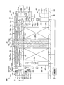
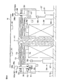
- FIG. 4 is a schematic diagram showing a vertical cross section of the spin chuck along the line II-II shown in FIG. 3. It is a schematic plan view of a spin chuck.
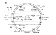
- FIG. 4 is a schematic diagram showing a horizontal cross section of the spin chuck along the line IV-IV shown in FIG. 2. It is a schematic diagram which shows the vertical cross section for demonstrating the chuck
- FIG. 10 is a schematic diagram illustrating a state in which SPM is supplied to the substrate in the example of the substrate processing illustrated in FIG. 9.
- FIG. 10 is a schematic diagram illustrating a state in which pure water is supplied to the substrate in the example of the substrate processing illustrated in FIG. 9.
- FIG. 10 is a schematic diagram illustrating a state in which SC1 is supplied to the substrate in the example of the substrate processing illustrated in FIG. 9.
- FIG. 10 is a schematic diagram illustrating a state in which SC1 is supplied to the substrate in the example of the substrate processing illustrated in FIG. 9.
- FIG. 10 is a schematic diagram illustrating a state in which IPA is supplied to the substrate in the example of the substrate processing illustrated in FIG. 9.
- FIG. 10 is a schematic diagram showing a state where IPA is removed from the substrate in an example of the processing of the substrate shown in FIG. 9.
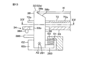
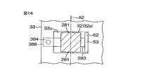
- FIG. 10 is a schematic diagram showing a state where the substrate is dried in an example of the processing of the substrate shown in FIG. 9. It is a schematic diagram which shows the vertical cross section containing the movable chuck which concerns on 2nd Embodiment of this invention.
- FIG. 12 is a schematic diagram showing a horizontal cross section along the line XII-XII shown in FIG. 11.
- FIG. 1 is a schematic view of the inside of a chamber 4 provided in the substrate processing apparatus 1 according to the first embodiment of the present invention viewed horizontally.
- the substrate processing apparatus 1 is a single-wafer type apparatus that processes a disk-shaped substrate W such as a semiconductor wafer one by one.
- the substrate processing apparatus 1 includes a processing unit 2 that processes a substrate W with a processing fluid such as a processing liquid or a processing gas, a transfer robot R1 (see FIG. 3) that transfers the substrate W to the processing unit 2, and a substrate processing apparatus 1.
- a control device 3 for controlling.
- the control device 3 is a computer that includes a memory that stores information such as a program and a processor that controls the substrate processing apparatus 1 in accordance with the information stored in the memory.
- the processing unit 2 includes a box-shaped chamber 4 having an internal space, and a spin chuck that rotates around a vertical rotation axis A1 that passes through a central portion of the substrate W while holding a single substrate W horizontally in the chamber 4. 31, a plurality of nozzles that discharge various fluids toward the substrate W held by the spin chuck 31, and a cylindrical cup 26 that surrounds the periphery of the spin chuck 31.
- the plurality of nozzles includes a first chemical liquid nozzle 5 and a second chemical liquid nozzle 9 that discharge the chemical liquid toward the upper surface of the substrate W.
- the first chemical liquid nozzle 5 is connected to a first chemical liquid pipe 6 in which a first chemical liquid valve 7 is interposed.
- the second chemical liquid nozzle 9 is connected to a second chemical liquid pipe 10 in which a second chemical liquid valve 11 is interposed.
- the first chemical liquid valve 7 is opened, the chemical liquid is supplied from the first chemical liquid pipe 6 to the first chemical liquid nozzle 5 and discharged from the first chemical liquid nozzle 5.
- the first chemical liquid valve 7 is closed, the discharge of the chemical liquid from the first chemical liquid nozzle 5 is stopped.
- a specific example of the chemical solution (first chemical solution) discharged from the first chemical solution nozzle 5 is SPM (mixed solution of sulfuric acid and hydrogen peroxide solution).
- a specific example of the chemical liquid (second chemical liquid) discharged from the second chemical liquid nozzle 9 is SC1 (mixed liquid of ammonia water, hydrogen peroxide water, and water).
- the first chemical solution may be phosphoric acid.
- the first chemical solution is sulfuric acid, nitric acid, hydrochloric acid, hydrofluoric acid, phosphoric acid, acetic acid, aqueous ammonia, aqueous hydrogen peroxide, organic acid (eg, citric acid, oxalic acid, etc.), organic alkali (eg, A liquid containing at least one of TMAH (tetramethylammonium hydroxide and the like), a surfactant, and a corrosion inhibitor may be used.
- organic acid eg, citric acid, oxalic acid, etc.
- organic alkali eg, A liquid containing at least one of TMAH (tetramethylammonium hydroxide and the like)
- surfactant etramethylammonium hydroxide and the like
- a corrosion inhibitor may be used.
- the first chemical liquid nozzle 5 is connected to a first nozzle moving mechanism 8 that moves the first chemical liquid nozzle 5.
- the second chemical liquid nozzle 9 is connected to a second nozzle moving mechanism 12 that moves the second chemical liquid nozzle 9.
- the first nozzle moving mechanism 8 includes a first chemical liquid nozzle between a processing position where the first chemical liquid lands on the upper surface of the substrate W and a standby position where the first chemical liquid nozzle 5 is positioned around the cup 26 in plan view. 5 is moved. Furthermore, the first nozzle moving mechanism 8 moves the first chemical liquid landing position within the upper surface of the substrate W by moving the first chemical liquid nozzle 5 horizontally. The same applies to the second nozzle moving mechanism 12.
- the plurality of nozzles includes a rinse liquid nozzle 13 that discharges the rinse liquid downward toward the center of the upper surface of the substrate W.
- the rinse liquid nozzle 13 is fixed with respect to the chamber 4.
- the rinse liquid nozzle 13 may be connected to a third nozzle moving mechanism that moves the rinse liquid nozzle 13.
- the rinse liquid nozzle 13 is connected to a first rinse liquid pipe 14 in which a first rinse liquid valve 15 is interposed.
- a specific example of the rinsing liquid discharged from the rinsing liquid nozzle 13 is pure water (deionized water).
- the rinse liquid may be a rinse liquid other than pure water such as carbonated water, electrolytic ion water, hydrogen water, ozone water, and hydrochloric acid water having a diluted concentration (eg, about 10 to 100 ppm).
- the plurality of nozzles includes a lower surface nozzle 16 that discharges the rinse liquid upward toward the center of the lower surface of the substrate W.
- the lower surface nozzle 16 is fixed to the chamber 4.
- the lower surface nozzle 16 is connected to a second rinse liquid pipe 17 in which a second rinse liquid valve 18 is interposed.
- a specific example of the rinsing liquid discharged from the lower surface nozzle 16 is pure water.
- the rinse liquid may be a rinse liquid other than the pure water described above.
- the liquid discharged from the lower surface nozzle 16 may be a processing liquid other than the rinsing liquid.
- the lower surface nozzle 16 includes a disc portion 16a that is horizontally held at a height between the upper surface of the spin base 33 and the lower surface of the substrate W, and a cylindrical portion that extends downward from the disc portion 16a along the rotation axis A1. 16b.
- the disc portion 16 a is an annular shape surrounding the rotation axis A ⁇ b> 1, and has an outer diameter smaller than the diameter of the substrate W.
- the outer diameter of the cylindrical part 16b is smaller than the outer diameter of the disc part 16a.
- the cylindrical portion 16 b is inserted into a through hole that opens at the center of the upper surface of the spin base 33.
- the discharge port of the lower surface nozzle 16 is opened at the center of the upper surface of the disk portion 16a.
- the discharge port of the lower surface nozzle 16 faces the center portion of the lower surface of the substrate W in the vertical direction.
- the plurality of nozzles includes a solvent nozzle 19 that discharges IPA (liquid) toward the upper surface of the substrate W, and a gas nozzle 22 that discharges gas toward the upper surface of the substrate W.
- the solvent nozzle 19 is connected to a solvent pipe 20 in which a solvent valve 21 is interposed.
- IPA isopropyl alcohol
- the gas nozzle 22 is connected to a gas pipe 23 in which a gas valve 24 is interposed.
- a specific example of the gas discharged from the gas nozzle 22 is nitrogen gas.
- the gas may be an inert gas other than nitrogen gas, or may be a gas other than the inert gas.
- the solvent nozzle 19 is connected to a fourth nozzle moving mechanism 25 that moves the solvent nozzle 19 between the processing position and the standby position.
- the gas nozzle 22 is also connected to the fourth nozzle moving mechanism 25.
- the gas nozzle 22 may be connected to a fifth nozzle moving mechanism different from the fourth nozzle moving mechanism 25.
- the fourth nozzle moving mechanism 25 moves the solvent nozzle 19 and the gas nozzle 22 up and down between a processing position where the solvent nozzle 19 and the gas nozzle 22 are close to the upper surface of the substrate W and a standby position above the processing position.
- the fourth nozzle moving mechanism 25 may be a mechanism that moves the solvent nozzle 19 and the gas nozzle 22 horizontally.
- the cup 26 includes a plurality of splash guards 28 for receiving the liquid discharged outward from the substrate W and a plurality of annular trays 27 for receiving the liquid guided downward by the splash guard 28.
- the plurality of splash guards 28 surround the spin chuck 31.
- the splash guard 28 includes a cylindrical inclined portion 28a extending obliquely upward toward the rotation axis A1 and a cylindrical guide portion 28b extending downward from a lower end portion (outer end portion) of the inclined portion 28a.
- the inclined portion 28 a includes an annular upper end having a larger inner diameter than the substrate W and the spin base 33.
- the upper end of the inclined portion 28 a corresponds to the upper end of the cup 26.
- the plurality of guide portions 28 b are respectively disposed above the plurality of annular trays 27.
- the upper end of the inclined portion 28a is located above the holding position where the plurality of chuck members 32 hold the substrate W, and the upper end of the inclined portion 28a is located below the holding position.
- the splash guard 28 is vertically moved between the lower position and the lower position.
- a liquid such as a chemical liquid or a rinse liquid
- the splash guard 28 is disposed at the upper position.
- the liquid splashed outward from the substrate W is received by the inclined portion 28a and then collected in the annular tray 27 by the guide portion 28b.
- the control device 3 controls the guard lifting / lowering unit so that one of the splash guards 28 selected according to the type of liquid supplied to the substrate W is opposed to the outer peripheral surface of the substrate W.
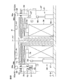
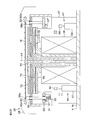
- FIG. 2 is a schematic diagram showing a vertical cross section of the spin chuck 31 along the line II-II shown in FIG.
- FIG. 3 is a schematic plan view of the spin chuck 31.
- FIG. 4 is a schematic diagram showing a horizontal cross section of the spin chuck 31 along the line IV-IV shown in FIG.
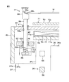
- FIG. 5 is a schematic diagram showing a vertical cross section for explaining the chuck opening / closing mechanism 34 provided in the spin chuck 31.
- the exposed portions of the drive magnet 56 and the drive magnet 68 are filled with black.
- FIG. 5 shows a state where the movable chuck 32a is located at the open position.
- the spin chuck 31 includes a disc-shaped spin base 33 that is horizontally held, a plurality of chuck members 32 that horizontally hold the substrate W above the spin base 33, and a plurality of chuck members.
- a chuck opening / closing mechanism 34 that opens and closes 32, and a spin motor 36 that rotates the substrate W held by the plurality of chuck members 32 by rotating the spin base 33 and the chuck member 32 about the rotation axis A1.
- the spin base 33 is, for example, a solid disk having an outer diameter larger than the diameter of the substrate W.
- the spin motor 36 is a servo motor including a rotor 36b and a stator 36a.
- the rotor 36 b is connected to the spin base 33 via a spin shaft 35 that extends downward from the spin base 33.
- the stator 36a surrounds the rotor 36b.
- the rotor 36b and the stator 36a are disposed in the chuck housing 37.
- the spin motor 36 and the chuck housing 37 are disposed below the spin base 33.
- the chuck housing 37 includes a cylindrical lower cylindrical portion 37a extending upward from the bottom portion 4a of the chamber 4, an annular portion 37b extending inwardly from an upper end portion of the lower cylindrical portion 37a, and an inner end of the annular portion 37b. And an upper cylindrical portion 37c extending upward from the top.
- the chuck member 32 protrudes upward from the upper surface of the spin base 33. As shown in FIG. 3, the plurality of chuck members 32 are arranged at intervals around the rotation axis A ⁇ b> 1.
- the plurality of chuck members 32 include a plurality of movable chucks 32 a that can move with respect to a lifting member 62 described later, and a plurality of fixed chucks 32 b that are fixed to the lifting member 62.
- the plurality of movable chucks 32a are arranged in the circumferential direction without sandwiching the fixed chuck 32b therebetween.
- the movable chuck 32a has a spin base around a vertical chuck rotation axis A2 between a closed position where the grip portion 38a is pressed against the outer peripheral portion of the substrate W and an open position where the grip portion 38a is separated from the outer peripheral portion of the substrate W. 33 and the elevating member 62 can be rotated.
- the movable chuck 32 a includes a chuck head 38 that contacts the substrate W and a base shaft 39 that extends downward from the chuck head 38.
- the chuck head 38 and the base shaft 39 may be separate members or an integral member.
- the chuck head 38 includes a support portion 38 b that supports the substrate W from below and a grip portion 38 a that is pressed against the outer peripheral portion of the substrate W.
- the gripping portion 38a includes two groove inner surfaces that form a receiving groove having a V-shaped cross section that opens inward.
- the support portion 38b includes an inclined surface that extends obliquely downward from the grip portion 38a toward the rotation axis A1.
- the support portion 38 b and the grip portion 38 a are disposed above the spin base 33.
- the grip portion 38a is disposed around the substrate W.
- the support portion 38b is disposed below the substrate W.
- the base shaft 39 has a cylindrical shape extending in the vertical direction.
- the base shaft 39 is inserted into a through portion 33p that penetrates the spin base 33 in the vertical direction. The liquid is prevented from entering the through portion 33p by the annular seal 41 surrounding the chuck member 32.
- the base shaft 39 is supported by the spin base 33 via a sliding bearing 42 disposed in the through portion 33p. Both the base shafts 39 of the movable chuck 32 a and the fixed chuck 32 b are movable in the vertical direction with respect to the spin base 33.
- the base shaft 39 of the fixed chuck 32 b is fixed to the elevating member 62.
- the base shaft 39 of the movable chuck 32a is rotatable around the chuck rotation axis A2 with respect to the elevating member 62.
- the base shaft 39 of the movable chuck 32a is inserted into a penetrating portion 62p that penetrates the elevating member 62 in the vertical direction.
- the base shaft 39 of the movable chuck 32 a protrudes downward from the elevating member 62.
- the base shaft 39 of the movable chuck 32a is supported by the elevating member 62 via a rolling bearing 44 disposed in the penetrating portion 62p.
- the movable chuck 32a is rotatable with respect to the elevating member 62 around the center line of the base shaft 39 corresponding to the chuck rotation axis A2.
- a force for moving the elevating member 62 in the vertical direction is transmitted to the movable chuck 32 a via the rolling bearing 44.
- the movable chuck 32a moves in the vertical direction together with the elevating member 62.
- the transfer robot R1 places the substrate W on the hand H1 on the support portion 38b of each chuck member 32 in a state where each movable chuck 32a is located at the open position.
- the chuck opening / closing mechanism 34 moves each movable chuck 32a toward the closed position in this state, the plurality of gripping portions 38a approach the outer peripheral portion of the substrate W while the substrate W is lifted by the plurality of support portions 38b.
- the support portions 38b of all the chuck members 32 are separated from the substrate W, and the grip portions 38a of all the chuck members 32 are pressed against the outer peripheral portion of the substrate W.
- the chuck opening / closing mechanism 34 includes an open mechanism that moves the plurality of movable chucks 32a toward the open position, and a close mechanism that moves the plurality of movable chucks 32a toward the closed position.
- the closing mechanism includes a plurality of coil springs 51 respectively wound around the plurality of movable chucks 32a.
- the open mechanism includes a plurality of driven magnets 55 respectively fixed to the plurality of movable chucks 32a, and a drive magnet 56 that moves the plurality of driven magnets 55 toward the open position by moving the plurality of driven magnets 55. .
- the coil spring 51 is wound around the base shaft 39 of the movable chuck 32a.
- the coil spring 51 is disposed below the elevating member 62.
- the coil spring 51 is accommodated in a casing 52 attached to the elevating member 62.
- One end of the coil spring 51 is inserted into the insertion hole of the holding portion 53 fixed to the elevating member 62.
- the other end of the coil spring 51 is inserted into a holding hole 54 that opens on the outer peripheral surface of the movable chuck 32a.
- the movement of the one end portion of the coil spring 51 relative to the elevating member 62 is restricted.
- the other end of the coil spring 51 is restricted from moving relative to the movable chuck 32a.
- FIG. 5 shows a state where the movable chuck 32a is located at the open position.
- the origin position, the open position, and the closed position are different positions with different rotation angles around the chuck rotation axis A2.
- the closed position is a position between the origin position and the open position with respect to the rotation direction of the movable chuck 32a.
- the plurality of driven magnets 55 are arranged in the plurality of casings 52, respectively.
- the drive magnet 56 is disposed in the chuck housing 37.
- the drive magnet 56 is separated from the driven magnet 55 by the casing 52 and the chuck housing 37.
- the drive magnet 56 is disposed inward of the driven magnet 55.
- the drive magnet 56 is disposed outside the spin motor 36.
- the drive magnet 56 may be disposed directly below the driven magnet 55.
- the drive magnet 56 is arranged along a circle surrounding the rotation axis A1.
- the drive magnet 56 is opposed to any driven magnet 55 in the radial direction in plan view.
- the drive magnet 56 is annular in plan view.
- the drive magnet 56 may be a ring that is continuous over the entire circumference, or may include a plurality of magnets arranged on a circumference that surrounds the rotation axis A1.
- the opening mechanism of the chuck opening / closing mechanism 34 is an opening / closing actuator that changes the distance between the driven magnet 55 and the driving magnet 56 by moving the driving magnet 56 in addition to the driving magnet 56 and the driven magnet 55. 57.
- the strength of the magnetic force acting between the driven magnet 55 and the drive magnet 56 is changed according to the interval between the driven magnet 55 and the drive magnet 56.
- the opening / closing actuator 57 is disposed in the chuck housing 37.
- the opening / closing actuator 57 moves the drive magnet 56 in the vertical direction between an upper position (position indicated by a two-dot chain line in FIG. 2) and a lower position (position indicated by a solid line in FIG. 2).
- the upper position is a position where the magnetic force (attraction or repulsive force) acting between the drive magnet 56 and the driven magnet 55 exceeds the restoring force of the coil spring 51, and the movable chuck 32a is disposed at the open position.
- the lower position is a position where the magnetic force acting between the drive magnet 56 and the driven magnet 55 is less than the restoring force of the coil spring 51, and the movable chuck 32a is disposed at the closed position.
- the opening / closing actuator 57 is an air cylinder.
- the opening / closing actuator 57 may include an electric motor, and a ball screw and a ball nut that convert rotation of the electric motor into movement of the drive magnet 56 in the vertical direction instead of the air cylinder.
- the opening / closing actuator 57 includes a rod extending in the axial direction of the air cylinder, a piston connected to the rod, and a cylindrical cylinder tube surrounding the rod and the piston.
- the drive magnet 56 is connected to the rod of the air cylinder. The drive magnet 56 moves up and down together with the rod of the air cylinder.
- the spin chuck 31 moves the chuck members 32 up and down with respect to the spin base 33, so that the substrate W held by the chuck members 32 and the heating member 72 described later are moved up and down.
- An interval changing mechanism 61 that changes the interval in the direction is included.
- the interval changing mechanism 61 includes a lifting member 62 that supports the plurality of chuck members 32, a plurality of guide members 64 that guide the lifting member 62 in the vertical direction, and a lifting drive that generates power for moving the lifting member 62 in the vertical direction.
- Unit 66 Unit 66.
- the elevating member 62 has an annular shape surrounding the rotation axis A1.
- the elevating member 62 surrounds the chuck housing 37.
- the elevating member 62 is disposed below the spin base 33.
- the elevating member 62 is surrounded by a cylindrical skirt 63 fixed to the spin base 33.
- the elevating member 62 is disposed above the annular portion 37b of the chunk housing.
- the plurality of chuck members 32 protrude upward from the upper surface of the elevating member 62. When the elevating member 62 moves in the vertical direction, all the chuck members 32 move in the vertical direction together with the elevating member 62.
- the guide member 64 includes a guide shaft 64a extending in the vertical direction and a guide stopper 64b larger than the guide shaft 64a in plan view.
- the guide shaft 64a is inserted into a through hole 65 that penetrates the elevating member 62 in the vertical direction.
- the guide stopper 64b is disposed below the elevating member 62.
- the guide stopper 64b is larger than the through hole 65 of the elevating member 62 in plan view.
- the guide shaft 64a extends downward from the spin base 33.
- the guide shaft 64 a is fixed to the spin base 33.
- the guide stopper 64b is fixed to the guide shaft 64a.
- the elevating member 62 is disposed between the spin base 33 and the guide stopper 64b.
- the elevating member 62 is movable in the vertical direction with respect to the spin base 33 between a lower position where the lower surface of the elevating member 62 is in contact with the guide stopper 64b and an upper position where the elevating member 62 is separated upward from the guide stopper 64b. It is.
- the elevating drive unit 66 is a magnetic force generating unit that elevates and lowers the elevating member 62 with a magnetic force, for example.
- the magnetic force generation unit includes a driven magnet 67 fixed to the elevating member 62, a drive magnet 68 that raises the elevating member 62 by raising the driven magnet 67, and a driven magnet 67 that moves the drive magnet 68 in the vertical direction. And a lift actuator 69 that changes the strength of the magnetic force acting between the drive magnet 68 and the drive magnet 68.
- the driven magnet 67 is fixed to the elevating member 62.
- the driven magnet 67 moves in the vertical direction together with the elevating member 62.
- the driven magnet 67 is disposed outside the chuck housing 37.
- the drive magnet 68 and the lift actuator 69 are disposed in the chuck housing 37.
- the drive magnet 68 is separated from the driven magnet 67 by the chuck housing 37.
- the drive magnet 68 is disposed outside the spin motor 36.
- the drive magnet 68 is disposed below the driven magnet 67.
- the drive magnet 68 faces the driven magnet 67 in the vertical direction via the chuck housing 37.
- the drive magnet 68 overlaps at least a part of the driven magnet 67 in plan view.
- the drive magnet 68 may not overlap the driven magnet 67 in plan view.
- the driven magnet 67 and the drive magnet 68 are both arranged along a circle surrounding the rotation axis A1.
- the driven magnet 67 has an arc shape in plan view.
- the drive magnet 68 is annular in plan view.
- the drive magnet 68 may be a ring that is continuous over the entire circumference, or may include a plurality of magnets arranged on a circumference that surrounds the rotation axis A1.
- the drive magnet 68 of the interval changing mechanism 61 and the drive magnet 56 of the chuck opening / closing mechanism 34 are disposed at different positions with different distances from the rotation axis A1.
- the elevating actuator 69 is an air cylinder.
- the lift actuator 69 may include an electric motor, and a ball screw and a ball nut that convert the rotation of the electric motor into the movement of the drive magnet 68 in the vertical direction instead of the air cylinder.
- the lift actuator 69 includes a rod extending in the axial direction of the air cylinder, a piston connected to the rod, and a cylindrical cylinder tube surrounding the rod and the piston.
- the drive magnet 68 is connected to the rod of the air cylinder.
- the drive magnet 68 moves in the vertical direction together with the rod of the air cylinder.
- the elevating actuator 69 moves the drive magnet 68 in the vertical direction between an upper position (position indicated by a two-dot chain line in FIG. 2) and a lower position (position indicated by a solid line in FIG. 2).
- the drive magnet 68 moves upward, the driven magnet 67 is lifted by a magnetic force (reaction force) acting between the driven magnet 67 and the drive magnet 68.
- the elevating member 62 rises.
- the elevating member 62 is disposed at the upper position.
- the guide stopper 64b of each guide member 64 contacts the elevating member 62, and the elevating member 62 is arranged at the lower position.
- All the chuck members 32 move between the upper position and the lower position as the elevating member 62 moves up and down.
- the heat generating member 72 described later is disposed below the substrate W supported by the support portions 38b of the plurality of chuck members 32.
- the upper position of the chuck member 32 is a retracted position where the substrate W and the heat generating member 72 are separated from each other.
- the lower position of the chuck member 32 is a close position where the substrate W and the heat generating member 72 are close to each other.
- the distance D1 (see FIG. 7) from the upper surface of the heat generating member 72 to the lower surface of the substrate W held by the plurality of chuck members 32 is It is smaller than the thickness T1 of the hand H1 of the transfer robot R1 that supports the substrate W from below.
- the distance D1 is, for example, 0.1 to 10 mm. Therefore, at this time, the transfer robot R1 cannot place the substrate W on the plurality of chuck members 32 or take the substrate W from the plurality of chuck members 32.
- FIG. 6A to 6B are schematic diagrams for explaining the delivery of the substrate W between the spin chuck 31 and the transfer robot R1.
- the transfer robot R1 places the substrate W on the plurality of chuck members 32, as shown in FIG. 6A, the lift actuator 69 positions the plurality of chuck members 32 in the upper position, and the open / close actuator 57 holds the movable chuck 32a. Position it in the open position.
- FIG. 6B in this state, the substrate W supported by the hand H1 is placed on the support portions 38b of the plurality of chuck members 32.
- the transfer robot R1 moves the hand H1 downward by a movement amount that does not allow the hand H1 to contact the heat generating member 72. As a result, the hand H1 is separated from the substrate W. Subsequently, the transfer robot R1 retracts the hand H1 from between the substrate W and the heating member 72.
- the opening / closing actuator 57 moves the movable chuck 32a toward the origin position after the hand H1 of the transfer robot R1 is retracted from below the substrate W. At this time, the movable chuck 32a does not reach the origin position and stops at the closed position that is a position before the origin position. As a result, the grip portion 38 a of the movable chuck 32 a is pressed against the outer peripheral portion of the substrate W by the restoring force of the coil spring 51. Along with this, the holding portion 38a of the fixed chuck 32b is also pressed against the outer peripheral portion of the substrate W. Thereby, the substrate W is held by the plurality of chuck members 32.
- the lifting actuator 69 moves the plurality of chuck members 32 to the upper position. Thereafter, the opening / closing actuator 57 moves the movable chuck 32a to the open position. 6B, the grip portions 38a of all the chuck members 32 are separated from the outer peripheral portion of the substrate W, and the support portions 38b of all the chuck members 32 are in contact with the outer peripheral portion of the substrate W.
- the transfer robot R1 inserts the hand H1 between the substrate W and the heat generating member 72, and moves the hand H1 upward. As shown in FIG. 6A, in this process, the substrate W is separated from the support portions 38b of all the chuck members 32 and is supported by the hand H1 of the transport robot R1.
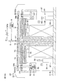
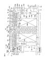
- FIG. 7 is a schematic diagram showing a vertical cross section for explaining the IH heating mechanism 71 provided in the spin chuck 31.
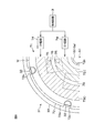
- FIG. 8 is a schematic plan view for explaining the arrangement of the heating coil 73.
- the spin chuck 31 includes an IH heating mechanism 71 that heats the substrate W held by the plurality of chuck members 32.
- the IH heating mechanism 71 generates the alternating magnetic field applied to the heat generating member 72 by supplying power to the heat generating member 72 that heats the substrate W, the heating coil 73 to which power is supplied, and the heating coil 73.
- an IH circuit 74 that generates heat.
- the IH heating mechanism 71 further includes a magnetic shielding member 77 that protects members other than the heat generating member 72 from an alternating magnetic field, and a support member 78 that supports the heating coil 73.
- the heat generating member 72 is a conductor that generates Joule heat as eddy currents are generated due to an alternating magnetic field.
- the heat generating member 72 is also called a susceptor.
- At least the surface of the heat generating member 72 is formed of a material having chemical resistance.
- at least the surface of the spin base 33 is formed of a material having chemical resistance. That is, all the parts that come into contact with the chemical solution are formed of a material having chemical resistance.
- members other than the heating member 72 such as the chuck member 32 and the spin base 33.
- the heat generating member 72 may be a plurality of integrated members or a single integrated member.
- the heat generating member 72 may include a carbon core material and a silicon carbide (SiC) coating layer covering the surface of the core material, or may be formed of glassy carbon. Good.
- the heat generating member 72 may be formed of a material other than these, such as a metal.
- at least a part of the heat generating member 72 may be formed of a soft magnetic material such as iron that blocks the magnetic field.
- the heat generating member 72 includes a plate-like portion 72 a disposed between the substrate W and the spin base 33.
- the plate-like portion 72a is, for example, an annular shape surrounding the rotation axis A1.
- the thickness (vertical length) of the plate-like portion 72a is smaller than the thickness T3 of the spin base 33.
- the upper and lower surfaces of the plate-like portion 72a are parallel to the upper and lower surfaces of the substrate W.
- the lower surface of the plate-like portion 72a faces the upper surface of the spin base 33 in parallel through the space.
- the distance from the upper surface of the spin base 33 to the lower surface of the plate-like portion 72a may be equal to the distance D1 from the upper surface of the plate-like portion 72a to the lower surface of the substrate W, or may be longer or shorter than the distance D1. .
- the transfer robot R1 places the substrate W on the plurality of chuck members 32 or takes the substrate W from the plurality of chuck members 32. Can do.
- the heat generating member 72 includes a plurality of leg portions 72b extending downward from the plate-like portion 72a.
- the leg portion 72b may be a part of the spin base 33.
- the spin base 33 may include a disc portion having an outer diameter larger than the diameter of the substrate W and a plurality of leg portions 72b extending upward from the horizontal upper surface of the disc portion.
- the leg portion 72 b extends from the lower surface of the plate-like portion 72 a to the upper surface of the spin base 33.
- the plate-like portion 72a is supported by a plurality of leg portions 72b.
- the heat generating member 72 is fixed to the spin base 33.
- the heat generating member 72 rotates around the rotation axis A ⁇ b> 1 together with the spin base 33.
- the plurality of chuck members 32 are inserted into the plurality of through portions 72 p of the heat generating member 72, respectively.
- the penetration part 72p penetrates the outer peripheral part of the heat generating member 72 in the vertical direction.
- the through portion 72p may be a notch that opens on the outer peripheral surface of the plate-like portion 72a, or may be a through hole that is closed on the entire periphery.
- the outer peripheral surface of the plate-like portion 72 a is located outward from the inner end of the chuck member 32.
- the outer diameter of the plate-like portion 72 a that is, the outer diameter of the heat generating member 72 is smaller than the outer diameter of the spin base 33 and larger than the outer diameter of the substrate W.
- the outer diameter of the heat generating member 72 may be equal to the outer diameter of the substrate W or may be smaller than the outer diameter of the substrate W.
- the heating coil 73 is disposed between the support member 78 and the spin base 33.
- the heating coil 73 is spaced downward from the lower surface of the spin base 33.
- the heating coil 73 is disposed so as to overlap the heat generating member 72 in plan view.
- the heating coil 73 is separated from the heat generating member 72 and is not physically connected to the heat generating member 72.
- the heating coil 73 surrounds the spin shaft 35 with an interval in the radial direction.
- the plurality of chuck members 32 are arranged around the heating coil 73.
- the heating coil 73 is separated from the chuck member 32 in the radial direction.
- the outer end of the heating coil 73 is disposed outward from the outer peripheral surface of the spin motor 36.
- the heating coil 73 is arranged in an annular region surrounding the rotation axis A1.
- FIG. 8 shows an example in which two heating coils 73 that are independent of each other are arranged in two annular regions, respectively.
- the two heating coils 73 include an inner coil 73I disposed in the inner annular region RI surrounding the rotation axis A1 and an outer coil 73O disposed in the outer annular region RO concentrically surrounding the inner annular region RI.
- the two heating coils 73 are connected to the two IH circuits 74, respectively.
- the frequency of the alternating current flowing through the two heating coils 73 is individually changed by the two IH circuits 74.
- the heating member 72 is disposed in an alternating magnetic field generated in the vicinity of the heating coil 73.
- the frequency of the alternating current flowing through the heating coil 73 is changed by the IH circuit 74.
- the temperature of the heat generating member 72 is changed by the frequency of the alternating current flowing through the heating coil 73.
- the IH circuit 74 is controlled by the control device 3. Since the two heating coils 73 that are independent from each other are provided, the control device 3 can also heat the heat generating member 72 so that the temperature of the heat generating member 72 is uniform, and the radial temperature gradient is a heat generating member.
- the heat generating member 72 can also generate heat so as to be generated at 72.
- thermometer 75 The temperature of the heating member 72 is detected by a thermometer 75.
- FIG. 8 shows an example in which two thermometers 75 for detecting the temperature of the heat generating member 72 are provided at two positions at different distances from the rotation axis A1.
- the number of thermometers 75 may be one, or may be three or more.
- the detection value of the thermometer 75 is input to the control device 3.
- the control device 3 controls the IH circuit 74 based on the detection value of the thermometer 75, thereby bringing the temperature of the heat generating member 72 close to the target temperature. Thereby, the heat generating member 72 is maintained at the target temperature with high accuracy.
- thermometer 75 is disposed below the heating coil 73.
- the thermometer 75 is opposed to the spin base 33 through a gap between the heating coils 73.
- the thermometer 75 is a radiation thermometer that detects the temperature of an object by detecting the intensity of infrared light or visible light emitted from the object.
- the thermometer 75 is a non-contact thermometer that detects the temperature of the heat generating member 72 without contacting the heat generating member 72.
- the thermometer 75 detects the temperature of the heat generating member 72 through the plurality of detection windows of the spin base 33 closed with the plurality of transparent members 76.
- the detection window penetrates the spin base 33 in the vertical direction.
- the transparent member 76 is formed of a transparent material that transmits light including infrared rays.
- thermometer 75 is supported by the support member 78. Even if the heat generating member 72 rotates together with the spin base 33, the thermometer 75 does not rotate.
- the plurality of detection windows provided on the spin base 33 also rotate. As shown in FIG. 8, the plurality of detection windows of the spin base 33 are arranged in the circumferential direction on the circumference surrounding the rotation axis A1. Accordingly, during almost all the period in which the spin base 33 is rotating, one of the plurality of detection windows faces the thermometer 75. Therefore, the thermometer 75 can detect the temperature of the heat generating member 72 even when the spin base 33 is rotating.
- the magnetic shielding member 77 includes a cylindrical outer wall portion 77 a that surrounds the heating coil 73, and a lower wall portion 77 b that is positioned below the heating coil 73.
- the magnetic shielding member 77 is made of a soft magnetic material such as iron.
- the lower wall portion 77b is located between the heating coil 73 and the support member 78 in the vertical direction.
- the lower wall portion 77b has an annular shape that surrounds the rotation axis A1.
- the outer wall portion 77a extends upward from the outer peripheral portion of the lower wall portion 77b.
- the outer wall portion 77a is located between the heating coil 73 and the chuck member 32 in the radial direction. Members located near the heating coil 73 such as the chuck member 32 are blocked from the alternating magnetic field by the magnetic blocking member 77.
- FIG. 7 shows an example in which the support member 78 is supported by the stator 36 a of the spin motor 36.
- the support member 78 is disposed above the spin motor 36.
- the support member 78 has an annular shape surrounding the rotation axis A1.
- the outer diameter of the support member 78 is larger than the outer diameter of the spin motor 36.
- the outer peripheral portion of the support member 78 is located above the upper cylindrical portion 37 c of the chuck housing 37.
- the spin shaft 35 is inserted into a through hole that penetrates the central portion of the support member 78 in the vertical direction.
- the support member 78 surrounds the spin shaft 35 with a gap in the radial direction.
- the control device 3 starts supplying power to the heating coil 73, an alternating magnetic field is generated in the vicinity of the heating coil 73, and the heat generating member 72 generates heat. Along with this, the temperature of the heat generating member 72 rises rapidly and is maintained at or near the target temperature of the heat generating member 72. As a result, the temperature of the substrate W rises rapidly and is maintained at or near the target temperature of the substrate W.
- the rotation of the spin motor 36 is transmitted to the heat generating member 72 via the spin shaft 35 and the spin base 33. Therefore, if the spin motor 36 rotates while the control device 3 is generating heat from the heat generating member 72, the heat generating member 72 rotates with the substrate W while heating the substrate W.
- the thickness T1 of the plate-like portion 72a of the heat generating member 72 is smaller than the thickness T3 of the spin base 33.
- the heat generating member 72 is thin, the volume of the heat generating member 72 can be reduced, and the heat capacity of the heat generating member 72 can be reduced. Thereby, the heat generating member 72 can be made to reach target temperature immediately.
- the time until the heat generating member 72 reaches the target temperature can be further shortened. In addition, uneven temperature of the heat generating member 72 can be reduced.
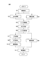
- FIG. 9 is a process diagram for explaining an example of the processing of the substrate W performed by the substrate processing apparatus 1.
- 10A to 10F are schematic views showing the state of the substrate W when each step included in the example of the processing of the substrate W shown in FIG. 9 is executed.
- the following steps are executed by the control device 3 controlling the substrate processing apparatus 1.
- the control device 3 is programmed to execute the following steps.
- a loading process for loading the substrate W into the chamber 4 is performed (step S1 in FIG. 9). Specifically, before the substrate W is carried into the chamber 4, all the splash guards 28 are disposed at the lower position, and all the movable nozzles including the first chemical liquid nozzle 5 are disposed at the standby position. Further, all the chuck members 32 are arranged at the upper position, and all the movable chucks 32a are arranged at the open position. In this state, the transfer robot R1 moves the hand H1 into the chamber 4 and places the substrate W on the hand H1 on the plurality of chuck members 32. As a result, the substrate W is carried into the chamber 4 and supported by the support portions 38b of the plurality of chuck members 32.
- the transfer robot R1 retracts the hand H1 from the inside of the chamber 4.
- the open / close actuator 57 moves all the movable chucks 32a to the closed position.
- the substrate W is separated from the support portions 38b of the plurality of chuck members 32 and is gripped by the grip portions 38a of the plurality of chuck members 32.
- the lifting actuator 69 moves all the chuck members 32 to the lower position.
- the spin motor 36 starts to rotate.
- the rotation of the spin motor 36 is transmitted to the substrate W through the spin base 33 and the chuck member 32.
- the substrate W rotates around the rotation axis A1.
- the first chemical solution supply step (step S2 in FIG. 9) for supplying SPM, which is an example of a chemical solution, to the upper surface of the substrate W, and the substrate W and the SPM on the substrate W are heated.
- the first heating step (step S3 in FIG. 9) is performed in parallel.
- the first nozzle moving mechanism 8 moves the first chemical solution nozzle 5 from the standby position to the processing position, and the guard lifting unit opposes one of the splash guards 28 to the outer peripheral portion of the substrate W. Let Then, the 1st chemical
- the first chemical nozzle 5 discharges SPM having a temperature higher than room temperature (for example, 140 ° C.) toward the upper surface of the rotating substrate W.
- the first nozzle moving mechanism 8 moves the first chemical solution nozzle 5 to move the SPM liquid deposition position with respect to the upper surface of the substrate W between the central portion and the outer peripheral portion.
- the first chemical liquid valve 7 is opened, the first chemical liquid valve 7 is closed and the SPM discharge is stopped. Thereafter, the first nozzle moving mechanism 8 retracts the first chemical solution nozzle 5 to the standby position.
- the SPM discharged from the first chemical solution nozzle 5 lands on the upper surface of the substrate W and then flows outward along the upper surface of the substrate W by centrifugal force. Therefore, SPM is supplied to the entire upper surface of the substrate W, and a liquid film of SPM that covers the entire upper surface of the substrate W is formed on the substrate W. Thereby, foreign substances such as a resist film are removed from the substrate W by SPM. Further, the first nozzle moving mechanism 8 moves the SPM landing position with respect to the upper surface of the substrate W between the central portion and the outer peripheral portion while the substrate W is rotating. The entire upper surface of the substrate W is scanned and the entire upper surface of the substrate W is scanned. Therefore, SPM is directly sprayed over the entire upper surface of the substrate W, and the entire upper surface of the substrate W is processed uniformly.
- the control device 3 starts supplying power to the heating coil 73.
- the start of power supply may be simultaneous with the opening of the first chemical valve 7 or the first chemical valve 7 It may be before or after the is opened.
- an alternating magnetic field is generated in the vicinity of the heating coil 73, and the heat generating member 72 generates heat.
- power supply to the heating coil 73 is stopped.
- the stop of the power supply may be simultaneously with the closing of the first chemical liquid valve 7 or may be before or after the first chemical liquid valve 7 is closed.
- the heating member 72 When the power supply to the heating coil 73 is started, the heating member 72 immediately reaches a predetermined high temperature.
- the heat generating member 72 is maintained at a high temperature higher than the boiling point of the first chemical liquid (SPM), for example.
- SPM first chemical liquid
- the heating robot 72 is so close to the lower surface of the substrate W that the hand H1 of the transfer robot R1 cannot enter between the substrate W and the heating member 72.
- the entire region or almost the entire region of the substrate W overlaps the heat generating member 72 in plan view. Therefore, the substrate W and the SPM on the substrate W are uniformly heated, and the processing capability of the SPM is increased. Thereby, the substrate W is efficiently processed by the SPM.
- a first rinsing liquid supply step for supplying pure water, which is an example of a rinsing liquid, to both the upper and lower surfaces of the substrate W is performed (step S4 in FIG. 9).
- the first rinsing liquid valve 15 is opened, and the rinsing liquid nozzle 13 starts discharging pure water.
- pure water is discharged from the rinse liquid nozzle 13 toward the center of the upper surface of the rotating substrate W.
- the pure water that has landed on the upper surface of the substrate W flows outward along the upper surface of the substrate W.
- the SPM on the substrate W is washed away with pure water discharged from the rinse liquid nozzle 13.
- a pure water liquid film covering the entire upper surface of the substrate W is formed.
- the second rinse liquid valve 18 is opened, and the lower surface nozzle 16 starts discharging pure water. Thereby, pure water is discharged from the lower surface nozzle 16 toward the center of the lower surface of the rotating substrate W.
- the second rinse liquid valve 18 may be opened simultaneously with the first rinse liquid valve 15, or may be opened before or after the first rinse liquid valve 15 is opened.
- the pure water that has landed on the lower surface of the substrate W flows outward along the lower surface of the substrate W.
- the SPM mist or the like adhering to the lower surface of the substrate W is washed away by pure water discharged from the lower surface nozzle 16.
- the second rinse liquid valve 18 is closed and the discharge of pure water is stopped.
- a second chemical liquid supply process is performed to supply SC1 as an example of the chemical liquid to the upper surface of the substrate W (step S5 in FIG. 9).
- the second nozzle moving mechanism 12 moves the second chemical liquid nozzle 9 from the standby position to the processing position, and the guard elevating unit moves the splash guard 28 different from that in the first chemical liquid supply process to the substrate W. Opposite the outer periphery.
- the second chemical liquid valve 11 is opened, and the second chemical liquid nozzle 9 starts to discharge SC1.
- the second nozzle moving mechanism 12 moves the second chemical solution nozzle 9 to move the liquid deposition position of the SC1 with respect to the upper surface of the substrate W between the central portion and the outer peripheral portion.
- the second chemical liquid valve 11 is closed and the discharge of SC1 is stopped.
- the second nozzle moving mechanism 12 retracts the second chemical liquid nozzle 9 to the standby position.
- SC1 discharged from the second chemical liquid nozzle 9 lands on the upper surface of the substrate W, and then flows outward along the upper surface of the substrate W by centrifugal force. Therefore, SC1 is supplied to the entire upper surface of the substrate W, and a liquid film of SC1 covering the entire upper surface of the substrate W is formed on the substrate W. Thereby, foreign substances such as particles are removed from the substrate W by the SC1. Further, since the second nozzle moving mechanism 12 moves the SC1 liquid landing position relative to the upper surface of the substrate W between the central portion and the outer peripheral portion while the substrate W is rotating, the SC1 liquid landing position is The entire upper surface of the substrate W is scanned and the entire upper surface of the substrate W is scanned. Therefore, SC1 is sprayed directly over the entire upper surface of the substrate W, and the entire upper surface of the substrate W is processed uniformly.
- a second rinsing liquid supply step for supplying pure water, which is an example of a rinsing liquid, to both the upper and lower surfaces of the substrate W is performed (step S6 in FIG. 9).
- the first rinsing liquid valve 15 is opened, and the rinsing liquid nozzle 13 starts discharging pure water.
- pure water is discharged from the rinse liquid nozzle 13 toward the center of the upper surface of the rotating substrate W.
- the pure water that has landed on the upper surface of the substrate W flows outward along the upper surface of the substrate W.
- the SC1 on the substrate W is washed away with pure water discharged from the rinse liquid nozzle 13. As a result, a pure water liquid film covering the entire upper surface of the substrate W is formed.
- the first rinse liquid valve 15 is closed and the discharge of pure water is stopped.
- the second rinse liquid valve 18 is opened, and the lower surface nozzle 16 starts discharging pure water. Thereby, pure water is discharged from the lower surface nozzle 16 toward the center of the lower surface of the rotating substrate W.
- the second rinse liquid valve 18 may be opened simultaneously with the first rinse liquid valve 15, or may be opened before or after the first rinse liquid valve 15 is opened.
- the pure water that has landed on the lower surface of the substrate W flows outward along the lower surface of the substrate W.
- the SC1 mist and the like adhering to the lower surface of the substrate W are washed away by pure water discharged from the lower surface nozzle 16.
- the second rinse liquid valve 18 is closed and the discharge of pure water is stopped.
- a solvent supply step for supplying IPA (liquid), which is an example of an organic solvent, to the substrate W, and the IPA and the substrate W on the substrate W are heated.
- the second heating step (step S8 in FIG. 9) is performed in parallel.
- the fourth nozzle moving mechanism 25 moves the solvent nozzle 19 from the standby position to the processing position, and the guard lifting / lowering unit forms a splash guard 28 different from that in the first and second chemical liquid supply processes. It is made to oppose the outer peripheral part of W. Thereafter, the solvent valve 21 is opened, and the solvent nozzle 19 starts discharging IPA.
- IPA is discharged from the solvent nozzle 19 toward the center of the upper surface of the rotating substrate W.
- the IPA that has landed on the upper surface of the substrate W flows outward along the upper surface of the substrate W.
- the pure water liquid film on the substrate W is replaced with an IPA liquid film covering the entire upper surface of the substrate W.
- the control device 3 starts supplying power to the heating coil 73. If the substrate W and the IPA on the substrate W are heated by the heat generating member 72, the power supply may be started at the same time as the solvent valve 21 is opened, or before the solvent valve 21 is opened. Or it may be after.
- the heating coil 73 When power supply to the heating coil 73 is started, an alternating magnetic field is generated in the vicinity of the heating coil 73, and the heat generating member 72 generates heat. Thereby, the heating of the substrate W is started. Then, when a predetermined time has elapsed from the start of power supply, power supply to the heating coil 73 is stopped. The power supply to the heating coil 73 is continued until, for example, the substrate W is dried in a drying process described later.
- the heating member 72 When the power supply to the heating coil 73 is started, the heating member 72 immediately reaches a predetermined high temperature. Each part of the heat generating member 72 is maintained at a temperature equal to or higher than the boiling point of IPA. The temperature of the substrate W reaches a value equal to or higher than the boiling point of the IPA in a state where the entire upper surface of the substrate W is covered with the IPA liquid film. As a result, the IPA evaporates at the interface between the IPA and the upper surface of the substrate W, and a gas layer is formed between the IPA liquid film and the upper surface of the substrate W.
- the IPA liquid film floats from the upper surface of the substrate W, the frictional resistance acting on the IPA liquid film on the substrate W is so small that it can be regarded as zero. Therefore, the IPA liquid film is easily slipped along the upper surface of the substrate W.
- the liquid film of IPA is removed from the substrate W in an IPA removal process described below.
- an IPA removal process for removing IPA from the substrate W is performed (step S9 in FIG. 9).
- the gas nozzle 22 is already arranged at the processing position in the solvent supply process.
- the gas valve 24 is opened, and the gas nozzle 22 starts to discharge nitrogen gas.
- the gas nozzle 22 discharges nitrogen gas toward the upper surface of the substrate W covered with the IPA liquid film.
- the spin motor 36 accelerates the substrate W in the rotation direction, and rotates the substrate W at a higher removal rotation speed than in the IPA supply process. If the substrate W rotates at the removal rotation speed when the gas nozzle 22 is discharging nitrogen gas, the substrate W may be accelerated at the same time as the gas valve 24 is opened. It may be before or after the valve 24 is opened. The discharge of nitrogen gas is continued until the substrate W is dried in a drying process described later.
- the gas nozzle 22 discharges nitrogen gas toward the spray position in the upper surface of the substrate W in a state where a gas layer is formed between the liquid film of IPA and the upper surface of the substrate W.
- the IPA in the blowing position is pushed away around it by the supply of nitrogen gas. Thereby, a dry area
- the liquid film of IPA on the substrate W is excluded from the substrate W as a lump without being divided into a large number of droplets. Therefore, the liquid film of IPA that floats from the substrate W can be quickly removed from the substrate W in a short time.
- a drying process is performed to dry the substrate W by shaking off the liquid adhering to the substrate W by centrifugal force (step S10 in FIG. 9).
- the spin motor 36 accelerates the substrate W in the rotation direction, and rotates the substrate W at a high rotation speed (for example, several thousand rpm) larger than the removal rotation speed.
- a large centrifugal force is applied to the liquid adhering to the substrate W, and the liquid is shaken off from the substrate W to the periphery thereof.
- the heat generating member 72 continues to generate heat, evaporation of the liquid on the substrate W is promoted.
- the gas nozzle 22 continues to discharge nitrogen gas, evaporation of the liquid on the substrate W is promoted. Thereby, the substrate W is dried in a short time.
- the spin motor 36 stops rotating. Further, power supply to the heating coil 73 is stopped, and the gas valve 24 is closed.
- step S11 in FIG. 9 an unloading process for unloading the substrate W from the chamber 4 is performed (step S11 in FIG. 9). Specifically, all the splash guards 28 are arranged at the lower position, and all the movable nozzles including the first chemical liquid nozzle 5 are arranged at the standby position. Further, all the chuck members 32 are arranged at the upper position, and all the movable chucks 32a are arranged at the open position. When the movable chuck 32a moves to the open position, the substrate W is separated from the gripping portion 38a of the chuck member 32 and supported by the support portion 38b of the chuck member 32. In this state, the transport robot R1 moves the hand H1 between the substrate W and the heat generating member 72 and raises the hand H1.
- the substrate W is separated from the support portions 38b of all the chuck members 32 and is supported by the hand H1 of the transport robot R1. Thereafter, the transport robot R1 retracts the hand H1 from the chamber 4 while supporting the substrate W with the hand H1. As a result, the substrate W is unloaded from the chamber 4.
- the substrate W is held by the plurality of chuck members 32.
- the power of the spin motor 36 is transmitted to the plurality of chuck members 32 via the spin base 33 located below the substrate W.
- the substrate W rotates around the rotation axis A1.
- the IH circuit 74 of the IH heating mechanism 71 supplies power to the heating coil 73 when the substrate W is rotating. Thereby, an alternating magnetic field applied to the heat generating member 72 is generated, and the heat generating member 72 generates heat.
- a processing fluid for processing the substrate W is supplied to the rotating substrate W. Thereby, the substrate W can be processed uniformly.
- the heat generating member 72 Since the heat generating member 72 is heated by induction heating, it is not necessary to connect a wiring or a connector for supplying power to the heat generating member 72 to the heat generating member 72. Therefore, the rotational speed of the substrate W is not limited by such a structure. Further, the heat generating member 72 that heats the substrate W is disposed not between the spin base 33 but between the substrate W and the spin base 33. Therefore, compared with the case where the heat generating member 72 is disposed inside the spin base 33, the interval between the substrate W and the heat generating member 72 can be shortened, and the heating efficiency of the substrate W can be increased.
- the heating coil 73 is disposed near the spin base 33. That is, as shown in FIG. 7, the vertical distance D ⁇ b> 2 between the heating coil 73 and the spin base 33 is narrower than the thickness T ⁇ b> 2 of the heating coil 73.
- the heating coil 73 is disposed below the spin base 33, and the heat generating member 72 is disposed above the spin base 33.
- the distance from the heating coil 73 to the heating member 72 is shortened. Thereby, since the alternating magnetic field applied to the heat generating member 72 becomes strong, the electric power supplied to the heating coil 73 can be efficiently converted into the heat of the heat generating member 72.
- the thickness T3 of the spin base 33 is reduced. That is, the thickness T3 of the spin base 33 is smaller than the thickness T2 of the heating coil 73.
- the spin base 33 is thick, not only the distance from the heating coil 73 to the heat generating member 72 is increased, but the alternating magnetic field applied to the heat generating member 72 is weakened. Therefore, by reducing the thickness T3 of the spin base 33, the temperature of the heat generating member 72 can be increased efficiently.
- the interval changing mechanism 61 relatively moves the plurality of chuck members 32 and the heat generating members 72 in the vertical direction. As a result, the vertical distance between the substrate W held by the plurality of chuck members 32 and the heat generating member 72 is changed. Therefore, the distance from the heating member 72 to the substrate W can be changed as necessary.
- the transport robot R1 places the substrate W supported on the hand H1 on the plurality of chuck members 32 in the retracted state in which the plurality of chuck members 32 are positioned at the upper positions as the retracted positions. .
- the transfer robot R1 lowers the hand H1 and separates it from the substrate W.
- the transfer robot R1 retracts the hand H1 from between the substrate W and the heating member 72.
- the transfer robot R1 raises the hand H1.
- the substrate W is separated from the plurality of chuck members 32 and supported by the hand H1.
- the heat generating member 72 is disposed near the substrate W.
- the hand H1 cannot enter between the substrate W and the heating member 72, and the substrate W is placed on the plurality of chuck members 32 or the plurality of chuck members 32. Can not be taken from.
- the delivery of the substrate W is performed in the retracted state.
- the heating of the substrate W is performed in the proximity state in which the plurality of chuck members 32 are positioned at the lower positions as the proximity positions. Therefore, the substrate W can be delivered without reducing the heating efficiency of the substrate W.
- the plurality of chuck members 32 include a movable chuck 32a that is movable with respect to the spin base 33 between a closed position and an open position.
- the vertical distance between the substrate W and the heat generating member 72 is changed by moving the plurality of chuck members 32 in the vertical direction with respect to the spin base 33.
- the movable chuck 32 a is not only movable between the closed position and the open position with respect to the spin base 33, but is also movable in the vertical direction with respect to the spin base 33.
- the structure for supporting the heat generating member 72 can be simplified.
- the outer wall 77 a of the magnetic shielding member 77 that absorbs magnetism surrounds the heating coil 73. Further, the lower wall portion 77 b of the magnetic shielding member 77 that absorbs magnetism is located below the heating coil 73. Therefore, it is possible to suppress or eliminate the influence of the alternating magnetic field on the members positioned around the heating coil 73. Similarly, the influence of the alternating magnetic field on the member located below the heating coil 73 can be suppressed or eliminated.
- the detection value of the thermometer 75 that detects the temperature of the heat generating member 72 is input to the control device 3.
- the control device 3 controls the power supplied to the heating coil 73 based on this detection value.
- the temperature of the heat generating member 72 can be brought close to the target temperature with high accuracy.
- the lower surface nozzle 16 discharges the processing fluid toward the lower surface of the substrate W.
- the lower surface nozzle 16 is arrange
- the movable chuck 32a rotates around the vertical chuck rotation axis A2.
- the volume of the passage space through which the movable chuck 32a passes can be easily reduced as compared with the case where the chuck rotation axis A2 is a horizontal straight line.
- the volume of the passage space can coincide with or substantially coincide with the volume of the movable chuck 32a.
- a second embodiment of the present invention will be described.
- the main difference between the first embodiment and the second embodiment is that, instead of the driven magnet 55 and the drive magnet 56, a pusher 284 that pushes the movable chuck 32a toward the open position is provided in the chuck opening / closing mechanism 34. It is.
- FIG. 11 is a schematic diagram showing a vertical cross section including the movable chuck 32a according to the second embodiment of the present invention.
- FIG. 12 is a schematic diagram showing a horizontal section along the line XII-XII shown in FIG. 11 to 12, the same components as those shown in FIGS. 1 to 10F are denoted by the same reference numerals as those in FIG. 1 and the description thereof is omitted.
- FIG. 11 shows a state in which the movable chuck 32a is disposed at the closed position and the upper position.
- the movable chuck 32a is supported by the elevating member 62 through a support shaft 281 extending horizontally and a support hole 282 into which the support shaft 281 is inserted.
- the support shaft 281 is provided in the movable chuck 32 a, and the support hole 282 is provided in the elevating member 62.
- the support shaft 281 may be provided in the elevating member 62, and the support hole 282 may be provided in the movable chuck 32a.
- the pair of support shafts 281 extend from the movable chuck 32a in directions opposite to each other.
- the pair of support shafts 281 are located on the same straight line.
- the support shaft 281 extends horizontally in the tangential direction of a circle surrounding the rotation axis A1 (see FIG. 2).
- the support hole 282 is recessed from the inner surface of the through portion 62p provided in the elevating member 62.
- the pair of support shafts 281 are respectively inserted into the pair of support holes 282.
- the movable chuck 32a is movable with respect to the elevating member 62 around a horizontal chuck rotation axis A2 corresponding to the center line of the support shaft 281.
- the upper end of the movable chuck 32a moves in the radial direction as the movable chuck 32a rotates around the chuck rotation axis A2.
- the penetrating portion 62 p of the elevating member 62 is a notch extending inward from the outer peripheral surface of the elevating member 62.
- the through portion 33 p of the spin base 33 is a notch extending inward from the outer peripheral surface of the spin base 33.
- the through-hole 62p and the through-hole 33p may be through-holes whose entire circumference is closed.
- the movable chuck 32 a includes an inward projecting portion 283 that extends inward from the base shaft 39.
- the coil spring 51 of the chuck opening / closing mechanism 34 is disposed above the inward protruding portion 283.
- One end portion of the coil spring 51 is held by a holding portion 53 fixed to the elevating member 62.
- the other end of the coil spring 51 is held by the inward protrusion 283.
- the coil spring 51 holds the movable chuck 32a at the origin position.
- the chuck opening / closing mechanism 34 includes a plurality of pushers 284 that push the plurality of movable chucks 32a toward the open position.
- the pusher 284 is disposed below the inward projecting portion 283.
- the pusher 284 is inserted into a through hole that penetrates the chuck housing 37.
- a gap between the outer peripheral surface of the pusher 284 and the inner peripheral surface of the through hole is sealed by an annular annular seal 285 that surrounds the pusher 284.
- the front end surface of the pusher 284 is disposed outside the chuck housing 37.
- the front end surface of the pusher 284 is directed upward.
- FIG. 11 shows an example in which the tip surface of the pusher 284 is hemispherical.
- the tip surface of the pusher 284 may be a flat surface.
- the plurality of pushers 284 are connected to the opening / closing actuator 57.
- the opening / closing actuator 57 moves the plurality of pushers 284 in the vertical direction between the upper position and the lower position.
- FIG. 11 shows a state in which the pusher 284 is disposed at the lower position.
- the rotation angle of the spin base 33 is the delivery angle
- the plurality of pushers 284 overlap with the plurality of inward protruding portions 283 in plan view.
- the opening / closing actuator 57 moves the pusher 284 to the upper position in this state, the tip of the pusher 284 hits the lower surface of the inward projecting portion 283 and the inward projecting portion 283 is pushed upward.
- the movable chuck 32a rotates toward the open position and is disposed at the open position.
- the opening / closing actuator 57 moves the pusher 284 downward from the upper position, the pusher 284 moves away from the movable chuck 32a, and the movable chuck 32a rotates toward the origin position by the restoring force of the coil spring 51.
- the lift actuator 69 positions all the chuck members 32 in the upper position.
- the spin base 33 is disposed at a delivery position where the rotation angle of the spin base 33 is a delivery angle.
- the opening / closing actuator 57 moves the pusher 284 to the upper position. Thereby, all the movable chucks 32a are arranged at the open position.
- the substrate W supported on the hand H1 is a plurality of chuck members 32. Is placed on the support portion 38b. Thereafter, the opening / closing actuator 57 moves the pusher 284 to the lower position.
- the movable chuck 32 a is pressed against the outer peripheral portion of the substrate W while returning to the origin position by the restoring force of the coil spring 51. Thereby, the movable chuck 32a is disposed at the closed position between the open position and the origin position, and the substrate W is gripped by the gripping portions 38a of the plurality of chucks.
- the opening / closing actuator 57 of the chuck opening / closing mechanism 34 raises the pusher 284, which is an example of a pressing portion, to the upper position
- the pusher 284 is an inward protruding portion, which is an example of a pressed portion. 283 is touched and the inward protrusion 283 is pushed upward.
- the movable chuck 32a is disposed at the open position.
- the opening / closing actuator 57 lowers the pusher 284 from the upper position, the pusher 284 is separated downward from the inward projecting portion 283, and the movable chuck 32a returns to the closed position. Thereby, the movable chuck 32a can be moved between the closed position and the open position.
- FIG. 13 is a schematic diagram showing a vertical cross section including the movable chuck 32a according to the third embodiment of the present invention.
- FIG. 14 is a schematic diagram showing a horizontal section taken along the line XIV-XIV shown in FIG. 13 to 14, the same components as those shown in FIGS. 1 to 12 described above are denoted by the same reference numerals as those in FIG. 1 and the description thereof is omitted.
- FIG. 13 shows a state in which the movable chuck 32a is disposed at the closed position and the lower position.
- the pusher 384 of the chuck opening / closing mechanism 34 extends downward from the lower surface of the spin base 33.
- the pusher 384 is fixed to the spin base 33.
- the front end surface of the pusher 384 is directed downward.
- the pusher 384 is located around the through portion 33 p of the spin base 33.
- the through portion 33p is a through hole whose entire circumference is closed.
- the pusher 384 is located above an outward projection 386 extending outward from the base shaft 39.
- the pusher 384 overlaps the outward projecting portion 386 in a plan view when the movable chuck 32a is located at any position around the chuck rotation axis A2.
- Each of the plurality of pushers 384 faces the plurality of outward projections 386 in the up-down direction.
- the transfer robot R1 places the substrate W on the plurality of chuck members 32
- the lift actuator 69 raises the lift member 62 and the movable chuck 32a to the upper position.
- the outward protruding portion 386 of the movable chuck 32a is pushed downward by the pusher 384, and the movable chuck 32a rotates toward the open position.
- the movable chuck 32a reaches the upper position, the movable chuck 32a is disposed at the open position.
- the transfer robot R1 places the substrate W supported on the hand H1 on the support portions 38b of the plurality of chuck members 32.
- the lift actuator 69 lowers the lift member 62 and the movable chuck 32a to the lower position.
- the outward projecting portion 386 is separated downward from the pusher 384, and the movable chuck 32 a is rotated toward the origin position by the restoring force of the coil spring 51.
- the movable chuck 32a is pressed against the outer periphery of the substrate W in the middle of returning to the origin position. Thereby, the movable chuck 32a is disposed at the closed position between the open position and the origin position, and the substrate W is gripped by the gripping portions 38a of the plurality of chucks.
- the lifting actuator 69 raises the plurality of chuck members 32 to the upper position
- the outward projecting portion 386 that is an example of a pressed portion contacts the pusher 384 that is an example of a pressing portion. And pushed downward.
- the movable chuck 32a is disposed at the open position.
- the lifting actuator 69 that moves the plurality of chuck members 32 up and down with respect to the spin base 33 also serves as the opening / closing actuator 57 (see FIG. 2) that moves the movable chuck 32a. .
- FIG. 15 is a schematic diagram showing a vertical cross section of a spin chuck 31 according to the fourth embodiment of the present invention.
- the same components as those shown in FIGS. 1 to 14 are given the same reference numerals as those in FIG.
- the movable chuck 32 a is held by the spin base 33.
- the movable chuck 32 a can rotate about the chuck rotation axis A ⁇ b> 2 with respect to the spin base 33, and cannot move in the vertical direction with respect to the spin base 33.
- a casing 52 that houses the coil spring 51 and the driven magnet 55 is attached to the spin base 33.
- a holding portion 53 that holds one end portion of the coil spring 51 is fixed to the spin base 33.
- the fixed chuck 32b (see FIG. 3) is fixed to the spin base 33.
- the elevating member 62 is disposed below the casing 52.
- the upper position of the elevating member 62 is a position away from the casing 52 downward.
- the elevating member 62 moves up and down together with the plurality of guide members 64.
- the guide stopper 64b extends upward from the upper surface of the elevating member 62, and the guide shaft 64a extends upward from the guide stopper 64b.
- the guide shaft 64a is inserted into a through hole that penetrates the spin base 33 in the vertical direction.
- the guide stopper 64b is disposed below the spin base 33. The upward movement of the elevating member 62 with respect to the spin base 33 is regulated by the contact between the guide stopper 64 b and the spin base 33.
- the heat generating member 72 is supported by the guide shaft 64a.
- the heat generating member 72 is fixed to the upper end portion of the guide shaft 64a.
- the heating member 72 moves up and down together with the lifting member 62.
- the leg portion 72b (see FIG. 2) interposed between the plate-like portion 72a of the heat generating member 72 and the spin base 33 is omitted from the heat generating member 72.
- the elevating member 62, the guide member 64, and the heat generating member 72 can move in the vertical direction with respect to the spin base 33.
- the heating member 72 moves in the vertical direction between an upper position (a position indicated by a two-dot chain line in FIG. 15) and a lower position (a position indicated by a solid line in FIG. 15) as the elevating member 62 moves up and down.
- the distance D1 from the upper surface of the heat generating member 72 to the lower surface of the substrate W held by the holding portions 38a of the plurality of chuck members 32 is equal to that of the hand H1 of the transport robot R1. It is shorter than the thickness T1 (see FIG. 7).
- the distance D1 is longer than the thickness T1 of the hand H1.
- the elevating actuator 69 places the heat generating member 72 in the lower position as the retracted position. Further, the open / close actuator 57 positions all the movable chucks 32a at the open position. In this state, the transfer robot R1 places the substrate W supported on the hand H1 on the support portions 38b of the plurality of chuck members 32. Thereafter, the open / close actuator 57 moves all the movable chucks 32a to the closed position. As a result, the substrate W is held by the holding portions 38 a of the plurality of chuck members 32. The lift actuator 69 moves the heat generating member 72 to the upper position as the proximity position after the hand H1 of the transport robot R1 has retreated from above the heat generating member 72.
- the plurality of chuck members 32 include the movable chuck 32 a that can move between the closed position and the open position with respect to the spin base 33.
- the vertical distance between the substrate W and the heat generating member 72 is changed by moving the heat generating member 72 in the vertical direction with respect to the spin base 33.
- the vertical distance D2 between the heating coil 73 and the spin base 33 may be equal to the thickness T2 of the heating coil 73 or may be wider than the thickness T2 of the heating coil 73.
- the thickness T3 of the spin base 33 may be equal to the thickness T2 of the heating coil 73, or may be larger than the thickness T2 of the heating coil 73.
- the thickness of the plate-like portion 72a of the heat generating member 72 may be equal to the thickness T3 of the spin base 33 or may be larger than the thickness T3 of the spin base 33.
- the heat generating member 72 may indirectly face the substrate W held by the plurality of chuck members 32. That is, another member may be disposed between the heat generating member 72 and the substrate W.
- the interval changing mechanism 61 that changes the interval between the substrate W and the heat generating member 72 may be omitted. That is, the distance between the holding position where the substrate W held by the plurality of chuck members 32 is arranged and the heat generating member 72 may be constant. If the members other than the heating coil 73 such as the chuck opening / closing mechanism 34 are not affected, the magnetic blocking member 77 that blocks the alternating magnetic field may be omitted.
- the control device 3 may change the command value of the alternating current flowing through the heating coil 73 without referring to the detection value of the thermometer 75 in order to make the temperature of the heat generating member 72 coincide with the target temperature. That is, the thermometer 75 may be omitted. If it is not necessary to supply the processing fluid to the lower surface of the substrate W, the lower surface nozzle 16 may be omitted. In this case, a through hole penetrating the central portion of the heat generating member 72 in the vertical direction may be omitted. Similarly, a through hole penetrating the central portion of the spin base 33 in the vertical direction may be omitted.
- the drive magnet 56 of the chuck opening / closing mechanism 34 may be arcuate in plan view.
- the movable chuck 32a is opened and closed when the spin base 33 is located at a delivery position (delivery angle) where the drive magnet 56 is opposed to any of the driven magnets 55 in a plan view.
- the drive magnet 68 of the lift drive unit 66 may be arcuate in plan view.
- the elevating member 62 is raised and lowered when the spin base 33 is located at the delivery position (delivery angle) where the drive magnet 68 is located below the driven magnet 67.
- step S3 in FIG. 9 the case where both the first heating process (step S3 in FIG. 9) and the second heating process (step S8 in FIG. 9) are performed has been described.
- One of the second heating steps may be omitted.
- a closing magnet that applies a magnetic field to the driven magnet 55 may be used so that the movable chuck 32a moves toward the closed position.
- the closing magnet is disposed in the casing 52.
- the substrate processing apparatus 1 may be an apparatus that processes a polygonal substrate W. Two or more of all the aforementioned configurations may be combined.
- This application corresponds to Japanese Patent Application No. 2016-186148 filed with the Japan Patent Office on September 23, 2016, the entire disclosure of which is incorporated herein by reference.
- the embodiments of the present invention have been described in detail, these are merely specific examples used to clarify the technical contents of the present invention, and the present invention is construed to be limited to these specific examples. The spirit and scope of the present invention should not be limited only by the appended claims.
Landscapes
- Physics & Mathematics (AREA)
- Electromagnetism (AREA)
- Cleaning Or Drying Semiconductors (AREA)
- Engineering & Computer Science (AREA)
- Robotics (AREA)
Abstract
Description
特許文献1には、基板を保持しているスピンチャックを回転駆動機構で回転させながら、スピンチャックの内部に設けられた発熱板に交番磁界を加えることにより発熱板を発熱させることが開示されている。基板は、スピンチャックの上面から上方に突出する複数の保持ピンに保持される。スピンチャックは、複数の保持ピンに保持されている基板の下方に配置される。基板は、スピンチャックの内部に設けられた発熱板によって加熱される。
そこで、本発明の目的の一つは、基板の回転および加熱を行いながら基板に処理流体を供給するときの基板の加熱効率を高めることである。
前記加熱コイルと前記スピンベースとの上下方向の間隔は、前記加熱コイルの厚みよりも狭い。前記加熱コイルの厚みは、上下方向への前記加熱コイルの長さを意味する。
この構成によれば、加熱コイルがスピンベースの近くに配置されている。つまり、加熱コイルとスピンベースとの上下方向の間隔は、加熱コイルの厚みよりも狭い。加熱コイルは、スピンベースの下方に配置されており、発熱部材は、スピンベースの上方に配置されている。加熱コイルをスピンベースに近づけると、加熱コイルから発熱部材までの距離が短縮される。これにより、発熱部材に加わる交番磁界が強くなるので、加熱コイルに供給される電力を効率的に発熱部材の熱に変換することができる。
この構成によれば、スピンベースの厚みが低減されている。つまり、スピンベースの厚みは、加熱コイルの厚みよりも小さい。スピンベースが厚いと、加熱コイルから発熱部材までの距離が増加するだけなく、発熱部材に加わる交番磁界が弱まる。そのため、スピンベースの厚みを低減することにより、発熱部材を効率的に温度上昇させることができる。
前記発熱部材は、前記複数のチャック部材に把持されている前記基板に直接対向する。
前記複数のチャック部材または前記発熱部材を上下方向に移動させることにより、前記複数のチャック部材に把持されている前記基板と前記発熱部材との上下方向の間隔を変更する間隔変更機構をさらに備える。
前記基板処理装置は、前記基板の下方に配置されるハンドで前記基板を支持しながら、前記複数のチャック部材に前記基板を搬送する搬送ロボットをさらに備え、前記間隔変更機構は、前記複数のチャック部材に把持されている前記基板と前記発熱部材との上下方向の間隔が前記ハンドの厚みよりも広い退避位置と、前記間隔が前記ハンドの厚みよりも狭い近接位置との間で、前記複数のチャック部材または前記発熱部材を上下方向に移動させる。前記ハンドの厚みは、上下方向への前記ハンドの長さを意味する。
この構成によれば、複数のチャック部材が、スピンベースに対して閉位置と開位置との間で移動可能な可動チャックを含む。基板と発熱部材との上下方向の間隔は、複数のチャック部材をスピンベースに対して上下方向に移動させることにより変更される。したがって、可動チャックは、スピンベースに対して閉位置と開位置との間で移動可能であるだけでなく、スピンベースに対して上下方向に移動可能である。このように、基板と発熱部材との上下方向の間隔を変更するために発熱部材を上下方向に移動させる必要がないから、発熱部材を支持する構造を簡素化できる。
この構成によれば、基板と発熱部材との上下方向の間隔が、発熱部材をスピンベースに対して上下方向に移動させることにより変更される。このように、基板と発熱部材との上下方向の間隔を変更するために複数のチャック部材を上下方向に移動させる必要がないから、複数のチャック部材を支持する構造を簡素化できる。
この構成によれば、磁気を吸収する磁気遮断部材の外壁部が、加熱コイルを取り囲んでいる。さらに、磁気を吸収する磁気遮断部材の下壁部が、加熱コイルの下方に位置している。したがって、加熱コイルのまわりに位置する部材に及ぶ交番磁界の影響を抑えるまたは無くすことができる。同様に、加熱コイルの下方に位置する部材に及ぶ交番磁界の影響を抑えるまたは無くすことができる。
この構成によれば、発熱部材の温度を検出する温度計の検出値が、制御装置に入力される。制御装置は、この検出値に基づいて加熱コイルに供給される電力を制御する。これにより、発熱部材の温度を高い精度で目標温度に近づけることができる。
前記流体供給ユニットは、前記発熱部材を上下方向に貫通する貫通穴内に平面視で配置されており、前記複数のチャック部材に把持されている前記基板の下面に向けて前記処理流体を吐出する下面ノズルを含む。
下面ノズルが平面視で発熱部材の貫通穴内に配置されるのであれば、処理流体を吐出する下面ノズルの吐出口は、発熱部材の上面と等しい高さに配置されていてもよいし、発熱部材の上面よりも高いまたは低い位置に配置されていてもよい。
この構成によれば、可動チャックが鉛直なチャック回動軸線まわりに回動する。この場合、チャック回動軸線が水平な直線である場合と比較して、可動チャックが通過する通過空間の体積を減らし易い。特に、チャック回動軸線が可動チャックの中心線に一致する場合は、通過空間の体積を可動チャックの体積に一致またはほぼ一致させることができる。
前記基板処理装置は、前記可動チャックを前記閉位置と前記開位置との間で移動させることにより、前記複数の把持部が前記基板の外周部に押し付けられる閉状態と、前記基板に対する前記複数の把持部の押付が解除される開状態との間で、前記複数のチャック部材を切り替えるチャック開閉機構をさらに備え、前記チャック開閉機構は、前記可動チャックを上方または下方に押すことにより、前記可動チャックを前記開位置の方に移動させる押圧部を含み、前記可動チャックは、前記押圧部によって押される被押圧部を含む。
前記チャック開閉機構は、前記押圧部が前記被押圧部に接触する上位置と、前記押圧部が前記被押圧部から下方に離れる下位置との間で、前記押圧部を上下方向に移動させる開閉アクチュエータをさらに含む。
基板処理装置1は、半導体ウエハなどの円板状の基板Wを一枚ずつ処理する枚葉式の装置である。基板処理装置1は、処理液や処理ガスなどの処理流体で基板Wを処理する処理ユニット2と、処理ユニット2に基板Wを搬送する搬送ロボットR1(図3参照)と、基板処理装置1を制御する制御装置3とを含む。制御装置3は、プログラム等の情報を記憶するメモリーとメモリーに記憶された情報にしたがって基板処理装置1を制御するプロセッサーとを含むコンピュータである。
図2は、図3に示すII-II線に沿うスピンチャック31の鉛直断面を示す模式図である。図3は、スピンチャック31の模式的な平面図である。図4は、図2に示すIV-IV線に沿うスピンチャック31の水平断面を示す模式図である。図5は、スピンチャック31に設けられたチャック開閉機構34について説明するための鉛直断面を示す模式図である。図4では、駆動マグネット56および駆動マグネット68の露出部分を黒で塗りつぶしている。図5は、可動チャック32aが開位置に位置している状態を示している。
搬送ロボットR1が複数のチャック部材32の上に基板Wを置くときは、図6Aに示すように、昇降アクチュエータ69が複数のチャック部材32を上位置に位置させ、開閉アクチュエータ57が可動チャック32aを開位置に位置させる。図6Bに示すように、この状態で、ハンドH1に支持された基板Wが複数のチャック部材32の支持部38bに置かれる。その後、搬送ロボットR1は、ハンドH1が発熱部材72に接触しない移動量でハンドH1を下方に移動させる。これにより、ハンドH1が基板Wから離れる。続いて、搬送ロボットR1は、ハンドH1を基板Wと発熱部材72との間から退避させる。
図7は、スピンチャック31に設けられたIH加熱機構71について説明するための鉛直断面を示す模式図である。図8は、加熱コイル73の配置について説明するための模式的な平面図である。
図7に示すように、スピンチャック31は、複数のチャック部材32に保持されている基板Wを加熱するIH加熱機構71を含む。IH加熱機構71は、基板Wを加熱する発熱部材72と、電力が供給される加熱コイル73と、加熱コイル73に電力を供給することにより発熱部材72に加わる交番磁界を発生させて発熱部材72を発熱させるIH回路74とを含む。IH加熱機構71は、さらに、発熱部材72以外の部材を交番磁界から保護する磁気遮断部材77と、加熱コイル73を支持する支持部材78とを含む。
図9は、基板処理装置1によって実行される基板Wの処理の一例について説明するための工程図である。図10A~図10Fは、図9に示す基板Wの処理の一例に含まれる各工程が実行されているときの基板Wの状態を示す模式図である。以下の各工程は、制御装置3が基板処理装置1を制御することにより実行される。言い換えると、制御装置3は、以下の各工程を実行するようにプログラムされている。
具体的には、基板Wがチャンバー4内に搬入される前に、全てのスプラッシュガード28が下位置に配置され、第1薬液ノズル5を含む全ての可動ノズルが待機位置に配置される。さらに、全てのチャック部材32が上位置に配置され、全ての可動チャック32aが開位置に配置される。この状態で、搬送ロボットR1は、ハンドH1をチャンバー4内に進入させ、ハンドH1上の基板Wを複数のチャック部材32の上に置く。これにより、基板Wがチャンバー4内に搬入され、複数のチャック部材32の支持部38bに支持される。
第1薬液供給工程に関しては、第1ノズル移動機構8が、第1薬液ノズル5を待機位置から処理位置に移動させ、ガード昇降ユニットが、いずれかのスプラッシュガード28を基板Wの外周部に対向させる。その後、第1薬液バルブ7が開かれ、第1薬液ノズル5がSPMの吐出を開始する。第1薬液ノズル5は、室温よりも高温(たとえば、140℃)のSPMを回転している基板Wの上面に向けて吐出する。この状態で、第1ノズル移動機構8は、第1薬液ノズル5を移動させることにより、基板Wの上面に対するSPMの着液位置を中央部と外周部との間で移動させる。第1薬液バルブ7が開かれてから所定時間が経過すると、第1薬液バルブ7が閉じられ、SPMの吐出が停止される。その後、第1ノズル移動機構8が、第1薬液ノズル5を待機位置に退避させる。
具体的には、第1リンス液バルブ15が開かれ、リンス液ノズル13が純水の吐出を開始する。これにより、純水が、回転している基板Wの上面中央部に向けてリンス液ノズル13から吐出される。基板Wの上面に着液した純水は、基板Wの上面に沿って外方に流れる。基板W上のSPMは、リンス液ノズル13から吐出された純水によって洗い流される。これにより、基板Wの上面全域を覆う純水の液膜が形成される。第1リンス液バルブ15が開かれてから所定時間が経過すると、第1リンス液バルブ15が閉じられ、純水の吐出が停止される。
具体的には、第2ノズル移動機構12が、第2薬液ノズル9を待機位置から処理位置に移動させ、ガード昇降ユニットが、第1薬液供給工程のときとは異なるスプラッシュガード28を基板Wの外周部に対向させる。その後、第2薬液バルブ11が開かれ、第2薬液ノズル9がSC1の吐出を開始する。この状態で、第2ノズル移動機構12は、第2薬液ノズル9を移動させることにより、基板Wの上面に対するSC1の着液位置を中央部と外周部との間で移動させる。第2薬液バルブ11が開かれてから所定時間が経過すると、第2薬液バルブ11が閉じられ、SC1の吐出が停止される。その後、第2ノズル移動機構12が、第2薬液ノズル9を待機位置に退避させる。
具体的には、第1リンス液バルブ15が開かれ、リンス液ノズル13が純水の吐出を開始する。これにより、純水が、回転している基板Wの上面中央部に向けてリンス液ノズル13から吐出される。基板Wの上面に着液した純水は、基板Wの上面に沿って外方に流れる。基板W上のSC1は、リンス液ノズル13から吐出された純水によって洗い流される。これにより、基板Wの上面全域を覆う純水の液膜が形成される。第1リンス液バルブ15が開かれてから所定時間が経過すると、第1リンス液バルブ15が閉じられ、純水の吐出が停止される。
溶剤供給工程に関しては、第4ノズル移動機構25が、溶剤ノズル19を待機位置から処理位置に移動させ、ガード昇降ユニットが、第1および第2薬液供給工程のときとは異なるスプラッシュガード28を基板Wの外周部に対向させる。その後、溶剤バルブ21が開かれ、溶剤ノズル19がIPAの吐出を開始する。これにより、IPAが、回転している基板Wの上面中央部に向けて溶剤ノズル19から吐出される。基板Wの上面に着液したIPAは、基板Wの上面に沿って外方に流れる。基板W上の純水の液膜は、基板Wの上面全域を覆うIPAの液膜に置換される。溶剤バルブ21が開かれてから所定時間が経過すると、溶剤バルブ21が閉じられ、溶剤の吐出が停止される。
具体的には、気体ノズル22は、溶剤供給工程において既に処理位置に配置されている。この状態で、気体バルブ24が開かれ、気体ノズル22が窒素ガスの吐出を開始する。気体ノズル22は、IPAの液膜で覆われた基板Wの上面に向けて窒素ガスを吐出する。また、スピンモータ36が基板Wを回転方向に加速させ、IPA供給工程のときよりも大きい除去回転速度で基板Wを回転させる。気体ノズル22が窒素ガスを吐出しているときに、除去回転速度で基板Wが回転するのであれば、基板Wの加速は、気体バルブ24が開かれるのと同時であってもよいし、気体バルブ24が開かれる前または後であってもよい。窒素ガスの吐出は、後述する乾燥工程において基板Wが乾燥するまで継続される。
具体的には、スピンモータ36が基板Wを回転方向に加速させ、除去回転速度よりも大きい高回転速度(たとえば数千rpm)で基板Wを回転させる。これにより、大きな遠心力が基板Wに付着している液体に加わり、液体が基板Wからその周囲に振り切られる。さらに、発熱部材72が発熱を続けているので、基板W上の液体の蒸発が促進される。同様に、気体ノズル22が窒素ガスの吐出を続けているので、基板W上の液体の蒸発が促進される。これにより、基板Wが短時間で乾燥する。基板Wの高速回転が開始されてから所定時間が経過すると、スピンモータ36が回転を停止する。また、加熱コイル73への電力供給が停止され、気体バルブ24が閉じられる。
具体的には、全てのスプラッシュガード28が下位置に配置され、第1薬液ノズル5を含む全ての可動ノズルが待機位置に配置される。さらに、全てのチャック部材32が上位置に配置され、全ての可動チャック32aが開位置に配置される。可動チャック32aが開位置に移動すると、基板Wは、チャック部材32の把持部38aから離れ、チャック部材32の支持部38bに支持される。この状態で、搬送ロボットR1は、ハンドH1を基板Wと発熱部材72との間に進入させ、ハンドH1を上昇させる。ハンドH1が上昇する過程で、基板Wは、全てのチャック部材32の支持部38bから離れ、搬送ロボットR1のハンドH1に支持される。その後、搬送ロボットR1は、基板WをハンドH1で支持しながら、ハンドH1をチャンバー4の内部から退避させる。これにより、基板Wがチャンバー4から搬出される。
本実施形態では、間隔変更機構61が、複数のチャック部材32と発熱部材72とを上下方向に相対的に移動させる。これにより、複数のチャック部材32に把持されている基板Wと発熱部材72との上下方向の間隔が変更される。したがって、発熱部材72から基板Wまでの距離を必要に応じて変更することができる。
本実施形態では、下面ノズル16が基板Wの下面に向けて処理流体を吐出する。下面ノズル16は、発熱部材72の中央部を上下方向に貫通する貫通穴72c内に平面視で配置されている。したがって、下面ノズル16から吐出された処理流体が発熱部材72に妨げられることを抑制または防止できる。これにより、処理流体を基板Wの下面に確実に供給することができる。
次に、本発明の第2実施形態について説明する。第1実施形態に対する第2実施形態の主要な相違点は、従動マグネット55および駆動マグネット56に代えて、可動チャック32aを開位置の方に押すプッシャー284がチャック開閉機構34に設けられていることである。
一対の支持軸281は、可動チャック32aから互いに反対の方に延びている。一対の支持軸281は、同一の直線上に位置している。支持軸281は、回転軸線A1(図2参照)を取り囲む円の接線方向に水平に延びている。支持穴282は、昇降部材62に設けられた貫通部62pの内面から凹んでいる。一対の支持軸281は、それぞれ、一対の支持穴282に挿入されている。
次に、本発明の第3実施形態について説明する。第2実施形態に対する第3実施形態の主要な相違点は、昇降アクチュエータ69が開閉アクチュエータ57を兼ねることである。
図13は、本発明の第3実施形態に係る可動チャック32aを含む鉛直断面を示す模式図である。図14は、図13に示すXIV-XIV線に沿う水平断面を示す模式図である。図13~図14において、前述の図1~図12に示された各部と同等の構成については、図1等と同一の参照符号を付してその説明を省略する。図13は、可動チャック32aが閉位置および下位置に配置されている状態を示している。
次に、本発明の第4実施形態について説明する。第1実施形態に対する第4実施形態の主要な相違点は、複数のチャック部材32ではなく、発熱部材72が昇降することである。
図15は、本発明の第4実施形態に係るスピンチャック31の鉛直断面を示す模式図である。図15において、前述の図1~図14に示された各部と同等の構成については、図1等と同一の参照符号を付してその説明を省略する。
本発明は、前述の実施形態の内容に限定されるものではなく、種々の変更が可能である。
たとえば、加熱コイル73とスピンベース33との上下方向の間隔D2は、加熱コイル73の厚みT2と等しくてもよいし、加熱コイル73の厚みT2より広くてもよい。
発熱部材72の板状部72aの厚みは、スピンベース33の厚みT3と等しくてもよいし、スピンベース33の厚みT3より大きくてもよい。
発熱部材72は、複数のチャック部材32に把持されている基板Wに間接的に対向していてもよい。すなわち、他の部材が、発熱部材72と基板Wとの間に配置されていてもよい。
チャック開閉機構34などの加熱コイル73以外の部材に影響がないのであれば、交番磁界を遮断する磁気遮断部材77が省略されてもよい。
基板Wの下面に処理流体を供給する必要がなければ、下面ノズル16を省略してもよい。この場合、発熱部材72の中央部を上下方向に貫通する貫通穴が省略されてもよい。同様に、スピンベース33の中央部を上下方向に貫通する貫通穴が省略されてもよい。
昇降駆動ユニット66の駆動マグネット68は、平面視で円弧状であってもよい。この場合、昇降部材62の昇降は、駆動マグネット68が従動マグネット67の下方に位置する受渡位置(受渡角度)にスピンベース33が位置しているときに行われる。
可動チャック32aを閉位置の方に移動させるコイルバネ51の代わりに、可動チャック32aが閉位置の方に移動するように従動マグネット55に磁界を加えるクローズ用のマグネットを用いてもよい。この場合、クローズ用のマグネットは、ケーシング52内に配置される。
前述の全ての構成の2つ以上が組み合わされてもよい。
この出願は、2016年9月23日に日本国特許庁に提出された特願2016-186148号に対応しており、この出願の全開示はここに引用により組み込まれるものとする。 本発明の実施形態について詳細に説明してきたが、これらは本発明の技術的内容を明らかにするために用いられた具体例に過ぎず、本発明はこれらの具体例に限定して解釈されるべきではなく、本発明の精神および範囲は添付の請求の範囲によってのみ限定される。
3 :制御装置
5 :第1薬液ノズル(処理流体供給ユニット)
9 :第2薬液ノズル(処理流体供給ユニット)
13 :リンス液ノズル(処理流体供給ユニット)
16 :下面ノズル(処理流体供給ユニット)
19 :溶剤ノズル(処理流体供給ユニット)
22 :気体ノズル(処理流体供給ユニット)
32 :チャック部材
32a :可動チャック
32b :固定チャック
33 :スピンベース
34 :チャック開閉機構
35 :スピン軸
36 :スピンモータ
38a :把持部
38b :支持部
51 :コイルバネ
55 :従動マグネット
56 :駆動マグネット
57 :開閉アクチュエータ
61 :間隔変更機構
62 :昇降部材
66 :昇降駆動ユニット
67 :従動マグネット
68 :駆動マグネット
69 :昇降アクチュエータ
71 :IH加熱機構
72 :発熱部材
72a :板状部
72b :脚部
73 :加熱コイル
74 :IH回路
75 :温度計
76 :透明部材
77 :磁気遮断部材
77a :外壁部
77b :下壁部
283 :内方突出部(被押圧部)
284 :プッシャー(押圧部)
384 :プッシャー(押圧部)
386 :外方突出部(被押圧部)
A1 :回転軸線
A2 :チャック回動軸線
D1 :発熱部材から基板までの距離
D2 :加熱コイルとスピンベースとの上下方向の間隔
H1 :ハンド
R1 :搬送ロボット
T1 :ハンドの厚み
T2 :加熱コイルの厚み
T3 :スピンベースの厚み
W :基板
Claims (16)
- 基板のまわりに配置される複数の把持部で前記基板を水平に挟むことにより前記基板を水平に把持する複数のチャック部材と、
前記複数のチャック部材に把持されている前記基板の中央部を通る鉛直な回転軸線まわりに前記基板を回転させる動力を発生するスピンモータと、
前記複数のチャック部材に把持されている前記基板の下方に配置され、前記スピンモータの動力を前記複数のチャック部材に伝達するスピンベースと、
前記複数のチャック部材に把持されている前記基板を処理する処理流体を前記基板の上面および下面の少なくとも一方に供給する処理流体供給ユニットと、
前記複数のチャック部材に把持されている前記基板と前記スピンベースとの間に配置された発熱部材と、前記スピンベースの下方に配置された加熱コイルと、前記加熱コイルに電力を供給することにより前記発熱部材に加わる交番磁界を発生させて前記発熱部材を発熱させるIH回路と、を含むIH加熱機構と、を備える、基板処理装置。 - 前記加熱コイルと前記スピンベースとの上下方向の間隔は、前記加熱コイルの厚みよりも狭い、請求項1に記載の基板処理装置。
- 前記スピンベースの厚みは、前記加熱コイルの厚みよりも小さい、請求項1または2に記載の基板処理装置。
- 前記発熱部材は、前記複数のチャック部材に把持されている前記基板に直接対向する、請求項1~3のいずれか一項に記載の基板処理装置。
- 前記複数のチャック部材または前記発熱部材を上下方向に移動させることにより、前記複数のチャック部材に把持されている前記基板と前記発熱部材との上下方向の間隔を変更する間隔変更機構をさらに備える、請求項1~4のいずれか一項に記載の基板処理装置。
- 前記基板処理装置は、前記基板の下方に配置されるハンドで前記基板を支持しながら、前記複数のチャック部材に前記基板を搬送する搬送ロボットをさらに備え、
前記間隔変更機構は、前記複数のチャック部材に把持されている前記基板と前記発熱部材との上下方向の間隔が前記ハンドの厚みよりも広い退避位置と、前記間隔が前記ハンドの厚みよりも狭い近接位置との間で、前記複数のチャック部材または前記発熱部材を上下方向に移動させる、請求項5に記載の基板処理装置。 - 前記間隔変更機構は、前記スピンベースに対して前記複数のチャック部材を上下方向に移動させ、
前記複数のチャック部材は、前記基板の外周部に押し付けられる閉位置と、前記基板の外周部に対する押付が解除される開位置との間で、前記スピンベースに対して移動可能な可動チャックを含む、請求項5または6に記載の基板処理装置。 - 前記間隔変更機構は、前記スピンベースに対して前記発熱部材を上下方向に移動させる、請求項5または6に記載の基板処理装置。
- 前記加熱コイルを取り囲む筒状の外壁部と、前記加熱コイルの下方に位置する下壁部とを含み、前記加熱コイルへの電力供給によって発生する交番磁界を遮断する磁気遮断部材をさらに備える、請求項1~8のいずれか一項に記載の基板処理装置。
- 前記基板処理装置は、前記発熱部材の温度を検出する温度計と、前記温度計の検出値に基づいて前記IH加熱機構を制御する制御装置とをさらに備える、請求項1~9のいずれか一項に記載の基板処理装置。
- 前記流体供給ユニットは、前記発熱部材を上下方向に貫通する貫通穴内に平面視で配置されており、前記複数のチャック部材に把持されている前記基板の下面に向けて前記処理流体を吐出する下面ノズルを含む、請求項1~10のいずれか一項に記載の基板処理装置。
- 前記複数のチャック部材は、前記基板の外周部に押し付けられる閉位置と、前記基板の外周部に対する押付が解除される開位置との間で、鉛直なチャック回動軸線まわりに前記スピンベースに対して移動可能な可動チャックを含む、請求項1~11のいずれか一項に記載の基板処理装置。
- 前記複数のチャック部材は、前記基板の外周部に押し付けられる閉位置と、前記基板の外周部に対する押付が解除される開位置との間で、水平なチャック回動軸線まわりに前記スピンベースに対して移動可能な可動チャックを含む、請求項1~11のいずれか一項に記載の基板処理装置。
- 前記基板処理装置は、前記可動チャックを前記閉位置と前記開位置との間で移動させることにより、前記複数の把持部が前記基板の外周部に押し付けられる閉状態と、前記基板に対する前記複数の把持部の押付が解除される開状態との間で、前記複数のチャック部材を切り替えるチャック開閉機構をさらに備え、
前記チャック開閉機構は、前記可動チャックを上方または下方に押すことにより、前記可動チャックを前記開位置の方に移動させる押圧部を含み、
前記可動チャックは、前記押圧部によって押される被押圧部を含む、請求項13に記載の基板処理装置。 - 前記チャック開閉機構は、前記押圧部が前記被押圧部に接触する上位置と、前記押圧部が前記被押圧部から下方に離れる下位置との間で、前記押圧部を上下方向に移動させる開閉アクチュエータをさらに含む、請求項14に記載の基板処理装置。
- 前記基板処理装置は、前記スピンベースに対して前記複数のチャック部材を上下方向に移動させることにより、前記複数のチャック部材に把持されている前記基板と前記発熱部材との上下方向の間隔を変更する間隔変更機構をさらに備え、
前記押圧部は、前記被押圧部の上方に位置するように前記スピンベースに連結されており、
前記間隔変更機構は、前記被押圧部が前記押圧部に接触する上位置と、前記被押圧部が前記押圧部から下方に離れる下位置との間で、前記スピンベースに対して前記複数のチャック部材を上下方向に移動させる昇降アクチュエータを含む、請求項14に記載の基板処理装置。
Priority Applications (4)
| Application Number | Priority Date | Filing Date | Title |
|---|---|---|---|
| US16/328,771 US11410863B2 (en) | 2016-09-23 | 2017-05-25 | Substrate processing device including heater between substrate and spin base |
| KR1020197005443A KR102186337B1 (ko) | 2016-09-23 | 2017-05-25 | 기판 처리 장치 |
| CN201780053600.6A CN109690742B (zh) | 2016-09-23 | 2017-05-25 | 基板处理装置 |
| CN202510135562.5A CN119943744A (zh) | 2016-09-23 | 2017-05-25 | 基板处理装置 |
Applications Claiming Priority (2)
| Application Number | Priority Date | Filing Date | Title |
|---|---|---|---|
| JP2016-186148 | 2016-09-23 | ||
| JP2016186148A JP6689719B2 (ja) | 2016-09-23 | 2016-09-23 | 基板処理装置 |
Publications (1)
| Publication Number | Publication Date |
|---|---|
| WO2018055835A1 true WO2018055835A1 (ja) | 2018-03-29 |
Family
ID=61690294
Family Applications (1)
| Application Number | Title | Priority Date | Filing Date |
|---|---|---|---|
| PCT/JP2017/019610 Ceased WO2018055835A1 (ja) | 2016-09-23 | 2017-05-25 | 基板処理装置 |
Country Status (6)
| Country | Link |
|---|---|
| US (1) | US11410863B2 (ja) |
| JP (1) | JP6689719B2 (ja) |
| KR (1) | KR102186337B1 (ja) |
| CN (2) | CN119943744A (ja) |
| TW (1) | TWI652755B (ja) |
| WO (1) | WO2018055835A1 (ja) |
Families Citing this family (19)
| Publication number | Priority date | Publication date | Assignee | Title |
|---|---|---|---|---|
| JP6938248B2 (ja) * | 2017-07-04 | 2021-09-22 | 東京エレクトロン株式会社 | 基板処理装置、基板処理方法及び記憶媒体 |
| WO2019171949A1 (ja) * | 2018-03-06 | 2019-09-12 | 東京エレクトロン株式会社 | 液処理装置および液処理方法 |
| TWI771501B (zh) * | 2018-09-28 | 2022-07-21 | 大陸商盛美半導體設備(上海)股份有限公司 | 基板清洗裝置 |
| CN111063652B (zh) * | 2018-10-16 | 2022-08-30 | 沈阳芯源微电子设备股份有限公司 | 一种基板夹持承载台 |
| JP6979935B2 (ja) * | 2018-10-24 | 2021-12-15 | 三菱電機株式会社 | 半導体製造装置および半導体製造方法 |
| KR102280033B1 (ko) * | 2019-05-29 | 2021-07-21 | 세메스 주식회사 | 기판 처리 장치 및 기판 처리 방법 |
| JP7057334B2 (ja) * | 2019-10-29 | 2022-04-19 | キヤノントッキ株式会社 | 基板保持ユニット、基板保持部材、基板保持装置、基板処理装置および電子デバイスの製造方法 |
| JP7379141B2 (ja) * | 2019-12-23 | 2023-11-14 | 株式会社Screenホールディングス | 基板保持装置、基板処理方法 |
| CN113053728B (zh) * | 2019-12-27 | 2024-08-27 | 株式会社斯库林集团 | 基板处理方法以及基板处理装置 |
| CN116057684A (zh) * | 2020-06-09 | 2023-05-02 | 朗姆研究公司 | 使用多个加热区和热孔隙的基座热分布调节 |
| KR20220170007A (ko) | 2021-06-22 | 2022-12-29 | 곽민준 | 스핀코터의 핫플레이트 결합 시스템 |
| KR102561219B1 (ko) | 2021-08-24 | 2023-07-28 | (주)디바이스이엔지 | 기판 처리장치용 기판 지지 조립체 |
| KR102889410B1 (ko) | 2021-10-14 | 2025-11-24 | 세메스 주식회사 | 기판 처리 장치 및 기판 처리 방법 |
| KR102896651B1 (ko) | 2021-10-14 | 2025-12-08 | 세메스 주식회사 | 기판 처리 장치 및 기판 처리 방법 |
| KR102685984B1 (ko) * | 2022-04-19 | 2024-07-17 | 삼성전자주식회사 | 스핀 코팅 장치 및 이를 이용한 포토레지스트 코팅 방법 |
| KR102616076B1 (ko) | 2023-09-15 | 2023-12-20 | (주)디바이스이엔지 | 발열부가 장착된 기판 처리장치 |
| KR102665721B1 (ko) | 2023-09-15 | 2024-05-13 | (주)디바이스이엔지 | 발열부가 장착된 기판 처리장치 |
| KR102675833B1 (ko) | 2023-09-15 | 2024-06-17 | (주)디바이스이엔지 | 발열부가 장착된 기판 처리장치 |
| KR102784412B1 (ko) | 2024-08-14 | 2025-03-21 | (주)디바이스이엔지 | 가열 유닛이 장착된 기판 처리 장치 |
Citations (10)
| Publication number | Priority date | Publication date | Assignee | Title |
|---|---|---|---|---|
| JPH11340236A (ja) * | 1998-05-26 | 1999-12-10 | Seiko Epson Corp | 基板加熱装置 |
| JP2001035800A (ja) * | 1999-07-22 | 2001-02-09 | Hitachi Ltd | 半導体のエピタキシャル成長装置および成長方法 |
| JP2002334922A (ja) * | 2001-05-10 | 2002-11-22 | Mitsubishi Electric Corp | 半導体デバイスの製造装置及び半導体デバイスの製造方法 |
| JP2003306772A (ja) * | 2002-04-16 | 2003-10-31 | Tokyo Electron Ltd | 処理装置および処理方法ならびに載置部材 |
| JP2007335709A (ja) * | 2006-06-16 | 2007-12-27 | Dainippon Screen Mfg Co Ltd | 基板処理装置 |
| JP2011071477A (ja) * | 2009-08-27 | 2011-04-07 | Tokyo Electron Ltd | 液処理装置および液処理方法 |
| JP2014136249A (ja) * | 2013-01-18 | 2014-07-28 | Mitsubishi Electric Corp | はんだ付け装置、半導体装置の製造方法 |
| JP2015170772A (ja) * | 2014-03-07 | 2015-09-28 | 株式会社Screenホールディングス | 基板処理装置 |
| JP2015188009A (ja) * | 2014-03-26 | 2015-10-29 | 株式会社Screenホールディングス | 基板処理装置 |
| JP2016136599A (ja) * | 2015-01-23 | 2016-07-28 | 株式会社Screenホールディングス | 基板処理方法および基板処理装置 |
Family Cites Families (16)
| Publication number | Priority date | Publication date | Assignee | Title |
|---|---|---|---|---|
| JP3638374B2 (ja) | 1996-04-25 | 2005-04-13 | 大日本スクリーン製造株式会社 | 回転式基板処理装置 |
| JP2000133626A (ja) | 1998-10-26 | 2000-05-12 | Hitachi Ltd | 基板洗浄装置 |
| JP4288110B2 (ja) * | 2003-06-17 | 2009-07-01 | 三井造船株式会社 | 半導体製造装置 |
| JP2007042324A (ja) | 2005-08-01 | 2007-02-15 | Mitsui Eng & Shipbuild Co Ltd | 誘導加熱方法、及び誘導加熱装置 |
| JP2012089537A (ja) | 2010-10-15 | 2012-05-10 | Nikon Corp | ステージ装置、基板貼り合せ装置、積層半導体装置の製造方法及び積層半導体装置 |
| KR101395222B1 (ko) | 2010-12-31 | 2014-05-15 | 세메스 주식회사 | 기판 처리 장치 및 방법 |
| KR101882330B1 (ko) * | 2011-06-21 | 2018-07-27 | 엘지이노텍 주식회사 | 증착 장치 |
| JP6168273B2 (ja) | 2012-10-16 | 2017-07-26 | 株式会社Screenホールディングス | 基板処理装置および基板処理方法 |
| JP6131162B2 (ja) | 2012-11-08 | 2017-05-17 | 株式会社Screenホールディングス | 基板処理方法および基板処理装置 |
| JP6271304B2 (ja) * | 2013-03-29 | 2018-01-31 | 芝浦メカトロニクス株式会社 | 基板処理装置及び基板処理方法 |
| JP6222817B2 (ja) * | 2013-09-10 | 2017-11-01 | 株式会社Screenホールディングス | 基板処理方法および基板処理装置 |
| US9947572B2 (en) | 2014-03-26 | 2018-04-17 | SCREEN Holdings Co., Ltd. | Substrate processing apparatus |
| KR101877112B1 (ko) | 2015-01-23 | 2018-07-10 | 가부시키가이샤 스크린 홀딩스 | 기판 처리 방법 및 기판 처리 장치 그리고 유체 노즐 |
| JP6795294B2 (ja) | 2015-10-07 | 2020-12-02 | フジテック株式会社 | 乗客コンベア |
| EP3442016B1 (en) * | 2016-05-26 | 2023-06-07 | Mimasu Semiconductor Industry Co., Ltd. | Wafer heating and holding device and method for rotary table, and wafer rotating and holding device |
| US11979965B2 (en) * | 2017-01-10 | 2024-05-07 | King Abdullah University Of Science And Technology | Susceptors for induction heating with thermal uniformity |
-
2016
- 2016-09-23 JP JP2016186148A patent/JP6689719B2/ja active Active
-
2017
- 2017-05-25 US US16/328,771 patent/US11410863B2/en active Active
- 2017-05-25 CN CN202510135562.5A patent/CN119943744A/zh active Pending
- 2017-05-25 KR KR1020197005443A patent/KR102186337B1/ko active Active
- 2017-05-25 WO PCT/JP2017/019610 patent/WO2018055835A1/ja not_active Ceased
- 2017-05-25 CN CN201780053600.6A patent/CN109690742B/zh active Active
- 2017-06-07 TW TW106118877A patent/TWI652755B/zh active
Patent Citations (10)
| Publication number | Priority date | Publication date | Assignee | Title |
|---|---|---|---|---|
| JPH11340236A (ja) * | 1998-05-26 | 1999-12-10 | Seiko Epson Corp | 基板加熱装置 |
| JP2001035800A (ja) * | 1999-07-22 | 2001-02-09 | Hitachi Ltd | 半導体のエピタキシャル成長装置および成長方法 |
| JP2002334922A (ja) * | 2001-05-10 | 2002-11-22 | Mitsubishi Electric Corp | 半導体デバイスの製造装置及び半導体デバイスの製造方法 |
| JP2003306772A (ja) * | 2002-04-16 | 2003-10-31 | Tokyo Electron Ltd | 処理装置および処理方法ならびに載置部材 |
| JP2007335709A (ja) * | 2006-06-16 | 2007-12-27 | Dainippon Screen Mfg Co Ltd | 基板処理装置 |
| JP2011071477A (ja) * | 2009-08-27 | 2011-04-07 | Tokyo Electron Ltd | 液処理装置および液処理方法 |
| JP2014136249A (ja) * | 2013-01-18 | 2014-07-28 | Mitsubishi Electric Corp | はんだ付け装置、半導体装置の製造方法 |
| JP2015170772A (ja) * | 2014-03-07 | 2015-09-28 | 株式会社Screenホールディングス | 基板処理装置 |
| JP2015188009A (ja) * | 2014-03-26 | 2015-10-29 | 株式会社Screenホールディングス | 基板処理装置 |
| JP2016136599A (ja) * | 2015-01-23 | 2016-07-28 | 株式会社Screenホールディングス | 基板処理方法および基板処理装置 |
Also Published As
| Publication number | Publication date |
|---|---|
| TWI652755B (zh) | 2019-03-01 |
| CN109690742A (zh) | 2019-04-26 |
| CN119943744A (zh) | 2025-05-06 |
| US11410863B2 (en) | 2022-08-09 |
| CN109690742B (zh) | 2025-02-14 |
| US20190198363A1 (en) | 2019-06-27 |
| KR102186337B1 (ko) | 2020-12-03 |
| JP6689719B2 (ja) | 2020-04-28 |
| JP2018050014A (ja) | 2018-03-29 |
| KR20190034261A (ko) | 2019-04-01 |
| TW201824426A (zh) | 2018-07-01 |
Similar Documents
| Publication | Publication Date | Title |
|---|---|---|
| JP6689719B2 (ja) | 基板処理装置 | |
| KR102185029B1 (ko) | 기판 처리 장치 | |
| US9403187B2 (en) | Substrate processing method and substrate processing apparatus | |
| JP7253955B2 (ja) | 基板処理装置および基板処理方法 | |
| KR102301798B1 (ko) | 기판 처리 방법 및 기판 처리 장치 | |
| JP6691836B2 (ja) | 基板処理装置 | |
| JP2017069531A (ja) | 基板保持回転装置およびそれを備えた基板処理装置、ならびに基板処理方法 | |
| KR101980994B1 (ko) | 기판 처리 장치 및 기판 처리 방법 | |
| JP6742124B2 (ja) | 基板処理装置 | |
| JP2019149423A (ja) | センタリング装置、センタリング方法、基板処理装置、および基板処理方法 | |
| KR20180109718A (ko) | 기판 처리 방법 및 기판 처리 장치 | |
| KR102683732B1 (ko) | 지지 유닛 및 기판 처리 장치 | |
| JP6593591B2 (ja) | 基板処理方法 | |
| JP7540912B2 (ja) | 基板処理装置および基板処理方法 | |
| KR102119690B1 (ko) | 기판 가열 유닛 | |
| JP2024003072A (ja) | 基板処理方法 | |
| JP6300314B2 (ja) | 基板処理装置 | |
| CN107665838B (zh) | 基板处理装置 |
Legal Events
| Date | Code | Title | Description |
|---|---|---|---|
| 121 | Ep: the epo has been informed by wipo that ep was designated in this application |
Ref document number: 17852616 Country of ref document: EP Kind code of ref document: A1 |
|
| ENP | Entry into the national phase |
Ref document number: 20197005443 Country of ref document: KR Kind code of ref document: A |
|
| NENP | Non-entry into the national phase |
Ref country code: DE |
|
| 122 | Ep: pct application non-entry in european phase |
Ref document number: 17852616 Country of ref document: EP Kind code of ref document: A1 |
|
| WWG | Wipo information: grant in national office |
Ref document number: 201780053600.6 Country of ref document: CN |