WO2018043615A1 - 情報処理端末 - Google Patents
情報処理端末 Download PDFInfo
- Publication number
- WO2018043615A1 WO2018043615A1 PCT/JP2017/031277 JP2017031277W WO2018043615A1 WO 2018043615 A1 WO2018043615 A1 WO 2018043615A1 JP 2017031277 W JP2017031277 W JP 2017031277W WO 2018043615 A1 WO2018043615 A1 WO 2018043615A1
- Authority
- WO
- WIPO (PCT)
- Prior art keywords
- camera
- information processing
- processing terminal
- rotation axis
- rotation
- Prior art date
Links
- 230000010365 information processing Effects 0.000 title claims abstract description 210
- 230000003287 optical effect Effects 0.000 claims abstract description 10
- 230000008878 coupling Effects 0.000 claims abstract description 3
- 238000010168 coupling process Methods 0.000 claims abstract description 3
- 238000005859 coupling reaction Methods 0.000 claims abstract description 3
- 238000003384 imaging method Methods 0.000 claims description 31
- 230000006870 function Effects 0.000 description 20
- 238000000034 method Methods 0.000 description 15
- 238000010586 diagram Methods 0.000 description 13
- 230000007246 mechanism Effects 0.000 description 12
- 238000003825 pressing Methods 0.000 description 11
- 210000004247 hand Anatomy 0.000 description 8
- 210000003811 finger Anatomy 0.000 description 7
- 230000001133 acceleration Effects 0.000 description 4
- 210000000887 face Anatomy 0.000 description 4
- 230000000694 effects Effects 0.000 description 3
- 239000000203 mixture Substances 0.000 description 3
- 230000008569 process Effects 0.000 description 3
- 230000009471 action Effects 0.000 description 2
- 235000008429 bread Nutrition 0.000 description 2
- 230000008859 change Effects 0.000 description 2
- 238000004891 communication Methods 0.000 description 2
- 238000001514 detection method Methods 0.000 description 2
- 230000036541 health Effects 0.000 description 2
- 238000009434 installation Methods 0.000 description 2
- 238000004519 manufacturing process Methods 0.000 description 2
- 230000004048 modification Effects 0.000 description 2
- 238000012986 modification Methods 0.000 description 2
- 238000012545 processing Methods 0.000 description 2
- 230000009467 reduction Effects 0.000 description 2
- 239000000758 substrate Substances 0.000 description 2
- 239000002699 waste material Substances 0.000 description 2
- 238000004458 analytical method Methods 0.000 description 1
- 238000004364 calculation method Methods 0.000 description 1
- 238000006243 chemical reaction Methods 0.000 description 1
- 235000019219 chocolate Nutrition 0.000 description 1
- 230000000052 comparative effect Effects 0.000 description 1
- 239000012141 concentrate Substances 0.000 description 1
- 238000007796 conventional method Methods 0.000 description 1
- 238000013461 design Methods 0.000 description 1
- 239000003599 detergent Substances 0.000 description 1
- 230000035622 drinking Effects 0.000 description 1
- 230000005611 electricity Effects 0.000 description 1
- 230000003203 everyday effect Effects 0.000 description 1
- 230000001747 exhibiting effect Effects 0.000 description 1
- 230000006872 improvement Effects 0.000 description 1
- 239000003550 marker Substances 0.000 description 1
- 239000000463 material Substances 0.000 description 1
- 230000000877 morphologic effect Effects 0.000 description 1
- 238000002360 preparation method Methods 0.000 description 1
- 238000009418 renovation Methods 0.000 description 1
- 230000035807 sensation Effects 0.000 description 1
- 230000035945 sensitivity Effects 0.000 description 1
- 239000007787 solid Substances 0.000 description 1
- 230000007480 spreading Effects 0.000 description 1
- 238000003892 spreading Methods 0.000 description 1
- 210000003813 thumb Anatomy 0.000 description 1
- 238000013519 translation Methods 0.000 description 1
- 238000012795 verification Methods 0.000 description 1
Images


Classifications
-
- H—ELECTRICITY
- H04—ELECTRIC COMMUNICATION TECHNIQUE
- H04N—PICTORIAL COMMUNICATION, e.g. TELEVISION
- H04N23/00—Cameras or camera modules comprising electronic image sensors; Control thereof
- H04N23/58—Means for changing the camera field of view without moving the camera body, e.g. nutating or panning of optics or image sensors
-
- G—PHYSICS
- G03—PHOTOGRAPHY; CINEMATOGRAPHY; ANALOGOUS TECHNIQUES USING WAVES OTHER THAN OPTICAL WAVES; ELECTROGRAPHY; HOLOGRAPHY
- G03B—APPARATUS OR ARRANGEMENTS FOR TAKING PHOTOGRAPHS OR FOR PROJECTING OR VIEWING THEM; APPARATUS OR ARRANGEMENTS EMPLOYING ANALOGOUS TECHNIQUES USING WAVES OTHER THAN OPTICAL WAVES; ACCESSORIES THEREFOR
- G03B17/00—Details of cameras or camera bodies; Accessories therefor
- G03B17/02—Bodies
- G03B17/04—Bodies collapsible, foldable or extensible, e.g. book type
-
- G—PHYSICS
- G03—PHOTOGRAPHY; CINEMATOGRAPHY; ANALOGOUS TECHNIQUES USING WAVES OTHER THAN OPTICAL WAVES; ELECTROGRAPHY; HOLOGRAPHY
- G03B—APPARATUS OR ARRANGEMENTS FOR TAKING PHOTOGRAPHS OR FOR PROJECTING OR VIEWING THEM; APPARATUS OR ARRANGEMENTS EMPLOYING ANALOGOUS TECHNIQUES USING WAVES OTHER THAN OPTICAL WAVES; ACCESSORIES THEREFOR
- G03B15/00—Special procedures for taking photographs; Apparatus therefor
-
- G—PHYSICS
- G03—PHOTOGRAPHY; CINEMATOGRAPHY; ANALOGOUS TECHNIQUES USING WAVES OTHER THAN OPTICAL WAVES; ELECTROGRAPHY; HOLOGRAPHY
- G03B—APPARATUS OR ARRANGEMENTS FOR TAKING PHOTOGRAPHS OR FOR PROJECTING OR VIEWING THEM; APPARATUS OR ARRANGEMENTS EMPLOYING ANALOGOUS TECHNIQUES USING WAVES OTHER THAN OPTICAL WAVES; ACCESSORIES THEREFOR
- G03B17/00—Details of cameras or camera bodies; Accessories therefor
- G03B17/02—Bodies
-
- G—PHYSICS
- G03—PHOTOGRAPHY; CINEMATOGRAPHY; ANALOGOUS TECHNIQUES USING WAVES OTHER THAN OPTICAL WAVES; ELECTROGRAPHY; HOLOGRAPHY
- G03B—APPARATUS OR ARRANGEMENTS FOR TAKING PHOTOGRAPHS OR FOR PROJECTING OR VIEWING THEM; APPARATUS OR ARRANGEMENTS EMPLOYING ANALOGOUS TECHNIQUES USING WAVES OTHER THAN OPTICAL WAVES; ACCESSORIES THEREFOR
- G03B30/00—Camera modules comprising integrated lens units and imaging units, specially adapted for being embedded in other devices, e.g. mobile phones or vehicles
-
- H—ELECTRICITY
- H04—ELECTRIC COMMUNICATION TECHNIQUE
- H04M—TELEPHONIC COMMUNICATION
- H04M1/00—Substation equipment, e.g. for use by subscribers
- H04M1/02—Constructional features of telephone sets
- H04M1/0202—Portable telephone sets, e.g. cordless phones, mobile phones or bar type handsets
- H04M1/026—Details of the structure or mounting of specific components
- H04M1/0264—Details of the structure or mounting of specific components for a camera module assembly
-
- H—ELECTRICITY
- H04—ELECTRIC COMMUNICATION TECHNIQUE
- H04M—TELEPHONIC COMMUNICATION
- H04M1/00—Substation equipment, e.g. for use by subscribers
- H04M1/02—Constructional features of telephone sets
- H04M1/0202—Portable telephone sets, e.g. cordless phones, mobile phones or bar type handsets
- H04M1/026—Details of the structure or mounting of specific components
- H04M1/0266—Details of the structure or mounting of specific components for a display module assembly
-
- H—ELECTRICITY
- H04—ELECTRIC COMMUNICATION TECHNIQUE
- H04M—TELEPHONIC COMMUNICATION
- H04M1/00—Substation equipment, e.g. for use by subscribers
- H04M1/02—Constructional features of telephone sets
- H04M1/0202—Portable telephone sets, e.g. cordless phones, mobile phones or bar type handsets
- H04M1/026—Details of the structure or mounting of specific components
- H04M1/0272—Details of the structure or mounting of specific components for a projector or beamer module assembly
-
- H—ELECTRICITY
- H04—ELECTRIC COMMUNICATION TECHNIQUE
- H04M—TELEPHONIC COMMUNICATION
- H04M1/00—Substation equipment, e.g. for use by subscribers
- H04M1/02—Constructional features of telephone sets
- H04M1/04—Supports for telephone transmitters or receivers
-
- H—ELECTRICITY
- H04—ELECTRIC COMMUNICATION TECHNIQUE
- H04N—PICTORIAL COMMUNICATION, e.g. TELEVISION
- H04N23/00—Cameras or camera modules comprising electronic image sensors; Control thereof
- H04N23/50—Constructional details
- H04N23/53—Constructional details of electronic viewfinders, e.g. rotatable or detachable
-
- H—ELECTRICITY
- H04—ELECTRIC COMMUNICATION TECHNIQUE
- H04N—PICTORIAL COMMUNICATION, e.g. TELEVISION
- H04N23/00—Cameras or camera modules comprising electronic image sensors; Control thereof
- H04N23/57—Mechanical or electrical details of cameras or camera modules specially adapted for being embedded in other devices
-
- H—ELECTRICITY
- H04—ELECTRIC COMMUNICATION TECHNIQUE
- H04M—TELEPHONIC COMMUNICATION
- H04M1/00—Substation equipment, e.g. for use by subscribers
- H04M1/02—Constructional features of telephone sets
- H04M1/0202—Portable telephone sets, e.g. cordless phones, mobile phones or bar type handsets
- H04M1/0206—Portable telephones comprising a plurality of mechanically joined movable body parts, e.g. hinged housings
- H04M1/0208—Portable telephones comprising a plurality of mechanically joined movable body parts, e.g. hinged housings characterized by the relative motions of the body parts
- H04M1/021—Portable telephones comprising a plurality of mechanically joined movable body parts, e.g. hinged housings characterized by the relative motions of the body parts using combined folding and rotation motions
- H04M1/0212—Portable telephones comprising a plurality of mechanically joined movable body parts, e.g. hinged housings characterized by the relative motions of the body parts using combined folding and rotation motions with a two degrees of freedom mechanism, i.e. folding around a first axis and rotating around a second axis perpendicular to the first
-
- H—ELECTRICITY
- H04—ELECTRIC COMMUNICATION TECHNIQUE
- H04M—TELEPHONIC COMMUNICATION
- H04M2250/00—Details of telephonic subscriber devices
- H04M2250/20—Details of telephonic subscriber devices including a rotatable camera
Definitions
- the present invention relates to an information processing terminal.
- a front camera (dedicated camera for self-portrait) directed to the display surface
- a front camera (dedicated camera for self-portrait) directed to the display surface
- the terminal becomes expensive, the camera and the lens must be enlarged, and it is not preferable in terms of design. Since it is used as a main, the front camera has been adopted as a sub-camera that is small, inexpensive, and has low performance.
- Patent Document 1 discloses a technique in which an image sensor unit is rotated by a movable mechanism in accordance with selection of a shooting mode, and a filter and a lens to be used are automatically switched in accordance with the rotation.
- Patent Document 1 since the imaging direction is extremely limited, it is functionally the same as when two or three high-performance cameras are installed with the eyes on the cost problem. There was a problem that the posture of the user at the time of shooting was limited.
- the present invention has been made in view of such a situation, and enables a high-performance camera to be directed in a free direction with respect to the terminal body, and is photographed in a free posture while visually recognizing a camera viewpoint image.
- An object of the present invention is to provide a portable information terminal capable of performing the above.
- An imaging unit for imaging a subject A main body in which a display unit for displaying a captured image including the subject imaged by the imaging unit is disposed on a predetermined surface; By a plurality of rotation axes including a first rotation axis that changes an angle formed by the optical axis direction of the imaging unit and the normal line direction of the display unit, and a second rotation axis that is different from the first rotation axis.
- a coupling unit that couples the imaging unit directly or indirectly to be rotatable relative to the main body unit; Is provided.
- the connecting part has one or more movable parts having a smaller volume than the main body part,
- the imaging unit is disposed on a predetermined one predetermined surface of the one or more movable units,
- An angle formed by the direction of the first rotation axis and the direction of the second rotation axis is approximately 90 degrees. Can be.
- the present invention it is possible to provide a portable information terminal capable of photographing in a free posture while visually recognizing a camera viewpoint image.
- FIG. 2 is a diagram showing an external configuration of an information processing terminal according to an embodiment of the present invention, in which a connecting portion according to an embodiment different from FIG. 1 is rotated. It is a figure which shows a mode that the information processing terminal of FIG. FIG.
- FIG. 7 is a diagram showing an embodiment of the information processing terminal according to the present invention, which is used on a desk according to an embodiment different from those shown in FIGS. 1 and 6. It is a figure which shows a mode that the information processing terminal of FIG. 1 is leaned on the desk and used. It is a figure which shows a mode that imaging
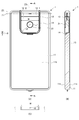
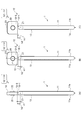
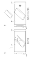
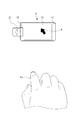
- FIG. 1 is a diagram showing an external configuration of an embodiment of an information processing terminal according to the present invention.
- FIG. 1A is a front view of the information processing terminal.
- FIG. 1B is a top view of the information processing terminal 1.
- FIG. 1C is a left side view of the information processing terminal.
- the information processing terminal 1 includes at least a display function and a digital camera function, and includes a main body part 11 and a connection part 12, which are connected to each other so as to be freely rotatable.
- the main body 11 is a first housing that is formed in a rectangular columnar shape having a planar shape and incorporates various substrates and the like. On a predetermined surface 11 a (hereinafter referred to as “front surface 11 a”) of the main body 11, a display unit 13 configured by a touch panel display or the like is disposed.
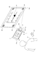
- FIG. 2 is a diagram showing an external configuration of the information processing terminal shown in FIG.
- FIG. 2A is a rear view of the information processing terminal.
- FIG. 2B is a cross-sectional view taken along line AA in FIG.
- FIG. 2C is a cross-sectional view of FIG. 2A as viewed from above.
- the back surface 11b of the main body 11 is one surface facing the front surface 11a described above with reference to FIG.
- the connecting portion 12 is formed in a substantially rectangular shape in plan view, and is rotatably disposed on one short side of the back surface 11 b of the main body portion 11.
- the connecting unit 12 includes a camera base 12-1 and a camera directing unit 12-2.
- a circular camera 21 is disposed in front of the camera directing unit 12-2 (the surface that can be seen in FIG. 2A). That is, the connecting portion 12 is a second housing that houses the camera 21.
- the camera 21 is an imaging unit that images a subject.
- a captured image including the subject imaged by the camera 21 is displayed on the display unit 13.
- the recess width W is the width of the recess for the camera unit.
- the rotation radius r2 is the longest rotation radius from the rotation axis (center) of the second hinge.
- the relationship between the recess width W and the rotation radius r2 is expressed by the following equation (1). W / 2> r2 (1)
- the camera base 12-1 is pivotally supported so that the entire connecting portion 12 can be rotated with respect to the main body 11 around the rotation axis Z1. More specifically, the camera base 12-1 is configured to be rotatable about the rotation axis Z1 while the end surface of the columnar outer shape is in sliding contact with the main body 11.
- the shaft support penetrates between both end surfaces.
- the shafts may be supported by both ends by inserting rotational shafts from both end surfaces, and may be supported by cantilever.
- the camera directing unit 12-2 on which the camera 21 is mounted is cantilevered with respect to the camera base 12-1 around a rotation axis Z3 disposed substantially orthogonal to the rotation axis Z1. It is pivotally supported.
- the arrangement direction of the camera 21 is approximately 90 degrees with respect to the rotation axis Z3. That is, the camera 21 can take a motion on a solid angle with respect to the main body portion 11 by two substantially orthogonal rotation axes that are the rotation axis Z1 and the rotation axis Z3.
- a connecting portion 12 is a portion that directly or indirectly connects the camera 21 so as to be rotatable relative to the main body portion 11 by a plurality of rotating shafts including the axis Z3.
- the connecting part 12 has one or more movable parts having a smaller volume than the main body part 11.
- a camera base 12-1 and a camera directing unit 12-2 are provided as such movable parts.
- the camera 21 serving as the imaging unit may be disposed on a predetermined surface of one or more movable units. In this example, the camera 21 is disposed in front of the camera directing unit 12-2 as described above.
- the angle formed by the direction of the rotation axis Z1 and the direction of the rotation axis Z3 is approximately 90 degrees.
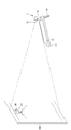
- the information processing terminal 1 is further provided with a stand 14 so that the information processing terminal 1 can be placed on a desk or the like.
- the stand 14 is pivotally supported with respect to the main body 11 about the rotation axis Z2 as a rotation center. That is, the stand 14 is formed in a frame shape, and makes the information processing terminal 1 self-supporting and stable on a horizontal plane by forming a suitable arbitrary angle with the main body 11 by turning about the rotation axis Z2 (described later). See FIG.
- the planar shape substantially U-shape shown in the figure is an example, and it is needless to say that the planar shape may be substantially U-shaped. Furthermore, if it can be used on a vertical surface, which will be described later, it may have a planar hook shape.
- the space efficiency can be significantly improved as compared with the case where the stand 14 and the connecting portion 12 are separately disposed at positions, and the information processing terminal is wasted. It is possible to prevent the case 1 from becoming large. Alternatively, the internal substrate can be prevented from being divided unnecessarily. It should be noted that the connecting portion 12 and the stand 14 substantially share a center line with respect to both end surfaces with respect to the rotation axis as indicated by a line AA.
- the rotation axis Z1 is the rotation center of the connecting shaft between the main body 11 and the connecting portion 12.
- the rotation range of the rotation axis Z1 is approximately 180 degrees or more from the back surface 11b, and desirably exceeds 270 degrees.
- the rotation axis Z ⁇ b> 2 is the rotation center of the connection axis between the main body 11 and the stand 14. It is desirable that the rotation range of the rotation axis Z2 reaches 180 degrees from the back surface 11b. In particular, an arbitrary angle from the back surface 11b to 90 degrees is opposed to the self-weight moment of the information processing terminal 1 on the horizontal plane. A moderate rotation resistance is given so that it can be maintained. As a result, the user can place the information processing terminal 1 in a self-supporting and stable manner at a desired angular posture on a horizontal plane.
- part offset by the rotation axis Z2 side of the stand 14 may be provided, and the rotation center of the rotation axis Z1 and the rotation axis Z2 may be shared.
- the rotation axis Z3 is the rotation center of the connection shaft between the camera base 12-1 and the camera directing unit 12-2.
- the rotation axis Z3 is provided substantially orthogonal to the rotation axis Z1, and rotates on a substantially orthogonal plane around the rotation axis Z1. It is desirable that the rotation range of the rotation axis Z3 reaches 180 degrees each from the substantially orthogonal plane around the rotation axis Z1 around which the rotation axis Z3 rotates.
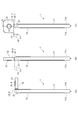
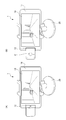
- FIG. 3 is a diagram illustrating a state where the connecting portion of the information processing terminal in FIG. 1 is rotated.
- the connecting portion 12 (more precisely, the camera base 12-1) of the information processing terminal 1 of FIG. 1 is in a state of being rotated 90 degrees about the rotation axis Z1.
- the connecting portion 12 (more precisely, the camera base 12-1) further rotates about the rotation axis Z1 from the state of FIG. 3A, and about the rotation axis Z1. It is in a state of being rotated 180 degrees.
- the connecting portion 12 (more precisely, the camera directing portion 12-2) is further rotated 90 degrees around the rotation axis Z3 from the state of FIG. 3B. .
- FIG. 3A the connecting portion 12 (more precisely, the camera base 12-1) of the information processing terminal 1 of FIG. 1 is in a state of being rotated 90 degrees about the rotation axis Z1.
- the connecting portion 12 (more precisely, the camera directing portion 12-2) is further rotated 90 degrees around the rotation axis Z3 from the state
- the distance h ⁇ b> 1 is from the rotation axis (center) of the first-axis hinge to the upper side surface of the main body 11 of the information processing terminal 1 (smartphone). This is the longest distance to the top surface of the terminal 1 (the one with the display unit 13) or the bottom surface of the information processing terminal 1 (the one without the display unit 13).
- the distance h2 is a distance from the rotation axis (center) of the first-axis hinge to the rotation section of the second-axis hinge.
- the relationship between the distance h1 and the distance h2 is a relationship represented by the following expression (2). h2> h1 (2)
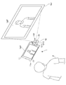
- FIG. 4 is a diagram illustrating a state in which the stand 14 of the information processing terminal 1 in FIG. 1 is rotated.
- FIG. 4A is the same state as FIG. 3B described above, and the stand 14 is not rotated and is housed in the main body 11.
- the stand 14 is further rotated about the rotation axis Z2 from the state of FIG. 4A, and is rotated 180 degrees about the rotation axis Z2.
- the relationship between the distance h1 and the distance h2 is the same as that in the above equation (2).
- the user turns the stand 14 180 degrees about the rotation axis Z2 so that the user can clip the stand 14 to the wall KB as shown in FIG. 4 (C).
- the information processing terminal 1 can be attached to the wall KB by applying to CL or the like.
- the optical axis direction of the camera 21 photographing direction of the subject
- the normal direction of the display unit 13 the direction in which the user views the display unit 13
- the user can easily take a picture of himself as a subject, that is, take a selfie shot (self-portrait) while viewing the camera viewpoint image (an image of himself / herself) by facing the wall KB. .
- the stand 14 is rotated with respect to the main body 11 by the rotation axis Z2, and the camera 21 (the connecting portion 12) is rotated by the two axes of the rotation axis Z1 and the rotation axis Z3. Part 11).
- the user can also use the information processing terminal 1 over the wall KB as shown in FIG. 4 when performing a selfie shot (self-taking) or the like, or use the information processing terminal 1 as shown in FIG. It can also be used by leaning on a table.
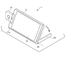
- FIG. 5 is a diagram illustrating a state where the information processing terminal 1 of FIG. 1 is used while standing on a table.
- FIG. 5A is a perspective view from the viewpoint of viewing the front surface 11a side where the display unit 13 is disposed.
- FIG. 5B is a perspective view showing a usage pattern on the desk of the information processing terminal of FIG. 1 as seen from the back surface 11b side on which the display unit 13 is arranged.
- the stand 14 in this embodiment is in a state of being rotated within 90 degrees about the rotation axis Z2 from the state of FIG.
- the rotation axis Z2 is given an appropriate rotation resistance so that an arbitrary angle of 90 degrees from the back surface 11b can be maintained against the self-weight moment of the information processing terminal 1 on the horizontal plane. As a result, the user can place the information processing terminal 1 in a self-supporting and stable manner at a desired angular posture on a horizontal plane.
- the information processing terminal 1 can turn the camera 21 toward the subject by rotating the rotation axis Z1 and the rotation axis Z3.
- the information processing terminal 1 can take a picture without holding the main body part 11 by using the shutter remote control function and the self-timer function together, it can solve various problems described later.
- a solution to this problem is to employ an information processing terminal 1 to which the present invention is applied. That is, since the information processing terminal 1 to which the present invention is applied has the stand 14, it can be fixed to a wall or a table as shown in FIGS. 4 and 5, and a selfie stick becomes unnecessary.
- the unnaturalness may be slightly reduced even if the selfie stick is used, but the unnaturalness may remain, and a pose where the white portion is desired (for example, a pose using both hands) may not be possible.
- a solution to this problem is to employ an information processing terminal 1 to which the present invention is applied. That is, the information processing terminal 1 to which the present invention is applied has a stand 14, a self-timer, and a shutter remote control function. Therefore, the information processing terminal 1 can be fixed to a wall or a table as shown in FIGS. Is no longer necessary.
- the information processing terminal 1 to which the present invention is applied has a stand 14 and a two-axis rotation mechanism of the camera, so that it can be fixed on a wall or a table as shown in FIGS. The hands of people other than the target are no longer needed.
- the information processing terminal 1 to which the present invention is applied has a stand 14 and a biaxial rotation mechanism of the camera, and can be fixed to a wall or a table as shown in FIGS. Is no longer necessary.
- the stand 14 is set up as shown in FIG. 9 and the connecting portion 12 is rotated by 180 degrees or more, so that the camera can be shot in a fixed state on the table, eliminating the need for a tripod. . In this case, it is not always necessary to stand the stand 14.
- the information processing terminal 1 to which the present invention is applied has a stand 14 and a camera rotation mechanism, so that it can be fixed to a wall or a table as shown in FIGS. It is no longer necessary to have.
- stand 14 as shown in FIG. 9 and rotate the connecting part 12 by 180 degrees or more to fix it on the desktop. You can shoot, so you don't have to hold your smartphone. In this case, it is not always necessary to stand the stand 14.
- the information processing terminal 1 to which the present invention has a stand 14 and a two-axis rotation mechanism of the camera, so that the rear camera is turned to the front by two-axis rotation as shown in FIGS. It is possible to wrap around and direct at any angle, and a front camera with a fixed angle becomes unnecessary.
- the stand 14 is raised as shown in FIG. 9 and the connecting portion 12 is rotated by 180 degrees or more, so that it can be taken in a fixed state on the table, so the angle is fixed.
- a front camera is not required. In this case, it is not always necessary to stand the stand 14.
- a solution to this problem is to employ an information processing terminal 1 to which the present invention is applied. That is, the information processing terminal 1 to which the present invention is applied utilizes the gap provided between the stand 14 and the connecting portion 12 by turning the connecting portion 12 and the stand 14 180 degrees.
- the information processing terminal 1 to which the present invention is applied utilizes the gap provided between the stand 14 and the connecting portion 12 by turning the connecting portion 12 and the stand 14 180 degrees.
- it since it can be suspended and supported on a flat surface using a projection or a pin-like member, it is suitable for use on a wall, and it is not necessary to separately provide a hook.
- the front camera is generally compared to the rear camera,
- A Low resolution
- B Low sensitivity (Cannot shoot without flash in dark scenes)
- C There is a fixed focus that is not autofocus.
- D There is an autofocus type, but the autofocus speed is slow
- e Low zoom magnification
- Many things are inferior in performance without a flashlight , I can not capture images with beautiful image quality.
- the rear camera and front camera have different performance, it is necessary to develop two cameras for one model.
- the usability such as navigating by voice is very bad.
- a solution to this problem is to employ an information processing terminal 1 to which the present invention is applied. That is, the information processing terminal 1 to which the present invention is applied can point the camera 21 as a high-performance camera in any direction with respect to the terminal body, and can freely view the camera viewpoint image while viewing the camera viewpoint image. Therefore, application software for taking a selfie shot without looking at the display unit 13 becomes unnecessary.
- the stand and the rotary camera which are the above solutions also require the respective axes for rotation on the main body side, and it is necessary to secure a space for the two axes. Will become bigger.
- the camera depending on how the camera is rotated, even if the camera of a smartphone that stands up on the stand rotates, the camera is often not suitable for the subject, which is often not a solution.
- it is possible to further increase the rotation axis so that the camera is directed to the subject it is often troublesome to always take a picture after the camera is pointed at the subject.
- a solution to this problem is to employ an information processing terminal 1 to which the present invention is applied. That is, the information processing terminal 1 to which the present invention is applied may use both the stand 14 and the rotation axis of the camera 21, so that the camera is always attached to the subject only by two-axis rotation as shown in FIGS. 4 and 5. 21 can be directed, and it is not necessary to increase the rotation axis.
- the display unit faces downward, and it is impossible to take a picture while viewing the camera viewpoint image.
- the orientation of the camera and the orientation of the display unit can be set separately, so that it is possible to shoot while viewing the camera viewpoint image.
- the vertical direction of the screen may change. However, if no effort is made, the vertical direction may be reversed. In such high-angle shots and low-angle shots, if the camera rotates in a fixed direction (for example, it rotates only clockwise from the normal position), it is difficult to shoot, so it can be rotated in both directions. It is desirable.
- a solution to this problem is to employ an information processing terminal 1 to which the present invention is applied. That is, the information processing terminal 1 to which the present invention is applied has the biaxial rotation mechanism of the stand 14 and the camera 21, so that the rear camera 21 is biaxially rotated as shown in FIGS. Therefore, it is possible to direct the light up and down freely, and a rear camera with a fixed angle becomes unnecessary.
- the angle of view wide angle, normal angle, narrow angle, etc.
- the distance to the subject is often short on the optical axis direction side of the front camera, so it is desired to shoot at a wide angle, but on the optical axis direction side of the rear camera, it is desired to shoot at a normal or narrow angle. Therefore, it is desirable that the angle of view automatically changes depending on the direction of the camera.
- a solution to this problem is to employ an information processing terminal 1 to which the present invention is applied. That is, since the information processing terminal 1 to which the present invention is applied has a shutter remote control function, when taking a selfie shot as shown in FIGS. 4 and 5, the shutter is not pressed without pressing the shutter button or the touch panel. Can be taken down, and it becomes unnecessary to hold the smartphone firmly.
- the information processing terminal 1 described above is installed on a desk or the like, the camera 21 is rotated toward the 10 people, When it is far away from the information processing terminal 1, the display unit 13 is too small to be seen, and it may be difficult to release the shutter because it is not possible to know whether everyone is in the frame of the camera viewpoint image or to understand each expression. is there. That is, there is a problem that the user wants to take a photograph while confirming the camera viewpoint image by some method.
- the solution to this problem is to employ the following technique.
- a screen sharing function that allows the camera viewpoint image to be transferred to another information processing terminal such as a smartphone or personal computer by wire or wireless to the information processing terminal 1 to which the present invention is applied, and enables operation. It is good to adopt the method of mounting. Thereby, it becomes possible to shoot a still image or a moving image from a remote position while sharing the camera viewpoint image of the information processing terminal 1 with other information processing terminals.
- the information processing terminals are directly connected to each other.
- the Internet the camera viewpoint image of the information processing terminal 1 placed at home is shared with the office personal computer, and the home screen is viewed while viewing the personal computer screen. It is also possible to take pictures of the remaining pets.
- a conventional digital camera or smartphone can also take a combined panoramic shot by moving the camera laterally. However, it is necessary to shoot while moving the smartphone or camera in various directions, and it is often impossible to synthesize beautifully.
- a solution to this problem is to employ an information processing terminal 1 to which the present invention is applied. That is, in the information processing terminal 1 to which the present invention is applied, the rotation about the rotation axes Z1 and Z3 of the camera 21 may be electric. Therefore, as shown in FIG. Therefore, it is not necessary to move the camera 21 laterally.
- gesture recognition cameras are very expensive and incur additional costs.
- a solution to this problem is to employ an information processing terminal 1 to which the present invention is applied.
- the information processing terminal 1 to which the present invention is applied is possible if the camera 21 facing the person has a high function (for example, gesture recognition of an exhibition), and a camera dedicated to gesture recognition is not necessary.
- the navigation can be used immediately without taking time to recognize the direction by a user interface in which an arrow is superimposed on an image actually captured by a camera.
- a user interface in which an arrow is superimposed on an image actually captured by a camera.
- the image of the rotated camera 21 can be displayed on the display unit 13 as one of the windows, and the presence of an obstacle can be transmitted by sound, screen or vibration, thereby avoiding danger. .
- a solution to this problem is to employ an information processing terminal 1 to which the present invention is applied. That is, the information processing terminal 1 to which the present invention is applied may be able to lock the rotation of the camera 21 at a specific angle. If the main body 11 is held and stabilized, the camera 21 is also stabilized.
- the information processing terminal 1 to which the present invention is applied can point the camera 21 in any direction with respect to the terminal body, and displays a camera viewpoint image on a part of the screen while displaying a navigation map. Since it can be displayed in a form like Picture in Picture, it can be used for other purposes at the same time while using a smartphone as a drive recorder. Therefore, a dedicated drive recorder becomes unnecessary.
- the installation in the car is installed so that it is a landscape screen, but the installation in a bicycle is installed so that it is a portrait screen, so the camera 21 can be rotated in two axes, so it can be used in a wide variety of ways. Is possible.
- a solution to this problem is to employ an information processing terminal 1 to which the present invention is applied.
- the information processing terminal 1 to which the present invention is applied is supposed to be applied to a stereo camera, and if there is a rotating camera 21, it can be solved, and it is not necessary to add a function to the front camera. .
- the connecting portion 12 is configured by two movable portions, that is, the camera base portion 12-1 and the camera directing portion 12-2.
- the connecting portion 12 is not particularly limited to the above-described embodiment, and the main body portion. It is sufficient to have one or more movable parts having a volume smaller than 11. In this case, it is sufficient that the camera 21 serving as the imaging unit is disposed on a predetermined surface of one or more movable units.
- a device having an arbitrary function can be mounted on an arbitrary number of arbitrary types of movable units (including a movable unit in which an imaging unit is arranged) among one or more movable units.
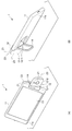
- FIG. 6 is a diagram showing an embodiment of the information processing terminal according to the present invention, in which a connecting portion of an embodiment different from FIG. 1 is rotated.
- the connecting portion 12 (more precisely, the camera base 12-1) of the information processing terminal 1 in FIG. 1 is in a state of being rotated 180 degrees around the rotation axis Z1.
- the connecting portion 12 (more precisely, the camera directing portion 12-2) is further centered on the rotation axis Z3 from the state of FIG. 6A (as viewed from the front surface 11a side of the main body portion 11). ) It is in a state rotated 90 degrees to the right.
- a circular camera 21 is arranged at the approximate center of the front of the camera directing unit 12-2 (the surface on the side visible in FIG. 6B).
- the connecting portion 12 (more precisely, the camera directing portion 12-2) is further centered on the rotation axis Z3 from the state of FIG. 6A (as viewed from the front surface 11a side of the main body portion 11). ) Turned 90 degrees to the left. As shown in FIG. 6C, a circular shape is formed at the approximate center of the back surface (the surface facing the front surface and seen in FIG. 6C) of the camera directing unit 12-2. A projector 22 is arranged. Further, as in FIG. 3, the relationship between the distance h1 and the distance h2 is the same as that in the above equation (2).
- the stand 14 is rotated with respect to the main body 11 by the rotation axis Z2, and the camera 21 (the connecting portion 12) is rotated by the two axes of the rotation axis Z1 and the rotation axis Z3. ) Rotates relative to the display unit 13 (main body unit 11). For this reason, the user can also lean and use the information processing terminal 1 on the table as shown in FIG. 7 when taking a selfie shot (self-taking) or the like.
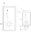
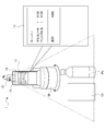
- FIG. 7 is a diagram illustrating a state in which the information processing terminal 1 of FIG. 6 is used while standing on a table.
- the camera 21 images the user U.
- the captured image of the camera 21, that is, the camera viewpoint image including the image Ug ⁇ b> 1 of the user U is displayed on the display unit 13.
- the camera directing unit 12-2 is provided with a projector 22 on the back surface facing the front surface on which the camera 21 is placed. Accordingly, the projector 22 can also project a captured image of the camera 21, that is, a camera viewpoint image including the image Ug2 of the user U on the screen Scr.
- the camera viewpoint image can be viewed by the user U through the display unit 13 and can also be viewed by another person (not shown) through the screen Scr.
- the image displayed on the display unit 13 and the image projected on the screen Scr by the projector 22 are not necessarily matched as in the example of FIG. 7, and may be different images.
- the image of the user U (camera viewpoint image of the camera 21) is displayed on one of the display unit 13 and the screen Scr, and the other party's caller is displayed on the other.
- An image may be displayed.
- the camera 21 and the projector 22 may be arranged on the same surface or on different surfaces, without being arranged at the positions where the connecting portions 12 face each other.
- the imaging direction of the camera 21 and the projection direction of the projector 22 are One will be restricted. Therefore, although not shown, a movable part different from the camera directing part 12-2 may be provided, and the projector 22 may be mounted on the movable part. As a result, the imaging direction of the camera 21 and the projection direction of the projector 22 can be independently directed in arbitrary directions.
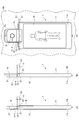
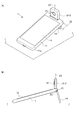
- FIG. 8 is a diagram showing an information processing terminal according to an embodiment of the present invention, which is used on a desk according to an embodiment different from FIGS. 1 and 6.
- the stand 23 is rotated about 50 degrees toward the back surface 11b around the rotation axis Z4, and is erected on the table.
- the axis Z3 is also rotated, and the camera 21 is in a state that enables selfie shots (self-taking).
- the stand 23 has substantially the same outer dimensions as the short side of the main body 11, and is integrated with the main body 11 in an morphological manner by setting the opening with the main body 11 to zero degrees. Configure the lower end.
- the rotation axis Z4 connects the main body 11 and the stand 23 at one corner of the main body 11 so as to be rotatable.
- the rotation axis Z4 has an axial direction substantially parallel to the long side of the main body 11.
- Appropriate rotation resistance is given so as to be independent and stable against the self-weight moment of the information processing terminal 1. Furthermore, you may provide the location which rotation can be stopped on the way in several places within the opening degree of 90 degree
- the rotation axis Z4 can rotate the stand 23 at least within 90 degrees on the back surface 11b side, and the opening degree of the main body 11 and the stand 23 can be set to zero degrees as described above.
- the rotation axis Z4 has an axial direction substantially parallel to the long side of the main body 11, so that the user can perform a selfie shot (self-taking) or the like as shown in FIG.
- the rotation angle of the rotation axis Z4 when the 1 is placed on the table and used in the horizontal position (landscape) coincides with the standing angle of the main body 11, and the adjustment of the angle is easy.
- the stand 23 can be brought into the use state shown in FIG. 8 by causing the main body 11 side while the information processing terminal 1 is placed on the table top from the table placed on the table. Further, by gently pressing the main body 11 side against the desk surface from this state, it is possible to shift to a more stable flat state without lifting the information processing terminal 1.
- the angle of the stand 23 can be finely adjusted, if the subject is above the front camera or the single-axis rotating camera, the camera can be perfectly pointed at the subject even if it is not a two-axis camera. It becomes possible.
- FIG. 9 is a diagram illustrating a state in which the information processing terminal of FIG.
- FIG. 9A is a perspective view showing a state in which the table is used in a vertical position (portrait) on a table.
- FIG. 9 (B) is a side view showing a state in which the computer is stood and used in a vertical position (portrait).
- the stand 14 is rotated about 90 degrees toward the back surface 11b around the rotation axis Z2, is erected on the table, and the rotation axis Z1 is also rotated.
- the camera 21 is in a state in which it can be selfie shot (self-portrait) in a vertical position (portrait).
- the receiving side can also be held vertically or horizontally depending on whether the communication partner is capturing vertically or horizontally. Can be changed.
- the other party of the communication is taking a picture in a vertical position, but the user cannot take a selfie while the information processing terminal 1 is erected in the vertical position, the user on the side of the information processing terminal 1 Must be held by hand, or the other party should be held vertically to force side-by-side shooting, or both must accept that each other's images are displayed on the display section as small or out of place. Disappear.
- the information processing terminal 1 of FIG. 1 includes the stand 14 and the rotation mechanism of the photographing unit, even if there is no fixture such as a projection or a thumbtack that can be supported by hanging around the appropriate wall surface. It is possible to take a self-portrait by standing in a vertical position (portrait) on the table. As a result, the burden of holding the information processing terminal 1 by hand in the vertical position (portrait) and camera shake during hand-held imaging, etc. It will be freed from various problems at once.
- a mechanism may be employed in which an “open button” for automatically rotating the rotation axis Z1 is provided at a position where the pressing operation is easy such as a side surface of the main body 11 and the connecting portion 12 is easily raised by the pressing operation. .
- the camera is fixed on a tripod and taken at regular intervals, but there is a problem that a lot of equipment such as a tripod is required.
- a lot of equipment such as a tripod is required.
- there is a demand to move the camera in accordance with the movement of the sun for example, instead of fixing the camera completely during time-lapse shooting.
- Such additional equipment is required, and the setting is also required separately from the camera.
- the information processing terminal 1 has a biaxial rotation mechanism as shown in FIGS.
- the camera 21 can be fixed and a time-lapse photo or video of the Sun Sun visible from the window MD can be taken without using additional fixing equipment such as a tripod.
- the information processing terminal 1 shown in FIG. 10 has a plurality of rotation shafts such as the rotation shafts Z1 to Z4 described above, it does not require additional equipment such as a dolly, and is similar to the Sun Sun. It is possible to take time-lapse photos and videos by presetting the camera to move according to the movement of the moving object at low speed.
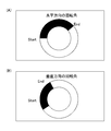
- the information processing terminal 1 can rotate the camera in the horizontal direction at an angle as shown in FIG. 11A, and the camera in the vertical direction at an angle as shown in FIG. It is possible to rotate.
- the information processing terminal 1 can cleanly or blur only the background of the captured image. is there.
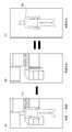
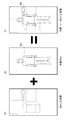
- an image including the object Obj is photographed as shown in FIG. 12A, and an image of only the background where the object Obj is not photographed before and after that is photographed as shown in FIG. Furthermore, by leaving only the difference between the image in FIG. 12A and the image in FIG. 12B, an image in which only the target Obj such as a product or a person is left can be created as shown in FIG. 12C. . Also, if an image in which only the object Obj is left as shown in FIG. 12C can be created, the image is combined with an image obtained by blurring the background only image as shown in FIG. As shown in FIG. 13F, an image with a beautifully blurred background can be created. It should be noted that even moving images can be displayed by moving in the same way as images, and can be used for video analysis of security cameras.
- the information processing terminal 1 can display past photo data translucently, or select a photo to be compared from the live view screen of the camera to be shot with one button. It can be displayed and automatically returned to the live view screen of the camera, or it can be returned to the live view screen of the camera with one action (pressing a button, pressing a button on the remote control, operating with a voice, etc.). It becomes possible to take comparative pictures.
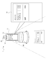
- the video displayed on the display unit 13 of the information processing terminal 1 is displayed on a large screen on a TV or projector wirelessly or by wire.
- the operation can be performed by a device that can be displayed on the screen such as the laser pointer LP.
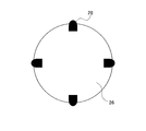
- three or more markers 24 can be displayed as part of the image on the screen Scr.
- the camera 21 of the information processing terminal 1 captures the cursor P of the laser pointer LP and three or more markers 24, so that the relative positional relationship between the image on the screen Scr and the cursor P can be obtained.
- the laser pointer LP may be provided with a button for enlarging / reducing the cursor P, and the enlargement / reduction button is integrated with the On / Off button of the cursor P. May be used. Changes such as changing the color or shape of the cursor may be added when the screen is enlarged or reduced.
- the number of cursors P is not limited to one, and a plurality of cursors P may be simultaneously determined. At the time of enlargement or reduction operation, it can be determined that the image is enlarged when the two points are separated, and the image is reduced when the two points are approached.
- the video on the display unit 13 that is output to a TV or a projector and the video on the screen that is displayed on the TV or the projector and the cursor P is also displayed in real time.
- the display unit 13 of the information processing terminal 1 and the screen output to the television receiver or projector do not necessarily match.
- the image captured by the camera 21 may be displayed on the display unit 13 of the information processing terminal 1, or nothing may be displayed for the purpose of lightening the processing.
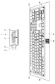
- the information processing terminal 1 shown in FIG. 16 uses the stand 14 to stand the information processing terminal 1, uses the rotation mechanism of the two-axis camera, fixes the camera 21, shoots the printed keyboard K, and A finger placed on K is photographed with a camera, and the position of the pressed finger can be detected.
- QR code registered trademark
- the button area of the keyboard K can be specified, the relative position of the button with the key pressed can be determined, and the finger position on the printed keyboard K can be determined.
- Character input is possible by pressing.
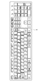
- the keyboard K having a general arrangement as shown in FIG. 17, but since the keyboard K can be manufactured by printing, it can be customized as much as desired without worrying about the sales volume. .
- buttons such as “Good morning.” “Ichiro Suzuki.” “Is.” “I ’ll get you”, I ’d like you to enter them in a unit of words instead of entering them one by one. Is also possible.
- game pads, musical instruments, video editing mixers, DJ mixers, musical instruments can also be printed. You can also input handwritten characters and illustrations by shooting with your camera.
- the camera 21 captures the movement of the finger Fn and the touch operation to the desk without directly operating the information processing terminal 1.
- the movement of the finger Fn is linked with the movement of the cursor P, and the operation can be performed in the same manner as when the touch pad of the personal computer is operated.
- the operation can be performed in the same manner as when moving with the jog dial of the mouse. It becomes possible to input handwritten characters in the same manner.
- the information processing terminal 1 includes a camera 21 that can be rotated about a plurality of rotation axes. Have. For this reason, the information processing terminal 1 is fixed by the navigation stand 25, and the camera 21 is used to shoot an image of the traveling direction of the car as an AR navigation or a drive recorder, and at the same time, the display unit 13 of the information processing terminal 1 is at an angle that is easy for the driver to see Can be directed.
- the camera 21 of the information processing terminal 1 normally captures the traveling direction as shown in FIG. As shown in FIG. 20 (B), the camera 21 rotates to photograph the driver's face and the like, and the driver's health condition can be checked.
- the current photographed image as shown in FIG. 21A is compared with the previous photograph as shown in FIG.
- the camera 21 and the rotary cradle 26 are adjusted by electric rotation so that the target Obj is at an appropriate position, or a guide for determining the pose is shown on the display unit 13 so that the same pose is obtained.
- a guide for example, a handwritten input can be displayed.
- the camera 21 always uses a rotation axis Z1 in a certain direction (for example, horizontal direction).
- the image displayed on the display unit 13 of the information processing terminal 1 can be kept constant by performing the electrical control using the G sensor data or the like so as to face.
- the book B is photographed by the camera 21 and is subjected to OCR, thereby recognizing text data and translating the information processing terminal 1. Can be displayed on the display unit 13.
- Each page of book B is photographed as a still image or a movie without pressing the shutter button, and translation is performed with the page being turned as a trigger.
- the page can be reloaded by voice or by sound.
- the information processing terminal 1 has a plurality of pivot axes in the connecting portion 12, the angle of the camera 21 can be changed without depending on the orientation of the display portion 13, so that this function is possible.
- the information processing terminal 1 on the rotary cradle 26, it is possible to earn a distance in the height direction, making it easy to take a picture, and rotating the rotary cradle 26 and each time of the information processing terminal 1.
- the direction of the camera 21 can be appropriately adjusted to the book B to be photographed, so that text data can be made with higher accuracy.
- the cash register used for accounting at a store is generally for business use, but it is very expensive, and it is read by a bar code reader of the product or detects an IC tag attached to the product. Therefore, a process of inputting product information to the cash register is required. In particular, in the case of bar code input, it may take time to align the position of the bar code, so it is necessary to master the bar code input operation. Individually managed bakers cannot put a barcode on the bread itself, so the store clerk manually inputs the product buttons at the cash register.
- the information processing terminal 1 that can rotate the camera 21 is used, or the information processing terminal 1 is placed on the rotary cradle 26.
- the orientation of the camera 21 automatically changes according to the position of the barcode, and for example, the barcode of the product to be purchased such as chocolate Ch or plastic bottle Pb is high. It becomes possible to read with accuracy.
- the shape of the product in advance, it is possible to know information such as the product name and price even for a product without a barcode such as bread.
- the information processing terminal 1 capable of rotating the camera 21 is placed on the rotary cradle 26 on the desk, thereby increasing
- the rotation of the rotary cradle 26 and the rotation of the information processing terminal 1 it is possible to earn a distance in the direction and operate each receipt on the desk (such as pressing a shutter). You can shoot automatically without having to.
- the rotary cradle 26 is not necessarily required.
- OCR optical character recognition
- the text data can be recognized and input. The user does not need to operate the information processing terminal 1 or the rotary cradle 26, and only has to concentrate on placing a receipt or a receipt. Receipts and receipts are easy to line up, especially on a desk-like plane.
- the information processing terminal of the present invention by fixing the top surface attachment to the rotary cradle 26, the product to be photographed is placed on the rotary cradle 26, While using the camera 21 of the information processing terminal 1 fixed by the stand 14, the rotation of the rotary cradle 26 is controlled from the information processing terminal 1, and 360 degree product photography is possible.
- a hanging attachment 27 is fixed to the rotary cradle 26, so that a thing is placed under the rotary cradle 26 with a hanger or the like. It becomes possible to hang.
- the rotation of the rotary cradle 26 is controlled from the information processing terminal 1 so that 360 degree product photography can be performed.
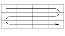
- a panoramic shot can be taken by moving the camera laterally even with a digital camera or smartphone, but it is often necessary to move the camera or smartphone smoothly and laterally, making it impossible to synthesize beautifully.
- you can move not only horizontally but also vertically you can synthesize even larger photos, but this is also not beautiful.
- the information processing terminal of the present invention by operating the camera 21 of the information processing terminal 1 by moving a plurality of rotation axes, as shown in FIG. Panorama shooting is possible, and larger photos can be taken. Furthermore, by placing the information processing terminal 1 on the rotary cradle 26, the photographing point is moved in the vertical direction using the rotation axis of the information processing terminal 1, and the horizontal rotation of the rotary cradle 26 is used. Thus, a wider area can be photographed than when only the rotation axis of the information processing terminal 1 is used. Since it can be shot electrically, it can be combined beautifully. If vertical and horizontal composition is possible, you can take larger photos. When scanning, if you decide the order of scanning in the way of a single stroke, there is no waste.
- the camera 21 of the information processing terminal 1 on the teacher Tc side is rotated, so that the desk is not pushed.
- the book B is automatically photographed, trapezoidally corrected, and upside down, and the book B and the teacher Tc are displayed on the display unit 13 of the student information processing terminal 1 as shown in FIG. It is also possible to display faces simultaneously. In that case, when the height from the desk to the camera is insufficient and it is not possible to photograph all the paper, it is preferable to use a stand or the like that can stand the information processing terminal 1 in the vertical direction.
- the rotary cradle 26 a distance in the height direction can be obtained, and the camera rotation function of the information processing terminal 1 is used for the vertical rotation of the camera, and the horizontal rotation of the rotary cradle 26 is adjusted. A wider area than the rotation of the information processing terminal 1 can be taken.
- the information processing terminal 1 capable of rotating the camera 21 is placed on the rotary cradle 26 on the desk, thereby rotating the information processing terminal 1.
- the camera 21 can be directed in all directions.
- the camera 21 is rotated after the position of the person is specified by the human sensation sensor 28 built in the rotary cradle 26 or the information processing terminal 1, so that the person can be moved without rotating. It becomes possible to shoot well. Even if there is no rotary cradle 26, if there is the camera 21 of the information processing terminal 1 that can rotate more than two axes, automatic photographing becomes possible.
- the position can be specified by calculating a subtle time difference when sound enters the microphone.
- a rotation mechanism By applying a rotation mechanism, an object can be determined and the camera can be automatically tracked. Shooting is not necessarily performed automatically, and may be performed with a voice or a gesture. If there is a person who does not want to take a picture by judging the person, it is possible to set so that the picture is automatically taken and no picture is taken. It is also possible to make a judgment by image processing such as not registering a person who does not want to take a picture with a camera in advance or making a cross mark by hand during shooting.
- the cradle In order to operate the functions built into the cradle, the cradle is not able to receive power from the smartphone because it is one of the main purposes to supply the smartphone with power for charging. Power supply such as a battery and an AC adapter is required, and the battery and the AC adapter must be carried for a very short time.
- the information processing terminal of the present invention it is automatically determined that power is not supplied to the rotary cradle 26, and power is supplied from the information processing terminal 1 to the rotary cradle 26.
- Functions such as the human sensor 28 attached to the rotary cradle 26 can be moved by the power source of the information processing terminal 1.
- an HDMI (registered trademark) terminal may be attached to enable video output, or a USB A terminal may be included, which may include various functions in the cradle. is there.
- a USB A terminal may be included, which may include various functions in the cradle.
- the in-camera of the personal computer is attached to the top or bottom of the display, and if you point the display, you will face the in-camera
- the face faces the connected monitor, so you do not always see the smartphone placed in the cradle, and the angle at which the in-camera faces depends on the angle of the cradle. Therefore, it is necessary to change the position and orientation of the cradle of the smartphone.
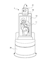
- the information processing terminal of the present invention when the information processing terminal 1 is placed on the rotary cradle 26 with the human sensor 28 as shown in FIG.
- the rotating cradle 26 and the rotation shaft of the information processing terminal 1 are driven so that the photographing target can be accommodated in the camera 21, and the photographing subject can be accommodated in the camera.
- the photographing target can be accommodated in the camera 21
- the photographing subject can be accommodated in the camera.
- it can it be used like an in-camera on a personal computer, but it can also be used for various purposes such as using the video of the camera 21 for face authentication, or using the human sensor 28 to turn off the monitor when no one is present. .
- Such a rotary cradle 26 can include, for example, a plurality of microphones, a plurality of speakers, a plurality of human sensors, a swivel function, a mobile battery, and the like.
- the information processing terminal mounted on the rotary cradle 26 is linked with information display, music playback, news playback, weather forecast, audio book, calendar, sports bulletin, traffic information, shopping, electricity, air conditioner, and curtain. It becomes possible to use it for various things.
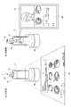
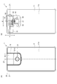
- FIG. 32 shows an external appearance and an internal configuration of an embodiment of the information processing terminal according to the present invention, which is different from FIG.
- FIG. 32A is a rear view of the information processing terminal.
- FIG. 32B is a cross-sectional view of FIG.
- the connecting unit 12 includes a camera base 12-1 and a camera directing unit 12-2.
- a circular camera 21 is arranged in front of the camera directing unit 12-2 (the surface that can be seen in FIG. 32A).
- the camera base 12-1 is pivotally supported so that the entire connecting portion 12 can be electrically rotated with respect to the main body 11 around the rotation axis Z1. That is, the camera base 12-1 is configured to be able to rotate around the rotation axis Z1 while sliding the end face of the columnar outer shape to the main body 11.
- a stepping motor 51, a biaxial hinge 53, a gear 54, and a gear 55 are provided inside the connecting portion 12 so as to enable automatic rotation about the rotation axis Z1 (see FIG. 32 (b)). That is, when the rotational driving force of the stepping motor 51 is transmitted to the biaxial hinge 53, the camera base 12-1 automatically rotates about the rotation axis Z1.
- the camera directing unit 12-2 on which the camera 21 is mounted is cantilevered with respect to the camera base 12-1 around a rotation axis Z3 disposed substantially orthogonal to the rotation axis Z1. It is pivotally supported.
- a stepping motor 52, a biaxial hinge 53, a gear 54, and a gear 56 are provided inside the connecting portion 12 so as to enable automatic rotation about the rotation axis Z3 (see FIG. 32 (b)). That is, when the rotational driving force of the stepping motor 52 is transmitted to the biaxial hinge 53 via the gear 54 and the gear 56, the camera directing unit 12-2 automatically rotates about the rotation axis Z3.
- the biaxial hinge 53 is not necessarily an integral biaxial hinge, and the hinge may be divided into two.
- the rotation on the rotation axis Z1 and the rotation axis X3 can be electrically performed with high accuracy and at high speed.
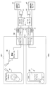
- FIG. 33 is a block diagram showing a configuration for realizing the rotation control on the rotation axis Z1 and the rotation axis Z3 when the stepping motor 51 and the stepping motor 52 of FIG. 32 are employed.
- the motor driver 61 of the stepping motor 51 and the motor driver 62 of the stepping motor 52 are realized in order to realize the rotation control on the rotation axis Z1 and the rotation axis Z3.
- a rotation angle sensor 63 of the stepping motor 51, a rotation angle sensor 64 of the stepping motor 52, an MCU (Micro Controller Unit) 65, and a wireless module 66 are provided.
- the MCU 65 includes a driver 71 serving as an interface with the wireless module 66, a driver 72 serving as an interface with the input device 82 of the information processing terminal 1, a driver 73 serving as an interface with the motor driver 61, and a motor driver 62.
- a driver 74 serving as an interface is provided.
- the MCU 65 is also provided with ADCs (Analog to Digital Converters) 75 and 76 in order to convert the analog detection signals of the rotation angle sensors 63 and 64 into digital signals.
- ADCs Analog to Digital Converters
- a user instruction OP1 using the wireless remote controller 81 or the like and an input device 82 such as a touch panel of the information processing terminal 1 are used as instructions for rotation on the rotation axis Z1 and the rotation axis Z3 (instruction for moving the camera 21).
- the user's instruction OP2 is performed.
- the instruction OP1 is input to the MCU 65 driver 71, and the instruction OP2 is input to the MCU 65 driver 72.
- the MCU 65 executes control for each of the motor drivers 61 and 62 via each of the drivers 73 and 74 based on the instruction by the instruction OP1 and the detection signals of the rotation angle sensors 63 and 64, respectively.
- the first is that the absolute position can be known (because it cannot be obtained by calculation if moved by the user's hand).
- the third point is that the direction of the camera 21 can be accurately calculated by combining the G sensor of the main body and the rotation angle sensors 63 and 64.
- an information processing terminal to which the present invention is applied can take various various embodiments.
- the information processing terminal to which the present invention is applied only needs to have the following configuration, and its embodiment is not particularly limited. That is, an information processing terminal to which the present invention is applied is An imaging unit (e.g., the camera of FIG. 2) that images a subject; A main body in which a display unit (for example, the display unit 13 in FIGS. 1 and 2) that displays a captured image including the subject imaged by the imaging unit is disposed on a predetermined surface (for example, the front surface 11a in FIGS. 1 and 2). Part (for example, main body part 11 in FIG. 1 and FIG. 2), A first rotation axis (for example, the rotation axis Z1 in FIG.
- a connecting portion (directly or indirectly) that allows the imaging unit to be rotated relative to the main body by a plurality of rotating shafts including a rotating shaft (for example, the rotating shaft Z3 in FIG. 2).
- a rotating shaft for example, the rotating shaft Z3 in FIG. 2.
- the connecting portion has one or more movable portions (for example, the camera base portion 12-1 and the camera directing portion 12-2 in FIG. 2) having a smaller volume than the main body portion,
- the imaging unit is disposed on a predetermined surface of a predetermined one of the one or more movable units (for example, the camera directing unit 12-2),
- An angle formed by the direction of the first rotation axis and the direction of the second rotation axis is approximately 90 degrees. Can be.
- main body part and the two or more movable parts are connected by a hinge having two or more axes.
- main body portion and the movable portion are connected by a flexible arm. Can be.
- the camera unit rotates around a rotation axis (for example, the rotation axis Z1) at a position perpendicular to the longitudinal direction of the main body, it stops before rotating to a position where it does not rotate any more. There is a place, Can be.
- a rotation axis for example, the rotation axis Z1
- the connecting portion rotates around a rotation axis (for example, the rotation axis Z1) at a position perpendicular to the longitudinal direction of the main body, the camera portion rotates greatly exceeding 180 degrees. Can be.
- the movable part for example, the camera directing part 12-2 to which the camera is attached is provided with an acceleration sensor for discriminating the vertical and horizontal directions, and the direction of the image on the display part is influenced by the value of the sensor.
- an acceleration sensor for discriminating the vertical and horizontal directions of the main body 11 is also provided on the main body 11 side, the orientation of the main body 11 and the orientation of the camera directing unit 12-2 are taken into consideration. Then, the camera viewpoint image is displayed.
- the angle between the main body part 11 and the camera directing part 12-2 is calculated by one or a plurality of sensors, and combined with the value of an acceleration sensor or the like mounted on the main body part 11, the camera directing part 12- Considering the direction of 2, it is also possible to adopt a method of displaying a camera viewpoint image.
- the stand has a rotation axis (for example, rotation axis Z2), and the stand rotates 180 degrees to a position parallel to the main body. Can be.
- a rotation axis for example, rotation axis Z2
- the main body part and the camera part can be separated from the beginning. Can be.
- the separated camera unit has one or more movable units, and the first rotation axis for changing the optical axis direction of the imaging unit of the camera and the second rotation direction different from the first rotation axis.
- the camera can be rotated by a plurality of rotation axes including a rotation axis, and an angle formed between the direction of the first rotation axis and the direction of the second rotation axis is approximately 90 degrees. Can be.
- the separated camera has an acceleration sensor for discriminating the vertical and horizontal directions, and the value of the sensor affects the orientation of the image on the display. Can be.
Landscapes
- Engineering & Computer Science (AREA)
- Signal Processing (AREA)
- Physics & Mathematics (AREA)
- General Physics & Mathematics (AREA)
- Multimedia (AREA)
- Studio Devices (AREA)
- Indication In Cameras, And Counting Of Exposures (AREA)
- Structure And Mechanism Of Cameras (AREA)
- Telephone Set Structure (AREA)
- Accessories Of Cameras (AREA)
- Camera Bodies And Camera Details Or Accessories (AREA)
- Viewfinders (AREA)
- Telephone Function (AREA)
Priority Applications (11)
| Application Number | Priority Date | Filing Date | Title |
|---|---|---|---|
| CN201780053492.2A CN109891871B (zh) | 2016-08-30 | 2017-08-30 | 信息处理终端 |
| KR1020197007659A KR20190040263A (ko) | 2016-08-30 | 2017-08-30 | 정보 처리 단말 |
| US16/327,971 US20190260863A1 (en) | 2016-08-30 | 2017-08-30 | Information processing terminal |
| CN202210149791.9A CN114598761A (zh) | 2016-08-30 | 2017-08-30 | 信息处理终端 |
| JP2018537372A JPWO2018043615A1 (ja) | 2016-08-30 | 2017-08-30 | 情報処理端末 |
| CA3040824A CA3040824A1 (en) | 2016-08-30 | 2017-08-30 | Information processing terminal |
| EP17846619.9A EP3509288B1 (en) | 2016-08-30 | 2017-08-30 | Information processing terminal |
| US16/911,337 US11005982B2 (en) | 2016-08-30 | 2020-06-24 | Information processing terminal |
| US17/228,503 US11659074B2 (en) | 2016-08-30 | 2021-04-12 | Information processing terminal |
| US18/298,191 US20230283699A1 (en) | 2016-08-30 | 2023-04-10 | Information processing terminal |
| US18/623,840 US20240244128A1 (en) | 2016-08-30 | 2024-04-01 | Information processing terminal |
Applications Claiming Priority (2)
| Application Number | Priority Date | Filing Date | Title |
|---|---|---|---|
| JP2016-168212 | 2016-08-30 | ||
| JP2016168212 | 2016-08-30 |
Related Child Applications (2)
| Application Number | Title | Priority Date | Filing Date |
|---|---|---|---|
| US16/327,971 A-371-Of-International US20190260863A1 (en) | 2016-08-30 | 2017-08-30 | Information processing terminal |
| US16/911,337 Division US11005982B2 (en) | 2016-08-30 | 2020-06-24 | Information processing terminal |
Publications (1)
| Publication Number | Publication Date |
|---|---|
| WO2018043615A1 true WO2018043615A1 (ja) | 2018-03-08 |
Family
ID=61300827
Family Applications (1)
| Application Number | Title | Priority Date | Filing Date |
|---|---|---|---|
| PCT/JP2017/031277 WO2018043615A1 (ja) | 2016-08-30 | 2017-08-30 | 情報処理端末 |
Country Status (7)
Cited By (3)
| Publication number | Priority date | Publication date | Assignee | Title |
|---|---|---|---|---|
| WO2020158955A1 (ja) * | 2019-02-01 | 2020-08-06 | エックスリープ株式会社 | 情報処理装置 |
| JP2020177900A (ja) * | 2019-04-19 | 2020-10-29 | 上海美翰灯具有限公司 | 角度を調節できる自撮り光補充ライト |
| JP2021166379A (ja) * | 2020-04-03 | 2021-10-14 | キヤノン株式会社 | 撮像装置及びその制御方法 |
Families Citing this family (32)
| Publication number | Priority date | Publication date | Assignee | Title |
|---|---|---|---|---|
| WO2018043615A1 (ja) * | 2016-08-30 | 2018-03-08 | エックスリープ株式会社 | 情報処理端末 |
| CN106886255B (zh) * | 2017-03-07 | 2023-08-29 | Oppo广东移动通信有限公司 | 终端 |
| US20190327355A1 (en) * | 2017-11-07 | 2019-10-24 | Katrina Goff Candy | Hands free on call phone (foncph) |
| USD968390S1 (en) * | 2018-06-04 | 2022-11-01 | Compal Electronics, Inc. | Electronic device |
| USD866498S1 (en) * | 2018-09-28 | 2019-11-12 | Ben Mercer | Mobile device with an integrated hazardous condition detection system |
| CN112019660B (zh) * | 2019-05-31 | 2021-07-30 | Oppo广东移动通信有限公司 | 电子装置的控制方法及电子装置 |
| CN110505404A (zh) * | 2019-08-21 | 2019-11-26 | Oppo(重庆)智能科技有限公司 | 基于移动终端的拍照方法和装置 |
| CN110602372B (zh) * | 2019-10-14 | 2021-04-13 | 成都拓普森科技有限公司 | 一种镜面拍照摄影设备 |
| CN110748754A (zh) * | 2019-10-25 | 2020-02-04 | 安徽信息工程学院 | 一种多功能自拍杆 |
| CN111405092A (zh) * | 2020-03-19 | 2020-07-10 | 维沃移动通信有限公司 | 电子设备 |
| KR20210118616A (ko) | 2020-03-23 | 2021-10-01 | 삼성전자주식회사 | 디스플레이 장치 및 그 제어 방법 |
| CN213370363U (zh) * | 2020-07-06 | 2021-06-08 | 诚瑞光学(重庆)有限公司 | 可穿戴设备 |
| CN111867312B (zh) * | 2020-07-31 | 2021-12-14 | 维沃移动通信有限公司 | 电子设备 |
| US11240438B1 (en) * | 2021-05-10 | 2022-02-01 | Dell Products L.P. | Information handling system camera with automated tilt, pan and shutter functionality |
| US11910075B2 (en) * | 2021-11-12 | 2024-02-20 | Canon Kabushiki Kaisha | Imaging apparatus |
| CN113949801A (zh) * | 2021-11-26 | 2022-01-18 | 维沃移动通信有限公司 | 拍摄方法及拍摄装置 |
| US12069356B2 (en) | 2021-12-14 | 2024-08-20 | Dell Products L.P. | Display backplate to facilitate camera magnet attachment to a display panel |
| US12192631B2 (en) | 2021-12-14 | 2025-01-07 | Dell Products L.P. | Camera automated orientation with magnetic attachment to display panel |
| US12289509B2 (en) * | 2021-12-14 | 2025-04-29 | Dell Products L.P. | Reversible chargeable camera and dock with rear wall privacy |
| US11985448B2 (en) * | 2021-12-14 | 2024-05-14 | Dell Products L.P. | Camera with magnet attachment to display panel |
| US12200328B2 (en) | 2021-12-14 | 2025-01-14 | Dell Products L.P. | Camera with dock having automated alignment |
| US12108147B2 (en) | 2021-12-14 | 2024-10-01 | Dell Products L.P. | Camera with microphone mute responsive to movement |
| US12363259B2 (en) * | 2021-12-14 | 2025-07-15 | Dell Products L.P. | Camera with magnet attachment to display panel and lightguide housing |
| US12158690B2 (en) | 2021-12-14 | 2024-12-03 | Dell Products L.P. | Camera with video stream disablement responsive to movement |
| US12388953B2 (en) | 2021-12-14 | 2025-08-12 | Dell Products L.P. | Camera front touch sensor to control video stream |
| US12309474B2 (en) | 2023-01-31 | 2025-05-20 | Dell Products L.P. | Portable information handling system display having a magnetically attached camera |
| US12368941B2 (en) | 2023-01-31 | 2025-07-22 | Dell Products L.P. | Portable information handling system peripheral camera with tapered thermal spreader |
| US12126883B2 (en) | 2023-01-31 | 2024-10-22 | Dell Products L.P. | Portable information handling system peripheral camera with magnetic coupling and touch inputs |
| US12222752B2 (en) * | 2023-01-31 | 2025-02-11 | Dell Products L.P. | Portable information handling system peripheral camera and dock |
| US12155940B2 (en) | 2023-01-31 | 2024-11-26 | Dell Products L.P. | Information handling system peripheral camera with magnetic coupling and display illumination adjustment |
| US12212830B2 (en) | 2023-01-31 | 2025-01-28 | Dell Products L.P. | Information handling system peripheral camera with magnetic coupling and spindle stand |
| US20250080852A1 (en) * | 2023-09-05 | 2025-03-06 | General Electric Company | Velocity matching imaging of a target element |
Citations (2)
| Publication number | Priority date | Publication date | Assignee | Title |
|---|---|---|---|---|
| JP2001136254A (ja) * | 1999-11-10 | 2001-05-18 | Nec Corp | 携帯無線通信装置 |
| JP2008131555A (ja) | 2006-11-24 | 2008-06-05 | Sony Ericsson Mobilecommunications Japan Inc | 携帯端末 |
Family Cites Families (53)
| Publication number | Priority date | Publication date | Assignee | Title |
|---|---|---|---|---|
| JPH10229518A (ja) * | 1997-02-13 | 1998-08-25 | Konica Corp | 電子カメラ |
| JP2000295504A (ja) * | 1999-04-06 | 2000-10-20 | Canon Inc | デジタルカメラ |
| JP2001051799A (ja) * | 1999-05-28 | 2001-02-23 | Sony Corp | 表示装置及びこれを使用したカメラ |
| JP2001177618A (ja) * | 1999-12-20 | 2001-06-29 | Hobunsha Inc | 携帯電話用支持具 |
| JP4001314B2 (ja) * | 2000-08-29 | 2007-10-31 | 株式会社リコー | カメラおよび携帯端末装置 |
| ES2267697T3 (es) * | 2000-10-13 | 2007-03-16 | Lg Electronics Inc. | Aparato para ajustar automaticamente el angulo de un dispositivo de toma de imagenes. |
| JP3751200B2 (ja) * | 2000-12-28 | 2006-03-01 | 株式会社ケンウッド | 折り畳み式移動体電話機 |
| JP2003244301A (ja) * | 2002-02-18 | 2003-08-29 | Nec Corp | 携帯情報端末 |
| JP2004023731A (ja) * | 2002-06-20 | 2004-01-22 | Sharp Corp | 画像撮像装置およびこれを備えた携帯型情報端末 |
| DE50303524D1 (de) * | 2003-01-23 | 2006-06-29 | Benq Mobile Gmbh & Co Ohg | Mobiltelefon mit schwenkbarer kamera |
| JP4288971B2 (ja) * | 2003-03-20 | 2009-07-01 | カシオ計算機株式会社 | 携帯電子機器及びその表示制御方法 |
| JP2004328279A (ja) * | 2003-04-23 | 2004-11-18 | Kato Electrical Mach Co Ltd | 携帯端末機 |
| JP2005086252A (ja) * | 2003-09-04 | 2005-03-31 | Nikon Corp | 携帯端末 |
| JP2005167949A (ja) * | 2003-12-05 | 2005-06-23 | Kissho:Kk | 携帯機器 |
| JP4286735B2 (ja) * | 2004-07-08 | 2009-07-01 | シャープ株式会社 | 携帯機器 |
| KR100652570B1 (ko) * | 2004-10-27 | 2006-12-07 | 엘지전자 주식회사 | 휴대용 단말기의 카메라 회전장치 |
| EP1832107B1 (en) * | 2005-02-18 | 2010-08-11 | Nokia Corporation | A portable electronic device for capturing images |
| JP4346567B2 (ja) * | 2005-02-21 | 2009-10-21 | シャープ株式会社 | 携帯情報端末 |
| JP2006311196A (ja) * | 2005-04-28 | 2006-11-09 | Sony Corp | 撮像装置および撮像方法 |
| TWI260906B (en) * | 2005-05-17 | 2006-08-21 | Jin-Chiuan Huang | Lens turning device for mobile phone with camera function |
| KR100713433B1 (ko) * | 2006-01-27 | 2007-05-04 | 삼성전자주식회사 | 자기 거치 타입 휴대 단말기 |
| TWI316167B (en) * | 2006-05-01 | 2009-10-21 | Quanta Comp Inc | Built-in webcam device |
| US7580625B2 (en) * | 2006-05-24 | 2009-08-25 | Nokia Corporation | Handheld electronic device |
| TW200806006A (en) * | 2006-07-14 | 2008-01-16 | Compal Communications Inc | Electrical apparatus with image-capturing device |
| JP2008067228A (ja) * | 2006-09-08 | 2008-03-21 | Toshiba Corp | 携帯端末 |
| JP4278675B2 (ja) * | 2006-10-30 | 2009-06-17 | シャープ株式会社 | 携帯情報端末 |
| CN201019145Y (zh) * | 2007-07-13 | 2008-02-13 | 林佐伟 | 手机套 |
| KR101366859B1 (ko) * | 2007-10-31 | 2014-02-21 | 엘지전자 주식회사 | 휴대 단말기 |
| KR101356167B1 (ko) * | 2007-11-02 | 2014-01-24 | 엘지전자 주식회사 | 휴대 단말기 |
| TWI360383B (en) * | 2008-08-27 | 2012-03-11 | Pegatron Corp | Electronic apparatus |
| EP2178276B1 (en) * | 2008-10-20 | 2014-07-30 | LG Electronics Inc. | Adaptation of recorded or shown image according to the orientation of a mobile terminal |
| CN101754609B (zh) * | 2008-12-08 | 2012-08-22 | 深圳富泰宏精密工业有限公司 | 便携式电子装置 |
| JP2010171698A (ja) * | 2009-01-22 | 2010-08-05 | Sony Ericsson Mobilecommunications Japan Inc | 携帯端末装置 |
| US20100304795A1 (en) * | 2009-05-28 | 2010-12-02 | Nokia Corporation | Multiple orientation apparatus |
| CN102103306B (zh) * | 2009-12-16 | 2014-07-16 | 鸿富锦精密工业(深圳)有限公司 | 便携式电子装置 |
| JP2012186524A (ja) * | 2011-03-03 | 2012-09-27 | Panasonic Corp | 3dカメラ付き携帯端末装置 |
| CN103329519A (zh) * | 2011-03-31 | 2013-09-25 | 株式会社尼康 | 图像显示装置及物体检测装置 |
| US8934045B2 (en) * | 2012-03-12 | 2015-01-13 | Apple Inc. | Digital camera system having remote control |
| CN202617256U (zh) * | 2012-05-25 | 2012-12-19 | 李正良 | 一种蓝牙遥控式照相装置 |
| JP2014036434A (ja) * | 2012-08-10 | 2014-02-24 | Panasonic Corp | 携帯電子機器 |
| JP5338002B1 (ja) * | 2013-02-01 | 2013-11-13 | 征治 久保 | 電子機器を収納するフォルダー |
| WO2015106156A1 (en) * | 2014-01-10 | 2015-07-16 | Revolve Robotics, Inc. | Systems and methods for controlling robotic stands during videoconference operation |
| JP2015145961A (ja) * | 2014-02-03 | 2015-08-13 | ソニー株式会社 | 撮像装置 |
| WO2015173997A1 (ja) * | 2014-05-16 | 2015-11-19 | ソニー株式会社 | 装着装置および撮像ユニット |
| JP6406966B2 (ja) * | 2014-10-07 | 2018-10-17 | オリンパス株式会社 | 撮像装置、撮像装置の制御方法、撮像装置の制御プログラム |
| KR102225947B1 (ko) * | 2014-10-24 | 2021-03-10 | 엘지전자 주식회사 | 이동단말기 및 그 제어방법 |
| CN104333623B (zh) * | 2014-11-06 | 2017-07-28 | 广东欧珀移动通信有限公司 | 终端设备 |
| US9557775B2 (en) * | 2014-11-21 | 2017-01-31 | Google Inc. | Detecting an operating mode of a computing device using accelerometers |
| CN104539830A (zh) * | 2014-12-16 | 2015-04-22 | 广东欧珀移动通信有限公司 | 一种全角度旋转的摄像装置 |
| CN105988519A (zh) * | 2015-02-16 | 2016-10-05 | 联想(北京)有限公司 | 电子设备 |
| KR102332768B1 (ko) * | 2015-02-16 | 2021-11-30 | 삼성전자주식회사 | 카메라 장치 및 이를 구비한 전자 장치 |
| KR20160133328A (ko) * | 2015-05-12 | 2016-11-22 | 삼성전자주식회사 | 웨어러블 디바이스를 이용한 원격 제어 방법 및 장치 |
| WO2018043615A1 (ja) * | 2016-08-30 | 2018-03-08 | エックスリープ株式会社 | 情報処理端末 |
-
2017
- 2017-08-30 WO PCT/JP2017/031277 patent/WO2018043615A1/ja unknown
- 2017-08-30 JP JP2018537372A patent/JPWO2018043615A1/ja active Pending
- 2017-08-30 CA CA3040824A patent/CA3040824A1/en not_active Abandoned
- 2017-08-30 CN CN202210149791.9A patent/CN114598761A/zh active Pending
- 2017-08-30 KR KR1020197007659A patent/KR20190040263A/ko not_active Withdrawn
- 2017-08-30 CN CN201780053492.2A patent/CN109891871B/zh active Active
- 2017-08-30 US US16/327,971 patent/US20190260863A1/en not_active Abandoned
- 2017-08-30 EP EP17846619.9A patent/EP3509288B1/en active Active
-
2020
- 2020-05-25 JP JP2020090719A patent/JP7184375B2/ja active Active
- 2020-06-24 US US16/911,337 patent/US11005982B2/en active Active
-
2021
- 2021-04-12 US US17/228,503 patent/US11659074B2/en active Active
-
2022
- 2022-11-16 JP JP2022183548A patent/JP2023022110A/ja active Pending
-
2023
- 2023-04-10 US US18/298,191 patent/US20230283699A1/en not_active Abandoned
-
2024
- 2024-04-01 US US18/623,840 patent/US20240244128A1/en active Pending
- 2024-09-12 JP JP2024157928A patent/JP2024169458A/ja active Pending
Patent Citations (2)
| Publication number | Priority date | Publication date | Assignee | Title |
|---|---|---|---|---|
| JP2001136254A (ja) * | 1999-11-10 | 2001-05-18 | Nec Corp | 携帯無線通信装置 |
| JP2008131555A (ja) | 2006-11-24 | 2008-06-05 | Sony Ericsson Mobilecommunications Japan Inc | 携帯端末 |
Cited By (6)
| Publication number | Priority date | Publication date | Assignee | Title |
|---|---|---|---|---|
| WO2020158955A1 (ja) * | 2019-02-01 | 2020-08-06 | エックスリープ株式会社 | 情報処理装置 |
| JP2021184095A (ja) * | 2019-02-01 | 2021-12-02 | エックスリープ株式会社 | 情報処理装置 |
| JPWO2020158955A1 (ja) * | 2019-02-01 | 2021-12-02 | エックスリープ株式会社 | 情報処理装置 |
| JP2020177900A (ja) * | 2019-04-19 | 2020-10-29 | 上海美翰灯具有限公司 | 角度を調節できる自撮り光補充ライト |
| JP2021166379A (ja) * | 2020-04-03 | 2021-10-14 | キヤノン株式会社 | 撮像装置及びその制御方法 |
| JP7676166B2 (ja) | 2020-04-03 | 2025-05-14 | キヤノン株式会社 | 撮像装置及びその制御方法 |
Also Published As
| Publication number | Publication date |
|---|---|
| CN114598761A (zh) | 2022-06-07 |
| EP3509288B1 (en) | 2024-03-13 |
| US20200344340A1 (en) | 2020-10-29 |
| CN109891871A (zh) | 2019-06-14 |
| US20190260863A1 (en) | 2019-08-22 |
| US20230283699A1 (en) | 2023-09-07 |
| CN109891871B (zh) | 2022-03-01 |
| JP2020162130A (ja) | 2020-10-01 |
| EP3509288A4 (en) | 2020-04-15 |
| CA3040824A1 (en) | 2018-03-08 |
| US11659074B2 (en) | 2023-05-23 |
| JP7184375B2 (ja) | 2022-12-06 |
| US20210234949A1 (en) | 2021-07-29 |
| US20240244128A1 (en) | 2024-07-18 |
| EP3509288A1 (en) | 2019-07-10 |
| JPWO2018043615A1 (ja) | 2019-08-15 |
| US11005982B2 (en) | 2021-05-11 |
| KR20190040263A (ko) | 2019-04-17 |
| JP2024169458A (ja) | 2024-12-05 |
| JP2023022110A (ja) | 2023-02-14 |
Similar Documents
| Publication | Publication Date | Title |
|---|---|---|
| JP7184375B2 (ja) | 情報処理端末 | |
| US10831093B1 (en) | Focus control for a plurality of cameras in a smartphone | |
| US10331024B2 (en) | Mobile and portable screen to view an image recorded by a camera | |
| US9332208B2 (en) | Imaging apparatus having a projector with automatic photography activation based on superimposition | |
| CN100461212C (zh) | 显示控制方法及装置以及便携设备 | |
| CN103841332B (zh) | 全景景象拍摄及浏览的移动装置、系统及方法 | |
| JP2013519910A (ja) | 個人用通信装置用アクセサリ | |
| US10261408B2 (en) | Mobile and portable camera platform for tracking an object | |
| US20150220114A1 (en) | Devices, Systems and User Interfaces for Simplifying Control of Portable Computers | |
| KR20150141391A (ko) | 이동 단말기 | |
| JP2005010512A (ja) | 自律的撮影装置 | |
| JP2021184095A (ja) | 情報処理装置 | |
| CN103795915A (zh) | 显示图像的图像显示装置以及方法 | |
| TW201203129A (en) | Image pickup system | |
| CN106941542A (zh) | 带投影功能的移动通信设备 | |
| JP3212469U (ja) | 車両撮影システム | |
| JP2020162149A (ja) | 車両撮影システム | |
| CN205946041U (zh) | 一种用于拍摄vr图像的移动终端及其vr图像拍摄系统 | |
| JPWO2020110283A1 (ja) | 表示装置 | |
| KR20160149945A (ko) | 이동 단말기 | |
| WO2018120231A1 (zh) | 一种智能眼镜 |
Legal Events
| Date | Code | Title | Description |
|---|---|---|---|
| 121 | Ep: the epo has been informed by wipo that ep was designated in this application |
Ref document number: 17846619 Country of ref document: EP Kind code of ref document: A1 |
|
| ENP | Entry into the national phase |
Ref document number: 2018537372 Country of ref document: JP Kind code of ref document: A |
|
| NENP | Non-entry into the national phase |
Ref country code: DE |
|
| ENP | Entry into the national phase |
Ref document number: 20197007659 Country of ref document: KR Kind code of ref document: A |
|
| ENP | Entry into the national phase |
Ref document number: 2017846619 Country of ref document: EP Effective date: 20190401 |
|
| ENP | Entry into the national phase |
Ref document number: 3040824 Country of ref document: CA |