WO2018043615A1 - Information processing terminal - Google Patents
Information processing terminal Download PDFInfo
- Publication number
- WO2018043615A1 WO2018043615A1 PCT/JP2017/031277 JP2017031277W WO2018043615A1 WO 2018043615 A1 WO2018043615 A1 WO 2018043615A1 JP 2017031277 W JP2017031277 W JP 2017031277W WO 2018043615 A1 WO2018043615 A1 WO 2018043615A1
- Authority
- WO
- WIPO (PCT)
- Prior art keywords
- camera
- information processing
- processing terminal
- rotation axis
- rotation
- Prior art date
Links
Images


Classifications
-
- G—PHYSICS
- G03—PHOTOGRAPHY; CINEMATOGRAPHY; ANALOGOUS TECHNIQUES USING WAVES OTHER THAN OPTICAL WAVES; ELECTROGRAPHY; HOLOGRAPHY
- G03B—APPARATUS OR ARRANGEMENTS FOR TAKING PHOTOGRAPHS OR FOR PROJECTING OR VIEWING THEM; APPARATUS OR ARRANGEMENTS EMPLOYING ANALOGOUS TECHNIQUES USING WAVES OTHER THAN OPTICAL WAVES; ACCESSORIES THEREFOR
- G03B17/00—Details of cameras or camera bodies; Accessories therefor
- G03B17/02—Bodies
- G03B17/04—Bodies collapsible, foldable or extensible, e.g. book type
-
- H—ELECTRICITY
- H04—ELECTRIC COMMUNICATION TECHNIQUE
- H04N—PICTORIAL COMMUNICATION, e.g. TELEVISION
- H04N23/00—Cameras or camera modules comprising electronic image sensors; Control thereof
- H04N23/58—Means for changing the camera field of view without moving the camera body, e.g. nutating or panning of optics or image sensors
-
- G—PHYSICS
- G03—PHOTOGRAPHY; CINEMATOGRAPHY; ANALOGOUS TECHNIQUES USING WAVES OTHER THAN OPTICAL WAVES; ELECTROGRAPHY; HOLOGRAPHY
- G03B—APPARATUS OR ARRANGEMENTS FOR TAKING PHOTOGRAPHS OR FOR PROJECTING OR VIEWING THEM; APPARATUS OR ARRANGEMENTS EMPLOYING ANALOGOUS TECHNIQUES USING WAVES OTHER THAN OPTICAL WAVES; ACCESSORIES THEREFOR
- G03B15/00—Special procedures for taking photographs; Apparatus therefor
-
- G—PHYSICS
- G03—PHOTOGRAPHY; CINEMATOGRAPHY; ANALOGOUS TECHNIQUES USING WAVES OTHER THAN OPTICAL WAVES; ELECTROGRAPHY; HOLOGRAPHY
- G03B—APPARATUS OR ARRANGEMENTS FOR TAKING PHOTOGRAPHS OR FOR PROJECTING OR VIEWING THEM; APPARATUS OR ARRANGEMENTS EMPLOYING ANALOGOUS TECHNIQUES USING WAVES OTHER THAN OPTICAL WAVES; ACCESSORIES THEREFOR
- G03B17/00—Details of cameras or camera bodies; Accessories therefor
- G03B17/02—Bodies
-
- G—PHYSICS
- G03—PHOTOGRAPHY; CINEMATOGRAPHY; ANALOGOUS TECHNIQUES USING WAVES OTHER THAN OPTICAL WAVES; ELECTROGRAPHY; HOLOGRAPHY
- G03B—APPARATUS OR ARRANGEMENTS FOR TAKING PHOTOGRAPHS OR FOR PROJECTING OR VIEWING THEM; APPARATUS OR ARRANGEMENTS EMPLOYING ANALOGOUS TECHNIQUES USING WAVES OTHER THAN OPTICAL WAVES; ACCESSORIES THEREFOR
- G03B30/00—Camera modules comprising integrated lens units and imaging units, specially adapted for being embedded in other devices, e.g. mobile phones or vehicles
-
- H—ELECTRICITY
- H04—ELECTRIC COMMUNICATION TECHNIQUE
- H04M—TELEPHONIC COMMUNICATION
- H04M1/00—Substation equipment, e.g. for use by subscribers
- H04M1/02—Constructional features of telephone sets
- H04M1/0202—Portable telephone sets, e.g. cordless phones, mobile phones or bar type handsets
- H04M1/026—Details of the structure or mounting of specific components
- H04M1/0264—Details of the structure or mounting of specific components for a camera module assembly
-
- H—ELECTRICITY
- H04—ELECTRIC COMMUNICATION TECHNIQUE
- H04M—TELEPHONIC COMMUNICATION
- H04M1/00—Substation equipment, e.g. for use by subscribers
- H04M1/02—Constructional features of telephone sets
- H04M1/0202—Portable telephone sets, e.g. cordless phones, mobile phones or bar type handsets
- H04M1/026—Details of the structure or mounting of specific components
- H04M1/0266—Details of the structure or mounting of specific components for a display module assembly
-
- H—ELECTRICITY
- H04—ELECTRIC COMMUNICATION TECHNIQUE
- H04M—TELEPHONIC COMMUNICATION
- H04M1/00—Substation equipment, e.g. for use by subscribers
- H04M1/02—Constructional features of telephone sets
- H04M1/0202—Portable telephone sets, e.g. cordless phones, mobile phones or bar type handsets
- H04M1/026—Details of the structure or mounting of specific components
- H04M1/0272—Details of the structure or mounting of specific components for a projector or beamer module assembly
-
- H—ELECTRICITY
- H04—ELECTRIC COMMUNICATION TECHNIQUE
- H04M—TELEPHONIC COMMUNICATION
- H04M1/00—Substation equipment, e.g. for use by subscribers
- H04M1/02—Constructional features of telephone sets
- H04M1/04—Supports for telephone transmitters or receivers
-
- H—ELECTRICITY
- H04—ELECTRIC COMMUNICATION TECHNIQUE
- H04N—PICTORIAL COMMUNICATION, e.g. TELEVISION
- H04N23/00—Cameras or camera modules comprising electronic image sensors; Control thereof
-
- H—ELECTRICITY
- H04—ELECTRIC COMMUNICATION TECHNIQUE
- H04N—PICTORIAL COMMUNICATION, e.g. TELEVISION
- H04N23/00—Cameras or camera modules comprising electronic image sensors; Control thereof
- H04N23/50—Constructional details
- H04N23/53—Constructional details of electronic viewfinders, e.g. rotatable or detachable
-
- H—ELECTRICITY
- H04—ELECTRIC COMMUNICATION TECHNIQUE
- H04N—PICTORIAL COMMUNICATION, e.g. TELEVISION
- H04N23/00—Cameras or camera modules comprising electronic image sensors; Control thereof
- H04N23/57—Mechanical or electrical details of cameras or camera modules specially adapted for being embedded in other devices
-
- H—ELECTRICITY
- H04—ELECTRIC COMMUNICATION TECHNIQUE
- H04M—TELEPHONIC COMMUNICATION
- H04M1/00—Substation equipment, e.g. for use by subscribers
- H04M1/02—Constructional features of telephone sets
- H04M1/0202—Portable telephone sets, e.g. cordless phones, mobile phones or bar type handsets
- H04M1/0206—Portable telephones comprising a plurality of mechanically joined movable body parts, e.g. hinged housings
- H04M1/0208—Portable telephones comprising a plurality of mechanically joined movable body parts, e.g. hinged housings characterized by the relative motions of the body parts
- H04M1/021—Portable telephones comprising a plurality of mechanically joined movable body parts, e.g. hinged housings characterized by the relative motions of the body parts using combined folding and rotation motions
- H04M1/0212—Portable telephones comprising a plurality of mechanically joined movable body parts, e.g. hinged housings characterized by the relative motions of the body parts using combined folding and rotation motions with a two degrees of freedom mechanism, i.e. folding around a first axis and rotating around a second axis perpendicular to the first
-
- H—ELECTRICITY
- H04—ELECTRIC COMMUNICATION TECHNIQUE
- H04M—TELEPHONIC COMMUNICATION
- H04M2250/00—Details of telephonic subscriber devices
- H04M2250/20—Details of telephonic subscriber devices including a rotatable camera
Definitions
- the present invention relates to an information processing terminal.
- a front camera (dedicated camera for self-portrait) directed to the display surface
- a front camera (dedicated camera for self-portrait) directed to the display surface
- the terminal becomes expensive, the camera and the lens must be enlarged, and it is not preferable in terms of design. Since it is used as a main, the front camera has been adopted as a sub-camera that is small, inexpensive, and has low performance.
- Patent Document 1 discloses a technique in which an image sensor unit is rotated by a movable mechanism in accordance with selection of a shooting mode, and a filter and a lens to be used are automatically switched in accordance with the rotation.
- Patent Document 1 since the imaging direction is extremely limited, it is functionally the same as when two or three high-performance cameras are installed with the eyes on the cost problem. There was a problem that the posture of the user at the time of shooting was limited.
- the present invention has been made in view of such a situation, and enables a high-performance camera to be directed in a free direction with respect to the terminal body, and is photographed in a free posture while visually recognizing a camera viewpoint image.
- An object of the present invention is to provide a portable information terminal capable of performing the above.
- An imaging unit for imaging a subject A main body in which a display unit for displaying a captured image including the subject imaged by the imaging unit is disposed on a predetermined surface; By a plurality of rotation axes including a first rotation axis that changes an angle formed by the optical axis direction of the imaging unit and the normal line direction of the display unit, and a second rotation axis that is different from the first rotation axis.
- a coupling unit that couples the imaging unit directly or indirectly to be rotatable relative to the main body unit; Is provided.
- the connecting part has one or more movable parts having a smaller volume than the main body part,
- the imaging unit is disposed on a predetermined one predetermined surface of the one or more movable units,
- An angle formed by the direction of the first rotation axis and the direction of the second rotation axis is approximately 90 degrees. Can be.
- the present invention it is possible to provide a portable information terminal capable of photographing in a free posture while visually recognizing a camera viewpoint image.
- FIG. 2 is a diagram showing an external configuration of an information processing terminal according to an embodiment of the present invention, in which a connecting portion according to an embodiment different from FIG. 1 is rotated. It is a figure which shows a mode that the information processing terminal of FIG. FIG.
- FIG. 7 is a diagram showing an embodiment of the information processing terminal according to the present invention, which is used on a desk according to an embodiment different from those shown in FIGS. 1 and 6. It is a figure which shows a mode that the information processing terminal of FIG. 1 is leaned on the desk and used. It is a figure which shows a mode that imaging
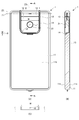
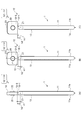
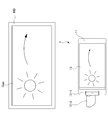
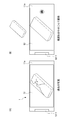
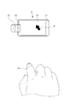
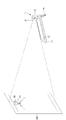
- FIG. 1 is a diagram showing an external configuration of an embodiment of an information processing terminal according to the present invention.
- FIG. 1A is a front view of the information processing terminal.
- FIG. 1B is a top view of the information processing terminal 1.
- FIG. 1C is a left side view of the information processing terminal.
- the information processing terminal 1 includes at least a display function and a digital camera function, and includes a main body part 11 and a connection part 12, which are connected to each other so as to be freely rotatable.
- the main body 11 is a first housing that is formed in a rectangular columnar shape having a planar shape and incorporates various substrates and the like. On a predetermined surface 11 a (hereinafter referred to as “front surface 11 a”) of the main body 11, a display unit 13 configured by a touch panel display or the like is disposed.
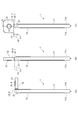
- FIG. 2 is a diagram showing an external configuration of the information processing terminal shown in FIG.
- FIG. 2A is a rear view of the information processing terminal.
- FIG. 2B is a cross-sectional view taken along line AA in FIG.
- FIG. 2C is a cross-sectional view of FIG. 2A as viewed from above.
- the back surface 11b of the main body 11 is one surface facing the front surface 11a described above with reference to FIG.
- the connecting portion 12 is formed in a substantially rectangular shape in plan view, and is rotatably disposed on one short side of the back surface 11 b of the main body portion 11.
- the connecting unit 12 includes a camera base 12-1 and a camera directing unit 12-2.
- a circular camera 21 is disposed in front of the camera directing unit 12-2 (the surface that can be seen in FIG. 2A). That is, the connecting portion 12 is a second housing that houses the camera 21.
- the camera 21 is an imaging unit that images a subject.
- a captured image including the subject imaged by the camera 21 is displayed on the display unit 13.
- the recess width W is the width of the recess for the camera unit.
- the rotation radius r2 is the longest rotation radius from the rotation axis (center) of the second hinge.
- the relationship between the recess width W and the rotation radius r2 is expressed by the following equation (1). W / 2> r2 (1)
- the camera base 12-1 is pivotally supported so that the entire connecting portion 12 can be rotated with respect to the main body 11 around the rotation axis Z1. More specifically, the camera base 12-1 is configured to be rotatable about the rotation axis Z1 while the end surface of the columnar outer shape is in sliding contact with the main body 11.
- the shaft support penetrates between both end surfaces.
- the shafts may be supported by both ends by inserting rotational shafts from both end surfaces, and may be supported by cantilever.
- the camera directing unit 12-2 on which the camera 21 is mounted is cantilevered with respect to the camera base 12-1 around a rotation axis Z3 disposed substantially orthogonal to the rotation axis Z1. It is pivotally supported.
- the arrangement direction of the camera 21 is approximately 90 degrees with respect to the rotation axis Z3. That is, the camera 21 can take a motion on a solid angle with respect to the main body portion 11 by two substantially orthogonal rotation axes that are the rotation axis Z1 and the rotation axis Z3.
- a connecting portion 12 is a portion that directly or indirectly connects the camera 21 so as to be rotatable relative to the main body portion 11 by a plurality of rotating shafts including the axis Z3.
- the connecting part 12 has one or more movable parts having a smaller volume than the main body part 11.
- a camera base 12-1 and a camera directing unit 12-2 are provided as such movable parts.
- the camera 21 serving as the imaging unit may be disposed on a predetermined surface of one or more movable units. In this example, the camera 21 is disposed in front of the camera directing unit 12-2 as described above.
- the angle formed by the direction of the rotation axis Z1 and the direction of the rotation axis Z3 is approximately 90 degrees.
- the information processing terminal 1 is further provided with a stand 14 so that the information processing terminal 1 can be placed on a desk or the like.
- the stand 14 is pivotally supported with respect to the main body 11 about the rotation axis Z2 as a rotation center. That is, the stand 14 is formed in a frame shape, and makes the information processing terminal 1 self-supporting and stable on a horizontal plane by forming a suitable arbitrary angle with the main body 11 by turning about the rotation axis Z2 (described later). See FIG.
- the planar shape substantially U-shape shown in the figure is an example, and it is needless to say that the planar shape may be substantially U-shaped. Furthermore, if it can be used on a vertical surface, which will be described later, it may have a planar hook shape.
- the space efficiency can be significantly improved as compared with the case where the stand 14 and the connecting portion 12 are separately disposed at positions, and the information processing terminal is wasted. It is possible to prevent the case 1 from becoming large. Alternatively, the internal substrate can be prevented from being divided unnecessarily. It should be noted that the connecting portion 12 and the stand 14 substantially share a center line with respect to both end surfaces with respect to the rotation axis as indicated by a line AA.
- the rotation axis Z1 is the rotation center of the connecting shaft between the main body 11 and the connecting portion 12.
- the rotation range of the rotation axis Z1 is approximately 180 degrees or more from the back surface 11b, and desirably exceeds 270 degrees.
- the rotation axis Z ⁇ b> 2 is the rotation center of the connection axis between the main body 11 and the stand 14. It is desirable that the rotation range of the rotation axis Z2 reaches 180 degrees from the back surface 11b. In particular, an arbitrary angle from the back surface 11b to 90 degrees is opposed to the self-weight moment of the information processing terminal 1 on the horizontal plane. A moderate rotation resistance is given so that it can be maintained. As a result, the user can place the information processing terminal 1 in a self-supporting and stable manner at a desired angular posture on a horizontal plane.
- part offset by the rotation axis Z2 side of the stand 14 may be provided, and the rotation center of the rotation axis Z1 and the rotation axis Z2 may be shared.
- the rotation axis Z3 is the rotation center of the connection shaft between the camera base 12-1 and the camera directing unit 12-2.
- the rotation axis Z3 is provided substantially orthogonal to the rotation axis Z1, and rotates on a substantially orthogonal plane around the rotation axis Z1. It is desirable that the rotation range of the rotation axis Z3 reaches 180 degrees each from the substantially orthogonal plane around the rotation axis Z1 around which the rotation axis Z3 rotates.
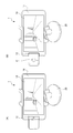
- FIG. 3 is a diagram illustrating a state where the connecting portion of the information processing terminal in FIG. 1 is rotated.
- the connecting portion 12 (more precisely, the camera base 12-1) of the information processing terminal 1 of FIG. 1 is in a state of being rotated 90 degrees about the rotation axis Z1.
- the connecting portion 12 (more precisely, the camera base 12-1) further rotates about the rotation axis Z1 from the state of FIG. 3A, and about the rotation axis Z1. It is in a state of being rotated 180 degrees.
- the connecting portion 12 (more precisely, the camera directing portion 12-2) is further rotated 90 degrees around the rotation axis Z3 from the state of FIG. 3B. .
- FIG. 3A the connecting portion 12 (more precisely, the camera base 12-1) of the information processing terminal 1 of FIG. 1 is in a state of being rotated 90 degrees about the rotation axis Z1.
- the connecting portion 12 (more precisely, the camera directing portion 12-2) is further rotated 90 degrees around the rotation axis Z3 from the state
- the distance h ⁇ b> 1 is from the rotation axis (center) of the first-axis hinge to the upper side surface of the main body 11 of the information processing terminal 1 (smartphone). This is the longest distance to the top surface of the terminal 1 (the one with the display unit 13) or the bottom surface of the information processing terminal 1 (the one without the display unit 13).
- the distance h2 is a distance from the rotation axis (center) of the first-axis hinge to the rotation section of the second-axis hinge.
- the relationship between the distance h1 and the distance h2 is a relationship represented by the following expression (2). h2> h1 (2)
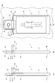
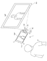
- FIG. 4 is a diagram illustrating a state in which the stand 14 of the information processing terminal 1 in FIG. 1 is rotated.
- FIG. 4A is the same state as FIG. 3B described above, and the stand 14 is not rotated and is housed in the main body 11.
- the stand 14 is further rotated about the rotation axis Z2 from the state of FIG. 4A, and is rotated 180 degrees about the rotation axis Z2.
- the relationship between the distance h1 and the distance h2 is the same as that in the above equation (2).
- the user turns the stand 14 180 degrees about the rotation axis Z2 so that the user can clip the stand 14 to the wall KB as shown in FIG. 4 (C).
- the information processing terminal 1 can be attached to the wall KB by applying to CL or the like.
- the optical axis direction of the camera 21 photographing direction of the subject
- the normal direction of the display unit 13 the direction in which the user views the display unit 13
- the user can easily take a picture of himself as a subject, that is, take a selfie shot (self-portrait) while viewing the camera viewpoint image (an image of himself / herself) by facing the wall KB. .
- the stand 14 is rotated with respect to the main body 11 by the rotation axis Z2, and the camera 21 (the connecting portion 12) is rotated by the two axes of the rotation axis Z1 and the rotation axis Z3. Part 11).
- the user can also use the information processing terminal 1 over the wall KB as shown in FIG. 4 when performing a selfie shot (self-taking) or the like, or use the information processing terminal 1 as shown in FIG. It can also be used by leaning on a table.
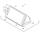
- FIG. 5 is a diagram illustrating a state where the information processing terminal 1 of FIG. 1 is used while standing on a table.
- FIG. 5A is a perspective view from the viewpoint of viewing the front surface 11a side where the display unit 13 is disposed.
- FIG. 5B is a perspective view showing a usage pattern on the desk of the information processing terminal of FIG. 1 as seen from the back surface 11b side on which the display unit 13 is arranged.
- the stand 14 in this embodiment is in a state of being rotated within 90 degrees about the rotation axis Z2 from the state of FIG.
- the rotation axis Z2 is given an appropriate rotation resistance so that an arbitrary angle of 90 degrees from the back surface 11b can be maintained against the self-weight moment of the information processing terminal 1 on the horizontal plane. As a result, the user can place the information processing terminal 1 in a self-supporting and stable manner at a desired angular posture on a horizontal plane.
- the information processing terminal 1 can turn the camera 21 toward the subject by rotating the rotation axis Z1 and the rotation axis Z3.
- the information processing terminal 1 can take a picture without holding the main body part 11 by using the shutter remote control function and the self-timer function together, it can solve various problems described later.
- a solution to this problem is to employ an information processing terminal 1 to which the present invention is applied. That is, since the information processing terminal 1 to which the present invention is applied has the stand 14, it can be fixed to a wall or a table as shown in FIGS. 4 and 5, and a selfie stick becomes unnecessary.
- the unnaturalness may be slightly reduced even if the selfie stick is used, but the unnaturalness may remain, and a pose where the white portion is desired (for example, a pose using both hands) may not be possible.
- a solution to this problem is to employ an information processing terminal 1 to which the present invention is applied. That is, the information processing terminal 1 to which the present invention is applied has a stand 14, a self-timer, and a shutter remote control function. Therefore, the information processing terminal 1 can be fixed to a wall or a table as shown in FIGS. Is no longer necessary.
- the information processing terminal 1 to which the present invention is applied has a stand 14 and a two-axis rotation mechanism of the camera, so that it can be fixed on a wall or a table as shown in FIGS. The hands of people other than the target are no longer needed.
- the information processing terminal 1 to which the present invention is applied has a stand 14 and a biaxial rotation mechanism of the camera, and can be fixed to a wall or a table as shown in FIGS. Is no longer necessary.
- the stand 14 is set up as shown in FIG. 9 and the connecting portion 12 is rotated by 180 degrees or more, so that the camera can be shot in a fixed state on the table, eliminating the need for a tripod. . In this case, it is not always necessary to stand the stand 14.
- the information processing terminal 1 to which the present invention is applied has a stand 14 and a camera rotation mechanism, so that it can be fixed to a wall or a table as shown in FIGS. It is no longer necessary to have.
- stand 14 as shown in FIG. 9 and rotate the connecting part 12 by 180 degrees or more to fix it on the desktop. You can shoot, so you don't have to hold your smartphone. In this case, it is not always necessary to stand the stand 14.
- the information processing terminal 1 to which the present invention has a stand 14 and a two-axis rotation mechanism of the camera, so that the rear camera is turned to the front by two-axis rotation as shown in FIGS. It is possible to wrap around and direct at any angle, and a front camera with a fixed angle becomes unnecessary.
- the stand 14 is raised as shown in FIG. 9 and the connecting portion 12 is rotated by 180 degrees or more, so that it can be taken in a fixed state on the table, so the angle is fixed.
- a front camera is not required. In this case, it is not always necessary to stand the stand 14.
- a solution to this problem is to employ an information processing terminal 1 to which the present invention is applied. That is, the information processing terminal 1 to which the present invention is applied utilizes the gap provided between the stand 14 and the connecting portion 12 by turning the connecting portion 12 and the stand 14 180 degrees.
- the information processing terminal 1 to which the present invention is applied utilizes the gap provided between the stand 14 and the connecting portion 12 by turning the connecting portion 12 and the stand 14 180 degrees.
- it since it can be suspended and supported on a flat surface using a projection or a pin-like member, it is suitable for use on a wall, and it is not necessary to separately provide a hook.
- the front camera is generally compared to the rear camera,
- A Low resolution
- B Low sensitivity (Cannot shoot without flash in dark scenes)
- C There is a fixed focus that is not autofocus.
- D There is an autofocus type, but the autofocus speed is slow
- e Low zoom magnification
- Many things are inferior in performance without a flashlight , I can not capture images with beautiful image quality.
- the rear camera and front camera have different performance, it is necessary to develop two cameras for one model.
- the usability such as navigating by voice is very bad.
- a solution to this problem is to employ an information processing terminal 1 to which the present invention is applied. That is, the information processing terminal 1 to which the present invention is applied can point the camera 21 as a high-performance camera in any direction with respect to the terminal body, and can freely view the camera viewpoint image while viewing the camera viewpoint image. Therefore, application software for taking a selfie shot without looking at the display unit 13 becomes unnecessary.
- the stand and the rotary camera which are the above solutions also require the respective axes for rotation on the main body side, and it is necessary to secure a space for the two axes. Will become bigger.
- the camera depending on how the camera is rotated, even if the camera of a smartphone that stands up on the stand rotates, the camera is often not suitable for the subject, which is often not a solution.
- it is possible to further increase the rotation axis so that the camera is directed to the subject it is often troublesome to always take a picture after the camera is pointed at the subject.
- a solution to this problem is to employ an information processing terminal 1 to which the present invention is applied. That is, the information processing terminal 1 to which the present invention is applied may use both the stand 14 and the rotation axis of the camera 21, so that the camera is always attached to the subject only by two-axis rotation as shown in FIGS. 4 and 5. 21 can be directed, and it is not necessary to increase the rotation axis.
- the display unit faces downward, and it is impossible to take a picture while viewing the camera viewpoint image.
- the orientation of the camera and the orientation of the display unit can be set separately, so that it is possible to shoot while viewing the camera viewpoint image.
- the vertical direction of the screen may change. However, if no effort is made, the vertical direction may be reversed. In such high-angle shots and low-angle shots, if the camera rotates in a fixed direction (for example, it rotates only clockwise from the normal position), it is difficult to shoot, so it can be rotated in both directions. It is desirable.
- a solution to this problem is to employ an information processing terminal 1 to which the present invention is applied. That is, the information processing terminal 1 to which the present invention is applied has the biaxial rotation mechanism of the stand 14 and the camera 21, so that the rear camera 21 is biaxially rotated as shown in FIGS. Therefore, it is possible to direct the light up and down freely, and a rear camera with a fixed angle becomes unnecessary.
- the angle of view wide angle, normal angle, narrow angle, etc.
- the distance to the subject is often short on the optical axis direction side of the front camera, so it is desired to shoot at a wide angle, but on the optical axis direction side of the rear camera, it is desired to shoot at a normal or narrow angle. Therefore, it is desirable that the angle of view automatically changes depending on the direction of the camera.
- a solution to this problem is to employ an information processing terminal 1 to which the present invention is applied. That is, since the information processing terminal 1 to which the present invention is applied has a shutter remote control function, when taking a selfie shot as shown in FIGS. 4 and 5, the shutter is not pressed without pressing the shutter button or the touch panel. Can be taken down, and it becomes unnecessary to hold the smartphone firmly.
- the information processing terminal 1 described above is installed on a desk or the like, the camera 21 is rotated toward the 10 people, When it is far away from the information processing terminal 1, the display unit 13 is too small to be seen, and it may be difficult to release the shutter because it is not possible to know whether everyone is in the frame of the camera viewpoint image or to understand each expression. is there. That is, there is a problem that the user wants to take a photograph while confirming the camera viewpoint image by some method.
- the solution to this problem is to employ the following technique.
- a screen sharing function that allows the camera viewpoint image to be transferred to another information processing terminal such as a smartphone or personal computer by wire or wireless to the information processing terminal 1 to which the present invention is applied, and enables operation. It is good to adopt the method of mounting. Thereby, it becomes possible to shoot a still image or a moving image from a remote position while sharing the camera viewpoint image of the information processing terminal 1 with other information processing terminals.
- the information processing terminals are directly connected to each other.
- the Internet the camera viewpoint image of the information processing terminal 1 placed at home is shared with the office personal computer, and the home screen is viewed while viewing the personal computer screen. It is also possible to take pictures of the remaining pets.
- a conventional digital camera or smartphone can also take a combined panoramic shot by moving the camera laterally. However, it is necessary to shoot while moving the smartphone or camera in various directions, and it is often impossible to synthesize beautifully.
- a solution to this problem is to employ an information processing terminal 1 to which the present invention is applied. That is, in the information processing terminal 1 to which the present invention is applied, the rotation about the rotation axes Z1 and Z3 of the camera 21 may be electric. Therefore, as shown in FIG. Therefore, it is not necessary to move the camera 21 laterally.
- gesture recognition cameras are very expensive and incur additional costs.
- a solution to this problem is to employ an information processing terminal 1 to which the present invention is applied.
- the information processing terminal 1 to which the present invention is applied is possible if the camera 21 facing the person has a high function (for example, gesture recognition of an exhibition), and a camera dedicated to gesture recognition is not necessary.
- the navigation can be used immediately without taking time to recognize the direction by a user interface in which an arrow is superimposed on an image actually captured by a camera.
- a user interface in which an arrow is superimposed on an image actually captured by a camera.
- the image of the rotated camera 21 can be displayed on the display unit 13 as one of the windows, and the presence of an obstacle can be transmitted by sound, screen or vibration, thereby avoiding danger. .
- a solution to this problem is to employ an information processing terminal 1 to which the present invention is applied. That is, the information processing terminal 1 to which the present invention is applied may be able to lock the rotation of the camera 21 at a specific angle. If the main body 11 is held and stabilized, the camera 21 is also stabilized.
- the information processing terminal 1 to which the present invention is applied can point the camera 21 in any direction with respect to the terminal body, and displays a camera viewpoint image on a part of the screen while displaying a navigation map. Since it can be displayed in a form like Picture in Picture, it can be used for other purposes at the same time while using a smartphone as a drive recorder. Therefore, a dedicated drive recorder becomes unnecessary.
- the installation in the car is installed so that it is a landscape screen, but the installation in a bicycle is installed so that it is a portrait screen, so the camera 21 can be rotated in two axes, so it can be used in a wide variety of ways. Is possible.
- a solution to this problem is to employ an information processing terminal 1 to which the present invention is applied.
- the information processing terminal 1 to which the present invention is applied is supposed to be applied to a stereo camera, and if there is a rotating camera 21, it can be solved, and it is not necessary to add a function to the front camera. .
- the connecting portion 12 is configured by two movable portions, that is, the camera base portion 12-1 and the camera directing portion 12-2.
- the connecting portion 12 is not particularly limited to the above-described embodiment, and the main body portion. It is sufficient to have one or more movable parts having a volume smaller than 11. In this case, it is sufficient that the camera 21 serving as the imaging unit is disposed on a predetermined surface of one or more movable units.
- a device having an arbitrary function can be mounted on an arbitrary number of arbitrary types of movable units (including a movable unit in which an imaging unit is arranged) among one or more movable units.
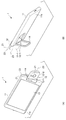
- FIG. 6 is a diagram showing an embodiment of the information processing terminal according to the present invention, in which a connecting portion of an embodiment different from FIG. 1 is rotated.
- the connecting portion 12 (more precisely, the camera base 12-1) of the information processing terminal 1 in FIG. 1 is in a state of being rotated 180 degrees around the rotation axis Z1.
- the connecting portion 12 (more precisely, the camera directing portion 12-2) is further centered on the rotation axis Z3 from the state of FIG. 6A (as viewed from the front surface 11a side of the main body portion 11). ) It is in a state rotated 90 degrees to the right.
- a circular camera 21 is arranged at the approximate center of the front of the camera directing unit 12-2 (the surface on the side visible in FIG. 6B).
- the connecting portion 12 (more precisely, the camera directing portion 12-2) is further centered on the rotation axis Z3 from the state of FIG. 6A (as viewed from the front surface 11a side of the main body portion 11). ) Turned 90 degrees to the left. As shown in FIG. 6C, a circular shape is formed at the approximate center of the back surface (the surface facing the front surface and seen in FIG. 6C) of the camera directing unit 12-2. A projector 22 is arranged. Further, as in FIG. 3, the relationship between the distance h1 and the distance h2 is the same as that in the above equation (2).
- the stand 14 is rotated with respect to the main body 11 by the rotation axis Z2, and the camera 21 (the connecting portion 12) is rotated by the two axes of the rotation axis Z1 and the rotation axis Z3. ) Rotates relative to the display unit 13 (main body unit 11). For this reason, the user can also lean and use the information processing terminal 1 on the table as shown in FIG. 7 when taking a selfie shot (self-taking) or the like.
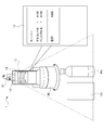
- FIG. 7 is a diagram illustrating a state in which the information processing terminal 1 of FIG. 6 is used while standing on a table.
- the camera 21 images the user U.
- the captured image of the camera 21, that is, the camera viewpoint image including the image Ug ⁇ b> 1 of the user U is displayed on the display unit 13.
- the camera directing unit 12-2 is provided with a projector 22 on the back surface facing the front surface on which the camera 21 is placed. Accordingly, the projector 22 can also project a captured image of the camera 21, that is, a camera viewpoint image including the image Ug2 of the user U on the screen Scr.
- the camera viewpoint image can be viewed by the user U through the display unit 13 and can also be viewed by another person (not shown) through the screen Scr.
- the image displayed on the display unit 13 and the image projected on the screen Scr by the projector 22 are not necessarily matched as in the example of FIG. 7, and may be different images.
- the image of the user U (camera viewpoint image of the camera 21) is displayed on one of the display unit 13 and the screen Scr, and the other party's caller is displayed on the other.
- An image may be displayed.
- the camera 21 and the projector 22 may be arranged on the same surface or on different surfaces, without being arranged at the positions where the connecting portions 12 face each other.
- the imaging direction of the camera 21 and the projection direction of the projector 22 are One will be restricted. Therefore, although not shown, a movable part different from the camera directing part 12-2 may be provided, and the projector 22 may be mounted on the movable part. As a result, the imaging direction of the camera 21 and the projection direction of the projector 22 can be independently directed in arbitrary directions.
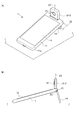
- FIG. 8 is a diagram showing an information processing terminal according to an embodiment of the present invention, which is used on a desk according to an embodiment different from FIGS. 1 and 6.
- the stand 23 is rotated about 50 degrees toward the back surface 11b around the rotation axis Z4, and is erected on the table.
- the axis Z3 is also rotated, and the camera 21 is in a state that enables selfie shots (self-taking).
- the stand 23 has substantially the same outer dimensions as the short side of the main body 11, and is integrated with the main body 11 in an morphological manner by setting the opening with the main body 11 to zero degrees. Configure the lower end.
- the rotation axis Z4 connects the main body 11 and the stand 23 at one corner of the main body 11 so as to be rotatable.
- the rotation axis Z4 has an axial direction substantially parallel to the long side of the main body 11.
- Appropriate rotation resistance is given so as to be independent and stable against the self-weight moment of the information processing terminal 1. Furthermore, you may provide the location which rotation can be stopped on the way in several places within the opening degree of 90 degree
- the rotation axis Z4 can rotate the stand 23 at least within 90 degrees on the back surface 11b side, and the opening degree of the main body 11 and the stand 23 can be set to zero degrees as described above.
- the rotation axis Z4 has an axial direction substantially parallel to the long side of the main body 11, so that the user can perform a selfie shot (self-taking) or the like as shown in FIG.
- the rotation angle of the rotation axis Z4 when the 1 is placed on the table and used in the horizontal position (landscape) coincides with the standing angle of the main body 11, and the adjustment of the angle is easy.
- the stand 23 can be brought into the use state shown in FIG. 8 by causing the main body 11 side while the information processing terminal 1 is placed on the table top from the table placed on the table. Further, by gently pressing the main body 11 side against the desk surface from this state, it is possible to shift to a more stable flat state without lifting the information processing terminal 1.
- the angle of the stand 23 can be finely adjusted, if the subject is above the front camera or the single-axis rotating camera, the camera can be perfectly pointed at the subject even if it is not a two-axis camera. It becomes possible.
- FIG. 9 is a diagram illustrating a state in which the information processing terminal of FIG.
- FIG. 9A is a perspective view showing a state in which the table is used in a vertical position (portrait) on a table.
- FIG. 9 (B) is a side view showing a state in which the computer is stood and used in a vertical position (portrait).
- the stand 14 is rotated about 90 degrees toward the back surface 11b around the rotation axis Z2, is erected on the table, and the rotation axis Z1 is also rotated.
- the camera 21 is in a state in which it can be selfie shot (self-portrait) in a vertical position (portrait).
- the receiving side can also be held vertically or horizontally depending on whether the communication partner is capturing vertically or horizontally. Can be changed.
- the other party of the communication is taking a picture in a vertical position, but the user cannot take a selfie while the information processing terminal 1 is erected in the vertical position, the user on the side of the information processing terminal 1 Must be held by hand, or the other party should be held vertically to force side-by-side shooting, or both must accept that each other's images are displayed on the display section as small or out of place. Disappear.
- the information processing terminal 1 of FIG. 1 includes the stand 14 and the rotation mechanism of the photographing unit, even if there is no fixture such as a projection or a thumbtack that can be supported by hanging around the appropriate wall surface. It is possible to take a self-portrait by standing in a vertical position (portrait) on the table. As a result, the burden of holding the information processing terminal 1 by hand in the vertical position (portrait) and camera shake during hand-held imaging, etc. It will be freed from various problems at once.
- a mechanism may be employed in which an “open button” for automatically rotating the rotation axis Z1 is provided at a position where the pressing operation is easy such as a side surface of the main body 11 and the connecting portion 12 is easily raised by the pressing operation. .
- the camera is fixed on a tripod and taken at regular intervals, but there is a problem that a lot of equipment such as a tripod is required.
- a lot of equipment such as a tripod is required.
- there is a demand to move the camera in accordance with the movement of the sun for example, instead of fixing the camera completely during time-lapse shooting.
- Such additional equipment is required, and the setting is also required separately from the camera.
- the information processing terminal 1 has a biaxial rotation mechanism as shown in FIGS.
- the camera 21 can be fixed and a time-lapse photo or video of the Sun Sun visible from the window MD can be taken without using additional fixing equipment such as a tripod.
- the information processing terminal 1 shown in FIG. 10 has a plurality of rotation shafts such as the rotation shafts Z1 to Z4 described above, it does not require additional equipment such as a dolly, and is similar to the Sun Sun. It is possible to take time-lapse photos and videos by presetting the camera to move according to the movement of the moving object at low speed.
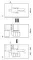
- the information processing terminal 1 can rotate the camera in the horizontal direction at an angle as shown in FIG. 11A, and the camera in the vertical direction at an angle as shown in FIG. It is possible to rotate.
- the information processing terminal 1 can cleanly or blur only the background of the captured image. is there.
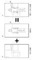
- an image including the object Obj is photographed as shown in FIG. 12A, and an image of only the background where the object Obj is not photographed before and after that is photographed as shown in FIG. Furthermore, by leaving only the difference between the image in FIG. 12A and the image in FIG. 12B, an image in which only the target Obj such as a product or a person is left can be created as shown in FIG. 12C. . Also, if an image in which only the object Obj is left as shown in FIG. 12C can be created, the image is combined with an image obtained by blurring the background only image as shown in FIG. As shown in FIG. 13F, an image with a beautifully blurred background can be created. It should be noted that even moving images can be displayed by moving in the same way as images, and can be used for video analysis of security cameras.
- the information processing terminal 1 can display past photo data translucently, or select a photo to be compared from the live view screen of the camera to be shot with one button. It can be displayed and automatically returned to the live view screen of the camera, or it can be returned to the live view screen of the camera with one action (pressing a button, pressing a button on the remote control, operating with a voice, etc.). It becomes possible to take comparative pictures.
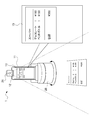
- the video displayed on the display unit 13 of the information processing terminal 1 is displayed on a large screen on a TV or projector wirelessly or by wire.
- the operation can be performed by a device that can be displayed on the screen such as the laser pointer LP.
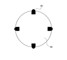
- three or more markers 24 can be displayed as part of the image on the screen Scr.
- the camera 21 of the information processing terminal 1 captures the cursor P of the laser pointer LP and three or more markers 24, so that the relative positional relationship between the image on the screen Scr and the cursor P can be obtained.
- the laser pointer LP may be provided with a button for enlarging / reducing the cursor P, and the enlargement / reduction button is integrated with the On / Off button of the cursor P. May be used. Changes such as changing the color or shape of the cursor may be added when the screen is enlarged or reduced.
- the number of cursors P is not limited to one, and a plurality of cursors P may be simultaneously determined. At the time of enlargement or reduction operation, it can be determined that the image is enlarged when the two points are separated, and the image is reduced when the two points are approached.
- the video on the display unit 13 that is output to a TV or a projector and the video on the screen that is displayed on the TV or the projector and the cursor P is also displayed in real time.
- the display unit 13 of the information processing terminal 1 and the screen output to the television receiver or projector do not necessarily match.
- the image captured by the camera 21 may be displayed on the display unit 13 of the information processing terminal 1, or nothing may be displayed for the purpose of lightening the processing.
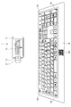
- the information processing terminal 1 shown in FIG. 16 uses the stand 14 to stand the information processing terminal 1, uses the rotation mechanism of the two-axis camera, fixes the camera 21, shoots the printed keyboard K, and A finger placed on K is photographed with a camera, and the position of the pressed finger can be detected.
- QR code registered trademark
- the button area of the keyboard K can be specified, the relative position of the button with the key pressed can be determined, and the finger position on the printed keyboard K can be determined.
- Character input is possible by pressing.
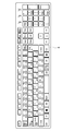
- the keyboard K having a general arrangement as shown in FIG. 17, but since the keyboard K can be manufactured by printing, it can be customized as much as desired without worrying about the sales volume. .
- buttons such as “Good morning.” “Ichiro Suzuki.” “Is.” “I ’ll get you”, I ’d like you to enter them in a unit of words instead of entering them one by one. Is also possible.
- game pads, musical instruments, video editing mixers, DJ mixers, musical instruments can also be printed. You can also input handwritten characters and illustrations by shooting with your camera.
- the camera 21 captures the movement of the finger Fn and the touch operation to the desk without directly operating the information processing terminal 1.
- the movement of the finger Fn is linked with the movement of the cursor P, and the operation can be performed in the same manner as when the touch pad of the personal computer is operated.
- the operation can be performed in the same manner as when moving with the jog dial of the mouse. It becomes possible to input handwritten characters in the same manner.
- the information processing terminal 1 includes a camera 21 that can be rotated about a plurality of rotation axes. Have. For this reason, the information processing terminal 1 is fixed by the navigation stand 25, and the camera 21 is used to shoot an image of the traveling direction of the car as an AR navigation or a drive recorder, and at the same time, the display unit 13 of the information processing terminal 1 is at an angle that is easy for the driver to see Can be directed.
- the camera 21 of the information processing terminal 1 normally captures the traveling direction as shown in FIG. As shown in FIG. 20 (B), the camera 21 rotates to photograph the driver's face and the like, and the driver's health condition can be checked.
- the current photographed image as shown in FIG. 21A is compared with the previous photograph as shown in FIG.
- the camera 21 and the rotary cradle 26 are adjusted by electric rotation so that the target Obj is at an appropriate position, or a guide for determining the pose is shown on the display unit 13 so that the same pose is obtained.
- a guide for example, a handwritten input can be displayed.
- the camera 21 always uses a rotation axis Z1 in a certain direction (for example, horizontal direction).
- the image displayed on the display unit 13 of the information processing terminal 1 can be kept constant by performing the electrical control using the G sensor data or the like so as to face.
- the book B is photographed by the camera 21 and is subjected to OCR, thereby recognizing text data and translating the information processing terminal 1. Can be displayed on the display unit 13.
- Each page of book B is photographed as a still image or a movie without pressing the shutter button, and translation is performed with the page being turned as a trigger.
- the page can be reloaded by voice or by sound.
- the information processing terminal 1 has a plurality of pivot axes in the connecting portion 12, the angle of the camera 21 can be changed without depending on the orientation of the display portion 13, so that this function is possible.
- the information processing terminal 1 on the rotary cradle 26, it is possible to earn a distance in the height direction, making it easy to take a picture, and rotating the rotary cradle 26 and each time of the information processing terminal 1.
- the direction of the camera 21 can be appropriately adjusted to the book B to be photographed, so that text data can be made with higher accuracy.
- the cash register used for accounting at a store is generally for business use, but it is very expensive, and it is read by a bar code reader of the product or detects an IC tag attached to the product. Therefore, a process of inputting product information to the cash register is required. In particular, in the case of bar code input, it may take time to align the position of the bar code, so it is necessary to master the bar code input operation. Individually managed bakers cannot put a barcode on the bread itself, so the store clerk manually inputs the product buttons at the cash register.
- the information processing terminal 1 that can rotate the camera 21 is used, or the information processing terminal 1 is placed on the rotary cradle 26.
- the orientation of the camera 21 automatically changes according to the position of the barcode, and for example, the barcode of the product to be purchased such as chocolate Ch or plastic bottle Pb is high. It becomes possible to read with accuracy.
- the shape of the product in advance, it is possible to know information such as the product name and price even for a product without a barcode such as bread.
- the information processing terminal 1 capable of rotating the camera 21 is placed on the rotary cradle 26 on the desk, thereby increasing
- the rotation of the rotary cradle 26 and the rotation of the information processing terminal 1 it is possible to earn a distance in the direction and operate each receipt on the desk (such as pressing a shutter). You can shoot automatically without having to.
- the rotary cradle 26 is not necessarily required.
- OCR optical character recognition
- the text data can be recognized and input. The user does not need to operate the information processing terminal 1 or the rotary cradle 26, and only has to concentrate on placing a receipt or a receipt. Receipts and receipts are easy to line up, especially on a desk-like plane.
- the information processing terminal of the present invention by fixing the top surface attachment to the rotary cradle 26, the product to be photographed is placed on the rotary cradle 26, While using the camera 21 of the information processing terminal 1 fixed by the stand 14, the rotation of the rotary cradle 26 is controlled from the information processing terminal 1, and 360 degree product photography is possible.
- a hanging attachment 27 is fixed to the rotary cradle 26, so that a thing is placed under the rotary cradle 26 with a hanger or the like. It becomes possible to hang.
- the rotation of the rotary cradle 26 is controlled from the information processing terminal 1 so that 360 degree product photography can be performed.
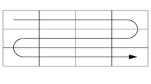
- a panoramic shot can be taken by moving the camera laterally even with a digital camera or smartphone, but it is often necessary to move the camera or smartphone smoothly and laterally, making it impossible to synthesize beautifully.
- you can move not only horizontally but also vertically you can synthesize even larger photos, but this is also not beautiful.
- the information processing terminal of the present invention by operating the camera 21 of the information processing terminal 1 by moving a plurality of rotation axes, as shown in FIG. Panorama shooting is possible, and larger photos can be taken. Furthermore, by placing the information processing terminal 1 on the rotary cradle 26, the photographing point is moved in the vertical direction using the rotation axis of the information processing terminal 1, and the horizontal rotation of the rotary cradle 26 is used. Thus, a wider area can be photographed than when only the rotation axis of the information processing terminal 1 is used. Since it can be shot electrically, it can be combined beautifully. If vertical and horizontal composition is possible, you can take larger photos. When scanning, if you decide the order of scanning in the way of a single stroke, there is no waste.
- the camera 21 of the information processing terminal 1 on the teacher Tc side is rotated, so that the desk is not pushed.
- the book B is automatically photographed, trapezoidally corrected, and upside down, and the book B and the teacher Tc are displayed on the display unit 13 of the student information processing terminal 1 as shown in FIG. It is also possible to display faces simultaneously. In that case, when the height from the desk to the camera is insufficient and it is not possible to photograph all the paper, it is preferable to use a stand or the like that can stand the information processing terminal 1 in the vertical direction.
- the rotary cradle 26 a distance in the height direction can be obtained, and the camera rotation function of the information processing terminal 1 is used for the vertical rotation of the camera, and the horizontal rotation of the rotary cradle 26 is adjusted. A wider area than the rotation of the information processing terminal 1 can be taken.
- the information processing terminal 1 capable of rotating the camera 21 is placed on the rotary cradle 26 on the desk, thereby rotating the information processing terminal 1.
- the camera 21 can be directed in all directions.
- the camera 21 is rotated after the position of the person is specified by the human sensation sensor 28 built in the rotary cradle 26 or the information processing terminal 1, so that the person can be moved without rotating. It becomes possible to shoot well. Even if there is no rotary cradle 26, if there is the camera 21 of the information processing terminal 1 that can rotate more than two axes, automatic photographing becomes possible.
- the position can be specified by calculating a subtle time difference when sound enters the microphone.
- a rotation mechanism By applying a rotation mechanism, an object can be determined and the camera can be automatically tracked. Shooting is not necessarily performed automatically, and may be performed with a voice or a gesture. If there is a person who does not want to take a picture by judging the person, it is possible to set so that the picture is automatically taken and no picture is taken. It is also possible to make a judgment by image processing such as not registering a person who does not want to take a picture with a camera in advance or making a cross mark by hand during shooting.
- the cradle In order to operate the functions built into the cradle, the cradle is not able to receive power from the smartphone because it is one of the main purposes to supply the smartphone with power for charging. Power supply such as a battery and an AC adapter is required, and the battery and the AC adapter must be carried for a very short time.
- the information processing terminal of the present invention it is automatically determined that power is not supplied to the rotary cradle 26, and power is supplied from the information processing terminal 1 to the rotary cradle 26.
- Functions such as the human sensor 28 attached to the rotary cradle 26 can be moved by the power source of the information processing terminal 1.
- an HDMI (registered trademark) terminal may be attached to enable video output, or a USB A terminal may be included, which may include various functions in the cradle. is there.
- a USB A terminal may be included, which may include various functions in the cradle.
- the in-camera of the personal computer is attached to the top or bottom of the display, and if you point the display, you will face the in-camera
- the face faces the connected monitor, so you do not always see the smartphone placed in the cradle, and the angle at which the in-camera faces depends on the angle of the cradle. Therefore, it is necessary to change the position and orientation of the cradle of the smartphone.
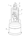
- the information processing terminal of the present invention when the information processing terminal 1 is placed on the rotary cradle 26 with the human sensor 28 as shown in FIG.
- the rotating cradle 26 and the rotation shaft of the information processing terminal 1 are driven so that the photographing target can be accommodated in the camera 21, and the photographing subject can be accommodated in the camera.
- the photographing target can be accommodated in the camera 21
- the photographing subject can be accommodated in the camera.
- it can it be used like an in-camera on a personal computer, but it can also be used for various purposes such as using the video of the camera 21 for face authentication, or using the human sensor 28 to turn off the monitor when no one is present. .
- Such a rotary cradle 26 can include, for example, a plurality of microphones, a plurality of speakers, a plurality of human sensors, a swivel function, a mobile battery, and the like.
- the information processing terminal mounted on the rotary cradle 26 is linked with information display, music playback, news playback, weather forecast, audio book, calendar, sports bulletin, traffic information, shopping, electricity, air conditioner, and curtain. It becomes possible to use it for various things.
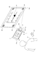
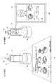
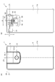
- FIG. 32 shows an external appearance and an internal configuration of an embodiment of the information processing terminal according to the present invention, which is different from FIG.
- FIG. 32A is a rear view of the information processing terminal.
- FIG. 32B is a cross-sectional view of FIG.
- the connecting unit 12 includes a camera base 12-1 and a camera directing unit 12-2.
- a circular camera 21 is arranged in front of the camera directing unit 12-2 (the surface that can be seen in FIG. 32A).
- the camera base 12-1 is pivotally supported so that the entire connecting portion 12 can be electrically rotated with respect to the main body 11 around the rotation axis Z1. That is, the camera base 12-1 is configured to be able to rotate around the rotation axis Z1 while sliding the end face of the columnar outer shape to the main body 11.
- a stepping motor 51, a biaxial hinge 53, a gear 54, and a gear 55 are provided inside the connecting portion 12 so as to enable automatic rotation about the rotation axis Z1 (see FIG. 32 (b)). That is, when the rotational driving force of the stepping motor 51 is transmitted to the biaxial hinge 53, the camera base 12-1 automatically rotates about the rotation axis Z1.
- the camera directing unit 12-2 on which the camera 21 is mounted is cantilevered with respect to the camera base 12-1 around a rotation axis Z3 disposed substantially orthogonal to the rotation axis Z1. It is pivotally supported.
- a stepping motor 52, a biaxial hinge 53, a gear 54, and a gear 56 are provided inside the connecting portion 12 so as to enable automatic rotation about the rotation axis Z3 (see FIG. 32 (b)). That is, when the rotational driving force of the stepping motor 52 is transmitted to the biaxial hinge 53 via the gear 54 and the gear 56, the camera directing unit 12-2 automatically rotates about the rotation axis Z3.
- the biaxial hinge 53 is not necessarily an integral biaxial hinge, and the hinge may be divided into two.
- the rotation on the rotation axis Z1 and the rotation axis X3 can be electrically performed with high accuracy and at high speed.
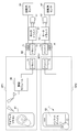
- FIG. 33 is a block diagram showing a configuration for realizing the rotation control on the rotation axis Z1 and the rotation axis Z3 when the stepping motor 51 and the stepping motor 52 of FIG. 32 are employed.
- the motor driver 61 of the stepping motor 51 and the motor driver 62 of the stepping motor 52 are realized in order to realize the rotation control on the rotation axis Z1 and the rotation axis Z3.
- a rotation angle sensor 63 of the stepping motor 51, a rotation angle sensor 64 of the stepping motor 52, an MCU (Micro Controller Unit) 65, and a wireless module 66 are provided.
- the MCU 65 includes a driver 71 serving as an interface with the wireless module 66, a driver 72 serving as an interface with the input device 82 of the information processing terminal 1, a driver 73 serving as an interface with the motor driver 61, and a motor driver 62.
- a driver 74 serving as an interface is provided.
- the MCU 65 is also provided with ADCs (Analog to Digital Converters) 75 and 76 in order to convert the analog detection signals of the rotation angle sensors 63 and 64 into digital signals.
- ADCs Analog to Digital Converters
- a user instruction OP1 using the wireless remote controller 81 or the like and an input device 82 such as a touch panel of the information processing terminal 1 are used as instructions for rotation on the rotation axis Z1 and the rotation axis Z3 (instruction for moving the camera 21).
- the user's instruction OP2 is performed.
- the instruction OP1 is input to the MCU 65 driver 71, and the instruction OP2 is input to the MCU 65 driver 72.
- the MCU 65 executes control for each of the motor drivers 61 and 62 via each of the drivers 73 and 74 based on the instruction by the instruction OP1 and the detection signals of the rotation angle sensors 63 and 64, respectively.
- the first is that the absolute position can be known (because it cannot be obtained by calculation if moved by the user's hand).
- the third point is that the direction of the camera 21 can be accurately calculated by combining the G sensor of the main body and the rotation angle sensors 63 and 64.
- an information processing terminal to which the present invention is applied can take various various embodiments.
- the information processing terminal to which the present invention is applied only needs to have the following configuration, and its embodiment is not particularly limited. That is, an information processing terminal to which the present invention is applied is An imaging unit (e.g., the camera of FIG. 2) that images a subject; A main body in which a display unit (for example, the display unit 13 in FIGS. 1 and 2) that displays a captured image including the subject imaged by the imaging unit is disposed on a predetermined surface (for example, the front surface 11a in FIGS. 1 and 2). Part (for example, main body part 11 in FIG. 1 and FIG. 2), A first rotation axis (for example, the rotation axis Z1 in FIG.
- a connecting portion (directly or indirectly) that allows the imaging unit to be rotated relative to the main body by a plurality of rotating shafts including a rotating shaft (for example, the rotating shaft Z3 in FIG. 2).
- a rotating shaft for example, the rotating shaft Z3 in FIG. 2.
- the connecting portion has one or more movable portions (for example, the camera base portion 12-1 and the camera directing portion 12-2 in FIG. 2) having a smaller volume than the main body portion,
- the imaging unit is disposed on a predetermined surface of a predetermined one of the one or more movable units (for example, the camera directing unit 12-2),
- An angle formed by the direction of the first rotation axis and the direction of the second rotation axis is approximately 90 degrees. Can be.
- main body part and the two or more movable parts are connected by a hinge having two or more axes.
- main body portion and the movable portion are connected by a flexible arm. Can be.
- the camera unit rotates around a rotation axis (for example, the rotation axis Z1) at a position perpendicular to the longitudinal direction of the main body, it stops before rotating to a position where it does not rotate any more. There is a place, Can be.
- a rotation axis for example, the rotation axis Z1
- the connecting portion rotates around a rotation axis (for example, the rotation axis Z1) at a position perpendicular to the longitudinal direction of the main body, the camera portion rotates greatly exceeding 180 degrees. Can be.
- the movable part for example, the camera directing part 12-2 to which the camera is attached is provided with an acceleration sensor for discriminating the vertical and horizontal directions, and the direction of the image on the display part is influenced by the value of the sensor.
- an acceleration sensor for discriminating the vertical and horizontal directions of the main body 11 is also provided on the main body 11 side, the orientation of the main body 11 and the orientation of the camera directing unit 12-2 are taken into consideration. Then, the camera viewpoint image is displayed.
- the angle between the main body part 11 and the camera directing part 12-2 is calculated by one or a plurality of sensors, and combined with the value of an acceleration sensor or the like mounted on the main body part 11, the camera directing part 12- Considering the direction of 2, it is also possible to adopt a method of displaying a camera viewpoint image.
- the stand has a rotation axis (for example, rotation axis Z2), and the stand rotates 180 degrees to a position parallel to the main body. Can be.
- a rotation axis for example, rotation axis Z2
- the main body part and the camera part can be separated from the beginning. Can be.
- the separated camera unit has one or more movable units, and the first rotation axis for changing the optical axis direction of the imaging unit of the camera and the second rotation direction different from the first rotation axis.
- the camera can be rotated by a plurality of rotation axes including a rotation axis, and an angle formed between the direction of the first rotation axis and the direction of the second rotation axis is approximately 90 degrees. Can be.
- the separated camera has an acceleration sensor for discriminating the vertical and horizontal directions, and the value of the sensor affects the orientation of the image on the display. Can be.
Landscapes
- Signal Processing (AREA)
- Engineering & Computer Science (AREA)
- Physics & Mathematics (AREA)
- General Physics & Mathematics (AREA)
- Multimedia (AREA)
- Studio Devices (AREA)
- Indication In Cameras, And Counting Of Exposures (AREA)
- Telephone Set Structure (AREA)
- Structure And Mechanism Of Cameras (AREA)
- Telephone Function (AREA)
- Camera Bodies And Camera Details Or Accessories (AREA)
- Viewfinders (AREA)
- Accessories Of Cameras (AREA)
Abstract
Description
この様な端末においては、高性能カメラを2個も使用すると、端末が高額となってしまうこと、カメラ並びにレンズを大きくしなければならずデザイン上に好ましくないこと、及び、通常は相手撮りをメインとして使用されることから、フロントカメラはサブカメラとして小型で安価な低性能のものが採用されていた。 Conventionally, in a mobile terminal with a camera such as a smartphone, in addition to a rear camera (camera dedicated to the other party) directed to the back side of the terminal display unit, a front camera (dedicated camera for self-portrait) directed to the display surface The thing which is equipped with separately was prevalent.
In such a terminal, if two high-performance cameras are used, the terminal becomes expensive, the camera and the lens must be enlarged, and it is not preferable in terms of design. Since it is used as a main, the front camera has been adopted as a sub-camera that is small, inexpensive, and has low performance.
例えば特許文献1には、イメージセンサ部が可動機構により撮影モードの選択に応じて回転し、この回転に合わせて使用するフィルタおよびレンズが自動的に切り替わる、という技術が開示されている。 However, there is a need to take a selfie with a high-performance camera while viewing the image actually captured by the camera (hereinafter referred to as “camera viewpoint image”) on the display unit. There was a self-portrait mode that shared the camera.
For example,
被写体を撮像する撮像部と、
前記撮像部により撮像される前記被写体を含む撮像画像を表示する表示部が所定の一面に配置された本体部と、
前記撮像部の光軸方向と前記表示部の法線方向とのなす角度を変化させる第1回転軸と、前記第1回転軸とは異なる方向の第2回転軸とを含む複数の回転軸により、前記撮像部を前記本体部に対して相対的に回動可能に、直接的又は間接的に連結する連結部と、
を備える。 In order to achieve the above object, an information processing terminal according to an aspect of the present invention is provided.
An imaging unit for imaging a subject;
A main body in which a display unit for displaying a captured image including the subject imaged by the imaging unit is disposed on a predetermined surface;
By a plurality of rotation axes including a first rotation axis that changes an angle formed by the optical axis direction of the imaging unit and the normal line direction of the display unit, and a second rotation axis that is different from the first rotation axis. A coupling unit that couples the imaging unit directly or indirectly to be rotatable relative to the main body unit;
Is provided.
前記連結部は、前記本体部より容積が小さい可動部を1以上有しており、
前記撮像部は、1以上の前記可動部のうち所定の1つの所定の面に配置され、
前記第1回転軸の方向と、前記第2回転軸の方向とのなす角度は、略90度である、
ようにすることができる。 Also,
The connecting part has one or more movable parts having a smaller volume than the main body part,
The imaging unit is disposed on a predetermined one predetermined surface of the one or more movable units,
An angle formed by the direction of the first rotation axis and the direction of the second rotation axis is approximately 90 degrees.
Can be.
情報処理端末1は、少なくとも表示機能とデジタルカメラ機能を備え、本体部11と連結部12より構成され、これらは回動自在に相互に接続されている。 FIG. 1 is a diagram showing an external configuration of an embodiment of an information processing terminal according to the present invention. FIG. 1A is a front view of the information processing terminal. FIG. 1B is a top view of the
The
連結部12は、平面形状略矩形に形成され、本体部11の背面11bの一方の短辺側に回動自在に配置される。連結部12は、カメラ基部12-1と、カメラ指向部12-2とを有している。カメラ指向部12-2の正面(図2(A)で見えている側の面)には円形状のカメラ21が配置されている。即ち、連結部12は、カメラ21を内蔵する第2筐体である。カメラ21は、被写体を撮像する撮像部である。カメラ21により撮像された被写体を含む撮像画像は、表示部13に表示される。ここで、図2(C)で示す様に、凹み幅Wは、カメラ部用の凹みの幅である。そして、回転半径r2は、2軸目のヒンジの回転軸(中心)から一番長い回転半径である。これにより、凹み幅Wと回転半径r2の関係は、以下の式(1)で示す関係となる。
W/2>r2・・・(1) The
The connecting
W / 2> r2 (1)
より具体的には、カメラ基部12-1は、柱形の外形のうちの端面を本体部11に摺接しながら、回動軸Z1を中心として回動し得るように構成される。 The camera base 12-1 is pivotally supported so that the entire connecting
More specifically, the camera base 12-1 is configured to be rotatable about the rotation axis Z1 while the end surface of the columnar outer shape is in sliding contact with the
カメラ21が搭載されるカメラ指向部12-2は、回動軸Z1に対し略直交方向に配置された回動軸Z3を回動中心としてカメラ基部12-1に対し回動可能に片持ちで軸支される。 It is preferable in terms of strength that the shaft support penetrates between both end surfaces. However, the shafts may be supported by both ends by inserting rotational shafts from both end surfaces, and may be supported by cantilever. .
The camera directing unit 12-2 on which the
つまり、カメラ21は、回動軸Z1と回動軸Z3という2つの略直交独立した回動軸により、本体部11に対して、立体角上でモーションを取ることが出来る。 Here, the arrangement direction of the
That is, the
連結部12は、本体部11より容積が小さい可動部を1以上有している。本例では、このような可動部として、カメラ基部12-1と、カメラ指向部12-2が設けられている。
撮像部たるカメラ21は、1以上の可動部のうち所定の1つの所定の面に配置されれば足りるが、本例では上述のようにカメラ指向部12-2の正面に配置されている。
そして、回動軸Z1の方向と、回動軸Z3の方向とのなす角度は、略90度である。 Thus, the rotation axis Z1 that changes the angle formed by the optical axis direction of the
The connecting
The
The angle formed by the direction of the rotation axis Z1 and the direction of the rotation axis Z3 is approximately 90 degrees.
スタンド14は、回動軸Z2を回動中心として本体部11に対して回動可能に軸支される。
即ち、スタンド14は、枠状に形成され、回動軸Z2を中心とする回動により本体部11と好適な任意の角度を成すことにより、水平面上で情報処理端末1を自立安定させる(後述する図5参照)。
なお、図示した平面形状略コの字状は一例であって、平面形状略U字状等であっても良いことは言うまでもない。
更には後述の垂直面上での使用が可能であれば、平面形状フック状等であっても良い。 The
The
That is, the
In addition, the planar shape substantially U-shape shown in the figure is an example, and it is needless to say that the planar shape may be substantially U-shaped.
Furthermore, if it can be used on a vertical surface, which will be described later, it may have a planar hook shape.
なお、連結部12とスタンド14は、回動軸に対する両端面についての中心線を、線A-Aのように略共有している。 By forming the
It should be noted that the connecting
回動軸Z1は、本体部11と連結部12を接続軸の回動中心である。
回動軸Z1の回動範囲は、背面11bから略180度以上までであって、270度を超えることが望ましい。 Further, the rotation axes Z1 to Z3 will be described below.
The rotation axis Z1 is the rotation center of the connecting shaft between the
The rotation range of the rotation axis Z1 is approximately 180 degrees or more from the
回動軸Z2の回動範囲は、背面11bから180度にまで達することが望ましく、特に背面11bから90度までの任意の角度を、水平面上での情報処理端末1の自重モーメントに対抗して維持できる様に、適度な回動抵抗が与えられている。
これによりユーザは、情報処理端末1を、水平面上で所望の角度姿勢で自立安定させて配置することができる。
なお、スタンド14の回動軸Z2側にオフセットさせる部位を設けて、回動軸Z1と回動軸Z2の回動中心を共有させても良い。 The rotation axis Z <b> 2 is the rotation center of the connection axis between the
It is desirable that the rotation range of the rotation axis Z2 reaches 180 degrees from the
As a result, the user can place the
In addition, the site | part offset by the rotation axis Z2 side of the
回動軸Z3は、回動軸Z1とは略直交して設けられ、回動軸Z1回りの略直交平面上を回動する。
回動軸Z3の回動範囲は、回動軸Z3が回動する回動軸Z1回りの略直交平面より左右180度ずつにまで達することが望ましい。 The rotation axis Z3 is the rotation center of the connection shaft between the camera base 12-1 and the camera directing unit 12-2.
The rotation axis Z3 is provided substantially orthogonal to the rotation axis Z1, and rotates on a substantially orthogonal plane around the rotation axis Z1.
It is desirable that the rotation range of the rotation axis Z3 reaches 180 degrees each from the substantially orthogonal plane around the rotation axis Z1 around which the rotation axis Z3 rotates.
図3(A)では、図1の情報処理端末1の連結部12(より正確にはカメラ基部12-1)は、回動軸Z1を中心に90度回動した状態となっている。
図3(B)では、連結部12(より正確にはカメラ基部12-1)は、図3(A)の状態からさらに回動軸Z1を中心に回動し、回動軸Z1を中心に180度回動した状態となっている。
図3(C)では、連結部12(より正確にはカメラ指向部12-2)は、図3(B)の状態からさらに回動軸Z3を中心に90度回動した状態となっている。
図3(A)乃至図3(C)で示す様に、距離h1は、1軸目のヒンジの回転軸(中心)から、情報処理端末1(スマートフォン)の本体部11の上側面、情報処理端末1の天面(表示部13がある方)、または、情報処理端末1の底面(表示部13がない方)までの一番長い距離である。また、距離h2は、1軸目のヒンジの回転軸(中心)から2軸目のヒンジの回転断面までの距離である。そして、距離h1と距離h2との関係は、以下の式(2)で示す関係となる。
h2>h1・・・(2) FIG. 3 is a diagram illustrating a state where the connecting portion of the information processing terminal in FIG. 1 is rotated.
In FIG. 3A, the connecting portion 12 (more precisely, the camera base 12-1) of the
In FIG. 3B, the connecting portion 12 (more precisely, the camera base 12-1) further rotates about the rotation axis Z1 from the state of FIG. 3A, and about the rotation axis Z1. It is in a state of being rotated 180 degrees.
In FIG. 3C, the connecting portion 12 (more precisely, the camera directing portion 12-2) is further rotated 90 degrees around the rotation axis Z3 from the state of FIG. 3B. .
As shown in FIG. 3A to FIG. 3C, the distance h <b> 1 is from the rotation axis (center) of the first-axis hinge to the upper side surface of the
h2> h1 (2)
図4(A)は、上述の図3(B)と同一の状態であり、スタンド14は回動しておらず、本体部11に収納されている。
図4(B)では、スタンド14は、図4(A)の状態からさらに回動軸Z2を中心に回動し、回動軸Z2を中心に180度回動した状態となっている。
また、図3と同様に、距離h1と距離h2の関係は、上記の式(2)と同様の関係である。 FIG. 4 is a diagram illustrating a state in which the
FIG. 4A is the same state as FIG. 3B described above, and the
In FIG. 4B, the
Further, as in FIG. 3, the relationship between the distance h1 and the distance h2 is the same as that in the above equation (2).
この図4(C)の状態では、カメラ21の光軸方向(被写体の撮影方向)及び表示部13の法線方向(ユーザが表示部13を見る方向)は、壁KBの表面に対する法線方向となっている。
したがって、ユーザは、壁KBに対向して位置することで、カメラ視点画像(自身が写る画像)をみながら、自身を被写体とした撮影、即ちセルフィーショット(自撮り)をすることが容易にできる。 As shown in FIG. 4 (B), the user turns the
In the state of FIG. 4C, the optical axis direction of the camera 21 (photographing direction of the subject) and the normal direction of the display unit 13 (the direction in which the user views the display unit 13) are normal to the surface of the wall KB. It has become.
Therefore, the user can easily take a picture of himself as a subject, that is, take a selfie shot (self-portrait) while viewing the camera viewpoint image (an image of himself / herself) by facing the wall KB. .
このため、ユーザは、セルフィーショット(自撮り)等をする際に、図4に示すように情報処理端末1を壁KBにかけて使用することもできるし、図5に示すように情報処理端末1を卓上に立て掛けて使用することもできる。 As described above, the
For this reason, the user can also use the
図5(A)は、表示部13が配置された正面11a側をみる視点による斜視図である。
図5(B)は、表示部13が配置された背面11b側をみる図1の情報処理端末の卓上での使用形態を示す斜視図である。本形態におけるスタンド14は、図4(A)の状態から回動軸Z2を中心に90度以内で回動した状態となっている。 FIG. 5 is a diagram illustrating a state where the
FIG. 5A is a perspective view from the viewpoint of viewing the
FIG. 5B is a perspective view showing a usage pattern on the desk of the information processing terminal of FIG. 1 as seen from the
これによりユーザは、情報処理端末1を、水平面上で所望の角度姿勢で自立安定させて配置することができる。 The rotation axis Z2 is given an appropriate rotation resistance so that an arbitrary angle of 90 degrees from the
As a result, the user can place the
この状態でも、情報処理端末1は、回動軸Z1及び回動軸Z3を回動させることにより、カメラ21を被写体に向けることが出来る。 When the user related to the
Even in this state, the
しかしながら、従来のスマートフォンでは、下記のような様々な課題があった。
本発明が適用される情報処理端末1を採用することで、これら様々な課題を解決できるという効果を奏することができる。 That is, selfie shots (self-photographing) using a front camera on a conventional smartphone are prevalent worldwide, particularly in Asia.
However, conventional smartphones have various problems as described below.
By adopting the
この課題の従来の解決方法としては、セルフィースティック(自撮り棒)を用いるとい方法がある。この方法では、自分の手の長さ以上に離れた距離から写真を撮ることもできるが、セルフィースティックの長さ以上に離れた距離からは撮れない。加えて、セルフィースティックを持ち歩く必要性があり、安全性の観点からセルフィースティックの使用を禁止する場所(テーマパークやスポーツ施設やコンサート会場や駅のホームなど)も出てきており、万能な解決方法ではない。
つまり、セルフィースティックを用いないで撮影したいという課題がある。この課題の解決方法は、本発明が適用される情報処理端末1を採用することである。即ち、本発明が適用される情報処理端末1は、スタンド14を有しているので、図4や図5に示すように壁や卓上に固定可能であり、セルフィースティックが不要になる。 For example, users using conventional smartphones cannot take pictures of themselves from a distance more than the length of their hands because they press the shutter with their hands. In other words, because there is a wide-angle limit, it may not be possible for everyone (family, lovers, friends, etc.) who wants to take a picture together, or it is impossible to take a full body picture of themselves.
As a conventional solution to this problem, there is a method using a selfie stick. With this method, you can take pictures from a distance that is longer than the length of your hand, but you cannot take pictures from a distance that is longer than the length of the selfie stick. In addition, there is a need to carry a selfie stick, and there are some places (theme parks, sports facilities, concert venues, station platforms, etc.) that prohibit the use of selfie sticks from the viewpoint of safety. is not.
That is, there is a problem that it is desired to take a picture without using a selfie stick. A solution to this problem is to employ an
これはセルフィースティックを使っても若干不自然さが緩和される場合もあるが、不自然さは残り、白分がとりたいポーズ(例えば、両手を使ったポーズなど)が出来ない場合がある。 In addition, as you extend your hand, you can only shoot with your hand holding the shutter extended, creating an unnatural pose.
In some cases, the unnaturalness may be slightly reduced even if the selfie stick is used, but the unnaturalness may remain, and a pose where the white portion is desired (for example, a pose using both hands) may not be possible.
係る場合は、仲間の一人が犠牲となって、撮影者となるが、撮影者は集合写真に入ることができない。
店舗で、パーティーなどを開く際には、店員に依頼して、集合写真を撮ってもらうことが多いが、店員を呼ぶ必要があり、面倒である。 In addition, when it comes to a larger number of selfies, it becomes a group photo rather than selfies, but not all people can fit in the camera, either with their own hands or selfie sticks.
In such a case, one of the fellows is sacrificed and becomes a photographer, but the photographer cannot enter the group photo.
When a party is held at a store, the store clerk is often asked to take a group photo, but it is necessary to call the store clerk and is troublesome.
加えて、縦長の画面で撮影したい場合は、図9のようにスタンド14を立て、連結部12を180度以上回動させることで、卓上に固定した状態で撮影できるので、三脚が不要になる。この場合、必ずしもスタンド14を立てる必要はない。 In other words, there is a problem of wanting to shoot without using a tripod. A solution to this problem is to employ an
In addition, when shooting on a vertically long screen, the
加えて、縦長の画面で自分の顔を撮影してビデオチャットをしたい場合は、図9のようにスタンド14を立て、連結部12を180度以上回動させることで、卓上に固定した状態で撮影できるので、スマートフォンを手に持つことが不要になる。この場合、必ずしもスタンド14を立てる必要はない。 In other words, there is a problem of wanting to video chat without holding a smartphone. A solution to this problem is to employ an
In addition, if you want to take a video chat by shooting your face on a vertically long screen, stand 14 as shown in FIG. 9 and rotate the connecting
加えて、縦長の画面で撮影したい場合は、図9のようにスタンド14を立て、連結部12を180度以上回動させることで、卓上に固定した状態で撮影できるので、角度が固定されたフロントカメラが不要になる。この場合、必ずしもスタンド14を立てる必要はない。 That is, there is a problem that it is desired to shoot without using a front camera with a fixed angle. A solution to this problem is to employ an
In addition, when shooting on a vertically long screen, the
この課題の解決策として、壁に情報処理端末をぶら下げて固定する方法もあるが、その為のフックをスマートフォンに用意する必要があり、それもスマートフォン本体にスペースが必要になる。 Even if a smartphone is equipped with a stand, it cannot be placed if there is no place to place it and there are only walls.
As a solution to this problem, there is a method of hanging and fixing the information processing terminal on the wall, but it is necessary to prepare a hook for that purpose in the smartphone, which also requires space in the smartphone body.
(ア)低解像度
(イ)低感度(暗いシーンではフラッシュなしでは撮影ができない)
(ウ)固定焦点で、オートフォーカスではない
(エ)オートフォーカスのものもあるが、オートフォーカスのスピードが遅い
(オ)低ズーム倍率
(カ)フラッシュライトがない
と、性能的に劣るものが多く、椅麗な画質で撮像できない。
加えて、リアカメラとフロントカメラは性能が異なる場合、1機種の為に、2つのカメラを開発する必要がある。
この課題の解決方法として、リアカメラで、セルフィーショットを撮るアプリがあるが、表示部が見えないので、声でナビゲートする等、使い勝手は非常に悪かった。 Also, the front camera is generally compared to the rear camera,
(A) Low resolution (B) Low sensitivity (Cannot shoot without flash in dark scenes)
(C) There is a fixed focus that is not autofocus. (D) There is an autofocus type, but the autofocus speed is slow (e) Low zoom magnification (f) Many things are inferior in performance without a flashlight , I can not capture images with beautiful image quality.
In addition, if the rear camera and front camera have different performance, it is necessary to develop two cameras for one model.
As a solution to this problem, there is an application that takes a selfie shot with a rear camera. However, since the display portion cannot be seen, the usability such as navigating by voice is very bad.
例えば、ハイアングルショットは、写真を撮る際に、被写体が人垣に固まれていたりするときに、人垣の上から撮影するようなときに必要となるが、カメラを被写体に向けると表示部が上を向いてしまい、カメラ視点画像を視認しながら撮影することができない。 Also, with conventional information processing terminals where the rear camera and front display unit are fixed to the main unit, high angle shots taken from a position higher than the eyes and low angle shots taken from a position lower than the waist are Since the direction and the direction of the display unit are opposite to each other, it is difficult to take a picture while viewing the display unit.
For example, high-angle shots are necessary when taking a picture, such as when the subject is stuck in a fence or when shooting from the top of the fence. Therefore, the user cannot take a picture while viewing the camera viewpoint image.
この課題の解決策として、カメラが回動すると、カメラの向きと表示部の向きを別々に設定できるので、カメラ視点画像を視認しながらの撮影が、可能になる。 Similarly, when the camera is pointed from a position lower than the waist to a subject that is higher than the camera, the display unit faces downward, and it is impossible to take a picture while viewing the camera viewpoint image.
As a solution to this problem, when the camera rotates, the orientation of the camera and the orientation of the display unit can be set separately, so that it is possible to shoot while viewing the camera viewpoint image.
このようなハイアングルショットやローアングルショットの際には、カメラの回転する方向が決まっている(正位置から時計回りにしか回転しないとか)と撮影がしにくい為、両方向に回動可能であることが望ましい。 At this time, if the camera is rotated, the vertical direction of the screen may change. However, if no effort is made, the vertical direction may be reversed.
In such high-angle shots and low-angle shots, if the camera rotates in a fixed direction (for example, it rotates only clockwise from the normal position), it is difficult to shoot, so it can be rotated in both directions. It is desirable.
カメラ21を回動させていると、どこかのタイミングで、撮影できる画角(広角か通常か狭角か等)を自動で切り替えられると望ましい。一般的にはフロントカメラの光軸方向側は、被写体までの距離が短い場合が多いので、広角で撮影したいが、リアカメラの光軸方向側は、通常や狭角で撮影したい。よって、カメラの向きによって、画角が自動で変わると望ましい。 That is, there is a problem that it is desired to shoot without using a rear camera with a fixed angle. A solution to this problem is to employ an
When the
この課題の解決策として、タイマー設定や、ジェスチャー認識や音声認識によるシャッター押下があるが、シャッターが下ろされるタイミングがわかりにくかったり、反応が悪かったりして、例えば、5人でジャンプした瞬間を撮りたいといった時には使いにくい。 Also, when taking a selfie shot, it is necessary to press the shutter button or touch panel to release the shutter, and the smartphone cannot be held firmly, and the unstable smartphone may be dropped.
Solutions to this problem include timer setting and shutter pressing by gesture recognition and voice recognition, but it is difficult to understand when the shutter is released or the reaction is bad. It is difficult to use when you want to.
つまり、カメラ視点画像を何らかの方法で確認しながら、撮影したいという課題がある。
この課題の解決方法は、次のような手法を採用することである。即ち、本発明が適用される情報処理端末1に対して、カメラ視点画像を別のスマートフォンやパーソナルコンピュータなどの情報処理端末に、有線、もしくは無線で転送し、操作も可能にする画面共有機能を搭載するという手法を採用するとよい。
これにより、情報処理端末1のカメラ視点画像を他の情報処理端末と共有しながら、離れた位置から静止画や動画の撮影をすることが可能になる。情報処理端末同士が直接繋がる場合もあれば、インターネット回線を使って、自宅に置いた情報処理端末1のカメラ視点画像をオフィスのパーソナルコンピュータと画面共有し、そのパーソナルコンピュータの画面を見ながら、自宅に残っているペットの撮影をしたりすることも可能である。 Here, even if there is a shutter remote control function, for example, when taking a group shot with 10 people, the
That is, there is a problem that the user wants to take a photograph while confirming the camera viewpoint image by some method.
The solution to this problem is to employ the following technique. In other words, a screen sharing function that allows the camera viewpoint image to be transferred to another information processing terminal such as a smartphone or personal computer by wire or wireless to the
Thereby, it becomes possible to shoot a still image or a moving image from a remote position while sharing the camera viewpoint image of the
しかし、スマートフォンやカメラを様々な方向に向けて横移動しながら撮影する必要があり、綺麗に合成できない場合が多い。 A conventional digital camera or smartphone can also take a combined panoramic shot by moving the camera laterally.
However, it is necessary to shoot while moving the smartphone or camera in various directions, and it is often impossible to synthesize beautifully.
かつ、ジェスチャー認識用のカメラは非常に高価であり、追加の費用が発生していた。 In addition, there have been attempts to use human gestures for device and game operations. However, cameras that recognize gestures must always face the subject, so a camera terminal and a game terminal are prepared separately. It was necessary to do it and was not able to process with one smartphone.
In addition, gesture recognition cameras are very expensive and incur additional costs.
この課題の解決策として、カメラを使ったARによるナビゲーションがある。 Also, traditionally, smartphones have pedestrian navigation software, but even when outdoors, it is not easy to know the direction you are facing, and you do not know the direction you should go. It takes time.
As a solution to this problem, there is navigation by AR using a camera.
ただし、本体部背面に直交する角度で固定されたカメラで撮影するためには、常にスマートフォン本体部を地面と垂直に持つ必要があり、その際の表示部は非常に見難い角度になったり、ずっと持つのに疲れたりする。 The navigation can be used immediately without taking time to recognize the direction by a user interface in which an arrow is superimposed on an image actually captured by a camera.
However, in order to shoot with a camera fixed at an angle orthogonal to the back of the main unit, it is necessary to always have the smartphone main unit perpendicular to the ground, and the display unit at that time becomes an angle that is very difficult to see, I'm tired of having it all the time.
これら2つの課題も、回動式のカメラがあれば、解決できる場合がある。
「歩きスマホ」時に、回動したカメラ21の映像を表示部13にウィンドウの一つとして表示したり、障害物の存在を、音や画面や振動で伝えることも可能になり、危険を回避できる。 “Walking smartphone”, the act of using a smartphone while walking outdoors, is also a social phenomenon, but since it is concentrated on the screen, it is hard to notice until it hits.
These two problems may be solved if there is a rotating camera.
At the time of “walking smartphone”, the image of the rotated
スマートフォンにアプリケーションソフトウェアをインストールすることで、ドライブレコーダー代わりにすることも可能であるが、あまり、広まっていない。
自動車の場合の理由として、車のダッシュボードの上に吸盤や両面テープなどでスマートフォン等を固定するホルダーを使って、ドライバーから表示部を見やすいようにスマートフォンを固定すると、そのスマートフォンのカメラの光軸方向は、撮影したい車前方や後方を向かず、ダッシュボードが写ってしまう。
つまり、ドライバーから見やすい位置かつ運転の妨げにならない位置にスマートフォンを置くと、ドライブレコーダーの役割を果たせない。一方、ドライブレコーダーとしての映像を優先すると、スマートフォンをドライバーから見にくい位置に設置しなければならない。そうすることによって、スマートフォンをドライブレコーダー兼ナビゲーションシステムとして利用したいなどの兼用用途を満たすことができなくなってしまう。自転車の場合も同様である。その為、スマートフォンをドライブレコーダーとして使うことがあまり広まっていないと考えられる。
つまり、スマートフォンをドライブレコーダーとして利用しながら、他の用途にも同時に使いたいという課題がある。
この課題の解決方法は、本発明が適用される情報処理端末1を採用することである。即ち、本発明が適用される情報処理端末1は、カメラ21を端末本体に対して自由な方向に向けることが可能であり、ナビゲーションの地図を表示しながら、画面の一部にカメラ視点画像をPicture in Pictureのような形で表示できるので、スマートフォンをドライブレコーダーとして利用しながら、他の用途にも同時に使うことができる。よって、専用のドライブレコーダーが不要になる。
なお、自動車への設置は、横長画面になるように設置するが、自転車への設置は、縦長画面になるように設置するなど、カメラ21が2軸で回転できるので、幅広い設置の仕方に対応が可能である。 Also, in recent years, in the event of an accident, a drive mounted on a car or bicycle that aims to contribute to objective verification of the accident by recording video data or data using GPS (Global Positioning System). Recorders are spreading rapidly.
It is possible to replace the drive recorder by installing application software on the smartphone, but it has not become widespread.
As a reason for automobiles, if a smartphone is fixed on the dashboard of a car with a suction cup or double-sided tape to fix the smartphone so that the driver can easily see the display, the optical axis of the smartphone's camera The direction does not point to the front or rear of the car you want to shoot, and the dashboard appears.
In other words, if you place your smartphone in a position that is easy for the driver to see and does not interfere with driving, you cannot play the role of a drive recorder. On the other hand, if priority is given to video as a drive recorder, the smartphone must be placed in a position that is difficult for the driver to see. By doing so, it becomes impossible to satisfy the combined use such as wanting to use the smartphone as a drive recorder / navigation system. The same applies to bicycles. For this reason, it seems that using a smartphone as a drive recorder is not widespread.
In other words, while using a smartphone as a drive recorder, there is a problem of wanting to use it for other purposes at the same time.
A solution to this problem is to employ an
In addition, the installation in the car is installed so that it is a landscape screen, but the installation in a bicycle is installed so that it is a portrait screen, so the
この場合、撮像部たるカメラ21は、1以上の可動部のうち所定の1つの所定の面に配置されれば足りる。
さらに、1以上の可動部のうち任意の個数の任意の種類の可動部(撮像部が配置された可動部含む)には、任意の機能を有するデバイスを搭載させることができる。 For example, in the above-described embodiment, the connecting
In this case, it is sufficient that the
Furthermore, a device having an arbitrary function can be mounted on an arbitrary number of arbitrary types of movable units (including a movable unit in which an imaging unit is arranged) among one or more movable units.
図6は、本発明の情報処理端末の一実施形態であって、図1とは異なる実施形態の連結部を回動させた様子を示す図である。 For example, as shown in FIG. 6, a
FIG. 6 is a diagram showing an embodiment of the information processing terminal according to the present invention, in which a connecting portion of an embodiment different from FIG. 1 is rotated.
図6(B)では、連結部12(より正確にはカメラ指向部12-2)は、図6(A)の状態からさらに回動軸Z3を中心に(本体部11の正面11a側からみて)右方に90度回動した状態となっている。図6(B)に示すように、カメラ指向部12-2の正面(図6(B)で見えている側の面)の略中央には円形状のカメラ21が配置されている。
図6(C)では、連結部12(より正確にはカメラ指向部12-2)は、図6(A)の状態からさらに回動軸Z3を中心に(本体部11の正面11a側からみて)左方に90度回動した状態となっている。図6(C)に示すように、カメラ指向部12-2の背面(正面とは対向する面であって、図6(C)で見えている側の面)の略中央には円形状のプロジェクタ22が配置されている。
また、図3と同様に、距離h1と距離h2の関係は、上記の式(2)と同様の関係である。 In FIG. 6A, the connecting portion 12 (more precisely, the camera base 12-1) of the
In FIG. 6B, the connecting portion 12 (more precisely, the camera directing portion 12-2) is further centered on the rotation axis Z3 from the state of FIG. 6A (as viewed from the
6C, the connecting portion 12 (more precisely, the camera directing portion 12-2) is further centered on the rotation axis Z3 from the state of FIG. 6A (as viewed from the
Further, as in FIG. 3, the relationship between the distance h1 and the distance h2 is the same as that in the above equation (2).
このため、ユーザは、セルフィーショット(自撮り)等をする際に、図7に示すように情報処理端末1を卓上に立て掛けて使用することもできる。 In the
For this reason, the user can also lean and use the
カメラ21は、ユーザUを撮像する。このカメラ21の撮像画像、即ちユーザUの像Ug1を含むカメラ視点画像は、表示部13に表示される。
さらに、図7に示すように、カメラ指向部12-2には、カメラ21が配置された正面と対向する背面にはプロジェクタ22が配置されている。これにより、プロジェクタ22は、カメラ21の撮像画像、即ちユーザUの像Ug2を含むカメラ視点画像をスクリーンScrに投影することもできる。
その結果、カメラ視点画像は、表示部13を通じてユーザUに視認されることができると共に、スクリーンScrを通じて図示せぬ他者に視認されることもできる。 FIG. 7 is a diagram illustrating a state in which the
The
Further, as shown in FIG. 7, the camera directing unit 12-2 is provided with a
As a result, the camera viewpoint image can be viewed by the user U through the
例えばテレビ電話として情報処理端末1を使用する場合であれば、表示部13とスクリーンScrとのうち一方に、ユーザUの画像(カメラ21のカメラ視点画像)を表示させ、他方に相手方通話者の画像を表示させてもよい。
また例えば、カメラ21とプロジェクタ22は、このように連結部12の対向する位置に配置しなくても、同じ面に配置してもよいし、異なる面に配置してもよい。 Note that the image displayed on the
For example, when the
Further, for example, the
図8は、本発明の情報処理端末の一実施形態であって、図1及び図6とは異なる実施形態の卓上での使用の様子を示す図である。 Further, for example, in the above-described embodiment, the
FIG. 8 is a diagram showing an information processing terminal according to an embodiment of the present invention, which is used on a desk according to an embodiment different from FIGS. 1 and 6.
スタンド23は、本体部11の短辺と略同外形寸法であり、本体部11との開度をゼロ度とすることで、本体部11と形態的に一体化し、情報処理端末1全体としての下端部を構成する。 In the
The
回動軸Z4は、軸方向が、本体部11の長辺に略平行であり。情報処理端末1の自重モーメントに対抗して自立安定する様、適度な回動抵抗が、与えられている。さらに、開度90度以内の数か所に、回動を途中で止められる箇所を、設けて良い。 The rotation axis Z4 connects the
The rotation axis Z4 has an axial direction substantially parallel to the long side of the
上述の通り、回動軸Z4は、軸方向が本体部11の長辺に略平行であるので、ユーザは、セルフィーショット(自撮り)等をする為に、図8に示すように情報処理端末1を卓上に立たせて横位置(ランドスケープ)で使用する場合の回動軸Z4の回動角が、本体部11の立設角と一致し、当該角度の調節が容易である。 The rotation axis Z4 can rotate the
As described above, the rotation axis Z4 has an axial direction substantially parallel to the long side of the
図9(A)は、卓上に縦位置(ポートレート)で立て掛けて使用している様子を示す斜視図である。
図9(B)は、卓上に縦位置(ポートレート)で立て掛けて使用している様子を示す側面図である。 FIG. 9 is a diagram illustrating a state in which the information processing terminal of FIG.
FIG. 9A is a perspective view showing a state in which the table is used in a vertical position (portrait) on a table.
FIG. 9 (B) is a side view showing a state in which the computer is stood and used in a vertical position (portrait).
例えばビデオチャットでの利用において、情報処理端末1を快適に使用する為、通信の相手方が縦持ちで撮像しているか、横持ちで撮像しているかに合わせて、受信側も縦持ち又は横持ちを替えることができる。 In the
For example, in order to use the
しかし、図1の情報処理端末1では、スタンド14及び撮影部の回動機構を備えるので、周囲に適当な壁面及びぶら下げて支持可能な突起物又は画鋲等の固定具が無い場合であっても、卓上に縦位置(ポートレート)で立設させて自撮りを行うことが出来、その結果、縦位置(ポートレート)で情報処理端末1を手で持ち続ける負担及び手持ち撮像時の手振れ等の諸問題から一挙に解放されることとなる。 If the other party of the communication is taking a picture in a vertical position, but the user cannot take a selfie while the
However, since the
この様にすることにより、突然のシャッターチャンスに備えて、カメラ21のアプリケーションプログラムを常時起動する必要が無く、有限貴重なバッテリー電源を浪費しなくて済む。
また、本体部11の側面等の押下操作容易な位置に、回動軸Z1を自動で回動させる「開くボタン」を設けて、押下操作により簡単に連結部12が起き上がる機構を採用してよい。 By the way, it is good also as a structure that the application program of the
In this way, it is not necessary to always start the application program of the
Further, a mechanism may be employed in which an “open button” for automatically rotating the rotation axis Z1 is provided at a position where the pressing operation is easy such as a side surface of the
しかしながら、本発明の情報処理端末の一実施形態によれば、図12および図13に示すように、情報処理端末1が、撮影画像の背景のみをキレイに消したりボカしたりすることが可能である。 When taking a picture of an object, for example, when you want to hide the background behind the object, for example, if you do not want to show a messy room or want a white background to attract people and products There is. Previously, the camera lens was used to create a blur, or two or more cameras were used to calculate the depth, but in the case of one ordinary smartphone camera or smartphone lens, It was difficult to blur or erase the background with high accuracy.
However, according to an embodiment of the information processing terminal of the present invention, as shown in FIGS. 12 and 13, the
情報処理端末1の表示部13とテレビジョン受像機やプロジェクタに出力する画面は必ずしも一致している必要はないことも付け加えておく。例えば、情報処理端末1の表示部13に、カメラ21で撮影している画像を表示しても良いし、処理を軽くするなどの目的で、敢えて何も表示しなくても良い。 However, according to one embodiment of the information processing terminal of the present invention, as shown in FIG. 15, the video displayed on the
It should be added that the
これを応用して、リモコンによるカメラ操作・回転を行ったり、ネットワーク越しの操作も可能になる。また、プライバシーを守るために、カメラの動きに制限をつけたり、撮影していることを示す目印をつけることもできる。例えば、ネットワーク越しの操作(カメラ21の向きを変える)を出来ないような設定を、操作される側の機器(カメラやスマートフォンなど)から行うことも可能である。撮影をしていることが分かるように、LED、表示画面、フラッシュライトを光らせたり、バイブや音を鳴らす、臭いを発する、撮影している画像をディスプレイに表示することも可能である。また、操作を行うためにパスワードの入力を必要とすることもできる。LEDを光らせたり、撮影中の画像の表示を行わない設定も操作される側、操作を受ける側どちらからも行えるし、行えないような設定もできる。 On the other hand, according to one embodiment of the information processing terminal of the present invention, as shown in FIG. 29A, the
By applying this, it is possible to operate and rotate the camera with a remote control, or to operate over a network. In addition, in order to protect the privacy, it is possible to restrict the movement of the camera or put a mark indicating that shooting is taking place. For example, it is also possible to perform a setting so that an operation over the network (changing the direction of the camera 21) cannot be performed from a device on the operated side (such as a camera or a smartphone). It is also possible to display on the display the image being photographed, which emits an LED, a display screen, a flashlight, vibrates or makes a sound, emits a smell, and so that it can be understood that the photographing is being performed. It is also possible to input a password to perform the operation. Settings that do not cause the LED to illuminate or display the image being shot can be performed from either the operated side or the operated side, and settings that cannot be performed can also be performed.
これにより、回転型クレードル26に搭載された情報処理端末は、情報表示、音楽再生、ニュースの再生、天気予報、オーディオブック、カレンダー、スポーツ速報、交通情報、買い物、電気、エアコン、カーテンとの連動等、各種各様なことに利用可能になる。 Such a
As a result, the information processing terminal mounted on the
連結部12の回動操作が電動化される場合、情報処理端末は、例えば図32のように構成される。
図32は、本発明の情報処理端末の一実施形態の外観及び内部の構成であって、図2等とは異なる構成を示している。図32(A)は、情報処理端末の背面図である。図32(B)は、図32(A)の断面図である。
連結部12は、図2と同様に、カメラ基部12-1と、カメラ指向部12-2とを有している。カメラ指向部12-2の正面(図32(A)で見えている側の面)には円形状のカメラ21が配置されている。 By the way, as described above, in the information processing terminal of the present invention, the
When the turning operation of the connecting
FIG. 32 shows an external appearance and an internal configuration of an embodiment of the information processing terminal according to the present invention, which is different from FIG. FIG. 32A is a rear view of the information processing terminal. FIG. 32B is a cross-sectional view of FIG.
Similarly to FIG. 2, the connecting
この回動軸Z1での自動的な回動を可能にすべく、ステッピングモーター51と、2軸ヒンジ53と、ギヤ54と、ギヤ55とが、連結部12の内部に設けられている(図32(b)参照)。
即ち、ステッピングモーター51の回転駆動力が、2軸ヒンジ53に伝達されることで、カメラ基部12-1は回動軸Z1を中心として自動的に回動する。 The camera base 12-1 is pivotally supported so that the entire connecting
A stepping
That is, when the rotational driving force of the stepping
この回動軸Z3での自動的な回動を可能にすべく、ステッピングモーター52と、2軸ヒンジ53と、ギヤ54と、ギヤ56とが、連結部12の内部に設けられている(図32(b)参照)。
即ち、ステッピングモーター52の回転駆動力が、ギヤ54及びギヤ56を介して、2軸ヒンジ53に伝達されることで、カメラ指向部12-2は回動軸Z3を中心として自動的に回動する。言うまでもなく、2軸ヒンジ53は必ずしも一体型の2軸ヒンジである必要はなく、ヒンジが2つに分割されていてもよい。 The camera directing unit 12-2 on which the
A stepping
That is, when the rotational driving force of the stepping
ステッピングモーター51、及びステッピングモーター52を採用した場合における、回動軸Z1及び回動軸Z3での回動の制御を実現するために、ステッピングモーター51のモータドライバ61及びステッピングモーター52のモータドライバ62、ステッピングモーター51の回転角センサ63及びステッピングモーター52の回転角センサ64、MCU(Micro Controller Unit)65、並びに無線モジュール66が設けられている。
なお、これらのブロック等は、説明の便宜上、情報処理端末1の外部に図示されているが、情報処理端末1に内蔵されてもよい。
MCU65には、無線モジュール66とのインターフェイスとなるドライバ71と、情報処理端末1のインプットデバイス82とのインターフェイスとなるドライバ72と、モータドライバ61とのインターフェイスとなるドライバ73と、モータドライバ62とのインターフェイスとなるドライバ74とが設けられている。MCU65にはまた、回転角センサ63,64の夫々のアナログの検出信号をデジタル信号に変換するために、ADC(Analog to Digital Converter)75,76の夫々が設けられている。 FIG. 33 is a block diagram showing a configuration for realizing the rotation control on the rotation axis Z1 and the rotation axis Z3 when the stepping
When the stepping
Note that these blocks and the like are illustrated outside the
The
指示OP1による指示はMCU65のドライバ71に、指示OP2による指示はMCU65のドライバ72に、夫々入力される。 As instructions for rotation on the rotation axis Z1 and the rotation axis Z3 (instruction for moving the camera 21), a user instruction OP1 using the wireless
The instruction OP1 is input to the
即ち、1つ目は、絶対位置を知る(ユーザの手で動かされたりすると計算で位置が出せないため)ことができる点である。2つ目は、可動範囲外まで動かないようにするためのFail Safeが可能になる点である。3つ目は、本体のGセンサと回転角センサ63,64とを組み合わせることで、カメラ21の向きを精度よく算出できる点である。 By adopting the two
That is, the first is that the absolute position can be known (because it cannot be obtained by calculation if moved by the user's hand). Second, it is possible to perform Fail Safe so as not to move outside the movable range. The third point is that the direction of the
即ち、本発明が適用される情報処理端末は、
被写体を撮像する撮像部(例えば図2のカメラ)と、
前記撮像部により撮像される前記被写体を含む撮像画像を表示する表示部(例えば図1や図2の表示部13)が所定の一面(例えば図1や図2の正面11a)に配置された本体部(例えば図1や図2の本体部11)と、
前記撮像部の光軸方向と前記表示部の法線方向とのなす角度を変化させる第1回転軸(例えば図2の回動軸Z1)と、前記第1回転軸とは異なる方向の第2回転軸(例えば図2の回動軸Z3)とを含む複数の回転軸により、前記撮像部を前記本体部に対して相対的に回動可能に、直接的又は間接的に連結する連結部(例えば図1や図2の連結部12)と、
を備える。 Thus, the information processing terminal to which the present invention is applied can take various various embodiments. In other words, the information processing terminal to which the present invention is applied only needs to have the following configuration, and its embodiment is not particularly limited.
That is, an information processing terminal to which the present invention is applied is
An imaging unit (e.g., the camera of FIG. 2) that images a subject;
A main body in which a display unit (for example, the
A first rotation axis (for example, the rotation axis Z1 in FIG. 2) that changes the angle formed by the optical axis direction of the imaging unit and the normal direction of the display unit, and a second direction different from the first rotation axis. A connecting portion (directly or indirectly) that allows the imaging unit to be rotated relative to the main body by a plurality of rotating shafts including a rotating shaft (for example, the rotating shaft Z3 in FIG. 2). For example, the connecting portion 12) of FIG. 1 and FIG.
Is provided.
前記撮像部は、1以上の前記可動部のうち所定の1つ(例えばカメラ指向部12-2)の所定の面に配置され、
前記第1回転軸の方向と、前記第2回転軸の方向とのなす角度は、略90度である、
ようにすることができる。 Further, the connecting portion has one or more movable portions (for example, the camera base portion 12-1 and the camera directing portion 12-2 in FIG. 2) having a smaller volume than the main body portion,
The imaging unit is disposed on a predetermined surface of a predetermined one of the one or more movable units (for example, the camera directing unit 12-2),
An angle formed by the direction of the first rotation axis and the direction of the second rotation axis is approximately 90 degrees.
Can be.
ようにすることができる。 Further, the main body part and the two or more movable parts are connected by a hinge having two or more axes.
Can be.
ようにすることができる。 Further, the main body portion and the movable portion are connected by a flexible arm.
Can be.
ようにすることができる。 Further, when the camera unit rotates around a rotation axis (for example, the rotation axis Z1) at a position perpendicular to the longitudinal direction of the main body, it stops before rotating to a position where it does not rotate any more. There is a place,
Can be.
ようにすることができる。 Further, when the connecting portion rotates around a rotation axis (for example, the rotation axis Z1) at a position perpendicular to the longitudinal direction of the main body, the camera portion rotates greatly exceeding 180 degrees.
Can be.
ようにすることができる。
具体的には例えば本体部11の上下左右方向を判別するための加速度センサなどが、本体部11側にも付いている場合は、本体部11の向きとカメラ指向部12-2の向きを勘案して、カメラ視点画像を表示する。
これ以外の手法として、本体部11とカメラ指向部12-2の角度を単数または複数のセンサにより計算し、本体部11に搭載されている加速度センサ等の値と組み合わせて、カメラ指向部12-2の向きを勘案して、カメラ視点画像を表示する手法を採用することもできる。 In addition, the movable part (for example, the camera directing part 12-2) to which the camera is attached is provided with an acceleration sensor for discriminating the vertical and horizontal directions, and the direction of the image on the display part is influenced by the value of the sensor. ,
Can be.
Specifically, for example, when an acceleration sensor for discriminating the vertical and horizontal directions of the
As another method, the angle between the
ようにすることができる。 In addition, there is a stand structure that can be fixed at different angles instead of placing the main body parallel or perpendicular to the ground surface.
Can be.
ようにすることができる。 In addition to this, the stand has a rotation axis (for example, rotation axis Z2), and the stand rotates 180 degrees to a position parallel to the main body.
Can be.
ようにすることができる。 Moreover, as a modification, the main body part and the camera part can be separated from the beginning.
Can be.
ようにすることができる。 In this case, the separated camera unit has one or more movable units, and the first rotation axis for changing the optical axis direction of the imaging unit of the camera and the second rotation direction different from the first rotation axis. The camera can be rotated by a plurality of rotation axes including a rotation axis, and an angle formed between the direction of the first rotation axis and the direction of the second rotation axis is approximately 90 degrees.
Can be.
ようにすることができる。 Moreover, even if the movable part is electrically powered,
Can be.
ようにすることができる。 In addition, the separated camera has an acceleration sensor for discriminating the vertical and horizontal directions, and the value of the sensor affects the orientation of the image on the display.
Can be.
ようにすることができる。 You can also use the shutter remote as a pen so that you can easily write and edit text after shooting.
Can be.
11・・・本体部
11a・・・正面
11b・・・背面
12・・・連結部
12-1・・・カメラ基部
12-2・・・カメラ指向部
13・・・表示部
14・・・スタンド
21・・・カメラ
22・・・プロジェクタ
23・・・スタンド
24・・・マーカー
25・・・ナビスタンド
26・・・回転型クレードル
27・・・ぶら下がりアタッチメント
28・・・人感センサ
51・・・ステッピングモーター
52・・・ステッピングモーター
53・・・2軸ヒンジ
54・・・ギヤ
55・・・ギヤ
61・・・モータドライバ
62・・・モータドライバ
63・・・回転角センサ
64・・・回転角センサ
65・・・MCU
66・・・無線モジュール
71・・・ドライバ
72・・・ドライバ
73・・・ドライバ
74・・・ドライバ
75・・・ADC
76・・・ADC
81・・・ワイヤレスリモコン
82・・・インプットデバイス
B・・・書物
CL・・・クリップ
Fn・・・指
K・・・キーボード
KB・・・壁
MD・・・窓
Obj・・・対象
P・・・ポインタ
QR・・・QRコード(登録商標)
Scr・・・スクリーン
Sun・・・太陽
Tc・・・教師
U・・・ユーザ
Ug1、Ug2・・・ユーザUの像
Z1、Z2、Z3、Z4・・・回動軸 DESCRIPTION OF
66 ...
76 ... ADC
81 ... Wireless
Scr ... Screen Sun ... Sun Tc ... Teacher U ... User Ug1, Ug2 ... Image of user U Z1, Z2, Z3, Z4 ... Rotation axis
Claims (2)
- 被写体を撮像する撮像部と、
前記撮像部により撮像される前記被写体を含む撮像画像を表示する表示部が所定の一面に配置された本体部と、
前記撮像部の光軸方向と前記表示部の法線方向とのなす角度を変化させる第1回転軸と、前記第1回転軸とは異なる方向の第2回転軸とを含む複数の回転軸により、前記撮像部を前記本体部に対して相対的に回動可能に、直接的又は間接的に連結する連結部と、
を備える情報処理端末。 An imaging unit for imaging a subject;
A main body in which a display unit for displaying a captured image including the subject imaged by the imaging unit is disposed on a predetermined surface;
By a plurality of rotation axes including a first rotation axis that changes an angle formed by the optical axis direction of the imaging unit and the normal line direction of the display unit, and a second rotation axis that is different from the first rotation axis. A coupling unit that couples the imaging unit directly or indirectly to be rotatable relative to the main body unit;
An information processing terminal comprising: - 前記連結部は、前記本体部より容積が小さい可動部を1以上有しており、
前記撮像部は、1以上の前記可動部のうち所定の1つの所定の面に配置され、
前記第1回転軸の方向と、前記第2回転軸の方向とのなす角度は、略90度である、
請求項1に記載の情報処理端末。 The connecting part has one or more movable parts having a smaller volume than the main body part,
The imaging unit is disposed on a predetermined one predetermined surface of the one or more movable units,
An angle formed by the direction of the first rotation axis and the direction of the second rotation axis is approximately 90 degrees.
The information processing terminal according to claim 1.
Priority Applications (11)
| Application Number | Priority Date | Filing Date | Title |
|---|---|---|---|
| US16/327,971 US20190260863A1 (en) | 2016-08-30 | 2017-08-30 | Information processing terminal |
| JP2018537372A JPWO2018043615A1 (en) | 2016-08-30 | 2017-08-30 | Information processing terminal |
| KR1020197007659A KR20190040263A (en) | 2016-08-30 | 2017-08-30 | Information processing terminal |
| CN201780053492.2A CN109891871B (en) | 2016-08-30 | 2017-08-30 | Information processing terminal |
| CA3040824A CA3040824A1 (en) | 2016-08-30 | 2017-08-30 | Information processing terminal |
| EP17846619.9A EP3509288B1 (en) | 2016-08-30 | 2017-08-30 | Information processing terminal |
| CN202210149791.9A CN114598761A (en) | 2016-08-30 | 2017-08-30 | Information processing terminal |
| US16/911,337 US11005982B2 (en) | 2016-08-30 | 2020-06-24 | Information processing terminal |
| US17/228,503 US11659074B2 (en) | 2016-08-30 | 2021-04-12 | Information processing terminal |
| US18/298,191 US20230283699A1 (en) | 2016-08-30 | 2023-04-10 | Information processing terminal |
| US18/623,840 US20240244128A1 (en) | 2016-08-30 | 2024-04-01 | Information processing terminal |
Applications Claiming Priority (2)
| Application Number | Priority Date | Filing Date | Title |
|---|---|---|---|
| JP2016168212 | 2016-08-30 | ||
| JP2016-168212 | 2016-08-30 |
Related Child Applications (2)
| Application Number | Title | Priority Date | Filing Date |
|---|---|---|---|
| US16/327,971 A-371-Of-International US20190260863A1 (en) | 2016-08-30 | 2017-08-30 | Information processing terminal |
| US16/911,337 Division US11005982B2 (en) | 2016-08-30 | 2020-06-24 | Information processing terminal |
Publications (1)
| Publication Number | Publication Date |
|---|---|
| WO2018043615A1 true WO2018043615A1 (en) | 2018-03-08 |
Family
ID=61300827
Family Applications (1)
| Application Number | Title | Priority Date | Filing Date |
|---|---|---|---|
| PCT/JP2017/031277 WO2018043615A1 (en) | 2016-08-30 | 2017-08-30 | Information processing terminal |
Country Status (7)
| Country | Link |
|---|---|
| US (5) | US20190260863A1 (en) |
| EP (1) | EP3509288B1 (en) |
| JP (3) | JPWO2018043615A1 (en) |
| KR (1) | KR20190040263A (en) |
| CN (2) | CN114598761A (en) |
| CA (1) | CA3040824A1 (en) |
| WO (1) | WO2018043615A1 (en) |
Cited By (2)
| Publication number | Priority date | Publication date | Assignee | Title |
|---|---|---|---|---|
| WO2020158955A1 (en) * | 2019-02-01 | 2020-08-06 | エックスリープ株式会社 | Information processing device |
| JP2020177900A (en) * | 2019-04-19 | 2020-10-29 | 上海美翰灯具有限公司 | Angle-adjustable selfie light supplement lamp |
Families Citing this family (21)
| Publication number | Priority date | Publication date | Assignee | Title |
|---|---|---|---|---|
| CN114598761A (en) * | 2016-08-30 | 2022-06-07 | 爱克斯立普有限公司 | Information processing terminal |
| CN106886255B (en) * | 2017-03-07 | 2023-08-29 | Oppo广东移动通信有限公司 | terminal |
| US20190327355A1 (en) * | 2017-11-07 | 2019-10-24 | Katrina Goff Candy | Hands free on call phone (foncph) |
| USD968390S1 (en) * | 2018-06-04 | 2022-11-01 | Compal Electronics, Inc. | Electronic device |
| USD866498S1 (en) * | 2018-09-28 | 2019-11-12 | Ben Mercer | Mobile device with an integrated hazardous condition detection system |
| CN112019660B (en) * | 2019-05-31 | 2021-07-30 | Oppo广东移动通信有限公司 | Control method of electronic device and electronic device |
| CN110505404A (en) * | 2019-08-21 | 2019-11-26 | Oppo(重庆)智能科技有限公司 | Photographic method and device based on mobile terminal |
| CN110602372B (en) * | 2019-10-14 | 2021-04-13 | 成都拓普森科技有限公司 | Mirror surface photographing and photographing equipment |
| CN110748754A (en) * | 2019-10-25 | 2020-02-04 | 安徽信息工程学院 | It is multi-functional from rapping bar |
| CN111405092A (en) * | 2020-03-19 | 2020-07-10 | 维沃移动通信有限公司 | Electronic device |
| KR20210118616A (en) | 2020-03-23 | 2021-10-01 | 삼성전자주식회사 | Display apparatus and the control method thereof |
| US11843853B2 (en) * | 2020-04-03 | 2023-12-12 | Canon Kabushiki Kaisha | Image pickup apparatus including display device capable of providing an appropriate display image and control method therefor |
| CN213370363U (en) * | 2020-07-06 | 2021-06-08 | 诚瑞光学(重庆)有限公司 | Wearable device |
| CN111867312B (en) * | 2020-07-31 | 2021-12-14 | 维沃移动通信有限公司 | Electronic device |
| US11240438B1 (en) * | 2021-05-10 | 2022-02-01 | Dell Products L.P. | Information handling system camera with automated tilt, pan and shutter functionality |
| US11910075B2 (en) * | 2021-11-12 | 2024-02-20 | Canon Kabushiki Kaisha | Imaging apparatus |
| CN113949801A (en) * | 2021-11-26 | 2022-01-18 | 维沃移动通信有限公司 | Shooting method and shooting device |
| US12069356B2 (en) | 2021-12-14 | 2024-08-20 | Dell Products L.P. | Display backplate to facilitate camera magnet attachment to a display panel |
| US20230188672A1 (en) * | 2021-12-14 | 2023-06-15 | Dell Products L.P. | Camera with magnet attachment to display panel and lightguide housing |
| US11985448B2 (en) * | 2021-12-14 | 2024-05-14 | Dell Products L.P. | Camera with magnet attachment to display panel |
| US20230188819A1 (en) * | 2021-12-14 | 2023-06-15 | Dell Products L.P. | Reversible chargeable camera and dock with rear wall privacy |
Citations (2)
| Publication number | Priority date | Publication date | Assignee | Title |
|---|---|---|---|---|
| JP2001136254A (en) * | 1999-11-10 | 2001-05-18 | Nec Corp | Portable radio communication apparatus |
| JP2008131555A (en) | 2006-11-24 | 2008-06-05 | Sony Ericsson Mobilecommunications Japan Inc | Mobile terminal |
Family Cites Families (39)
| Publication number | Priority date | Publication date | Assignee | Title |
|---|---|---|---|---|
| JP2000295504A (en) * | 1999-04-06 | 2000-10-20 | Canon Inc | Digital camera |
| JP2001051799A (en) * | 1999-05-28 | 2001-02-23 | Sony Corp | Display device and camera using the device |
| JP3751200B2 (en) | 2000-12-28 | 2006-03-01 | 株式会社ケンウッド | Foldable mobile phone |
| JP2003244301A (en) * | 2002-02-18 | 2003-08-29 | Nec Corp | Portable information terminal |
| JP2004023731A (en) * | 2002-06-20 | 2004-01-22 | Sharp Corp | Image pickup device and mobile information terminal equipped with the same |
| EP1586190B1 (en) * | 2003-01-23 | 2006-05-24 | BenQ Mobile GmbH & Co. oHG | Mobile telephone fitted with a pivotal camera |
| JP4288971B2 (en) | 2003-03-20 | 2009-07-01 | カシオ計算機株式会社 | Portable electronic device and display control method thereof |
| JP2004328279A (en) * | 2003-04-23 | 2004-11-18 | Kato Electrical Mach Co Ltd | Portable terminal machine |
| JP2005086252A (en) * | 2003-09-04 | 2005-03-31 | Nikon Corp | Portable terminal |
| JP4286735B2 (en) * | 2004-07-08 | 2009-07-01 | シャープ株式会社 | Portable device |
| KR100652570B1 (en) * | 2004-10-27 | 2006-12-07 | 엘지전자 주식회사 | Camera swivel apparatus for portable terminal |
| DE602005022932D1 (en) * | 2005-02-18 | 2010-09-23 | Nokia Corp | PORTABLE, ELECTRONIC DEVICE FOR IMAGE RECORDING |
| JP2006311196A (en) * | 2005-04-28 | 2006-11-09 | Sony Corp | Imaging apparatus and imaging method |
| TWI260906B (en) | 2005-05-17 | 2006-08-21 | Jin-Chiuan Huang | Lens turning device for mobile phone with camera function |
| KR100713433B1 (en) * | 2006-01-27 | 2007-05-04 | 삼성전자주식회사 | Self-cradling type mobile phone |
| TWI316167B (en) * | 2006-05-01 | 2009-10-21 | Quanta Comp Inc | Built-in webcam device |
| US7580625B2 (en) * | 2006-05-24 | 2009-08-25 | Nokia Corporation | Handheld electronic device |
| JP2008067228A (en) * | 2006-09-08 | 2008-03-21 | Toshiba Corp | Mobile terminal |
| JP4278675B2 (en) * | 2006-10-30 | 2009-06-17 | シャープ株式会社 | Portable information terminal |
| CN201019145Y (en) * | 2007-07-13 | 2008-02-13 | 林佐伟 | Mobile phone cover |
| KR101366859B1 (en) * | 2007-10-31 | 2014-02-21 | 엘지전자 주식회사 | Portable terminal |
| KR101356167B1 (en) * | 2007-11-02 | 2014-01-24 | 엘지전자 주식회사 | Portable terminal |
| TWI360383B (en) * | 2008-08-27 | 2012-03-11 | Pegatron Corp | Electronic apparatus |
| EP2178276B1 (en) * | 2008-10-20 | 2014-07-30 | LG Electronics Inc. | Adaptation of recorded or shown image according to the orientation of a mobile terminal |
| CN101754609B (en) * | 2008-12-08 | 2012-08-22 | 深圳富泰宏精密工业有限公司 | Portable electronic device |
| US20100304795A1 (en) * | 2009-05-28 | 2010-12-02 | Nokia Corporation | Multiple orientation apparatus |
| CN102103306B (en) * | 2009-12-16 | 2014-07-16 | 鸿富锦精密工业(深圳)有限公司 | Portable electronic device |
| JP2012186524A (en) * | 2011-03-03 | 2012-09-27 | Panasonic Corp | Portable terminal device with three dimensional camera |
| JP2014036434A (en) * | 2012-08-10 | 2014-02-24 | Panasonic Corp | Portable electronic device |
| US9615053B2 (en) * | 2014-01-10 | 2017-04-04 | Revolve Robotics, Inc. | Systems and methods for controlling robotic stands during videoconference operation |
| JP2015145961A (en) * | 2014-02-03 | 2015-08-13 | ソニー株式会社 | Imaging apparatus |
| JP6406966B2 (en) * | 2014-10-07 | 2018-10-17 | オリンパス株式会社 | IMAGING DEVICE, IMAGING DEVICE CONTROL METHOD, IMAGING DEVICE CONTROL PROGRAM |
| CN104333623B (en) * | 2014-11-06 | 2017-07-28 | 广东欧珀移动通信有限公司 | Terminal device |
| US9557775B2 (en) * | 2014-11-21 | 2017-01-31 | Google Inc. | Detecting an operating mode of a computing device using accelerometers |
| CN104539830A (en) * | 2014-12-16 | 2015-04-22 | 广东欧珀移动通信有限公司 | Camera shooting device capable of rotating by full angles |
| KR102332768B1 (en) * | 2015-02-16 | 2021-11-30 | 삼성전자주식회사 | Camera device and electronic device therefof |
| CN105988519A (en) * | 2015-02-16 | 2016-10-05 | 联想(北京)有限公司 | Electronic device |
| KR20160133328A (en) * | 2015-05-12 | 2016-11-22 | 삼성전자주식회사 | Remote control method and device using wearable device |
| CN114598761A (en) * | 2016-08-30 | 2022-06-07 | 爱克斯立普有限公司 | Information processing terminal |
-
2017
- 2017-08-30 CN CN202210149791.9A patent/CN114598761A/en active Pending
- 2017-08-30 JP JP2018537372A patent/JPWO2018043615A1/en active Pending
- 2017-08-30 CA CA3040824A patent/CA3040824A1/en not_active Abandoned
- 2017-08-30 EP EP17846619.9A patent/EP3509288B1/en active Active
- 2017-08-30 KR KR1020197007659A patent/KR20190040263A/en unknown
- 2017-08-30 CN CN201780053492.2A patent/CN109891871B/en active Active
- 2017-08-30 WO PCT/JP2017/031277 patent/WO2018043615A1/en unknown
- 2017-08-30 US US16/327,971 patent/US20190260863A1/en not_active Abandoned
-
2020
- 2020-05-25 JP JP2020090719A patent/JP7184375B2/en active Active
- 2020-06-24 US US16/911,337 patent/US11005982B2/en active Active
-
2021
- 2021-04-12 US US17/228,503 patent/US11659074B2/en active Active
-
2022
- 2022-11-16 JP JP2022183548A patent/JP2023022110A/en active Pending
-
2023
- 2023-04-10 US US18/298,191 patent/US20230283699A1/en not_active Abandoned
-
2024
- 2024-04-01 US US18/623,840 patent/US20240244128A1/en active Pending
Patent Citations (2)
| Publication number | Priority date | Publication date | Assignee | Title |
|---|---|---|---|---|
| JP2001136254A (en) * | 1999-11-10 | 2001-05-18 | Nec Corp | Portable radio communication apparatus |
| JP2008131555A (en) | 2006-11-24 | 2008-06-05 | Sony Ericsson Mobilecommunications Japan Inc | Mobile terminal |
Cited By (4)
| Publication number | Priority date | Publication date | Assignee | Title |
|---|---|---|---|---|
| WO2020158955A1 (en) * | 2019-02-01 | 2020-08-06 | エックスリープ株式会社 | Information processing device |
| JP2021184095A (en) * | 2019-02-01 | 2021-12-02 | エックスリープ株式会社 | Information processing device |
| JPWO2020158955A1 (en) * | 2019-02-01 | 2021-12-02 | エックスリープ株式会社 | Information processing equipment |
| JP2020177900A (en) * | 2019-04-19 | 2020-10-29 | 上海美翰灯具有限公司 | Angle-adjustable selfie light supplement lamp |
Also Published As
| Publication number | Publication date |
|---|---|
| CN114598761A (en) | 2022-06-07 |
| JP2023022110A (en) | 2023-02-14 |
| JP2020162130A (en) | 2020-10-01 |
| JPWO2018043615A1 (en) | 2019-08-15 |
| CN109891871B (en) | 2022-03-01 |
| US20190260863A1 (en) | 2019-08-22 |
| CN109891871A (en) | 2019-06-14 |
| US20210234949A1 (en) | 2021-07-29 |
| US11005982B2 (en) | 2021-05-11 |
| EP3509288B1 (en) | 2024-03-13 |
| US11659074B2 (en) | 2023-05-23 |
| EP3509288A1 (en) | 2019-07-10 |
| JP7184375B2 (en) | 2022-12-06 |
| US20240244128A1 (en) | 2024-07-18 |
| US20200344340A1 (en) | 2020-10-29 |
| CA3040824A1 (en) | 2018-03-08 |
| EP3509288A4 (en) | 2020-04-15 |
| US20230283699A1 (en) | 2023-09-07 |
| KR20190040263A (en) | 2019-04-17 |
Similar Documents
| Publication | Publication Date | Title |
|---|---|---|
| JP7184375B2 (en) | Information processing terminal | |
| US10831093B1 (en) | Focus control for a plurality of cameras in a smartphone | |
| US10331024B2 (en) | Mobile and portable screen to view an image recorded by a camera | |
| US9332208B2 (en) | Imaging apparatus having a projector with automatic photography activation based on superimposition | |
| CN100461212C (en) | Display control device, display control method, program, and portable apparatus | |
| TW201537977A (en) | Panoramic scene capturing and browsing mobile device, system and method | |
| JP2013519910A (en) | Accessories for personal communication devices | |
| US10261408B2 (en) | Mobile and portable camera platform for tracking an object | |
| KR20150141391A (en) | Mobile terminal | |
| CN108983971A (en) | Labeling method and device based on augmented reality | |
| JP2005010512A (en) | Autonomous photographing device | |
| WO2013136602A1 (en) | Imaging device with projector and imaging control method therefor | |
| WO2020158955A1 (en) | Information processing device | |
| TW201203129A (en) | Image pickup system | |
| JP3212469U (en) | Vehicle shooting system | |
| JP2020162149A (en) | Vehicle photographing system | |
| CN205946041U (en) | A mobile terminal for taking VR image and VR image imaging system thereof | |
| JP7146944B2 (en) | Display device | |
| CN108494896A (en) | Projection terminal, optical projection system and projecting method | |
| WO2016073993A1 (en) | Camera accessory for use with a mobile device | |
| TW201738649A (en) | Corresponding method between panorama video and message and system thereof having cloud software calculator to obtain an angle value and a first time point from the cloud database, and calculate and search a picture of panorama video corresponding to the message | |
| KR20160149945A (en) | Mobile terminal | |
| WO2018120231A1 (en) | Smart glasses |
Legal Events
| Date | Code | Title | Description |
|---|---|---|---|
| 121 | Ep: the epo has been informed by wipo that ep was designated in this application |
Ref document number: 17846619 Country of ref document: EP Kind code of ref document: A1 |
|
| ENP | Entry into the national phase |
Ref document number: 2018537372 Country of ref document: JP Kind code of ref document: A |
|
| NENP | Non-entry into the national phase |
Ref country code: DE |
|
| ENP | Entry into the national phase |
Ref document number: 20197007659 Country of ref document: KR Kind code of ref document: A |
|
| ENP | Entry into the national phase |
Ref document number: 2017846619 Country of ref document: EP Effective date: 20190401 |
|
| ENP | Entry into the national phase |
Ref document number: 3040824 Country of ref document: CA |