CN114598761A - Information processing terminal - Google Patents
Information processing terminal Download PDFInfo
- Publication number
- CN114598761A CN114598761A CN202210149791.9A CN202210149791A CN114598761A CN 114598761 A CN114598761 A CN 114598761A CN 202210149791 A CN202210149791 A CN 202210149791A CN 114598761 A CN114598761 A CN 114598761A
- Authority
- CN
- China
- Prior art keywords
- camera
- information processing
- processing terminal
- rotation axis
- main body
- Prior art date
- Legal status (The legal status is an assumption and is not a legal conclusion. Google has not performed a legal analysis and makes no representation as to the accuracy of the status listed.)
- Pending
Links
Images


Classifications
-
- H—ELECTRICITY
- H04—ELECTRIC COMMUNICATION TECHNIQUE
- H04M—TELEPHONIC COMMUNICATION
- H04M1/00—Substation equipment, e.g. for use by subscribers
- H04M1/02—Constructional features of telephone sets
- H04M1/0202—Portable telephone sets, e.g. cordless phones, mobile phones or bar type handsets
- H04M1/026—Details of the structure or mounting of specific components
- H04M1/0264—Details of the structure or mounting of specific components for a camera module assembly
-
- H—ELECTRICITY
- H04—ELECTRIC COMMUNICATION TECHNIQUE
- H04N—PICTORIAL COMMUNICATION, e.g. TELEVISION
- H04N23/00—Cameras or camera modules comprising electronic image sensors; Control thereof
- H04N23/58—Means for changing the camera field of view without moving the camera body, e.g. nutating or panning of optics or image sensors
-
- G—PHYSICS
- G03—PHOTOGRAPHY; CINEMATOGRAPHY; ANALOGOUS TECHNIQUES USING WAVES OTHER THAN OPTICAL WAVES; ELECTROGRAPHY; HOLOGRAPHY
- G03B—APPARATUS OR ARRANGEMENTS FOR TAKING PHOTOGRAPHS OR FOR PROJECTING OR VIEWING THEM; APPARATUS OR ARRANGEMENTS EMPLOYING ANALOGOUS TECHNIQUES USING WAVES OTHER THAN OPTICAL WAVES; ACCESSORIES THEREFOR
- G03B15/00—Special procedures for taking photographs; Apparatus therefor
-
- G—PHYSICS
- G03—PHOTOGRAPHY; CINEMATOGRAPHY; ANALOGOUS TECHNIQUES USING WAVES OTHER THAN OPTICAL WAVES; ELECTROGRAPHY; HOLOGRAPHY
- G03B—APPARATUS OR ARRANGEMENTS FOR TAKING PHOTOGRAPHS OR FOR PROJECTING OR VIEWING THEM; APPARATUS OR ARRANGEMENTS EMPLOYING ANALOGOUS TECHNIQUES USING WAVES OTHER THAN OPTICAL WAVES; ACCESSORIES THEREFOR
- G03B17/00—Details of cameras or camera bodies; Accessories therefor
- G03B17/02—Bodies
- G03B17/04—Bodies collapsible, foldable or extensible, e.g. book type
-
- G—PHYSICS
- G03—PHOTOGRAPHY; CINEMATOGRAPHY; ANALOGOUS TECHNIQUES USING WAVES OTHER THAN OPTICAL WAVES; ELECTROGRAPHY; HOLOGRAPHY
- G03B—APPARATUS OR ARRANGEMENTS FOR TAKING PHOTOGRAPHS OR FOR PROJECTING OR VIEWING THEM; APPARATUS OR ARRANGEMENTS EMPLOYING ANALOGOUS TECHNIQUES USING WAVES OTHER THAN OPTICAL WAVES; ACCESSORIES THEREFOR
- G03B30/00—Camera modules comprising integrated lens units and imaging units, specially adapted for being embedded in other devices, e.g. mobile phones or vehicles
-
- H—ELECTRICITY
- H04—ELECTRIC COMMUNICATION TECHNIQUE
- H04M—TELEPHONIC COMMUNICATION
- H04M1/00—Substation equipment, e.g. for use by subscribers
- H04M1/02—Constructional features of telephone sets
- H04M1/0202—Portable telephone sets, e.g. cordless phones, mobile phones or bar type handsets
- H04M1/026—Details of the structure or mounting of specific components
- H04M1/0266—Details of the structure or mounting of specific components for a display module assembly
-
- H—ELECTRICITY
- H04—ELECTRIC COMMUNICATION TECHNIQUE
- H04M—TELEPHONIC COMMUNICATION
- H04M1/00—Substation equipment, e.g. for use by subscribers
- H04M1/02—Constructional features of telephone sets
- H04M1/0202—Portable telephone sets, e.g. cordless phones, mobile phones or bar type handsets
- H04M1/026—Details of the structure or mounting of specific components
- H04M1/0272—Details of the structure or mounting of specific components for a projector or beamer module assembly
-
- H—ELECTRICITY
- H04—ELECTRIC COMMUNICATION TECHNIQUE
- H04M—TELEPHONIC COMMUNICATION
- H04M1/00—Substation equipment, e.g. for use by subscribers
- H04M1/02—Constructional features of telephone sets
- H04M1/04—Supports for telephone transmitters or receivers
-
- H—ELECTRICITY
- H04—ELECTRIC COMMUNICATION TECHNIQUE
- H04N—PICTORIAL COMMUNICATION, e.g. TELEVISION
- H04N23/00—Cameras or camera modules comprising electronic image sensors; Control thereof
-
- H—ELECTRICITY
- H04—ELECTRIC COMMUNICATION TECHNIQUE
- H04N—PICTORIAL COMMUNICATION, e.g. TELEVISION
- H04N23/00—Cameras or camera modules comprising electronic image sensors; Control thereof
- H04N23/50—Constructional details
- H04N23/53—Constructional details of electronic viewfinders, e.g. rotatable or detachable
-
- H—ELECTRICITY
- H04—ELECTRIC COMMUNICATION TECHNIQUE
- H04N—PICTORIAL COMMUNICATION, e.g. TELEVISION
- H04N23/00—Cameras or camera modules comprising electronic image sensors; Control thereof
- H04N23/57—Mechanical or electrical details of cameras or camera modules specially adapted for being embedded in other devices
-
- H—ELECTRICITY
- H04—ELECTRIC COMMUNICATION TECHNIQUE
- H04M—TELEPHONIC COMMUNICATION
- H04M1/00—Substation equipment, e.g. for use by subscribers
- H04M1/02—Constructional features of telephone sets
- H04M1/0202—Portable telephone sets, e.g. cordless phones, mobile phones or bar type handsets
- H04M1/0206—Portable telephones comprising a plurality of mechanically joined movable body parts, e.g. hinged housings
- H04M1/0208—Portable telephones comprising a plurality of mechanically joined movable body parts, e.g. hinged housings characterized by the relative motions of the body parts
- H04M1/021—Portable telephones comprising a plurality of mechanically joined movable body parts, e.g. hinged housings characterized by the relative motions of the body parts using combined folding and rotation motions
- H04M1/0212—Portable telephones comprising a plurality of mechanically joined movable body parts, e.g. hinged housings characterized by the relative motions of the body parts using combined folding and rotation motions with a two degrees of freedom mechanism, i.e. folding around a first axis and rotating around a second axis perpendicular to the first
-
- H—ELECTRICITY
- H04—ELECTRIC COMMUNICATION TECHNIQUE
- H04M—TELEPHONIC COMMUNICATION
- H04M2250/00—Details of telephonic subscriber devices
- H04M2250/20—Details of telephonic subscriber devices including a rotatable camera
Landscapes
- Engineering & Computer Science (AREA)
- Signal Processing (AREA)
- Physics & Mathematics (AREA)
- General Physics & Mathematics (AREA)
- Multimedia (AREA)
- Studio Devices (AREA)
- Indication In Cameras, And Counting Of Exposures (AREA)
- Telephone Set Structure (AREA)
- Structure And Mechanism Of Cameras (AREA)
- Telephone Function (AREA)
- Accessories Of Cameras (AREA)
- Viewfinders (AREA)
- Camera Bodies And Camera Details Or Accessories (AREA)
Abstract
The present invention provides an information processing terminal (1) capable of shooting in an arbitrary posture while viewing a camera viewpoint image, the information processing terminal comprising: an imaging unit that images an object; a main body section (11) in which a display section (13) for displaying a captured image including a subject captured by the imaging section is arranged on a predetermined surface; a hinge part which has a 1 st rotation axis (Z1) arranged in parallel to the short side direction of the display part and supports the imaging part in a manner of relatively rotating with respect to the main body part (11); and a recess provided on the other surface facing the one surface of the main body (11), and capable of accommodating the imaging unit rotated to the other surface through the hinge portion so as to overlap the thickness direction of the main body, wherein when the position at which the imaging unit is accommodated in the recess is set as a reference position, the imaging unit can be rotated from the reference position by a predetermined angle around the 1 st rotation axis, and the predetermined angle is in a range exceeding 180 degrees.
Description
The application is a divisional application of an invention patent application with the application number of 201780053492.2, the application date of the original application is 8 months and 30 days in 2017, and the invention name is 'information processing terminal'.
Technical Field
The present invention relates to an information processing terminal.
Background
Conventionally, in a mobile terminal with a camera such as a smartphone, an apparatus having a front camera (camera dedicated for self-photography) facing a display surface side in addition to a rear camera (camera dedicated for photographing an object) facing a rear surface side of a display portion of the terminal has been widely used.
Among such terminals, when 2 high-performance cameras are used, there are cases where the terminal becomes expensive, the camera and the lens must be enlarged, resulting in a design disadvantage, and generally used mainly for object photographing, and therefore the front camera employs a small-sized and low-performance component as a sub camera (sub camera).
However, since there is a demand for a high-performance camera to perform self-timer shooting while viewing an image actually captured by the camera (hereinafter referred to as a "camera viewpoint image") on a display section, there is a device that shares the camera in a subject shooting mode and a self-timer shooting mode.
For example, patent document 1 discloses a technique in which: the image sensor unit is rotated by the movable mechanism according to the selection of the photographing mode, and the filter (filter) and the lens (lens) used in accordance with the rotation are automatically switched.
Documents of the prior art
Patent document
Patent document 1: japanese patent laid-open No. 2008-131555.
Problems to be solved by the invention
However, in the conventional technology including patent document 1, since the shooting direction is extremely limited, there is a problem that the posture of the user is limited during shooting, unlike the case where 2 to 3 high-performance cameras are mounted regardless of the cost problem in terms of function.
Disclosure of Invention
The present invention has been made in view of the above circumstances, and an object thereof is to provide a portable information terminal capable of orienting a high-performance camera in an arbitrary direction with respect to a terminal body and capable of taking an image in an arbitrary posture while viewing a camera viewpoint image.
Means for solving the problems
In order to achieve the above object, an information processing terminal according to an aspect of the present invention includes:
an imaging unit that images an object;
a main body unit in which a display unit that displays a captured image including the subject captured by the imaging unit is disposed on a predetermined surface; and
and a coupling portion that directly or indirectly couples the imaging portion to the main body portion such that the imaging portion is rotatable relative to the main body portion via a plurality of rotation axes including a 1 st rotation axis and a 2 nd rotation axis, the 1 st rotation axis changing an angle formed between an optical axis direction of the imaging portion and a normal line direction of the display portion, the 2 nd rotation axis being in a direction different from the 1 st rotation axis.
In addition to this, the present invention is,
the connecting part has 1 or more movable parts having a smaller volume than the main body part,
the imaging unit is disposed on a predetermined surface of a predetermined 1 movable unit among the 1 or more movable units,
an angle formed by the direction of the 1 st rotating shaft and the direction of the 2 nd rotating shaft is substantially 90 degrees.
Effects of the invention
According to the present invention, it is possible to provide a portable information terminal capable of capturing an image in an arbitrary posture while viewing a camera viewpoint image.
Drawings
Fig. 1 is a diagram showing an external configuration of an embodiment of an information processing terminal according to the present invention.
Fig. 2 is a diagram showing an external configuration of the information processing terminal of fig. 1.
Fig. 3 is a diagram showing a case where the coupling portion of the information processing terminal of fig. 1 is rotated.
Fig. 4 is a diagram showing a case where the holder portion of the information processing terminal of fig. 1 is rotated.
Fig. 5 is a diagram showing a case where the information processing terminal of fig. 1 is used while standing on a desk.
Fig. 6 is a diagram showing an external configuration after the coupling portion of the information processing terminal according to the embodiment of the present invention, that is, the embodiment different from fig. 1, is rotated.
Fig. 7 is a diagram showing a case where the information processing terminal of fig. 6 is used while standing on a desk.
Fig. 8 is a diagram showing a case where the information processing terminal according to the embodiment of the present invention is used on a desk, which is different from the embodiments of fig. 1 and 6.
Fig. 9 is a diagram showing a case where the information processing terminal of fig. 1 is used while standing on a desk.
Fig. 10 is a diagram showing a case where time-lapse photography is performed using the information processing terminal of fig. 1.
Fig. 11 is a diagram illustrating a rotatable angle of a camera of the information processing terminal of fig. 1.
Fig. 12 is a diagram showing a process of photographing an image from which only a background is removed using the information processing terminal of fig. 1.
Fig. 13 is a diagram showing a procedure of capturing an image with a background blurred by using the information processing terminal of fig. 1.
Fig. 14 is a diagram showing a case where an image for comparison with a past photograph is photographed using the information processing terminal of fig. 1.
Fig. 15 is a diagram showing a case where the information processing terminal of fig. 1 is operated using a laser pointer (laser pointer).
Fig. 16 is a diagram showing a case where a printed keyboard is used for operation of the information processing terminal of fig. 1.
Fig. 17 is a diagram showing an example of a printed keyboard.
Fig. 18 is a diagram showing a case where the information processing terminal of fig. 1 is operated by a motion of a finger.
Fig. 19 is a diagram showing a case where the information processing terminal of fig. 1 is used as a car navigation system.
Fig. 20 is a diagram showing a case where the information processing terminal of fig. 1 is used as a car navigation system.
Fig. 21 is a diagram showing a procedure of photographing a subject at an appropriate position using the information processing terminal of fig. 1.
Fig. 22 is a diagram showing a case where the orientation of the camera is kept horizontal using the information processing terminal of fig. 1.
Fig. 23 is a diagram showing a case where text data is converted into a book by using the information processing terminal of fig. 1.
Fig. 24 is a diagram showing a case where a commodity or a barcode of the commodity is read by using the information processing terminal of fig. 1.
Fig. 25 is a diagram showing a case where a receipt is read using the information processing terminal of fig. 1.
Fig. 26 is a diagram showing a case where the information processing terminal of fig. 1 is used to photograph a commodity while rotating the commodity.
Fig. 27 is a diagram showing a case where the information processing terminal of fig. 1 is used to photograph a commodity while rotating the commodity.
Fig. 28 is a diagram showing a case where panoramic (panoramic) shooting is performed using the information processing terminal of fig. 1.
Fig. 29 is a diagram showing a case where a video chat is performed using the information processing terminal of fig. 1.
Fig. 30 is a diagram showing a case where automatic shooting is performed using the information processing terminal of fig. 1.
Fig. 31 is a view showing a rotary type carriage (cradle) with a sensor.
Fig. 32 shows an external appearance and an internal configuration of an information processing terminal according to an embodiment of the present invention, that is, a configuration different from fig. 2 and the like.
Fig. 33 is a block diagram showing a configuration for realizing control of rotation in the case where the stepping motor (stepping motor) of fig. 32 is used.
Detailed Description
Hereinafter, one embodiment of the present invention will be described with reference to the drawings.
Fig. 1 is a diagram showing an external configuration of an embodiment of an information processing terminal according to the present invention. Fig. 1(a) is a front view of the information processing terminal. Fig. 1(B) is a plan view of the information processing terminal 1. Fig. 1(C) is a left side view of the information processing terminal.
The information processing terminal 1 has at least a display function and a digital camera (digital camera) function, and is configured by a main body portion 11 and a coupling portion 12, which are rotatably connected to each other.
The main body 11 is formed in a short column shape having a rectangular planar shape, and is a 1 st housing in which various kinds of substrates and the like are built. A display unit 13, such as a touch panel display, is disposed on a predetermined surface 11a (hereinafter referred to as "front surface 11 a") of the main body 11.
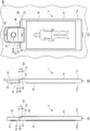
Fig. 2 is a diagram showing an external configuration of the information processing terminal of fig. 1. Fig. 2(a) is a rear view of the information processing terminal. Fig. 2(B) is a sectional view at line a-a of fig. 2 (a). Fig. 2(C) is a sectional view of fig. 2(a) from above.
The back surface 11b of the main body 11 is a surface facing the front surface 11a in fig. 1.
The coupling portion 12 is formed in a substantially rectangular planar shape and is rotatably disposed on one short side of the back surface 11b of the main body portion 11. The coupling portion 12 has a camera base 12-1 and a camera pointing portion 12-2. A circular camera 21 is disposed on the front surface (surface on the side visible in fig. 2 a) of the camera pointing part 12-2. That is, the connection portion 12 is a 2 nd housing in which the camera 21 is built. The camera 21 is an imaging unit that images an object. The image including the subject captured by the camera 21 is displayed on the display unit 13. Here, as shown in fig. 2(C), the recess width W is a width of the recess for the camera portion. The rotation radius r2 is the longest rotation radius from the rotation axis (center) of the hinge (hinge) of the 2 nd axis. Accordingly, the relationship between the recess width W and the radius of rotation r2 is expressed by the following equation (1).
w/2>r2…(1)
The camera base 12-1 is pivotally supported so that the entire coupling portion 12 is rotatable with respect to the main body portion 11 with the rotation axis Z1 as a rotation center.
More specifically, the camera base 12-1 is configured to be rotatable about a rotation axis Z1 while an end face of the columnar outer shape is in sliding contact with the main body 11.
The shaft support is preferably formed by penetrating both end surfaces from the viewpoint of strength, but may be formed by inserting rotating shafts into each other from both end surfaces to perform biaxial support, or may be formed by uniaxial support.
The camera pointing unit 12-2 on which the camera 21 is mounted can be supported on a single axis so as to be rotatable with respect to the camera base 12-1, with a rotation axis Z3 arranged in a direction substantially orthogonal to the rotation axis Z1 as a rotation center.
Here, the arrangement direction of the camera 21 is also substantially 90 degrees with respect to the rotation axis Z3.
That is, the camera 21 can move (motion) in a solid angle with respect to the main body 11 through 2 substantially orthogonal independent rotational axes of the rotational axis Z1 and the rotational axis Z3.
As described above, the portion where the camera 21 is directly or indirectly coupled to the main body portion 11 so that the camera 21 can rotate relative to the main body portion 11 by the plurality of rotation axes including the rotation axis Z1 and the rotation axis Z3 is the coupling portion 12, the rotation axis Z1 changes the angle formed by the optical axis direction of the camera 21 and the normal line direction of the display portion 13, and the rotation axis Z3 is in a direction different from the rotation axis Z1 (in this example, in a substantially orthogonal direction).
The connecting portion 12 has 1 or more movable portions having a smaller volume than the body portion 11. In this example, a camera base 12-1 and a camera pointing part 12-2 are provided as such movable parts.
The camera 21 as the imaging unit may be disposed on a predetermined surface of a predetermined 1 movable unit among the 1 or more movable units, but in this example, it is disposed on the front surface of the camera pointing unit 12-2 as described above.
An angle formed between the direction of the rotation axis Z1 and the direction of the rotation axis Z3 is substantially 90 degrees.
The information processing terminal 1 is also provided with a stand (stand)14 so that the information processing terminal 1 can be placed on a desk or the like in a standing manner.
The stand 14 is pivotally supported to be rotatable with respect to the main body 11 about a rotational axis Z2.
That is, the holder 14 is formed in a frame shape, and forms an appropriate arbitrary angle with the main body portion 11 by rotation about the rotation axis Z2, thereby stabilizing the information processing terminal 1 in a self-standing state on a horizontal plane (see fig. 5 described later).
The planar shape shown is an example of a substantially コ -shaped shape, but it is needless to say that the planar shape may be a substantially U-shaped shape or the like.
Further, the shape may be a hook (hook) shape in plan view, as long as it can be used in a vertical plane described later.
Since the holder 14 is formed in a shape surrounding the connection portion 12 in a frame shape, space efficiency can be greatly improved as compared with a case where the holder 14 and the connection portion 12 are disposed at separate positions, and unnecessary enlargement of the housing of the information processing terminal 1 can be avoided. In addition, unnecessary division of the internal substrate can be avoided.
The coupling portion 12 and the holder 14 substantially share the center line of both end surfaces with respect to the rotation axis as indicated by line a-a.
Further, the rotational axes Z1 to Z3 will be explained below.
The rotation axis Z1 is the rotation center of the connection axis between the main body 11 and the connection portion 12.
The rotation range of the rotation axis Z1 is substantially 180 degrees or more from the back surface 11b, and preferably exceeds 270 degrees.
The rotation axis Z2 is a rotation center of the connection axis between the main body 11 and the stand 14.
The rotation range of the rotation axis Z2 is preferably from the back surface 11b to 180 degrees, and particularly, an appropriate rotation resistance is given so that an arbitrary angle from the back surface 11b to 90 degrees can be maintained against the self-gravity moment of the information processing terminal 1 on the horizontal plane.
Thus, the user can stably place the information processing terminal 1 in a desired angular posture on a horizontal plane in a self-standing state.
Further, a portion offset (offset) toward the rotation axis Z2 of the stand 14 may be provided so that the rotation centers of the rotation axis Z1 and the rotation axis Z2 are shared.
The rotation axis Z3 is the rotation center of the connecting axis of the camera base 12-1 and the camera pointing part 12-2.
The rotation axis Z3 is provided substantially orthogonal to the rotation axis Z1, and rotates on a substantially orthogonal plane around the rotation axis Z1.
The rotation range of the rotation axis Z3 is preferably 180 degrees to the left and right from the substantially orthogonal plane around the rotation axis Z1 in which the rotation axis Z3 rotates.
Fig. 3 is a diagram showing a case where the coupling portion of the information processing terminal of fig. 1 is rotated.
In fig. 3 a, the coupling portion 12 (more precisely, the camera base 12-1) of the information processing terminal 1 in fig. 1 is rotated by 90 degrees about the rotation axis Z1.
In fig. 3B, the coupling portion 12 (more precisely, the camera base 12-1) is further rotated about the rotational axis Z1 from the state of fig. 3 a, and is rotated 180 degrees about the rotational axis Z1.
In fig. 3C, the coupling portion 12 (more precisely, the camera pointing portion 12-2) is rotated by 90 degrees around the rotation axis Z3 from the state of fig. 3B.
As shown in fig. 3 a to 3C, the distance h1 is the longest distance from the rotation axis (center) of the 1 st axis hinge to the upper side surface of the main body 11 of the information processing terminal 1 (smartphone), the top surface (side having the display unit 13) of the information processing terminal 1, or the bottom surface (side not having the display unit 13) of the information processing terminal 1. The distance h2 is a distance from the rotation axis (center) of the 1 st axis hinge to the rotation cross section of the 2 nd axis hinge. The relationship between the distance h1 and the distance h2 is expressed by the following expression (2).
h2>h1…(2)
Fig. 4 is a diagram showing a case where the cradle 14 of the information processing terminal 1 of fig. 1 is rotated.
Fig. 4(a) is the same state as fig. 3(B) described above, and the holder 14 is stored in the main body 11 without being rotated.
In fig. 4(B), the holder 14 is further rotated about the rotational axis Z2 from the state of fig. 4(a), and is rotated 180 degrees about the rotational axis Z2.
In addition, as in fig. 3, the relationship between the distance h1 and the distance h2 is the same as the relationship in the above equation (2).
By turning the holder 14 180 degrees around the rotation axis Z2 as shown in fig. 4(B), the user can mount the information processing terminal 1 on the wall KB by hanging the holder 14 on a Clip (Clip) CL or the like of the wall KB as shown in fig. 4 (C).
In the state of fig. 4C, the optical axis direction of the camera 21 (the imaging direction of the subject) and the normal direction of the display unit 13 (the direction in which the user views the display unit 13) are normal directions with respect to the surface of the wall KB.
Therefore, the user can easily take a picture of himself as the subject, that is, a self shot (self shot), while viewing the camera viewpoint image (image showing himself) by positioning the user in a position facing the wall KB.
As described above, the stand 14 is rotated with respect to the main body 11 by the rotation axis Z2, and the camera 21 (the connection unit 12) is rotated with respect to the display unit 13 (the main body 11) by 2 axes of the rotation axis Z1 and the rotation axis Z3.
Therefore, when a user performs self-timer shooting (self shot), the user can use the information processing terminal 1 by hanging it on the wall KB as in fig. 4, or use the information processing terminal 1 by standing it on a desk as in fig. 5.
Fig. 5 is a diagram showing a case where the information processing terminal 1 of fig. 1 is used while standing on a desk.
Fig. 5(a) is a perspective view from the viewpoint of viewing the front surface 11a side on which the display unit 13 is disposed.
Fig. 5(B) is a perspective view showing a usage form of the information processing terminal of fig. 1 on a desk, as viewed from the rear surface 11B side where the display unit 13 is disposed. The holder 14 in this embodiment is rotated within 90 degrees around the rotation axis Z2 from the state shown in fig. 4 (a).
An appropriate turning resistance is given to the turning shaft Z2 so that an arbitrary angle from the back surface 11b to 90 degrees can be maintained against the self-gravity moment of the information processing terminal 1 on the horizontal plane.
Thus, the user can stably place the information processing terminal 1 in a desired angular posture on a horizontal plane in a self-standing state.
When the user of the information processing terminal 1 shown in fig. 1 photographs himself or herself, the information processing terminal 1 in a state in which the main body 11 and the stand 14 are deformed so as to be spread at a predetermined angle is set upright on a desk or the like as shown in fig. 5.
Even in this state, the information processing terminal 1 can direct the camera 21 toward the subject by rotating the rotation axis Z1 and the rotation axis Z3.
Further, the information processing terminal 1 can perform shooting without holding the main body 11 by using the shutter remote control function and the self-timer (self timer) function in combination, and thus various problems described later can be solved.
By using the information processing terminal 1 to which the present invention is applied as described above, various effects can be obtained as follows.
In other words, a self shot (self shot) using a front camera in a conventional smartphone is widely popular around the world, particularly in asian circles.
However, conventional smartphones have various problems as follows.
By adopting the information processing terminal 1 to which the present invention is applied, an effect that these various problems can be solved can be obtained.
For example, since a user using a conventional smartphone presses a shutter with his hand, the user cannot take his picture from a distance greater than or equal to the length of his hand. That is, due to the limitation of a wide angle, there is a possibility that all persons (family, lover, friend, etc.) who want to take pictures together do not enter the scene, or cannot take a full-body picture of themselves.
As a conventional solution to this problem, there is a method using a selfie stick (selfie stick). In this method, although a picture can be taken from a distance exceeding the length of the hand of the user, the picture cannot be taken from a distance exceeding the length of the self-timer stick. Further, since the selfie stick is required to be carried, places where the use of the selfie stick is prohibited from the viewpoint of safety (theme parks, sports facilities, concert halls, station platforms, etc.) also appear in succession, which is not a universal solution.
That is, there is a problem that it is intended to perform photographing without using a selfie stick. The solution to this problem is to use the information processing terminal 1 to which the present invention is applied. That is, the information processing terminal 1 to which the present invention is applied can be fixed to a wall or a desk as shown in fig. 4 and 5 because it has the stand 14, and does not need a selfie stick.
Further, since the user's hand is extended, the user can only take a photograph with the shutter hand extended, and the posture of the user is unnatural.
In this regard, although a self-timer stick may be used to alleviate a small degree of unnaturalness, the unnaturalness may remain and a posture (for example, a posture using both hands or the like) in which the user wants to photograph the image may not be made.
That is, there is a problem that it is intended to perform photographing without using a selfie stick. The solution to this problem is to employ the information processing terminal 1 to which the present invention is applied. That is, the information processing terminal 1 to which the present invention is applied can be fixed to a wall or a desk as shown in fig. 4 and 5 because it has the cradle 14 and the self-timer and shutter remote control functions, and does not need a self-timer stick.
Further, when a larger number of self-timer shots are taken, it is sometimes impossible to take all people into the camera with either the hands or the self-timer stick, rather than a self-timer shot.
In this case, one of the friends is sacrificed to become the photographer, but the photographer cannot enter the group photo.
When a shop is opened, a store clerk is often held to help shoot a group photo, but the need to call the store clerk is troublesome.
That is, there is a problem that all the subjects are put in the photograph without bothering the hands of the persons other than the subjects. The solution to this problem is to use the information processing terminal 1 to which the present invention is applied. That is, the information processing terminal 1 to which the present invention is applied can be fixed to a wall or a table as shown in fig. 4 and 5 because it has a 2-axis rotation mechanism including the cradle 14 and the camera, and does not require the hands of people other than the subject to be photographed.
Further, for example, when the user confirms the posture of the exercise himself/herself, the user wants to perform imaging using a camera of a smartphone, but if the smartphone is not fixed to an object such as a floor or a desk, the user often fails to perform imaging and abandons imaging using the smartphone.
Similarly, a self-timer shooting may be performed by placing the smartphone on a desk or the like, but when the smartphone is placed with the front camera facing the subject, the smartphone cannot be placed stably or the placement takes time.
That is, there is a problem in that photographing is desired without using a tripod. The solution to this problem is to use the information processing terminal 1 to which the present invention is applied. That is, the information processing terminal 1 to which the present invention is applied can be fixed to a wall or a table as shown in fig. 4 and 5 because it has a 2-axis rotation mechanism including the stand 14 and the camera, and does not need a tripod.
In addition, when photographing is desired in a vertical screen, photographing can be performed in a state of being fixed to a table by raising the stand 14 and rotating the coupling portion 12 by 180 degrees or more as shown in fig. 9, and therefore, a tripod is not required. In this case, the stand 14 does not necessarily need to be erected.
In addition, when using a smartphone for video chat, many people need to hold the smartphone all the time during the chat in order to show their face to the front camera of the smartphone.
According to the survey, 80% of people answer to chat for a handheld smartphone, and the hands become fatigued, although depending on the time of the chat.
That is, there is a problem in that a video chat is desired without holding a smartphone. The solution to this problem is to use the information processing terminal 1 to which the present invention is applied. That is, the information processing terminal 1 to which the present invention is applied can be fixed to a wall or a desk as shown in fig. 4 and 5 because it has the stand 14 and the rotation mechanism of the camera, and does not need to hold a smartphone.
In addition, when a user wants to take a picture of his or her face on a vertical screen and perform a video chat, the user can take a picture while the user is fixed to a desk by raising the stand 14 and rotating the connection portion 12 by 180 degrees or more as shown in fig. 9, so that the user does not need to hold a smartphone by hand. In this case, the stand 14 does not necessarily need to be erected.
As a solution to these problems, there is a method of mounting a stand on a smartphone for placing the smartphone on a desk or the like, but since the angle between the display screen and the front camera is fixed by the stand, the camera does not necessarily face the subject, and these are not a versatile solution for the purpose of taking a picture or image.
That is, there is a problem in that it is desired to perform imaging without using a front camera whose angle is fixed. The solution to this problem is to use the information processing terminal 1 to which the present invention is applied. That is, since the information processing terminal 1 to which the present invention is applied has the 2-axis rotation mechanism of the stand 14 and the camera, the rear camera can be rotated to a front side by 2-axis rotation and directed to an arbitrary angle as shown in fig. 4 and 5, and a front camera having a fixed angle is not required.
In addition, when photographing is desired in a vertical screen, photographing can be performed in a state of being fixed to a table by raising the stand 14 and rotating the coupling portion 12 by 180 degrees or more as shown in fig. 9, and therefore, a front camera with a fixed angle is not necessary. In this case, the stand 14 does not necessarily need to be erected.
Furthermore, even if it is assumed that the smartphone has a stand, the smartphone cannot be placed if there is no place to place, only a wall.
As a solution to this problem, there is also a method of fixing the information processing terminal by hanging it on a wall, but a hook for the information processing terminal needs to be prepared in the smartphone, which also requires a space for the smartphone main body.
That is, there is a problem in that it is not desirable to additionally prepare the hook. The solution to this problem is to employ the information processing terminal 1 to which the present invention is applied. That is, the information processing terminal 1 to which the present invention is applied can be suspended and supported on a flat surface by the projection or the pin-like member by the gap provided between the holder 14 and the connecting portion 12 by rotating the connecting portion 12 and the holder 14 by 180 degrees, and therefore, is suitable for wall hanging and does not require a separate hook.
Furthermore, front cameras generally have the following disadvantages in performance compared to rear cameras:
(A) low resolution
(B) Low sensitivity (shooting in dark scene without flash)
(C) Fixed focus, not automatic focusing
(D) Although there are cameras with auto-focusing, the speed of auto-focusing is slow
(E) Low zoom factor
(F) Without flash lamp
It is impossible to perform imaging with good image quality.
Also, in the case where the rear camera and the front camera have different performances, it is necessary to develop 2 cameras for 1 model.
As a solution to this problem, there is an application of taking a self-timer image with a rear camera, but since the display portion cannot be seen, usability is very poor with a voice manipulation (navigator) or the like.
That is, there is a problem that it is not desirable to use an application program for taking a self-timer photograph without looking at the display section. The solution to this problem is to use the information processing terminal 1 to which the present invention is applied. That is, the information processing terminal 1 to which the present invention is applied can direct the camera 21, which is a high-performance camera, in an arbitrary direction with respect to the terminal body, and can photograph in an arbitrary posture while viewing the camera viewpoint image, and therefore, application software for photographing a self-portrait without looking at the display unit 13 is not necessary.
Further, the stand and the swivel type camera as the above-described solutions require respective shafts for swiveling to the main body side, and a space for these 2 shafts needs to be secured, resulting in a larger housing of the main body. Further, although the camera is rotated, the camera is not always directed to the subject even if the camera of the smartphone, which is erected using the stand, is rotated, and thus the solution is not always possible. Although the rotation axis can be further increased so that the camera faces the subject, there are many cases where it is troublesome to take a picture after the camera is always directed to the subject when taking a picture.
That is, there is a problem that it is desired to always direct the camera toward the subject with a small number of rotational axes. The solution to this problem is to use the information processing terminal 1 to which the present invention is applied. That is, since the information processing terminal 1 to which the present invention is applied can use the rotation axes of the stand 14 and the camera 21 in common, the camera 21 can be always directed to the subject by rotating only 2 axes as shown in fig. 4 and 5, and there is no need to increase the rotation axis.
In addition, in the information processing terminal in which both the rear camera and the front display unit are fixed to the main body in the related art, a high angle shot (high angle shot) for taking an image from a position higher than the eyes and a low angle shot (low angle shot) for taking an image from a position lower than the waist are opposed to each other in the direction of the camera and the direction of the display unit, and therefore, it is difficult to take an image while looking at the display unit.
For example, in taking a photograph, when the subject is gathered in a crowd, for example, when the subject is taken from above the crowd, it is necessary to take a picture in a downward direction.
Similarly, when the camera is directed from a position lower than the waist toward the subject located higher than the camera, the display unit is directed downward, and the camera cannot capture the image while viewing the camera viewpoint image.
As a solution to this problem, since the orientation of the camera and the orientation of the display unit can be set separately when the camera is rotated, shooting can be performed while viewing the camera viewpoint image.
In this case, when the camera starts to rotate, the vertical direction of the screen may be changed, but if this is not described, the vertical direction may be reversed.
In such a forward-looking or backward-looking shooting, if the direction of rotation of the camera is fixed (such as clockwise rotation from the normal position), it is difficult to perform shooting, and therefore it is preferable to be able to rotate in both directions.
That is, there is a problem in that it is desired to perform imaging without using a rear camera whose angle is fixed. The solution to this problem is to use the information processing terminal 1 to which the present invention is applied. That is, since the information processing terminal 1 to which the present invention is applied has the 2-axis rotation mechanism of the cradle 14 and the camera 21, the rear camera 21 can be directed to an arbitrary angle in the vertical direction by 2-axis rotation as shown in fig. 4 and 5, and a rear camera having a fixed angle is not necessary.
When the camera 21 is rotated, it is preferable to automatically switch an angle of view (wide angle, normal angle, narrow angle, etc.) that can be photographed at a certain timing. In general, on the optical axis direction side of the front camera, the distance to the subject is often short, and therefore, it is desirable to perform imaging with a wide angle, while on the optical axis direction side of the rear camera, imaging with a normal angle of view or a narrow angle is desirable. Therefore, it is preferable that the angle of view is automatically changed according to the orientation of the camera.
In addition, when a self-timer is taken, the shutter button or the touch panel needs to be pressed to drop the shutter, so that the smartphone cannot be firmly held, and an unstable smartphone may be dropped.
As a solution to this problem, there is a shutter press using timer setting, gesture recognition, or voice recognition, but the time when the shutter falls is not easily known, or the response is not good, and it is difficult to use the shutter when shooting the moment when 5 people jump up, for example.
That is, there is a problem in that the user wants to release his hand from the smartphone and press the shutter button to perform shooting. The solution to this problem is to use the information processing terminal 1 to which the present invention is applied. That is, since the information processing terminal 1 to which the present invention is applied has a shutter remote control supporting function, it is possible to drop the shutter without pressing the shutter button or the touch panel at the time of self-timer shooting as shown in fig. 4 and 5, and it is not necessary to hold the smartphone firmly.
Here, even if the shutter remote control supporting function is provided, for example, when a group shot (group shot) of 10 persons is photographed, the information processing terminal 1 is set on a desk or the like and the camera 21 is rotated toward the 10 persons, the display section 13 is small and invisible when the information processing terminal 1 is far away, and it may be difficult to press the shutter for the reason that it is unknown whether all the persons are contained in the frame (frame) of the camera viewpoint image or the expression of each person is unknown.
That is, there is a problem that it is desired to capture an image while checking a camera viewpoint image by some method.
The following method is adopted as a solution to this problem. That is, the information processing terminal 1 to which the present invention is applied may be equipped with a screen sharing function that can be operated by transmitting a camera viewpoint image to another information processing terminal such as a smartphone or a personal computer by wire or wirelessly.
This allows the camera viewpoint image of the information processing terminal 1 to be shared with another information processing terminal, and still images and moving images to be captured from a remote position. If there is a case where information processing terminals are directly connected to each other, it is also possible to share a camera viewpoint image of the information processing terminal 1 placed at one's home with a personal computer in an office using a network connection and to photograph a pet left at one's home while viewing the screen of the personal computer.
In addition, even in a conventional digital camera or smartphone, a synthesized panorama (Panoramic shot) can be photographed by moving the camera laterally.
However, it is often necessary to perform imaging while moving the smartphone and camera in the lateral direction, and the imaging cannot be combined well.
That is, there is a problem that the periphery is photographed by the camera without moving the main body in the lateral direction. The solution to this problem is to use the information processing terminal 1 to which the present invention is applied. That is, in the information processing terminal 1 to which the present invention is applied, since the rotation of the rotation axes Z1 and Z3 of the camera 21 may be electric, the camera 21 can be translated (pan) in a state where the main body is stopped as shown in fig. 3, and it is not necessary to move the camera 21 laterally.
Further, conventionally, it has been attempted to utilize human gestures for operations of devices and games, but since a camera for recognizing gestures needs to be directed to a subject at all times, it is necessary to prepare a camera terminal and a game terminal separately, and it is impossible to handle them with 1 smartphone.
Also, cameras used for gesture recognition are very expensive, creating additional costs.
That is, there is a problem that gesture recognition is desired to be performed without using a camera dedicated to gesture recognition. The solution to this problem is to employ the information processing terminal 1 to which the present invention is applied. That is, the information processing terminal 1 to which the present invention is applied only needs to have a high function (for example, gesture recognition by abstraction) in the camera 21 directed to the person, and does not need a camera dedicated to gesture recognition.
In addition, although navigation software for pedestrians is conventionally available in smartphones, it is not easy to know the direction in which the smartphone is facing, and the direction in which the smartphone is going to travel is unknown, and it takes time to clarify the direction, particularly outdoors.
As a solution to this problem, there is navigation based on AR using a camera.
This navigation system can be used as it is without taking time to recognize the orientation through a user interface in which an arrow is superimposed on the image actually captured by the camera.
However, in order to perform imaging using a camera having a fixed angle perpendicular to the back surface of the main body, the smartphone main body needs to be held perpendicular to the floor surface, and the display unit becomes an angle that is extremely difficult to view, and the smartphone is always held and fatigued.
The act of using a smartphone during outdoor walking, i.e. "go while playing a mobile phone", also becomes a social phenomenon, and is not as noticeable to hit because of being focused on the picture.
These 2 problems can be solved by using a rotary camera.
In the case of "playing the mobile phone while walking", the image of the camera 21 can be displayed on the display unit 13 as one of the windows, or the presence of an obstacle can be transmitted by sound, a screen, or vibration, so that danger can be avoided.
In this embodiment, since the camera is rotated in the longitudinal direction with respect to the display surface, the above 2 problems can be solved, but there are also the following problems: in the case where the orientation of the camera is smoothly rotated, the camera moves and is unstable.
That is, there is a problem that the camera moves and becomes unstable even if the main body is gripped and stabilized. The solution to this problem is to use the information processing terminal 1 to which the present invention is applied. That is, the information processing terminal 1 to which the present invention is applied may lock the rotation of the camera 21 at a specific angle, and the camera 21 may be stabilized by holding the main body 11.
In recent years, there has been a rapid development of a drive recorder (drive recorder) mounted on an automobile or a bicycle, which is intended to contribute to objective verification of an accident by recording video data, data obtained from a GPS (global positioning system), and the like at the time of the accident.
Although it is also possible to replace the tachograph by installing application software on a smartphone, it is less common.
As a reason for the case of an automobile, when a holder for fixing a smartphone or the like to an automobile dashboard with a suction cup, a double-sided tape, or the like is used to fix the smartphone so that a driver can easily view a display unit, the optical axis direction of a camera of the smartphone does not face the front or rear of the vehicle to be photographed, and the dashboard is photographed.
That is, when the smartphone is placed at a position where the driver can easily view the smartphone and the smartphone does not interfere with driving, the smartphone cannot function as a drive recorder. On the other hand, when the image as the driving record is prioritized, the smartphone must be set in a position where the driver cannot easily view it. This makes it impossible to satisfy the dual use of a smartphone as a car recorder/navigation system or the like. The same is true in the case of a bicycle. Therefore, it can be considered that the case of using a smartphone as a drive recorder is less common.
That is, there is a problem that the smartphone is used as a drive recorder and is also used for other purposes.
The solution to this problem is to use the information processing terminal 1 to which the present invention is applied. That is, the information processing terminal 1 to which the present invention is applied can direct the camera 21 in an arbitrary direction with respect to the terminal body, and can display a camera viewpoint image in the form of Picture-in-Picture (Picture) on a part of the screen while displaying a navigation map, and therefore can be used for other purposes as well while using a smartphone as a drive recorder. Thus, a dedicated drive recorder is not required.
Further, the camera 21 can be rotated about 2 axes, for example, when the car is installed so as to form a landscape screen, and the bicycle is installed so as to form a portrait screen, and thus the present invention can be applied to a wide range of installation methods.
In the smart phone industry, in the future, there are an increasing number of examples in which a plurality of sensors are mounted on a rear camera, and not only a photograph but also a distance measurement or effective use for zooming is seen. However, when the front camera also performs the same correspondence, the cost is doubled, and therefore, there is a high possibility that the consideration is suspended, and the functions of the camera differ between the front and rear positions.
That is, there is a problem that only the rear camera can be made highly functional. The solution to this problem is to use the information processing terminal 1 to which the present invention is applied. That is, the information processing terminal 1 to which the present invention is applied can solve the problem if there is a rotating camera 21, assuming that it is applied to a stereo camera, and does not need to deal with the addition of a function to a front camera.
The present invention is not limited to the above-described embodiments, and modifications, improvements, and the like are included in the present invention within a range in which the object of the present invention can be achieved.
For example, although the connection portion 12 is configured by 2 movable portions, i.e., the camera base portion 12-1 and the camera pointing portion 12-2, in the above embodiment, the present invention is not particularly limited to the above embodiment, and it is sufficient that the connection portion 12 has 1 or more movable portions having a smaller volume than the main body portion 11.
In this case, the camera 21 as the imaging unit may be disposed on a predetermined surface of a predetermined 1 movable unit among the 1 or more movable units.
Further, any device having any function can be mounted on any number of any kinds of movable portions (including the movable portion on which the imaging portion is disposed) among the 1 or more movable portions.
For example, as shown in fig. 6, a projector 22 may be mounted on the camera pointing unit 12-2 on which the camera 21 as an imaging unit is mounted.
Fig. 6 is a diagram showing a case where the coupling portion of the information processing terminal according to the embodiment of the present invention, that is, the embodiment different from fig. 1, is rotated.
In fig. 6 a, the coupling portion 12 (more precisely, the camera base portion 12-1) of the information processing terminal 1 of fig. 1 is rotated 180 degrees around the rotation axis Z1.
In fig. 6B, the coupling portion 12 (more precisely, the camera pointing portion 12-2) is further rotated 90 degrees to the right (as viewed from the front 11a side of the main body portion 11) about the rotation axis Z3 from the state of fig. 6 a. As shown in fig. 6B, a circular camera 21 is disposed at the approximate center of the front surface (surface on the side visible in fig. 6B) of the camera pointing part 12-2.
In fig. 6C, the coupling portion 12 (more precisely, the camera pointing portion 12-2) is further rotated 90 degrees to the left (as viewed from the front 11a side of the main body portion 11) about the rotation axis Z3 from the state of fig. 6 a. As shown in fig. 6C, a circular projector 22 is disposed at the approximate center of the rear surface (the surface facing the front surface and visible in fig. 6C) of the camera pointing portion 12-2.
In addition, as in fig. 3, the relationship between the distance h1 and the distance h2 is the same as the relationship in the above equation (2).
In the information processing terminal 1 according to the embodiment of fig. 6, the cradle 14 is rotated with respect to the main body portion 11 by the rotation axis Z2, and the camera 21 (the coupling portion 12) is rotated with respect to the display portion 13 (the main body portion 11) by 2 axes of the rotation axis Z1 and the rotation axis Z3.
Therefore, when the user performs self-shot (self shot), the information processing terminal 1 can be used while standing on a table as shown in fig. 7.
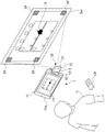
Fig. 7 is a diagram showing a case where the information processing terminal 1 of fig. 6 is used while standing on a desk.
The camera 21 photographs the user U. The display unit 13 displays a camera viewpoint image including an image Ug1 of the user U, which is a captured image of the camera 21.
Further, as shown in fig. 7, in the camera pointing part 12-2, a projector 22 is disposed on the rear surface facing the front surface on which the camera 21 is disposed. Thereby, the projector 22 can also project the camera viewpoint image including the image Ug2 of the user U, which is the image captured by the camera 21, onto the screen Scr.
As a result, the camera viewpoint image can be viewed by the user U through the display unit 13, and can also be viewed by other people not shown through the screen Scr.
The image displayed on the display unit 13 and the image projected on the screen Scr by the projector 22 do not particularly have to be identical to each other as in the example of fig. 7, and may be different images.
For example, if the information processing terminal 1 is used as a videophone, one of the display unit 13 and the screen Scr may display an image of the user U (a camera viewpoint image of the camera 21), and the other may display an image of the opposite party.
For example, the camera 21 and the projector 22 may be disposed on the same surface or different surfaces, even if they are not disposed at positions facing each other in the coupling section 12 as described above.
In fig. 6 and 7, since the camera 21 and the projector 22 are mounted on the same movable portion (the camera pointing portion 12-2), one of the imaging direction of the camera 21 and the projection direction of the projector 22 is limited. Therefore, although not shown, a movable portion different from the camera pointing portion 12-2 may be provided, and the projector 22 may be mounted on the movable portion. This allows the imaging direction of the camera 21 and the projection direction of the projector 22 to be directed in any direction independently of each other.
For example, in the above-described embodiment, the holder 14 is configured to be rotated about the rotation axis Z2 that is located at a position perpendicular to the longitudinal direction of the main body 11, but is not particularly limited.
Fig. 8 is a diagram showing a case where the information processing terminal according to the embodiment of the present invention is used on a desk, which is different from the embodiments of fig. 1 and 6.
In the information processing terminal 1 according to the embodiment of fig. 8, the cradle 23 is in the following state: the camera 21 is set to a self-portrait (self shot) orientation by being rotated about 50 degrees toward the back surface 11b around the rotation axis Z4 to be set upright on the desk, and further, the rotation axis Z1 and the rotation axis Z3 are also rotated.
The holder 23 has substantially the same outer dimensions as the short side of the main body 11, and is configured to be physically integrated with the main body 11 by setting the opening degree with respect to the main body 11 to zero, thereby constituting the lower end portion of the entire information processing terminal 1.
The rotation axis Z4 couples the main body 11 and the bracket 23 to be rotatable at one corner of the main body 11.
The axis of the rotation axis Z4 is substantially parallel to the long side of the main body 11. Appropriate rotational resistance is given so as to be stable in a self-standing state against the self-gravity moment of the information processing terminal 1. Further, a place where the rotation can be stopped in the middle may be provided at a plurality of places within 90 degrees of the opening.
The pivot axis Z4 allows the holder 23 to pivot at least within 90 degrees of the rear surface 11b side, and allows the opening between the main body 11 and the holder 23 to be zero as described above.
As described above, since the axial direction of the rotational shaft Z4 is substantially parallel to the long side of the main body 11, the rotational angle of the rotational shaft Z4 when the user stands the information processing terminal 1 on a table and uses it in landscape (landscape) as shown in fig. 8 for self-shooting (self shot) or the like is matched with the standing angle of the main body 11, and this angle is easily adjusted.
In other words, the cradle 23 can be set to the usage state of fig. 8 by pulling up the main body 11 side from the state where the information processing terminal 1 is horizontally placed on a desk to the state where it is placed on the desk. Further, by smoothly pressing the main body 11 side against the desk from this state, the information processing terminal 1 can be shifted to a horizontally placed state with higher stability without being lifted up.
In the case of the stand 23, since the angle can be finely adjusted, the camera can be perfectly directed to the subject even if it is not a 2-axis camera as long as the subject is positioned above the front camera or the 1-axis rotary camera.
Fig. 9 is a diagram showing a case where the information processing terminal of fig. 1 is used while standing on a desk.
Fig. 9 a is a perspective view showing a case where the table is used while standing in portrait (portrait) on the table.
Fig. 9B is a side view showing a case where the chair is used while standing on a table in a portrait position.
In the information processing terminal 1 according to the embodiment of fig. 9, the cradle 14 is in the following state: the camera 21 is set in an orientation in which the self-portrait (self shot) can be taken in a portrait (portrait) by rotating the back surface 11b side by less than 90 degrees around the rotation axis Z2 so as to be set upright on the table and further rotating the rotation axis Z1.
For example, in order to use the information processing terminal 1 comfortably in a video chat, the receiving side can be switched to vertical holding or horizontal holding according to whether the communication partner photographs in vertical holding or horizontal holding.
If the user of the communication partner takes a picture while holding it in the portrait orientation but cannot take a self picture while setting the information processing terminal 1 upright in the portrait orientation, the user of the communication partner continues to hold the information processing terminal 1 in his or her hand, or stops holding the partner in the portrait orientation and forcibly takes a picture while holding it in the landscape orientation, or both of them must endure that the images of each other are displayed on the display portion very little or not completely.
However, since the information processing terminal 1 of fig. 1 includes the holder 14 and the rotation mechanism of the imaging section, even when there is no suitable wall surface around the information processing terminal, and there is no fixed object such as a projection or a pin that can be supported in a suspended manner, it is possible to perform self-portrait on a desk in portrait (portrait), and as a result, various problems such as a burden of holding the information processing terminal 1 in portrait (portrait) continuously and hand shake during hand-held imaging are eliminated.
The application program of the camera 21 may be automatically started when the coupling section 12 is raised by rotating the rotation shaft Z1.
By doing so, the application of the camera 21 does not need to be constantly started to prepare for a sudden photo opportunity, and limited and precious battery power is not wasted.
Further, the following mechanism may be adopted: an "open button" for automatically rotating the rotation shaft Z1 is provided at a position such as a side surface of the main body 11 where a pressing operation is easy, and the connection portion 12 is easily raised by the pressing operation.
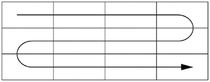
In general, when taking a picture or a video with a delay, a method of fixing a camera with a tripod and taking pictures at regular intervals is adopted, but there is a problem that many equipment such as a tripod is required. Further, there is a demand for performing shooting by moving the orientation of the camera in accordance with, for example, the movement of the sun without completely fixing the camera in shooting time lag shooting, and in this case, it is necessary to add a device such as a slide stand (dolly) for moving the camera, and the setting thereof needs to be performed separately from the camera.
However, according to one embodiment of the information processing terminal of the present invention, as shown in fig. 10, the information processing terminal 1 has a 2-axis rotation mechanism as shown in fig. 4 and 5, and is provided with the stand 14, the camera 21, and the like, so that the camera 21 can be fixed and a photograph or a moving image of the Sun seen from the window MD taken with a delay can be taken without using a fixing device such as a tripod.
Further, since the information processing terminal 1 shown in fig. 10 has a plurality of turning axes such as the turning axes Z1 to Z4 described above, it is possible to take a picture or video taken with a delay by setting the orientation of the camera to move in accordance with the motion of an object moving at a low speed such as the Sun in advance without additionally using a device such as a slide stand.
The information processing terminal 1 can rotate the camera in the horizontal direction at an angle shown in fig. 11(a), and can rotate the camera in the vertical direction at an angle shown in fig. 11(B), for example.
When taking a picture of a target object, it is sometimes desired to hide a background located further behind the target object for reasons such as not to expose a messy room, or to set a white background in order to attract attention to people and commodities. Conventionally, vignetting is created using a lens of a camera, or depth is calculated using 2 or more cameras, but in the case of 1 camera of a general smartphone or a lens of a smartphone, it is difficult to vignetting or eliminate the background with high accuracy and perfectly.
However, according to an embodiment of the information processing terminal of the present invention, as shown in fig. 12 and 13, the information processing terminal 1 can eliminate or vignette only the background of the photographed image.
First, an image showing the object Obj is captured as in fig. 12(a), and an image showing only the background and not showing the object Obj is captured before and after the image as in fig. 12 (B). Further, by leaving only the difference between the image of fig. 12(a) and the image of fig. 12(B), an image in which only the object Obj such as a product or a person is left can be created as shown in fig. 12 (C). Further, if an image in which only the object Obj is left can be created as shown in fig. 12(C), an image in which only the background image is blurred can be created as shown in fig. 13(F) by combining the image with an image in which only the background image is blurred as shown in fig. 13 (D). In addition, in a moving image, only a moving object can be displayed by performing the same processing as in the image, and the moving image can be used for video analysis by a monitoring camera or the like.
For example, there are cases where it is desired to take a comparison image or a comparison video with a past photograph, for example, it is desired to compare a photograph of a house before finishing (renovation) with a photograph after finishing, and to compare the photographs in order to confirm the effect of a detergent. On the other hand, there is basically no application to cameras and smartphones that can take pictures with the same composition while viewing past pictures.
However, according to an embodiment of the information processing terminal of the present invention, a comparison image or video with a past photograph can be easily taken. As shown in fig. 14(a) and (B), the information processing terminal 1 can display past photo data semi-transparently or can display a photo to be compared with a live view screen of a camera to be photographed by 1 button, and can automatically return to the live view screen of the camera or return to the live view screen of the camera by 1 operation (pressing a button, pressing a button of a remote controller, operating with voice, etc.), and thus can easily photograph the compared photo.
For a person who is used to operate a smartphone or a tablet computer, it may be difficult to understand a UI (user interface) that cannot be directly operated on a viewed icon. Therefore, although there is a device that can be projected as a large screen by a projector and operated by touching the projected screen, such as Xperia touch, on the market, there are many restrictions such as high cost and inability to touch if the projection distance exceeds a certain distance. Further, the larger the screen is, the more the user needs to move the hand greatly before the screen for touching, and the user is difficult to say that the use is easy. That is, it is difficult to make the close-distance operation performed with the hand held for each screen and the remote-distance operation performed with the screen away the same.
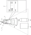
However, according to an embodiment of the information processing terminal of the present invention, as shown in fig. 15, the video displayed on the display unit 13 of the information processing terminal 1 can be outputted wirelessly or by wire to a large-screen through a TV, a projector, or the like, and the operation can be performed by a device that can be displayed superimposed on the screen by a laser pointer LP, or the like. At this time, for example, 3 or more marks 24 can be displayed on the screen Scr as a part of the video. Further, by capturing the cursor (cursor) P of the laser pointer LP and 3 or more markers 24 with the camera 21 of the information processing terminal 1, the relative positional relationship between the image on the screen Scr and the cursor P is known. The laser pointer LP may be provided with a button for enlargement or reduction of the cursor P in addition to the on/off button of the cursor P, and the button for enlargement or reduction may be integrated with the on/off button of the cursor P. Changes such as changes in the color and shape of the cursor may be added during enlargement or reduction of the screen. The number of the cursors P is not limited to 1, and a plurality of cursors can be simultaneously recognized. When the enlargement and reduction operations are performed, it is also possible to perform a determination that the image is enlarged when the 2 points are gradually separated and the image is reduced when the 2 points are gradually approached. In order to clearly recognize the cursor P with the information processing terminal 1, the trajectory of the cursor P can be recognized more clearly by capturing in real time the video output to the display unit 13 of the TV, the projector, or the like, and the video displayed on the TV, the projector, or the like, and the video on the screen on which the cursor P is also displayed, and leaving only the difference.
The screen output to the display unit 13 of the information processing terminal 1, the television receiver, and the projector need not necessarily match. For example, the image being captured by the camera 21 may be displayed on the display unit 13 of the information processing terminal 1, or may be displayed without necessity for the purpose of reducing the processing or the like.
With a notebook computer and the like, there are increasing nomadic office workers (nomad workers) who do not have fixed offices and seats even at the destination offices. However, if a notebook personal computer or the like carries a large amount of luggage, the luggage is heavy or too large when carried, and it is troublesome to carry the luggage. On the other hand, when a personal computer is not carried but a smartphone is used, since there is no physical keyboard, it takes time to input characters. Although voice input is also possible, it cannot be used in a quiet office. Although dedicated thin keyboards and the like are sold, it is costly to purchase them one by one. There is also a problem that it is not practical for a manufacturer who manufactures a keyboard to manufacture or specially customize a keyboard for a particular language that is not sold well.
On the other hand, according to one embodiment of the information processing terminal of the present invention, as shown in fig. 16, since a keyboard printed on an extremely thin material such as paper can be used, it is excellent in portability and manufacturing cost. In the information processing terminal 1 of fig. 16, the camera 21 is fixed by using the stand 14 to stand the information processing terminal 1 and the 2-axis camera rotation mechanism is used, whereby the printed keyboard K is photographed, the fingers placed on the keyboard K are photographed by the camera, and the positions of the pressed fingers can be detected. For example, by capturing an image of a QR code (registered trademark) QR printed next to the keyboard K with the camera 21, it is possible to specify a layout of buttons of the printed keyboard K as one type. For example, by printing 3 or more marks 24 on the side of the keyboard K, the button area of the keyboard K can be specified, and the relative position of the button pressed by the key can be known, and character input can be performed by pressing the printed keyboard K with the finger. A keyboard of a usual configuration like that shown in fig. 17 can be used as a matter of course, but since the keyboard K can be manufactured by printing, it can be customized as needed regardless of the sales volume. For example, by making "good morning". "I am suzuki-jieer. "" is. "" is started. The buttons such as "may be input not in a word-by-word manner but in a unit of a generalized sentence. With this application, a game pad, a musical instrument, a mixer for video editing, a DJ mixer, and a musical instrument can also be manufactured by printing. Handwritten characters and illustrations (handwriting) can also be input by handwriting by shooting with a camera.
When the smartphone is placed on a desk and is erected by a stand or the like, the smartphone main body may move backward, the smartphone may fall down, or the stand of the erected smartphone may fall down due to touching the display of the main body when the smartphone is touched.
On the other hand, according to one embodiment of the information processing terminal of the present invention, as shown in fig. 18, the movement of the finger Fn and the touch operation on the desk are captured by the camera 21 without directly operating the information processing terminal 1, and the operation of the finger Fn and the operation of the cursor P can be operated in the same manner as when the touch panel of the personal computer is operated in conjunction with each other. Similarly, if the index finger is moved up and down with the thumb fixed, the operation can be performed as when the jog wheel (jog dial) of the mouse is moved. Handwritten characters can be input by the same key.
As a car navigation system, many people use a navigation application of a smartphone without using a dedicated device. However, the road may be misrouted for reasons such as the actual landscape and the impression obtained on the map being different. In order to prevent such a wrong way, there is AR navigation, but when used as AR navigation, the smartphone must be set at an angle that is not easily visible to the driver. Or, it must be installed at a position having an influence on driving. The use of the vehicle drive recorder also causes the same problem.
On the other hand, according to an embodiment of the information processing terminal of the present invention, as shown in fig. 19(a) and (B), the information processing terminal 1 has a camera 21 that can rotate with a plurality of rotation axes. Therefore, the information processing terminal 1 can be fixed to the navigation holder 25, and the display unit 13 of the information processing terminal 1 can be oriented at an angle that is easy for the driver to see while capturing an image in the traveling direction using the camera 21 as an AR navigation device or a drive recorder.
In driving a car or the like, a drive recorder and a car navigation system are generally used. In these devices, it is sometimes possible to predict that the driver has some problems, such as possible fatigue driving, possible drunk driving, etc., from the behavior of the vehicle. However, this is also only presumed from the movement of the vehicle, and the driver's state cannot be directly investigated.
On the other hand, according to one embodiment of the information processing terminal of the present invention, the camera 21 of the information processing terminal 1 normally captures the traveling direction as shown in fig. 20(a), but when a danger or the like is detected, the camera 21 rotates to capture the face or the like of the driver as shown in fig. 20(B), and the health state of the driver can be checked.
There are fixed cameras such as Amazon Echo look that can photograph a suit worn every day, but if the position of each shot is not calibrated, the size of a person that can be photographed varies, or the posture is messy and cannot be compared favorably.
On the other hand, according to one embodiment of the information processing terminal of the present invention, the current captured image shown in fig. 21(a) and the previous photograph shown in fig. 21(B) for example can be compared, the camera 21 and the swivel-type mount 26 can be electrically swiveled and adjusted so that the object Obj comes to an appropriate position, and guidance for determining the posture can be shown on the display unit 13 so that the posture becomes the same. As a guide, for example, contents handwritten by the user can be displayed. Further, the health state can be checked at the same time as shooting, and the shutter can be pressed by voice or gesture.
In the case where the AR walker navigates using a rotating camera, there is a problem that when the orientation of the smartphone is changed, the orientation of the camera also changes, and the person looking at the display gets dizzy.
On the other hand, according to one embodiment of the information processing terminal of the present invention, as shown in fig. 22(a) to (C), the image displayed on the display unit 13 of the information processing terminal 1 can be kept constant by electrically controlling the camera 21 using the data of the G sensor and the like so that the rotation axis Z1 always faces a certain direction (for example, the horizontal direction).
In order to read a book written in a language which cannot be understood by the user, the user needs to understand the meaning of the book by grasping the language or wait until the book is translated into the user's language, which makes it difficult for the user to immediately read the book.
On the other hand, according to an embodiment of the information processing terminal of the present invention, as shown in fig. 23, by photographing a book B with a camera 21, applying OCR, text data can be recognized, and a translation can be displayed on the display unit 13 of the information processing terminal 1. The pages of book B are interpreted as a trigger, without shooting the pages one by one as a still image or a moving image, and turning the pages. The re-reading of the page may be performed by voice or by sound. Of course, by using this function, it is also possible to convert the text of book B into data. Since the information processing terminal 1 has a plurality of rotation axes in the connection unit 12, the angle of the camera 21 can be changed without depending on the orientation of the display unit 13, and this function can be achieved. Further, by placing the information processing terminal 1 on the rotary holder 26, it is possible to obtain a distance in the height direction and to easily capture an image, and by combining the rotation of the rotary holder 26 and the operation of each rotation axis of the information processing terminal 1, it is possible to properly align the orientation of the camera 21 with the captured book B, and thus it is possible to convert text data into text data with high accuracy.
A cash register used in a shop for settlement is generally used for business, but it is very expensive, and a process of reading a bar code reader of a commodity or detecting an IC tag attached to the commodity and inputting information of the commodity to the cash register is required. In particular, when inputting a barcode, it is sometimes necessary to be familiar with the operation of inputting the barcode because time and effort are required to align the position of the barcode. Since a bar code cannot be attached to the bread itself, such as a bakery operated by an individual, a clerk manually inputs a button for a commodity at a cash register.
On the other hand, according to one embodiment of the information processing terminal of the present invention, as shown in fig. 24, by using the information processing terminal 1 in which the camera 21 is rotatable, or by placing the information processing terminal 1 on the rotary-type carriage 26 and using it in combination with the rotation mechanism of the information processing terminal 1, it is possible to align the position of the barcode, automatically change the orientation of the camera 21, and read the barcode of a commodity purchased, for example, chocolate Ch, pet bottle Pb, or the like, with high accuracy. In addition, by recognizing the characteristics such as the shape of the product in advance, information such as the product name and the price can be known even for a product such as bread without a barcode.
The input of a home balance book or a bill can be simplified by photographing a receipt (receipt) or an invoice when a commodity is purchased with a camera, but it is necessary to hold the camera and press the shutter for photographing, which is very time-consuming.
On the other hand, according to an embodiment of the information processing terminal of the present invention, as shown in fig. 25, by placing the information processing terminal 1 in which the camera 21 is rotatable on the rotary type cradle 26 on the table, the distance in the height direction can be obtained, and by combining the rotation of the rotary type cradle 26 and the rotation of the information processing terminal 1, it is possible to automatically photograph the receipt without performing (e.g., pressing the shutter) operation for each receipt on the table. The rotary type carriage 26 is not necessarily required if photographing is possible. By applying OCR to a photographed receipt, invoice, or the like, text data can be recognized and input. The user basically does not need to operate the information processing terminal 1 and the rotary carriage 26, and only needs to concentrate on placing receipts and invoices. Particularly, if the receipt or receipt is placed on a flat surface such as a table, the receipt or receipt can be easily placed.
When a product is posted in an auction application (auction app), a flea market application, or the like, a purchaser who wants to know the state of the product needs to take photographs from various angles, and it is one of the works of displaying the product.
On the other hand, according to an embodiment of the information processing terminal of the present invention, as shown in fig. 26, by fixing the top surface attachment to the rotary type carriage 26, it is possible to place an article to be photographed on the rotary type carriage 26, and to control the rotation of the rotary type carriage 26 from the information processing terminal 1 and perform the photographing of the article by 360 degrees while using the camera 21 of the information processing terminal 1 fixed by the stand 14.
When a purchaser who wants to know the state of a product places clothes in an auction or a flea market, the purchaser needs to take pictures from various angles, which is one of the works of developing the product. Since western clothes and the like are photographed in a suspended manner, a solution different from fig. 26 is required.
On the other hand, according to an embodiment of the information processing terminal of the present invention, as shown in fig. 27, by fixing the hanging attachment 27 under the rotary-type bracket 26, it is possible to hang an object with a hanger or the like. The rotation of the rotary-type carriage 26 is controlled by the information processing terminal 1 while the camera 21 of the information processing terminal 1 fixed by the stand 14 is used, and the hung commodity can be imaged for 360 degrees.
Digital cameras and smart phones can capture a synthesized panorama even when the camera is moved laterally, but the camera must be moved smoothly, and thus cannot be synthesized perfectly in many cases. In addition to this, if it is not possible to move both sideways and in longitudinal direction, a larger photograph can be synthesized, but this cannot be perfectly synthesized.
On the other hand, according to one embodiment of the information processing terminal of the present invention, by operating the camera 21 of the information processing terminal 1 by rotating a plurality of rotation axes, as shown in fig. 28, panoramic shooting can be performed in the vertical direction and the horizontal direction, and a larger photograph can be taken. Further, by placing the information processing terminal 1 on the rotary type carriage 26, it is also possible to move the imaging point in the vertical direction by the rotation axis of the information processing terminal 1, and to image a wider area than the case of using only the rotation axis of the information processing terminal 1 by the lateral rotation of the rotary type carriage 26 in cooperation with the above. Since the electric photography is possible, the synthesis can be perfectly performed. If the composition can be made vertically and horizontally, a larger picture can be taken. In the scanning, if the scanning order is determined by one stroke, it is not wasted.
When giving a lecture or the like through a video chat or the like over the internet, there is a case where it is desired to transmit a content written on paper to the other party. Usually, written contents are mapped on a camera after being written, but in this case, there is a problem that it is difficult to understand the intermediate process.
On the other hand, according to one embodiment of the information processing terminal of the present invention, as shown in fig. 29(a), by rotating the camera 21 of the information processing terminal 1 on the teacher Tc side, it is possible to automatically photograph the book B on the desk without pressing a shutter, and after performing the keystone correction and the up-down inversion, the display unit 13 of the information processing terminal 1 on the student side simultaneously displays the book B and the face of the teacher Tc as shown in fig. 29 (B). In this case, when the height from the desk to the camera is insufficient and the entire paper cannot be photographed, a stand capable of standing the information processing terminal 1 in the vertical direction may be used. Furthermore, if the swivel type cradle 26 is used, the distance in the height direction can be obtained, and the camera swivel function of the information processing terminal 1 can photograph an area wider than the swivel of the information processing terminal 1 by using the vertical swivel of the camera in cooperation with the horizontal swivel of the swivel type cradle 26.
It can also be applied to perform camera operations based on remote control, rotation, or operations via a network. In addition, in order to protect privacy, it is also possible to restrict the operation of the camera or add a symbol indicating that the camera is shooting. For example, it is also possible to perform setting from a device (camera, smartphone, or the like) on the side that is operated, such as being unable to operate via the internet (change the orientation of the camera 21). The LED, the display picture and the flash lamp can also be made to emit light, emit vibration and sound, emit odor and display the image being shot on the display to indicate that the shooting is carried out. Further, it can be assumed that a password must be input to perform an operation. The following setting can also be made: the setting of lighting the LED or not displaying an image during shooting can be performed or not performed from either the operated side or the operation receiving side.
When shooting a party such as a party or a drinking party, a photographer who has a shutter is required. Although there are robot holders that automatically perform shooting, it is not easy to take a picture with a good composition because it is not known where a person is and rotates at random.
On the other hand, according to an embodiment of the information processing terminal of the present invention, as shown in fig. 30, by placing the information processing terminal 1 in which the camera 21 can be rotated on the swivel type cradle 26 on the desk, the rotation of the swivel type cradle 26 and the rotation of the camera 21 of the information processing terminal 1 can be combined, and the camera 21 can be directed in all directions. As shown in fig. 31, after the position of the person is determined by the human body sensor 28 incorporated in the rotary-type cradle 26 or the information processing terminal 1, the person can be photographed without being carelessly rotated. Even if the rotary type cradle 26 is not provided, automatic shooting can be performed if the camera 21 of the information processing terminal 1 is rotatable about 2 or more axes.
In addition to the human body sensor 28, for example, by mounting a plurality of microphones, it is possible to calculate a subtle time difference between sounds entering the microphones and determine the position. It is also possible to determine a target object and make the camera follow automatically using a rotating mechanism. The shooting does not necessarily need to be performed automatically, and the shooting may be performed by voice or by gesture. It is also possible to set the image capturing device to judge a person, and if there is a person who does not want to capture a picture, automatically recognize that the person is not capturing the picture. It is also possible to make a determination by image processing, and if a person who does not want to take a picture is registered by a camera in advance, or if an x mark is created by hand during shooting, shooting is not performed, or the like.
Since one of the main purposes of the cradle is to supply power for charging to the smartphone, a power supply such as a battery or an AC adapter is required to start the function built in the cradle without receiving power from the smartphone, and the battery or the AC adapter must be carried even for a very short time.
On the other hand, according to an embodiment of the information processing terminal of the present invention, by automatically determining that power is not supplied to the rotary type carriage 26 and supplying power from the information processing terminal 1 to the rotary type carriage 26, it is possible to activate the function of the human body sensor 28 and the like attached to the rotary type carriage 26 by the power source of the information processing terminal 1.
In order to use a smartphone in the same manner as a personal computer, a terminal of HDMI (registered trademark) is attached to enable video output, or a USB a terminal is mounted to include various functions in a cradle in some cases. However, the built-in camera of the smartphone cannot be used as a built-in camera of a personal computer in many cases depending on the position, orientation, and angle of placement of the cradle. This is because there is no function of a built-in camera that can use a smartphone, a built-in camera of a personal computer is mounted above or below a display, and if the built-in camera faces the display, the face also faces the camera, but when a smartphone is used as in a personal computer, the face faces a monitor connected thereto, so that the smartphone placed in a cradle is not necessarily viewed, and the angle of the built-in camera is also determined according to the angle of the cradle, and therefore, the position and orientation of the cradle of the smartphone need to be changed one by one.
On the other hand, according to one embodiment of the information processing terminal of the present invention, when the information processing terminal 1 is placed on the rotary type cradle 26 to which the human body sensor 28 as shown in fig. 31 is attached, the camera 21 automatically stands, the rotary type cradle 26 and the rotary shaft of the information processing terminal 1 are driven so that the subject can be accommodated in the camera 21, and the subject can be accommodated in the camera. The camera 21 can be used not only as a camera built in a personal computer but also for face recognition, and various operations such as turning off a monitor when there is no person can be performed by using the human body sensor 28.
The rotary-type cradle 26 may be provided with, for example, a plurality of microphones, a plurality of speakers, a plurality of human body sensors, a rotary function, a mobile battery, and the like.
Thus, the information processing terminal mounted on the rotary bracket 26 can be used for various purposes such as information display, music playback, news playback, weather forecast, audio book, calendar, sports flash, traffic information, shopping, electricity, linkage with air conditioning and curtain.
However, in the information processing terminal of the present invention, as described above, the main body 11 and the coupling portion 12 are rotatably connected to each other. The rotation operation of the coupling portion 12 may be performed manually or electrically.
When the turning operation of the coupling section 12 is motorized, the information processing terminal is configured as shown in fig. 32, for example.
Fig. 32 shows an external appearance and an internal structure of an embodiment of an information processing terminal according to the present invention, which are different from those of fig. 2 and the like. Fig. 32(a) is a rear view of the information processing terminal. Fig. 32(B) is a sectional view of fig. 32 (a).
The coupling portion 12 has a camera base 12-1 and a camera pointing portion 12-2 as in fig. 2. A circular camera 21 is disposed on the front surface (surface on the side visible in fig. 32 a) of the camera pointing part 12-2.
The camera base 12-1 is pivotally supported so that the entire coupling portion 12 can be electrically rotated with respect to the main body portion 11 with the rotational axis Z1 as a rotation center. That is, the camera base 12-1 is configured to be able to rotate about the rotation axis Z1 while bringing the end face of the columnar outline into sliding contact with the main body 11.
The stepping motor 51, the 2-axis hinge 53, the gear 54, and the gear 55 are provided inside the coupling portion 12 so as to be automatically rotatable about the rotation axis Z1 (see fig. 32 b).
That is, the rotational driving force of the stepping motor 51 is transmitted to the 2-axis hinge 53, whereby the camera base 12-1 automatically rotates about the rotational axis Z1.
The camera pointing unit 12-2 on which the camera 21 is mounted is supported pivotally so as to be rotatable with respect to the camera base 12-1 about a rotational axis Z3 arranged in a direction substantially orthogonal to the rotational axis Z1 as a rotational center.
The stepping motor 52, the 2-axis hinge 53, the gear 54, and the gear 55 are provided inside the coupling portion 12 so as to be automatically rotatable about the rotation axis Z3 (see fig. 32 b).
That is, the rotational driving force of the stepping motor 52 is transmitted to the 2-axis hinge 53 via the gear 54 and the gear 55, whereby the camera base 12-2 automatically rotates about the rotational axis Z3. Obviously, the 2-axis hinge 53 does not necessarily need to be an integral 2-axis hinge, and the hinge may be divided into 2 pieces.
By using the stepping motor 51 and the stepping motor 52 in this manner, the rotation of the rotation axis Z1 and the rotation axis X3 can be electrically driven with high accuracy and at high speed.
Fig. 33 is a block diagram showing a configuration for realizing control of the rotations of the rotation shafts Z1 and Z3 in the case where the stepping motor 51 and the stepping motor 52 of fig. 32 are employed.
In order to control the rotation of the rotary shaft Z1 and the rotary shaft Z3 when the stepping motor 51 and the stepping motor 52 are used, a motor driver 61 of the stepping motor 51 and a motor driver 62 of the stepping motor 52, a rotation angle sensor 63 of the stepping motor 51 and a rotation angle sensor 64 of the stepping motor 52, an MCU (micro controller unit) 65, and a wireless module 66 are provided.
For convenience of explanation, these functional blocks and the like are illustrated outside the information processing terminal 1, but may be incorporated inside the information processing terminal 1.
The MCU65 is provided with a driver 71 serving as an interface with the wireless module 66, a driver 72 serving as an interface with the input device 82 of the information processing terminal 1, a driver 73 serving as an interface with the motor driver 61, and a driver 74 serving as an interface with the motor driver 62. The MCU65 is also provided with ADCs (analog digital converters) 75, 76, respectively, to convert the respective analog detection signals of the rotation angle sensors 63, 64 into digital signals.
The instruction of the rotation axis Z1 and the rotation axis Z3 (the instruction of the movement of the camera 21) is performed by each of an instruction OP1 of the user using the wireless remote controller 81 or the like and an instruction OP2 of the user using the input device 82 such as the touch panel of the information processing terminal 1.
An instruction to the OP1 is input to the driver 71 of the MCU65, and an instruction to the OP2 is input to the driver 72 of the MCU 65.
The MCU65 performs control of each of the motor drivers 61, 62 via each of the drivers 73, 74 based on the indication of the indication OP1 and the detection signals of the rotation angle sensors 63, 64, respectively.
By using 2 rotation angle sensors 63 and 64 in this manner, the following can be achieved.
That is, point 1 is that the absolute position can be known (because the position cannot be obtained by calculation if it is rotated by the user's hand). Point 2 is that FailSafe can be performed so as not to rotate outside the movable range. Point 3 is that the orientation of the camera 21 can be calculated with high accuracy by combining the G sensor of the main body with the rotation angle sensors 63 and 64.
Thus, the information processing terminal to which the present invention is applied can adopt various embodiments. In other words, the information processing terminal to which the present invention is applied is not particularly limited as long as it has the following configuration.
That is, an information processing terminal to which the present invention is applied includes:
an imaging unit (for example, a camera shown in fig. 2) for imaging an object;
a main body section (for example, the main body section 11 of fig. 1 and 2) in which a display section (for example, the display section 13 of fig. 1 and 2) for displaying an image including the subject captured by the imaging section is arranged on a predetermined surface (for example, the front surface 11a of fig. 1 and 2); and
and a coupling unit (e.g., the coupling unit 12 of fig. 1 and 2) that directly or indirectly couples the imaging unit to the main body unit so that the imaging unit is relatively rotatable with respect to the main body unit via a plurality of rotation axes including a 1 st rotation axis (e.g., a rotation axis Z1 of fig. 2) that changes an angle formed between an optical axis direction of the imaging unit and a normal line direction of the display unit and a 2 nd rotation axis (e.g., a rotation axis Z3 of fig. 2) that is in a direction different from the 1 st rotation axis.
Further, it is possible to provide: the connecting portion has 1 or more movable portions (such as a camera base 12-1 and a camera pointing portion 12-2 of fig. 2) having a smaller volume than the main body portion,
the imaging unit is disposed on a predetermined surface of a predetermined 1 movable unit (for example, the camera pointing unit 12-2) among the 1 or more movable units,
an angle formed by the direction of the 1 st rotating shaft and the direction of the 2 nd rotating shaft is substantially 90 degrees.
Further, the main body and the 2 or more movable portions may be coupled by 2 or more-axis hinges.
Further, the main body portion and the movable portion may be coupled by a flexible arm.
Further, when the camera unit is rotated about a rotation axis (for example, rotation axis Z1) at a position perpendicular to the longitudinal direction of the main body unit, the camera unit may stop before the camera unit is rotated to a position where the camera unit cannot be further rotated.
Further, when the connection portion is rotated about a rotation axis (for example, rotation axis Z1) located at a position perpendicular to the longitudinal direction of the main body portion, the camera portion may be rotated by substantially more than 180 degrees.
Further, an acceleration sensor or the like for discriminating the vertical and horizontal directions may be attached to a movable portion (for example, the camera pointing portion 12-2) to which a camera is attached, and the orientation of an image on the display portion may be affected according to the value of the sensor.
Specifically, for example, when an acceleration sensor or the like for identifying the vertical and horizontal directions of the main body 11 is attached to the main body 11, the camera viewpoint image is displayed in consideration of the orientation of the main body 11 and the orientation of the camera pointing unit 12-2.
As another method, a method of calculating the angle of the camera pointing unit 12-2 by a single or a plurality of sensors, combining values of an acceleration sensor and the like mounted on the main body portion 11, and displaying a camera viewpoint image in consideration of the orientation of the camera pointing unit 12-2 may be adopted.
Further, there is a structure of a bracket capable of fixing the main body at different angles by placing the main body not parallel to or perpendicular to the ground surface.
In addition, the holder may have a pivot shaft (for example, pivot shaft Z2), and the holder may be rotated 180 degrees to a position parallel to the main body.
Further, as a modification, the main body portion and the camera portion may be separable from each other from the beginning.
In this case, the camera section may have 1 or more movable sections, and the camera section may be rotated by a plurality of rotation shafts including a 1 st rotation shaft for changing the optical axis direction of the imaging section of the camera and a 2 nd rotation shaft in a direction different from the 1 st rotation shaft, and an angle formed between the direction of the 1 st rotation shaft and the direction of the 2 nd rotation shaft may be substantially 90 degrees.
Further, the movable portion may also be configured to be electrically rotated.
Further, an acceleration sensor or the like for identifying the vertical and horizontal directions may be attached to the separate camera, and the orientation of the image on the display unit may be affected by the value of the sensor.
Further, the shutter remote controller can be used as a pen so that characters can be easily written or edited after shooting.
Description of the reference numerals
1: an information processing terminal;
11: a main body portion;
11 a: a front side;
11 b: a back side;
12: a connecting portion;
12-1: a camera base;
12-2: a camera pointing part;
13: a display unit;
14: a support;
21: a camera;
22: a projector;
23: a support;
24: marking;
25: a navigation support;
26: a rotary bracket;
27: suspending the attachment;
28: a human body sensor;
51: a stepping motor;
52: a stepping motor;
53: 2, a shaft hinge;
54: a gear;
55: a gear;
61: a motor driver;
62: a motor driver;
63: a rotation angle sensor;
64: a rotation angle sensor;
65:MCU;
66: a wireless module;
71: a driver;
72: a driver;
73: a driver;
74: a driver;
75:ADC;
76:ADC;
81: a wireless remote controller;
82: an input device;
b: a book;
CL: nailing;
fn: a finger;
k: a keyboard;
KB: a wall;
MD: a window;
obj: an object;
p: a cursor;
QR: QR code (registered trademark);
and (2) Scr: a screen;
and Sun: the sun;
tc: a teacher;
u: a user;
ug1, Ug 2: the image of user U;
z1, Z2, Z3, Z4: and rotating the shaft.
Claims (4)
1. An information processing terminal having:
an imaging unit that images an object;
a main body unit in which a display unit that displays a captured image including the subject captured by the imaging unit is disposed on a predetermined surface;
a hinge section having a 1 st rotation axis arranged in parallel to a short side direction of the display section and supporting the imaging section to be relatively rotatable with respect to the main body section; and
a recess provided on the other surface of the body section facing the one surface, the recess being capable of accommodating the imaging section rotated to the other surface by the hinge section so as to overlap the thickness direction of the body section,
when the imaging unit is accommodated in the recess as a reference position, the imaging unit can be rotated by a predetermined angle from the reference position around the 1 st rotation axis,
the prescribed angle is in a range exceeding 180 degrees.
2. The information processing terminal of claim 1,
the range of the prescribed angle exceeds 270 degrees.
3. The information processing terminal according to claim 1, further having:
and a holder that can rotate around a 2 nd rotation axis parallel to the short side direction of the display unit.
4. The information processing terminal according to claim 1 or 3,
the imaging unit is supported by the hinge unit so as to be rotatable about the 1 st rotation axis and rotatable about the 3 rd rotation axis having the 1 st rotation axis as a normal direction.
Applications Claiming Priority (4)
| Application Number | Priority Date | Filing Date | Title |
|---|---|---|---|
| JP2016-168212 | 2016-08-30 | ||
| JP2016168212 | 2016-08-30 | ||
| PCT/JP2017/031277 WO2018043615A1 (en) | 2016-08-30 | 2017-08-30 | Information processing terminal |
| CN201780053492.2A CN109891871B (en) | 2016-08-30 | 2017-08-30 | Information processing terminal |
Related Parent Applications (1)
| Application Number | Title | Priority Date | Filing Date |
|---|---|---|---|
| CN201780053492.2A Division CN109891871B (en) | 2016-08-30 | 2017-08-30 | Information processing terminal |
Publications (1)
| Publication Number | Publication Date |
|---|---|
| CN114598761A true CN114598761A (en) | 2022-06-07 |
Family
ID=61300827
Family Applications (2)
| Application Number | Title | Priority Date | Filing Date |
|---|---|---|---|
| CN201780053492.2A Active CN109891871B (en) | 2016-08-30 | 2017-08-30 | Information processing terminal |
| CN202210149791.9A Pending CN114598761A (en) | 2016-08-30 | 2017-08-30 | Information processing terminal |
Family Applications Before (1)
| Application Number | Title | Priority Date | Filing Date |
|---|---|---|---|
| CN201780053492.2A Active CN109891871B (en) | 2016-08-30 | 2017-08-30 | Information processing terminal |
Country Status (7)
| Country | Link |
|---|---|
| US (5) | US20190260863A1 (en) |
| EP (1) | EP3509288B1 (en) |
| JP (3) | JPWO2018043615A1 (en) |
| KR (1) | KR20190040263A (en) |
| CN (2) | CN109891871B (en) |
| CA (1) | CA3040824A1 (en) |
| WO (1) | WO2018043615A1 (en) |
Families Citing this family (23)
| Publication number | Priority date | Publication date | Assignee | Title |
|---|---|---|---|---|
| EP3509288B1 (en) * | 2016-08-30 | 2024-03-13 | Xleap, Inc. | Information processing terminal |
| CN106886255B (en) * | 2017-03-07 | 2023-08-29 | Oppo广东移动通信有限公司 | terminal |
| US20190327355A1 (en) * | 2017-11-07 | 2019-10-24 | Katrina Goff Candy | Hands free on call phone (foncph) |
| USD968390S1 (en) * | 2018-06-04 | 2022-11-01 | Compal Electronics, Inc. | Electronic device |
| USD866498S1 (en) * | 2018-09-28 | 2019-11-12 | Ben Mercer | Mobile device with an integrated hazardous condition detection system |
| JPWO2020158955A1 (en) * | 2019-02-01 | 2021-12-02 | エックスリープ株式会社 | Information processing equipment |
| CN110187592A (en) * | 2019-04-19 | 2019-08-30 | 福清阑珊灯具有限公司 | A kind of angle adjustable self-timer light compensating lamp |
| CN112019660B (en) * | 2019-05-31 | 2021-07-30 | Oppo广东移动通信有限公司 | Control method of electronic device and electronic device |
| CN110505404A (en) * | 2019-08-21 | 2019-11-26 | Oppo(重庆)智能科技有限公司 | Photographic method and device based on mobile terminal |
| CN110602372B (en) * | 2019-10-14 | 2021-04-13 | 成都拓普森科技有限公司 | Mirror surface photographing and photographing equipment |
| CN110748754A (en) * | 2019-10-25 | 2020-02-04 | 安徽信息工程学院 | It is multi-functional from rapping bar |
| CN111405092A (en) * | 2020-03-19 | 2020-07-10 | 维沃移动通信有限公司 | Electronic device |
| KR20210118616A (en) | 2020-03-23 | 2021-10-01 | 삼성전자주식회사 | Display apparatus and the control method thereof |
| US11843853B2 (en) * | 2020-04-03 | 2023-12-12 | Canon Kabushiki Kaisha | Image pickup apparatus including display device capable of providing an appropriate display image and control method therefor |
| CN213370363U (en) * | 2020-07-06 | 2021-06-08 | 诚瑞光学(重庆)有限公司 | Wearable device |
| CN111867312B (en) * | 2020-07-31 | 2021-12-14 | 维沃移动通信有限公司 | Electronic device |
| US11240438B1 (en) * | 2021-05-10 | 2022-02-01 | Dell Products L.P. | Information handling system camera with automated tilt, pan and shutter functionality |
| US11910075B2 (en) * | 2021-11-12 | 2024-02-20 | Canon Kabushiki Kaisha | Imaging apparatus |
| CN113949801A (en) * | 2021-11-26 | 2022-01-18 | 维沃移动通信有限公司 | Shooting method and shooting device |
| US11985448B2 (en) * | 2021-12-14 | 2024-05-14 | Dell Products L.P. | Camera with magnet attachment to display panel |
| US20230188819A1 (en) * | 2021-12-14 | 2023-06-15 | Dell Products L.P. | Reversible chargeable camera and dock with rear wall privacy |
| US20230188672A1 (en) * | 2021-12-14 | 2023-06-15 | Dell Products L.P. | Camera with magnet attachment to display panel and lightguide housing |
| US12069356B2 (en) | 2021-12-14 | 2024-08-20 | Dell Products L.P. | Display backplate to facilitate camera magnet attachment to a display panel |
Family Cites Families (41)
| Publication number | Priority date | Publication date | Assignee | Title |
|---|---|---|---|---|
| JP2000295504A (en) * | 1999-04-06 | 2000-10-20 | Canon Inc | Digital camera |
| JP2001051799A (en) * | 1999-05-28 | 2001-02-23 | Sony Corp | Display device and camera using the device |
| JP2001136254A (en) * | 1999-11-10 | 2001-05-18 | Nec Corp | Portable radio communication apparatus |
| JP3751200B2 (en) | 2000-12-28 | 2006-03-01 | 株式会社ケンウッド | Foldable mobile phone |
| JP2003244301A (en) * | 2002-02-18 | 2003-08-29 | Nec Corp | Portable information terminal |
| JP2004023731A (en) * | 2002-06-20 | 2004-01-22 | Sharp Corp | Image pickup device and mobile information terminal equipped with the same |
| WO2004066598A1 (en) * | 2003-01-23 | 2004-08-05 | Siemens Aktiengesellschaft | Mobile telephone fitted with a pivotal camera |
| JP4288971B2 (en) | 2003-03-20 | 2009-07-01 | カシオ計算機株式会社 | Portable electronic device and display control method thereof |
| JP2004328279A (en) * | 2003-04-23 | 2004-11-18 | Kato Electrical Mach Co Ltd | Portable terminal machine |
| JP2005086252A (en) * | 2003-09-04 | 2005-03-31 | Nikon Corp | Portable terminal |
| JP4286735B2 (en) * | 2004-07-08 | 2009-07-01 | シャープ株式会社 | Portable device |
| KR100652570B1 (en) * | 2004-10-27 | 2006-12-07 | 엘지전자 주식회사 | Camera swivel apparatus for portable terminal |
| DE602005022932D1 (en) * | 2005-02-18 | 2010-09-23 | Nokia Corp | PORTABLE, ELECTRONIC DEVICE FOR IMAGE RECORDING |
| JP2006311196A (en) * | 2005-04-28 | 2006-11-09 | Sony Corp | Imaging apparatus and imaging method |
| TWI260906B (en) | 2005-05-17 | 2006-08-21 | Jin-Chiuan Huang | Lens turning device for mobile phone with camera function |
| KR100713433B1 (en) * | 2006-01-27 | 2007-05-04 | 삼성전자주식회사 | Self-cradling type mobile phone |
| TWI316167B (en) * | 2006-05-01 | 2009-10-21 | Quanta Comp Inc | Built-in webcam device |
| US7580625B2 (en) * | 2006-05-24 | 2009-08-25 | Nokia Corporation | Handheld electronic device |
| JP2008067228A (en) * | 2006-09-08 | 2008-03-21 | Toshiba Corp | Mobile terminal |
| JP4278675B2 (en) * | 2006-10-30 | 2009-06-17 | シャープ株式会社 | Portable information terminal |
| JP4780717B2 (en) * | 2006-11-24 | 2011-09-28 | ソニー・エリクソン・モバイルコミュニケーションズ株式会社 | Mobile device |
| CN201019145Y (en) * | 2007-07-13 | 2008-02-13 | 林佐伟 | Mobile phone cover |
| KR101366859B1 (en) * | 2007-10-31 | 2014-02-21 | 엘지전자 주식회사 | Portable terminal |
| KR101356167B1 (en) * | 2007-11-02 | 2014-01-24 | 엘지전자 주식회사 | Portable terminal |
| TWI360383B (en) * | 2008-08-27 | 2012-03-11 | Pegatron Corp | Electronic apparatus |
| EP2178276B1 (en) * | 2008-10-20 | 2014-07-30 | LG Electronics Inc. | Adaptation of recorded or shown image according to the orientation of a mobile terminal |
| CN101754609B (en) * | 2008-12-08 | 2012-08-22 | 深圳富泰宏精密工业有限公司 | Portable electronic device |
| US20100304795A1 (en) * | 2009-05-28 | 2010-12-02 | Nokia Corporation | Multiple orientation apparatus |
| CN102103306B (en) * | 2009-12-16 | 2014-07-16 | 鸿富锦精密工业(深圳)有限公司 | Portable electronic device |
| JP2012186524A (en) * | 2011-03-03 | 2012-09-27 | Panasonic Corp | Portable terminal device with three dimensional camera |
| JP2014036434A (en) * | 2012-08-10 | 2014-02-24 | Panasonic Corp | Portable electronic device |
| CN106576153A (en) * | 2014-01-10 | 2017-04-19 | 旋转型机器人有限公司 | Systems and methods for controlling robotic stands during videoconference operation |
| JP2015145961A (en) * | 2014-02-03 | 2015-08-13 | ソニー株式会社 | Imaging apparatus |
| JP6406966B2 (en) * | 2014-10-07 | 2018-10-17 | オリンパス株式会社 | IMAGING DEVICE, IMAGING DEVICE CONTROL METHOD, IMAGING DEVICE CONTROL PROGRAM |
| CN104333623B (en) * | 2014-11-06 | 2017-07-28 | 广东欧珀移动通信有限公司 | Terminal device |
| US9557775B2 (en) * | 2014-11-21 | 2017-01-31 | Google Inc. | Detecting an operating mode of a computing device using accelerometers |
| CN104539830A (en) * | 2014-12-16 | 2015-04-22 | 广东欧珀移动通信有限公司 | Camera shooting device capable of rotating by full angles |
| CN105988519A (en) * | 2015-02-16 | 2016-10-05 | 联想(北京)有限公司 | Electronic device |
| KR102332768B1 (en) * | 2015-02-16 | 2021-11-30 | 삼성전자주식회사 | Camera device and electronic device therefof |
| KR20160133328A (en) * | 2015-05-12 | 2016-11-22 | 삼성전자주식회사 | Remote control method and device using wearable device |
| EP3509288B1 (en) * | 2016-08-30 | 2024-03-13 | Xleap, Inc. | Information processing terminal |
-
2017
- 2017-08-30 EP EP17846619.9A patent/EP3509288B1/en active Active
- 2017-08-30 CA CA3040824A patent/CA3040824A1/en not_active Abandoned
- 2017-08-30 US US16/327,971 patent/US20190260863A1/en not_active Abandoned
- 2017-08-30 CN CN201780053492.2A patent/CN109891871B/en active Active
- 2017-08-30 JP JP2018537372A patent/JPWO2018043615A1/en active Pending
- 2017-08-30 WO PCT/JP2017/031277 patent/WO2018043615A1/en unknown
- 2017-08-30 CN CN202210149791.9A patent/CN114598761A/en active Pending
- 2017-08-30 KR KR1020197007659A patent/KR20190040263A/en unknown
-
2020
- 2020-05-25 JP JP2020090719A patent/JP7184375B2/en active Active
- 2020-06-24 US US16/911,337 patent/US11005982B2/en active Active
-
2021
- 2021-04-12 US US17/228,503 patent/US11659074B2/en active Active
-
2022
- 2022-11-16 JP JP2022183548A patent/JP2023022110A/en active Pending
-
2023
- 2023-04-10 US US18/298,191 patent/US20230283699A1/en not_active Abandoned
-
2024
- 2024-04-01 US US18/623,840 patent/US20240244128A1/en active Pending
Also Published As
| Publication number | Publication date |
|---|---|
| US20210234949A1 (en) | 2021-07-29 |
| US20200344340A1 (en) | 2020-10-29 |
| EP3509288A1 (en) | 2019-07-10 |
| CA3040824A1 (en) | 2018-03-08 |
| WO2018043615A1 (en) | 2018-03-08 |
| JP2020162130A (en) | 2020-10-01 |
| KR20190040263A (en) | 2019-04-17 |
| US11005982B2 (en) | 2021-05-11 |
| US11659074B2 (en) | 2023-05-23 |
| JPWO2018043615A1 (en) | 2019-08-15 |
| JP2023022110A (en) | 2023-02-14 |
| CN109891871B (en) | 2022-03-01 |
| JP7184375B2 (en) | 2022-12-06 |
| US20190260863A1 (en) | 2019-08-22 |
| US20230283699A1 (en) | 2023-09-07 |
| EP3509288A4 (en) | 2020-04-15 |
| US20240244128A1 (en) | 2024-07-18 |
| CN109891871A (en) | 2019-06-14 |
| EP3509288B1 (en) | 2024-03-13 |
Similar Documents
| Publication | Publication Date | Title |
|---|---|---|
| CN109891871B (en) | Information processing terminal | |
| US10331024B2 (en) | Mobile and portable screen to view an image recorded by a camera | |
| US10831093B1 (en) | Focus control for a plurality of cameras in a smartphone | |
| CN100461212C (en) | Display control device, display control method, program, and portable apparatus | |
| US9171221B2 (en) | Camera to track an object | |
| CN109981944A (en) | Electronic device and its control method | |
| JP2000298544A (en) | Input/output device and its method | |
| JP2013190941A (en) | Information input output device, and head-mounted display device | |
| US10261408B2 (en) | Mobile and portable camera platform for tracking an object | |
| JPH11127275A (en) | Communication equipment | |
| JP5495877B2 (en) | Display device and image display method | |
| KR20150141391A (en) | Mobile terminal | |
| JP4464780B2 (en) | Guidance information display device | |
| CN108983971A (en) | Labeling method and device based on augmented reality | |
| JP2005010512A (en) | Autonomous photographing device | |
| WO2020158955A1 (en) | Information processing device | |
| JP3212469U (en) | Vehicle shooting system | |
| JP2019207409A (en) | Display device and method of controlling the same | |
| TW201738649A (en) | Corresponding method between panorama video and message and system thereof having cloud software calculator to obtain an angle value and a first time point from the cloud database, and calculate and search a picture of panorama video corresponding to the message | |
| JP2023024021A (en) | self-observation device | |
| WO2018021523A1 (en) | Photographing apparatus and photographing system | |
| JP3092354U (en) | Photo vending machine | |
| TW201135280A (en) | Virtual tourist telescope | |
| JP2003134387A (en) | Automatic photographing display apparatus and its using method | |
| IES85548Y1 (en) | A handheld viewing device |
Legal Events
| Date | Code | Title | Description |
|---|---|---|---|
| PB01 | Publication | ||
| PB01 | Publication | ||
| SE01 | Entry into force of request for substantive examination | ||
| SE01 | Entry into force of request for substantive examination |