WO2017199549A1 - 印字装置、印字装置の制御方法、および、筆記装置 - Google Patents
印字装置、印字装置の制御方法、および、筆記装置 Download PDFInfo
- Publication number
- WO2017199549A1 WO2017199549A1 PCT/JP2017/009321 JP2017009321W WO2017199549A1 WO 2017199549 A1 WO2017199549 A1 WO 2017199549A1 JP 2017009321 W JP2017009321 W JP 2017009321W WO 2017199549 A1 WO2017199549 A1 WO 2017199549A1
- Authority
- WO
- WIPO (PCT)
- Prior art keywords
- ink
- temperature
- container
- ink container
- printing apparatus
- Prior art date
Links
Images


Classifications
-
- B—PERFORMING OPERATIONS; TRANSPORTING
- B43—WRITING OR DRAWING IMPLEMENTS; BUREAU ACCESSORIES
- B43K—IMPLEMENTS FOR WRITING OR DRAWING
- B43K8/00—Pens with writing-points other than nibs or balls
- B43K8/22—Pens with writing-points other than nibs or balls with electrically or magnetically activated writing-points
-
- B—PERFORMING OPERATIONS; TRANSPORTING
- B41—PRINTING; LINING MACHINES; TYPEWRITERS; STAMPS
- B41J—TYPEWRITERS; SELECTIVE PRINTING MECHANISMS, i.e. MECHANISMS PRINTING OTHERWISE THAN FROM A FORME; CORRECTION OF TYPOGRAPHICAL ERRORS
- B41J2/00—Typewriters or selective printing mechanisms characterised by the printing or marking process for which they are designed
- B41J2/005—Typewriters or selective printing mechanisms characterised by the printing or marking process for which they are designed characterised by bringing liquid or particles selectively into contact with a printing material
- B41J2/01—Ink jet
- B41J2/21—Ink jet for multi-colour printing
- B41J2/2107—Ink jet for multi-colour printing characterised by the ink properties
- B41J2/211—Mixing of inks, solvent or air prior to paper contact
-
- B—PERFORMING OPERATIONS; TRANSPORTING
- B41—PRINTING; LINING MACHINES; TYPEWRITERS; STAMPS
- B41J—TYPEWRITERS; SELECTIVE PRINTING MECHANISMS, i.e. MECHANISMS PRINTING OTHERWISE THAN FROM A FORME; CORRECTION OF TYPOGRAPHICAL ERRORS
- B41J2/00—Typewriters or selective printing mechanisms characterised by the printing or marking process for which they are designed
- B41J2/005—Typewriters or selective printing mechanisms characterised by the printing or marking process for which they are designed characterised by bringing liquid or particles selectively into contact with a printing material
- B41J2/01—Ink jet
- B41J2/015—Ink jet characterised by the jet generation process
- B41J2/04—Ink jet characterised by the jet generation process generating single droplets or particles on demand
- B41J2/045—Ink jet characterised by the jet generation process generating single droplets or particles on demand by pressure, e.g. electromechanical transducers
- B41J2/04501—Control methods or devices therefor, e.g. driver circuits, control circuits
- B41J2/04563—Control methods or devices therefor, e.g. driver circuits, control circuits detecting head temperature; Ink temperature
-
- B—PERFORMING OPERATIONS; TRANSPORTING
- B41—PRINTING; LINING MACHINES; TYPEWRITERS; STAMPS
- B41J—TYPEWRITERS; SELECTIVE PRINTING MECHANISMS, i.e. MECHANISMS PRINTING OTHERWISE THAN FROM A FORME; CORRECTION OF TYPOGRAPHICAL ERRORS
- B41J2/00—Typewriters or selective printing mechanisms characterised by the printing or marking process for which they are designed
- B41J2/005—Typewriters or selective printing mechanisms characterised by the printing or marking process for which they are designed characterised by bringing liquid or particles selectively into contact with a printing material
- B41J2/01—Ink jet
- B41J2/07—Ink jet characterised by jet control
- B41J2/075—Ink jet characterised by jet control for many-valued deflection
- B41J2/08—Ink jet characterised by jet control for many-valued deflection charge-control type
-
- B—PERFORMING OPERATIONS; TRANSPORTING
- B41—PRINTING; LINING MACHINES; TYPEWRITERS; STAMPS
- B41J—TYPEWRITERS; SELECTIVE PRINTING MECHANISMS, i.e. MECHANISMS PRINTING OTHERWISE THAN FROM A FORME; CORRECTION OF TYPOGRAPHICAL ERRORS
- B41J2/00—Typewriters or selective printing mechanisms characterised by the printing or marking process for which they are designed
- B41J2/005—Typewriters or selective printing mechanisms characterised by the printing or marking process for which they are designed characterised by bringing liquid or particles selectively into contact with a printing material
- B41J2/01—Ink jet
- B41J2/17—Ink jet characterised by ink handling
- B41J2/175—Ink supply systems ; Circuit parts therefor
-
- B—PERFORMING OPERATIONS; TRANSPORTING
- B41—PRINTING; LINING MACHINES; TYPEWRITERS; STAMPS
- B41J—TYPEWRITERS; SELECTIVE PRINTING MECHANISMS, i.e. MECHANISMS PRINTING OTHERWISE THAN FROM A FORME; CORRECTION OF TYPOGRAPHICAL ERRORS
- B41J2/00—Typewriters or selective printing mechanisms characterised by the printing or marking process for which they are designed
- B41J2/005—Typewriters or selective printing mechanisms characterised by the printing or marking process for which they are designed characterised by bringing liquid or particles selectively into contact with a printing material
- B41J2/01—Ink jet
- B41J2/17—Ink jet characterised by ink handling
- B41J2/18—Ink recirculation systems
-
- B—PERFORMING OPERATIONS; TRANSPORTING
- B41—PRINTING; LINING MACHINES; TYPEWRITERS; STAMPS
- B41J—TYPEWRITERS; SELECTIVE PRINTING MECHANISMS, i.e. MECHANISMS PRINTING OTHERWISE THAN FROM A FORME; CORRECTION OF TYPOGRAPHICAL ERRORS
- B41J2/00—Typewriters or selective printing mechanisms characterised by the printing or marking process for which they are designed
- B41J2/005—Typewriters or selective printing mechanisms characterised by the printing or marking process for which they are designed characterised by bringing liquid or particles selectively into contact with a printing material
- B41J2/01—Ink jet
- B41J2/17—Ink jet characterised by ink handling
- B41J2/195—Ink jet characterised by ink handling for monitoring ink quality
-
- B—PERFORMING OPERATIONS; TRANSPORTING
- B41—PRINTING; LINING MACHINES; TYPEWRITERS; STAMPS
- B41J—TYPEWRITERS; SELECTIVE PRINTING MECHANISMS, i.e. MECHANISMS PRINTING OTHERWISE THAN FROM A FORME; CORRECTION OF TYPOGRAPHICAL ERRORS
- B41J2/00—Typewriters or selective printing mechanisms characterised by the printing or marking process for which they are designed
- B41J2/005—Typewriters or selective printing mechanisms characterised by the printing or marking process for which they are designed characterised by bringing liquid or particles selectively into contact with a printing material
- B41J2/01—Ink jet
- B41J2/21—Ink jet for multi-colour printing
- B41J2/2107—Ink jet for multi-colour printing characterised by the ink properties
-
- B—PERFORMING OPERATIONS; TRANSPORTING
- B42—BOOKBINDING; ALBUMS; FILES; SPECIAL PRINTED MATTER
- B42D—BOOKS; BOOK COVERS; LOOSE LEAVES; PRINTED MATTER CHARACTERISED BY IDENTIFICATION OR SECURITY FEATURES; PRINTED MATTER OF SPECIAL FORMAT OR STYLE NOT OTHERWISE PROVIDED FOR; DEVICES FOR USE THEREWITH AND NOT OTHERWISE PROVIDED FOR; MOVABLE-STRIP WRITING OR READING APPARATUS
- B42D25/00—Information-bearing cards or sheet-like structures characterised by identification or security features; Manufacture thereof
- B42D25/30—Identification or security features, e.g. for preventing forgery
- B42D25/36—Identification or security features, e.g. for preventing forgery comprising special materials
- B42D25/378—Special inks
-
- B—PERFORMING OPERATIONS; TRANSPORTING
- B43—WRITING OR DRAWING IMPLEMENTS; BUREAU ACCESSORIES
- B43K—IMPLEMENTS FOR WRITING OR DRAWING
- B43K5/00—Pens with ink reservoirs in holders, e.g. fountain-pens
- B43K5/18—Arrangements for feeding the ink to the nibs
-
- B—PERFORMING OPERATIONS; TRANSPORTING
- B43—WRITING OR DRAWING IMPLEMENTS; BUREAU ACCESSORIES
- B43K—IMPLEMENTS FOR WRITING OR DRAWING
- B43K5/00—Pens with ink reservoirs in holders, e.g. fountain-pens
- B43K5/18—Arrangements for feeding the ink to the nibs
- B43K5/1818—Mechanical feeding means, e.g. valves; Pumps
-
- C—CHEMISTRY; METALLURGY
- C09—DYES; PAINTS; POLISHES; NATURAL RESINS; ADHESIVES; COMPOSITIONS NOT OTHERWISE PROVIDED FOR; APPLICATIONS OF MATERIALS NOT OTHERWISE PROVIDED FOR
- C09D—COATING COMPOSITIONS, e.g. PAINTS, VARNISHES OR LACQUERS; FILLING PASTES; CHEMICAL PAINT OR INK REMOVERS; INKS; CORRECTING FLUIDS; WOODSTAINS; PASTES OR SOLIDS FOR COLOURING OR PRINTING; USE OF MATERIALS THEREFOR
- C09D11/00—Inks
- C09D11/30—Inkjet printing inks
-
- C—CHEMISTRY; METALLURGY
- C09—DYES; PAINTS; POLISHES; NATURAL RESINS; ADHESIVES; COMPOSITIONS NOT OTHERWISE PROVIDED FOR; APPLICATIONS OF MATERIALS NOT OTHERWISE PROVIDED FOR
- C09D—COATING COMPOSITIONS, e.g. PAINTS, VARNISHES OR LACQUERS; FILLING PASTES; CHEMICAL PAINT OR INK REMOVERS; INKS; CORRECTING FLUIDS; WOODSTAINS; PASTES OR SOLIDS FOR COLOURING OR PRINTING; USE OF MATERIALS THEREFOR
- C09D11/00—Inks
- C09D11/50—Sympathetic, colour changing or similar inks
-
- G—PHYSICS
- G01—MEASURING; TESTING
- G01K—MEASURING TEMPERATURE; MEASURING QUANTITY OF HEAT; THERMALLY-SENSITIVE ELEMENTS NOT OTHERWISE PROVIDED FOR
- G01K11/00—Measuring temperature based upon physical or chemical changes not covered by groups G01K3/00, G01K5/00, G01K7/00 or G01K9/00
- G01K11/12—Measuring temperature based upon physical or chemical changes not covered by groups G01K3/00, G01K5/00, G01K7/00 or G01K9/00 using changes in colour, translucency or reflectance
Definitions
- the present invention relates to a printing apparatus, a printing apparatus control method, and a writing apparatus.
- Cold-preserved medicines such as fresh foods, frozen foods, vaccines, biopharmaceuticals, etc. need a cold chain that keeps them cold during the distribution process of production, transportation, and consumption.
- the shipping container is usually equipped with a data logger that can continuously record the time and temperature. It is possible to clarify the whereabouts.
- a temperature indicator is not as accurate as the data logger, it can be attached to individual products, and the surface is stained when the temperature exceeds or falls below a preset temperature, so you can know changes in the temperature environment. Is possible.
- the control temperature range of vaccines and biopharmaceuticals is 2 to 8 ° C, and detection of both temperature rise (8 ° C or higher) and temperature drop (2 ° C or lower) is required.
- the data logger is most useful when temperature control is required in a certain temperature range.
- the data logger is not suitable for individual management because of its price and size.
- Patent Document 1 Japanese Patent Application Laid-Open No. 2016-7729 discloses a first member containing a developer or a color former on a base material in a method of forming a marking that develops a color when the temperature exceeds a specified temperature on the base material.
- An ink container for storing ink; an ink jet head for discharging the ink droplet; and an ink supply path for supplying the ink from the ink container to the ink jet head.
- An inkjet printer for forming an arbitrary pattern on an object, comprising: a cooling device capable of being cooled so as to maintain at least a part of the ink at a temperature of less than 15 degrees Celsius. (See claim 6).
- an object of the present invention is to provide a printing apparatus capable of printing a printing pattern capable of detecting both temperature rise and temperature fall, a control method for the printing apparatus, and a writing apparatus.
- a printing apparatus is accommodated in a first ink container that contains a first ink, a second ink container that contains a second ink, and the first ink container.
- a temperature adjusting unit that adjusts at least one of the temperature of the first ink and the temperature of the second ink contained in the second ink container, a nozzle that ejects ink, and a control that controls the temperature adjusting unit And a section.
- the control method of the printing apparatus includes a first ink container that contains a first ink, a second ink container that contains a second ink, and the first ink contained in the first ink container.
- a first temperature adjusting unit that adjusts the temperature of the second ink
- a second temperature adjusting unit that adjusts the temperature of the second ink contained in the second ink container
- a nozzle that ejects ink
- the first temperature adjusting unit includes a control unit that controls the second temperature adjustment unit, wherein the control unit controls the first temperature adjustment unit to change the temperature of the first ink to a temperature T.
- the temperature T 0 is set to a temperature T 0 that is higher than the temperature T d2 and lower than the temperature T a1 , and the second temperature adjustment unit is controlled so that the temperature of the second ink is equal to or higher than the temperature T a2 Then, the temperature T 0 is set.
- the writing device includes a first ink container that contains a first ink, a second ink container that contains a second ink, an ink container to which the first ink and the second ink are supplied, A writing unit to which the mixed ink of the ink container is supplied, a heat insulating unit that insulates the first ink container and the second ink container, and a heat conducting unit that conducts heat with the second ink container. It is characterized by that.
- a printing apparatus capable of printing a printing pattern capable of detecting both temperature rise and temperature fall, a control method for the printing apparatus, and a writing apparatus.
- FIG. 1 is a schematic configuration diagram of a printing apparatus according to a first embodiment. It is a transition diagram which shows the transition of the color change of the temperature indicator by a temperature change.
- 3 is a flowchart illustrating ink pre-processing in the printing apparatus according to the first embodiment.
- FIG. 6 is a schematic configuration diagram of a printing apparatus according to a second embodiment. It is a structure schematic diagram of the printing apparatus which concerns on 3rd Embodiment. It is a structure schematic diagram of the printing apparatus which concerns on 4th Embodiment. It is a block diagram of the structure of the writing device which concerns on 5th Embodiment. It is a block diagram of the structure of the printing apparatus which concerns on a 1st modification. It is a structure schematic diagram of the printing apparatus which concerns on a 2nd modification.
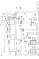
- FIG. 1 is a schematic configuration diagram of a printing apparatus S according to the first embodiment.
- the printing apparatus S according to the first embodiment is a charge control type inkjet printer, and includes an inkjet head 10 and a printing apparatus main body 20, and ejects ink droplets 15 from the inkjet head 10 (nozzles 11).
- the print pattern (the temperature indicating body 110) can be printed on the printing object 100.
- the print pattern printed on the printing object 100 by the printing apparatus S according to the first embodiment is not limited to characters, and may be marks, figures, and the like.
- the printing object 100 is temperature-controlled, and the printing device S and the printing object 100 are arranged in a temperature adjustment space R in which the temperature and humidity are adjusted by an indoor temperature adjustment device (not shown). Has been. In the following description, it is assumed that the temperature adjustment space R is adjusted to the temperature T 0 .
- the inkjet head 10 includes a nozzle 11, a charging electrode 12, a deflection electrode 13, and a gutter 14.
- the printing apparatus main body 20 includes a main container 21, an ink supply path 22, an ink recovery path 26, a first ink container 31A, a first temperature adjustment mechanism 32A, a first heat insulating wall 33A, and a first ink supply path.
- the ink supply path 22 is provided with a supply pump 23, an adjustment valve 24, and an on-off valve 25.
- the ink recovery path 26 is provided with a recovery pump 27 and an opening / closing valve 28.
- An opening / closing valve 35A is provided in the first ink supply path 34A.
- An opening / closing valve 35B is provided in the second ink supply path 34B.
- An opening / closing valve 38 is provided in the solvent supply path 37.
- the supply pump 23 and the recovery pump 27 include a liquid feeding part (not shown) that feeds liquid (ink) and an electric motor part (not shown) that drives the liquid feeding part.
- the supply pump 23 and the recovery pump 27 are covered with heat insulating walls 29 and 30 so that heat generated in the electric motor unit is not transmitted to the inside of the printing apparatus main body 20 (main container 21 and the like) and the temperature adjustment space R. Yes.
- the structure has a structure in which the heat of the electric motor part is difficult to transfer to the liquid feeding part.
- the ink fed by the liquid feeding unit has a structure that hardly changes in temperature due to heat generated by the electric motor unit.
- the inside of the heat insulating walls 29 and 30 can be radiated to the outside of the temperature adjustment space R by a cooling means (not shown).
- the heat insulating walls 29 and 30 have been described as covering the entire pump. However, the heat insulating walls 29 and 30 are not limited to this, and the motor part (not shown) is covered with the heat insulating walls 29 and 30 and the liquid feeding part is covered with the heat insulating walls 29 and 30. You may arrange
- Ink accommodated in the main container 21 (“mixed ink” described later) is supplied to the nozzle 11 by the supply pump 23 via the ink supply path 22, and is ejected as ink droplets 15 from the nozzle 11. At this time, the pressure of the ink droplet 15 ejected from the nozzle 11 is adjusted by the supply pump 23 and the adjustment valve 24 provided in the ink supply path 22.
- the ink droplets 15 ejected from the nozzles 11 are charged by the charging electrode 12, and then the flight direction is controlled by the deflection electrode 13, and land on the printing material 100 to form a printing pattern (temperature indicating body 110). .
- Ink drops 15 that are not used for printing are supplemented by the gutter 14.
- the ink captured by the gutter 14 is recovered by the recovery pump 27 into the main container 21 via the ink recovery path 26.
- the first ink container 31A contains first ink described later.
- the first temperature adjustment mechanism 32A is disposed inside the first heat insulation wall 33A together with the first ink container 31A, and adjusts the temperature (temperature increase / decrease) in the first heat insulation wall 33A.
- the temperature of the first ink stored in the ink container 31A can be adjusted.
- the first temperature adjustment mechanism 32A is controlled by the control unit 40. Further, when the temperature is adjusted by the first temperature adjustment mechanism 32A, it is insulated by the first heat insulation wall 33A, and the influence on the temperature inside the printing apparatus main body 20 (main container 21 and the like) and the temperature adjustment space R is sufficient. small.
- the first ink supply path 34 ⁇ / b> A can supply the first ink stored in the first ink container 31 ⁇ / b> A to the main container 21.
- the second ink container 31B contains second ink described later.
- the second temperature adjusting mechanism 32B is disposed inside the second heat insulating wall 33B together with the second ink container 31B, and adjusts the temperature in the second heat insulating wall 33B (temperature increase / decrease).
- the temperature of the second ink stored in the ink container 31B can be adjusted.
- the second temperature adjustment mechanism 32B is controlled by the control unit 40. Further, when the temperature is adjusted by the second temperature adjustment mechanism 32B, it is insulated by the second heat insulation wall 33B, and the influence on the temperature inside the printing apparatus main body 20 (main container 21 and the like) and the temperature adjustment space R is sufficient. small.
- the second ink supply path 34 ⁇ / b> B can supply the second ink contained in the second ink container 31 ⁇ / b> B to the main container 21.
- the printing apparatus S can independently adjust the temperature of the first ink and the second ink, and the temperature-adjusted first ink and the temperature-adjusted second ink are stored in the main container 21.
- the mixed ink stored in the main container 21 and the mixed ink circulating in the ink supply path 22, the nozzle 11, the gutter 14, and the ink recovery path 26 are heated in the temperature adjustment space R by an indoor temperature adjustment device (not shown). By adjusting, the temperature is adjusted to a predetermined temperature.
- the solvent container 36 contains a solvent.
- the solvent supply path 37 can supply the solvent contained in the solvent container 36 to the main container 21.
- the main container 21 is provided with a viscosity detection device (not shown) for detecting the viscosity of the stored ink, and when the viscosity of the ink becomes higher than a specified value due to volatilization of the solvent, A solvent is supplied to the main container 21.
- the main container 21 is provided with a viscosity detection device (not shown) that stirs the contained ink, and the ink and the solvent can be stirred and mixed.
- the control unit 40 includes a charging electrode 12, a deflection electrode 13, a first temperature adjustment mechanism 32A, a second temperature adjustment mechanism 32B, a supply pump 23, an adjustment valve 24, a recovery pump 27, an on-off valve 25, By controlling 28, 35A, 35B, and 38, the entire printing apparatus S according to the first embodiment can be controlled.
- the first ink in the first ink container 31A is an ink that reversibly changes color (developed / decolored) due to a temperature change, and a temperature at which decolorization starts when the temperature rises (hereinafter, “first decolorization start temperature”).
- first decolorization start temperature a temperature at which decolorization starts when the temperature rises
- second ink in the second ink container 31B is an ink that reversibly changes color (developed / decolored) due to a temperature change.
- second decolorization start The temperature at which decolorization starts when the temperature rises. This is an ink that exhibits a hysteresis discoloration phenomenon that differs from T a2 and temperature at which color development starts when temperature falls (hereinafter referred to as “second color development start temperature”) T d2 .
- the combination of the first ink and the second ink has a first color erasing start temperature T a1 , a first color development start temperature T d1 , a second color erasure start temperature T a2 , and a second color development start temperature T d2.
- An ink combination that satisfies the relationship “T d1 ⁇ T d2 ⁇ T a1 ⁇ T a2 ” is selected.
- the temperature indicating body 110 made of the first ink and the second ink has a deviation from the second color development start temperature T d2 or lower and a deviation from the first color erasing start temperature T a1 or higher. Detect. In other words, the temperature indicator 110 made of the first ink and the second ink determines whether or not the temperature range from the second color development start temperature T d2 to the first color erasing start temperature T a1 has deviated. it can.
- the management temperature range of the temperature indicator 110 can be set.
- FIG. 2 is a transition diagram showing the transition of the color change of the temperature indicator 110 due to the temperature change.
- S0 to S33 indicate the color state of the temperature indicating body 110
- the developed color of the first ink is indicated by left-down hatching
- the developed color of the second ink is indicated by shaded dots.
- the transition by temperature rising is shown by a solid line arrow
- the transition by temperature reduction is shown by a broken line arrow.
- the alternate long and short dash lines indicate the boundaries of the temperatures (T d1 , T d2 , T a1 , T a2 ), and the higher the temperature is on the right side of FIG.
- the initial temperature T 0 of the temperature indicator 110 is “T d2 ⁇ T 0 ⁇ T a1 ”, and the first ink is developed and the second ink is decolored (initial state S0).
- the second ink is developed (S12).
- the first ink is erased before the second ink is erased.
- S13, S23, S33 In order to develop the first ink again from this state, it is necessary to lower the temperature to the first color development start temperature T d1 or lower.
- the second ink develops before the color development. (S32, S31, S21, S11).
- the first ink is decolored (S32).
- the second ink develops before the first ink is developed. (S31, S21, S11).
- the first ink is erased before the second ink is erased. It will be colored (S12, S13, S23, S33).
- the temperature indicator 110 can detect a deviation from the management temperature range.
- FIG. 3 is a flowchart showing ink pre-processing in the printing apparatus S according to the first embodiment.
- step S101 the control unit 40 controls the first temperature adjustment mechanism 32A to lower (cool) the inside of the first heat insulating wall 33A. Specifically, the temperature of the first ink stored in the first ink container 31A is set to be equal to or lower than the first color development start temperature Td1 . Thereby, the first ink starts color development.
- step S102 the control unit 40 determines whether or not the first ink has been developed. For example, when the temperature of the first ink is set to be equal to or lower than the first color development start temperature T d1 and a predetermined time has elapsed, it is determined that the color development of the first ink has been completed. When it is determined that the color development of the first ink has not ended (No in S102), the process of the control unit 40 repeats Step S102. If it is determined that the color development of the first ink has been completed (S102: Yes), the process of the control unit 40 proceeds to step S103.
- step S103 the control unit 40 controls the first temperature adjusting mechanism 32A, the inside of the first insulating wall 33A and the initial temperature T 0.
- the temperature of the first ink stored in the first ink container 31A is set as the initial temperature T 0 .
- the first decoloring start temperature Ta1 is not exceeded.
- step S104 the control unit 40 determines the temperature of the first ink contained in the first ink container 31A is whether the initial temperature T 0. When it is determined that the temperature of the first ink is not the initial temperature T 0 (No in S104), the process of the control unit 40 repeats Step S104. When it is determined that the temperature of the first ink is the initial temperature T 0 (S104, Yes), the process of the control unit 40 proceeds to step S109.
- control part 40 controls the 2nd temperature regulation mechanism 32B, and raises the temperature of the inside of the 2nd heat insulation wall 33B (heating). Specifically, the temperature of the second ink stored in the second ink container 31B is set to the second decoloring start temperature Ta2 or higher. As a result, the second ink starts decoloring.
- step S106 the control unit 40 determines whether or not the decoloring of the second ink has ended. For example, when the temperature of the second ink is set to the second decolorization start temperature Ta2 or more and a predetermined time has elapsed, it is determined that the decoloration of the second ink has been completed. When it is determined that the decoloring of the second ink has not been completed (No in S106), the process of the control unit 40 repeats Step S106. When it is determined that the decoloring of the second ink has ended (S106, Yes), the process of the control unit 40 proceeds to step S107.
- step S107 the control unit 40 controls the second temperature adjusting mechanism 32B to set the inside of the second heat insulating wall 33B to the initial temperature T 0 . That is, the temperature of the second ink stored in the second ink container 31B is set as the initial temperature T 0 .
- the second color development start temperature T d2 is not exceeded.
- step S108 the control unit 40 determines the temperature of the second ink accommodated in the second ink container 31B is whether or not the initial temperature T 0.
- the process of the control unit 40 repeats Step S108.
- the process of the control unit 40 proceeds to step S109.
- processing shown in steps S101 to S104 and the processing shown in steps S105 to S108 may be performed in parallel as shown in FIG. Processing may be performed.
- the control unit 40 performs the process of step S109 after both the process illustrated in step S104 and the process illustrated in step S108 are completed.
- step S109 the control unit 40 controls the opening / closing valve 35A to open the first ink supply path 34A, supply the first ink in the first ink container 31A to the main container 21, and control the opening / closing valve 35B.
- the second ink supply path 34B is opened, and the second ink in the second ink container 31B is supplied to the main container 21.
- the supply of the first ink from the first ink container 31A to the main container 21 may be performed by a pump (not shown), or may be performed by a pressure difference or a height difference.
- the supply of the second ink from the second ink container 31B to the main container 21 is the same.
- the printing apparatus S As described above, the printing apparatus S according to the first embodiment, the first ink of the initial temperature T 0 and the color developing state, and a second ink of the initial temperature T 0 and decolorized state, mixed with the main container 21 By doing so, it is possible to make the mixed ink in the developed state only in the first temperature T 0 and the first ink. And the printing apparatus S which concerns on 1st Embodiment prints a printing pattern (temperature indicator 110) on the to-be-printed material 100 by ejecting the mixed ink of this state as the ink droplet 15 from the inkjet head 10 (nozzle 11). can do.
- a printing pattern temperature indicator 110
- the print pattern printed by the printing apparatus S according to the first embodiment returns to the initial state when it deviates from the management temperature range from the second color development start temperature T d2 to the first color erasing start temperature Ta1. I can't do that. Thereby, the temperature indicator 110 can detect a deviation from the management temperature range.
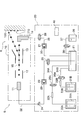
- FIG. 4 is a schematic configuration diagram of a printing apparatus SA according to the second embodiment.
- an indoor temperature adjusting device (not shown) adjusts the temperature of the temperature adjustment space R, so that the mixed ink stored in the main container 21 and the inside of the printing apparatus S (ink supply) The temperature of the mixed ink circulating through the passage 22, the nozzle 11, the gutter 14, and the ink recovery passage 26) is adjusted to a predetermined temperature (initial temperature T 0 ).
- the printing apparatus SA according to the second embodiment includes an internal temperature adjustment mechanism 39. A range in which the internal temperature adjustment mechanism 39 adjusts the temperature is indicated by a broken line 39a.
- the internal temperature adjustment mechanism 39 sets the temperature of the mixed ink stored in the main container 21 and the temperature of the mixed ink circulating through the inside of the printing apparatus SA (the ink supply path 22, the nozzle 11, the gutter 14, and the ink recovery path 26). (The initial temperature T 0 ). In other words, the internal temperature adjustment mechanism 39 performs temperature management so that the temperature is higher than the second color development start temperature T d2 and lower than the first color erasing start temperature Ta1 . Accordingly, the printing apparatus SA according to the second embodiment can suitably manage the temperature of the mixed ink before printing.
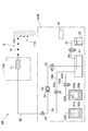
- FIG. 5 is a schematic diagram of a configuration of the printing apparatus SB according to the third embodiment.
- the printing apparatus SB according to the first embodiment is a circulation type (charging control type) ink jet printer.
- the printing apparatus SB according to the third embodiment is a DOD (Drop On Demand) type inkjet printer that ejects ink droplets 15 from the nozzles 11 during printing, and includes an inkjet head 10B and a printing apparatus body 20B. And.
- DOD Drop On Demand
- the inkjet head 10 ⁇ / b> B includes a nozzle 11.
- the printer main body 20B includes a main container 21, an ink supply path 22, a first ink container 31A, a first temperature adjustment mechanism 32A, a first heat insulating wall 33A, a first ink supply path 34A, and a second ink.
- a container 31B, a second temperature adjusting mechanism 32B, a second heat insulating wall 33B, a second ink supply path 34B, a solvent container 36, a solvent supply path 37, and a control unit 40 are provided.
- the ink supply path 22 is provided with a supply pump 23, an adjustment valve 24, and an on-off valve 25.
- An opening / closing valve 35A is provided in the first ink supply path 34A.
- An opening / closing valve 35B is provided in the second ink supply path 34B.
- An opening / closing valve 38 is provided in the solvent supply path 37.
- the volume of a piezo element (piezoelectric element) provided in the nozzle 11 is changed by energization, or the solenoid valve provided in the nozzle 11 is opened and closed by energization.
- ejection / stop of the ink droplet 15 is controlled.
- the printing apparatus SB according to the third embodiment of the DOD type is similar to the printing apparatus S according to the first embodiment of the circulation type (charging control type), and has the initial temperature T 0 and the first color in the developed state.
- the printing apparatus SB according to the third embodiment prints a print pattern (the temperature indicating body 110) on the printing object 100 by ejecting the mixed ink in this state as ink droplets 15 from the inkjet head 10 (nozzle 11). can do.
- the print pattern printed by the printing apparatus SB according to the third embodiment returns to the initial state when it deviates from the management temperature range from the second color development start temperature T d2 to the first color erasing start temperature Ta1. I can't do that. Thereby, the temperature indicator 110 can detect a deviation from the management temperature range.
- the printing apparatus SB may include an internal temperature adjustment mechanism (not shown).
- the internal temperature adjusting mechanism can adjust the temperature of the mixed ink stored in the main container 21 and the mixed ink supplied from the ink supply path 22 to the nozzle 11 to a predetermined temperature (initial temperature T 0 ). Thereby, the temperature of the mixed ink before printing can be suitably managed.
- FIG. 6 is a schematic configuration diagram of a printing apparatus SC according to the fourth embodiment.
- the printing device SC is a DOD type ink jet printer that ejects first ink and second ink from separate nozzles 11A and 11B, and includes an ink jet head 10C and a printing device main body 20C. Yes.
- the inkjet head 10C includes nozzles 11A and 11B.
- the printer main body 20C includes a first ink supply path 22A, a first ink container 31A, a first temperature adjustment mechanism 32A, a first heat insulation wall 33A, a second ink supply path 22B, and a second ink container 31B.
- the 2nd temperature regulation mechanism 32B, the 2nd heat insulation wall 33B, and the control part 40 are provided.
- the first ink supply path 22A is provided with a supply pump 23A and a regulating valve 24A.
- a supply pump 23B and a regulating valve 24B are provided in the second ink supply path 22B.
- the first ink stored in the first ink container 31A is in a developed state with an initial temperature T 0 by the processing shown in steps S101 to S104 in FIG. 3, and is connected to the nozzles via the first ink supply path 22A. 11A, and the first ink droplet 15A is ejected from the nozzle 11A.
- the second ink stored in the second ink container 31B is in the initial temperature T 0 and decolored by the processing shown in Step S105 to Step S108 in FIG. 3, and passes through the second ink supply path 22B.
- the second ink droplet 15B is discharged from the nozzle 11B.
- the ink droplets 15A and 15B ejected from the nozzles 11A and 11B land on the printed material 100 to form a print pattern (the temperature indicating body 110).
- the printing apparatus SC according to the fourth embodiment having the plurality of nozzles 11A and 11B like the printing apparatuses S to SB according to the first to third embodiments, has the second color development start temperature T d2. can be from the print printing pattern can not return to the initial state when departing from the control temperature range up first decoloring starting temperature T a1 (the temperature indicating member 110) to the printing object 100.
- the printing apparatus SC if the landing positions of the ink droplets 15A and the landing positions of the ink droplets 15B are greatly separated, a printing pattern (temperature indicating body 110) deviating from the management temperature range is obtained. Even in this case, only the print pattern of the first ink is cooled to the developed state, and only the print pattern of the second ink is heated to the decolored state, so that the print pattern (the temperature indicating body 110) is in the initial state ( It is possible to return to the state where only the first ink is developed.
- the landing position of the ink droplet 15A and the landing position of the ink droplet 15B are the same position.
- the print pattern of the first ink and the print pattern of the second ink partially intersect.
- printing may be performed so that the first ink printing pattern and the second ink printing pattern are sufficiently close to each other.
- the forgery which returns the printing pattern (temperature indicator 110) which deviated from the management temperature range to an initial state can be prevented.
- the first ink print pattern and the second ink print pattern are sufficiently close when the print pattern of only one ink is heated or cooled, the other print pattern is also heated or cooled, so This means that the color state is close to changing.
- first ink and the second ink may be ejected at the same time, and the first ink and the second ink may be mixed on the printing surface of the substrate 100, and the first ink may be ejected to print the substrate 100.
- the second ink may be ejected from the first ink printing pattern to form the second ink printing pattern on the printing surface of the substrate 100. Further, the order of discharging the first ink and the second ink may be reversed.
- the printing apparatus SC according to the fourth embodiment may include an internal temperature adjustment mechanism (not shown). Thereby, the temperature of the 1st ink and 2nd ink before printing can be managed suitably.
- the printing apparatus SC according to the fourth embodiment has been described as a DOD type ink jet printer, it may be applied to a circulation type (charge control type) ink jet printer including a plurality of ink jet heads.
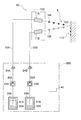
- FIG. 7 is a schematic configuration diagram of a writing apparatus SD according to the fifth embodiment.
- the writing apparatus SD includes a first ink container 31A that stores first ink, a second ink container 31B that stores second ink, a main container 21, a casing 60, and a heat insulating wall 61. , Observation windows 62A and 62B, a heat conducting member 63, and a pen tip portion 64 are provided.
- the first ink stored in the first ink container 31 ⁇ / b> A is supplied to the main container 21.
- the second ink stored in the second ink container 31 ⁇ / b> B is supplied to the main container 21.
- the supplied first ink and second ink are mixed in the main container 21 to become mixed ink.
- the mixed ink in the main container 21 is supplied to the pen tip portion 64. Thereby, the writing device SD according to the fifth embodiment can write with the mixed ink.
- the heat insulating wall 61 is provided between the first ink container 31 ⁇ / b> A and the second ink container 31 ⁇ / b> B disposed inside the housing 60.
- the observation window 62A is provided on the side surface of the housing 60 so that the developed / decolored state of the first ink stored in the first ink container 31A can be observed from the outside.
- the observation window 62B is provided on the side surface of the housing 60 so that the developed / decolored state of the second ink stored in the second ink container 31B can be observed from the outside.
- the heat conducting member 63 is provided on the side surface of the housing 60 and is provided so as to be able to conduct heat with the second ink container 31B.
- the first ink and the second ink used in the writing apparatus SD according to the fifth embodiment are the same as those used in the printing apparatus S according to the first embodiment, and redundant description is omitted.
- the entire writing apparatus SD is cooled to the first color development start temperature T d1 or lower.
- the writing device SD is cooled in a freezer.
- the first ink and the second ink are in a developed state.
- the entire writing device SD is set to the initial temperature T 0 (“T d2 ⁇ T 0 ⁇ T a1 ”).
- T d2 ⁇ T 0 ⁇ T a1 ” the writing device SD is taken out from the freezer and left in a room where the writing device SD performs writing work.
- the first ink and the second ink remain in the developed state. By writing in this state, the first ink and the second ink can be written in a developed color.
- heat is supplied from the heat conducting member 63 to heat the second ink in the second ink container 31B to the second decolorization start temperature Ta2 or higher.
- the second ink is heated by frictional heat generated by rubbing the heat conducting member 63.
- the heat insulating wall 61 prevents heat from the heat conducting member 63 and the second ink container 31B from being transmitted to the first ink accommodated in the first ink container 31A. As a result, the first ink remains in the developed state and the second ink is in the decolored state.
- the entire writing device SD is set to the initial temperature T 0 (“T d2 ⁇ T 0 ⁇ T a1 ”).
- T d2 ⁇ T 0 ⁇ T a1 the initial temperature
- the second ink remains in the decolored state.
- the writing apparatus SD can be a writing instrument that writes in different colors. Further, by writing with the first ink in the developed state and the second ink in the decolored state, the written pattern is written from the second developed color start temperature T d2 to the first erased temperature T a1 . When the temperature deviates from the management temperature range, it is impossible to return to the initial state S0 (the state where the first ink is developed and the second ink is decolored). Thereby, this writing pattern can detect the deviation from a management temperature range similarly to the temperature indicator 110 of 1st Embodiment.
- Examples of ink materials that have reversibility of color change and exhibit a hysteresis discoloration phenomenon in which the color development start temperature and the color erasure start temperature are different include leuco dyes that are electron donating compounds and color developers that are electron accepting compounds. And a composition comprising a decolorizer for controlling the temperature range of hysteresis.
- Leuco dyes are usually colorless or light in color, but are colored by contact with a developer.
- the decolorizer can decolorize the colored leuco dye when heated in the presence of a leuco dye and a developer.
- the temperature range of hysteresis greatly depends on the melting point and freezing point of the decolorizer.
- T a1 ⁇ T d1 representing the hysteresis width of the first ink is T a1 ⁇ T d1 ⁇ 6 ° C.
- T a2 ⁇ T d2 representing the following must satisfy T a2 ⁇ T d2 ⁇ 6 ° C.
- the temperature range to be managed is often about 5 ° C to 15 ° C. Therefore, it is preferable that the color developing temperature T d2 of the second ink and the color erasing temperature T a1 of the first ink satisfy the relationship of 5 ⁇ T a1 ⁇ T d2 ⁇ 15 ° C.
- the leuco dye is composed of an electron donating compound, and conventionally known dyes for pressure-sensitive copying paper and heat-sensitive recording paper can be used.
- conventionally known dyes for pressure-sensitive copying paper and heat-sensitive recording paper can be used.
- triphenylmethane phthalide, fluoran, phenothiazine, indolylphthalide, leucooramine, spiropyran, rhodamine lactam, triphenylmethane, triazene, spirophthalanthanthene, naphtholactam Examples include azomethine series.
- leuco dyes include 9- (N-ethyl-N-isopentylamino) spiro [benzo [a] xanthene-12,3′-phthalide], 2-methyl-6- (Np-tolyl).
- a dye exhibiting a color other than black particularly from the viewpoint of visibility
- the first ink and the second ink are preferably different colors.
- 9- (N-ethyl-N-isopentylamino) spiro [benzo [a] xanthene-12,3′-phthalide] is used as the leuco dye of the first ink
- 3- ( 4-Diethylamino-2-methylphenyl) -3- (1-ethyl-2-methylindol-3-yl) -4-azaphthalide is preferred.
- the combination of the first ink and the second ink is not limited to these, and any combination that exhibits different colors may be used.
- the first ink and the second ink can be used alone or in combination of two or more.
- the electron acceptor developer used in the ink of the present embodiment can be colored by changing the structure of the leuco dye by contacting with the electron donating leuco dye.
- a publicly known developer can be used for heat-sensitive recording paper or pressure-sensitive copying paper.
- Such a developer examples include benzyl 4-hydroxybenzoate, 2,2'-biphenol, 1,1-bis (3-cyclohexyl-4-hydroxyphenyl) cyclohexane, 2,2-bis (3 -Phenols such as -cyclohexyl-4-hydroxyphenyl) propane, bisphenol A, bisphenol F, bis (4-hydroxyphenyl) sulfide, paraoxybenzoic acid ester, gallic acid ester and the like.
- the developer is not limited to these and may be any compound that is an electron acceptor and can change the color of the leuco dye.
- metal salts of carboxylic acid derivatives, salicylic acid and salicylic acid metal salts, sulfonic acids, sulfonates, phosphoric acids, phosphate metal salts, acidic phosphate esters, acidic phosphate metal salts, phosphorous acids, phosphorous acid Metal salts and the like may be used.
- organic color developers such as 2,2'-bisphenol, bisphenol A, gallic acid esters and the like are preferable.
- one or two or more of these developers may be combined, and the color density at the time of coloring of the leuco dye can be adjusted by combining them.
- the amount of the developer used is selected according to the desired color density. For example, it may be selected within a range of about 0.1 to 100 parts by weight with respect to 1 part by weight of the leuco dye.
- the decolorizer in the present embodiment is a compound that can dissociate the bond between the leuco dye and the developer, and is a compound that can control the color temperature between the leuco dye and the developer.
- the decolorizer is solidified in a phase-separated state.
- the decolorizer is melted and a function of releasing the bond between the leuco dye and the developer is exhibited.
- the coloration and decoloring temperature of the leuco dye used in the ink of this embodiment depends on the freezing point and melting point of the decolorizer.
- the melting point or the temperature of the freezing point depends on the target temperature management range.
- fatty acid ester compounds such as isopropyl myristate, isopropyl palmitate, tricaprylin, tricaprin, trilaurin, and trimyristin, and these compounds are included from the viewpoint of compatibility with leuco dyes and developers. Is preferred.
- These decolorizers may be used alone or in combination of two or more. In this case, the freezing point and the melting point can be adjusted. Of course, it is not limited to these compounds, For example, other ester, alcohols, ethers, ketones, amides, azomethines, fatty acids, hydrocarbons etc. can be mentioned.
- the combination of the leuco dye, the developer and the color erasing agent used in the ink of the present embodiment can be used by being uniformly dispersed in ink, paint, synthetic resin, etc., similarly to ordinary dyes and pigments.
- the microcapsules made of a resin film are independently encapsulated.
- the mixed ink obtained by mixing the first ink and the second ink is used for printing or the like in the first embodiment, the leuco dye, the developer, and the color erasing agent of the first ink and the second ink are mixed. In order to avoid this, it is desirable to microencapsulate.
- microencapsulating as described above, environmental resistance to humidity and the like of the composition is improved, and storage stability, discoloration characteristics, and the like can be achieved.
- Various known techniques can be applied to the microencapsulation. For example, an emulsion polymerization method, a suspension polymerization method, a coacervation method, an interfacial polymerization method, a spray drying method and the like can be mentioned, but the invention is not limited to these. Two or more different methods may be combined.
- Resin coatings used for microcapsules include urea resin coatings composed of polyamines and carbonyl compounds, melamine / formalin prepolymers, methylol melamine prepolymers, melamine resin coatings composed of methylated melamine prepolymers, polyisocyanates and polyol compounds.
- Urethane resin coatings amide resin coatings composed of polybasic acid chlorides and polyvalent amines, vinyl-based resin coatings composed of various monomers such as vinyl acetate, styrene, (meth) acrylic acid esters, acrylonitrile, and vinyl chloride.
- urea resin coatings composed of polyamines and carbonyl compounds
- melamine / formalin prepolymers methylol melamine prepolymers
- melamine resin coatings composed of methylated melamine prepolymers
- polyisocyanates polyol compounds.
- Urethane resin coatings amide resin coatings composed of polybasic acid chlorides and poly
- the diameter of the microcapsule is preferably in the range of about 0.1 to 100 ⁇ m, because apparatus compatibility, storage stability, and the like are problems. More preferably, the range of 0.1 to 1 ⁇ m is good.
- the ink solution contains a resin, a colorant, an additive having a polydimethylsiloxane chain, an additive having an alkoxysilane group, a solvent, and the like, and these materials are stirred with an overhead stirrer or the like to dissolve or disperse each other. Is formed.
- a conductive agent described later is also added.
- the first ink solution and the second ink solution in which the first ink and the second ink are dispersed in the solvent are required.
- the resistance of the ink solution is high, the ink particles do not fly straight but tend to bend at the ink ejection portion in the charge control type ink jet printer. Therefore, the resistance needs to be approximately 2000 ⁇ cm or less.
- the composition of the ink is mainly an organic solvent, resin, and pigment mainly composed of 2-butanone and ethanol.
- the ink Since these have low electrical conductivity, if the ink is constituted only by this, the resistance is as large as about 5000 to tens of thousands ⁇ cm, and it becomes difficult to perform desired printing with the charge control type ink jet printer. Therefore, it is necessary to add a conductive agent. It is preferable to use a complex as the conductive agent. The conductive agent must be dissolved in the solvent used, and it is also important that the color tone is not affected. In general, a conductive agent having a salt structure is used. It is presumed that this has high electrical conductivity because it has a charge bias in the molecule.
- the conductive agent has a salt structure and the cation has a tetraalkylammonium ion structure.
- the alkyl chain may be linear or branched, and the greater the carbon number, the better the solubility in the solvent. However, the smaller the carbon number, the lower the resistance with a small addition rate.
- the actual carbon number when used in ink is about 2-8.
- hexafluorophosphate ion, tetrafluoroborate ion, and the like are preferable because of high solubility in a solvent.
- perchlorate ions are also highly soluble, they are explosive and are not practical to use in ink.
- chlorine, bromine and iodine ions may be mentioned, but these are not preferable since they tend to corrode when they come into contact with metals such as iron and stainless steel.
- preferred conductive agents are tetraethylammonium hexafluorophosphate, tetrapropylammonium hexafluorophosphate, tetrabutylammonium hexafluorophosphate, tetrapentylammonium hexafluorophosphate, tetrahexylammonium hexafluorophosphate, tetraoctylammonium.
- Hexafluorophosphate tetraethylammonium tetrafluoroborate, tetrapropylammonium tetrafluoroborate, tetrabutylammonium tetrafluoroborate, tetrapentylammonium tetrafluoroborate, tetrahexylammonium tetrafluoroborate, tetraoctylammonium tetrafluoroborate, etc. .
- the printing apparatuses S to SC according to the first to fourth embodiments have been described as charging control type (circulation type) ink jet printers or DOD type ink jet printers, but are not limited thereto.
- the present invention may be applied to a stamping type (stamp, coder) printing apparatus.
- the printing apparatus S includes two temperature adjustment mechanisms, a first temperature adjustment mechanism 32A that adjusts the temperature of the first ink, and a second temperature adjustment mechanism 32B that adjusts the temperature of the second ink. Although described as comprising, it is not limited to this. A configuration including only one of the first temperature adjustment mechanism 32A and the second temperature adjustment mechanism 32B may be employed. In this case, for example, in a configuration including only the first temperature adjustment mechanism 32A, the second ink may be accommodated in the second ink container 31B in a state where the color is previously erased.
- the second heat insulating wall 33B is also removed from the configuration, and the temperature of the temperature adjustment space R is adjusted by an indoor temperature adjustment device (not shown), so that the second ink is also adjusted to a predetermined temperature (initial temperature T 0 ). Is done.
- the printing apparatus SA according to the second embodiment, the printing apparatus SB according to the third embodiment, and the printing apparatus SC according to the fourth embodiment may be configured similarly.
- the first temperature adjustment mechanism 32A that adjusts the temperature of the first ink is disposed on the first ink container 31A side, and the second temperature adjustment mechanism that adjusts the temperature of the second ink.
- 32B was demonstrated as what is arrange
- FIG. 8 is a schematic diagram of the configuration of the printing apparatus S according to the first modification. As shown in FIG. 8, the first temperature adjustment mechanism 32A may be provided in the first ink supply path 34A (preferably upstream of the on-off valve 35A), and the second temperature adjustment mechanism 32B is provided in the second ink. It may be provided in the supply path 34B (preferably upstream of the on-off valve 35B).
- the first temperature adjustment mechanism 32A includes a temperature lowering unit (not shown) on the upstream side and a temperature adjusting unit (not shown) on the downstream side, and the temperature of the first ink is set to the first in the temperature lowering unit. After the color development start temperature T d1 or less, the temperature of the first ink may be set to the initial temperature T 0 in the temperature adjustment unit.
- the second temperature adjustment mechanism 32B includes a temperature raising unit (not shown) on the upstream side and a temperature adjusting unit (not shown) on the downstream side, and the temperature of the second ink is increased by the temperature raising unit. The temperature of the second ink may be set to the initial temperature T 0 in the temperature adjusting unit after the temperature of the 2 color erasing start temperature Ta 2 or higher.
- the first temperature adjustment mechanism 32A is provided with the first ink supply path 34A (preferably upstream of the on-off valve 35A).
- the second temperature adjustment mechanism 32B may be provided in the second ink supply path 34B (preferably upstream of the on-off valve 35B).
- the first temperature adjustment mechanism 32A may be provided in the ink supply path 22A (preferably upstream of the supply pump 23A).
- the adjustment mechanism 32B may be provided in the ink supply path 22B (preferably upstream of the supply pump 23B).
- the printing apparatus S according to the first embodiment adjusts the temperature of the mixed ink stored in the main container 21 by adjusting the temperature adjustment space R with an indoor temperature adjustment device (not shown) (T d2 ⁇ T 0 ⁇ T a1 ), and the printing apparatus SA according to the second embodiment has the temperature of the mixed ink stored in the main container 21 by the internal temperature adjustment mechanism 39 adjusting the temperature of the inside of the printing apparatus SA.
- the present invention is not limited to the above description (T d2 ⁇ T 0 ⁇ T a1 ).
- FIG. 9 is a schematic diagram of a configuration of the printing apparatus S according to the second modification. As shown in FIG.
- the third temperature adjustment mechanism 42 is disposed inside the heat insulating wall 43 together with the main container 21, and the third temperature adjustment mechanism 42 adjusts the temperature of the mixed ink stored in the main container 21. It may be configured to be able to. Further, the temperature of the mixed ink adjusted by the third temperature adjusting mechanism 42 is adjusted by covering the path (ink supply path 22, ink recovery path 26, etc.) through which the mixed ink flows with, for example, a heat insulating material (not shown). It is preferable to be configured to keep. Further, the printing device SB according to the third embodiment may be configured similarly.
Landscapes
- Engineering & Computer Science (AREA)
- Chemical & Material Sciences (AREA)
- General Physics & Mathematics (AREA)
- Physics & Mathematics (AREA)
- Quality & Reliability (AREA)
- Life Sciences & Earth Sciences (AREA)
- Mechanical Engineering (AREA)
- Materials Engineering (AREA)
- Wood Science & Technology (AREA)
- Organic Chemistry (AREA)
- Ink Jet (AREA)
- Remote Sensing (AREA)
- Automation & Control Theory (AREA)
Priority Applications (4)
| Application Number | Priority Date | Filing Date | Title |
|---|---|---|---|
| EP17798984.5A EP3459743B1 (en) | 2016-05-18 | 2017-03-08 | Printing device and method for controlling printing device |
| JP2018518116A JP6664472B2 (ja) | 2016-05-18 | 2017-03-08 | 印字装置および印字装置の制御方法 |
| CN201780030492.0A CN109153266B (zh) | 2016-05-18 | 2017-03-08 | 打印装置、打印装置的控制方法和书写装置 |
| US16/301,925 US10894425B2 (en) | 2016-05-18 | 2017-03-08 | Printing device, printing device control method and writing device |
Applications Claiming Priority (2)
| Application Number | Priority Date | Filing Date | Title |
|---|---|---|---|
| JP2016099627 | 2016-05-18 | ||
| JP2016-099627 | 2016-05-18 |
Publications (1)
| Publication Number | Publication Date |
|---|---|
| WO2017199549A1 true WO2017199549A1 (ja) | 2017-11-23 |
Family
ID=60325887
Family Applications (1)
| Application Number | Title | Priority Date | Filing Date |
|---|---|---|---|
| PCT/JP2017/009321 WO2017199549A1 (ja) | 2016-05-18 | 2017-03-08 | 印字装置、印字装置の制御方法、および、筆記装置 |
Country Status (5)
| Country | Link |
|---|---|
| US (1) | US10894425B2 (zh) |
| EP (1) | EP3459743B1 (zh) |
| JP (1) | JP6664472B2 (zh) |
| CN (1) | CN109153266B (zh) |
| WO (1) | WO2017199549A1 (zh) |
Cited By (2)
| Publication number | Priority date | Publication date | Assignee | Title |
|---|---|---|---|---|
| JP2019195967A (ja) * | 2018-05-10 | 2019-11-14 | 株式会社Screenホールディングス | インクジェット印刷装置 |
| EP3556565B1 (en) * | 2018-04-19 | 2022-10-12 | Société BIC | Device that produces color on demand |
Families Citing this family (1)
| Publication number | Priority date | Publication date | Assignee | Title |
|---|---|---|---|---|
| JP7162885B2 (ja) * | 2019-03-15 | 2022-10-31 | 株式会社ミヤコシ | インクジェット印字装置 |
Citations (14)
| Publication number | Priority date | Publication date | Assignee | Title |
|---|---|---|---|---|
| JPS52169430U (zh) * | 1976-06-15 | 1977-12-22 | ||
| JPH0738931U (ja) * | 1983-10-21 | 1995-07-14 | 大日本印刷株式会社 | 感温性印刷体 |
| JP2003214961A (ja) * | 2002-01-22 | 2003-07-30 | Daiwa Can Co Ltd | 示温インクによる熱履歴識別方法 |
| JP2003220714A (ja) * | 2002-01-31 | 2003-08-05 | Konica Corp | インクジェットプリンタ |
| JP2003315167A (ja) * | 2002-04-24 | 2003-11-06 | Pilot Ink Co Ltd | 温度履歴検知用不可逆的熱変色表示体 |
| JP2005271365A (ja) * | 2004-03-24 | 2005-10-06 | Mitsubishi Pencil Co Ltd | 筆記具 |
| JP2007001128A (ja) * | 2005-06-23 | 2007-01-11 | Olympus Corp | インクジェットヘッド |
| JP2007106979A (ja) * | 2005-09-13 | 2007-04-26 | Ricoh Co Ltd | インクジェット熱記録用インク組成物 |
| JP2009503455A (ja) * | 2005-07-27 | 2009-01-29 | シーアールシー スマートプリント ピーティーワイ エルティーディー | 時間−温度インジケータ |
| JP2009204573A (ja) * | 2008-02-29 | 2009-09-10 | Nichiyu Giken Kogyo Co Ltd | 多段階変色温度インジケータ |
| JP2011051094A (ja) * | 2009-08-31 | 2011-03-17 | Pilot Ink Co Ltd | 筆記具セット |
| JP2013233801A (ja) * | 2012-05-04 | 2013-11-21 | Xerox Corp | インラインゲルインク混合のためのシステムおよび方法 |
| US20140118430A1 (en) * | 2011-10-24 | 2014-05-01 | Adam L. Ghozeil | Fluid ejection systems and methods thereof |
| JP2015003453A (ja) * | 2013-06-21 | 2015-01-08 | 株式会社パイロットコーポレーション | 熱変色性筆記具用レフィル |
Family Cites Families (15)
| Publication number | Priority date | Publication date | Assignee | Title |
|---|---|---|---|---|
| EP1083053A1 (en) * | 1999-09-09 | 2001-03-14 | De La Rue Giori S.A. | Inkjet printing device for inks containing a high loading of pigment and inkjet printing process utilizing said device |
| EP1208986A1 (en) * | 2000-11-27 | 2002-05-29 | Océ-Technologies B.V. | Ink jet printing system, ink container and method of preparing the same |
| DE102008011299A1 (de) * | 2008-02-27 | 2009-09-03 | Giesecke & Devrient Gmbh | Wertdokument mit Fälschungssicherung durch thermochrome Anzeige. |
| JP5276902B2 (ja) * | 2008-06-03 | 2013-08-28 | 理想科学工業株式会社 | インクジェットプリンタ及びそのインク検出方法 |
| JP5367629B2 (ja) * | 2010-03-30 | 2013-12-11 | 理想科学工業株式会社 | インクジェットプリンタ |
| JP5417242B2 (ja) * | 2010-04-01 | 2014-02-12 | 理想科学工業株式会社 | インクジェットプリンタ |
| WO2011162152A1 (ja) | 2010-06-23 | 2011-12-29 | コニカミノルタホールディングス株式会社 | インクジェット記録装置、インク供給方法、電源遮断方法及びインクジェット記録装置の温度調節部遮断方法 |
| FR2986324A1 (fr) * | 2012-01-30 | 2013-08-02 | Gem Innov | Indicateur de respect d'une plage de temperature |
| JP2014004795A (ja) * | 2012-06-27 | 2014-01-16 | Pilot Corporation | 可逆熱変色性印刷物 |
| JP2014047305A (ja) * | 2012-08-31 | 2014-03-17 | Fujifilm Corp | インクパック |
| JP2014079885A (ja) * | 2012-10-12 | 2014-05-08 | Toshiba Corp | インクジェット印字装置及びそのインク循環制御方法 |
| JP6284833B2 (ja) | 2014-06-23 | 2018-02-28 | 株式会社日立産機システム | マーキング、マーキング方法、およびインクジェットプリンタ |
| WO2016024455A1 (ja) * | 2014-08-11 | 2016-02-18 | コニカミノルタ株式会社 | インクジェット記録装置及びインクの温度制御方法 |
| JP6743402B2 (ja) * | 2016-02-12 | 2020-08-19 | 富士ゼロックス株式会社 | 液体供給装置及び液滴吐出装置 |
| JP7022516B2 (ja) * | 2017-04-17 | 2022-02-18 | 株式会社日立産機システム | 温度検知材料、それを用いた温度検知インク、温度インジケータ、および物品管理システム |
-
2017
- 2017-03-08 EP EP17798984.5A patent/EP3459743B1/en active Active
- 2017-03-08 US US16/301,925 patent/US10894425B2/en active Active
- 2017-03-08 CN CN201780030492.0A patent/CN109153266B/zh active Active
- 2017-03-08 JP JP2018518116A patent/JP6664472B2/ja active Active
- 2017-03-08 WO PCT/JP2017/009321 patent/WO2017199549A1/ja unknown
Patent Citations (14)
| Publication number | Priority date | Publication date | Assignee | Title |
|---|---|---|---|---|
| JPS52169430U (zh) * | 1976-06-15 | 1977-12-22 | ||
| JPH0738931U (ja) * | 1983-10-21 | 1995-07-14 | 大日本印刷株式会社 | 感温性印刷体 |
| JP2003214961A (ja) * | 2002-01-22 | 2003-07-30 | Daiwa Can Co Ltd | 示温インクによる熱履歴識別方法 |
| JP2003220714A (ja) * | 2002-01-31 | 2003-08-05 | Konica Corp | インクジェットプリンタ |
| JP2003315167A (ja) * | 2002-04-24 | 2003-11-06 | Pilot Ink Co Ltd | 温度履歴検知用不可逆的熱変色表示体 |
| JP2005271365A (ja) * | 2004-03-24 | 2005-10-06 | Mitsubishi Pencil Co Ltd | 筆記具 |
| JP2007001128A (ja) * | 2005-06-23 | 2007-01-11 | Olympus Corp | インクジェットヘッド |
| JP2009503455A (ja) * | 2005-07-27 | 2009-01-29 | シーアールシー スマートプリント ピーティーワイ エルティーディー | 時間−温度インジケータ |
| JP2007106979A (ja) * | 2005-09-13 | 2007-04-26 | Ricoh Co Ltd | インクジェット熱記録用インク組成物 |
| JP2009204573A (ja) * | 2008-02-29 | 2009-09-10 | Nichiyu Giken Kogyo Co Ltd | 多段階変色温度インジケータ |
| JP2011051094A (ja) * | 2009-08-31 | 2011-03-17 | Pilot Ink Co Ltd | 筆記具セット |
| US20140118430A1 (en) * | 2011-10-24 | 2014-05-01 | Adam L. Ghozeil | Fluid ejection systems and methods thereof |
| JP2013233801A (ja) * | 2012-05-04 | 2013-11-21 | Xerox Corp | インラインゲルインク混合のためのシステムおよび方法 |
| JP2015003453A (ja) * | 2013-06-21 | 2015-01-08 | 株式会社パイロットコーポレーション | 熱変色性筆記具用レフィル |
Non-Patent Citations (1)
| Title |
|---|
| See also references of EP3459743A4 * |
Cited By (3)
| Publication number | Priority date | Publication date | Assignee | Title |
|---|---|---|---|---|
| EP3556565B1 (en) * | 2018-04-19 | 2022-10-12 | Société BIC | Device that produces color on demand |
| JP2019195967A (ja) * | 2018-05-10 | 2019-11-14 | 株式会社Screenホールディングス | インクジェット印刷装置 |
| JP7034005B2 (ja) | 2018-05-10 | 2022-03-11 | 株式会社Screenホールディングス | インクジェット印刷装置 |
Also Published As
| Publication number | Publication date |
|---|---|
| JP6664472B2 (ja) | 2020-03-13 |
| US20190286176A1 (en) | 2019-09-19 |
| CN109153266B (zh) | 2020-07-03 |
| US10894425B2 (en) | 2021-01-19 |
| EP3459743B1 (en) | 2024-05-08 |
| EP3459743A4 (en) | 2019-12-25 |
| CN109153266A (zh) | 2019-01-04 |
| EP3459743A1 (en) | 2019-03-27 |
| JPWO2017199549A1 (ja) | 2019-03-07 |
Similar Documents
| Publication | Publication Date | Title |
|---|---|---|
| JP6613371B2 (ja) | 温度履歴表示体及びそれを用いた物品の品質管理方法 | |
| JP6664472B2 (ja) | 印字装置および印字装置の制御方法 | |
| JP6533833B2 (ja) | 温度検知体 | |
| US6010808A (en) | Rewritable thermal recording medium and recording method | |
| WO2018012162A1 (ja) | 印字装置、印字装置の制御方法、および、筆記装置 | |
| US9389210B2 (en) | Thermal distribution display | |
| WO2020158162A1 (ja) | 温度検知ラベルおよび温度検知インク | |
| KR20210066226A (ko) | 감온 변색성 조성물, 이를 포함하는 감온 변색성 마이크로캡슐 및 이를 이용한 시간-온도 지시계 | |
| JP2001041829A (ja) | 示温部材の初期化制御方法、温度管理部材及び温度管理方法 | |
| JP2020008384A5 (zh) | ||
| JP2022087590A (ja) | 不可逆性感熱顕色インクおよびこれを用いた印刷装置 | |
| WO2021059568A1 (ja) | インク、該インクの製造方法、および該インクを用いた温度インジケータ | |
| JP2022144764A (ja) | 画像形成装置 | |
| JPH06305247A (ja) | 可逆的二色感熱記録媒体及び表示媒体、ならびにそれを利用する二色画像の形成方法とその消去方法 | |
| WO2020085358A1 (ja) | インキ用可逆熱変色性マイクロカプセル顔料、およびそれを用いた可逆熱変色性水性インキ組成物 | |
| JP2003237235A (ja) | 多色発色型可逆性感熱記録媒体、その印字・消去方法及び書き換え装置 | |
| JP2020063320A (ja) | インクジェットプリンター用可逆熱変色性水性インキ組成物 | |
| JP2005074984A (ja) | 可逆型感熱記録媒体および画像処理方法 | |
| JPH10250226A (ja) | 書換え型感熱シート | |
| JPH0740659A (ja) | 可逆的感熱記録媒体及びその製造方法 | |
| JP2003096045A (ja) | 新規なカルバミド酸エステル化合物及び該化合物を用いた可逆性感熱記録媒体 | |
| JPH07172051A (ja) | 可逆的感熱記録媒体 | |
| JPH04344287A (ja) | 可逆的熱発色性組成物及び可逆的感熱記録材料 | |
| JPH06320861A (ja) | 可逆的感熱記録媒体の発色記録方法及び記録消去方法 |
Legal Events
| Date | Code | Title | Description |
|---|---|---|---|
| ENP | Entry into the national phase |
Ref document number: 2018518116 Country of ref document: JP Kind code of ref document: A |
|
| NENP | Non-entry into the national phase |
Ref country code: DE |
|
| 121 | Ep: the epo has been informed by wipo that ep was designated in this application |
Ref document number: 17798984 Country of ref document: EP Kind code of ref document: A1 |
|
| ENP | Entry into the national phase |
Ref document number: 2017798984 Country of ref document: EP Effective date: 20181218 |