WO2017195777A1 - 加熱調理器 - Google Patents
加熱調理器 Download PDFInfo
- Publication number
- WO2017195777A1 WO2017195777A1 PCT/JP2017/017542 JP2017017542W WO2017195777A1 WO 2017195777 A1 WO2017195777 A1 WO 2017195777A1 JP 2017017542 W JP2017017542 W JP 2017017542W WO 2017195777 A1 WO2017195777 A1 WO 2017195777A1
- Authority
- WO
- WIPO (PCT)
- Prior art keywords
- plate
- heat
- gas burner
- hole
- meat
- Prior art date
- Legal status (The legal status is an assumption and is not a legal conclusion. Google has not performed a legal analysis and makes no representation as to the accuracy of the status listed.)
- Ceased
Links
Images


Classifications
-
- A—HUMAN NECESSITIES
- A47—FURNITURE; DOMESTIC ARTICLES OR APPLIANCES; COFFEE MILLS; SPICE MILLS; SUCTION CLEANERS IN GENERAL
- A47J—KITCHEN EQUIPMENT; COFFEE MILLS; SPICE MILLS; APPARATUS FOR MAKING BEVERAGES
- A47J37/00—Baking; Roasting; Grilling; Frying
- A47J37/06—Roasters; Grills; Sandwich grills
- A47J37/067—Horizontally disposed broiling griddles
- A47J37/0682—Horizontally disposed broiling griddles gas-heated
-
- A—HUMAN NECESSITIES
- A47—FURNITURE; DOMESTIC ARTICLES OR APPLIANCES; COFFEE MILLS; SPICE MILLS; SUCTION CLEANERS IN GENERAL
- A47J—KITCHEN EQUIPMENT; COFFEE MILLS; SPICE MILLS; APPARATUS FOR MAKING BEVERAGES
- A47J37/00—Baking; Roasting; Grilling; Frying
- A47J37/06—Roasters; Grills; Sandwich grills
-
- A—HUMAN NECESSITIES
- A47—FURNITURE; DOMESTIC ARTICLES OR APPLIANCES; COFFEE MILLS; SPICE MILLS; SUCTION CLEANERS IN GENERAL
- A47J—KITCHEN EQUIPMENT; COFFEE MILLS; SPICE MILLS; APPARATUS FOR MAKING BEVERAGES
- A47J36/00—Parts, details or accessories of cooking-vessels
- A47J36/02—Selection of specific materials, e.g. heavy bottoms with copper inlay or with insulating inlay
-
- F—MECHANICAL ENGINEERING; LIGHTING; HEATING; WEAPONS; BLASTING
- F24—HEATING; RANGES; VENTILATING
- F24C—DOMESTIC STOVES OR RANGES ; DETAILS OF DOMESTIC STOVES OR RANGES, OF GENERAL APPLICATION
- F24C3/00—Stoves or ranges for gaseous fuels
- F24C3/08—Arrangement or mounting of burners
- F24C3/085—Arrangement or mounting of burners on ranges
Definitions
- the present invention relates to a cooking device that can suppress smoke when grilling meat.
- a cooking device for grilling meat as a main ingredient has been known in the past.
- meat or the like is placed on a plate-like plate as a whole, and electricity or gas is used as a fuel source.
- the meat is cooked by heating.
- air-conditioning equipment is often installed in yakiniku specialty stores, so smoke generated when grilling meat can be exhausted without hindrance, but home dining tables and restaurants that do not have such air-conditioning equipment Then, smoke when meat is grilled is a problem.
- Patent Document 1 and Patent Document 2 disclose a heating cooker for suppressing smoke during the yakiniku. That is, the smoke is generated when the fat falling from the meat hits the flame. For this reason, in Patent Document 1, as shown in FIG. 1, the fat extracted from the meat on the mating pan 8 is dropped into the dripping liquid receiver 6 through the heat holes 9, 10, 11. Therefore, it is prevented that it falls directly into the fire such as gas or stove. Moreover, in patent document 2, the recessed part 4a used as the flow path of the fat which comes out from the meat on the plate 2 is formed, and generation
- an object of this invention is to provide the heating cooker which can suppress generation
- the subject is a heating cooker comprising a main body portion provided with a gas burner for burning gas, and a plate disposed above the gas burner for at least placing meat on the plate,
- the lower surface of the gas burner covers the upper side of the flame outlet, and has a heat-bulged portion that is convex upward so as to form a space for burning heat on the lower surface side, and the upper surface
- the gas burner has a maximum output that is such that the flame does not contact the lower surface and is 850 to 950 kcal / h.
- at least the upper surface temperature of the heat-filled portion changes between approximately 210 ° C. and 250 ° C. under the maximum output in the state after heat removal by the meat placed thereon. Are solved by the cooking device urchin irregularities are formed.
- each element of “space where combustion heat is generated”, “thermal conductivity of the plate”, “maximum output of the gas burner”, and “irregularities for forming the surface area” are obtained in a normal temperature environment.
- the plate has a heat sink portion whose upper surface covers the upper side of the flame burner of the gas burner and is convex upward so as to form a space where combustion heat is generated on the lower surface side.
- the heating power is such that the flame does not come into contact with the lower surface of the plate, the combustion heat generated from the flame of the gas burner will be sufficiently trapped in the space where the combustion heat is stored, and the meat placed on the heat storage section will be sufficiently contained. Since it can heat, the local overheating of a plate can be prevented and the smoke which generate
- the plate is made of a high thermal conductivity material that has a high thermal conductivity in the direction in which the upper surface expands, it prevents uneven heating of the plate and effectively prevents the generation of smoke due to local overheating. it can.
- the output of the gas burner is set to 950 kcal / h or less, and the plate heat-sumping portion.
- the amount of heat at which the top surface temperature of the heat-filled portion is less than about 210 ° C., which causes the meat to be deflated is measured with reference to the plate adjusted so that smoke is not easily generated at a heat amount of 950 kcal / h.
- the calorific value was approximately 850 kcal / h. Therefore, the shape of the hot-bulged portion of the plate was an uneven shape in which the upper surface temperature could be about 210 to 250 ° C., and the maximum output of the gas burner was limited to 850 to 950 kcal / h. This allows the user to leave the gas burner at its maximum output and bake the meat deliciously while suppressing smoke without having to repeatedly increase or decrease the gas output to adjust the fire. be able to.
- the plate is formed by disposing a low thermal conductivity material having a lower thermal conductivity than the high thermal conductivity material on the surface of the high thermal conductivity material.
- the plate rapidly transfers heat in the direction in which the upper surface expands, and heat transfer is relatively slow in the thickness direction, and the plate upper surface on which the meat is placed is heated in a more timely manner, and locally. It is possible to further prevent the generation of smoke that can be generated by heating the glass.
- the main body is connected to a water container having an opening facing the plate side and having a water storage part for storing water, and the plate is further outside the hot water reservoir.
- a through hole facing the opening, and the through hole has a top surface temperature of the heat-filled portion that changes between about 210 to 250 ° C. The area is determined. If it does so, the water stored in the water storage part of the water container can evaporate, the main-body part can be cooled, and safety can be improved.
- meat fat flows to the outer peripheral part further outside the hot water filling part, the fat is dropped into the water storage part under the through hole formed in the outer peripheral part, and the fat is heated on the plate for a long time. Can be prevented.
- the surface area of the heated portion is smaller than that of a plate without the through hole, but the water evaporation generated from the lower water storage portion passes through the through hole so that the ambient temperature of the through hole is reduced. Therefore, the temperature of the outer peripheral part in which the through hole is formed is lower than that of the heat-filled part. Therefore, even if the meat that has been baked in the hot potting portion is placed on the outer peripheral portion, it is possible to prevent a situation where smoke is emitted from the outer peripheral portion. And when the temperature of the outer peripheral part becomes relatively low in this way, the upper surface temperature of the hot padding part connected to the outer peripheral part also becomes lower. Since the area of the through hole is formed so as to change between about 210 ° C.
- the upper surface of the plate is inclined so as to be entirely lowered from the central portion toward the peripheral edge of the outer peripheral portion, and the unevenness is formed by a plurality of surfaces formed on the upper surface of the heat-filled portion.
- It consists of a groove part, The said through-hole is connected with each of these groove parts,
- the width dimension in the said connected part is the same as the said groove part and the said through-hole, It is characterized by the above-mentioned. Therefore, since the whole plate is inclined, the fat that has fallen from the meat flows from the center toward the periphery, and when the grease enters the groove, the through hole and the groove are connected to each other. Flows from the groove to the through hole. And since the width at the part where the groove part and the through hole are connected is the same, the oil quickly flows to the through hole, so the time that the oil stays on the plate is shortened, and the generation of smoke is more effectively prevented it can.
- the inner side surface of the groove portion opposite to the outer peripheral portion is inclined so as to increase in depth toward the outer peripheral portion. For this reason, there is no corner where fat accumulates on the inner side surface opposite to the outer peripheral portion of the groove, and the fat in the groove smoothly flows through the groove with the inclined surface. It can guide to the through hole. Therefore, smoke generated by burning of fat in the groove can be suppressed.
- a frame-like portion protruding toward the gas burner is formed on the lower surface side of the plate so as to form a space where the combustion heat is generated, and the frame-like portion and the through hole Is characterized by being separated so that the fat of the meat does not accumulate due to surface tension. Therefore, it is possible to effectively prevent smoke from burning out from the meat fat accumulated between the frame-shaped portion and the through hole.
- the schematic perspective view of the heating cooker which concerns on embodiment of this invention is a partial cross-sectional view along AA in FIG. 1.
- the top view of the plate of FIG. The figure which visually recognized the plate of FIG. 1 from the lower surface side.
- the expansion perspective view which expanded B vicinity (plate center side of a groove part) shown in FIG. FIG. 5 is an enlarged perspective view enlarging the vicinity of C shown in FIG. 4 (periphery of a connecting portion between a groove and a through hole).
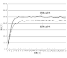
- the figure showing the change of the upper surface temperature of the plate in the case where the maximum output of the gas burner of the heating cooker of FIG. 1 is 950 kcal / h and 850 kcal / h.
- FIG. 1 is a schematic perspective view of a cooking device 10 according to an embodiment of the present invention
- FIG. 2 is an exploded perspective view of the cooking device 10.
- the cooking device 10 shown in these figures is a cooking device that heats food by burning gas as a heat source, and can be called a grilled meat device because it is particularly suitable for grilling meat.
- the present invention may be used not only for meat but also for baking other foods such as vegetables.
- the cooking device 10 shown in the figure is used by storing gas as a heat source in a cartridge-type cassette cylinder 28 and connecting the cassette cylinder 28 to the heating cooking device 10. For this reason, the cooker 10 in the figure is also called a portable cooker, a portable cooker, a cassette cooker, or the like.
- the heating cooker 10 is disposed above the gas burner 20 with a gas burner 20 for burning the fuel gas in the connected cassette cylinder 28, and is used for placing at least meat for baking. Plate 30.
- the gas injected into the cassette cylinder 28 is liquefied petroleum gas such as butane, isobutane, propane, and combinations thereof. In this embodiment, isobutane is about 30% and normal butane is about 70%. Some liquefied butane is used.
- the main body 12 is provided with a gas burner 20 and a cylinder housing chamber 23 in a housing 15, and the gas burner 20 and the cylinder housing chamber 23 have a partition wall in which heat-resistant coating is applied to steel. It is separated by a portion 16.
- the cylinder accommodating chamber 23 is a room for accommodating the cassette cylinder 28, and is exposed to the outside by opening the lid 22 that can be rotated in the R1 direction around the hinge 25, whereby the cassette cylinder 28 can be replaced. It becomes.
- a cylinder connecting portion 27 inside the cylinder accommodating chamber 23, and a cassette cylinder 28 can be attached to and detached from this cylinder connecting portion 27.
- the fuel gas led out from the cassette cylinder 28 enters the governor provided in the cylinder connection portion 27 and the pressure is adjusted.
- the maximum pressure adjusted by the governor (the maximum output of the gas burner 20 and Is about 3.3 ⁇ 10 ⁇ 3 MPa.
- the cylinder connecting portion 27 is connected to the operation knob 24 so that the amount of gas supplied from the cassette cylinder 28 can be adjusted.
- the fuel gas supplied from the cassette cylinder 28 via the cylinder connection portion 27 is supplied to the gas burner 20 through the gas conduit 89.
- the gas burner 20 has a burner body 17 that mixes fuel gas and primary air to generate a mixed gas, and a burner head 18 provided on the burner body 17.
- the burner head 18 has a plurality of flame openings 19 exposed to the outside, and a mixed gas is ejected from the flame openings 19.
- the igniter 38 is pushed by the rotation of the operation knob 24 to generate a pulse voltage, and the spark plug 39 is discharged by the pulse voltage, whereby the mixed gas is ignited and a flame is generated.
- the flame is generated in an annular shape around the outside of the burner head 18 and is an external flame type gas burner having a relatively low flame height.
- the present invention is not limited to this, and may be an internal flame type in which a flame is directed inward.
- the casing 15 that houses the gas burner 20 has a plurality of air intake ports 35 for taking in a plurality of secondary air.
- the position of the air intake 35 in the height direction corresponds to the position of the flame (see FIG. 3).
- the casing 15 has a circular opening 33 above the burner head 18, and a water container 40 is connected to the position of the opening 33.
- FIG. 3 is a partial cross-sectional view taken along the line AA of FIG.
- FIG. 3 shows a state in which water is put in the water container 40.
- 3 is an enlarged view of the periphery of a through-hole 52 and a water storage portion 44 described later, and the view surrounded by a two-dot chain line is an enlarged view of a longitudinal section of the plate 30.
- FIG. The water container 40 is detachably connected to the housing 15 of the main body 12 so as to prevent the heating cooker 10 and the cassette cylinder 28 accommodated therein from being overheated.
- the water container 40 has a larger diameter L4 than the opening 33 of the housing 15, so that the edge thereof contacts the periphery of the opening 33 of the housing 15, so that the housing It has an exposed portion 40 ⁇ / b> A that can be placed on the body 15 and is exposed to the outside, and a water storage portion 44 that is disposed inside the opening 33 of the housing 15.
- the water reservoir 44 is a recess having an opening 46 facing the plate 30 and storing water. The water temperature in the water reservoir 44 is reduced by steam of the water in the water reservoir 44, and cooking is performed. Overheating of the container 10 and the cassette cylinder 28 accommodated therein is prevented.
- the entire water container 40 has a substantially donut shape, and a circular hole 42 is formed in the center.
- the diameter L1 of the circular hole 42 is at least larger than the diameter L2 of the burner head 18, and L1 in the figure is about 1.6 to 1.8 times L2.
- the water storage part 44 is arrange
- the water storage unit 44 is inserted downward from the opening 33 of the housing 15, and the gas supply amount to the gas burner 20 is maximized (the gas burner 20 is at the maximum output).
- the flame FR is arranged so as to surround the flame FR so that the outer flame FR1 of the flame FR and the water WT face each other (so that the position in the height direction is the same). Is effectively evaporated.
- the water storage part 44 has the width
- the exposed portion 40A disposed on the upper side of the casing 15 of the water container 40 has an upward step portion 48 disposed on the outer side of the water storage portion 44, and the plate 30 is placed on the upward step portion 48. Is done. Therefore, the diameter L3 of the plate 30 shown in FIG. 2 is formed smaller than the diameter L4 of the entire water container 40. Further, the end face of the peripheral edge 30A of the plate 30 is opposed to the side wall portion 49 erected from the upward stepped portion 48 of the water container 40 so as to leave a slight gap as shown in FIG.
- the diameter L3 of the plate 30 shown in FIG. 2 is slightly smaller than the diameter L5 of the inner peripheral surface of the side wall 49 of the water container 40 shown in FIG. When it is placed at 48, it is generally fitted, and movement in the horizontal direction during use is restricted.
- the first and second protrusions 36 and 37 are provided on one side of the water container 40 so that it is difficult to place other plates (particularly large plates) that are not dedicated products.
- the first protrusion 36 is connected to the side wall surface 49 and extends upward from the upper end of the water container 40 so that a plate having a diameter larger than the diameter L4 of the water container 40 is not placed thereon.
- the second protrusion 37 is located at a position lower than the first protrusion 36 (a position hidden when the dedicated plate 30 is placed), and the circular hole 42 in the center of the water container 40.
- FIG. 4 is a plan view of the plate 30 of FIG. 1
- FIG. 5 is a perspective view of the plate 30 of FIG. 1 viewed from the lower surface side.
- the plate 30 has a high thermal conductivity material and a low thermal conductivity material having relatively different thermal conductivities
- the longitudinal section has a three-layer structure.
- the central layer 60 having a three-layer structure is formed of at least a high thermal conductivity material having a higher thermal conductivity than iron, for example, aluminum, an aluminum alloy obtained by alloying this with copper, manganese, silicon, zinc, nickel, or copper.
- the upper layer 61 and the lower layer 62 of the three-layer structure are formed by coating the surface of the central layer 60 (high thermal conductivity material) with a low thermal conductivity material having a lower thermal conductivity than the high thermal conductivity material.
- it is made of a thin film fluororesin.
- the thermal conductivity of the fluororesin is 0.23 W / (m ⁇ k).
- such a plate 30 has a circular plate shape as a whole, and is curved so as to be convex upward. It inclines so that it may go down from 30B toward the periphery 30A.
- the plate 30 of the present embodiment is uniformly curved and inclined as a whole, and the radius of curvature r2 is about 561 mm.
- the plate 30 has a heat filling part 30D (which will be described in detail later) which is an area mainly for grilling meat, and a temperature lower than that of the heat filling part 30D. It consists of an outer peripheral portion 30C for heating other ingredients. A plurality of through holes 52 are formed in the outer peripheral portion 30 ⁇ / b> C, and these through holes 52 face the opening 46 of the water storage unit 44. Thereby, the fat extracted from the meat placed on the plate 30 flows toward the peripheral edge 30 ⁇ / b> A and easily falls from the through hole 52 to the water storage portion 44. And the fat which fell to the water storage part 44 is cooled with the water in the water storage part 44, and it can prevent that smoke comes out. In addition, the water vapor
- the plate 30 has a plurality of groove portions 54 on the upper surface of the outer peripheral portion 30 ⁇ / b> C on the side of the central portion 30 ⁇ / b> B (a hot flashing portion 30 ⁇ / b> D described later).
- the groove part 54 is formed so that the fat extracted from the meat can flow smoothly to the outer peripheral part 30C, and is connected to the through hole 52 formed in the outer peripheral part 30C. Thereby, the fat that has fallen into the groove portion 54 can be dropped from the through hole 52 to the water storage portion 44.
- the specific shape of the groove portion 54 will be described later in detail. As shown in FIG.
- the inner bottom surface 54a of the groove portion 54 is also lowered from the central portion 30B toward the peripheral edge 30A, so that the oil can be smoothly passed to the through hole 52.
- the groove 54 is formed at a predetermined angle with respect to the radial direction r1 without being along the radial direction r1 of the plate 30 in plan view. Are angled by curving. Thereby, even if the plate 30 is a dome shape entirely, it can prevent that foodstuffs, such as meat, slide down.
- the through hole 52 of the outer peripheral portion 30C is bent to the opposite side to the groove portion 54 to have a predetermined angle ⁇ 2, and even if a small food material moves to the outer peripheral portion 30C along the groove portion 54. It can prevent falling from the through hole 52.
- a plurality of (four in the case of the figure) leg portions 56 projecting downward are formed on the peripheral edge 30A of the plate 30 at intervals.
- the height H2 of the leg 56 is about 3 mm.
- the exhaust of the combustion heat of this embodiment is only two types, that is, the exhaust route AR1 between the legs 56 of the peripheral edge 30A and the exhaust route AR2 from the through hole 52, and the through hole 52 is closed with food. Considering the fear of escaping, the significance of the exhaust route AR1 is great.
- the heating cooker 10 of the present embodiment has the above characteristics, and further has the following characteristics.
- the lower surface 30F of the plate 30 is convex upward so as to cover the upper side of the flame port 19 of the gas burner 20 and form a space S1 where combustion heat is generated on the lower surface 30F side. It has the heat haze part 30D made into.
- a circular frame-shaped portion 67 protruding toward the gas burner 20 is formed on the lower surface 30 ⁇ / b> F of the plate 30.
- the height H1 of the frame-shaped portion 67 in the figure is 6 mm.
- the space surrounded by is a space (hereinafter referred to as “heat-filled space”) S1 where combustion heat is generated, and the volume of the heat-filled space S1 of this embodiment is about 162, 198 mm 3 .
- the flame FR in the state of maximum output is located inside the heat-filled space S1 in the horizontal direction. Therefore, even if the combustion heat is sufficiently spread in the heat-filled space S1, and the flame does not contact the plate 30, the meat placed on the heat-filled portion 30D corresponding to the heat-filled space S1 is sufficient. Can be heated. And since it is not necessary to make a flame contact the plate 30 directly, the local overheating of the plate 30 can be prevented and the smoke which generate
- the fat can be dropped into the water storage portion 44 immediately below the frame-shaped portion 67.
- the heat-filling space S1 has a small area facing the opening 46 facing the plate 30 side of the water storage section 44, as shown in FIG. Therefore, depending on the thermal power, there is a risk that water vapor generated from the water reservoir 44 may enter the heat-filled space S1.
- the maximum output of the gas burner 20 is adjusted so that the flame FR does not come into contact with the lower surface 30F of the plate 30 as shown in FIG. 3, and in the case of this embodiment, the upper end of the flame FR from the burner head 18 is adjusted.
- the height H3 is about 20 mm (considering that if this height is H3, even if wind blows, it will not disappear directly), the upper end of the flame FR to the lower end of the frame-shaped part 67 (the closest heat-filling space)
- the height H4 to the portion S1 is about 24.2 mm
- the height H5 from the upper end of the flame FR to the center of the lower surface 30F (the portion of the furthest heat-filling space S1) is about 35.5 mm.
- the upper surface temperature of the hot filling portion 30D is between about 210 ° C. and 250 ° C. It is going to change. This upper surface temperature of about 210 to 250 ° C. is considered to be the optimum temperature for grilling meat. This is because if the upper surface temperature of the plate 30 exceeds 250 ° C., the fat content from the meat burns and smoke tends to be emitted, and conversely, if the temperature falls below 210 ° C., a lot of the moisture in the meat is lost without burning the meat. As a result, the meat is deflated and not delicious. Note that the taste of meat is the result of a sensory test (beef is used in this embodiment), and also depends on the type of meat and the presence or absence of seasonings. There may be an error (for example, 200 ° C.).
- the maximum output of the gas burner 20 is set to 850 to 950 kcal / h, and the unevenness of the plate 30 (that is, on the upper surface of the hot flashing portion 30D). It can be realized by devising the surface shape formed by the required grooves 54 formed. However, in the case of this embodiment, it is particularly dangerous to place a large plate, so the plate is unavoidably small, and various configurations affect the upper surface temperature of the heat sink 30D. Therefore, in addition to adjusting the surface area by forming the groove 54 on the upper surface of the heat-filled portion 30D, the through hole 52 formed in the outer peripheral portion 30C outside the heat-filled portion 30D.
- the plate 30 is roughly divided into a circular heat-filled portion 30D located above the heat-filling space S1, and an outer peripheral portion 30C formed integrally with the outer side (outer peripheral side) in a ring shape.
- the heat-filled portion 30 ⁇ / b> D is substantially circular in plan view and has a central portion 30 ⁇ / b> B having no irregularities, and is outside the central portion 30 ⁇ / b> B and has a plurality of groove portions 54. It can be distinguished from the region 30G.
- the central portion 30B, the region 30G in which the groove portion 54 is formed, and the outer peripheral portion 30C are concentric circles.
- the area of the heat sink 30D is about 183.8 cm 2 (about 43% of the total area), and the area of the outer peripheral part 30C is about 244. .2 cm 2 (about 57% of the total area).
- the thickness D1 of the peripheral edge 30A bent downward as shown in FIG. 5 is about 3.0 mm, and the thickness D2 of the other region excluding the groove 54 shown in FIG.
- the depth D3 is about 0.6 mm, and the thickness D4 where the groove 54 is located is 1.4 mm.
- the total area of the upper surface 30E when the groove portion 54 is not formed is about 428 cm 2 , whereas in the present embodiment in which the groove portion 54 is formed (mostly the upper surface of the heat-filled portion 30D).
- the total area of the upper surface 30E is about 437 cm 2 , and the surface area is increased by about 2% (that is, the unevenness of the plate 30 formed of the groove portion 54 increases the surface area to improve heat dissipation. Is).
- the plurality of grooves 54 have the same shape. As shown in FIG. 4 and FIG. 6, which is an enlarged perspective view of the vicinity of B shown in FIG.
- the inner side surface 54a opposite to 30C is an inclined surface that is inclined so as to increase the depth toward the outer peripheral portion 30C.
- the periphery 54b of the opening on the inner side surface in the width direction is inclined so that the width dimension W2 increases toward the top.
- the through hole 52 shown in FIG. 4 has a length L6 of 27 mm and a total opening area of about 45 cm 2 , and has a total area (about 437 cm 2 ) of the present embodiment in which the groove portion 54 is formed on the upper surface 30E of the plate 30. On the other hand, it is about 10%.
- the through holes 52 are used to reduce the surface area of the plate 30, but are more affected by the evaporation of water in the water storage portion 44. For this reason, the temperature of the plate 30 increases as the opening area increases. It works to lower.
- FIG. 7 which is an enlarged perspective view in which the vicinity of C shown in FIG.
- the inner side surface 52a of the through hole 52 is different from the groove portion 54. It is vertical and can quickly drop fat. Further, the width dimension W3 of the groove portion 54 and the width dimension W4 of the through hole 52 in the portion JT where the through hole 52 and the groove portion 54 are connected are substantially the same. Therefore, the fat that has flowed through the groove portion 54 quickly passes through the through hole 52 without staying at the connected portion JT, and smoke can be prevented more effectively.
- the heating cooker Even for a plate 30 that is relatively small and tends to be hot, such as a portable cassette stove (10), the temperature of the upper surface of the hot flashing portion 30D is below the maximum output (850 to 950 kcal / h) of the gas burner 20. Was allowed to transition between approximately 210-250 ° C.
- FIG. 8 is a result of an experiment using the heating cooker 10 of the present embodiment, and shows a change in the upper surface temperature of the plate when the maximum output of the gas burner is 950 kcal / h and when it is 850 kcal / h. It is.
- the temperature at a position 4 cm away from the center of the plate in the radial direction that is, the region 30 ⁇ / b> G in which the groove 54 in FIG. 4 is formed
- the plate is heated without placing ingredients such as meat on the plate, and the state after heating the plate is the state after the heat is taken away by the meat (the meat affects the temperature of the plate). It can be equated with the state after no longer being given.
- the maximum output of the gas burner when the maximum output of the gas burner is set to 950 kcal / h, the temperature reaches nearly 250 ° C. in about 6 minutes (the plate has been heated), and then the upper surface of the plate reaches 250 ° C. for more than 30 minutes. It was around °C. From this, it can be seen that it is difficult to smoke until the meat is baked with the gas burner at the maximum output. Further, when the maximum output of the gas burner was 850 kcal / h, it reached nearly 210 ° C. in about 8 minutes (the plate was heated), and the upper surface of the plate was around 210 ° C. for more than 30 minutes thereafter. . From this, even if the maximum output of the gas burner is 850 kcal / h, it is possible to bake delicious meat that is hard to smoke and does not wither until the meat is baked.
- the plate 30 shown in FIG. 3 includes a frame-shaped portion 67 (see also FIG. 5) that protrudes toward the gas burner 20 in order to form the heat-filling space S1, and is more horizontal than the frame-shaped portion 67.
- the through hole 52 is provided on the outer side in the direction, the frame-shaped portion 67 and the through hole 52 are separated from each other so that meat fat does not accumulate due to surface tension.
- the frame-shaped portion 67 is close to the grease falling from the through-hole 52, a part of the grease comes into contact with the frame-shaped portion 67, and the corner portion between the frame-shaped portion 67 and the through-hole 52 due to surface tension.
- the frame portion 67 and the through-hole 52 are separated from each other so that the contact of fat with the frame portion 67 can be effectively avoided.
- fat adheres to the lower surface 30F of the plate 30, and the situation where it burns and smoke is generated can be effectively prevented.
- the portion 70 between the frame-shaped portion 67 and the through hole 52 is located immediately adjacent to the exhaust route AR2 that passes through the through hole 52, and thus is relatively easily heated. This is effective in preventing smoke generation.
- 3 is preferably about 3 mm or more when the radius of curvature r2 of the plate 30 is about 561 mm as described above. In the case of the form, it is about 3 mm.
- the inventor initially thought that the fat should not go around the heat-filled space S1 and tried to double the frame-shaped portion 67, but still smoke from between the frame-shaped portion and the through hole. I found out. Therefore, as in the present embodiment, the frame-shaped portion 67 and the through-hole 52 are separated by a required dimension, so that the structure does not collect fat in the first place, and thereby the generation of smoke can be effectively reduced. .
- the present embodiment is configured as described above.
- the maximum output of the gas burner 20 850 to 950 kcal / h
- the configuration of the plate 30 mainly through the groove portion 54.
- the upper surface temperature of the upper surface of the outer peripheral portion 30 ⁇ / b> C becomes lower than that of at least the hot-flooded portion 30 ⁇ / b> D as the ambient temperature decreases due to the water vapor from the water storage unit 44, smoke is not rarely generated.
- the lower surface of the plate 30 does not allow the fat to wrap around by the frame-shaped portion 67, and smoke is not usually generated therefrom.
- the portion 70 that exists immediately above the exhaust route AR2 between the frame-shaped portion 67 and the through hole 52 that may cause smoke on the lower surface of the plate 30. was able to suppress the generation of smoke by preventing the accumulation of fat.
- the plate 30 of the present embodiment has an outer peripheral portion 30C on the further outer side of the hot-warming portion 30D, but the outer peripheral portion 30C is not necessarily required in the present invention, and only the hot-warming portion 30D. It may be a plate made of In that case, the gas burner 20 is formed by increasing the surface area by increasing the unevenness of the heat-filled portion 30D in consideration of the temperature effect on the heat-filled portion 30D by the outer peripheral portion 30C having a relatively low temperature.
- the upper surface temperature of the hot flashing section 30D is changed between about 210 to 250 ° C. under the maximum output (850 to 950 kcal / h). Further, even when the outer peripheral portion 30C exists on the plate 30 as in the present embodiment, the through hole 52 is not formed in the outer peripheral portion 30C, and the surface area of the outer peripheral portion 30C is increased by the uneven shape, or the peripheral edge 30A.
- the upper surface temperature of the outer peripheral portion 30C is made lower than that of the hot flashing portion 30D by increasing the leg portion 56 of the outer peripheral portion 30D. May be allowed to transition between approximately 210-250 ° C.
- the maximum output of the gas burner 20 is set to 850 to 950 kcal / h so that the flame does not come into contact with the lower surface of the plate 30, and the plate 30 is mounted with the upper surface temperature of the hot flashing portion 30D.
- the most characteristic feature is that the unevenness is formed so as to change between about 210 ° C. and 250 ° C. under the maximum output in the state after heat removal by the meat.
- SYMBOLS 10 Cooking device (cassette cooker), 12 ... Main part, 19 ... Flame port, 20 ... Gas burner, 30 ... Plate, 30C ... Outer peripheral part, 30D ... Heat storage part, 44 ... Water storage part, 52 ... Through hole, 54 ... Groove part (unevenness), 67 ... Frame-like part, S1 ... Space where heat of combustion is stored (heat-filled space) , FR ... Flame
Landscapes
- Engineering & Computer Science (AREA)
- Food Science & Technology (AREA)
- Chemical & Material Sciences (AREA)
- Combustion & Propulsion (AREA)
- Mechanical Engineering (AREA)
- General Engineering & Computer Science (AREA)
- Baking, Grill, Roasting (AREA)
Priority Applications (2)
| Application Number | Priority Date | Filing Date | Title |
|---|---|---|---|
| CN201790000851.3U CN209610879U (zh) | 2016-05-12 | 2017-05-09 | 加热烹调器 |
| KR1020187036124A KR102363015B1 (ko) | 2016-05-12 | 2017-05-09 | 가열 조리기 |
Applications Claiming Priority (2)
| Application Number | Priority Date | Filing Date | Title |
|---|---|---|---|
| JP2016-096268 | 2016-05-12 | ||
| JP2016096268A JP6375336B2 (ja) | 2016-05-12 | 2016-05-12 | 加熱調理器 |
Publications (1)
| Publication Number | Publication Date |
|---|---|
| WO2017195777A1 true WO2017195777A1 (ja) | 2017-11-16 |
Family
ID=60267079
Family Applications (1)
| Application Number | Title | Priority Date | Filing Date |
|---|---|---|---|
| PCT/JP2017/017542 Ceased WO2017195777A1 (ja) | 2016-05-12 | 2017-05-09 | 加熱調理器 |
Country Status (5)
| Country | Link |
|---|---|
| JP (1) | JP6375336B2 (https=) |
| KR (1) | KR102363015B1 (https=) |
| CN (1) | CN209610879U (https=) |
| TW (1) | TWI758292B (https=) |
| WO (1) | WO2017195777A1 (https=) |
Cited By (12)
| Publication number | Priority date | Publication date | Assignee | Title |
|---|---|---|---|---|
| US10390656B2 (en) | 2017-08-09 | 2019-08-27 | Sharkninja Operating Llc | Cooking device and components thereof |
| USD873602S1 (en) | 2018-08-09 | 2020-01-28 | Sharkninja Operating Llc | Lid part of a food preparation device |
| USD874211S1 (en) | 2018-08-09 | 2020-02-04 | Sharkninja Operating Llc | Food preparation device and parts thereof |
| USD903413S1 (en) | 2018-08-09 | 2020-12-01 | Sharkninja Operating Llc | Cooking basket |
| USD914436S1 (en) | 2018-06-19 | 2021-03-30 | Sharkninja Operating Llc | Air diffuser with food preparation pot |
| USD918654S1 (en) | 2019-06-06 | 2021-05-11 | Sharkninja Operating Llc | Grill plate |
| US11033146B2 (en) | 2019-02-25 | 2021-06-15 | Sharkninja Operating Llc | Cooking device and components thereof |
| USD922126S1 (en) | 2019-06-06 | 2021-06-15 | Sharkninja Operating Llc | User interface for a food preparation device |
| US11134808B2 (en) | 2020-03-30 | 2021-10-05 | Sharkninja Operating Llc | Cooking device and components thereof |
| USD932833S1 (en) | 2018-08-09 | 2021-10-12 | Sharkninja Operating Llc | Reversible cooking rack |
| US11751710B2 (en) | 2019-02-25 | 2023-09-12 | Sharkninja Operating Llc | Guard for cooking system |
| US12616334B2 (en) | 2020-12-31 | 2026-05-05 | Sharkninja Operating Llc | Cooking device and components thereof |
Families Citing this family (1)
| Publication number | Priority date | Publication date | Assignee | Title |
|---|---|---|---|---|
| JP7166632B2 (ja) | 2019-12-25 | 2022-11-08 | サンタ株式会社 | ロースター |
Citations (7)
| Publication number | Priority date | Publication date | Assignee | Title |
|---|---|---|---|---|
| JPH0271432U (https=) * | 1988-11-15 | 1990-05-31 | ||
| JPH10179411A (ja) * | 1996-11-28 | 1998-07-07 | Kokei Ri | 焼肉盤 |
| JP3065226U (ja) * | 1999-06-25 | 2000-02-02 | 弼彙 趙 | 調理装置 |
| JP2000150129A (ja) * | 1998-11-06 | 2000-05-30 | Toshiba Corp | 電磁誘導加熱方式ホットプレート |
| JP2001275844A (ja) * | 2000-03-31 | 2001-10-09 | Totsu:Kk | 焼物調理器 |
| JP2003290049A (ja) * | 2002-04-01 | 2003-10-14 | Santa Kk | 鉄板焼テーブル |
| JP2016054916A (ja) * | 2014-09-09 | 2016-04-21 | 東京瓦斯株式会社 | 加熱調理器 |
Family Cites Families (7)
| Publication number | Priority date | Publication date | Assignee | Title |
|---|---|---|---|---|
| JPS601010A (ja) | 1983-06-15 | 1985-01-07 | Mitsubishi Heavy Ind Ltd | 車両空調装置 |
| JPH0365226U (https=) * | 1989-10-27 | 1991-06-25 | ||
| TWI255325B (en) * | 2003-10-30 | 2006-05-21 | Huei-Shiung Jau | Device for efficiently utilizing heat source |
| US20060162574A1 (en) | 2005-01-21 | 2006-07-27 | Prip Peter F | Modified grill top cooking tool with radiused end caps |
| TW200928237A (en) * | 2007-12-24 | 2009-07-01 | Pro Iroda Ind Inc | A heating device for fuel gas bottle |
| JP3142998U (ja) | 2008-04-22 | 2008-07-03 | 進 須藤 | 食品用無煙焼き物プレート |
| KR20130005392U (ko) * | 2012-03-06 | 2013-09-16 | 김장현 | 고기 구이판 |
-
2016
- 2016-05-12 JP JP2016096268A patent/JP6375336B2/ja active Active
-
2017
- 2017-05-09 CN CN201790000851.3U patent/CN209610879U/zh active Active
- 2017-05-09 WO PCT/JP2017/017542 patent/WO2017195777A1/ja not_active Ceased
- 2017-05-09 KR KR1020187036124A patent/KR102363015B1/ko active Active
- 2017-05-11 TW TW106115627A patent/TWI758292B/zh active
Patent Citations (7)
| Publication number | Priority date | Publication date | Assignee | Title |
|---|---|---|---|---|
| JPH0271432U (https=) * | 1988-11-15 | 1990-05-31 | ||
| JPH10179411A (ja) * | 1996-11-28 | 1998-07-07 | Kokei Ri | 焼肉盤 |
| JP2000150129A (ja) * | 1998-11-06 | 2000-05-30 | Toshiba Corp | 電磁誘導加熱方式ホットプレート |
| JP3065226U (ja) * | 1999-06-25 | 2000-02-02 | 弼彙 趙 | 調理装置 |
| JP2001275844A (ja) * | 2000-03-31 | 2001-10-09 | Totsu:Kk | 焼物調理器 |
| JP2003290049A (ja) * | 2002-04-01 | 2003-10-14 | Santa Kk | 鉄板焼テーブル |
| JP2016054916A (ja) * | 2014-09-09 | 2016-04-21 | 東京瓦斯株式会社 | 加熱調理器 |
Cited By (70)
| Publication number | Priority date | Publication date | Assignee | Title |
|---|---|---|---|---|
| US11445856B2 (en) | 2017-08-09 | 2022-09-20 | Sharkninja Operating Llc | Cooking device and components thereof |
| US10660472B2 (en) | 2017-08-09 | 2020-05-26 | Sharkninja Operating Llc | Cooking device and components thereof |
| US10405698B2 (en) | 2017-08-09 | 2019-09-10 | Sharkninja Operating Llc | Cooking device and components thereof |
| US10413121B2 (en) | 2017-08-09 | 2019-09-17 | Sharkninja Operating Llc | Cooking device and components thereof |
| US10413122B2 (en) | 2017-08-09 | 2019-09-17 | Sharkninja Operating Llc | Cooking device and components thereof |
| US10485378B2 (en) | 2017-08-09 | 2019-11-26 | Sharkninja Operating Llc | Cooking device and components thereof |
| US11889950B2 (en) | 2017-08-09 | 2024-02-06 | Sharkninja Operating Llc | Cooking device and components thereof |
| US11759049B2 (en) | 2017-08-09 | 2023-09-19 | Sharkninja Operating Llc | Cooking device and components thereof |
| US11759048B2 (en) | 2017-08-09 | 2023-09-19 | Sharkninja Operating Llc | Cooking device and components thereof |
| US11627834B2 (en) | 2017-08-09 | 2023-04-18 | Sharkninja Operating Llc | Cooking system for cooking food |
| US11547242B2 (en) | 2017-08-09 | 2023-01-10 | Sharkninja Operating Llc | Cooking device and components thereof |
| US11547243B2 (en) | 2017-08-09 | 2023-01-10 | Sharkninja Operating Llc | Cooking device and components thereof |
| US10390656B2 (en) | 2017-08-09 | 2019-08-27 | Sharkninja Operating Llc | Cooking device and components thereof |
| US10646070B2 (en) | 2017-08-09 | 2020-05-12 | Sharkninja Operating Llc | Cooking device and components thereof |
| US10653270B2 (en) | 2017-08-09 | 2020-05-19 | Sharkninja Operating Llc | Cooking device and components thereof |
| US11109710B2 (en) | 2017-08-09 | 2021-09-07 | Sharkninja Operating Llc | Cooking device and components thereof |
| US10674868B2 (en) | 2017-08-09 | 2020-06-09 | Sharkninja Operating Llc | Cooking device and components thereof |
| US10682011B2 (en) | 2017-08-09 | 2020-06-16 | Sharkninja Operating Llc | Cooking device and components thereof |
| US10405697B2 (en) | 2017-08-09 | 2019-09-10 | Sharkninja Operating Llc | Cooking device and components thereof |
| US11399657B2 (en) | 2017-08-09 | 2022-08-02 | Sharkninja Operating Llc | Cooking device and components thereof |
| US11363910B2 (en) | 2017-08-09 | 2022-06-21 | Sharkninja Operating Llc | Cooking device and components thereof |
| US11089902B2 (en) | 2017-08-09 | 2021-08-17 | Sharkninja Operating Llc | Cooking device and components thereof |
| US11089903B2 (en) | 2017-08-09 | 2021-08-17 | Sharkninja Operating Llc | Cooking device and components thereof |
| US11304561B2 (en) | 2017-08-09 | 2022-04-19 | Sharkninja Operating Llc | Cooking device and components thereof |
| US11266267B2 (en) | 2017-08-09 | 2022-03-08 | Sharkninja Operating Llc | Cooking device and components thereof |
| US11278151B2 (en) | 2017-08-09 | 2022-03-22 | Sharkninja Operating Llc | Cooking device and components thereof |
| US11266268B2 (en) | 2017-08-09 | 2022-03-08 | Sharkninja Operating Llc | Cooking device and components thereof |
| USD948938S1 (en) | 2018-06-19 | 2022-04-19 | Sharkninja Operating Llc | Air diffuser |
| USD914447S1 (en) | 2018-06-19 | 2021-03-30 | Sharkninja Operating Llc | Air diffuser |
| USD914436S1 (en) | 2018-06-19 | 2021-03-30 | Sharkninja Operating Llc | Air diffuser with food preparation pot |
| USD903413S1 (en) | 2018-08-09 | 2020-12-01 | Sharkninja Operating Llc | Cooking basket |
| USD903415S1 (en) | 2018-08-09 | 2020-12-01 | Sharkninja Operating Llc | Cooking basket |
| USD929793S1 (en) | 2018-08-09 | 2021-09-07 | Sharkninja Operating Llc | Food preparation device |
| USD929173S1 (en) | 2018-08-09 | 2021-08-31 | Sharkninja Operating Llc | Food preparation device |
| USD873602S1 (en) | 2018-08-09 | 2020-01-28 | Sharkninja Operating Llc | Lid part of a food preparation device |
| USD935259S1 (en) | 2018-08-09 | 2021-11-09 | Sharkninja Operating Llc | Food preparation device |
| USD883015S1 (en) | 2018-08-09 | 2020-05-05 | Sharkninja Operating Llc | Food preparation device and parts thereof |
| USD931680S1 (en) | 2018-08-09 | 2021-09-28 | Sharkninja Operating Llc | Cooking basket |
| USD934027S1 (en) | 2018-08-09 | 2021-10-26 | Sharkninja Operating Llc | Reversible cooking rack |
| USD874211S1 (en) | 2018-08-09 | 2020-02-04 | Sharkninja Operating Llc | Food preparation device and parts thereof |
| USD876874S1 (en) | 2018-08-09 | 2020-03-03 | Sharkninja Operating Llc | User interface for a food preparation device |
| USD940503S1 (en) | 2018-08-09 | 2022-01-11 | Sharkninja Operating Llc | Cooking basket |
| USD941090S1 (en) | 2018-08-09 | 2022-01-18 | Sharkninja Operating Llc | Cooking basket |
| USD929794S1 (en) | 2018-08-09 | 2021-09-07 | Sharkninja Operating Llc | Food preparation device |
| USD932833S1 (en) | 2018-08-09 | 2021-10-12 | Sharkninja Operating Llc | Reversible cooking rack |
| USD883014S1 (en) | 2018-08-09 | 2020-05-05 | Sharkninja Operating Llc | Food preparation device |
| USD920732S1 (en) | 2018-08-09 | 2021-06-01 | Sharkninja Operating Llc | Food preparation device |
| USD883017S1 (en) | 2018-08-09 | 2020-05-05 | Sharkninja Operating Llc | User interface for food preparation device |
| USD883016S1 (en) | 2018-08-09 | 2020-05-05 | Sharkninja Operating Llc | Food preparation device and parts thereof |
| USD903414S1 (en) | 2018-08-09 | 2020-12-01 | Sharkninja Operating Llc | Cooking basket |
| US11751722B2 (en) | 2019-02-25 | 2023-09-12 | Sharkninja Operating Llc | Cooking device and components thereof |
| US11147415B2 (en) | 2019-02-25 | 2021-10-19 | Sharkninja Operating Llc | Cooking device and components thereof |
| US12226039B2 (en) | 2019-02-25 | 2025-02-18 | Sharkninja Operating Llc | Guard for cooking system |
| US11033146B2 (en) | 2019-02-25 | 2021-06-15 | Sharkninja Operating Llc | Cooking device and components thereof |
| US11363911B2 (en) | 2019-02-25 | 2022-06-21 | Sharkninja Operating Llc | Cooking device and components thereof |
| US11766152B2 (en) | 2019-02-25 | 2023-09-26 | Sharkninja Operating Llc | Cooking device and components thereof |
| US11751710B2 (en) | 2019-02-25 | 2023-09-12 | Sharkninja Operating Llc | Guard for cooking system |
| US11051654B2 (en) | 2019-02-25 | 2021-07-06 | Sharkninja Operating Llc | Cooking device and components thereof |
| USD934631S1 (en) | 2019-06-06 | 2021-11-02 | Sharkninja Operating Llc | Grill plate |
| USD922126S1 (en) | 2019-06-06 | 2021-06-15 | Sharkninja Operating Llc | User interface for a food preparation device |
| USD982375S1 (en) | 2019-06-06 | 2023-04-04 | Sharkninja Operating Llc | Food preparation device |
| USD1015798S1 (en) | 2019-06-06 | 2024-02-27 | Sharkninja Operating Llc | Food preparation device |
| USD1049746S1 (en) | 2019-06-06 | 2024-11-05 | Sharkninja Operating Llc | Food preparation device |
| USD1054771S1 (en) | 2019-06-06 | 2024-12-24 | Sharkninja Operating Llc | Food preparation device |
| USD918654S1 (en) | 2019-06-06 | 2021-05-11 | Sharkninja Operating Llc | Grill plate |
| US11678765B2 (en) | 2020-03-30 | 2023-06-20 | Sharkninja Operating Llc | Cooking device and components thereof |
| US11647861B2 (en) | 2020-03-30 | 2023-05-16 | Sharkninja Operating Llc | Cooking device and components thereof |
| US11134808B2 (en) | 2020-03-30 | 2021-10-05 | Sharkninja Operating Llc | Cooking device and components thereof |
| US11969118B2 (en) | 2020-03-30 | 2024-04-30 | Sharkninja Operating Llc | Cooking device and components thereof |
| US12616334B2 (en) | 2020-12-31 | 2026-05-05 | Sharkninja Operating Llc | Cooking device and components thereof |
Also Published As
| Publication number | Publication date |
|---|---|
| KR102363015B1 (ko) | 2022-02-16 |
| JP6375336B2 (ja) | 2018-08-15 |
| CN209610879U (zh) | 2019-11-12 |
| JP2017202159A (ja) | 2017-11-16 |
| KR20190008319A (ko) | 2019-01-23 |
| TWI758292B (zh) | 2022-03-21 |
| TW201809551A (zh) | 2018-03-16 |
Similar Documents
| Publication | Publication Date | Title |
|---|---|---|
| JP6375336B2 (ja) | 加熱調理器 | |
| CN104853658B (zh) | 烧烤装置 | |
| JP3173614U (ja) | 断熱機能を有する側板を備えたコンロ | |
| JP2016000075A (ja) | 調理器用のグリル装置 | |
| JP2011143232A (ja) | オリジナル直火式オーブン用本体 | |
| KR20110011146U (ko) | 직화 구이기 | |
| CN210688219U (zh) | 燃烧器和燃气灶具 | |
| TW201701810A (zh) | 可攜式焙燒裝置及使用該焙燒裝置的焙燒方法 | |
| KR20220147305A (ko) | 조리기구 | |
| KR200443515Y1 (ko) | 양면조리를 할 수 있는 가스기기의 그릴용 생선 구이판 | |
| WO2009094879A1 (fr) | Plateau de cuisson pour four à micro-ondes présentant une base à rayonnement de chaleur | |
| KR102390179B1 (ko) | 캠핑용 다기능 구이기 | |
| CN210688224U (zh) | 燃烧器和燃气灶具 | |
| KR102347762B1 (ko) | 직화구이 및 간접구이 겸용 구이용 불판 | |
| KR200359216Y1 (ko) | 조리구이판 | |
| JP2005312672A (ja) | 炭火焼コンロ | |
| JP6967771B2 (ja) | 加熱調理器 | |
| JP6411797B2 (ja) | 加熱調理器 | |
| KR100807064B1 (ko) | 오븐식 휴대용 가스레인지 | |
| KR200315628Y1 (ko) | 과열 방지용 육류구이판 | |
| KR200378565Y1 (ko) | 물의 대류현상과 수압차이를 이용한 물순환식 냉각석쇠 | |
| JP7038396B2 (ja) | 容器及び加熱調理器 | |
| KR200425836Y1 (ko) | 구이판 | |
| KR100717079B1 (ko) | 가스버너가 내장된 테이블 및 이에 사용되는 구이판 | |
| KR200378543Y1 (ko) | 구이용 그릴 |
Legal Events
| Date | Code | Title | Description |
|---|---|---|---|
| NENP | Non-entry into the national phase |
Ref country code: DE |
|
| 121 | Ep: the epo has been informed by wipo that ep was designated in this application |
Ref document number: 17796138 Country of ref document: EP Kind code of ref document: A1 |
|
| ENP | Entry into the national phase |
Ref document number: 20187036124 Country of ref document: KR Kind code of ref document: A |
|
| 122 | Ep: pct application non-entry in european phase |
Ref document number: 17796138 Country of ref document: EP Kind code of ref document: A1 |