WO2017187876A1 - 高圧ポンプ - Google Patents
高圧ポンプ Download PDFInfo
- Publication number
- WO2017187876A1 WO2017187876A1 PCT/JP2017/013165 JP2017013165W WO2017187876A1 WO 2017187876 A1 WO2017187876 A1 WO 2017187876A1 JP 2017013165 W JP2017013165 W JP 2017013165W WO 2017187876 A1 WO2017187876 A1 WO 2017187876A1
- Authority
- WO
- WIPO (PCT)
- Prior art keywords
- fuel
- pressure pump
- plunger
- chamber
- axis
- Prior art date
Links
Images


Classifications
-
- F—MECHANICAL ENGINEERING; LIGHTING; HEATING; WEAPONS; BLASTING
- F02—COMBUSTION ENGINES; HOT-GAS OR COMBUSTION-PRODUCT ENGINE PLANTS
- F02M—SUPPLYING COMBUSTION ENGINES IN GENERAL WITH COMBUSTIBLE MIXTURES OR CONSTITUENTS THEREOF
- F02M55/00—Fuel-injection apparatus characterised by their fuel conduits or their venting means; Arrangements of conduits between fuel tank and pump F02M37/00
- F02M55/04—Means for damping vibrations or pressure fluctuations in injection pump inlets or outlets
-
- F—MECHANICAL ENGINEERING; LIGHTING; HEATING; WEAPONS; BLASTING
- F02—COMBUSTION ENGINES; HOT-GAS OR COMBUSTION-PRODUCT ENGINE PLANTS
- F02M—SUPPLYING COMBUSTION ENGINES IN GENERAL WITH COMBUSTIBLE MIXTURES OR CONSTITUENTS THEREOF
- F02M55/00—Fuel-injection apparatus characterised by their fuel conduits or their venting means; Arrangements of conduits between fuel tank and pump F02M37/00
-
- F—MECHANICAL ENGINEERING; LIGHTING; HEATING; WEAPONS; BLASTING
- F02—COMBUSTION ENGINES; HOT-GAS OR COMBUSTION-PRODUCT ENGINE PLANTS
- F02M—SUPPLYING COMBUSTION ENGINES IN GENERAL WITH COMBUSTIBLE MIXTURES OR CONSTITUENTS THEREOF
- F02M59/00—Pumps specially adapted for fuel-injection and not provided for in groups F02M39/00 -F02M57/00, e.g. rotary cylinder-block type of pumps
- F02M59/02—Pumps specially adapted for fuel-injection and not provided for in groups F02M39/00 -F02M57/00, e.g. rotary cylinder-block type of pumps of reciprocating-piston or reciprocating-cylinder type
- F02M59/10—Pumps specially adapted for fuel-injection and not provided for in groups F02M39/00 -F02M57/00, e.g. rotary cylinder-block type of pumps of reciprocating-piston or reciprocating-cylinder type characterised by the piston-drive
- F02M59/102—Mechanical drive, e.g. tappets or cams
-
- F—MECHANICAL ENGINEERING; LIGHTING; HEATING; WEAPONS; BLASTING
- F02—COMBUSTION ENGINES; HOT-GAS OR COMBUSTION-PRODUCT ENGINE PLANTS
- F02M—SUPPLYING COMBUSTION ENGINES IN GENERAL WITH COMBUSTIBLE MIXTURES OR CONSTITUENTS THEREOF
- F02M59/00—Pumps specially adapted for fuel-injection and not provided for in groups F02M39/00 -F02M57/00, e.g. rotary cylinder-block type of pumps
- F02M59/20—Varying fuel delivery in quantity or timing
- F02M59/36—Varying fuel delivery in quantity or timing by variably-timed valves controlling fuel passages to pumping elements or overflow passages
-
- F—MECHANICAL ENGINEERING; LIGHTING; HEATING; WEAPONS; BLASTING
- F02—COMBUSTION ENGINES; HOT-GAS OR COMBUSTION-PRODUCT ENGINE PLANTS
- F02M—SUPPLYING COMBUSTION ENGINES IN GENERAL WITH COMBUSTIBLE MIXTURES OR CONSTITUENTS THEREOF
- F02M59/00—Pumps specially adapted for fuel-injection and not provided for in groups F02M39/00 -F02M57/00, e.g. rotary cylinder-block type of pumps
- F02M59/44—Details, components parts, or accessories not provided for in, or of interest apart from, the apparatus of groups F02M59/02 - F02M59/42; Pumps having transducers, e.g. to measure displacement of pump rack or piston
- F02M59/46—Valves
-
- F—MECHANICAL ENGINEERING; LIGHTING; HEATING; WEAPONS; BLASTING
- F02—COMBUSTION ENGINES; HOT-GAS OR COMBUSTION-PRODUCT ENGINE PLANTS
- F02M—SUPPLYING COMBUSTION ENGINES IN GENERAL WITH COMBUSTIBLE MIXTURES OR CONSTITUENTS THEREOF
- F02M59/00—Pumps specially adapted for fuel-injection and not provided for in groups F02M39/00 -F02M57/00, e.g. rotary cylinder-block type of pumps
- F02M59/44—Details, components parts, or accessories not provided for in, or of interest apart from, the apparatus of groups F02M59/02 - F02M59/42; Pumps having transducers, e.g. to measure displacement of pump rack or piston
- F02M59/48—Assembling; Disassembling; Replacing
-
- F—MECHANICAL ENGINEERING; LIGHTING; HEATING; WEAPONS; BLASTING
- F04—POSITIVE - DISPLACEMENT MACHINES FOR LIQUIDS; PUMPS FOR LIQUIDS OR ELASTIC FLUIDS
- F04B—POSITIVE-DISPLACEMENT MACHINES FOR LIQUIDS; PUMPS
- F04B1/00—Multi-cylinder machines or pumps characterised by number or arrangement of cylinders
- F04B1/04—Multi-cylinder machines or pumps characterised by number or arrangement of cylinders having cylinders in star- or fan-arrangement
- F04B1/0404—Details or component parts
-
- F—MECHANICAL ENGINEERING; LIGHTING; HEATING; WEAPONS; BLASTING
- F04—POSITIVE - DISPLACEMENT MACHINES FOR LIQUIDS; PUMPS FOR LIQUIDS OR ELASTIC FLUIDS
- F04B—POSITIVE-DISPLACEMENT MACHINES FOR LIQUIDS; PUMPS
- F04B11/00—Equalisation of pulses, e.g. by use of air vessels; Counteracting cavitation
- F04B11/0008—Equalisation of pulses, e.g. by use of air vessels; Counteracting cavitation using accumulators
- F04B11/0016—Equalisation of pulses, e.g. by use of air vessels; Counteracting cavitation using accumulators with a fluid spring
-
- F—MECHANICAL ENGINEERING; LIGHTING; HEATING; WEAPONS; BLASTING
- F04—POSITIVE - DISPLACEMENT MACHINES FOR LIQUIDS; PUMPS FOR LIQUIDS OR ELASTIC FLUIDS
- F04B—POSITIVE-DISPLACEMENT MACHINES FOR LIQUIDS; PUMPS
- F04B11/00—Equalisation of pulses, e.g. by use of air vessels; Counteracting cavitation
- F04B11/0091—Equalisation of pulses, e.g. by use of air vessels; Counteracting cavitation using a special shape of fluid pass, e.g. throttles, ducts
-
- F—MECHANICAL ENGINEERING; LIGHTING; HEATING; WEAPONS; BLASTING
- F04—POSITIVE - DISPLACEMENT MACHINES FOR LIQUIDS; PUMPS FOR LIQUIDS OR ELASTIC FLUIDS
- F04B—POSITIVE-DISPLACEMENT MACHINES FOR LIQUIDS; PUMPS
- F04B53/00—Component parts, details or accessories not provided for in, or of interest apart from, groups F04B1/00 - F04B23/00 or F04B39/00 - F04B47/00
- F04B53/16—Casings; Cylinders; Cylinder liners or heads; Fluid connections
-
- F—MECHANICAL ENGINEERING; LIGHTING; HEATING; WEAPONS; BLASTING
- F02—COMBUSTION ENGINES; HOT-GAS OR COMBUSTION-PRODUCT ENGINE PLANTS
- F02M—SUPPLYING COMBUSTION ENGINES IN GENERAL WITH COMBUSTIBLE MIXTURES OR CONSTITUENTS THEREOF
- F02M2200/00—Details of fuel-injection apparatus, not otherwise provided for
- F02M2200/30—Fuel-injection apparatus having mechanical parts, the movement of which is damped
-
- F—MECHANICAL ENGINEERING; LIGHTING; HEATING; WEAPONS; BLASTING
- F02—COMBUSTION ENGINES; HOT-GAS OR COMBUSTION-PRODUCT ENGINE PLANTS
- F02M—SUPPLYING COMBUSTION ENGINES IN GENERAL WITH COMBUSTIBLE MIXTURES OR CONSTITUENTS THEREOF
- F02M2200/00—Details of fuel-injection apparatus, not otherwise provided for
- F02M2200/31—Fuel-injection apparatus having hydraulic pressure fluctuations damping elements
- F02M2200/315—Fuel-injection apparatus having hydraulic pressure fluctuations damping elements for damping fuel pressure fluctuations
-
- F—MECHANICAL ENGINEERING; LIGHTING; HEATING; WEAPONS; BLASTING
- F02—COMBUSTION ENGINES; HOT-GAS OR COMBUSTION-PRODUCT ENGINE PLANTS
- F02M—SUPPLYING COMBUSTION ENGINES IN GENERAL WITH COMBUSTIBLE MIXTURES OR CONSTITUENTS THEREOF
- F02M55/00—Fuel-injection apparatus characterised by their fuel conduits or their venting means; Arrangements of conduits between fuel tank and pump F02M37/00
- F02M55/008—Arrangement of fuel passages inside of injectors
Definitions
- This disclosure relates to a high-pressure pump that pressurizes and discharges fuel.
- the high-pressure pump of Patent Document 1 is formed to extend from the outer wall of the housing to the radially outer side of the plunger, and includes a fixed portion that is fixed to the internal combustion engine.
- the fixed portion has an insertion hole portion whose axis is parallel to the axis of the plunger.
- the to-be-fixed part is being fixed to the internal combustion engine by inserting a fixing member in the insertion hole, and screwing and fixing to an internal combustion engine.
- the high pressure pump of Patent Document 1 is provided with a pulsation damper in a fuel chamber communicating with a pressurizing chamber to reduce fuel pulsation in the fuel chamber.
- the fuel chamber and the pulsation damper are located on the axis of the plunger.
- the pulsation damper is formed in a hollow disc shape, and is provided so that the axis is parallel to the axis of the plunger.
- two insertion hole portions of the fixed portion are formed so as to be line symmetric with respect to the axis of the plunger as an axis of symmetry.
- the tool used when screwing the fixing member into the internal combustion engine is the fuel. It may interfere with the chamber forming portion and may make it difficult to attach the high pressure pump to the internal combustion engine.
- the outer diameter of the fuel chamber forming portion is reduced so that the tool does not interfere with the fuel chamber forming portion, the outer diameter of the pulsation damper must be reduced, and a sufficient pulsation reducing effect may not be achieved. There is.
- the outer diameter of the pulsation damper is increased in order to achieve a sufficient pulsation reducing effect, the outer diameter of the fuel chamber forming portion is also increased, and the distance between the two insertion holes must be increased. Thereby, there exists a possibility that a high pressure pump may enlarge.
- the present disclosure has been made in view of the above-described problems, and an object of the present disclosure is to provide a small high-pressure pump that has a high effect of reducing fuel pulsation in a fuel chamber and that can be easily attached to an internal combustion engine.
- the present disclosure is a high-pressure pump that is attached to an internal combustion engine, pressurizes and discharges fuel, and supplies the fuel to the internal combustion engine, and includes a housing, a plunger, a fuel chamber forming portion, a pulsation damper, a discharge portion, and a fixed portion. Yes.
- the housing has a pressurizing chamber.
- the plunger moves to increase or decrease the volume of the pressurizing chamber and can pressurize the fuel in the pressurizing chamber.
- the fuel chamber forming part is provided on the radially outer side of the plunger and forms a fuel chamber communicating with the pressurizing chamber.
- the pulsation damper is provided in the fuel chamber and can reduce the pressure pulsation of the fuel in the fuel chamber.
- the discharge part discharges the fuel pressurized in the pressurizing chamber.
- the fixed portion is provided on the radially outer side of the plunger, has an insertion hole portion, and is fixed to the internal combustion engine by a fixing member provided corresponding to the insertion hole portion.
- the fuel chamber formation part is provided in the position which avoided the axis of the penetration hole part. Therefore, it is possible to prevent the tool used when the fixed portion of the high-pressure pump is fixed to the internal combustion engine by the fixing member from interfering with the fuel chamber forming portion. This facilitates the attachment of the high-pressure pump to the internal combustion engine.
- the fuel chamber forming portion is provided on the radially outer side of the plunger, even if the fuel chamber forming portion is enlarged, it is difficult to interfere with the shaft of the insertion hole portion. Therefore, in the present disclosure, it is possible to increase the size of the fuel chamber forming portion while avoiding the shaft of the insertion hole portion. Therefore, the size of the pulsation damper can be increased while suppressing interference between the tool and the fuel chamber forming portion when the fixed portion is fixed by the fixing member, and the effect of reducing fuel pulsation in the fuel chamber can be enhanced.
- the fuel chamber forming portion is provided at a position avoiding the axis of the insertion hole portion on the radially outer side of the plunger, the insertion hole portion is formed at a position relatively close to the axis of the plunger. be able to. Therefore, the physique of the high pressure pump including the fixed portion in which the insertion hole is formed can be reduced.
- the fuel chamber forming portion is provided at a position avoiding the virtual cylindrical surface including the entire inner wall of the insertion hole portion, a tool used for fixing the fixed portion of the high pressure pump to the internal combustion engine by the fixing member is used. Interfering with the fuel chamber forming portion can be more effectively suppressed.
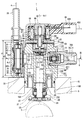
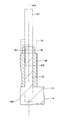
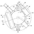
- FIG. 1 is a cross-sectional view illustrating a high-pressure pump according to a first embodiment of the present disclosure.
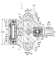
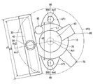
- FIG. 3 is a sectional view taken along line III-III in FIG. 2. Sectional drawing which shows the penetration hole part of the high pressure pump by 1st Embodiment of this indication, and its vicinity.
- the schematic diagram which shows the high pressure pump by 1st Embodiment of this indication. Sectional drawing which shows the penetration hole part of the high pressure pump by 2nd Embodiment of this indication, and its vicinity.
- the schematic diagram which shows the high pressure pump by 4th Embodiment of this indication The schematic diagram which shows the high pressure pump by 5th Embodiment of this indication.
- the schematic diagram which shows the high pressure pump by 6th Embodiment of this indication The schematic diagram which shows the high pressure pump by 7th Embodiment of this indication.
- the schematic diagram which shows the high pressure pump by 8th Embodiment of this indication Sectional drawing which shows the high pressure pump by 9th Embodiment of this indication. Sectional drawing which shows the high pressure pump by 10th Embodiment of this indication.
- FIGS. 1-10 A high pressure pump according to a first embodiment of the present disclosure is shown in FIGS.
- the high-pressure pump 1 is provided in a vehicle not shown.
- the high-pressure pump 1 is a pump that supplies fuel at a high pressure to an engine 9 as an internal combustion engine, for example.
- the fuel that the high-pressure pump 1 supplies to the engine 9 is, for example, gasoline. That is, the fuel supply target of the high-pressure pump 1 is a gasoline engine.
- the fuel stored in the fuel tank 2 is supplied to the high-pressure pump 1 via the pipe 4 by the fuel pump 3.
- the high-pressure pump 1 pressurizes the fuel supplied from the fuel pump 3 and discharges it to the fuel rail 7 via the pipe 6. Thereby, the fuel in the fuel rail 7 is accumulated and supplied to the engine 9 from the fuel injection valve 8 connected to the fuel rail 7.
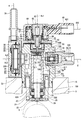
- the high-pressure pump 1 includes a housing 10, a plunger 20, a fuel chamber forming portion 30, an inlet portion 26, a pulsation damper 40, an intake valve portion 50, an electromagnetic drive portion 60, a discharge portion 70, a covered portion.
- a fixing portion 90 and the like are provided.
- the housing 10 is made of a metal such as stainless steel.
- the housing 10 includes a housing main body 11, a cylinder part 12, and a holder support part 13.
- the housing body 11 is formed in a substantially cylindrical shape.
- the cylinder portion 12 is formed in a substantially cylindrical shape and is provided in the center of the housing body 11. In the present embodiment, the cylinder portion 12 is formed integrally with the housing body 11.
- the holder support portion 13 is formed in a substantially cylindrical shape, and is provided on the housing body 11 so as to be coaxial with the cylinder portion 12 on the radially outer side of one end of the cylinder portion 12. In the present embodiment, the holder support portion 13 is formed integrally with the housing body 11.
- the housing body 11 has an inflow hole 101, a hole 102, a hole 105, a suction hole 106, a discharge hole 109, and a hole 108.
- the inflow hole portion 101 is formed so as to be recessed in a substantially cylindrical shape inward from the outer wall of the housing body 11 on the radially outer side of the cylinder portion 12. Specifically, it is formed so as to be recessed in a substantially cylindrical shape from the side wall of the housing main body 11, that is, the cylindrical outer wall of the housing main body 11 toward the inside.
- the hole 102 is formed so as to connect the inflow hole 101 and the space between the cylinder 12 and the holder support 13.
- a plurality of hole portions 102 are formed such that the axis is parallel to the axis of the cylinder portion 12.
- three hole portions 102 are formed so that the axis is parallel to the axis of the cylinder portion 12.
- parallel is not limited to two straight lines that are strictly parallel, but also includes two straight lines that are slightly non-parallel. same as below.
- the hole portion 105 is formed so as to connect the space between the cylinder portion 12 and the holder support portion 13 and the end surface of the housing body 11 opposite to the holder support portion 13.
- two holes 105 are formed such that the axis is parallel to the axis of the cylinder part 12.
- the suction hole portion 106 is formed so as to be recessed in a substantially cylindrical shape from the end surface of the housing body 11 opposite to the holder support portion 13 in the axial direction of the cylinder portion 12. Here, the suction hole portion 106 is connected to the space inside the cylinder portion 12.
- the discharge hole portion 109 is formed so as to be recessed in a substantially cylindrical shape inward from the outer wall of the housing body 11 on the radially outer side of the cylinder portion 12.
- the discharge hole 109 is formed on the side opposite to the inflow hole 101 with the axis of the cylinder 12 interposed therebetween.
- the hole 105 is formed so as to connect the space inside the cylinder 12 and the discharge hole 109.
- the plunger 20 is formed in a substantially cylindrical shape with a metal such as stainless steel.
- the plunger 20 has a large diameter part 201 and a small diameter part 202.
- the small diameter portion 202 is formed so that the outer diameter is smaller than the outer diameter of the large diameter portion 201.
- the large diameter portion 201 and the small diameter portion 202 are integrally formed coaxially.
- the plunger 20 is provided so that the large diameter part 201 side is inserted into the cylinder part 12.
- the outer diameter of the large-diameter portion 201 of the plunger 20 is substantially the same as the inner diameter of the cylinder portion 12 or slightly smaller than the inner diameter of the cylinder portion 12. Thereby, the outer wall of the large diameter part 201 slides on the inner wall of the cylinder part 12, and the plunger 20 is supported by the cylinder part 12 so that reciprocation is possible in an axial direction.
- a pressurizing chamber 107 is formed between the inner wall of the cylinder portion 12 and the end portion of the plunger 20 on the large diameter portion 201 side. That is, the cylinder part 12 has a pressurizing chamber 107 on the inner side. The volume of the pressurizing chamber 107 changes when the plunger 20 reciprocates inside the cylinder portion 12.
- the pressurizing chamber 107 is connected to the suction hole portion 106 and the hole portion 108.
- a seal holder 21 is provided inside the holder support portion 13.
- the seal holder 21 is formed in a cylindrical shape from a metal such as stainless steel.
- the seal holder 21 is provided such that the outer wall is fitted to the inner wall of the holder support portion 13.
- the seal holder 21 is provided so as to form a substantially cylindrical clearance between the inner wall at the end opposite to the cylinder portion 12 and the outer wall of the small diameter portion 202 of the plunger 20.
- An annular seal 22 is provided between the inner wall of the seal holder 21 and the outer wall of the small diameter portion 202 of the plunger 20.
- the seal 22 includes a fluorine resin ring on the inner diameter side and a rubber ring on the outer diameter side.
- the thickness of the fuel oil film around the small diameter portion 202 of the plunger 20 is adjusted by the seal 22, and fuel leakage to the engine 9 is suppressed.
- An oil seal 23 is provided at the end of the seal holder 21 opposite to the cylinder portion 12. The oil seal 23 adjusts the thickness of the oil film around the small-diameter portion 202 of the plunger 20, and prevents oil from entering the high-pressure pump 1.
- a variable volume chamber 104 whose volume changes when the plunger 20 reciprocates is formed between the step surface between the large diameter portion 201 and the small diameter portion 202 of the plunger 20 and the seal 22.
- annular space 103 which is an annular space is formed between the outer wall of the housing main body 11 and the cylinder portion 12, the inner wall of the holder support portion 13, and the seal holder 21.
- the annular space 103 is connected to the inflow hole portion 101 via the hole portion 102.
- the annular space 103 is connected to the end surface of the housing body 11 opposite to the holder support portion 13 via the hole portion 105.
- the annular space 103 is connected to the variable volume chamber 104 via a cylindrical space between the inner wall of the seal holder 21 and the outer wall of the cylinder portion 12.
- a substantially disc-shaped spring seat 24 is provided on the end of the plunger 20 opposite to the large diameter portion 201 of the small diameter portion 202.
- a spring 25 is provided between the seal holder 21 and the spring seat 24.
- the spring 25 is, for example, a coil spring, and is provided so that one end contacts the spring seat 24 and the other end contacts the seal holder 21.
- the spring 25 urges the plunger 20 to the side opposite to the pressurizing chamber 107 via the spring seat 24.
- the end of the plunger 20 opposite to the large diameter portion 201 of the small diameter portion 202 is in contact with the cam 5 of the cam shaft that rotates in conjunction with the drive shaft of the engine 9.
- the cam 5 of the cam shaft that rotates in conjunction with the drive shaft of the engine 9.
- the plunger 20 reciprocates in the axial direction by the rotation of the cam 5.
- the volumes of the pressurizing chamber 107 and the variable volume chamber 104 change periodically.
- the fuel chamber forming part 30 has a plate part 31, a cylinder part 32, a plate part 33, a cylinder part 34, and a support member 35.
- the plate part 31, the cylinder part 32, the plate part 33, the cylinder part 34, and the support member 35 are made of metal such as stainless steel, for example.
- the plate part 31 is formed in a substantially disc shape.
- the cylindrical portion 32 is formed integrally with the plate portion 31 so as to extend from the outer edge portion of the plate portion 31 in a substantially cylindrical shape.
- the plate portion 33 is formed in a substantially disc shape, and is provided so as to close the end portion of the cylindrical portion 32 on the side opposite to the plate portion 31.
- a fuel chamber 300 that is a flat circular space is formed between the plate portion 31, the cylinder portion 32, and the plate portion 33. That is, the fuel chamber forming part 30 is formed in a hollow disc shape.
- the plate portion 33 is formed separately from the tube portion 32.
- the cylindrical portion 34 is formed integrally with the plate portion 33 so as to extend in a substantially cylindrical shape from the center of the plate portion 33 to the side opposite to the plate portion 31. Thereby, the inside of the fuel chamber forming portion 30, that is, the fuel chamber 300 and the outside are connected via the space inside the cylinder portion 34.
- the support member 35 is provided in the fuel chamber 300.
- the fuel chamber forming portion 30 is provided in the housing 10 so that the cylindrical portion 34 fits into the inflow hole portion 101 of the housing main body 11. Thereby, the fuel chamber 300 and the inflow hole portion 101 are connected via the cylindrical portion 34.
- the fuel chamber forming portion 30 is fixed to the housing body 11 by welding, for example.
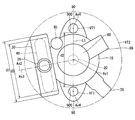
- the fuel chamber forming portion 30 is provided so that at least a part thereof is located outside the side wall of the housing body 11 of the housing 10 on the radially outer side of the plunger 20 (see FIGS. 2 and 3).
- the fuel chamber forming portion 30 is provided so that the axis Ax2 of the fuel chamber forming portion 30 is orthogonal to the axis Ax1 of the plunger 20 (see FIGS. 2 and 3).
- the expression “orthogonal” is not limited to two straight lines that are strictly orthogonal, but includes two straight lines that slightly incline and cross each other and two straight lines that are slightly separated from each other. same as below.
- the inlet portion 26 is formed in a substantially cylindrical shape with a metal such as stainless steel.
- the inlet portion 26 is connected to the cylindrical portion 32 of the fuel chamber forming portion 30 so that the shaft is parallel to the axis Ax1 of the plunger 20.
- the inside of the fuel chamber forming portion 30, that is, the fuel chamber 300 and the outside are connected via the space inside the inlet portion 26.
- the inlet 4 is connected to the pipe 4. As a result, the fuel discharged from the fuel pump 3 flows into the fuel chamber 300 via the inlet portion 26.
- the axial direction of the inlet part 26 can be freely set around the fuel chamber forming part 30, and the degree of freedom of mounting the high-pressure pump 1 is improved.
- the pulsation damper 40 is provided in the fuel chamber 300.
- the pulsation damper 40 is formed into a hollow disk shape by joining the peripheral portions of two diaphragms, for example, and a gas having a predetermined pressure is sealed inside.
- the pulsation damper 40 is supported by the support member 35 in the fuel chamber 300.
- the pulsation damper 40 is provided such that the axis Ax3 of the pulsation damper 40 is orthogonal to the axis Ax1 of the plunger 20 (see FIGS. 2 and 3). That is, in the present embodiment, the axis Ax2 of the fuel chamber forming portion 30 and the axis Ax3 of the pulsation damper 40 are substantially coincident.
- the pulsation damper 40 can reduce the pressure pulsation of the fuel by elastically deforming according to the change of the fuel pressure in the fuel chamber 300.
- a vibration suppressing member 41 is provided inside the pulsation damper 40.
- the vibration suppressing member 41 is formed in a substantially annular shape by an elastic member such as rubber.
- the vibration suppressing member 41 is in contact with the inner wall of the pulsation damper 40 at the outer edge.
- the vibration suppressing member 41 can suppress vibration generated when the pulsation damper 40 suppresses fuel pressure pulsation.
- the suction valve portion 50 is provided in the suction hole portion 106 of the housing body 11.
- the suction valve portion 50 includes a suction valve seat portion 51, a suction valve 52, a spring 53, a stopper 54, and a screwing portion 55.
- the suction hole portion 106 in which the suction valve portion 50 is provided is referred to as a suction passage 500.
- the suction valve seat 51 is formed in a substantially disc shape with a metal such as stainless steel, and is provided in the suction passage 500.
- the intake valve seat portion 51 has a plurality of holes that connect one end surface to the other end surface.
- a suction valve seat 511 is formed around the hole on the end surface of the suction valve seat 51 on the pressure chamber 107 side.
- the suction valve 52 is formed in a substantially disc shape with a metal such as stainless steel.
- the stopper 54 is formed in a substantially disk shape with a metal such as stainless steel, for example, and is provided on the pressurizing chamber 107 side with respect to the suction valve 52 so that the outer edge portion is fitted to the inner wall of the suction hole portion 106.
- the outer edge portion of the surface of the stopper 54 on the pressure chamber 107 side is in contact with the end surface of the cylinder portion 12 opposite to the seal holder 21.
- the outer edge portion of the stopper 54 opposite to the pressurizing chamber 107 is in contact with the conceptual portion of the suction valve seat portion 51.
- the stopper 54 has a plurality of holes that connect one surface to the other surface.
- the suction valve 52 is provided so as to be able to reciprocate between the suction valve seat 51 and the stopper 54. One end surface of the suction valve 52 can contact the suction valve seat 511. The suction valve 52 can open and close the suction passage 500 by being separated from the suction valve seat 511 or contacting the suction valve seat 511. That is, the intake valve 52 can open and close between the fuel chamber 300 and the pressurizing chamber 107.
- the other end face of the suction valve 52 can contact the stopper 54.
- the stopper 54 can restrict the movement of the suction valve 52 toward the pressurizing chamber 107 when the suction valve 52 abuts.
- the screwing portion 55 is formed in a substantially cylindrical shape with a metal such as stainless steel.
- a screw thread is formed on the outer wall of the screwing portion 55.
- a screw groove corresponding to the thread of the screwing portion 55 is formed in the inner wall of the suction hole portion 106.
- the screwing portion 55 is provided so as to be screwed into the screw groove of the suction hole portion 106. Accordingly, the screwing portion 55 presses the stopper 54 against the end surface of the cylinder portion 12 opposite to the seal holder 21 via the suction valve seat portion 51. That is, the suction valve seat 51 and the stopper 54 are fixed so as to be sandwiched between the screwing portion 55 and the cylinder portion 12.
- the screwing part 55 is provided coaxially with the plunger 20 (axis Ax1). Therefore, the influence which the distortion accompanying the screwing of the screwing part 55 has on the sliding part of the plunger 20 can be reduced.
- the spring 53 is a coil spring, for example, and is provided between the suction valve 52 and the stopper 54.
- the spring 53 biases the suction valve 52 toward the suction valve seat 511.
- the electromagnetic drive unit 60 is provided on the side opposite to the plunger 20 with respect to the suction valve unit 50.
- the electromagnetic drive unit 60 includes a yoke 61, a needle 62, a movable core 63, a cylindrical member 64, a fixed core 65, a spring 66, a coil 67, a yoke 68, and a connector 69.
- the yoke 61 is formed in a substantially disc shape by a magnetic material, for example.
- the yoke 61 is fixed to the housing body 11 with a gap s1 formed between the housing body 11 and the end surface opposite to the holder support portion 13. Thereby, the hole 105 and the suction passage 500 are connected via the gap s1.
- the needle 62 is formed in a rod shape from, for example, metal.
- the needle 62 is supported by a hole formed in the center of the yoke 61 so as to be reciprocally movable.
- One end of the needle 62 is inserted through a hole formed in the center of the suction valve seat 51, and can contact the end surface of the suction valve 52 opposite to the pressurizing chamber 107.
- the needle 62 is provided coaxially with the plunger 20.
- the movable core 63 is formed in a substantially cylindrical shape with, for example, a magnetic material, and is provided at the other end of the needle 62.
- the cylindrical member 64 is formed in a cylindrical shape from, for example, a nonmagnetic material, and is provided on the opposite side of the yoke 61 from the suction valve portion 50 on the radially outer side of the movable core 63.
- the fixed core 65 is made of, for example, a magnetic material, and is provided on the opposite side of the cylindrical member 64 from the yoke 61.
- the spring 66 is, for example, a coil spring, and is provided between the needle 62 and the fixed core 65.
- the spring 66 urges the needle 62 toward the pressurizing chamber 107.
- the biasing force of the spring 66 is set larger than the biasing force of the spring 53. Therefore, the suction valve 52 is separated from the suction valve seat 511.
- the coil 67 is formed in a substantially cylindrical shape, and is provided on the radially outer side of the cylindrical member 64 and the fixed core 65.
- the yoke 68 is formed, for example, in a cylindrical shape with a bottom using a magnetic material, and is provided so that the opening abuts against the yoke 61 while covering the coil 67.
- the connector 69 is formed to extend outward in the radial direction of the yoke 68.
- the connector 69 has a terminal 691.
- the terminal 691 is formed in a rod shape from an electrically conductive material, and one end thereof is electrically connected to the coil 67.
- a harness 692 is connected to the connector 69. As a result, power is supplied to the coil 67 via the harness 692 and the terminal 691.
- the electromagnetic drive unit 60 can drive the intake valve unit 50 so that the intake valve unit 50 opens and closes the intake passage 500 between the pressurizing chamber 107 and the fuel chamber 300 when energized.
- the electromagnetic drive unit 60 constitutes a so-called normally open type valve device that opens the intake valve 52 when not energized and closes the intake valve 52 when energized.
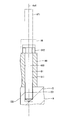
- the discharge part 70 is provided in the discharge hole 109 of the housing body 11.
- the discharge part 70 has a discharge cylinder part 71.
- the discharge cylinder portion 71 is formed in a substantially cylindrical shape with a metal such as stainless steel.
- the discharge cylinder 71 is provided in the housing body 11 so that one end thereof is screwed into the inner wall of the discharge hole 109.
- a discharge passage 700 is formed inside the discharge cylinder portion 71.
- a pipe 6 is connected to the other end of the discharge cylinder 71.
- a discharge valve portion 80 is provided in the discharge passage 700.
- the discharge valve portion 80 includes a discharge valve seat portion 81, a discharge valve 82, and a spring 83.
- the discharge valve seat part 81 is formed in a bottomed cylindrical shape with a metal such as stainless steel, for example, and is provided between the housing body 11 and the discharge cylinder part 71.
- the discharge valve seat 81 has a hole at the bottom.
- a discharge valve seat 811 is formed around the hole on the surface opposite to the pressurizing chamber 107 at the bottom of the discharge valve seat 81.
- the discharge valve 82 is formed, for example, in a substantially disk shape from a metal such as stainless steel, and is provided so as to be capable of reciprocating on the opposite side of the discharge valve seat 811 from the pressurizing chamber 107.
- One end surface of the discharge valve 82 can contact the discharge valve seat 811.
- the discharge valve 82 can open and close the discharge passage 700 by being separated from the discharge valve seat 811 or contacting the discharge valve seat 811. That is, the discharge valve 82 can open and close between the pressurizing chamber 107 and the pipe 6.
- the spring 83 is, for example, a coil spring, and biases the discharge valve 82 toward the discharge valve seat 811.
- the pressure of the fuel in the space on the pressurizing chamber 107 side relative to the discharge valve seat 81 is such that the fuel pressure in the space on the opposite side of the pressurizing chamber 107, that is, the space on the pipe 6 side, and the spring 83 are attached.
- the valve opening pressure of the discharge valve 82 When it becomes larger than the sum of the forces (the valve opening pressure of the discharge valve 82), the valve separates from the discharge valve seat 811 and opens. As a result, the fuel on the pressurizing chamber 107 side is discharged to the pipe 6 side via the discharge valve seat 811.
- the valve opening pressure of the discharge valve 82 can be set by adjusting the urging force of the spring 83.
- the fixed portion 90 is provided on the outer side of the outer wall of the housing body 11 in the radial direction of the plunger 20. Specifically, the fixed portion 90 is provided on the side wall of the housing body 11. In the present embodiment, the fixed portion 90 is formed of a metal such as stainless steel. The fixed portion 90 is formed integrally with the housing body 11 so as to protrude from the side wall of the housing body 11 to the radially outer side of the plunger 20. A plurality of fixed portions 90 are provided so as to have a line-symmetric relationship with the axis Ax1 of the plunger 20 as the axis of symmetry. Specifically, two fixed portions 90 are provided so as to have a line-symmetric relationship with the axis Ax1 of the plunger 20 as the axis of symmetry.
- the two fixed portions 90 are provided on the outer wall of the housing body 11 with the axis Ax1 of the plunger 20 interposed therebetween. In other words, two fixed portions 90 are provided at equal intervals (180 ° intervals) in the circumferential direction of the housing body 11.
- Each of the two fixed parts 90 has an insertion hole part 900.
- the insertion hole 900 is formed so that the axis Ax4 is parallel to the axis Ax1 of the plunger 20.
- the fixed portion 90 is fixed to the engine head 15 by a bolt 91 as a fixing member provided corresponding to the insertion hole portion 900.
- the bolt 91 as a fixing member has a shaft portion 911 and a head portion 912.
- the shaft portion 911 is formed in a substantially cylindrical shape, and a thread is formed on the outer wall of one end portion.
- the head 912 is formed in a hexagonal column shape, for example, and is provided at the other end of the shaft portion 911.
- a fixed hole 151 is formed in the engine head 15.
- the fixing hole 151 is formed so that its axis is substantially parallel to the axis of the mounting hole 150.
- a thread groove corresponding to the thread of the shaft portion 911 of the bolt 91 is formed on the inner wall of the fixing hole 151.
- the bolt 91 has a shaft portion 911 inserted through the insertion hole portion 900 of the fixed portion 90, and one end portion is screwed into the fixing hole portion 151 of the engine head 15.
- the fixed portion 90 can be sandwiched and fixed (see FIG. 4). Thereby, the high-pressure pump 1 can be fixed to the engine 9.
- the fuel chamber forming portion 30 defines the virtual cylindrical surface VT ⁇ b> 1 including all of the axis Ax ⁇ b> 4 of the insertion hole 900 and the inner wall of the insertion hole 900 as the plunger 20. It is provided at a position avoided in the radially outward direction. That is, the axis Ax4 and the virtual cylindrical surface VT1 do not pass through the fuel chamber forming portion 30 and the pulsation damper 40, and the fuel chamber forming portion 30, the axis Ax4 and the virtual cylindrical surface VT1 are separated by a predetermined distance or more. .
- the fuel chamber forming portion 30 is provided at a position avoiding the straight line L1 connecting the axes Ax4 of the two insertion hole portions 900. That is, the fuel chamber forming portion 30 and the pulsation damper 40 are not provided between the two insertion hole portions 900.
- the straight line L1 passes through the axis Ax1 of the plunger 20.
- the fuel chamber forming portion 30 has an outer diameter d1 larger than the distance d2 between the two insertion holes 900.
- the outer diameter d3 of the pulsation damper 40 is slightly smaller than the distance d2 between the two insertion holes 900.
- the electromagnetic drive unit 60 is provided on the axis Ax1 of the plunger 20 at a position avoiding the axis Ax4 and the virtual cylindrical surface VT1. Note that the needle 62, the movable core 63, the fixed core 65, and the coil 67 of the electromagnetic drive unit 60 are provided so that their axes substantially coincide with the axis Ax1 of the plunger 20 (see FIG. 2).
- the connector 69 is provided so as to face the same direction as the discharge unit 70. Moreover, the inlet part 26, the discharge part 70, and the connector 69 are provided in the position which avoided the axis
- the suction valve unit 50 and the electromagnetic drive unit 60 are provided on the shaft of the plunger 20 and the suction valve 52 is disposed as close as possible to the pressurization chamber 107, thereby connecting to the pressurization chamber 107.
- the volume can be made relatively small. Thereby, fuel can be effectively pressurized.
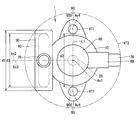
- the holder support 13 of the housing 10 is inserted into the mounting hole 150 of the engine head 15.
- the insertion hole 900 of the fixed portion 90 is aligned with the fixing hole 151 of the engine head 15 (see FIG. 4).
- the bolt 91 is inserted into the insertion hole 900, and the bolt 91 is screwed into the fixing hole 151 with the tool 16.
- the fixed part 90 is fixed to the engine head 15, and the attachment to the engine 9 of the high-pressure pump 1 is completed.
- the tool 16 since the fuel chamber forming portion 30, the inlet portion 26, the discharge portion 70, the connector 69, and the like are provided at positions avoiding the axis Ax4 and the virtual cylindrical surface VT1, the tool 16 does not interfere.
- the bolt 91 can be easily screwed in.
- fuel in the fuel chamber 300 can flow into the inflow hole portion 101, fuel in the inflow hole portion 101 can flow into the hole portion 102, and fuel in the hole portion 102 can flow into the annular space 103.
- the fuel in the annular space 103 can flow into the hole 105, the fuel in the hole 105 can flow into the gap s1, and the fuel in the gap s1 can flow into the suction passage 500.
- the fuel can flow into the pressurizing chamber 107.
- the amount of fuel returned from the pressurizing chamber 107 to the suction passage 500 side is adjusted by adjusting the timing for closing the suction valve 52. As a result, the amount of fuel pressurized in the pressurizing chamber 107 is determined.
- the intake valve 52 is closed, the metering process for returning the fuel from the pressurizing chamber 107 to the intake passage 500 is completed.
- the fuel in the pressurizing chamber 107 can flow out into the suction passage 500, the fuel in the suction passage 500 can flow out into the gap s1, and the fuel in the gap s1 can flow out into the hole 105.
- the fuel in the hole portion 105 can flow out into the annular space 103, the fuel in the annular space 103 can flow out into the hole portion 102, the fuel in the hole portion 102 can flow out into the inflow hole portion 101, and the inflow hole portion.
- the fuel 101 can flow into the fuel chamber 300.
- the high pressure pump 1 pressurizes and discharges the fuel in the sucked fuel tank 2 and supplies it to the fuel rail 7 by repeating the above “suction process”, “metering process”, and “pressurization process”.
- the amount of fuel supplied from the high-pressure pump 1 to the fuel rail 7 is adjusted by controlling the power supply timing to the coil 67 of the electromagnetic drive unit 60 and the like.
- pressure pulsation may occur in the fuel in the fuel chamber 300.
- the pulsation damper 40 provided in the fuel chamber 300 can be elastically deformed according to the change in the fuel pressure in the fuel chamber 300, thereby reducing the pressure pulsation of the fuel in the fuel chamber 300.
- the fuel that has flowed from the inlet portion 26 flows into the fuel chamber 300, the inflow hole portion 101, the hole portion 102, the annular space 103, the hole portion. 105, the space between the housing body 11 and the yoke 61 flows through the suction passage 500 to the pressurizing chamber 107. Further, when the plunger 20 reciprocates, the volume of the variable volume chamber 104 increases or decreases, so that fuel flows between the annular space 103 and the variable volume chamber 104.
- the cylinder part 12 and the plunger 20 that have become high temperature due to heat generated by sliding between the plunger 20 and the cylinder part 12 and heat generated by pressurizing the fuel in the pressurizing chamber 107 are cooled by the low-temperature fuel. Can do. Thereby, the burn-in of the plunger 20 and the cylinder part 12 can be suppressed.
- part of the fuel that has become high pressure in the pressurizing chamber 107 flows into the variable volume chamber 104 via the clearance between the plunger 20 and the cylinder portion 12.
- an oil film is formed between the plunger 20 and the cylinder part 12, and the seizure of the plunger 20 and the cylinder part 12 can be effectively suppressed.
- the fuel that has flowed into the variable volume chamber 104 from the pressurizing chamber 107 flows into the pressurizing chamber 107 again via the annular space 103, the hole 105, and the suction passage 500.
- this embodiment is a high-pressure pump 1 that is attached to an engine 9, pressurizes and discharges fuel, and supplies the engine 9 with a housing 10, a plunger 20, a fuel chamber forming portion 30, and The pulsation damper 40, the discharge part 70, and the to-be-fixed part 90 are provided.
- the housing 10 has a pressurizing chamber 107.
- the plunger 20 moves to increase or decrease the volume of the pressurizing chamber 107, and can pressurize the fuel in the pressurizing chamber 107.
- the fuel chamber forming portion 30 is provided on the radially outer side of the plunger 20 and forms a fuel chamber 300 communicating with the pressurizing chamber 107.
- the pulsation damper 40 is provided in the fuel chamber 300 and can reduce the pressure pulsation of the fuel in the fuel chamber 300.
- the discharge unit 70 discharges the fuel pressurized in the pressurizing chamber 107.
- the fixed portion 90 is provided on the outer wall of the outer wall of the housing 10 in the radial direction of the plunger 20.
- the shaft Ax 4 has an insertion hole 900 parallel to the axis Ax 1 of the plunger 20, and is provided corresponding to the insertion hole 900.
- the bolt 9 is fixed to the engine 9.
- the fuel chamber formation part 30 is provided in the position which avoided the axis
- the fuel chamber forming portion 30 is provided on the radially outer side of the plunger 20, it is possible to increase the size while avoiding the axis Ax4 of the insertion hole portion 900. Therefore, the size of the pulsation damper 40 can be increased while suppressing the interference between the tool 16 and the fuel chamber forming portion 30 when the fixed portion 90 is fixed by the bolt 91, and the pulsation reduction effect of the fuel in the fuel chamber 300 is enhanced. be able to.
- the fuel chamber forming portion 30 is provided at a position avoiding the axis Ax4 of the insertion hole 900 on the radially outer side of the plunger 20, and therefore the insertion hole 900 is connected to the axis Ax1 of the plunger 20. It can be formed in a close position. Therefore, the physique of the high-pressure pump 1 including the fixed portion 90 in which the insertion hole portion 900 is formed can be reduced.
- the fuel chamber forming portion 30 is provided at a position avoiding the virtual cylindrical surface VT1 including the entire inner wall of the insertion hole portion 900. Therefore, it is possible to more effectively suppress the tool 16 used when the fixed portion 90 of the high-pressure pump 1 is fixed to the engine 9 by the bolt 91 from interfering with the fuel chamber forming portion 30.
- the bolt 91 is inserted into the insertion hole 900 and fixed to the engine 9, whereby the fixed portion 90 can be fixed to the engine 9.
- the pulsation damper 40 is formed in a hollow disk shape, and is provided so that the axis Ax3 intersects the axis Ax1 of the plunger 20.
- the pulsation damper 40 is provided so that the axis Ax3 is orthogonal to the axis Ax1 of the plunger 20.
- two insertion holes 900 are provided so as to have a line-symmetric relationship with the axis Ax1 of the plunger 20 as the axis of symmetry.
- the fuel chamber forming portion 30 is provided at a position avoiding the axis Ax4 of the insertion hole 900, two insertion holes 900 are provided so as to be line-symmetric with respect to the axis Ax1 of the plunger 20. Even if it is the structure by which the fuel chamber 300 and pulse
- the physique of the session damper 40 can be enlarged.
- the fuel chamber forming portion 30 is formed in a hollow disk shape, and the outer diameter d1 is larger than the distance d2 between the two insertion hole portions 900. Therefore, it is possible to increase the physique of the pulsation damper 40 while suppressing an increase in the physique of the high-pressure pump 1 including the fixed portion 90 in which the insertion hole 900 is formed, and to reduce the fuel pulsation in the fuel chamber 300 Can be increased.
- the present embodiment further includes a cylindrical inlet portion 26 that communicates with the fuel chamber 300 and guides fuel from the outside to the fuel chamber 300.
- the inlet portion 26 is connected to the fuel chamber forming portion 30. This exemplifies a specific configuration of the present embodiment.
- the inlet portion 26 is provided at a position avoiding the axis Ax4 of the insertion hole portion 900 and the virtual cylindrical surface VT1. Therefore, it is possible to prevent the tool 16 used when the fixed portion 90 of the high-pressure pump 1 is fixed to the engine 9 with the bolt 91 from interfering with the inlet portion 26. Thereby, attachment to the engine 9 of the high pressure pump 1 becomes easy.
- the inlet portion 26 is provided. Is easily connected to the fuel chamber forming portion 30 while avoiding the axis Ax4 of the insertion hole portion 900. Therefore, the connection position of the inlet portion 26 with respect to the fuel chamber forming portion 30 and the degree of freedom in the connection direction are improved.
- the present embodiment further includes a suction valve unit 50 and an electromagnetic drive unit 60.
- the suction valve unit 50 can open and close between the pressurizing chamber 107 and the fuel chamber 300.
- the electromagnetic drive unit 60 can drive the intake valve unit 50 so that the intake valve unit 50 opens and closes between the pressurizing chamber 107 and the fuel chamber 300 when energized.
- the electromagnetic drive unit 60 is provided at a position avoiding the axis Ax4 of the insertion hole 900 and the virtual cylindrical surface VT1. Therefore, it is possible to prevent the tool 16 used when the fixed portion 90 of the high-pressure pump 1 is fixed to the engine 9 with the bolt 91 from interfering with the electromagnetic drive portion 60. Thereby, attachment to the engine 9 of the high pressure pump 1 becomes easy.
- the electromagnetic drive unit 60 is provided on the axis Ax1 of the plunger 20. This exemplifies a specific configuration of the present embodiment.
- the electromagnetic drive unit 60 has a connector 69 to which a harness 692 for energization is connected.
- the connector 69 is provided at a position avoiding the axis Ax4 of the insertion hole 900 and the virtual cylindrical surface VT1. Therefore, it is possible to prevent the tool 16 used when the fixed portion 90 of the high-pressure pump 1 is fixed to the engine 9 by the bolt 91 from interfering with the connector 69. Thereby, attachment to the engine 9 of the high pressure pump 1 becomes easy.
- FIG. 1st Embodiment A part of the high-pressure pump according to the second embodiment of the present disclosure is shown in FIG. In 2nd Embodiment, the structure of the fixing member which fixes the to-be-fixed part 90 to the engine 9 differs from 1st Embodiment.
- the shaft portion 152 is formed on the engine head 15 of the engine 9.
- the shaft portion 152 is formed integrally with the engine head 15 so as to extend from the engine head 15 in a substantially cylindrical shape.
- the shaft portion 152 is formed so that the shaft is substantially parallel to the shaft of the mounting hole 150.
- a thread is formed on the outer wall of the end portion of the shaft portion 152 opposite to the engine head 15.
- the fixed portion 90 is fixed to the engine head 15 by a nut 92 as a fixing member provided corresponding to the insertion hole portion 900.
- the nut 92 is formed in a hexagonal column shape, and a hole 921 is formed in the center.
- a thread groove corresponding to the thread of the shaft portion 152 is formed on the inner wall of the hole portion 921.
- the nut 92 is screwed into the shaft portion 152 inserted through the insertion hole portion 900 of the fixed portion 90, so that the fixed portion 90 can be sandwiched between the engine head 15 and fixed (see FIG. 6). Thereby, the high-pressure pump can be fixed to the engine 9.
- the second embodiment is the same as the first embodiment except for the points described above.
- the nut 92 as the fixing member is fixed to the shaft portion 152 that is a part of the engine 9 inserted through the insertion hole portion 900, thereby fixing the fixed portion.
- 90 can be fixed to the engine 9. This specifically illustrates the configuration of a fixing member used when fixing the fixed portion 90 to the engine 9.
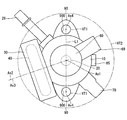
- FIG. 30 A high-pressure pump according to a third embodiment of the present disclosure is shown in FIG.
- the arrangement of the fuel chamber forming unit 30 is different from that of the first embodiment.
- the third embodiment further includes a relief valve portion 85.
- the relief valve portion 85 is provided on the outer wall of the housing body 11 of the housing 10. In the present embodiment, the relief valve portion 85 is provided so as to protrude from the outer wall of the housing body 11 in a direction substantially parallel to the axis Ax1 of the plunger 20.
- the relief valve portion 85 has a relief valve (not shown).
- the relief valve has a discharge valve seat 811 inside the discharge cylinder portion 71 of the discharge portion 70 on the side opposite to the pressurizing chamber 107 and a gap s1 (see FIG. 2) between the housing body 11 and the yoke 61. The passage connecting the two can be opened and closed.
- the relief valve 85 opens when the fuel pressure on the side opposite to the pressurizing chamber 107 with respect to the discharge valve seat 811 inside the discharge cylinder portion 71 of the discharge portion 70 becomes a predetermined value or more.
- the fuel can be released to the gap s1 between the housing body 11 and the yoke 61. Therefore, it is possible to suppress the fuel pressure on the side opposite to the pressurizing chamber 107 from becoming excessive with respect to the discharge valve seat 811 inside the discharge cylinder portion 71 of the discharge portion 70. Thereby, damage etc. of piping 6 connected to discharge part 70 can be controlled.
- the high pressure fuel when the relief valve is opened, the high pressure fuel is allowed to escape into the gap s1 that is relatively close to the pressurizing chamber 107. Therefore, compared to the configuration in which the high pressure fuel is allowed to escape into the fuel chamber 300, for example, the pipe 4 Moreover, the influence of the fuel pressure on the members provided in the low pressure environment such as the fuel pump 3 can be reduced.
- the relief valve portion 85 is provided at a position avoiding the axis Ax4 of the insertion hole portion 900 and the virtual cylindrical surface VT1.
- the fuel chamber forming portion 30, the discharge portion 70, and the connector 69 are positions shifted in the circumferential direction of the housing main body 11 as compared with the first embodiment, respectively, and have an axis Ax4 and a virtual cylindrical shape. It is provided at a position avoiding the surface VT1.
- the discharge part 70 and the connector 69 are provided so as to face different directions.
- the third embodiment is the same as the first embodiment except for the points described above.
- the present embodiment further includes a relief valve portion 85.
- the relief valve unit 85 can release the fuel in the discharge unit 70 toward the pressurizing chamber 107 with respect to the discharge unit 70 when the pressure of the fuel in the discharge unit 70 becomes a predetermined value or more. Thereby, damage etc. of piping 6 connected to discharge part 70 can be controlled.
- the relief valve portion 85 is provided at a position avoiding the axis Ax4 of the insertion hole portion 900 and the virtual cylindrical surface VT1. Therefore, it is possible to prevent the tool 16 used when the fixed portion 90 of the high-pressure pump is fixed to the engine 9 with the bolt 91 from interfering with the relief valve portion 85. Thereby, attachment to the engine 9 of a high pressure pump becomes easy.
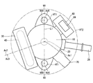
- FIG. 4 A high-pressure pump according to a fourth embodiment of the present disclosure is shown in FIG.
- the fourth embodiment is different from the third embodiment in the arrangement of the relief valve portion 85 and the inlet portion 26.
- the relief valve portion 85 is provided so as to protrude radially outward from the outer wall of the housing body 11 of the housing 10.
- the relief valve portion 85 is provided on a virtual plane that passes through the discharge portion 70 and is orthogonal to the axis Ax1 of the plunger 20.
- the inlet portion 26 is provided so as to be connected to the outer wall of the housing body 11.
- the space inside the inlet portion 26 communicates with, for example, the inflow hole portion 101 of the housing body 11.
- the relief valve portion 85 and the inlet portion 26 are provided at positions avoiding the axis Ax4 of the insertion hole portion 900 and the virtual cylindrical surface VT1.
- the inlet part 26 is provided so that the edge part on the opposite side to the housing main body 11 may be located in the outer side of the virtual cylindrical surface VT2.
- the fourth embodiment is the same as the third embodiment except for the points described above.
- the inlet portion 26 is connected to the housing 10. This exemplifies a specific configuration of the present embodiment.
- the inlet portion 26 is provided at a position avoiding the axis Ax4 of the insertion hole portion 900 and the virtual cylindrical surface VT1.
- the relief valve portion 85 is provided at a position avoiding the axis Ax4 of the insertion hole 900 and the virtual cylindrical surface VT1. Therefore, it is possible to prevent the tool 16 used when the fixed portion 90 of the high-pressure pump is fixed to the engine 9 with the bolt 91 from interfering with the inlet portion 26 and the relief valve portion 85. Thereby, attachment to the engine 9 of a high pressure pump becomes easy.
- FIG. 5 A high-pressure pump according to a fifth embodiment of the present disclosure is shown in FIG.
- the fifth embodiment differs from the fourth embodiment in the arrangement of the electromagnetic drive unit 60 and the inlet unit 26.
- the electromagnetic drive unit 60 is provided so as to protrude radially outward from the outer wall of the housing body 11 of the housing 10.
- the connector 69 is provided so as to face a direction substantially parallel to the axis Ax1 of the plunger 20.
- the inlet portion 26 is provided so as to be connected between the electromagnetic drive portion 60 and the discharge portion 70 on the outer wall of the housing body 11.
- the electromagnetic drive part 60, the connector 69, and the inlet part 26 are provided at positions avoiding the axis Ax4 of the insertion hole 900 and the virtual cylindrical surface VT1.
- the fifth embodiment does not include the relief valve portion 85 shown in the fourth embodiment.
- the fifth embodiment is the same as the fourth embodiment except for the points described above.
- FIG. 6 A high-pressure pump according to a sixth embodiment of the present disclosure is shown in FIG.
- the sixth embodiment is different from the fourth embodiment in the arrangement of the electromagnetic drive unit 60.
- the electromagnetic drive unit 60 is provided so as to protrude radially outward from the outer wall of the housing body 11 of the housing 10 as in the fifth embodiment.
- the connector 69 is provided so as to face a direction substantially parallel to the axis Ax1 of the plunger 20 as in the fifth embodiment.
- the electromagnetic drive part 60 is provided between the relief valve part 85 and the fixed part 90 on the outer wall of the housing body 11.
- the sixth embodiment is the same as the fourth embodiment except for the points described above.
- FIG. 7 A high-pressure pump according to a seventh embodiment of the present disclosure is shown in FIG.
- the seventh embodiment differs from the sixth embodiment in the orientation of the connector 69 of the electromagnetic drive unit 60.
- the connector 69 of the electromagnetic drive unit 60 is provided so as to face the direction of twisting with respect to the axis Ax1 of the plunger 20.
- the angle formed between the straight line L2 along the direction in which the connector 69 faces and the axis Ax1 is substantially a right angle. Further, the straight line L2 and the axis of the inlet portion 26 are substantially parallel.
- the seventh embodiment is the same as the sixth embodiment except for the points described above.
- FIG. 8 A high-pressure pump according to an eighth embodiment of the present disclosure is shown in FIG.
- the sizes of the fuel chamber forming portion 30 and the pulsation damper 40 are different from those of the third embodiment.
- the fuel chamber forming portion 30 has an outer diameter d1 larger than the distance d2 between the two insertion hole portions 900. Further, the outer diameter d3 of the pulsation damper 40 is larger than the distance d2 between the two insertion holes 900.
- a part of the fuel chamber forming portion 30 and the pulsation damper 40 are located outside the virtual cylindrical surface VT2 passing through the end portion of the discharge portion 70 with the axis Ax1 of the plunger 20 as the center.
- the eighth embodiment is the same as the third embodiment except for the points described above.
- the outer diameter d1 of the fuel chamber forming portion 30 and the outer diameter d3 of the pulsation damper 40 are larger than the distance d2 between the two insertion hole portions 900. Therefore, compared with the third embodiment, the effect of reducing the pulsation of fuel in the fuel chamber 300 by the pulsation damper 40 can be enhanced.
- FIG. 9 A high-pressure pump according to a ninth embodiment of the present disclosure is shown in FIG.
- the ninth embodiment differs from the first embodiment in the configuration of the housing 10 and the fuel chamber forming portion 30.
- the cylinder portion 12 is formed separately from the housing body 11.
- the cylinder portion 12 is formed in a substantially cylindrical shape, and is provided so that the outer wall is fitted to the inner wall of the housing body 11.
- the plate part 31 is formed separately from the cylindrical part 32.
- the cylinder portion 32 is formed integrally with the plate portion 33.
- the plate part 31 is provided so as to block the side of the cylinder part 32 opposite to the cylinder part 34.
- the ninth embodiment is the same as the first embodiment except for the points described above.
- FIG. 10th Embodiment A high-pressure pump according to a tenth embodiment of the present disclosure is shown in FIG.
- the tenth embodiment differs from the first embodiment in the configuration of the fixed portion 90 and the like.
- the fixed portion 90 is formed separately from the housing body 11.
- the end surface of the fixed portion 90 opposite to the engine head 15 is formed so as to be positioned on the engine head 15 side with respect to the axis Ax2 of the fuel chamber forming portion 30, for example.
- the tenth embodiment is the same as the first embodiment except for the points described above.
- the fuel chamber forming portion 30 may be provided at a position through which the virtual cylindrical surface VT1 passes as long as the position avoids the axis Ax4 of the insertion hole portion 900.
- the pulsation damper 40 may be provided such that the axis Ax3 intersects the axis Ax1 of the plunger 20 with an inclination. Further, the pulsation damper 40 may be provided such that the axis Ax3 is twisted with the axis Ax1 of the plunger 20. In this case, the pulsation damper 40 may be provided such that the axis Ax3 is twisted at a right angle to the axis Ax1 of the plunger 20. That is, at this time, the angle formed by the axis Ax3 of the pulsation damper 40 and the axis Ax1 of the plunger 20 is a right angle. Note that the angle formed by the two straight lines having a twist relationship corresponds to the angle formed by two half lines extending in parallel to the two straight lines starting from an arbitrary point.
- the outer diameter d1 of the fuel chamber forming portion 30 may be smaller than the distance d2 between the two insertion hole portions 900.
- four or more insertion holes 900 may be provided so as to have a line-symmetric relationship with the axis Ax1 of the plunger 20 as the axis of symmetry. Further, three or more insertion holes 900 may be provided at equal intervals in the circumferential direction of the plunger 20.
- the inlet portion 26 is connected to the fuel chamber forming portion 30 so that the shaft is substantially parallel to the axis Ax1 of the plunger 20 has been described.
- the inlet portion 26 is connected to the fuel chamber forming portion 30 in any orientation in consideration of the mounting space of the high-pressure pump in the vehicle, the position of the piping 4, and the like. May be.
- the discharge part 70 and the inlet part 26 may be connected to the housing body 11 in any orientation in consideration of the mounting space of the high-pressure pump in the vehicle, the positions of the pipes 4 and 6, and the like. Further, the inlet portion 26 may be omitted.
- the connector 69 of the electromagnetic drive unit 60 may be provided so as to face in any direction with respect to the housing body 11 in consideration of the space for mounting the high-pressure pump on the vehicle, the position of the harness 692, and the like.
- the relief valve portion 85 supplies the fuel on the side opposite to the pressurizing chamber 107 with respect to the discharge valve seat 811 inside the discharge cylinder portion 71 of the discharge portion 70, and the housing body 11 and the yoke 61.
- the example which escapes to the clearance gap s1 between was shown.
- the relief valve portion 85 allows fuel inside the discharge cylinder portion 71 of the discharge portion 70 to flow between the intake valve 52 and the discharge valve 82 that have a relatively high pressure, for example. It is also possible to escape to the space including the pressurizing chamber 107 or the inflow hole portion 101 and the fuel chamber 300 which are at a relatively low pressure.
- the vibration suppressing member 41 inside the pulsation damper 40 may be omitted.
- the fuel chamber forming portion 30 may be formed integrally with the housing body 11.
- the high-pressure pump may be used as a fuel pump that discharges fuel toward a device other than the engine of the vehicle.
Abstract
ハウジング(10)は、加圧室(107)を有している。プランジャ(20)は、加圧室(107)の容積を増減するよう移動し、加圧室(107)内の燃料を加圧可能である。燃料室形成部(30)は、プランジャ(20)の径方向外側に設けられ、加圧室(107)に連通する燃料室(300)を形成している。パルセーションダンパ(40)は、燃料室(300)内に設けられ、燃料室(300)内の燃料の圧力脈動を低減可能である。被固定部(90)は、プランジャ(20)の径方向外側に設けられ、挿通穴部(900)を有し、挿通穴部(900)に対応して設けられるボルト(91)によりエンジン(9)に固定される。燃料室形成部(30)は、挿通穴部(900)の軸(Ax4)を避けた位置に設けられている。
Description
本願は、2016年4月28日に出願された日本国特許出願第2016-90327号に基づくものであり、この開示をもってその内容を本明細書中に開示したものとする。
本開示は、燃料を加圧し吐出する高圧ポンプに関する。
従来、内燃機関に取り付けられ、プランジャで燃料を加圧し内燃機関に供給する高圧ポンプが知られている。例えば特許文献1の高圧ポンプは、ハウジングの外壁からプランジャの径方向外側へ延びるよう形成され、内燃機関に固定される被固定部を備えている。当該被固定部は、軸がプランジャの軸に対し平行な挿通穴部を有している。そして、固定部材を挿通穴部に挿通し内燃機関にねじ込んで固定することで、被固定部を内燃機関に固定している。
ところで、特許文献1の高圧ポンプは、加圧室に連通する燃料室内にパルセーションダンパを設け、燃料室内の燃料の脈動の低減を図っている。ここで、燃料室およびパルセーションダンパは、プランジャの軸上に位置している。また、パルセーションダンパは、中空の円板状に形成され、軸がプランジャの軸に対し平行となるよう設けられている。また、上記被固定部の挿通穴部は、プランジャの軸を対称軸として線対称となるよう2つ形成されている。そのため、燃料室を形成する部位である燃料室形成部、または、パルセーションダンパの外径が2つの挿通穴部間の距離より大きい場合、固定部材を内燃機関にねじ込むときに使用する工具が燃料室形成部に干渉し、高圧ポンプの内燃機関への取り付けが困難になるおそれがある。
そこで、工具が燃料室形成部に干渉しないよう燃料室形成部の外径を小さくした場合、パルセーションダンパの外径を小さくしなければならず、十分な脈動低減効果を奏することができなくなるおそれがある。一方、十分な脈動低減効果を奏するためにパルセーションダンパの外径を大きくした場合、燃料室形成部の外径も大きくなり、2つの挿通穴部間の距離を大きくしなければならなくなる。これにより、高圧ポンプが大型化するおそれがある。
本開示は、上述の問題に鑑みてなされたものであり、その目的は、燃料室内の燃料の脈動低減効果が高く、内燃機関への取り付けが容易な小型の高圧ポンプを提供することにある。
本開示は、内燃機関に取り付けられ、燃料を加圧し吐出し内燃機関に供給する高圧ポンプであって、ハウジングとプランジャと燃料室形成部とパルセーションダンパと吐出部と被固定部とを備えている。
ハウジングは、加圧室を有している。
プランジャは、加圧室の容積を増減するよう移動し、加圧室内の燃料を加圧可能である。
燃料室形成部は、プランジャの径方向外側に設けられ、加圧室に連通する燃料室を形成している。
パルセーションダンパは、燃料室内に設けられ、燃料室内の燃料の圧力脈動を低減可能である。
吐出部は、加圧室で加圧された燃料を吐出する。
被固定部は、プランジャの径方向外側に設けられ、挿通穴部を有し、挿通穴部に対応して設けられる固定部材により内燃機関に固定される。
そして、本開示では、燃料室形成部は、挿通穴部の軸を避けた位置に設けられている。そのため、固定部材により高圧ポンプの被固定部を内燃機関に固定するときに使用する工具が燃料室形成部に干渉するのを抑制することができる。これにより、高圧ポンプの内燃機関への取り付けが容易になる。
また、本開示では、燃料室形成部は、プランジャの径方向外側に設けられているため、燃料室形成部を大きくしても挿通穴部の軸に干渉しにくい。そのため、本開示では、挿通穴部の軸を避けつつ燃料室形成部の体格を大きくすることが可能である。したがって、固定部材による被固定部の固定時の工具と燃料室形成部との干渉を抑えながら、パルセーションダンパの体格を大きくでき、燃料室内の燃料の脈動低減効果を高めることができる。
また、本開示では、燃料室形成部が、プランジャの径方向外側において挿通穴部の軸を避けた位置に設けられているため、挿通穴部をプランジャの軸に対し比較的近い位置に形成することができる。そのため、挿通穴部が形成される被固定部を含む高圧ポンプの体格を小さくすることができる。
なお、燃料室形成部を、挿通穴部の内壁を全て含む仮想筒状面を避けた位置に設けた場合、固定部材により高圧ポンプの被固定部を内燃機関に固定するときに使用する工具が燃料室形成部に干渉するのをより効果的に抑制することができる。
本開示についての上記目的およびその他の目的、特徴や利点は、添付の図面を参照しながら下記の詳細な記述により、より明確になる。
以下、本開示の複数の実施形態による高圧ポンプを図面に基づき説明する。なお、複数の実施形態において実質的に同一の構成部位には同一の符号を付し、説明を省略する。また、複数の実施形態において実質的に同一の構成部位は、同一または同様の作用効果を奏する。
(第1実施形態)
本開示の第1実施形態による高圧ポンプを図2、3に示す。
本開示の第1実施形態による高圧ポンプを図2、3に示す。
高圧ポンプ1は、図示しない車両に設けられる。高圧ポンプ1は、例えば内燃機関としてのエンジン9に、燃料を高圧で供給するポンプである。高圧ポンプ1がエンジン9に供給する燃料は、例えばガソリンである。すなわち、高圧ポンプ1の燃料供給対象は、ガソリンエンジンである。
図1に示すように、燃料タンク2に貯留された燃料は、燃料ポンプ3により配管4を経由して高圧ポンプ1に供給される。高圧ポンプ1は、燃料ポンプ3から供給された燃料を加圧し、配管6を経由して燃料レール7に吐出する。これにより、燃料レール7内の燃料は、蓄圧され、燃料レール7に接続する燃料噴射弁8からエンジン9に噴射供給される。
図2、3に示すように、高圧ポンプ1は、ハウジング10、プランジャ20、燃料室形成部30、インレット部26、パルセーションダンパ40、吸入弁部50、電磁駆動部60、吐出部70、被固定部90等を備えている。
ハウジング10は、例えばステンレス等の金属により形成されている。ハウジング10は、ハウジング本体11、シリンダ部12、ホルダ支持部13を有している。
ハウジング本体11は、略円筒状に形成されている。シリンダ部12は、略円筒状に形成され、ハウジング本体11の中央に設けられている。本実施形態では、シリンダ部12は、ハウジング本体11と一体に形成されている。
ホルダ支持部13は、略円筒状に形成され、シリンダ部12の一端の径方向外側においてシリンダ部12と同軸となるようハウジング本体11に設けられている。本実施形態では、ホルダ支持部13は、ハウジング本体11と一体に形成されている。
ハウジング本体11は、流入穴部101、穴部102、穴部105、吸入穴部106、吐出穴部109、穴部108を有している。
流入穴部101は、シリンダ部12の径方向外側において、ハウジング本体11の外壁から内側に略円筒状に凹むようにして形成されている。具体的には、ハウジング本体11の側壁、すなわち、ハウジング本体11の円筒面状の外壁から内側に向かって略円筒状に凹むようにして形成されている。
穴部102は、流入穴部101と、シリンダ部12とホルダ支持部13との間の空間とを接続するよう形成されている。本実施形態では、穴部102は、軸がシリンダ部12の軸と平行になるよう複数形成されている。具体的には、穴部102は、軸がシリンダ部12の軸と平行になるよう3つ形成されている。ここで、「平行」との表現は、厳密に平行となる2直線に限らず、わずかに非平行となる2直線も含むものとする。以下、同じ。
穴部105は、シリンダ部12とホルダ支持部13との間の空間と、ハウジング本体11のホルダ支持部13とは反対側の端面とを接続するよう形成されている。本実施形態では、穴部105は、軸がシリンダ部12の軸と平行になるよう2つ形成されている。
吸入穴部106は、シリンダ部12の軸方向において、ハウジング本体11のホルダ支持部13とは反対側の端面から略円筒状に凹むようにして形成されている。ここで、吸入穴部106は、シリンダ部12の内側の空間に接続している。
吐出穴部109は、シリンダ部12の径方向外側において、ハウジング本体11の外壁から内側に略円筒状に凹むようにして形成されている。本実施形態では、吐出穴部109は、シリンダ部12の軸を挟んで流入穴部101とは反対側に形成されている。
穴部105は、シリンダ部12の内側の空間と吐出穴部109とを接続するよう形成されている。
プランジャ20は、例えばステンレス等の金属により略円柱状に形成されている。プランジャ20は、大径部201、小径部202を有している。小径部202は、外径が大径部201の外径よりも小さく形成されている。大径部201と小径部202とは、同軸に一体に形成されている。プランジャ20は、大径部201側がシリンダ部12の内側に挿し込まれるようにして設けられている。プランジャ20の大径部201の外径は、シリンダ部12の内径とほぼ同じか、シリンダ部12の内径よりやや小さく形成されている。これにより、プランジャ20は、大径部201の外壁がシリンダ部12の内壁に摺動し、シリンダ部12により軸方向に往復移動可能に支持される。
シリンダ部12の内壁とプランジャ20の大径部201側の端部との間に加圧室107が形成されている。すなわち、シリンダ部12は、内側に加圧室107を有している。加圧室107は、プランジャ20がシリンダ部12の内側で往復移動するとき、容積が変化する。加圧室107は、吸入穴部106と穴部108とに接続している。
本実施形態では、ホルダ支持部13の内側にシールホルダ21が設けられている。シールホルダ21は、例えばステンレス等の金属により筒状に形成されている。シールホルダ21は、外壁がホルダ支持部13の内壁に嵌合するよう設けられている。また、シールホルダ21は、シリンダ部12とは反対側の端部の内壁とプランジャ20の小径部202の外壁との間に略円筒状のクリアランスを形成するよう設けられている。シールホルダ21の内壁とプランジャ20の小径部202の外壁との間には、環状のシール22が設けられている。シール22は、径内側のフッ素樹脂製のリングと径外側のゴム製のリングとからなる。シール22により、プランジャ20の小径部202周囲の燃料油膜の厚さが調整され、エンジン9への燃料のリークが抑制される。また、シールホルダ21のシリンダ部12とは反対側の端部には、オイルシール23が設けられている。オイルシール23により、プランジャ20の小径部202の周囲のオイル油膜の厚さが調整され、オイルが高圧ポンプ1内に浸入することを抑制する。
なお、プランジャ20の大径部201と小径部202との間の段差面とシール22との間には、プランジャ20の往復移動時に容積が変化する可変容積室104が形成されている。
ここで、ハウジング本体11とシリンダ部12の外壁とホルダ支持部13の内壁とシールホルダ21との間に環状の空間である環状空間103が形成されている。環状空間103は、穴部102を経由して流入穴部101に接続している。また、環状空間103は、穴部105を経由してハウジング本体11のホルダ支持部13とは反対側の端面に接続している。また、環状空間103は、シールホルダ21の内壁とシリンダ部12の外壁との間の円筒状の空間を経由して可変容積室104に接続している。
プランジャ20の小径部202の大径部201とは反対側の端部には、略円板状のスプリングシート24が設けられている。シールホルダ21とスプリングシート24との間には、スプリング25が設けられている。スプリング25は、例えばコイルスプリングであり、一端がスプリングシート24に当接し、他端がシールホルダ21に当接するよう設けられている。スプリング25は、スプリングシート24を経由してプランジャ20を加圧室107とは反対側に付勢している。
なお、高圧ポンプ1は、プランジャ20の小径部202の大径部201とは反対側の端部が、エンジン9の駆動軸に連動して回転するカム軸のカム5に当接するようエンジン9のエンジンヘッド15に設けられる。これにより、エンジン9が回転しているとき、カム5の回転により、プランジャ20が軸方向に往復移動する。このとき、加圧室107および可変容積室104の容積は、それぞれ周期的に変化する。
燃料室形成部30は、板部31、筒部32、板部33、筒部34、支持部材35を有している。
板部31、筒部32、板部33、筒部34、支持部材35は、例えばステンレス等の金属により形成されている。
板部31は、略円板状に形成されている。筒部32は、板部31の外縁部から略円筒状に延びるよう板部31と一体に形成されている。板部33は、略円板状に形成され、筒部32の板部31とは反対側の端部を塞ぐよう設けられている。これにより、板部31と筒部32と板部33との間に、扁平円形の空間である燃料室300が形成されている。つまり、燃料室形成部30は、中空の円板状に形成されている。なお、板部33は、筒部32とは別体に形成されている。
筒部34は、板部33の中央から板部31とは反対側へ略円筒状に延びるよう板部33と一体に形成されている。これにより、燃料室形成部30の内側、すなわち、燃料室300と外部とは、筒部34の内側の空間を経由して接続している。
支持部材35は、燃料室300に設けられている。
燃料室形成部30は、筒部34がハウジング本体11の流入穴部101に嵌合するようハウジング10に設けられている。これにより、燃料室300と流入穴部101とは筒部34を経由して接続している。
燃料室形成部30は、例えば溶接によりハウジング本体11に固定されている。
燃料室形成部30は、プランジャ20の径方向外側において、少なくとも一部がハウジング10のハウジング本体11の側壁より外側に位置するよう設けられている(図2、3参照)。また、燃料室形成部30は、燃料室形成部30の軸Ax2がプランジャ20の軸Ax1と直交するよう設けられている(図2、3参照)。ここで、「直交」との表現は、厳密に直交する2直線に限らず、わずかに傾斜して交差する2直線や、わずかに離れた2直線も含むものとする。以下、同じ。
インレット部26は、例えばステンレス等の金属により略円筒状に形成されている。本実施形態では、インレット部26は、軸がプランジャ20の軸Ax1に対し平行になるよう燃料室形成部30の筒部32に接続している。これにより、燃料室形成部30の内側、すなわち、燃料室300と外部とは、インレット部26の内側の空間を経由して接続している。インレット部26には、配管4が接続される。これにより、燃料ポンプ3から吐出された燃料は、インレット部26を経由して燃料室300に流入する。
インレット部26を筒部32に接続する場合、インレット部26の軸の方向は、燃料室形成部30周りに自由に設定することが可能になり、高圧ポンプ1の搭載自由度が向上する。
パルセーションダンパ40は、燃料室300に設けられている。パルセーションダンパ40は、例えば2枚のダイアフラムの周縁部が接合されることにより中空の円板状に形成され、内部に所定圧の気体が密封されている。パルセーションダンパ40は、燃料室300において支持部材35により支持されている。ここで、パルセーションダンパ40は、パルセーションダンパ40の軸Ax3がプランジャ20の軸Ax1と直交するよう設けられている(図2、3参照)。すなわち、本実施形態では、燃料室形成部30の軸Ax2とパルセーションダンパ40の軸Ax3とは略一致している。
パルセーションダンパ40は、燃料室300内の燃圧の変化に応じて弾性変形することで、燃料の圧力脈動を低減可能である。
本実施形態では、パルセーションダンパ40の内側に、振動抑制部材41が設けられている。振動抑制部材41は、例えばゴム等の弾性部材により略円環状に形成されている。振動抑制部材41は、外縁部がパルセーションダンパ40の内壁に当接している。振動抑制部材41は、パルセーションダンパ40が燃料の圧力脈動を抑制するときに生じる振動を抑制可能である。
吸入弁部50は、ハウジング本体11の吸入穴部106に設けられている。吸入弁部50は、吸入弁座部51、吸入弁52、スプリング53、ストッパ54、ねじ止め部55を有している。ここで、吸入弁部50が設けられている吸入穴部106を吸入通路500とする。
吸入弁座部51は、例えばステンレス等の金属により略円板状に形成され、吸入通路500に設けられている。吸入弁座部51は、一方の端面と他方の端面とを接続する穴部を複数有している。また、吸入弁座部51の加圧室107側の端面の前記穴部の周囲には、吸入弁座511が形成されている。
吸入弁52は、例えばステンレス等の金属により略円板状に形成されている。
ストッパ54は、例えばステンレス等の金属により略円板状に形成され、外縁部が吸入穴部106の内壁に嵌合するよう、吸入弁52に対し加圧室107側に設けられている。ここで、ストッパ54の加圧室107側の面の外縁部は、シリンダ部12のシールホルダ21とは反対側の端面に当接している。また、ストッパ54の加圧室107とは反対側の外縁部は、吸入弁座部51の概念部に当接している。ストッパ54は、一方の面と他方の面とを接続する穴部を複数有している。
吸入弁52は、吸入弁座部51とストッパ54との間において往復移動可能に設けられている。吸入弁52は、一方の端面が吸入弁座511に当接可能である。吸入弁52は、吸入弁座511から離間、または、吸入弁座511に当接することで、吸入通路500を開閉可能である。すなわち、吸入弁52は、燃料室300と加圧室107との間を開閉可能である。
吸入弁52は、他方の端面がストッパ54に当接可能である。ストッパ54は、吸入弁52が当接したとき、吸入弁52の加圧室107側への移動を規制可能である。
ねじ止め部55は、例えばステンレス等の金属により略円筒状に形成されている。ねじ止め部55の外壁には、ねじ山が形成されている。また、吸入穴部106の内壁には、ねじ止め部55のねじ山に対応するねじ溝が形成されている。ねじ止め部55は、吸入穴部106のねじ溝に螺合するようにして設けられている。これにより、ねじ止め部55は、吸入弁座部51を経由してストッパ54を、シリンダ部12のシールホルダ21とは反対側の端面に押し付けている。つまり、吸入弁座部51およびストッパ54は、ねじ止め部55とシリンダ部12とにより挟み込まれるようにして固定されている。
なお、ねじ止め部55は、プランジャ20と同軸(軸Ax1)に設けられている。そのため、ねじ止め部55の螺合に伴う歪みがプランジャ20の摺動部に与える影響を小さくすることができる。
スプリング53は、例えばコイルスプリングであり、吸入弁52とストッパ54との間に設けられている。スプリング53は、吸入弁52を吸入弁座511側に付勢している。
電磁駆動部60は、吸入弁部50に対しプランジャ20とは反対側に設けられている。電磁駆動部60は、ヨーク61、ニードル62、可動コア63、筒部材64、固定コア65、スプリング66、コイル67、ヨーク68、コネクタ69を有している。
ヨーク61は、例えば磁性材料により略円板状に形成されている。ヨーク61は、ハウジング本体11のホルダ支持部13とは反対側の端面との間に隙間s1を形成した状態でハウジング本体11に固定されている。これにより、隙間s1を経由して穴部105と吸入通路500とが接続している。
ニードル62は、例えば金属により棒状に形成されている。ニードル62は、ヨーク61の中央に形成された穴部により往復移動可能に支持されている。ニードル62は、一方の端部が、吸入弁座部51の中央に形成された穴部に挿通されており、吸入弁52の加圧室107とは反対側の端面に当接可能である。本実施形態では、ニードル62は、プランジャ20と同軸に設けられている。
可動コア63は、例えば磁性材料により略円筒状に形成され、ニードル62の他方の端部に設けられている。
筒部材64は、例えば非磁性材料により筒状に形成されており、可動コア63の径方向外側においてヨーク61の吸入弁部50とは反対側に設けられている。
固定コア65は、例えば磁性材料により形成され、筒部材64のヨーク61とは反対側に設けられている。
スプリング66は、例えばコイルスプリングであり、ニードル62と固定コア65との間に設けられている。スプリング66は、ニードル62を加圧室107側に付勢している。ここで、スプリング66の付勢力は、スプリング53の付勢力より大きく設定されている。そのため、吸入弁52は、吸入弁座511から離間している。
コイル67は、略円筒状に形成され、筒部材64および固定コア65の径方向外側に設けられている。
ヨーク68は、例えば磁性材料により有底筒状に形成され、コイル67を覆いつつ、開口部がヨーク61に当接するようにして設けられている。
コネクタ69は、ヨーク68の径方向外側へ延びるようにして形成されている。コネクタ69は、端子691を有している。端子691は、電気伝導性の材料により棒状に形成され、一端がコイル67に電気的に接続されている。コネクタ69には、ハーネス692が接続される。これにより、ハーネス692および端子691を経由してコイル67に電力が供給される。
コイル67に電力が供給されると、ヨーク61、ヨーク68、固定コア65、可動コア63に磁気回路が形成される。これにより、可動コア63は、ニードル62とともに固定コア65側に吸引される。その結果、吸入弁52は、スプリング53の付勢力により吸入弁座511側に移動し、吸入弁座511に当接し閉弁する。
コイル67への通電が停止すると、可動コア63は、スプリング66の付勢力によりニードル62とともに加圧室107側へ移動する。これにより、吸入弁52は、ニードル62により加圧室107側に付勢され、吸入弁座511から離間し開弁する。
このように、電磁駆動部60は、通電されると吸入弁部50が加圧室107と燃料室300との間の吸入通路500を開閉するよう吸入弁部50を駆動可能である。なお、本実施形態では、電磁駆動部60は、非通電時に吸入弁52を開弁し、通電時に吸入弁52を閉弁する、所謂ノーマリーオープンタイプの弁装置を構成している。
吐出部70は、ハウジング本体11の吐出穴部109に設けられている。吐出部70は、吐出筒部71を有している。
吐出筒部71は、例えばステンレス等の金属により略円筒状に形成されている。吐出筒部71は、一方の端部が吐出穴部109の内壁にねじ込まれるようにしてハウジング本体11に設けられている。吐出筒部71の内側には、吐出通路700が形成されている。吐出筒部71の他方の端部には、配管6が接続される。
吐出通路700には、吐出弁部80が設けられている。吐出弁部80は、吐出弁座部81、吐出弁82、スプリング83を有している。
吐出弁座部81は、例えばステンレス等の金属により有底筒状に形成され、ハウジング本体11と吐出筒部71との間に設けられている。吐出弁座部81は、底部に穴部を有している。吐出弁座部81の底部の加圧室107とは反対側の面の前記穴部の周囲には、吐出弁座811が形成されている。
吐出弁82は、例えばステンレス等の金属により略円板状に形成され、吐出弁座811の加圧室107とは反対側において往復移動可能に設けられている。吐出弁82は、一方の端面が吐出弁座811に当接可能である。吐出弁82は、吐出弁座811から離間、または、吐出弁座811に当接することで、吐出通路700を開閉可能である。すなわち、吐出弁82は、加圧室107と配管6との間を開閉可能である。
スプリング83は、例えばコイルスプリングであり、吐出弁82を吐出弁座811側に付勢している。
吐出弁82は、吐出弁座部81に対し加圧室107側の空間の燃料の圧力が、加圧室107とは反対側、すなわち、配管6側の空間の燃料の圧力とスプリング83の付勢力との合計(吐出弁82の開弁圧)より大きくなると、吐出弁座811から離間し開弁する。これにより、加圧室107側の燃料は、吐出弁座811を経由して配管6側へ吐出される。なお、吐出弁82の開弁圧は、スプリング83の付勢力を調整することにより設定可能である。
被固定部90は、ハウジング本体11の外壁のプランジャ20の径方向外側に設けられている。具体的には、被固定部90は、ハウジング本体11の側壁に設けられている。本実施形態では、被固定部90は、例えばステンレス等の金属により形成されている。被固定部90は、ハウジング本体11の側壁からプランジャ20の径方向外側へ突出するよう、ハウジング本体11と一体に形成されている。被固定部90は、プランジャ20の軸Ax1を対称軸として線対称の関係となるよう、複数設けられている。具体的には、被固定部90は、プランジャ20の軸Ax1を対称軸として線対称の関係となるよう、2つ設けられている。すなわち、2つの被固定部90は、プランジャ20の軸Ax1を間に挟むようにして、ハウジング本体11の外壁に設けられている。言い換えると、被固定部90は、ハウジング本体11の周方向に等間隔(180°間隔)で2つ設けられている。
2つの被固定部90は、それぞれ、挿通穴部900を有している。挿通穴部900は、軸Ax4がプランジャ20の軸Ax1に対し平行となるよう形成されている。
本実施形態では、被固定部90は、挿通穴部900に対応して設けられる固定部材としてのボルト91によりエンジンヘッド15に固定される。
固定部材としてのボルト91は、軸部911、頭部912を有している。軸部911は、略円柱状に形成され、一方の端部の外壁にねじ山が形成されている。頭部912は、例えば六角柱状に形成され、軸部911の他方の端部に設けられている。
エンジンヘッド15には、固定穴部151が形成されている。固定穴部151は、軸が取付穴部150の軸に対し略平行となるよう形成されている。固定穴部151の内壁には、ボルト91の軸部911のねじ山に対応するねじ溝が形成されている。
ボルト91は、軸部911が被固定部90の挿通穴部900に挿通され、一方の端部がエンジンヘッド15の固定穴部151にねじ込まれることで、頭部912とエンジンヘッド15との間に被固定部90を挟み込んで固定可能である(図4参照)。これにより、高圧ポンプ1をエンジン9に固定することができる。
図3、5に示すように、本実施形態では、燃料室形成部30は、挿通穴部900の軸Ax4、および、挿通穴部900の内壁を全て含む仮想筒状面VT1を、プランジャ20の径外方向に避けた位置に設けられている。つまり、軸Ax4および仮想筒状面VT1は燃料室形成部30およびパルセーションダンパ40を通っておらず、燃料室形成部30と軸Ax4および仮想筒状面VT1とは、所定距離以上離れている。
なお、燃料室形成部30は、2つの挿通穴部900の軸Ax4同士を結ぶ直線L1を避けた位置に設けられている。つまり、燃料室形成部30およびパルセーションダンパ40は、2つの挿通穴部900間には設けられていない。なお、直線L1は、プランジャ20の軸Ax1を通る。
また、燃料室形成部30は、外径d1が2つの挿通穴部900間の距離d2より大きい。なお、パルセーションダンパ40の外径d3は、2つの挿通穴部900間の距離d2よりやや小さい。
また、図5に示すように、電磁駆動部60は、軸Ax4および仮想筒状面VT1を避けた位置であって、プランジャ20の軸Ax1上に設けられている。なお、電磁駆動部60のニードル62、可動コア63、固定コア65、コイル67は、軸がプランジャ20の軸Ax1に概ね一致するよう設けられている(図2参照)。
また、コネクタ69は、吐出部70と同じ方向を向くよう設けられている。また、インレット部26、吐出部70およびコネクタ69は、軸Ax4および仮想筒状面VT1を避けた位置に設けられている。また、燃料室形成部30、被固定部90、電磁駆動部60、インレット部26、吐出部70は、プランジャ20の軸Ax1を中心とし吐出部70の端部を通る仮想円筒面VT2の内側に位置している。
また、本実施形態では、吸入弁部50および電磁駆動部60をプランジャ20の軸上に設け、吸入弁52を加圧室107にできるだけ近づけて配置することにより、加圧室107に接続するデッドボリュームを比較的小さくすることができる。これにより、燃料を効果的に加圧することができる。
また、プランジャ20が上死点側に位置するときも、加圧室107と吸入弁52との間の流路を閉塞することがなく、燃料を加圧室107に効果的に吸入、および、加圧室107から効果的に排出することができる。
次に、本実施形態による高圧ポンプ1のエンジン9への取り付け方法について説明する。
まず、図2に示すように、ハウジング10のホルダ支持部13をエンジンヘッド15の取付穴部150に挿し込む。このとき、被固定部90の挿通穴部900をエンジンヘッド15の固定穴部151に合わせる(図4参照)。続いて、ボルト91を挿通穴部900に挿通し、工具16によりボルト91を固定穴部151にねじ込む。これにより、被固定部90がエンジンヘッド15に固定され、高圧ポンプ1のエンジン9への取り付けが完了する。なお、本実施形態では、燃料室形成部30、インレット部26、吐出部70、コネクタ69等が軸Ax4および仮想筒状面VT1を避けた位置に設けられているため、工具16が干渉せず、ボルト91を容易にねじ込むことができる。
次に、本実施形態の高圧ポンプ1の作動について、図2に基づき説明する。
「吸入工程」
電磁駆動部60のコイル67への電力の供給が停止されているとき、吸入弁52は、スプリング66およびニードル62により加圧室107側へ付勢されている。よって、吸入弁52は、吸入弁座511から離間、すなわち、開弁している。この状態で、プランジャ20がカム5側に移動すると、加圧室107の容積が増大し、吸入通路500の吸入弁座511に対し加圧室107とは反対側の燃料は、加圧室107に吸入される。
電磁駆動部60のコイル67への電力の供給が停止されているとき、吸入弁52は、スプリング66およびニードル62により加圧室107側へ付勢されている。よって、吸入弁52は、吸入弁座511から離間、すなわち、開弁している。この状態で、プランジャ20がカム5側に移動すると、加圧室107の容積が増大し、吸入通路500の吸入弁座511に対し加圧室107とは反対側の燃料は、加圧室107に吸入される。
なお、吸入工程において、燃料室300の燃料は流入穴部101に流入可能であり、流入穴部101の燃料は穴部102に流入可能であり、穴部102の燃料は環状空間103に流入可能であり、環状空間103の燃料は穴部105に流入可能であり、穴部105の燃料は隙間s1に流入可能であり、隙間s1の燃料は吸入通路500に流入可能であり、吸入通路500の燃料は加圧室107に流入可能である。
「調量工程」
吸入弁52が開弁した状態で、プランジャ20がカム5とは反対側に移動すると、加圧室107の容積が減少し、加圧室107内の燃料は、吸入通路500の吸入弁座511に対し加圧室107とは反対側に戻される。調量工程の途中、コイル67に電力を供給すると、可動コア63がニードル62とともに固定コア65側に吸引され、吸入弁52が吸入弁座511に当接し閉弁する。プランジャ20がカム5とは反対側に移動するとき、吸入弁52を閉弁するタイミングを調整することで、加圧室107から吸入通路500側に戻される燃料の量が調整される。その結果、加圧室107で加圧される燃料の量が決定される。吸入弁52が閉弁することにより、燃料を加圧室107から吸入通路500側に戻す調量工程は終了する。
吸入弁52が開弁した状態で、プランジャ20がカム5とは反対側に移動すると、加圧室107の容積が減少し、加圧室107内の燃料は、吸入通路500の吸入弁座511に対し加圧室107とは反対側に戻される。調量工程の途中、コイル67に電力を供給すると、可動コア63がニードル62とともに固定コア65側に吸引され、吸入弁52が吸入弁座511に当接し閉弁する。プランジャ20がカム5とは反対側に移動するとき、吸入弁52を閉弁するタイミングを調整することで、加圧室107から吸入通路500側に戻される燃料の量が調整される。その結果、加圧室107で加圧される燃料の量が決定される。吸入弁52が閉弁することにより、燃料を加圧室107から吸入通路500側に戻す調量工程は終了する。
なお、調量工程において、加圧室107の燃料は吸入通路500に流出可能であり、吸入通路500の燃料は隙間s1に流出可能であり、隙間s1の燃料は穴部105に流出可能であり、穴部105の燃料は環状空間103に流出可能であり、環状空間103の燃料は穴部102に流出可能であり、穴部102の燃料は流入穴部101に流出可能であり、流入穴部101の燃料は燃料室300に流出可能である。
「加圧工程」
吸入弁52が閉弁した状態でプランジャ20がカム5とは反対側にさらに移動すると、加圧室107の容積が減少し、加圧室107内の燃料は、圧縮され加圧される。加圧室107内の燃料の圧力が吐出弁82の開弁圧以上になると、吐出弁82が開弁し、燃料が加圧室107から配管6側、すなわち、燃料レール7側に吐出される。
吸入弁52が閉弁した状態でプランジャ20がカム5とは反対側にさらに移動すると、加圧室107の容積が減少し、加圧室107内の燃料は、圧縮され加圧される。加圧室107内の燃料の圧力が吐出弁82の開弁圧以上になると、吐出弁82が開弁し、燃料が加圧室107から配管6側、すなわち、燃料レール7側に吐出される。
コイル67への電力の供給が停止され、プランジャ20がカム5側に移動すると、吸入弁52は再び開弁する。これにより、燃料を加圧する加圧工程が終了し、吸入通路500側から加圧室107側に燃料が吸入される吸入工程が再開する。
上記の「吸入工程」、「調量工程」、「加圧工程」を繰り返すことにより、高圧ポンプ1は、吸入した燃料タンク2内の燃料を加圧、吐出し、燃料レール7に供給する。高圧ポンプ1から燃料レール7への燃料の供給量は、電磁駆動部60のコイル67への電力の供給タイミング等を制御することにより調節される。
なお、上述の「吸入工程」、「調量工程」等、吸入弁52が開弁しているときにプランジャ20が往復移動すると、燃料室300内の燃料に圧力脈動が生じることがある。燃料室300に設けられたパルセーションダンパ40は、燃料室300内の燃圧の変化に応じて弾性変形することで、燃料室300内の燃料の圧力脈動を低減可能である。
また、高圧ポンプ1が燃料レール7側への燃料の吐出を継続しているとき、インレット部26から流入した燃料は、燃料室300、流入穴部101、穴部102、環状空間103、穴部105、ハウジング本体11とヨーク61との間の空間、吸入通路500を経由して加圧室107に流れる。また、プランジャ20が往復移動すると可変容積室104の容積が増減するため、環状空間103と可変容積室104との間で燃料が行き来する。これにより、プランジャ20とシリンダ部12との摺動による熱、および、加圧室107での燃料の加圧による熱で高温になったシリンダ部12およびプランジャ20を、低温の燃料により冷却することができる。これにより、プランジャ20およびシリンダ部12の焼き付きを抑制することができる。
また、加圧室107で高圧となった燃料の一部は、プランジャ20とシリンダ部12とのクリアランスを経由して可変容積室104に流入する。これにより、プランジャ20とシリンダ部12との間に油膜が形成され、プランジャ20およびシリンダ部12の焼き付きを効果的に抑制することができる。なお、加圧室107から可変容積室104に流入した燃料は、環状空間103、穴部105、吸入通路500を経由して再び加圧室107に流入する。
以上説明したように、(1)本実施形態は、エンジン9に取り付けられ、燃料を加圧し吐出しエンジン9に供給する高圧ポンプ1であって、ハウジング10とプランジャ20と燃料室形成部30とパルセーションダンパ40と吐出部70と被固定部90とを備えている。
ハウジング10は、加圧室107を有している。
プランジャ20は、加圧室107の容積を増減するよう移動し、加圧室107内の燃料を加圧可能である。
燃料室形成部30は、プランジャ20の径方向外側に設けられ、加圧室107に連通する燃料室300を形成している。
パルセーションダンパ40は、燃料室300内に設けられ、燃料室300内の燃料の圧力脈動を低減可能である。
吐出部70は、加圧室107で加圧された燃料を吐出する。
被固定部90は、ハウジング10の外壁のプランジャ20の径方向外側に設けられ、軸Ax4がプランジャ20の軸Ax1に対し平行な挿通穴部900を有し、挿通穴部900に対応して設けられるボルト91によりエンジン9に固定される。
そして、本実施形態では、燃料室形成部30は、挿通穴部900の軸Ax4を避けた位置に設けられている。そのため、ボルト91により高圧ポンプ1の被固定部90をエンジン9に固定するときに使用する工具16が燃料室形成部30に干渉するのを抑制することができる。これにより、高圧ポンプ1のエンジン9への取り付けが容易になる。
また、本実施形態では、燃料室形成部30は、プランジャ20の径方向外側に設けられているため、挿通穴部900の軸Ax4を避けつつ体格を大きくすることが可能である。そのため、ボルト91による被固定部90の固定時の工具16と燃料室形成部30との干渉を抑えながら、パルセーションダンパ40の体格を大きくでき、燃料室300内の燃料の脈動低減効果を高めることができる。
また、本実施形態では、燃料室形成部30が、プランジャ20の径方向外側において挿通穴部900の軸Ax4を避けた位置に設けられているため、挿通穴部900をプランジャ20の軸Ax1に近い位置に形成することができる。そのため、挿通穴部900が形成される被固定部90を含む高圧ポンプ1の体格を小さくすることができる。
また、(2)本実施形態では、燃料室形成部30は、挿通穴部900の内壁を全て含む仮想筒状面VT1を避けた位置に設けられている。そのため、ボルト91により高圧ポンプ1の被固定部90をエンジン9に固定するときに使用する工具16が燃料室形成部30に干渉するのをより効果的に抑制することができる。
また、(3)本実施形態では、ボルト91は、挿通穴部900に挿通されエンジン9に固定されることにより、被固定部90をエンジン9に固定可能である。これは、被固定部90をエンジン9に固定するときに用いる固定部材の構成を具体的に例示するものである。
また、(4)本実施形態では、パルセーションダンパ40は、中空の円板状に形成されており、軸Ax3がプランジャ20の軸Ax1と交差する関係となるよう設けられている。
また、(5)本実施形態では、パルセーションダンパ40は、軸Ax3がプランジャ20の軸Ax1と直交するよう設けられている。これは、パルセーションダンパ40の形状および配置について、具体例を示すものである。パルセーションダンパ40の形状および配置を上述のようにすることにより、燃料室形成部30を、挿通穴部900の軸Ax4を避けつつ配置し、燃料室形成部30およびパルセーションダンパ40の体格を大きくすることが容易である。
また、(6)本実施形態では、挿通穴部900は、プランジャ20の軸Ax1を対称軸として線対称の関係となるよう2つ設けられている。本実施形態では、燃料室形成部30が、挿通穴部900の軸Ax4を避けた位置に設けられているため、挿通穴部900がプランジャ20の軸Ax1に対し線対称となるよう2つ設けられる構成であっても、ボルト91により高圧ポンプ1の被固定部90をエンジン9に固定するときに使用する工具16が燃料室形成部30に干渉するのを抑制しつつ、燃料室300およびパルセーションダンパ40の体格を大きくすることができる。
また、(7)本実施形態では、燃料室形成部30は、中空の円板状に形成されており、外径d1が2つの挿通穴部900間の距離d2より大きい。そのため、挿通穴部900が形成される被固定部90を含む高圧ポンプ1の体格の増大を抑えつつ、パルセーションダンパ40の体格を大きくすることができ、燃料室300内の燃料の脈動低減効果を高めることができる。
また、(8)本実施形態は、燃料室300に連通し外部からの燃料を燃料室300に導く筒状のインレット部26をさらに備えている。インレット部26は、燃料室形成部30に接続している。これは、本実施形態の具体的な構成を例示するものである。
また、(10)本実施形態では、インレット部26は、挿通穴部900の軸Ax4、および、仮想筒状面VT1を避けた位置に設けられている。そのため、ボルト91により高圧ポンプ1の被固定部90をエンジン9に固定するときに使用する工具16がインレット部26に干渉するのを抑制することができる。これにより、高圧ポンプ1のエンジン9への取り付けが容易になる。
なお、本実施形態では、燃料室形成部30が、挿通穴部900の軸Ax4を、プランジャ20の径外方向に避けるようにしてプランジャ20の径方向外側に設けられているため、インレット部26を、挿通穴部900の軸Ax4を避けつつ燃料室形成部30に接続して設けるのが容易である。そのため、燃料室形成部30に対するインレット部26の接続位置および接続方向の自由度が向上する。
また、(12)本実施形態は、吸入弁部50と電磁駆動部60とをさらに備えている。
吸入弁部50は、加圧室107と燃料室300との間を開閉可能である。
電磁駆動部60は、通電されると吸入弁部50が加圧室107と燃料室300との間を開閉するよう吸入弁部50を駆動可能である。
電磁駆動部60は、挿通穴部900の軸Ax4、および、仮想筒状面VT1を避けた位置に設けられている。そのため、ボルト91により高圧ポンプ1の被固定部90をエンジン9に固定するときに使用する工具16が電磁駆動部60に干渉するのを抑制することができる。これにより、高圧ポンプ1のエンジン9への取り付けが容易になる。
また、(13)本実施形態では、電磁駆動部60は、プランジャ20の軸Ax1上に設けられている。これは、本実施形態の具体的な構成を例示するものである。
また、(15)本実施形態では、電磁駆動部60は、通電のためのハーネス692が接続されるコネクタ69を有している。
コネクタ69は、挿通穴部900の軸Ax4、および、仮想筒状面VT1を避けた位置に設けられている。そのため、ボルト91により高圧ポンプ1の被固定部90をエンジン9に固定するときに使用する工具16がコネクタ69に干渉するのを抑制することができる。これにより、高圧ポンプ1のエンジン9への取り付けが容易になる。
(第2実施形態)
本開示の第2実施形態による高圧ポンプの一部を図6に示す。第2実施形態では、被固定部90をエンジン9に固定する固定部材の構成が第1実施形態と異なる。
本開示の第2実施形態による高圧ポンプの一部を図6に示す。第2実施形態では、被固定部90をエンジン9に固定する固定部材の構成が第1実施形態と異なる。
第2実施形態では、エンジン9のエンジンヘッド15に軸部152が形成されている。軸部152は、エンジンヘッド15から略円柱状に延びるようエンジンヘッド15と一体に形成されている。軸部152は、軸が取付穴部150の軸に対し略平行となるよう形成されている。軸部152のエンジンヘッド15とは反対側の端部の外壁には、ねじ山が形成されている。
本実施形態では、被固定部90は、挿通穴部900に対応して設けられる固定部材としてのナット92によりエンジンヘッド15に固定される。ナット92は、六角柱状に形成され、中央に穴部921が形成されている。穴部921の内壁には、軸部152のねじ山に対応するねじ溝が形成されている。
ナット92は、被固定部90の挿通穴部900に挿通された軸部152にねじ込まれることで、エンジンヘッド15との間に被固定部90を挟み込んで固定可能である(図6参照)。これにより、高圧ポンプをエンジン9に固定することができる。
第2実施形態は、上述した点以外は、第1実施形態と同様である。
以上説明したように、(3)本実施形態では、固定部材としてのナット92は、挿通穴部900に挿通されたエンジン9の一部である軸部152に固定されることにより、被固定部90をエンジン9に固定可能である。これは、被固定部90をエンジン9に固定するときに用いる固定部材の構成を具体的に例示するものである。
第2実施形態においても、第1実施形態と同様、種々の効果を奏することができる。
(第3実施形態)
本開示の第3実施形態による高圧ポンプを図7に示す。燃料室形成部30の配置等が第1実施形態と異なる。
本開示の第3実施形態による高圧ポンプを図7に示す。燃料室形成部30の配置等が第1実施形態と異なる。
第3実施形態は、リリーフ弁部85をさらに備えている。リリーフ弁部85は、ハウジング10のハウジング本体11の外壁に設けられている。本実施形態では、リリーフ弁部85は、ハウジング本体11の外壁からプランジャ20の軸Ax1と略平行な方向に突出するよう設けられている。リリーフ弁部85は、図示しないリリーフ弁等を有している。当該リリーフ弁は、吐出部70の吐出筒部71の内側の吐出弁座811に対し加圧室107とは反対側と、ハウジング本体11とヨーク61との間の隙間s1(図2参照)とを接続する通路を開閉可能に設けられている。リリーフ弁部85は、吐出部70の吐出筒部71の内側の吐出弁座811に対し加圧室107とは反対側の燃料の圧力が所定値以上になったとき、リリーフ弁が開弁することにより、当該燃料を、ハウジング本体11とヨーク61との間の隙間s1へ逃がすことが可能である。そのため、吐出部70の吐出筒部71の内側の吐出弁座811に対し加圧室107とは反対側の燃料の圧力が過大になるのを抑制することができる。これにより、吐出部70に接続される配管6の破損等を抑制することができる。
なお、本実施形態では、リリーフ弁の開弁時、加圧室107に比較的近い隙間s1に高圧の燃料を逃がす構成のため、例えば燃料室300に高圧の燃料を逃がす構成と比べ、配管4や燃料ポンプ3等、低圧の環境に設けられた部材に対する燃圧の影響を小さくすることができる。
図7に示すように、本実施形態では、リリーフ弁部85は、挿通穴部900の軸Ax4、および、仮想筒状面VT1を避けた位置に設けられている。
また、本実施形態では、燃料室形成部30、吐出部70、コネクタ69は、第1実施形態と比べ、それぞれ、ハウジング本体11の周方向にずれた位置であって、軸Ax4および仮想筒状面VT1を避けた位置に設けられている。なお、吐出部70とコネクタ69は、互いに異なる方向を向くようにして設けられている。
第3実施形態は、上述した点以外は、第1実施形態と同様である。
以上説明したように、(11)本実施形態は、リリーフ弁部85をさらに備えている。
リリーフ弁部85は、吐出部70内の燃料の圧力が所定値以上になったとき、吐出部70内の燃料を吐出部70に対し加圧室107側へ逃がすことが可能である。これにより、吐出部70に接続される配管6の破損等を抑制することができる。
リリーフ弁部85は、挿通穴部900の軸Ax4、および、仮想筒状面VT1を避けた位置に設けられている。そのため、ボルト91により高圧ポンプの被固定部90をエンジン9に固定するときに使用する工具16がリリーフ弁部85に干渉するのを抑制することができる。これにより、高圧ポンプのエンジン9への取り付けが容易になる。
(第4実施形態)
本開示の第4実施形態による高圧ポンプを図8に示す。第4実施形態は、リリーフ弁部85およびインレット部26の配置等が第3実施形態と異なる。
本開示の第4実施形態による高圧ポンプを図8に示す。第4実施形態は、リリーフ弁部85およびインレット部26の配置等が第3実施形態と異なる。
第4実施形態では、リリーフ弁部85は、ハウジング10のハウジング本体11の外壁から径方向外側に突出するよう設けられている。なお、リリーフ弁部85は、吐出部70を通りプランジャ20の軸Ax1に直交する仮想平面上に設けられている。
また、第4実施形態では、インレット部26は、ハウジング本体11の外壁に接続するよう設けられている。インレット部26の内側の空間は、例えばハウジング本体11の流入穴部101に連通している。
図8に示すように、リリーフ弁部85およびインレット部26は、挿通穴部900の軸Ax4、および、仮想筒状面VT1を避けた位置に設けられている。なお、インレット部26は、ハウジング本体11とは反対側の端部が、仮想円筒面VT2の外側に位置するよう設けられている。
第4実施形態は、上述した点以外は、第3実施形態と同様である。
以上説明したように、(9)本実施形態では、インレット部26は、ハウジング10に接続している。これは、本実施形態の具体的な構成を例示するものである。
また、(10)本実施形態では、インレット部26は、挿通穴部900の軸Ax4、および、仮想筒状面VT1を避けた位置に設けられている。
また、(11)本実施形態では、リリーフ弁部85は、挿通穴部900の軸Ax4、および、仮想筒状面VT1を避けた位置に設けられている。そのため、ボルト91により高圧ポンプの被固定部90をエンジン9に固定するときに使用する工具16がインレット部26およびリリーフ弁部85に干渉するのを抑制することができる。これにより、高圧ポンプのエンジン9への取り付けが容易になる。
(第5実施形態)
本開示の第5実施形態による高圧ポンプを図9に示す。第5実施形態は、電磁駆動部60およびインレット部26の配置等が第4実施形態と異なる。
本開示の第5実施形態による高圧ポンプを図9に示す。第5実施形態は、電磁駆動部60およびインレット部26の配置等が第4実施形態と異なる。
第5実施形態では、電磁駆動部60は、ハウジング10のハウジング本体11の外壁から径方向外側に突出するよう設けられている。なお、コネクタ69は、プランジャ20の軸Ax1に対し略平行な方向を向くようにして設けられている。
インレット部26は、ハウジング本体11の外壁の電磁駆動部60と吐出部70との間に接続するようにして設けられている。
ここで、電磁駆動部60、コネクタ69、インレット部26は、挿通穴部900の軸Ax4、および、仮想筒状面VT1を避けた位置に設けられている。
第5実施形態は、第4実施形態で示したリリーフ弁部85を備えていない。
第5実施形態は、上述した点以外は、第4実施形態と同様である。
(第6実施形態)
本開示の第6実施形態による高圧ポンプを図10に示す。第6実施形態は、電磁駆動部60の配置が第4実施形態と異なる。
本開示の第6実施形態による高圧ポンプを図10に示す。第6実施形態は、電磁駆動部60の配置が第4実施形態と異なる。
第6実施形態では、電磁駆動部60は、第5実施形態と同様、ハウジング10のハウジング本体11の外壁から径方向外側に突出するよう設けられている。なお、コネクタ69は、第5実施形態と同様、プランジャ20の軸Ax1に対し略平行な方向を向くようにして設けられている。電磁駆動部60は、ハウジング本体11の外壁のリリーフ弁部85と被固定部90との間に設けられている。
第6実施形態は、上述した点以外は、第4実施形態と同様である。
(第7実施形態)
本開示の第7実施形態による高圧ポンプを図11に示す。第7実施形態は、電磁駆動部60のコネクタ69の向きが第6実施形態と異なる。
本開示の第7実施形態による高圧ポンプを図11に示す。第7実施形態は、電磁駆動部60のコネクタ69の向きが第6実施形態と異なる。
第7実施形態では、電磁駆動部60のコネクタ69は、プランジャ20の軸Ax1に対しねじれの関係となる方向を向くようにして設けられている。なお、コネクタ69の向く方向に沿う直線L2と軸Ax1との成す角は、略直角である。また、直線L2とインレット部26の軸とは概ね平行である。
第7実施形態は、上述した点以外は、第6実施形態と同様である。
(第8実施形態)
本開示の第8実施形態による高圧ポンプを図12に示す。第8実施形態は、燃料室形成部30およびパルセーションダンパ40の大きさが第3実施形態と異なる。
本開示の第8実施形態による高圧ポンプを図12に示す。第8実施形態は、燃料室形成部30およびパルセーションダンパ40の大きさが第3実施形態と異なる。
第8実施形態では、燃料室形成部30は、外径d1が2つの挿通穴部900間の距離d2より大きい。また、パルセーションダンパ40の外径d3は、2つの挿通穴部900間の距離d2より大きい。
なお、燃料室形成部30およびパルセーションダンパ40の一部は、プランジャ20の軸Ax1を中心とし吐出部70の端部を通る仮想円筒面VT2の外側に位置している。
第8実施形態は、上述した点以外は、第3実施形態と同様である。
第8実施形態では、燃料室形成部30の外径d1およびパルセーションダンパ40の外径d3が、2つの挿通穴部900間の距離d2より大きい。そのため、第3実施形態と比べ、パルセーションダンパ40による燃料室300内の燃料の脈動低減効果を高めることができる。
(第9実施形態)
本開示の第9実施形態による高圧ポンプを図13に示す。第9実施形態は、ハウジング10および燃料室形成部30の構成等が第1実施形態と異なる。
本開示の第9実施形態による高圧ポンプを図13に示す。第9実施形態は、ハウジング10および燃料室形成部30の構成等が第1実施形態と異なる。
第9実施形態では、シリンダ部12は、ハウジング本体11とは別体に形成されている。シリンダ部12は、略円筒状に形成され、外壁がハウジング本体11の内壁に嵌合するよう設けられている。
燃料室形成部30は、板部31は、筒部32とは別体に形成されている。筒部32は、板部33と一体に形成されている。板部31は、筒部32の筒部34とは反対側を塞ぐようにして設けられている。
第9実施形態は、上述した点以外は、第1実施形態と同様である。
(第10実施形態)
本開示の第10実施形態による高圧ポンプを図14に示す。第10実施形態は、被固定部90の構成等が第1実施形態と異なる。
本開示の第10実施形態による高圧ポンプを図14に示す。第10実施形態は、被固定部90の構成等が第1実施形態と異なる。
第10実施形態では、被固定部90は、ハウジング本体11とは別体に形成されている。なお、被固定部90のエンジンヘッド15とは反対側の端面は、例えば燃料室形成部30の軸Ax2に対しエンジンヘッド15側に位置するよう形成されている。
第10実施形態は、上述した点以外は、第1実施形態と同様である。
(他の実施形態)
本開示の他の実施形態では、燃料室形成部30は、挿通穴部900の軸Ax4を避けた位置であれば、仮想筒状面VT1が通る位置に設けられていてもよい。
本開示の他の実施形態では、燃料室形成部30は、挿通穴部900の軸Ax4を避けた位置であれば、仮想筒状面VT1が通る位置に設けられていてもよい。
また、本開示の他の実施形態では、挿通穴部900に対応して設けられる固定部材であれば、ボルト91またはナット92に限らず、どのような部材で被固定部90を固定することとしてもよい。
また、本開示の他の実施形態では、パルセーションダンパ40は、軸Ax3がプランジャ20の軸Ax1に対し傾斜して交差するよう設けられていてもよい。また、パルセーションダンパ40は、軸Ax3がプランジャ20の軸Ax1とねじれの関係となるよう設けられていてもよい。この場合、パルセーションダンパ40は、軸Ax3がプランジャ20の軸Ax1と直角にねじれるよう設けられていてもよい。すなわち、このとき、パルセーションダンパ40の軸Ax3とプランジャ20の軸Ax1との成す角は、直角である。なお、ねじれの関係にある2直線の成す角は、任意の1点を始点として2直線に対しそれぞれ平行に延びる2つの半直線の成す角に対応している。
また、本開示の他の実施形態では、燃料室形成部30の外径d1は、2つの挿通穴部900間の距離d2より小さくてもよい。
また、本開示の他の実施形態では、挿通穴部900は、プランジャ20の軸Ax1を対称軸として線対称の関係となるよう4つ以上設けられていてもよい。また、挿通穴部900は、プランジャ20の周方向に等間隔で3つ以上設けられていてもよい。
また、上述の第1実施形態等では、インレット部26が、軸がプランジャ20の軸Ax1に対し略平行となるよう燃料室形成部30に接続される例を示した。これに対し、本開示の他の実施形態では、インレット部26は、高圧ポンプの車両への搭載スペースや配管4の位置等を考慮し、燃料室形成部30に対し、どのような向きで接続されていてもよい。また、吐出部70およびインレット部26は、高圧ポンプの車両への搭載スペースや配管4、6の位置等を考慮し、ハウジング本体11に対し、どのような向きで接続されていてもよい。また、インレット部26を省略してもよい。
また、電磁駆動部60のコネクタ69は、高圧ポンプの車両への搭載スペースやハーネス692の位置等を考慮し、ハウジング本体11に対し、どのような方向を向くように設けられていてもよい。
また、上述の実施形態では、リリーフ弁部85が、吐出部70の吐出筒部71の内側の吐出弁座811に対し加圧室107とは反対側の燃料を、ハウジング本体11とヨーク61との間の隙間s1へ逃がす例を示した。これに対し、本開示の他の実施形態では、リリーフ弁部85は、吐出部70の吐出筒部71の内側の燃料を、例えば、比較的高圧となる吸入弁52と吐出弁82との間の加圧室107を含む空間、または、比較的低圧となる流入穴部101や燃料室300へ逃がすこととしてもよい。
また、本開示の他の実施形態では、パルセーションダンパ40の内側の振動抑制部材41は省略してもよい。
また、本開示の他の実施形態では、燃料室形成部30は、ハウジング本体11と一体に形成されていてもよい。
また、本開示の他の実施形態では、高圧ポンプを、車両のエンジン以外の装置等へ向けて燃料を吐出する燃料ポンプとして用いてもよい。
このように、本開示は、上記実施形態に限定されるものではなく、その要旨を逸脱しない範囲で種々の形態で実施可能である。
Claims (15)
- 内燃機関(9)に取り付けられ、燃料を加圧し吐出し前記内燃機関(9)に供給する高圧ポンプであって、
加圧室(107)を有するハウジング(10)と、
前記加圧室(107)の容積を増減するよう移動し、前記加圧室(107)内の燃料を加圧可能なプランジャ(20)と、
前記プランジャ(20)の径方向外側に設けられ、前記加圧室(107)に連通する燃料室(300)を形成する燃料室形成部(30)と、
前記燃料室(300)内に設けられ、前記燃料室(300)内の燃料の圧力脈動を低減可能なパルセーションダンパ(40)と、
前記加圧室(107)で加圧された燃料を吐出する吐出部(70)と、
前記プランジャ(20)の径方向外側に設けられ、挿通穴部(900)を有し、前記挿通穴部(900)に対応して設けられる固定部材(91、92)により前記内燃機関(9)に固定される被固定部(90)と、を備え、
前記燃料室形成部(30)は、前記挿通穴部(900)の軸(Ax4)を避けた位置に設けられている高圧ポンプ。 - 前記燃料室形成部(30)は、前記挿通穴部(900)の内壁を全て含む仮想筒状面(VT1)を避けた位置に設けられている請求項1に記載の高圧ポンプ。
- 前記固定部材(91、92)は、前記挿通穴部(900)に挿通され前記内燃機関(9)に固定されること、または、前記挿通穴部(900)に挿通された前記内燃機関(9)の一部(152)に固定されることにより、前記被固定部(90)を前記内燃機関(9)に固定可能である請求項1または2に記載の高圧ポンプ。
- 前記パルセーションダンパ(40)は、中空の円板状に形成されており、前記パルセーションダンパ(40)の軸(Ax3)が前記プランジャ(20)の軸(AX1)と交差する、または、ねじれの関係となるよう設けられている請求項1~3のいずれか一項に記載の高圧ポンプ。
- 前記パルセーションダンパ(40)は、前記パルセーションダンパ(40)の軸(Ax3)が前記プランジャ(20)の軸(AX1)と直交または直角にねじれるよう設けられている請求項4に記載の高圧ポンプ。
- 前記挿通穴部(900)は、前記プランジャ(20)の軸(AX1)を対称軸として線対称の関係となるよう複数設けられている請求項1~5のいずれか一項に記載の高圧ポンプ。
- 前記燃料室形成部(30)は、中空の円板状に形成されており、外径(d1)が複数の前記挿通穴部(900)間の距離(d2)より大きい請求項6に記載の高圧ポンプ。
- 前記燃料室(300)に連通し外部からの燃料を前記燃料室(300)に導く筒状のインレット部(26)をさらに備え、
前記インレット部(26)は、前記燃料室形成部(30)に接続している請求項1~7のいずれか一項に記載の高圧ポンプ。 - 前記加圧室(107)に連通し外部からの燃料を前記燃料室(300)に導く筒状のインレット部(26)をさらに備え、
前記インレット部(26)は、前記ハウジング(10)に接続している請求項1~7のいずれか一項に記載の高圧ポンプ。 - 前記インレット部(26)は、前記挿通穴部(900)の軸(Ax4)を避けた位置に設けられている請求項8または9に記載の高圧ポンプ。
- 前記吐出部(70)内の燃料の圧力が所定値以上になったとき、前記吐出部(70)内の燃料を前記吐出部(70)に対し前記加圧室(107)側へ逃がすことが可能なリリーフ弁部(85)をさらに備え、
前記リリーフ弁部(85)は、前記挿通穴部(900)の軸(Ax4)を避けた位置に設けられている請求項1~10のいずれか一項に記載の高圧ポンプ。 - 前記加圧室(107)と前記燃料室(300)との間を開閉可能な吸入弁部(50)と、
通電されると前記吸入弁部(50)が前記加圧室(107)と前記燃料室(300)との間を開閉するよう前記吸入弁部(50)を駆動可能な電磁駆動部(60)と、をさらに備え、
前記電磁駆動部(60)は、前記挿通穴部(900)の軸(Ax4)を避けた位置に設けられている請求項1~11のいずれか一項に記載の高圧ポンプ。 - 前記電磁駆動部(60)は、前記プランジャ(20)の軸(AX1)上に設けられている請求項12に記載の高圧ポンプ。
- 前記電磁駆動部(60)は、前記プランジャ(20)の径方向外側に設けられている請求項12に記載の高圧ポンプ。
- 前記電磁駆動部(60)は、通電のためのハーネス(692)が接続されるコネクタ(69)を有し、
前記コネクタ(69)は、前記挿通穴部(900)の軸(Ax4)を避けた位置に設けられている請求項12~14のいずれか一項に記載の高圧ポンプ。
Priority Applications (3)
| Application Number | Priority Date | Filing Date | Title |
|---|---|---|---|
| CN201780025412.2A CN109072846B (zh) | 2016-04-28 | 2017-03-30 | 高压泵 |
| DE112017002249.5T DE112017002249T5 (de) | 2016-04-28 | 2017-03-30 | Hochdruckpumpe |
| US16/096,442 US10883463B2 (en) | 2016-04-28 | 2017-03-30 | High pressure pump |
Applications Claiming Priority (2)
| Application Number | Priority Date | Filing Date | Title |
|---|---|---|---|
| JP2016-090327 | 2016-04-28 | ||
| JP2016090327A JP6569589B2 (ja) | 2016-04-28 | 2016-04-28 | 高圧ポンプ |
Publications (1)
| Publication Number | Publication Date |
|---|---|
| WO2017187876A1 true WO2017187876A1 (ja) | 2017-11-02 |
Family
ID=60161616
Family Applications (1)
| Application Number | Title | Priority Date | Filing Date |
|---|---|---|---|
| PCT/JP2017/013165 WO2017187876A1 (ja) | 2016-04-28 | 2017-03-30 | 高圧ポンプ |
Country Status (5)
| Country | Link |
|---|---|
| US (1) | US10883463B2 (ja) |
| JP (1) | JP6569589B2 (ja) |
| CN (1) | CN109072846B (ja) |
| DE (1) | DE112017002249T5 (ja) |
| WO (1) | WO2017187876A1 (ja) |
Families Citing this family (3)
| Publication number | Priority date | Publication date | Assignee | Title |
|---|---|---|---|---|
| WO2019065973A1 (ja) * | 2017-09-29 | 2019-04-04 | 株式会社デンソー | 高圧ポンプ |
| JP6809520B2 (ja) | 2017-09-29 | 2021-01-06 | 株式会社デンソー | 高圧ポンプ |
| JP7211884B2 (ja) * | 2019-04-19 | 2023-01-24 | 日立Astemo株式会社 | 高圧燃料供給ポンプ |
Citations (7)
| Publication number | Priority date | Publication date | Assignee | Title |
|---|---|---|---|---|
| JPH11159416A (ja) * | 1997-09-25 | 1999-06-15 | Mitsubishi Electric Corp | 筒内噴射式エンジンの高圧燃料ポンプ体 |
| JP2001082290A (ja) * | 1999-09-10 | 2001-03-27 | Mitsubishi Electric Corp | 高圧燃料供給装置 |
| JP2004138071A (ja) * | 2002-10-19 | 2004-05-13 | Robert Bosch Gmbh | 流体システム内の圧力脈動を減衰するための装置 |
| JP2009501866A (ja) * | 2005-07-19 | 2009-01-22 | ローベルト ボツシユ ゲゼルシヤフト ミツト ベシユレンクテル ハフツング | 内燃機関の燃料噴射系のための高圧燃料ポンプ |
| WO2014083979A1 (ja) * | 2012-11-29 | 2014-06-05 | 日立オートモティブシステムズ株式会社 | 高圧燃料供給ポンプ |
| JP2016017498A (ja) * | 2014-07-10 | 2016-02-01 | 株式会社デンソー | 高圧ポンプ |
| JP2016164400A (ja) * | 2015-03-06 | 2016-09-08 | 株式会社ケーヒン | 燃料供給装置 |
Family Cites Families (30)
| Publication number | Priority date | Publication date | Assignee | Title |
|---|---|---|---|---|
| JPS5452839A (en) | 1977-10-05 | 1979-04-25 | Japan Dev & Construction | Method of collecting and accumulating earth and sand that flow into dam |
| JP3180948B2 (ja) * | 1996-09-03 | 2001-07-03 | 株式会社ボッシュオートモーティブシステム | ダイヤフラム型ダンパ |
| TW384358B (en) | 1997-09-25 | 2000-03-11 | Mitsubishi Electric Corp | High pressure fuel supply pump body for an in-cylinder fuel injection engine |
| EP1471247B1 (en) * | 1999-02-09 | 2006-10-18 | Hitachi, Ltd. | High pressure fuel supply pump for internal combustion engine |
| JP2000291509A (ja) * | 1999-04-01 | 2000-10-17 | Mitsubishi Electric Corp | 直噴式ガソリンエンジン用燃料供給装置 |
| JP2001248518A (ja) * | 2000-03-01 | 2001-09-14 | Mitsubishi Electric Corp | 可変吐出量燃料供給装置 |
| DE50211835D1 (de) * | 2001-04-06 | 2008-04-17 | Bosch Gmbh Robert | Einstempel-einspritzpumpe für ein common-rail-kraftstoffeinspritzsystem |
| JP3884252B2 (ja) * | 2001-09-27 | 2007-02-21 | 三菱電機株式会社 | 高圧燃料供給装置用電磁弁 |
| JP3944413B2 (ja) * | 2002-05-24 | 2007-07-11 | 株式会社日立製作所 | 高圧燃料供給ポンプ |
| JP4036153B2 (ja) | 2003-07-22 | 2008-01-23 | 株式会社日立製作所 | ダンパ機構及び高圧燃料供給ポンプ |
| JP4415884B2 (ja) * | 2005-03-11 | 2010-02-17 | 株式会社日立製作所 | 電磁駆動機構,電磁弁機構及び電磁駆動機構によって操作される吸入弁を備えた高圧燃料供給ポンプ,電磁弁機構を備えた高圧燃料供給ポンプ |
| US20080175735A1 (en) * | 2007-01-10 | 2008-07-24 | Stanadyne Corporation | Inlet pressure attenuator for single plunger fuel pump |
| CN101578451B (zh) * | 2007-01-10 | 2013-06-19 | 斯塔纳迪恩公司 | 单柱塞燃料泵及燃料泵的柱塞组件 |
| JP4686501B2 (ja) * | 2007-05-21 | 2011-05-25 | 日立オートモティブシステムズ株式会社 | 液体脈動ダンパ機構、および液体脈動ダンパ機構を備えた高圧燃料供給ポンプ |
| JP4353288B2 (ja) * | 2007-08-08 | 2009-10-28 | トヨタ自動車株式会社 | 燃料ポンプ |
| JP5478051B2 (ja) | 2008-10-30 | 2014-04-23 | 日立オートモティブシステムズ株式会社 | 高圧燃料供給ポンプ |
| JP4941688B2 (ja) * | 2009-11-09 | 2012-05-30 | 株式会社デンソー | 高圧ポンプ |
| US7870871B1 (en) * | 2010-02-24 | 2011-01-18 | Continental Automotive Systems Us, Inc. | Inlet orifice for a fuel pressure damper |
| JP5310748B2 (ja) * | 2011-01-12 | 2013-10-09 | トヨタ自動車株式会社 | 高圧ポンプ |
| JP5616246B2 (ja) | 2011-01-28 | 2014-10-29 | 株式会社デンソー | 高圧ポンプ |
| CN102619660B (zh) * | 2011-01-28 | 2015-06-24 | 株式会社电装 | 高压泵 |
| US9109593B2 (en) * | 2011-08-23 | 2015-08-18 | Denso Corporation | High pressure pump |
| JP5821769B2 (ja) * | 2012-04-24 | 2015-11-24 | 株式会社デンソー | ダンパ装置 |
| DE102013219428A1 (de) * | 2013-09-26 | 2015-03-26 | Continental Automotive Gmbh | Dämpfer für eine Hochdruckpumpe |
| US10941741B2 (en) * | 2014-04-25 | 2021-03-09 | Hitachi Automotive Systems, Ltd. | High-pressure fuel supply pump |
| JP2016090327A (ja) | 2014-10-31 | 2016-05-23 | ダイハツ工業株式会社 | オイルレベルゲージ |
| US9777879B2 (en) * | 2015-07-20 | 2017-10-03 | Delphi Technologies, Inc. | Pulsation damper |
| DE102016201082B4 (de) * | 2016-01-26 | 2017-10-05 | Continental Automotive Gmbh | Kraftstoffhochdruckpumpe |
| US10330065B2 (en) * | 2016-03-07 | 2019-06-25 | Stanadyne Llc | Direct magnetically controlled inlet valve for fuel pump |
| JP6888408B2 (ja) * | 2017-05-11 | 2021-06-16 | 株式会社デンソー | パルセーションダンパおよび燃料ポンプ装置 |
-
2016
- 2016-04-28 JP JP2016090327A patent/JP6569589B2/ja active Active
-
2017
- 2017-03-30 WO PCT/JP2017/013165 patent/WO2017187876A1/ja active Application Filing
- 2017-03-30 CN CN201780025412.2A patent/CN109072846B/zh active Active
- 2017-03-30 US US16/096,442 patent/US10883463B2/en active Active
- 2017-03-30 DE DE112017002249.5T patent/DE112017002249T5/de not_active Ceased
Patent Citations (7)
| Publication number | Priority date | Publication date | Assignee | Title |
|---|---|---|---|---|
| JPH11159416A (ja) * | 1997-09-25 | 1999-06-15 | Mitsubishi Electric Corp | 筒内噴射式エンジンの高圧燃料ポンプ体 |
| JP2001082290A (ja) * | 1999-09-10 | 2001-03-27 | Mitsubishi Electric Corp | 高圧燃料供給装置 |
| JP2004138071A (ja) * | 2002-10-19 | 2004-05-13 | Robert Bosch Gmbh | 流体システム内の圧力脈動を減衰するための装置 |
| JP2009501866A (ja) * | 2005-07-19 | 2009-01-22 | ローベルト ボツシユ ゲゼルシヤフト ミツト ベシユレンクテル ハフツング | 内燃機関の燃料噴射系のための高圧燃料ポンプ |
| WO2014083979A1 (ja) * | 2012-11-29 | 2014-06-05 | 日立オートモティブシステムズ株式会社 | 高圧燃料供給ポンプ |
| JP2016017498A (ja) * | 2014-07-10 | 2016-02-01 | 株式会社デンソー | 高圧ポンプ |
| JP2016164400A (ja) * | 2015-03-06 | 2016-09-08 | 株式会社ケーヒン | 燃料供給装置 |
Also Published As
| Publication number | Publication date |
|---|---|
| CN109072846A (zh) | 2018-12-21 |
| JP6569589B2 (ja) | 2019-09-04 |
| US20190145364A1 (en) | 2019-05-16 |
| JP2017198155A (ja) | 2017-11-02 |
| DE112017002249T5 (de) | 2019-01-17 |
| US10883463B2 (en) | 2021-01-05 |
| CN109072846B (zh) | 2020-12-29 |
Similar Documents
| Publication | Publication Date | Title |
|---|---|---|
| JP5136919B2 (ja) | 高圧ポンプ | |
| JP5198511B2 (ja) | 定残圧弁 | |
| JP6648237B2 (ja) | 高圧燃料供給ポンプ | |
| US11092112B2 (en) | High-pressure pump | |
| WO2017187876A1 (ja) | 高圧ポンプ | |
| WO2014069192A1 (ja) | 高圧燃料供給ポンプ | |
| JP5905046B2 (ja) | 電磁吸入弁を備えた高圧燃料供給ポンプ | |
| US9546653B2 (en) | Electromagnetic valve and high pressure pump using the same | |
| US11149865B2 (en) | High-pressure pump | |
| US10907597B2 (en) | Plunger pump | |
| JP2015218678A (ja) | リリーフ弁を備えた高圧燃料供給ポンプ | |
| CN111164299B (zh) | 高压泵 | |
| JP5482855B2 (ja) | 高圧ポンプ | |
| JP6648808B2 (ja) | 高圧ポンプ | |
| JP6769324B2 (ja) | 高圧ポンプ | |
| JP6443239B2 (ja) | 高圧ポンプ | |
| JP6984310B2 (ja) | 高圧ポンプ | |
| JP6776963B2 (ja) | 高圧ポンプ | |
| JP6565772B2 (ja) | 高圧ポンプ | |
| JP2016041940A (ja) | 電磁吸入弁を備えた高圧燃料供給ポンプ |
Legal Events
| Date | Code | Title | Description |
|---|---|---|---|
| 121 | Ep: the epo has been informed by wipo that ep was designated in this application |
Ref document number: 17789165 Country of ref document: EP Kind code of ref document: A1 |
|
| 122 | Ep: pct application non-entry in european phase |
Ref document number: 17789165 Country of ref document: EP Kind code of ref document: A1 |