WO2017175321A1 - 加熱調理システム、誘導加熱調理器、及び調理装置 - Google Patents
加熱調理システム、誘導加熱調理器、及び調理装置 Download PDFInfo
- Publication number
- WO2017175321A1 WO2017175321A1 PCT/JP2016/061201 JP2016061201W WO2017175321A1 WO 2017175321 A1 WO2017175321 A1 WO 2017175321A1 JP 2016061201 W JP2016061201 W JP 2016061201W WO 2017175321 A1 WO2017175321 A1 WO 2017175321A1
- Authority
- WO
- WIPO (PCT)
- Prior art keywords
- coil
- cooking
- power
- heating
- induction heating
- Prior art date
Links
Images


Classifications
-
- F—MECHANICAL ENGINEERING; LIGHTING; HEATING; WEAPONS; BLASTING
- F24—HEATING; RANGES; VENTILATING
- F24C—DOMESTIC STOVES OR RANGES ; DETAILS OF DOMESTIC STOVES OR RANGES, OF GENERAL APPLICATION
- F24C7/00—Stoves or ranges heated by electric energy
- F24C7/08—Arrangement or mounting of control or safety devices
- F24C7/087—Arrangement or mounting of control or safety devices of electric circuits regulating heat
- F24C7/088—Arrangement or mounting of control or safety devices of electric circuits regulating heat on stoves
-
- F—MECHANICAL ENGINEERING; LIGHTING; HEATING; WEAPONS; BLASTING
- F24—HEATING; RANGES; VENTILATING
- F24C—DOMESTIC STOVES OR RANGES ; DETAILS OF DOMESTIC STOVES OR RANGES, OF GENERAL APPLICATION
- F24C7/00—Stoves or ranges heated by electric energy
- F24C7/02—Stoves or ranges heated by electric energy using microwaves
-
- H—ELECTRICITY
- H02—GENERATION; CONVERSION OR DISTRIBUTION OF ELECTRIC POWER
- H02J—CIRCUIT ARRANGEMENTS OR SYSTEMS FOR SUPPLYING OR DISTRIBUTING ELECTRIC POWER; SYSTEMS FOR STORING ELECTRIC ENERGY
- H02J50/00—Circuit arrangements or systems for wireless supply or distribution of electric power
- H02J50/10—Circuit arrangements or systems for wireless supply or distribution of electric power using inductive coupling
- H02J50/12—Circuit arrangements or systems for wireless supply or distribution of electric power using inductive coupling of the resonant type
-
- H—ELECTRICITY
- H02—GENERATION; CONVERSION OR DISTRIBUTION OF ELECTRIC POWER
- H02J—CIRCUIT ARRANGEMENTS OR SYSTEMS FOR SUPPLYING OR DISTRIBUTING ELECTRIC POWER; SYSTEMS FOR STORING ELECTRIC ENERGY
- H02J50/00—Circuit arrangements or systems for wireless supply or distribution of electric power
- H02J50/80—Circuit arrangements or systems for wireless supply or distribution of electric power involving the exchange of data, concerning supply or distribution of electric power, between transmitting devices and receiving devices
-
- H—ELECTRICITY
- H05—ELECTRIC TECHNIQUES NOT OTHERWISE PROVIDED FOR
- H05B—ELECTRIC HEATING; ELECTRIC LIGHT SOURCES NOT OTHERWISE PROVIDED FOR; CIRCUIT ARRANGEMENTS FOR ELECTRIC LIGHT SOURCES, IN GENERAL
- H05B6/00—Heating by electric, magnetic or electromagnetic fields
- H05B6/02—Induction heating
- H05B6/06—Control, e.g. of temperature, of power
- H05B6/062—Control, e.g. of temperature, of power for cooking plates or the like
- H05B6/065—Control, e.g. of temperature, of power for cooking plates or the like using coordinated control of multiple induction coils
-
- H—ELECTRICITY
- H05—ELECTRIC TECHNIQUES NOT OTHERWISE PROVIDED FOR
- H05B—ELECTRIC HEATING; ELECTRIC LIGHT SOURCES NOT OTHERWISE PROVIDED FOR; CIRCUIT ARRANGEMENTS FOR ELECTRIC LIGHT SOURCES, IN GENERAL
- H05B6/00—Heating by electric, magnetic or electromagnetic fields
- H05B6/02—Induction heating
- H05B6/10—Induction heating apparatus, other than furnaces, for specific applications
- H05B6/12—Cooking devices
- H05B6/1209—Cooking devices induction cooking plates or the like and devices to be used in combination with them
- H05B6/1236—Cooking devices induction cooking plates or the like and devices to be used in combination with them adapted to induce current in a coil to supply power to a device and electrical heating devices powered in this way
-
- H—ELECTRICITY
- H05—ELECTRIC TECHNIQUES NOT OTHERWISE PROVIDED FOR
- H05B—ELECTRIC HEATING; ELECTRIC LIGHT SOURCES NOT OTHERWISE PROVIDED FOR; CIRCUIT ARRANGEMENTS FOR ELECTRIC LIGHT SOURCES, IN GENERAL
- H05B6/00—Heating by electric, magnetic or electromagnetic fields
- H05B6/02—Induction heating
- H05B6/10—Induction heating apparatus, other than furnaces, for specific applications
- H05B6/12—Cooking devices
- H05B6/1209—Cooking devices induction cooking plates or the like and devices to be used in combination with them
- H05B6/1245—Cooking devices induction cooking plates or the like and devices to be used in combination with them with special coil arrangements
- H05B6/1254—Cooking devices induction cooking plates or the like and devices to be used in combination with them with special coil arrangements using conductive pieces to direct the induced magnetic field
-
- H—ELECTRICITY
- H05—ELECTRIC TECHNIQUES NOT OTHERWISE PROVIDED FOR
- H05B—ELECTRIC HEATING; ELECTRIC LIGHT SOURCES NOT OTHERWISE PROVIDED FOR; CIRCUIT ARRANGEMENTS FOR ELECTRIC LIGHT SOURCES, IN GENERAL
- H05B6/00—Heating by electric, magnetic or electromagnetic fields
- H05B6/02—Induction heating
- H05B6/10—Induction heating apparatus, other than furnaces, for specific applications
- H05B6/12—Cooking devices
- H05B6/1209—Cooking devices induction cooking plates or the like and devices to be used in combination with them
- H05B6/1245—Cooking devices induction cooking plates or the like and devices to be used in combination with them with special coil arrangements
- H05B6/1272—Cooking devices induction cooking plates or the like and devices to be used in combination with them with special coil arrangements with more than one coil or coil segment per heating zone
-
- H—ELECTRICITY
- H05—ELECTRIC TECHNIQUES NOT OTHERWISE PROVIDED FOR
- H05B—ELECTRIC HEATING; ELECTRIC LIGHT SOURCES NOT OTHERWISE PROVIDED FOR; CIRCUIT ARRANGEMENTS FOR ELECTRIC LIGHT SOURCES, IN GENERAL
- H05B2206/00—Aspects relating to heating by electric, magnetic, or electromagnetic fields covered by group H05B6/00
- H05B2206/02—Induction heating
- H05B2206/022—Special supports for the induction coils
-
- H—ELECTRICITY
- H05—ELECTRIC TECHNIQUES NOT OTHERWISE PROVIDED FOR
- H05B—ELECTRIC HEATING; ELECTRIC LIGHT SOURCES NOT OTHERWISE PROVIDED FOR; CIRCUIT ARRANGEMENTS FOR ELECTRIC LIGHT SOURCES, IN GENERAL
- H05B2213/00—Aspects relating both to resistive heating and to induction heating, covered by H05B3/00 and H05B6/00
- H05B2213/05—Heating plates with pan detection means
-
- H—ELECTRICITY
- H05—ELECTRIC TECHNIQUES NOT OTHERWISE PROVIDED FOR
- H05B—ELECTRIC HEATING; ELECTRIC LIGHT SOURCES NOT OTHERWISE PROVIDED FOR; CIRCUIT ARRANGEMENTS FOR ELECTRIC LIGHT SOURCES, IN GENERAL
- H05B2213/00—Aspects relating both to resistive heating and to induction heating, covered by H05B3/00 and H05B6/00
- H05B2213/06—Cook-top or cookware capable of communicating with each other
Definitions
- This invention relates to a cooking system, induction heating cooker, and cooking apparatus using induction heating and heating by non-contact power transmission.
- a conventional high-frequency induction heating cooker includes an induction heating coil that induction-heats a cooking vessel, a power receiving coil that receives electromagnetic induction from a power feeding coil, and a heating unit that is energized by the power receiving coil.
- a device that shares the power source of the coil has been proposed (see, for example, Patent Document 1).
- a power supply unit that energizes the heating coil and the feeding coil is common. That is, the conventional high-frequency induction heating cooker alternately switches energization from the power supply unit to the induction heating coil and energization from the power supply unit to the power supply coil by the coil switching relay. For this reason, there exists a subject that the induction heating by an induction heating coil and the cooking by the electric power received by the non-contact electric power transmission from a feed coil cannot be performed simultaneously. Moreover, the conventional high frequency induction heating cooking appliance connects the induction heating coil and the power feeding coil in series, and energizes the induction heating coil and the power feeding coil from one power supply unit. For this reason, there exists a subject that the induction heating by an induction heating coil and the cooking by the electric power received by non-contact electric power transmission cannot be controlled separately.
- the present invention has been made to solve the above-described problems, and is a heating cooking system and induction heating cooking capable of simultaneously and individually controlling heating by induction heating and cooking by non-contact power transmission. And a cooking device are obtained.
- the cooking system generates a first coil for generating a first high-frequency magnetic field for induction heating, a first inverter circuit for supplying a first high-frequency current to the first coil, and a second high-frequency magnetic field. And an induction heating cooker provided separately from the first inverter circuit and supplying a second high-frequency current to the second coil, and in the second high-frequency magnetic field
- the cooking apparatus includes a power receiving coil that receives power from the second high-frequency magnetic field in a non-contact manner, and cooking means that is driven by the power received by the power receiving coil.
- the cooking system according to the present invention supplies a first inverter circuit that supplies a first high-frequency current to a first coil that induction-heats an object to be heated, and a second high-frequency current that supplies a second coil that transmits power to a power receiving coil.
- a second inverter circuit For this reason, heating by induction heating and cooking by non-contact power transmission can be performed simultaneously. Moreover, heating by induction heating and cooking by non-contact power transmission can be individually controlled.
- FIG. 3 is a block diagram showing a drive circuit for first heating means of the induction heating cooker according to Embodiment 1. It is a figure which shows the drive circuit of the induction heating cooking appliance which concerns on Embodiment 1.
- FIG. It is a schematic diagram which shows the structure of the induction heating cooking appliance and cooking apparatus in the heating cooking system which concerns on Embodiment 1.
- FIG. It is a top view which shows typically the structure of the cooking apparatus of the heat cooking system which concerns on Embodiment 1.
- FIG. 1 It is a schematic diagram which shows the modification of the cooking apparatus in the heat cooking system which concerns on Embodiment 1.
- FIG. It is a figure which shows another drive circuit of the induction heating cooking appliance which concerns on Embodiment 1.
- FIG. It is a figure which shows another drive circuit of the induction heating cooking appliance which concerns on Embodiment 1.
- FIG. It is a figure which shows another 1st heating means of the induction heating cooking appliance which concerns on Embodiment 1.
- FIG. It is a block diagram which shows the structure of the cooking apparatus of the heat cooking system which concerns on Embodiment 2.
- FIG. It is a block diagram which shows the structure of the cooking apparatus of the heat cooking system which concerns on Embodiment 2.
- FIG. 2 It is a top view which shows typically the structure of the cooking apparatus of the heat cooking system which concerns on Embodiment 2.
- FIG. It is a figure which shows the 1st heating means of the induction heating cooking appliance which concerns on Embodiment 2.
- FIG. It is a block diagram which shows the drive circuit of the 2nd heating means of the induction heating cooking appliance which concerns on Embodiment 3, and a 3rd heating means.
- It is a schematic diagram which shows the structure of the induction heating cooking appliance and cooking apparatus in the heat cooking system which concerns on Embodiment 3.
- FIG. It is a schematic diagram which shows the modification of the cooking apparatus in the heat cooking system which concerns on Embodiment 3.
- FIG. 1 It is a load discrimination
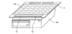
- FIG. It is a perspective view which shows schematic structure of the induction heating cooking appliance which concerns on Embodiment 5.
- FIG. (Constitution) 1 is an exploded perspective view showing an induction heating cooker in the cooking system according to Embodiment 1.
- an induction heating cooker 100 has a top plate 4 on which a heated object 5 such as a pan and a load such as a cooking device 200 are placed.
- FIG. 1 illustrates an example in which the object to be heated 5 is placed as a load.
- the top plate 4 includes a first heating port 1, a second heating port 2, and a third heating port 3 as heating ports for inductively heating the article to be heated 5, and corresponds to each heating port.
- the first heating means 11, the second heating means 12, and the third heating means 13 are provided, and the object to be heated 5 can be placed on the respective heating ports to perform induction heating. Is.
- the first heating means 11 and the second heating means 12 are provided side by side on the front side of the main body, and the third heating means 13 is provided at substantially the center on the back side of the main body.
- positioning of each heating port is not restricted to this.
- three heating ports may be arranged side by side in a substantially straight line.
- the top plate 4 is entirely made of a material that transmits infrared rays, such as heat-resistant tempered glass or crystallized glass, and is watertight through a rubber packing or a sealing material between the outer periphery of the top opening of the induction heating cooker 100. Fixed to state.
- the top plate 4 has a circular shape indicating a rough placement position of the pan corresponding to the heating range (heating port) of the first heating means 11, the second heating means 12, and the third heating means 13.
- the pan position indication is formed by applying paint or printing.
- an operation unit 40a, an operation unit 40b, and an operation unit 40c are provided as input devices for setting a water heating mode, a fried food mode, a cooking device cooking mode, and the like. Yes. Further, in the vicinity of the operation unit 40, as the notification unit 42, a display unit 41a, a display unit 41b, and a display unit 41c for displaying the operation state of the induction heating cooker 100, the input / operation content from the operation unit 40, and the like. Is provided.
- the operation units 40a to 40c and the display units 41a to 41c are not particularly limited, for example, when the operation units 40a and 41c are provided for each heating port, or when the operation unit 40 and the display unit 41 are provided collectively.
- the operation units 40a to 40c are configured by mechanical switches such as push switches and tact switches, touch switches for detecting input operations based on changes in electrode capacitance, and the like.
- the display units 41a to 41c are configured by, for example, an LCD (Liquid Crystal Device), an LED, or the like.
- LCD Liquid Crystal Device
- the display operation unit 43 is configured by, for example, a touch panel in which touch switches are arranged on the upper surface of the LCD.
- a first heating means 11, a second heating means 12, and a third heating means 13 are provided below the top plate 4 and inside the induction heating cooker 100.
- Each heating means is a coil. It consists of It should be noted that an electric heater (for example, a nichrome wire, a halogen heater, or a radiant heater) that heats at least one of the first heating means 11, the second heating means 12, and the third heating means 13 by, for example, radiation. You may comprise.
- the coil is configured by winding a conductive wire made of an arbitrary metal with an insulating film (for example, copper, aluminum, etc.).
- a high frequency magnetic field is generated from each coil by supplying a high frequency current to each coil by the drive circuit 50.
- the induction heating cooker 100 includes a drive circuit 50 for supplying high-frequency power to the coils of the first heating means 11, the second heating means 12, and the third heating means 13, and the drive circuit 50.
- a control unit 45 for controlling the operation of the whole cooking device is provided.
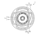
- FIG. 2 is a diagram showing first heating means of the induction heating cooker according to the first embodiment.
- the 1st heating means 11 is comprised by the inner periphery coil 11a arrange
- the outer periphery of the first heating unit 11 has a substantially circular shape corresponding to the first heating port 1.
- the inner peripheral coil 11a is composed of an inner peripheral inner coil 111a and an inner peripheral outer coil 112a that are arranged substantially concentrically.
- the inner circumference inner coil 111a and the inner circumference outer coil 112a have a circular planar shape, and a conductive wire made of any metal (for example, copper, aluminum, etc.) coated with an insulating film is wound in the circumferential direction. It is configured.
- the inner circumference inner coil 111 a and the inner circumference outer coil 112 a are connected in series and driven and controlled by one drive circuit 50. Note that the inner circumference inner coil 111a and the inner circumference outer coil 112a may be connected in parallel, or may be driven using independent drive circuits (inverter circuits).
- the outer peripheral coil 11b is composed of an outer peripheral left coil 111b and an outer peripheral right coil 112b.
- the outer peripheral coil 11c includes an outer peripheral upper coil 111c and an outer peripheral lower coil 112c.
- the outer peripheral left coil 111b and the outer peripheral right coil 112b are connected in series and are driven and controlled by one drive circuit 50.
- the outer periphery upper coil 111 c and the outer periphery lower coil 112 c are connected in series and are driven and controlled by one drive circuit 50.
- outer peripheral left coil 111b, the outer peripheral right coil 112b, the outer peripheral upper coil 111c, and the outer peripheral lower coil 112c are substantially aligned with the circular outer shape of the inner peripheral coil 11a. It is arranged around.
- the four outer coils have a substantially 1 ⁇ 4 arc shape (banana shape or pepper shape) planar shape, and conductive wires made of any metal (for example, copper, aluminum, etc.) coated with an insulating film are connected to the outer coil. It is configured by winding along a quarter arc shape.
- the outer peripheral coil is configured to extend substantially along the circular planar shape of the inner peripheral coil 11a in a 1 ⁇ 4 arc-shaped region adjacent to the inner peripheral coil 11a.
- the number of outer peripheral coils is not limited to four.
- the shape of the outer peripheral coil is not limited to this. For example, a configuration using a plurality of circular outer peripheral coils may be used.
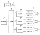
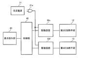
- FIG. 3 is a block diagram showing a drive circuit of the first heating means of the induction heating cooker according to the first embodiment.
- the first heating unit 11 is driven and controlled by driving circuits 50a, 50b, and 50c. That is, the inner circumference inner coil 111a and the inner circumference outer coil 112a constituting the inner circumference coil 11a are driven and controlled by the drive circuit 50a.
- the outer peripheral left coil 111b and the outer peripheral right coil 112b constituting the outer peripheral coil 11b are driven and controlled by the drive circuit 50b.
- the outer peripheral upper coil 111c and the outer peripheral lower coil 112c constituting the outer peripheral coil 11c are driven and controlled by the drive circuit 50c.
- AC power (commercial power) 21 is supplied from one AC power supply unit 21a to the drive circuits 50a, 50b, and 50c. That is, the supply of the AC power supply 21 to the induction heating cooker 100 is configured by only one AC power supply unit 21a.
- the AC power supply unit 21a is configured by a power plug connected to an outlet to which the AC power supply 21 is fed. Note that the configuration of the AC power supply unit 21a is not limited to this, and may be configured by, for example, a connection terminal connected to a power cable to which the AC power supply 21 is fed. For example, a round terminal or the like may be used as the connection terminal, and the end of the power cable may be arranged on the round terminal and fixed with screws.
- FIG. 3 shows a case where the drive circuits 50a, 50b, and 50c for driving the first heating unit 11 are supplied with the AC power supply 21 through one AC power supply unit 21a. Is not limited to this. All the drive circuits that drive the first heating means 11, the second heating means 12, and the third heating means 13 may be configured to be supplied with the AC power supply 21 through one AC power supply section 21a. good.
- the control unit 45 includes a microcomputer or a DSP (digital signal processor).
- the control unit 45 controls the drive circuits 50a, 50b, and 50c based on the operation content from the display operation unit 43 and the like. In addition, the control unit 45 performs display on the display operation unit 43 according to the operation state.
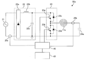
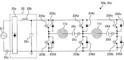
- FIG. 4 is a diagram illustrating a drive circuit of the induction heating cooker according to the first embodiment.
- the drive circuit 50 is provided for every heating means, the circuit structure may be the same and may be changed for every heating means.
- FIG. 4 shows a drive circuit 50a for driving the inner peripheral coil 11a.
- the drive circuit 50a includes a DC power supply circuit 22, an inverter circuit 23, and a resonance capacitor 24a.
- the input current detection means 25a is constituted by, for example, a current sensor, detects a current input from the AC power supply 21 to the DC power supply circuit 22, and outputs a voltage signal corresponding to the input current value to the control unit 45.
- the DC power supply circuit 22 includes a diode bridge 22a, a reactor 22b, and a smoothing capacitor 22c, converts an AC voltage input from the AC power supply 21 into a DC voltage, and outputs the DC voltage to the inverter circuit 23.
- the inverter circuit 23 is a so-called half-bridge type inverter in which IGBTs 23a and 23b as switching elements are connected in series to the output of the DC power supply circuit 22, and diodes 23c and 23d are parallel to the IGBTs 23a and 23b as flywheel diodes, respectively. It is connected to the.
- the IGBT 23 a and the IGBT 23 b are driven on and off by a drive signal output from the control unit 45.
- the control unit 45 turns off the IGBT 23b while turning on the IGBT 23a, turns on the IGBT 23b while turning off the IGBT 23a, and outputs a drive signal that turns on and off alternately.
- the inverter circuit 23 converts the DC power output from the DC power supply circuit 22 into a high-frequency AC power of about 20 kHz to 100 kHz, and supplies the power to the resonance circuit including the inner peripheral coil 11a and the resonance capacitor 24a. .
- the resonant capacitor 24a is connected in series to the inner peripheral coil 11a, and this resonant circuit has a resonant frequency corresponding to the inductance of the inner peripheral coil 11a, the capacity of the resonant capacitor 24a, and the like.
- the inductance of the inner peripheral coil 11a changes according to the characteristics of the metal load when the object to be heated 5 (metal load) is magnetically coupled, and the resonance frequency of the resonance circuit changes according to the change in the inductance.
- the IGBTs 23a and 23b which are switching elements, are composed of, for example, a silicon-based semiconductor, but may be configured using a wide band gap semiconductor such as silicon carbide or a gallium nitride-based material.
- the conduction loss of the switching element can be reduced, and since the heat radiation of the driving circuit is good even when the switching frequency (driving frequency) is high (high speed), the driving circuit Therefore, the size and cost of the driving circuit can be reduced.
- the coil current detection means 25b is connected to a resonance circuit composed of the inner peripheral coil 11a and the resonance capacitor 24a.
- the coil current detection means 25b is constituted by, for example, a current sensor, detects a current flowing through the inner peripheral coil 11a, and outputs a voltage signal corresponding to the coil current value to the control unit 45.
- the drive circuit 50a for driving the inner peripheral coil 11a has been described. However, the same configuration can be applied to the drive circuit 50b for driving the outer peripheral coil 11b and the drive circuit 50c for driving the outer peripheral coil 11c. . Note that the drive circuits 50 a, 50 b, and 50 c may be connected in parallel to the AC power supply 21.
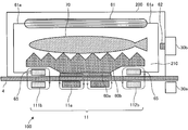
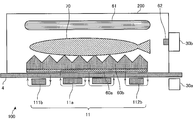
- FIG. 5 is a schematic diagram illustrating a configuration of the induction heating cooker and the cooking apparatus in the heating cooking system according to Embodiment 1.
- the cooking system includes an induction heating cooker 100 and a cooking device 200.
- the state by which the cooking apparatus 200 is mounted on the top plate 4 of the induction heating cooking appliance 100 is shown.
- the longitudinal cross-section which looked at the induction heating cooking appliance 100 and the cooking apparatus 200 from the front side is shown typically. Yes.
- the inner peripheral coil 11a and the outer peripheral coil 11b are arranged under the top plate 4 of the induction heating cooker 100.
- illustration of the outer peripheral upper coil 111c and the outer peripheral lower coil 112c constituting the outer peripheral coil 11c is omitted.
- the arrows shown around the inner peripheral coil 11a and the magnetic body 60a and the arrows shown around the outer peripheral left coil 111b, the outer peripheral right coil 112b, and the power receiving coil 65 indicate magnetic flux lines.
- the induction heating cooker 100 is provided with a primary transmission / reception unit 30a that communicates with the cooking device 200.
- the primary transmission / reception unit 30a is configured by a wireless communication interface conforming to an arbitrary communication standard such as Wi-Fi (registered trademark), Bluetooth (registered trademark), infrared communication, NFC (near field communication), and the like.
- the primary transmission / reception unit 30a performs two-way information communication with the secondary transmission / reception unit 30b of the cooking apparatus 200.
- the cooking apparatus 200 is an apparatus that cooks an object 70 such as a fish.
- Cooking device 200 is detachably supported by induction heating cooker 100.
- the cooking device 200 is placed on the top plate 4 of the induction heating cooker 100.
- a heating chamber 210 in which an object to be cooked 70 is accommodated is formed inside the casing.
- the cooking apparatus 200 includes a magnetic body 60a, a cooking table 60b, an upper surface heater 61, a temperature sensor 62, a power receiving coil 65, and a secondary transmission / reception unit 30b.
- the magnetic body 60 a is formed of a magnetic material such as iron, for example, and is disposed on the bottom surface of the cooking apparatus 200.
- the magnetic body 60a is induction-heated when it is placed in a high-frequency magnetic field generated by the inner peripheral coil 11a inside the induction heating cooker 100.
- the upper surface of the cooking table 60b has corrugated irregularities, and an object 70 such as fish is placed on the upper surface.
- the cooking table 60b is disposed in contact with the upper surface of the magnetic body 60a, for example, and the object to be cooked 70 is placed thereon.
- the cooking table 60b is made of, for example, a nonmagnetic metal such as aluminum, and is thermally coupled (joined) to the magnetic body 60a.
- the position of the cooking table 60b should just be arrange
- it may replace with the magnetic body 60a and the cooking stand 60b, and the structure which detachably accommodates in the heating chamber 210 the cooking pan, the pan, etc. which are the to-be-heated material to be heated by induction may be sufficient.
- both the magnetic body 60a and the cooking table 60b may be made of a magnetic material such as iron, or may be integrated with the magnetic material.
- the power receiving coil 65 is disposed on the bottom surface of the cooking apparatus 200.
- the power receiving coil 65 is configured by winding a conductive wire made of an arbitrary metal (for example, copper, aluminum, etc.) coated with an insulating film in the circumferential direction.
- the power receiving coil 65 receives power by electromagnetic induction or magnetic field resonance.
- the upper surface heater 61 is connected to the power receiving coil 65 by a wiring 61a.
- the upper surface heater 61 is configured by a heating element that generates heat (drives) by the power received by the power receiving coil 65.
- a sheathed heater that is a resistance heating element is used.
- the upper surface heater 61 is not limited to a specific configuration, and an arbitrary heating element such as a halogen heater or a far infrared heater can be used.
- the temperature sensor 62 is disposed in the heating chamber 210 and detects the temperature in the heating chamber 210.
- the temperature sensor 62 for example, a platinum resistance temperature detector, a thermistor, a thermocouple, or the like is used.
- a plurality of temperature sensors 62 may be provided as necessary. Further, the arrangement of the temperature sensor 62 is not limited to the wall surface of the heating chamber 210, and may be provided on the top surface, the bottom surface, or the cooking table 60b as necessary. Moreover, you may provide the non-contact-type temperature sensor 62 which detects the amount of infrared rays radiated
- the secondary transmission / reception unit 30b is configured by a wireless communication interface conforming to the communication standard of the primary transmission / reception unit 30a.
- the secondary transmission / reception unit 30b communicates information bidirectionally with the primary transmission / reception unit 30a of the induction heating cooker 100.
- the secondary transmission / reception unit 30b includes information on the temperature detected by the temperature sensor 62, information added to the cooking apparatus 200, information indicating the type of equipment of the cooking apparatus 200, information on equipment specifications of the cooking apparatus 200, and the like. It transmits to the primary transmission / reception part 30a.
- released may be sufficient.
- the outer shell of the cooking device 200 may be configured only by both side surfaces and the upper surface, and the front surface, the rear surface, and the bottom surface of the cooking device 200 may be open. In this case, a space surrounded by both side surfaces and the upper surface of the cooking apparatus 200 and the top plate 4 of the induction heating cooker 100 constitutes the heating chamber 210.
- the magnetic body 60 a and the power receiving coil 65 of the cooking apparatus 200 are arranged at positions corresponding to the coils arranged under the top plate 4 of the induction heating cooker 100.
- the positional relationship between the magnetic body 60 a and the power receiving coil 65 is arranged at a position corresponding to the positional relationship between the inner peripheral coil 11 a and the outer peripheral coils 11 b and 11 c of the first heating unit 11. An example will be described with reference to FIG.
- FIG. 6 is a top view schematically showing the configuration of the cooking device of the heating cooking system according to Embodiment 1.
- FIG. 6 in the cooking apparatus 200, for example, a magnetic body 60a and a power receiving coil 65 are disposed below a circular cooking table 60b.
- the magnetic body 60a is formed in a disk shape having an outer diameter substantially the same as the outer diameter of the inner peripheral coil 11a of the induction heating cooker 100. That is, in a state where the cooking apparatus 200 is placed on the top plate 4 of the induction heating cooker 100, the magnetic body 60a of the cooking apparatus 200 is disposed so as to overlap the inner peripheral coil 11a of the induction heating cooker 100 in the vertical direction.
- the magnetic body 60a has a shape that does not overlap with the outer peripheral coils 11b and 11c in the vertical direction.
- the four receiving coils 65 are provided around the magnetic body 60 a corresponding to the outer peripheral coils 11 b and 11 c of the induction heating cooker 100.
- the four power receiving coils 65 have substantially the same shape as the shape of the outer peripheral coils 11b and 11c of the induction heating cooker 100. That is, the four power receiving coils 65 have a substantially 1 ⁇ 4 arc shape (banana shape or pepper shape) planar shape, and a conductive wire made of any metal (for example, copper, aluminum, etc.) coated with an insulating film.
- the power receiving coil 65 is configured by being wound along a quarter arc shape.
- the power receiving coil 65 of the cooking apparatus 200 is preferably arranged so as not to overlap the inner peripheral coil 11a of the induction heating cooker 100 in the vertical direction but only to the outer peripheral coils 11b and 11c.
- the position of the power receiving coil 65 may be any position as long as it is disposed above at least a part of the outer peripheral coils 11b and 11c when the magnetic body 60a is disposed above the inner peripheral coil 11a. It is not limited to the position.
- the number of power receiving coils 65 is not limited to this, and may be at least one.
- the structure which provides the several receiving coil 65 with respect to one outer periphery coil may be sufficient.
- the magnetic body 60a and the inner peripheral coil 11a are arranged so as to overlap in the vertical direction.
- the magnetic body 60a is induction heated by the high frequency magnetic flux (high frequency magnetic field) generated from the inner peripheral coil 11a.
- the heat generated in the magnetic body 60a is thermally conducted to the thermally coupled cooking table 60b.
- the to-be-cooked object 70 placed on the cooking table 60b is cooked from below.
- the power receiving coil 65 and the outer peripheral coils 11b and 11c are arranged so as to overlap in the vertical direction.
- a high frequency current is supplied from the drive circuits 50b and 50c to the outer coils 11b and 11c
- a high frequency magnetic flux (high frequency magnetic field) is generated from the outer coils 11b and 11c.
- high frequency magnetic flux (high frequency magnetic field) is generated from the outer peripheral coils 11b and 11c
- electric power (electromotive force) due to electromagnetic induction is generated in the power receiving coil 65 of the cooking apparatus 200.
- the electric power generated in the power receiving coil 65 is supplied to the upper surface heater 61. Thereby, the upper surface heater 61 generates heat, and the cooking object 70 placed on the cooking table 60b is cooked from above by heat radiation.
- the inner peripheral coil 11a of the induction heating cooker 100 is used as an induction heating coil for induction heating the magnetic body 60a of the cooking apparatus 200.
- the outer peripheral coils 11 b and 11 c of the induction heating cooker 100 are used as power supply coils for performing non-contact power transmission to the upper surface heater 61 of the cooking apparatus 200. That is, the cooking by induction heating and the cooking by electric power received by non-contact power transmission are simultaneously performed on one object 70 to be cooked.
- the high-frequency current supplied from the drive circuit 50a to the inner peripheral coil 11a corresponds to the “first high-frequency current” in the present invention.
- the high frequency magnetic flux (high frequency magnetic field) generated from the inner peripheral coil 11a corresponds to the “first high frequency magnetic field” in the present invention.
- the high-frequency current supplied from the drive circuits 50b and 50c to the outer peripheral coils 11b and 11c corresponds to the “second high-frequency current” in the present invention.
- the high-frequency magnetic flux (high-frequency magnetic field) generated from the outer peripheral coils 11b and 11c corresponds to the “second high-frequency magnetic field” in the present invention.
- ferrite as a magnetic material on the lower surfaces of the inner peripheral coil 11 a and the outer peripheral coils 11 b and 11 c of the induction heating cooker 100. Further, it is desirable to similarly provide ferrite on the upper surface of the power receiving coil 65 of the cooking apparatus 200.
- the outer peripheral coils 11b and 11c are used as power feeding coils, the high frequency magnetic flux is easily interlinked by providing ferrite, and the leakage magnetic flux is reduced. Thereby, the high frequency power can be more effectively supplied to the power receiving coil 65, the power conversion efficiency is high, and the loss can be reduced.
- the high frequency magnetic flux from the inner peripheral coil 11a and the high frequency magnetic flux from the outer peripheral coils 11b and 11c can be reduced. Interference is reduced. For this reason, the loss in non-contact electric power transmission at the time of using the outer periphery coils 11b and 11c as a feed coil can reduce, and can improve electric power transmission efficiency more.
- the inner coil 11a corresponds to the “first coil” of the present invention.
- the inverter circuit 23 of the drive circuit 50a corresponds to the “first inverter circuit” of the present invention, and may include the DC power supply circuit 22 of the drive circuit 50a.
- the outer coils 11b and 11c correspond to the “second coil” of the present invention.
- the inverter circuit 23 of the drive circuits 50b and 50c corresponds to the “second inverter circuit” of the present invention, and may include the DC power supply circuit 22 of the drive circuits 50b and 50c.
- the magnetic body 60a corresponds to the “object to be heated” of the present invention.
- the upper surface heater 61 corresponds to “cooking means” of the present invention.
- the control unit 45 corresponds to a “control device” of the present invention.
- the user places an object to be cooked 70 such as a fish on the cooking table 60b inside the cooking apparatus 200.
- the user places the cooking device 200 on the heating port of the top plate 4 of the induction heating cooker 100.
- the following description demonstrates the case where the cooking apparatus 200 is mounted in the 1st heating port 1 (1st heating means 11).
- the user instructs to start cooking (throwing in thermal power) at the display operation unit 43.
- the display operation unit 43 incorporates a dedicated mode (menu) for operating the cooking apparatus 200, and can be easily cooked by selecting the dedicated mode.
- the control unit 45 of the induction heating cooker 100 controls the drive circuit 50a according to the heating power to be induction-heated, and performs a heating operation of supplying high-frequency power to the inner peripheral coil 11a.
- positioned at the lower surface of the cooking table 60b of the cooking apparatus 200 is induction-heated.
- the heat generated by the magnetic body 60a due to induction heating is transferred to the non-magnetic cooking table 60b, and the cooking object 70 placed on the upper surface of the cooking table 60b is directly heated from the lower surface.
- the control unit 45 of the induction heating cooker 100 controls the drive circuits 50b and 50c in accordance with the power transmitted to the power receiving coil 65, respectively, and supplies high-frequency power to the outer peripheral coils 11b and 11c. I do.
- the high frequency electric power supplied from the outer peripheral coils 11b and 11c is received by the power receiving coil 65 arranged on the lower surface of the cooking apparatus 200.
- the received power is supplied to the upper surface heater 61, and the upper surface heater 61 generates heat.
- the upper surface heater 61 heats the to-be-cooked object 70 placed on the upper surface of the cooking table 60b from the upper surface by heat radiation.
- the rated power of the cooking apparatus 200 is 1500 W, for example.
- the control unit 45 controls the driving of the drive circuits 50b and 50c so that the power received by the power receiving coil 65 is equal to or lower than the rated power (1500 W).
- the control unit 45 may control the drive circuits 50 a, 50 b, and 50 c according to the temperature detected by the temperature sensor 62.
- the control unit 45 acquires information about the temperature detected by the temperature sensor 62 of the cooking apparatus 200 via the primary transmission / reception unit 30a.
- the control part 45 is set so that the temperature in the heating chamber 210 of the cooking device 200 may become a desired temperature according to the preset temperature set by the display operation part 43 or the temperature preset by the cooking menu.
- the drive of the drive circuits 50a, 50b, 50c is controlled to control the heat generation amount (thermal power) of the magnetic body 60a and the upper surface heater 61.
- a plurality of temperature sensors 62 may be provided in the vertical direction in the heating chamber 210.
- the control unit 45 controls the heating power (power supplied to the inner peripheral coil 11a) for induction heating the magnetic body 60a according to the temperature detected by the temperature sensor 62 provided on the lower side. Further, the control unit 45 controls the heating power of the upper surface heater 61 (power supplied to the outer peripheral coils 11b and 11c) according to the temperature detected by the temperature sensor 62 provided on the upper side.
- the induction heating cooker 100 is provided separately from the drive circuit 50a for supplying the high frequency current to the inner peripheral coil 11a and the drive circuit 50a, and the high frequency is applied to the outer peripheral coils 11b and 11c.
- Drive circuits 50b and 50c for supplying current are provided.
- the cooking apparatus 200 includes a power receiving coil 65 that receives power from the outer peripheral coils 11b and 11c, and a top heater 61 that generates heat by the power received by the power receiving coil 65. For this reason, cooking by induction heating and cooking by non-contact power transmission can be performed simultaneously. Moreover, cooking by induction heating and cooking by non-contact power transmission can be individually controlled. Therefore, an induction heating cooker that can be deliciously cooked in a short time can be obtained.
- the temperature sensor 62 which detects the temperature in the heating chamber 210 of the cooking apparatus 200, and the secondary transmission / reception part 30b which transmits the information of the detected temperature are provided.
- the control unit 45 acquires information on the temperature detected by the temperature sensor 62 via the primary transmission / reception unit 30a. And the control part 45 controls the drive of the drive circuit 50a and the drive circuits 50b and 50c according to the temperature which the temperature sensor 62 detected, respectively. For this reason, the control part 45 can control separately the heating by induction heating and the heating by non-contact electric power transmission according to the temperature detected by the temperature sensor 62. Therefore, the internal temperature of the cooking apparatus 200 and the temperature of the cooking dish can be finely controlled, and cooking can be easily performed with few failures.
- an AC power supply unit 21a connected to the AC power supply 21 is provided, and the plurality of drive circuits are supplied with the AC power supply 21 through one AC power supply unit 21a. For this reason, the workability at the time of installing the induction heating cooking appliance 100 can be improved.
- the outer periphery coils 11b and 11c demonstrated four coils
- the number of coils is not this limitation.
- the four coils are driven by the two drive circuits 50
- the combination of the coil and the drive circuit (inverter circuit) is not particularly limited, and the same effect can be obtained by driving the four coils individually. Play.
- the to-be-heated material 5 such as a pan is mounted, and an inner peripheral coil is mounted.
- 11a and outer peripheral coils 11b and 11c as induction heating coils, the entire surface of the heating port can also be induction heated.
- induction heating the entire surface of the heating port it is possible to increase the area of the induction heating unit, and it is possible to obtain an induction heating cooker that can realize sufficient heating even when a large pan is used.
- the input power of the inner peripheral coil 11a and the outer peripheral coils 11b and 11c can be individually controlled.
- the induction heating part can be switched by sequentially switching energization to the inner peripheral coil 11a and the outer peripheral coils 11b and 11c.
- convection stew can be realized at the time of cooking boiled food, and an induction heating cooker capable of cooking deliciously can be obtained.
- the heating cooking system provided with the induction heating cooking appliance 100 and the cooking apparatus 200 was demonstrated, this invention is not restricted to this, All the components of the cooking apparatus 200 are induction-heated.
- the cooking device 100 may be provided, and the cooking device 200 may be omitted.
- the induction heating cooker 100 may include a part of the configuration of the cooking apparatus 200.
- FIG. 7 is a schematic diagram illustrating a modified example of the cooking apparatus in the heat cooking system according to the first embodiment.
- the cooking device 200 shown in FIG. 7 includes a stirring device 80 as cooking means that is driven by the power received by the power receiving coil 65.
- the stirring device 80 includes a motor 81, a shaft 82, and a blade portion 83.
- the motor 81 is provided, for example, in the upper part of the casing of the cooking apparatus 200 and is driven to rotate by the power received by the power receiving coil 65.
- the shaft 82 has a rotational axis arranged in the vertical direction, and one end is connected to the motor 81 to transmit the driving force of the motor 81.
- the blade portion 83 is attached to the shaft 82 and agitates the food 70 by the rotational driving of the shaft 82.
- the bottom surface of the casing constituting the outer shell is opened.
- the bottom surface of the casing of the cooking apparatus 200 is open at least in a range overlapping with the inner peripheral coil 11a of the induction heating cooker 100 in the vertical direction.
- a heated object 5 such as a pan or a frying pan into which an object 70 to be cooked such as stew or fried food is placed is placed on the top plate 4 so as to overlap the inner peripheral coil 11a in the vertical direction. Then, the blade
- FIG. When a high frequency current is supplied from the drive circuit 50a to the inner peripheral coil 11a, the object to be heated 5 is induction heated by the high frequency magnetic flux (high frequency magnetic field) generated from the inner peripheral coil 11a. Thereby, the to-be-cooked item 70 in the to-be-heated item 5 is cooked from below.
- a high frequency magnetic flux (high frequency magnetic field) is generated from the outer coils 11b and 11c.
- high frequency magnetic flux (high frequency magnetic field) is generated from the outer peripheral coils 11b and 11c, electric power (electromotive force) due to electromagnetic induction is generated in the power receiving coil 65 of the cooking apparatus 200.
- the power generated in the power receiving coil 65 is supplied to the stirring device 80, the motor 81 is driven, and the blade portion 83 is rotationally driven via the shaft 82. Thereby, the to-be-cooked object 70 in the to-be-heated object 5 is stirred and cooked.
- cooking by induction heating and stirring cooking by non-contact power transmission can be performed simultaneously. Moreover, heating cooking by induction heating and stirring cooking by non-contact power transmission can be individually controlled. Therefore, an induction heating cooker that can be deliciously cooked in a short time can be obtained.
- the power receiving coil 65 may be provided corresponding to only a part of the outer peripheral coil 11b and the outer peripheral coil 11c.
- the receiving coil 65 corresponding to at least 1 coil among the outer periphery left coil 111b, the outer periphery right coil 112b, the outer periphery upper coil 111c, and the outer periphery lower coil 112c.
- a coil other than the coil corresponding to the power receiving coil 65 may be operated as a coil for induction heating the article to be heated 5.
- a position display indicating the mounting position of the object to be heated 5 and a position display indicating the mounting position of the power receiving coil 65 are applied or printed. It may be formed by such as.
- a cooking means is not limited to this.
- a cooling device having a Peltier element may be provided as cooking means driven by the power received by the power receiving coil 65.
- heating cooking by induction heating and cooling cooking by non-contact power transmission can be performed simultaneously or sequentially. Therefore, the wide cooking which can adjust the temperature range given to the to-be-heated material 5 and the to-be-cooked object 70 in a wide range can be performed.
- a cooking means that is driven by the power received by the power receiving coil 65 for example, a device that flips the cooking object 70 on the heating object 5 up and down may be provided.
- the upper and lower surfaces of the object 70 can be brought into contact with the object 5 to be heated. Therefore, for example, burnt eyes generated by the contact between the object to be heated 5 and the object to be cooked 70 can be applied to both surfaces of the object to be cooked 70.
- FIG. 8 is a diagram illustrating another drive circuit of the induction heating cooker according to the first embodiment.
- the drive circuit 50a shown in FIG. 8 is configured by a so-called full-bridge inverter in which IGBTs 232a and 232b as switching elements and diodes 232c and 232d as flywheel diodes are additionally connected to the inverter circuit 23 of FIG. Has been.
- Other configurations are the same as those in FIG. 4, and the same portions are denoted by the same reference numerals.
- the control unit 45 outputs a drive signal for driving each switching element (IGBT 231a, 231b, 232a, 232b) of the inverter circuit 23, and the electric power input to the inner peripheral coil 11a is a heating operation similarly to the above-described operation.
- the power is controlled so as to be the power set in. Even in such a configuration, the same effect can be obtained.
- FIG. 9 is a diagram showing another drive circuit of the induction heating cooker according to the first embodiment.
- the driving circuit 50b for driving the outer peripheral coil 11b and the driving circuit 50c for driving the outer peripheral coil 11c are configured by a full bridge type inverter circuit, and one of the arms configuring the full bridge. Is a common arm.
- the drive circuits 50b and 50c are composed of full-bridge inverters as in FIG.
- the arm composed of two IBGTs 234a and 234b is used as a common arm, the outer coil 11b (feed coil) is driven and controlled by the IGBT 233a and 233b and the common arm, and the outer coil 11c (feed coil) is driven by the IGBT 235a and 235b and the common arm. It is the structure to control. Even in such a configuration, the outer peripheral coil 11b and the outer peripheral coil 11c can be driven and controlled, and the same effects as those described above can be obtained.
- FIG. 10 is a diagram showing another first heating unit of the induction heating cooker according to the first embodiment.
- the first heating means 11 shown in FIG. 10 includes an inner peripheral coil 11a disposed at the center of the heating port, and an outer peripheral coil 11d disposed substantially concentrically with the inner peripheral coil 11a.
- the inner peripheral coil 11a includes an inner peripheral inner coil 111a and an inner peripheral outer coil 112a, which are connected in series, and are driven and controlled by the drive circuit 50a.
- the outer peripheral coil 11d has an outer peripheral inner coil 111d and an outer peripheral outer coil 112d that are formed concentrically with the inner peripheral coil 11a.
- the outer periphery inner coil 111d and the outer periphery outer coil 112d are respectively connected in series and driven and controlled by the drive circuit 50d.
- the configuration of the drive circuit 50d is the same as that of the drive circuit 50a described above.
- the receiving coil 65 of the cooking apparatus 200 in this configuration example is formed concentrically with the center of the magnetic body 60a corresponding to the shape of the outer peripheral coil 11d.
- the inner peripheral coil 11a of the induction heating cooker 100 is used as an induction heating coil for heating the magnetic body 60a of the cooking apparatus 200.
- the outer periphery coil 11d can acquire the effect similar to the effect mentioned above by being used as a feeding coil for performing non-contact electric power transmission to the upper surface heater 61 of the cooking apparatus 200.
- the coil configuration is simpler than the above-described coil configuration in FIG. 2, an equivalent effect can be obtained with an inexpensive configuration.
- FIG. FIG. 11 and FIG. 12 are block diagrams showing the configuration of the cooking device of the heat cooking system according to the second embodiment.
- FIG. 13 is a top view schematically showing the configuration of the cooking device of the heating cooking system according to the second embodiment.
- FIG. 11 FIG. 12, the state by which the cooking apparatus 200 is mounted on the top plate 4 of the induction heating cooking appliance 100 is shown.
- FIG. 11 the longitudinal cross section which looked at the induction heating cooking appliance 100 and the cooking apparatus 200 from the front side is shown typically.
- FIG. 12 the longitudinal cross section which looked at the induction heating cooking appliance 100 and the cooking apparatus 200 from the side surface side is shown typically.
- the difference from the first embodiment will be mainly described.
- the magnetic body 60a and the cooking table 60b in the second embodiment are formed in a rectangular shape in a top view.
- the magnetic body 60a and the cooking table 60b are formed such that the length of the long side is longer than the width of the heating port, for example, and the length of the short side is substantially equal to the width (outer diameter) of the inner peripheral coil 11a. It is formed in length.
- the magnetic body 60a and the cooking table 60b are placed on the top 4 so that the long sides of the magnetic body 60a and the cooking table 60b face in the left-right direction, as shown in FIGS.
- the edge part of the outer periphery left coil 111b of the induction heating cooking appliance 100 is arrange
- variety of the front-back direction of the magnetic body 60a and the cooking stand 60b becomes substantially equivalent to the width
- the power receiving coil 65 in the present second embodiment is arranged so as to sandwich the long sides on both sides of the magnetic body 60a and the cooking table 60b, for example.
- Two power receiving coils 65 are provided corresponding to the outer periphery upper coil 111 c and the outer periphery lower coil 112 c of the induction heating cooker 100.
- the two power receiving coils 65 have a substantially 1 ⁇ 4 arc-shaped (banana-shaped or pepper-shaped) planar shape, and receive a conductive wire made of any metal (for example, copper, aluminum, etc.) coated with an insulating film. It is comprised by winding along the 1/4 circular arc shape of 65.
- FIG. 14 is a diagram showing first heating means of the induction heating cooker according to the second embodiment.
- the configuration of the first heating unit 11 is the same as that of the first embodiment, but the drive control in the control unit 45 is different. That is, the control unit 45 controls the drive circuit 50a for driving the inner peripheral coil 11a and the drive circuit 50b for driving the outer peripheral coil 11b (the outer peripheral left coil 111b and the outer peripheral right coil 112b) according to the heating power to be induction-heated. Then, a heating operation for supplying high-frequency power is performed. Thereby, the magnetic body 60a arrange
- the control unit 45 controls the drive circuit 50c according to the power transmitted to the power receiving coil 65, and supplies non-contact power transmission for supplying high frequency power to the outer coil 11c (the outer coil 111c and the lower coil 112c). Perform the action.
- the high frequency power supplied from the outer peripheral coil 11 c is received by the power receiving coil 65 disposed on the lower surface of the cooking apparatus 200.
- the received power is supplied to the upper surface heater 61, and the upper surface heater 61 generates heat.
- the upper surface heater 61 heats the to-be-cooked object 70 placed on the upper surface of the cooking table 60b from the upper surface by heat radiation.
- the widths of the magnetic body 60a and the cooking table 60b are increased, and the magnetic body 60a is induction-heated by the inner peripheral coil 11a and the outer peripheral coil 11b. To do. For this reason, by increasing the area of the lower surface heating by induction heating, it is possible to generate an appropriate burnish from the lower surface. For example, even if the cooking object 70 has a long shape such as fish, the cooking object 70 can be placed on the cooking table 60b, and the cooking object 70 such as fish is cooked deliciously by heating the bottom surface. Is possible.
- the feeding coils for supplying power to the upper surface heater 61 of the cooking apparatus 200 are the outer periphery upper coil 111c and the outer periphery lower coil 112c. Compared with FIG. Less. For this reason, the electric power to the outer periphery upper coil 111c and the outer periphery lower coil 112c is increased so that the electric power supplied to the upper surface heater 61 may not fall. Thereby, the cooking apparatus 200 which can cook deliciously in a short time can be obtained, without impairing cooking time.
- Embodiment 3 a configuration in which cooking by induction heating and cooking by non-contact power transmission is performed using a plurality of heating means will be described.
- the same parts as those in the first embodiment are denoted by the same reference numerals, and the difference from the first embodiment will be mainly described.
- FIG. 15 is a block diagram illustrating a second heating unit and a driving circuit for the third heating unit of the induction heating cooker according to the third embodiment.
- the second heating means 12 is driven and controlled by a drive circuit 50e.
- the third heating unit 13 is driven and controlled by the driving circuit 50f. That is, a coil (not shown) constituting the second heating means 12 is driven and controlled by the drive circuit 50e, and a coil (not shown) constituting the third heating means 13 is driven and controlled by the drive circuit 50f. Is done.
- the second heating means 12 and the third heating means 13 may be configured to include one coil, and, similarly to the first embodiment, an inner peripheral coil and an outer peripheral coil disposed around the inner peripheral coil.
- positioned the several coil concentrically may be sufficient. Further, in the case of a configuration including a plurality of coils, a configuration including a plurality of drive circuits for one heating means may be used.
- AC power (commercial power) 21 is supplied from one AC power supply unit 21a to the drive circuits 50e and 50f. That is, the supply of the AC power supply 21 to the induction heating cooker 100 is configured by only one AC power supply unit 21a.
- the AC power supply unit 21a is configured by a power plug connected to an outlet to which the AC power supply 21 is fed. Note that the configuration of the AC power supply unit 21a is not limited to this, and may be configured by, for example, a connection terminal connected to a power cable to which the AC power supply 21 is fed. For example, a round terminal or the like may be used as the connection terminal, and the end of the power cable may be arranged on the round terminal and fixed with screws.
- the drive circuit 50e for driving the second heating unit 12 and the drive circuit 50f for driving the third heating unit 13 are supplied with the AC power supply 21 through one AC power supply unit 21a.
- the present invention is not limited to this. All the drive circuits that drive the first heating means 11, the second heating means 12, and the third heating means 13 may be configured to be supplied with the AC power supply 21 through one AC power supply section 21a. good.
- FIG. 16 is a schematic diagram illustrating a configuration of an induction heating cooker and a cooking apparatus in the heating cooking system according to the third embodiment.
- the cooking system includes an induction heating cooker 100 and a cooking device 200.
- the state by which the cooking apparatus 200 is mounted on the top plate 4 of the induction heating cooking appliance 100 is shown.
- the to-be-heated material 5 is mounted above the 2nd heating means 12, and the cooking apparatus 200 is mounted above the 2nd heating means 12 and the 3rd heating means 13.
- 1 schematically shows a longitudinal section of the induction heating cooker 100 and the cooking apparatus 200 as viewed from the front side.
- positioning position of the to-be-heated material 5 and the cooking apparatus 200 is not limited to this, It can arrange
- the cooking apparatus 200 includes an upper surface heater 61, a power receiving coil 65, and a support unit 220.
- the power receiving coil 65 is disposed at the bottom of the cooking apparatus 200.
- the power receiving coil 65 is configured by winding a conductive wire made of an arbitrary metal (for example, copper, aluminum, etc.) coated with an insulating film in the circumferential direction.
- the power receiving coil 65 receives power by electromagnetic induction or magnetic field resonance. In the example shown in FIG. 16, the power receiving coil 65 receives power by a high frequency magnetic field generated by a coil constituting the third heating unit 13.
- the upper surface heater 61 is connected to the power receiving coil 65 by wiring (not shown).
- the upper surface heater 61 is configured by a heating element that generates heat (drives) by the power received by the power receiving coil 65.
- a sheathed heater that is a resistance heating element is used.
- the upper surface heater 61 is not limited to a specific configuration, and an arbitrary heating element such as a halogen heater or a far infrared heater can be used. Further, the upper surface heater 61 is supported above the object to be heated 5 by the support means 220.
- the support means 220 is formed by, for example, a casing that constitutes the outline of the cooking apparatus 200.
- the support means 220 is formed in an L-shaped cross section that extends upward from the bottom surface that houses the power receiving coil 65 and then extends in the horizontal direction. That is, when the power receiving coil 65 is disposed above the third heating means 13 (third heating port 3), the support means 220 causes the upper surface heater 61 to move above the second heating means 12 (second heating).
- the upper surface heater 61 is supported so as to be positioned above the mouth 2) and the article 5 to be heated.
- the distance between the top plate 4 and the upper surface heater 61 when the cooking apparatus 200 is arranged on the top plate 4 is set to be higher than the height of a pan, a frying pan, or the like assumed as the article to be heated 5.
- the support means 220 may be configured to drive the upper surface heater 61 in the vertical direction.
- the user places an object to be heated 5 such as a frying pan in the second heating port 2 of the top plate 4.
- the user places the power receiving coil 65 (bottom part of the casing) of the cooking device 200 on the third heating port 3 of the top plate 4.
- the display operation unit 43 instructs the second heating port 2 to start cooking (fire power input) by the user.
- An instruction to start cooking (start feeding) for the third heating port 3 is given by the display operation unit 43.
- the display operation unit 43 incorporates a dedicated mode (menu) for operating the cooking apparatus 200, and can be easily cooked by selecting the dedicated mode.
- the control unit 45 of the induction heating cooker 100 controls the drive circuit 50e in accordance with the heating power to be induction-heated to supply high-frequency power to the coil of the second heating means 12. Perform the action. Thereby, the to-be-heated object 5 mounted in the 2nd heating port 2 is induction-heated. And the to-be-cooked object 70 placed in the to-be-heated object 5 is directly heated from the lower surface.
- the control unit 45 of the induction heating cooker 100 controls the drive circuit 50f according to the power transmitted to the power receiving coil 65 to supply high-frequency power to the coil of the third heating unit 13. I do.
- the high frequency electric power supplied from the coil of the 3rd heating means 13 is received by the receiving coil 65 arrange
- the received power is supplied to the upper surface heater 61, and the upper surface heater 61 generates heat.
- the rated power of the second heating means 12 is, for example, 3000 W.
- the control unit 45 controls the drive of the drive circuit 50e so that the electric power supplied to the coil constituting the second heating unit 12 is equal to or lower than the rated electric power (3000 W).
- the rated power of the cooking apparatus 200 is 1500 W, for example.
- the control unit 45 controls the drive of the drive circuit 50f so that the power received by the power receiving coil 65 is equal to or lower than the rated power (1500 W). That is, it is possible to make the total power of the power for induction heating the object to be heated 5 and the power transmitted to the power receiving coil 65 larger than the rated power of one heating means.
- the cooking apparatus 200 was mounted in the 3rd heating port 3 and non-contact electric power transmission was performed to the receiving coil 65 was demonstrated, not only this but the cooking apparatus 200 is demonstrated.
- the object 5 to be heated may be disposed in the third heating port 3 and the heating operation by the third heating means 13 may be performed.
- the arbitrary heating port among the 1st heating port 1, the 2nd heating port 2, and the 3rd heating port 3 as a heating port for exclusive use which performs non-contact electric power transmission. That is, the display of the top plate 4 that constitutes a dedicated heating port that performs non-contact power transmission functions as a position display that indicates the mounting position of the power receiving coil 65.
- the display of the heating port which places the article to be heated 5 and performs the heating operation corresponds to the “first position display” of the present invention
- the position display indicating the mounting position of the power receiving coil 65 is the display of the present invention. This corresponds to “second position display”.
- the induction heating cooker 100 is provided separately from the drive circuit 50e and the drive circuit 50e that supply the high-frequency current to the coil of the second heating means 12, and the third And a drive circuit 50f for supplying a high-frequency current to the coil of the heating means 13.
- the cooking apparatus 200 includes a power receiving coil 65 that receives power from the coil of the third heating unit 13 and a top heater 61 that generates heat by the power received by the power receiving coil 65. For this reason, cooking by induction heating and cooking by non-contact power transmission can be performed simultaneously. Moreover, cooking by induction heating and cooking by non-contact power transmission can be individually controlled. Therefore, an induction heating cooker that can be deliciously cooked in a short time can be obtained.
- the top surface heating by the top surface heater 61 and the induction heating by the heat from the article to be heated 5 can be individually controlled by the individually provided drive circuit 50e and drive circuit 50f, cooking is delicious in a short time. It is possible to obtain an induction heating cooker that can be used.
- an AC power supply unit 21a connected to the AC power supply 21 is provided, and the plurality of drive circuits are supplied with the AC power supply 21 through one AC power supply unit 21a. For this reason, the workability at the time of installing the induction heating cooking appliance 100 can be improved.
- the heating means that performs induction heating and the heating means that performs non-contact power transmission are different, so that the power for induction heating the object to be heated 5 and the power receiving coil 65 are transmitted. It becomes possible to make the total power with the power to be larger than the rated power of one heating means. Moreover, since all the coils which comprise one heating means are operate
- FIG. 17 is a schematic diagram illustrating a modified example of the cooking apparatus in the heat cooking system according to the third embodiment.
- a cooking device 200 shown in FIG. 17 includes a stirring device 80 as cooking means that is driven by the power received by the power receiving coil 65.
- the structure of the stirring apparatus 80 is the same as that of the modification 1 in the said Embodiment 1, the same code
- the stirring apparatus 200 shown in FIG. 17 for example, when a heated object 5 such as a pan or a frying pan into which an object 70 to be cooked such as stew or fried food is placed is placed on the second heating port 2, the stirring apparatus. 80 blade parts 83 are arranged in the article to be heated 5.
- the object to be heated 5 is induction heated by the high frequency magnetic flux (high frequency magnetic field) generated from the coil. Thereby, the to-be-cooked item 70 in the to-be-heated item 5 is cooked from below.
- cooking by induction heating and stirring cooking by non-contact power transmission can be performed simultaneously. Moreover, heating cooking by induction heating and stirring cooking by non-contact power transmission can be individually controlled. Therefore, an induction heating cooker that can be deliciously cooked in a short time can be obtained.
- a cooking means is not limited to this.
- a cooling device having a Peltier element may be provided as cooking means driven by the power received by the power receiving coil 65.
- heating cooking by induction heating and cooling cooking by non-contact power transmission can be performed simultaneously or sequentially. Therefore, the wide cooking which can adjust the temperature range given to the to-be-heated material 5 and the to-be-cooked object 70 in a wide range can be performed.
- a device that inverts the object 70 to be cooked on the object to be heated 5 may be provided.
- the both surfaces of the up-down direction of the to-be-cooked object 70 can be made to contact the to-be-heated object 5. Therefore, for example, burnt eyes generated by the contact between the object to be heated 5 and the object to be cooked 70 can be applied to both surfaces of the object to be cooked 70.
- Embodiment 4 it is detected whether any of the magnetic body 60a or the power receiving coil 65 of the cooking apparatus 200 is placed above the coil of the induction heating cooker 100, and according to the detection result. The operation for switching between the heating operation and the non-contact power transmission operation will be described.
- the configuration of induction heating cooker 100 in the fourth embodiment is the same as that of the first embodiment, and the configuration of cooking apparatus 200 is the same as that of any of the first to third embodiments.
- control unit 45 When the user places the cooking device 200 on the heating port and instructs the display operation unit 43 to start heating (heating power input), the control unit 45 (load determination unit) performs load determination processing. Note that the control unit 45 in the fourth embodiment includes the function of the “load determination unit” of the present invention.
- FIG. 18 is a load discrimination characteristic diagram based on the relationship between the coil current and the input current in the induction heating cooker according to the fourth embodiment.
- the control unit 45 stores therein in advance a load determination table in which the relationship between the coil current and the input current shown in FIG. 18 is tabulated. By storing the load determination table therein, the load determination unit can be configured with an inexpensive configuration.
- the control unit 45 drives the inverter circuit 23 with a specific drive signal for load determination for each of the drive circuits, and detects the input current from the output signal of the input current detection means 25a. At the same time, the control unit 45 detects the coil current from the output signal of the coil current detection means 25b. The control unit 45 determines the material of the load placed above the coil from the detected coil current and input current and a load determination table representing the relationship of FIG.
- the control unit 45 determines that the magnetic body 60a of the cooking apparatus 200 or the object to be heated 5 is placed above the coil.
- the load determination result is a material other than the magnetic material, it is determined that the power receiving coil 65 is placed above the coil. If the load determination result is no load, it is determined that none of the magnetic body 60a, the object to be heated 5, and the power receiving coil 65 is placed.
- control unit 45 controls the drive circuit 50 that drives the coil that is determined to have the magnetic body 60a or the object to be heated 5 mounted thereon among the coils that constitute the heating means, and performs induction.
- a heating operation for supplying high-frequency power corresponding to the heating power to be heated is performed.
- the control unit 45 controls the drive circuit 50 that drives the coil that is determined to have the power receiving coil 65 mounted thereon among the coils that constitute the heating means, and converts the power to be transmitted to the power receiving coil 65.
- a contactless power transmission operation for supplying the corresponding high frequency power is performed. Note that the control unit 45 stops the operation of the drive circuit 50 that drives the coil determined to be unloaded. Subsequent operations are the same as those in the first embodiment.
- the fourth embodiment it is detected whether any of the magnetic body 60a, the object to be heated 5, and the power receiving coil 65 is placed above the coil, and according to the detection result.
- a heating operation or non-contact power transmission operation is performed by the coil. For this reason, the operation
- the load determination is performed based on the correlation between the input current and the coil current.
- the present invention is not limited to this, and any load determination process can be used.
- the frequency of the high-frequency current supplied to the coil may be continuously changed, and the load determination may be performed based on the change characteristic of the input current at that time.
- FIG. 19 is a perspective view showing a schematic configuration of the induction heating cooker according to the fifth embodiment.
- a plurality of relatively small coils 120 are almost uniformly distributed below the top plate 4.
- the plurality of coils 120 are individually driven by the drive circuit 50, or several adjacent coils among the plurality of coils 120 are driven as one coil group.
- the configuration of the drive circuit 50 that drives the coil 120 is the same as the configuration of the drive circuit 50a of the first embodiment, for example.
- control unit 45 performs load determination of the load placed above each of the plurality of coils 120.
- the load determination process is the same as that in the fourth embodiment.
- FIG. 5 it is good also as a structure which does not provide the display of a heating port on the top plate 4.
- FIG. The number of coils 120 may be an arbitrary number.
- the layout of the coil 120 is not limited to this, and the coil 120 may be arranged in a honeycomb shape, or the large coil 120 and the small coil 120 may be mixed.
- the control unit 45 performs load determination processing. Do.
- the controller 45 performs a load determination process for determining the material of the load placed above for each of the plurality of coils 120 by the same operation as in the fourth embodiment.
- the controller 45 determines that the magnetic body 60a of the cooking apparatus 200 or the object to be heated 5 is placed above the coil 120.
- the load determination result is a material other than the magnetic material, it is determined that the power receiving coil 65 is placed above the coil 120. If the load determination result is no load, it is determined that none of the magnetic body 60a, the object to be heated 5, and the power receiving coil 65 is placed.
- the control part 45 controls the drive circuit 50 which drives the coil 120 determined that the magnetic body 60a or the object to be heated 5 is placed above the plurality of coils 120, and causes induction heating.
- a heating operation is performed to supply high-frequency power according to the thermal power.
- the control unit 45 controls the drive circuit 50 that drives the coil 120 that is determined to have the power receiving coil 65 mounted thereon among the plurality of coils 120, and responds to the power transmitted to the power receiving coil 65.
- a contactless power transmission operation for supplying high frequency power is performed.
- the controller 45 stops the operation of the drive circuit 50 that drives the coil 120 that has been determined to be unloaded. Subsequent operations are the same as those in the first embodiment.
- the fifth embodiment includes the plurality of coils 120 arranged almost uniformly below the top plate 4. Then, the control unit 45 detects whether or not any one of the magnetic body 60a, the object to be heated 5, and the power receiving coil 65 is placed above each of the plurality of coils 120. And the control part 45 performs the heating operation
Landscapes
- Engineering & Computer Science (AREA)
- Physics & Mathematics (AREA)
- Electromagnetism (AREA)
- Chemical & Material Sciences (AREA)
- Combustion & Propulsion (AREA)
- Mechanical Engineering (AREA)
- General Engineering & Computer Science (AREA)
- Computer Networks & Wireless Communication (AREA)
- Power Engineering (AREA)
- Induction Heating Cooking Devices (AREA)
- General Induction Heating (AREA)
Priority Applications (6)
| Application Number | Priority Date | Filing Date | Title |
|---|---|---|---|
| DE112016006712.7T DE112016006712T5 (de) | 2016-04-06 | 2016-04-06 | Heizkochersystem, und Kochvorrichtung |
| GB1812248.1A GB2564575B (en) | 2016-04-06 | 2016-04-06 | Heating Cooker System and Cooking Device |
| US16/073,433 US11293644B2 (en) | 2016-04-06 | 2016-04-06 | Heating cooker system, and cooking device |
| PCT/JP2016/061201 WO2017175321A1 (ja) | 2016-04-06 | 2016-04-06 | 加熱調理システム、誘導加熱調理器、及び調理装置 |
| CN201680084362.0A CN109073230B (zh) | 2016-04-06 | 2016-04-06 | 加热烹调系统、感应加热烹调器及烹调装置 |
| JP2018510162A JP6591049B2 (ja) | 2016-04-06 | 2016-04-06 | 加熱調理システム及び調理装置 |
Applications Claiming Priority (1)
| Application Number | Priority Date | Filing Date | Title |
|---|---|---|---|
| PCT/JP2016/061201 WO2017175321A1 (ja) | 2016-04-06 | 2016-04-06 | 加熱調理システム、誘導加熱調理器、及び調理装置 |
Publications (1)
| Publication Number | Publication Date |
|---|---|
| WO2017175321A1 true WO2017175321A1 (ja) | 2017-10-12 |
Family
ID=60000337
Family Applications (1)
| Application Number | Title | Priority Date | Filing Date |
|---|---|---|---|
| PCT/JP2016/061201 WO2017175321A1 (ja) | 2016-04-06 | 2016-04-06 | 加熱調理システム、誘導加熱調理器、及び調理装置 |
Country Status (6)
| Country | Link |
|---|---|
| US (1) | US11293644B2 (zh) |
| JP (1) | JP6591049B2 (zh) |
| CN (1) | CN109073230B (zh) |
| DE (1) | DE112016006712T5 (zh) |
| GB (1) | GB2564575B (zh) |
| WO (1) | WO2017175321A1 (zh) |
Cited By (2)
| Publication number | Priority date | Publication date | Assignee | Title |
|---|---|---|---|---|
| EP3474629A1 (en) * | 2017-10-19 | 2019-04-24 | LG Electronics Inc. | Induction heating and wireless power transferring device having improved resonant current detection accuracy |
| US20210186249A1 (en) * | 2019-12-18 | 2021-06-24 | Lg Electronics Inc. | Wireless induction heating cooker having improved cooking uniformity |
Families Citing this family (4)
| Publication number | Priority date | Publication date | Assignee | Title |
|---|---|---|---|---|
| KR101743071B1 (ko) * | 2014-11-18 | 2017-06-02 | 엘지전자 주식회사 | 무선 전력 전송장치, 무선 전력 수신장치 및 무선 충전 시스템 |
| US12042090B2 (en) * | 2019-01-11 | 2024-07-23 | Lg Electronics Inc. | Cooking appliance |
| EP3698681B1 (en) * | 2019-02-20 | 2021-11-17 | LG Electronics Inc. | Wireless induction heating cooker and wireless induction heating system including same |
| CN113116159B (zh) * | 2019-12-31 | 2022-09-13 | 广东美的生活电器制造有限公司 | 加热组件、加热装置及其控制方法、控制装置和存储介质 |
Citations (10)
| Publication number | Priority date | Publication date | Assignee | Title |
|---|---|---|---|---|
| JPH04341790A (ja) * | 1991-05-17 | 1992-11-27 | Mitsubishi Electric Home Appliance Co Ltd | 高周波誘導加熱調理器 |
| JPH0510529A (ja) * | 1991-06-28 | 1993-01-19 | Mitsubishi Electric Corp | 電気暖房機 |
| JPH07263132A (ja) * | 1994-03-23 | 1995-10-13 | Mitsubishi Electric Corp | 電磁誘導加熱装置 |
| JP2874506B2 (ja) * | 1993-03-03 | 1999-03-24 | 松下電器産業株式会社 | 炊飯器 |
| JP2003529184A (ja) * | 1999-09-07 | 2003-09-30 | サーマル ソリューションズ アイエヌシー. | 加熱対象物の高周波識別を用いた磁気誘導加熱方法および装置 |
| JP2011033313A (ja) * | 2009-08-05 | 2011-02-17 | Mitsubishi Electric Corp | 誘導加熱調理器 |
| JP2012113975A (ja) * | 2010-11-25 | 2012-06-14 | Rb Controls Co | Ihクッキングヒータ用の焼き物調理器具 |
| JP2012234758A (ja) * | 2011-05-09 | 2012-11-29 | Panasonic Corp | 誘導加熱調理器 |
| JP2013062173A (ja) * | 2011-09-14 | 2013-04-04 | Mitsubishi Electric Corp | 誘導加熱調理器及びそのプログラム |
| JP2015204213A (ja) * | 2014-04-15 | 2015-11-16 | パナソニックIpマネジメント株式会社 | 誘導加熱装置 |
Family Cites Families (27)
| Publication number | Priority date | Publication date | Assignee | Title |
|---|---|---|---|---|
| US2415688A (en) * | 1943-05-05 | 1947-02-11 | Mrs Helen J Hall Jr | Induction device |
| JPS4922136B1 (zh) * | 1969-11-27 | 1974-06-06 | ||
| JPS514798B1 (zh) * | 1970-12-29 | 1976-02-14 | ||
| JPS51529B1 (zh) * | 1971-03-19 | 1976-01-08 | ||
| US3742175A (en) * | 1971-12-29 | 1973-06-26 | Gen Electric | Induction cooking appliance including temperature sensing of food in inductively heated vessel with immersion-type temperature sensing means |
| US3761668A (en) * | 1972-03-01 | 1973-09-25 | Gen Electric | Small electrical apparatus powered by induction cooking appliances |
| JPS5241769B2 (zh) * | 1974-06-22 | 1977-10-20 | ||
| JPS5296438A (en) | 1976-02-09 | 1977-08-13 | Matsushita Electric Ind Co Ltd | Induction cooking appliance |
| JPS5740896A (en) * | 1980-08-22 | 1982-03-06 | Sanyo Electric Co | Electromagnetic cooking device and accessory device combination apparatus |
| US4617441A (en) * | 1983-07-08 | 1986-10-14 | Sanyo Electric Co., Ltd. | Temperature controlled induction heating and cooking apparatus |
| JPS60248923A (ja) * | 1984-05-24 | 1985-12-09 | Toshiba Corp | 電磁調理器用かく拌器 |
| IL90382A (en) * | 1989-05-23 | 1992-08-18 | Yahav Shimon | Cooking system |
| IE903986A1 (en) * | 1990-04-24 | 1991-11-06 | Lancet Sa | Cooking device |
| US7355150B2 (en) * | 2006-03-23 | 2008-04-08 | Access Business Group International Llc | Food preparation system with inductive power |
| JP4922136B2 (ja) * | 2007-11-14 | 2012-04-25 | 株式会社東芝 | 誘導加熱調理器 |
| US20100219183A1 (en) * | 2007-11-19 | 2010-09-02 | Powermat Ltd. | System for inductive power provision within a bounding surface |
| CN102113068A (zh) * | 2008-06-02 | 2011-06-29 | 普迈公司 | 设备安装的功率出口 |
| JP5104798B2 (ja) * | 2009-03-31 | 2012-12-19 | パナソニック株式会社 | 誘導加熱調理器 |
| EP2757658B1 (en) * | 2011-09-14 | 2016-11-02 | Panasonic Corporation | Non-contact power feed device and non-contact power transmission device |
| WO2014068648A1 (ja) * | 2012-10-30 | 2014-05-08 | 三菱電機株式会社 | 誘導加熱調理器 |
| WO2014075923A1 (en) * | 2012-11-14 | 2014-05-22 | Arcelik Anonim Sirketi | A food preparation appliance operated on an induction heating cooktop |
| JP2014154533A (ja) | 2013-02-14 | 2014-08-25 | Panasonic Corp | 電磁誘導機器 |
| US9667092B2 (en) * | 2013-03-20 | 2017-05-30 | Halo International SEZC Ltd. | Power charging kit with wireless and direct charging connectivity |
| JP2016007247A (ja) | 2014-06-23 | 2016-01-18 | パナソニックIpマネジメント株式会社 | 撹拌アダプタ |
| KR101743071B1 (ko) * | 2014-11-18 | 2017-06-02 | 엘지전자 주식회사 | 무선 전력 전송장치, 무선 전력 수신장치 및 무선 충전 시스템 |
| US11108270B2 (en) * | 2015-11-11 | 2021-08-31 | Lg Electronics Inc. | Wireless power transmission system communication protocol |
| CN106813276B (zh) * | 2015-11-27 | 2020-04-10 | 佛山市顺德区美的电热电器制造有限公司 | 一种电磁炉 |
-
2016
- 2016-04-06 DE DE112016006712.7T patent/DE112016006712T5/de active Pending
- 2016-04-06 US US16/073,433 patent/US11293644B2/en active Active
- 2016-04-06 CN CN201680084362.0A patent/CN109073230B/zh active Active
- 2016-04-06 GB GB1812248.1A patent/GB2564575B/en active Active
- 2016-04-06 JP JP2018510162A patent/JP6591049B2/ja active Active
- 2016-04-06 WO PCT/JP2016/061201 patent/WO2017175321A1/ja active Application Filing
Patent Citations (10)
| Publication number | Priority date | Publication date | Assignee | Title |
|---|---|---|---|---|
| JPH04341790A (ja) * | 1991-05-17 | 1992-11-27 | Mitsubishi Electric Home Appliance Co Ltd | 高周波誘導加熱調理器 |
| JPH0510529A (ja) * | 1991-06-28 | 1993-01-19 | Mitsubishi Electric Corp | 電気暖房機 |
| JP2874506B2 (ja) * | 1993-03-03 | 1999-03-24 | 松下電器産業株式会社 | 炊飯器 |
| JPH07263132A (ja) * | 1994-03-23 | 1995-10-13 | Mitsubishi Electric Corp | 電磁誘導加熱装置 |
| JP2003529184A (ja) * | 1999-09-07 | 2003-09-30 | サーマル ソリューションズ アイエヌシー. | 加熱対象物の高周波識別を用いた磁気誘導加熱方法および装置 |
| JP2011033313A (ja) * | 2009-08-05 | 2011-02-17 | Mitsubishi Electric Corp | 誘導加熱調理器 |
| JP2012113975A (ja) * | 2010-11-25 | 2012-06-14 | Rb Controls Co | Ihクッキングヒータ用の焼き物調理器具 |
| JP2012234758A (ja) * | 2011-05-09 | 2012-11-29 | Panasonic Corp | 誘導加熱調理器 |
| JP2013062173A (ja) * | 2011-09-14 | 2013-04-04 | Mitsubishi Electric Corp | 誘導加熱調理器及びそのプログラム |
| JP2015204213A (ja) * | 2014-04-15 | 2015-11-16 | パナソニックIpマネジメント株式会社 | 誘導加熱装置 |
Cited By (4)
| Publication number | Priority date | Publication date | Assignee | Title |
|---|---|---|---|---|
| EP3474629A1 (en) * | 2017-10-19 | 2019-04-24 | LG Electronics Inc. | Induction heating and wireless power transferring device having improved resonant current detection accuracy |
| US11064576B2 (en) | 2017-10-19 | 2021-07-13 | Lg Electronics Inc. | Induction heating and wireless power transferring device having improved resonant current detection accuracy |
| US20210186249A1 (en) * | 2019-12-18 | 2021-06-24 | Lg Electronics Inc. | Wireless induction heating cooker having improved cooking uniformity |
| US11730300B2 (en) * | 2019-12-18 | 2023-08-22 | Lg Electronics Inc. | Wireless induction heating cooker having improved cooking uniformity |
Also Published As
| Publication number | Publication date |
|---|---|
| US20190032922A1 (en) | 2019-01-31 |
| US11293644B2 (en) | 2022-04-05 |
| JP6591049B2 (ja) | 2019-10-16 |
| JPWO2017175321A1 (ja) | 2018-11-01 |
| GB2564575A (en) | 2019-01-16 |
| GB2564575B (en) | 2020-11-25 |
| CN109073230A (zh) | 2018-12-21 |
| DE112016006712T5 (de) | 2018-12-20 |
| GB201812248D0 (en) | 2018-09-12 |
| CN109073230B (zh) | 2019-12-06 |
Similar Documents
| Publication | Publication Date | Title |
|---|---|---|
| WO2017064803A1 (ja) | 加熱調理システム、誘導加熱調理器、及び電気機器 | |
| JP6591049B2 (ja) | 加熱調理システム及び調理装置 | |
| JP5358673B2 (ja) | 誘導加熱調理器 | |
| JP6403808B2 (ja) | 非接触電力伝送装置、及び非接触電力伝送システム | |
| EP2618633A1 (en) | Induction heat cooker | |
| CN108141927B (zh) | 感应加热烹调装置、复合烹调装置及感应加热烹调系统 | |
| EP3820248B1 (en) | Table-type cooking device | |
| JP2010244925A (ja) | 誘導加熱調理器 | |
| JP2010108796A (ja) | 誘導加熱調理器 | |
| JP6727343B2 (ja) | 誘導加熱調理器 | |
| JP2017183020A (ja) | 加熱調理システム、受電装置、及び誘導加熱調理器 | |
| JP6223481B2 (ja) | 加熱調理器および温度検知装置 | |
| JP2018190583A (ja) | 誘導加熱調理器 | |
| JP2017174531A (ja) | 誘導加熱調理器 | |
| JP2012028349A (ja) | 誘導加熱調理器 | |
| JP5389201B2 (ja) | 加熱調理器 | |
| JP5389200B2 (ja) | 加熱調理器 |
Legal Events
| Date | Code | Title | Description |
|---|---|---|---|
| ENP | Entry into the national phase |
Ref document number: 2018510162 Country of ref document: JP Kind code of ref document: A |
|
| ENP | Entry into the national phase |
Ref document number: 201812248 Country of ref document: GB Kind code of ref document: A Free format text: PCT FILING DATE = 20160406 |
|
| WWE | Wipo information: entry into national phase |
Ref document number: 1812248.1 Country of ref document: GB |
|
| 121 | Ep: the epo has been informed by wipo that ep was designated in this application |
Ref document number: 16897880 Country of ref document: EP Kind code of ref document: A1 |
|
| 122 | Ep: pct application non-entry in european phase |
Ref document number: 16897880 Country of ref document: EP Kind code of ref document: A1 |