WO2017175321A1 - Cooking system, induction cooker, and cooking device - Google Patents
Cooking system, induction cooker, and cooking device Download PDFInfo
- Publication number
- WO2017175321A1 WO2017175321A1 PCT/JP2016/061201 JP2016061201W WO2017175321A1 WO 2017175321 A1 WO2017175321 A1 WO 2017175321A1 JP 2016061201 W JP2016061201 W JP 2016061201W WO 2017175321 A1 WO2017175321 A1 WO 2017175321A1
- Authority
- WO
- WIPO (PCT)
- Prior art keywords
- coil
- cooking
- power
- heating
- induction heating
- Prior art date
Links
Images


Classifications
-
- F—MECHANICAL ENGINEERING; LIGHTING; HEATING; WEAPONS; BLASTING
- F24—HEATING; RANGES; VENTILATING
- F24C—DOMESTIC STOVES OR RANGES ; DETAILS OF DOMESTIC STOVES OR RANGES, OF GENERAL APPLICATION
- F24C7/00—Stoves or ranges heated by electric energy
- F24C7/08—Arrangement or mounting of control or safety devices
- F24C7/087—Arrangement or mounting of control or safety devices of electric circuits regulating heat
- F24C7/088—Arrangement or mounting of control or safety devices of electric circuits regulating heat on stoves
-
- F—MECHANICAL ENGINEERING; LIGHTING; HEATING; WEAPONS; BLASTING
- F24—HEATING; RANGES; VENTILATING
- F24C—DOMESTIC STOVES OR RANGES ; DETAILS OF DOMESTIC STOVES OR RANGES, OF GENERAL APPLICATION
- F24C7/00—Stoves or ranges heated by electric energy
- F24C7/02—Stoves or ranges heated by electric energy using microwaves
-
- H—ELECTRICITY
- H02—GENERATION; CONVERSION OR DISTRIBUTION OF ELECTRIC POWER
- H02J—CIRCUIT ARRANGEMENTS OR SYSTEMS FOR SUPPLYING OR DISTRIBUTING ELECTRIC POWER; SYSTEMS FOR STORING ELECTRIC ENERGY
- H02J50/00—Circuit arrangements or systems for wireless supply or distribution of electric power
- H02J50/10—Circuit arrangements or systems for wireless supply or distribution of electric power using inductive coupling
- H02J50/12—Circuit arrangements or systems for wireless supply or distribution of electric power using inductive coupling of the resonant type
-
- H—ELECTRICITY
- H02—GENERATION; CONVERSION OR DISTRIBUTION OF ELECTRIC POWER
- H02J—CIRCUIT ARRANGEMENTS OR SYSTEMS FOR SUPPLYING OR DISTRIBUTING ELECTRIC POWER; SYSTEMS FOR STORING ELECTRIC ENERGY
- H02J50/00—Circuit arrangements or systems for wireless supply or distribution of electric power
- H02J50/80—Circuit arrangements or systems for wireless supply or distribution of electric power involving the exchange of data, concerning supply or distribution of electric power, between transmitting devices and receiving devices
-
- H—ELECTRICITY
- H05—ELECTRIC TECHNIQUES NOT OTHERWISE PROVIDED FOR
- H05B—ELECTRIC HEATING; ELECTRIC LIGHT SOURCES NOT OTHERWISE PROVIDED FOR; CIRCUIT ARRANGEMENTS FOR ELECTRIC LIGHT SOURCES, IN GENERAL
- H05B6/00—Heating by electric, magnetic or electromagnetic fields
- H05B6/02—Induction heating
- H05B6/06—Control, e.g. of temperature, of power
- H05B6/062—Control, e.g. of temperature, of power for cooking plates or the like
- H05B6/065—Control, e.g. of temperature, of power for cooking plates or the like using coordinated control of multiple induction coils
-
- H—ELECTRICITY
- H05—ELECTRIC TECHNIQUES NOT OTHERWISE PROVIDED FOR
- H05B—ELECTRIC HEATING; ELECTRIC LIGHT SOURCES NOT OTHERWISE PROVIDED FOR; CIRCUIT ARRANGEMENTS FOR ELECTRIC LIGHT SOURCES, IN GENERAL
- H05B6/00—Heating by electric, magnetic or electromagnetic fields
- H05B6/02—Induction heating
- H05B6/10—Induction heating apparatus, other than furnaces, for specific applications
- H05B6/12—Cooking devices
- H05B6/1209—Cooking devices induction cooking plates or the like and devices to be used in combination with them
- H05B6/1236—Cooking devices induction cooking plates or the like and devices to be used in combination with them adapted to induce current in a coil to supply power to a device and electrical heating devices powered in this way
-
- H—ELECTRICITY
- H05—ELECTRIC TECHNIQUES NOT OTHERWISE PROVIDED FOR
- H05B—ELECTRIC HEATING; ELECTRIC LIGHT SOURCES NOT OTHERWISE PROVIDED FOR; CIRCUIT ARRANGEMENTS FOR ELECTRIC LIGHT SOURCES, IN GENERAL
- H05B6/00—Heating by electric, magnetic or electromagnetic fields
- H05B6/02—Induction heating
- H05B6/10—Induction heating apparatus, other than furnaces, for specific applications
- H05B6/12—Cooking devices
- H05B6/1209—Cooking devices induction cooking plates or the like and devices to be used in combination with them
- H05B6/1245—Cooking devices induction cooking plates or the like and devices to be used in combination with them with special coil arrangements
- H05B6/1254—Cooking devices induction cooking plates or the like and devices to be used in combination with them with special coil arrangements using conductive pieces to direct the induced magnetic field
-
- H—ELECTRICITY
- H05—ELECTRIC TECHNIQUES NOT OTHERWISE PROVIDED FOR
- H05B—ELECTRIC HEATING; ELECTRIC LIGHT SOURCES NOT OTHERWISE PROVIDED FOR; CIRCUIT ARRANGEMENTS FOR ELECTRIC LIGHT SOURCES, IN GENERAL
- H05B6/00—Heating by electric, magnetic or electromagnetic fields
- H05B6/02—Induction heating
- H05B6/10—Induction heating apparatus, other than furnaces, for specific applications
- H05B6/12—Cooking devices
- H05B6/1209—Cooking devices induction cooking plates or the like and devices to be used in combination with them
- H05B6/1245—Cooking devices induction cooking plates or the like and devices to be used in combination with them with special coil arrangements
- H05B6/1272—Cooking devices induction cooking plates or the like and devices to be used in combination with them with special coil arrangements with more than one coil or coil segment per heating zone
-
- H—ELECTRICITY
- H05—ELECTRIC TECHNIQUES NOT OTHERWISE PROVIDED FOR
- H05B—ELECTRIC HEATING; ELECTRIC LIGHT SOURCES NOT OTHERWISE PROVIDED FOR; CIRCUIT ARRANGEMENTS FOR ELECTRIC LIGHT SOURCES, IN GENERAL
- H05B2206/00—Aspects relating to heating by electric, magnetic, or electromagnetic fields covered by group H05B6/00
- H05B2206/02—Induction heating
- H05B2206/022—Special supports for the induction coils
-
- H—ELECTRICITY
- H05—ELECTRIC TECHNIQUES NOT OTHERWISE PROVIDED FOR
- H05B—ELECTRIC HEATING; ELECTRIC LIGHT SOURCES NOT OTHERWISE PROVIDED FOR; CIRCUIT ARRANGEMENTS FOR ELECTRIC LIGHT SOURCES, IN GENERAL
- H05B2213/00—Aspects relating both to resistive heating and to induction heating, covered by H05B3/00 and H05B6/00
- H05B2213/05—Heating plates with pan detection means
-
- H—ELECTRICITY
- H05—ELECTRIC TECHNIQUES NOT OTHERWISE PROVIDED FOR
- H05B—ELECTRIC HEATING; ELECTRIC LIGHT SOURCES NOT OTHERWISE PROVIDED FOR; CIRCUIT ARRANGEMENTS FOR ELECTRIC LIGHT SOURCES, IN GENERAL
- H05B2213/00—Aspects relating both to resistive heating and to induction heating, covered by H05B3/00 and H05B6/00
- H05B2213/06—Cook-top or cookware capable of communicating with each other
Definitions
- This invention relates to a cooking system, induction heating cooker, and cooking apparatus using induction heating and heating by non-contact power transmission.
- a conventional high-frequency induction heating cooker includes an induction heating coil that induction-heats a cooking vessel, a power receiving coil that receives electromagnetic induction from a power feeding coil, and a heating unit that is energized by the power receiving coil.
- a device that shares the power source of the coil has been proposed (see, for example, Patent Document 1).
- a power supply unit that energizes the heating coil and the feeding coil is common. That is, the conventional high-frequency induction heating cooker alternately switches energization from the power supply unit to the induction heating coil and energization from the power supply unit to the power supply coil by the coil switching relay. For this reason, there exists a subject that the induction heating by an induction heating coil and the cooking by the electric power received by the non-contact electric power transmission from a feed coil cannot be performed simultaneously. Moreover, the conventional high frequency induction heating cooking appliance connects the induction heating coil and the power feeding coil in series, and energizes the induction heating coil and the power feeding coil from one power supply unit. For this reason, there exists a subject that the induction heating by an induction heating coil and the cooking by the electric power received by non-contact electric power transmission cannot be controlled separately.
- the present invention has been made to solve the above-described problems, and is a heating cooking system and induction heating cooking capable of simultaneously and individually controlling heating by induction heating and cooking by non-contact power transmission. And a cooking device are obtained.
- the cooking system generates a first coil for generating a first high-frequency magnetic field for induction heating, a first inverter circuit for supplying a first high-frequency current to the first coil, and a second high-frequency magnetic field. And an induction heating cooker provided separately from the first inverter circuit and supplying a second high-frequency current to the second coil, and in the second high-frequency magnetic field
- the cooking apparatus includes a power receiving coil that receives power from the second high-frequency magnetic field in a non-contact manner, and cooking means that is driven by the power received by the power receiving coil.
- the cooking system according to the present invention supplies a first inverter circuit that supplies a first high-frequency current to a first coil that induction-heats an object to be heated, and a second high-frequency current that supplies a second coil that transmits power to a power receiving coil.
- a second inverter circuit For this reason, heating by induction heating and cooking by non-contact power transmission can be performed simultaneously. Moreover, heating by induction heating and cooking by non-contact power transmission can be individually controlled.
- FIG. 3 is a block diagram showing a drive circuit for first heating means of the induction heating cooker according to Embodiment 1. It is a figure which shows the drive circuit of the induction heating cooking appliance which concerns on Embodiment 1.
- FIG. It is a schematic diagram which shows the structure of the induction heating cooking appliance and cooking apparatus in the heating cooking system which concerns on Embodiment 1.
- FIG. It is a top view which shows typically the structure of the cooking apparatus of the heat cooking system which concerns on Embodiment 1.
- FIG. 1 It is a schematic diagram which shows the modification of the cooking apparatus in the heat cooking system which concerns on Embodiment 1.
- FIG. It is a figure which shows another drive circuit of the induction heating cooking appliance which concerns on Embodiment 1.
- FIG. It is a figure which shows another drive circuit of the induction heating cooking appliance which concerns on Embodiment 1.
- FIG. It is a figure which shows another 1st heating means of the induction heating cooking appliance which concerns on Embodiment 1.
- FIG. It is a block diagram which shows the structure of the cooking apparatus of the heat cooking system which concerns on Embodiment 2.
- FIG. It is a block diagram which shows the structure of the cooking apparatus of the heat cooking system which concerns on Embodiment 2.
- FIG. 2 It is a top view which shows typically the structure of the cooking apparatus of the heat cooking system which concerns on Embodiment 2.
- FIG. It is a figure which shows the 1st heating means of the induction heating cooking appliance which concerns on Embodiment 2.
- FIG. It is a block diagram which shows the drive circuit of the 2nd heating means of the induction heating cooking appliance which concerns on Embodiment 3, and a 3rd heating means.
- It is a schematic diagram which shows the structure of the induction heating cooking appliance and cooking apparatus in the heat cooking system which concerns on Embodiment 3.
- FIG. It is a schematic diagram which shows the modification of the cooking apparatus in the heat cooking system which concerns on Embodiment 3.
- FIG. 1 It is a load discrimination
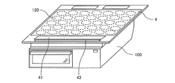
- FIG. It is a perspective view which shows schematic structure of the induction heating cooking appliance which concerns on Embodiment 5.
- FIG. (Constitution) 1 is an exploded perspective view showing an induction heating cooker in the cooking system according to Embodiment 1.
- an induction heating cooker 100 has a top plate 4 on which a heated object 5 such as a pan and a load such as a cooking device 200 are placed.
- FIG. 1 illustrates an example in which the object to be heated 5 is placed as a load.
- the top plate 4 includes a first heating port 1, a second heating port 2, and a third heating port 3 as heating ports for inductively heating the article to be heated 5, and corresponds to each heating port.
- the first heating means 11, the second heating means 12, and the third heating means 13 are provided, and the object to be heated 5 can be placed on the respective heating ports to perform induction heating. Is.
- the first heating means 11 and the second heating means 12 are provided side by side on the front side of the main body, and the third heating means 13 is provided at substantially the center on the back side of the main body.
- positioning of each heating port is not restricted to this.
- three heating ports may be arranged side by side in a substantially straight line.
- the top plate 4 is entirely made of a material that transmits infrared rays, such as heat-resistant tempered glass or crystallized glass, and is watertight through a rubber packing or a sealing material between the outer periphery of the top opening of the induction heating cooker 100. Fixed to state.
- the top plate 4 has a circular shape indicating a rough placement position of the pan corresponding to the heating range (heating port) of the first heating means 11, the second heating means 12, and the third heating means 13.
- the pan position indication is formed by applying paint or printing.
- an operation unit 40a, an operation unit 40b, and an operation unit 40c are provided as input devices for setting a water heating mode, a fried food mode, a cooking device cooking mode, and the like. Yes. Further, in the vicinity of the operation unit 40, as the notification unit 42, a display unit 41a, a display unit 41b, and a display unit 41c for displaying the operation state of the induction heating cooker 100, the input / operation content from the operation unit 40, and the like. Is provided.
- the operation units 40a to 40c and the display units 41a to 41c are not particularly limited, for example, when the operation units 40a and 41c are provided for each heating port, or when the operation unit 40 and the display unit 41 are provided collectively.
- the operation units 40a to 40c are configured by mechanical switches such as push switches and tact switches, touch switches for detecting input operations based on changes in electrode capacitance, and the like.
- the display units 41a to 41c are configured by, for example, an LCD (Liquid Crystal Device), an LED, or the like.
- LCD Liquid Crystal Device
- the display operation unit 43 is configured by, for example, a touch panel in which touch switches are arranged on the upper surface of the LCD.
- a first heating means 11, a second heating means 12, and a third heating means 13 are provided below the top plate 4 and inside the induction heating cooker 100.
- Each heating means is a coil. It consists of It should be noted that an electric heater (for example, a nichrome wire, a halogen heater, or a radiant heater) that heats at least one of the first heating means 11, the second heating means 12, and the third heating means 13 by, for example, radiation. You may comprise.
- the coil is configured by winding a conductive wire made of an arbitrary metal with an insulating film (for example, copper, aluminum, etc.).
- a high frequency magnetic field is generated from each coil by supplying a high frequency current to each coil by the drive circuit 50.
- the induction heating cooker 100 includes a drive circuit 50 for supplying high-frequency power to the coils of the first heating means 11, the second heating means 12, and the third heating means 13, and the drive circuit 50.
- a control unit 45 for controlling the operation of the whole cooking device is provided.
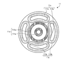
- FIG. 2 is a diagram showing first heating means of the induction heating cooker according to the first embodiment.
- the 1st heating means 11 is comprised by the inner periphery coil 11a arrange
- the outer periphery of the first heating unit 11 has a substantially circular shape corresponding to the first heating port 1.
- the inner peripheral coil 11a is composed of an inner peripheral inner coil 111a and an inner peripheral outer coil 112a that are arranged substantially concentrically.
- the inner circumference inner coil 111a and the inner circumference outer coil 112a have a circular planar shape, and a conductive wire made of any metal (for example, copper, aluminum, etc.) coated with an insulating film is wound in the circumferential direction. It is configured.
- the inner circumference inner coil 111 a and the inner circumference outer coil 112 a are connected in series and driven and controlled by one drive circuit 50. Note that the inner circumference inner coil 111a and the inner circumference outer coil 112a may be connected in parallel, or may be driven using independent drive circuits (inverter circuits).
- the outer peripheral coil 11b is composed of an outer peripheral left coil 111b and an outer peripheral right coil 112b.
- the outer peripheral coil 11c includes an outer peripheral upper coil 111c and an outer peripheral lower coil 112c.
- the outer peripheral left coil 111b and the outer peripheral right coil 112b are connected in series and are driven and controlled by one drive circuit 50.
- the outer periphery upper coil 111 c and the outer periphery lower coil 112 c are connected in series and are driven and controlled by one drive circuit 50.
- outer peripheral left coil 111b, the outer peripheral right coil 112b, the outer peripheral upper coil 111c, and the outer peripheral lower coil 112c are substantially aligned with the circular outer shape of the inner peripheral coil 11a. It is arranged around.
- the four outer coils have a substantially 1 ⁇ 4 arc shape (banana shape or pepper shape) planar shape, and conductive wires made of any metal (for example, copper, aluminum, etc.) coated with an insulating film are connected to the outer coil. It is configured by winding along a quarter arc shape.
- the outer peripheral coil is configured to extend substantially along the circular planar shape of the inner peripheral coil 11a in a 1 ⁇ 4 arc-shaped region adjacent to the inner peripheral coil 11a.
- the number of outer peripheral coils is not limited to four.
- the shape of the outer peripheral coil is not limited to this. For example, a configuration using a plurality of circular outer peripheral coils may be used.
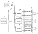
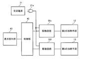
- FIG. 3 is a block diagram showing a drive circuit of the first heating means of the induction heating cooker according to the first embodiment.
- the first heating unit 11 is driven and controlled by driving circuits 50a, 50b, and 50c. That is, the inner circumference inner coil 111a and the inner circumference outer coil 112a constituting the inner circumference coil 11a are driven and controlled by the drive circuit 50a.
- the outer peripheral left coil 111b and the outer peripheral right coil 112b constituting the outer peripheral coil 11b are driven and controlled by the drive circuit 50b.
- the outer peripheral upper coil 111c and the outer peripheral lower coil 112c constituting the outer peripheral coil 11c are driven and controlled by the drive circuit 50c.
- AC power (commercial power) 21 is supplied from one AC power supply unit 21a to the drive circuits 50a, 50b, and 50c. That is, the supply of the AC power supply 21 to the induction heating cooker 100 is configured by only one AC power supply unit 21a.
- the AC power supply unit 21a is configured by a power plug connected to an outlet to which the AC power supply 21 is fed. Note that the configuration of the AC power supply unit 21a is not limited to this, and may be configured by, for example, a connection terminal connected to a power cable to which the AC power supply 21 is fed. For example, a round terminal or the like may be used as the connection terminal, and the end of the power cable may be arranged on the round terminal and fixed with screws.
- FIG. 3 shows a case where the drive circuits 50a, 50b, and 50c for driving the first heating unit 11 are supplied with the AC power supply 21 through one AC power supply unit 21a. Is not limited to this. All the drive circuits that drive the first heating means 11, the second heating means 12, and the third heating means 13 may be configured to be supplied with the AC power supply 21 through one AC power supply section 21a. good.
- the control unit 45 includes a microcomputer or a DSP (digital signal processor).
- the control unit 45 controls the drive circuits 50a, 50b, and 50c based on the operation content from the display operation unit 43 and the like. In addition, the control unit 45 performs display on the display operation unit 43 according to the operation state.
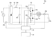
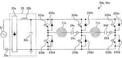
- FIG. 4 is a diagram illustrating a drive circuit of the induction heating cooker according to the first embodiment.
- the drive circuit 50 is provided for every heating means, the circuit structure may be the same and may be changed for every heating means.
- FIG. 4 shows a drive circuit 50a for driving the inner peripheral coil 11a.
- the drive circuit 50a includes a DC power supply circuit 22, an inverter circuit 23, and a resonance capacitor 24a.
- the input current detection means 25a is constituted by, for example, a current sensor, detects a current input from the AC power supply 21 to the DC power supply circuit 22, and outputs a voltage signal corresponding to the input current value to the control unit 45.
- the DC power supply circuit 22 includes a diode bridge 22a, a reactor 22b, and a smoothing capacitor 22c, converts an AC voltage input from the AC power supply 21 into a DC voltage, and outputs the DC voltage to the inverter circuit 23.
- the inverter circuit 23 is a so-called half-bridge type inverter in which IGBTs 23a and 23b as switching elements are connected in series to the output of the DC power supply circuit 22, and diodes 23c and 23d are parallel to the IGBTs 23a and 23b as flywheel diodes, respectively. It is connected to the.
- the IGBT 23 a and the IGBT 23 b are driven on and off by a drive signal output from the control unit 45.
- the control unit 45 turns off the IGBT 23b while turning on the IGBT 23a, turns on the IGBT 23b while turning off the IGBT 23a, and outputs a drive signal that turns on and off alternately.
- the inverter circuit 23 converts the DC power output from the DC power supply circuit 22 into a high-frequency AC power of about 20 kHz to 100 kHz, and supplies the power to the resonance circuit including the inner peripheral coil 11a and the resonance capacitor 24a. .
- the resonant capacitor 24a is connected in series to the inner peripheral coil 11a, and this resonant circuit has a resonant frequency corresponding to the inductance of the inner peripheral coil 11a, the capacity of the resonant capacitor 24a, and the like.
- the inductance of the inner peripheral coil 11a changes according to the characteristics of the metal load when the object to be heated 5 (metal load) is magnetically coupled, and the resonance frequency of the resonance circuit changes according to the change in the inductance.
- the IGBTs 23a and 23b which are switching elements, are composed of, for example, a silicon-based semiconductor, but may be configured using a wide band gap semiconductor such as silicon carbide or a gallium nitride-based material.
- the conduction loss of the switching element can be reduced, and since the heat radiation of the driving circuit is good even when the switching frequency (driving frequency) is high (high speed), the driving circuit Therefore, the size and cost of the driving circuit can be reduced.
- the coil current detection means 25b is connected to a resonance circuit composed of the inner peripheral coil 11a and the resonance capacitor 24a.
- the coil current detection means 25b is constituted by, for example, a current sensor, detects a current flowing through the inner peripheral coil 11a, and outputs a voltage signal corresponding to the coil current value to the control unit 45.
- the drive circuit 50a for driving the inner peripheral coil 11a has been described. However, the same configuration can be applied to the drive circuit 50b for driving the outer peripheral coil 11b and the drive circuit 50c for driving the outer peripheral coil 11c. . Note that the drive circuits 50 a, 50 b, and 50 c may be connected in parallel to the AC power supply 21.
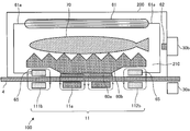
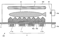
- FIG. 5 is a schematic diagram illustrating a configuration of the induction heating cooker and the cooking apparatus in the heating cooking system according to Embodiment 1.
- the cooking system includes an induction heating cooker 100 and a cooking device 200.
- the state by which the cooking apparatus 200 is mounted on the top plate 4 of the induction heating cooking appliance 100 is shown.
- the longitudinal cross-section which looked at the induction heating cooking appliance 100 and the cooking apparatus 200 from the front side is shown typically. Yes.
- the inner peripheral coil 11a and the outer peripheral coil 11b are arranged under the top plate 4 of the induction heating cooker 100.
- illustration of the outer peripheral upper coil 111c and the outer peripheral lower coil 112c constituting the outer peripheral coil 11c is omitted.
- the arrows shown around the inner peripheral coil 11a and the magnetic body 60a and the arrows shown around the outer peripheral left coil 111b, the outer peripheral right coil 112b, and the power receiving coil 65 indicate magnetic flux lines.
- the induction heating cooker 100 is provided with a primary transmission / reception unit 30a that communicates with the cooking device 200.
- the primary transmission / reception unit 30a is configured by a wireless communication interface conforming to an arbitrary communication standard such as Wi-Fi (registered trademark), Bluetooth (registered trademark), infrared communication, NFC (near field communication), and the like.
- the primary transmission / reception unit 30a performs two-way information communication with the secondary transmission / reception unit 30b of the cooking apparatus 200.
- the cooking apparatus 200 is an apparatus that cooks an object 70 such as a fish.
- Cooking device 200 is detachably supported by induction heating cooker 100.
- the cooking device 200 is placed on the top plate 4 of the induction heating cooker 100.
- a heating chamber 210 in which an object to be cooked 70 is accommodated is formed inside the casing.
- the cooking apparatus 200 includes a magnetic body 60a, a cooking table 60b, an upper surface heater 61, a temperature sensor 62, a power receiving coil 65, and a secondary transmission / reception unit 30b.
- the magnetic body 60 a is formed of a magnetic material such as iron, for example, and is disposed on the bottom surface of the cooking apparatus 200.
- the magnetic body 60a is induction-heated when it is placed in a high-frequency magnetic field generated by the inner peripheral coil 11a inside the induction heating cooker 100.
- the upper surface of the cooking table 60b has corrugated irregularities, and an object 70 such as fish is placed on the upper surface.
- the cooking table 60b is disposed in contact with the upper surface of the magnetic body 60a, for example, and the object to be cooked 70 is placed thereon.
- the cooking table 60b is made of, for example, a nonmagnetic metal such as aluminum, and is thermally coupled (joined) to the magnetic body 60a.
- the position of the cooking table 60b should just be arrange
- it may replace with the magnetic body 60a and the cooking stand 60b, and the structure which detachably accommodates in the heating chamber 210 the cooking pan, the pan, etc. which are the to-be-heated material to be heated by induction may be sufficient.
- both the magnetic body 60a and the cooking table 60b may be made of a magnetic material such as iron, or may be integrated with the magnetic material.
- the power receiving coil 65 is disposed on the bottom surface of the cooking apparatus 200.
- the power receiving coil 65 is configured by winding a conductive wire made of an arbitrary metal (for example, copper, aluminum, etc.) coated with an insulating film in the circumferential direction.
- the power receiving coil 65 receives power by electromagnetic induction or magnetic field resonance.
- the upper surface heater 61 is connected to the power receiving coil 65 by a wiring 61a.
- the upper surface heater 61 is configured by a heating element that generates heat (drives) by the power received by the power receiving coil 65.
- a sheathed heater that is a resistance heating element is used.
- the upper surface heater 61 is not limited to a specific configuration, and an arbitrary heating element such as a halogen heater or a far infrared heater can be used.
- the temperature sensor 62 is disposed in the heating chamber 210 and detects the temperature in the heating chamber 210.
- the temperature sensor 62 for example, a platinum resistance temperature detector, a thermistor, a thermocouple, or the like is used.
- a plurality of temperature sensors 62 may be provided as necessary. Further, the arrangement of the temperature sensor 62 is not limited to the wall surface of the heating chamber 210, and may be provided on the top surface, the bottom surface, or the cooking table 60b as necessary. Moreover, you may provide the non-contact-type temperature sensor 62 which detects the amount of infrared rays radiated
- the secondary transmission / reception unit 30b is configured by a wireless communication interface conforming to the communication standard of the primary transmission / reception unit 30a.
- the secondary transmission / reception unit 30b communicates information bidirectionally with the primary transmission / reception unit 30a of the induction heating cooker 100.
- the secondary transmission / reception unit 30b includes information on the temperature detected by the temperature sensor 62, information added to the cooking apparatus 200, information indicating the type of equipment of the cooking apparatus 200, information on equipment specifications of the cooking apparatus 200, and the like. It transmits to the primary transmission / reception part 30a.
- released may be sufficient.
- the outer shell of the cooking device 200 may be configured only by both side surfaces and the upper surface, and the front surface, the rear surface, and the bottom surface of the cooking device 200 may be open. In this case, a space surrounded by both side surfaces and the upper surface of the cooking apparatus 200 and the top plate 4 of the induction heating cooker 100 constitutes the heating chamber 210.
- the magnetic body 60 a and the power receiving coil 65 of the cooking apparatus 200 are arranged at positions corresponding to the coils arranged under the top plate 4 of the induction heating cooker 100.
- the positional relationship between the magnetic body 60 a and the power receiving coil 65 is arranged at a position corresponding to the positional relationship between the inner peripheral coil 11 a and the outer peripheral coils 11 b and 11 c of the first heating unit 11. An example will be described with reference to FIG.
- FIG. 6 is a top view schematically showing the configuration of the cooking device of the heating cooking system according to Embodiment 1.
- FIG. 6 in the cooking apparatus 200, for example, a magnetic body 60a and a power receiving coil 65 are disposed below a circular cooking table 60b.
- the magnetic body 60a is formed in a disk shape having an outer diameter substantially the same as the outer diameter of the inner peripheral coil 11a of the induction heating cooker 100. That is, in a state where the cooking apparatus 200 is placed on the top plate 4 of the induction heating cooker 100, the magnetic body 60a of the cooking apparatus 200 is disposed so as to overlap the inner peripheral coil 11a of the induction heating cooker 100 in the vertical direction.
- the magnetic body 60a has a shape that does not overlap with the outer peripheral coils 11b and 11c in the vertical direction.
- the four receiving coils 65 are provided around the magnetic body 60 a corresponding to the outer peripheral coils 11 b and 11 c of the induction heating cooker 100.
- the four power receiving coils 65 have substantially the same shape as the shape of the outer peripheral coils 11b and 11c of the induction heating cooker 100. That is, the four power receiving coils 65 have a substantially 1 ⁇ 4 arc shape (banana shape or pepper shape) planar shape, and a conductive wire made of any metal (for example, copper, aluminum, etc.) coated with an insulating film.
- the power receiving coil 65 is configured by being wound along a quarter arc shape.
- the power receiving coil 65 of the cooking apparatus 200 is preferably arranged so as not to overlap the inner peripheral coil 11a of the induction heating cooker 100 in the vertical direction but only to the outer peripheral coils 11b and 11c.
- the position of the power receiving coil 65 may be any position as long as it is disposed above at least a part of the outer peripheral coils 11b and 11c when the magnetic body 60a is disposed above the inner peripheral coil 11a. It is not limited to the position.
- the number of power receiving coils 65 is not limited to this, and may be at least one.
- the structure which provides the several receiving coil 65 with respect to one outer periphery coil may be sufficient.
- the magnetic body 60a and the inner peripheral coil 11a are arranged so as to overlap in the vertical direction.
- the magnetic body 60a is induction heated by the high frequency magnetic flux (high frequency magnetic field) generated from the inner peripheral coil 11a.
- the heat generated in the magnetic body 60a is thermally conducted to the thermally coupled cooking table 60b.
- the to-be-cooked object 70 placed on the cooking table 60b is cooked from below.
- the power receiving coil 65 and the outer peripheral coils 11b and 11c are arranged so as to overlap in the vertical direction.
- a high frequency current is supplied from the drive circuits 50b and 50c to the outer coils 11b and 11c
- a high frequency magnetic flux (high frequency magnetic field) is generated from the outer coils 11b and 11c.
- high frequency magnetic flux (high frequency magnetic field) is generated from the outer peripheral coils 11b and 11c
- electric power (electromotive force) due to electromagnetic induction is generated in the power receiving coil 65 of the cooking apparatus 200.
- the electric power generated in the power receiving coil 65 is supplied to the upper surface heater 61. Thereby, the upper surface heater 61 generates heat, and the cooking object 70 placed on the cooking table 60b is cooked from above by heat radiation.
- the inner peripheral coil 11a of the induction heating cooker 100 is used as an induction heating coil for induction heating the magnetic body 60a of the cooking apparatus 200.
- the outer peripheral coils 11 b and 11 c of the induction heating cooker 100 are used as power supply coils for performing non-contact power transmission to the upper surface heater 61 of the cooking apparatus 200. That is, the cooking by induction heating and the cooking by electric power received by non-contact power transmission are simultaneously performed on one object 70 to be cooked.
- the high-frequency current supplied from the drive circuit 50a to the inner peripheral coil 11a corresponds to the “first high-frequency current” in the present invention.
- the high frequency magnetic flux (high frequency magnetic field) generated from the inner peripheral coil 11a corresponds to the “first high frequency magnetic field” in the present invention.
- the high-frequency current supplied from the drive circuits 50b and 50c to the outer peripheral coils 11b and 11c corresponds to the “second high-frequency current” in the present invention.
- the high-frequency magnetic flux (high-frequency magnetic field) generated from the outer peripheral coils 11b and 11c corresponds to the “second high-frequency magnetic field” in the present invention.
- ferrite as a magnetic material on the lower surfaces of the inner peripheral coil 11 a and the outer peripheral coils 11 b and 11 c of the induction heating cooker 100. Further, it is desirable to similarly provide ferrite on the upper surface of the power receiving coil 65 of the cooking apparatus 200.
- the outer peripheral coils 11b and 11c are used as power feeding coils, the high frequency magnetic flux is easily interlinked by providing ferrite, and the leakage magnetic flux is reduced. Thereby, the high frequency power can be more effectively supplied to the power receiving coil 65, the power conversion efficiency is high, and the loss can be reduced.
- the high frequency magnetic flux from the inner peripheral coil 11a and the high frequency magnetic flux from the outer peripheral coils 11b and 11c can be reduced. Interference is reduced. For this reason, the loss in non-contact electric power transmission at the time of using the outer periphery coils 11b and 11c as a feed coil can reduce, and can improve electric power transmission efficiency more.
- the inner coil 11a corresponds to the “first coil” of the present invention.
- the inverter circuit 23 of the drive circuit 50a corresponds to the “first inverter circuit” of the present invention, and may include the DC power supply circuit 22 of the drive circuit 50a.
- the outer coils 11b and 11c correspond to the “second coil” of the present invention.
- the inverter circuit 23 of the drive circuits 50b and 50c corresponds to the “second inverter circuit” of the present invention, and may include the DC power supply circuit 22 of the drive circuits 50b and 50c.
- the magnetic body 60a corresponds to the “object to be heated” of the present invention.
- the upper surface heater 61 corresponds to “cooking means” of the present invention.
- the control unit 45 corresponds to a “control device” of the present invention.
- the user places an object to be cooked 70 such as a fish on the cooking table 60b inside the cooking apparatus 200.
- the user places the cooking device 200 on the heating port of the top plate 4 of the induction heating cooker 100.
- the following description demonstrates the case where the cooking apparatus 200 is mounted in the 1st heating port 1 (1st heating means 11).
- the user instructs to start cooking (throwing in thermal power) at the display operation unit 43.
- the display operation unit 43 incorporates a dedicated mode (menu) for operating the cooking apparatus 200, and can be easily cooked by selecting the dedicated mode.
- the control unit 45 of the induction heating cooker 100 controls the drive circuit 50a according to the heating power to be induction-heated, and performs a heating operation of supplying high-frequency power to the inner peripheral coil 11a.
- positioned at the lower surface of the cooking table 60b of the cooking apparatus 200 is induction-heated.
- the heat generated by the magnetic body 60a due to induction heating is transferred to the non-magnetic cooking table 60b, and the cooking object 70 placed on the upper surface of the cooking table 60b is directly heated from the lower surface.
- the control unit 45 of the induction heating cooker 100 controls the drive circuits 50b and 50c in accordance with the power transmitted to the power receiving coil 65, respectively, and supplies high-frequency power to the outer peripheral coils 11b and 11c. I do.
- the high frequency electric power supplied from the outer peripheral coils 11b and 11c is received by the power receiving coil 65 arranged on the lower surface of the cooking apparatus 200.
- the received power is supplied to the upper surface heater 61, and the upper surface heater 61 generates heat.
- the upper surface heater 61 heats the to-be-cooked object 70 placed on the upper surface of the cooking table 60b from the upper surface by heat radiation.
- the rated power of the cooking apparatus 200 is 1500 W, for example.
- the control unit 45 controls the driving of the drive circuits 50b and 50c so that the power received by the power receiving coil 65 is equal to or lower than the rated power (1500 W).
- the control unit 45 may control the drive circuits 50 a, 50 b, and 50 c according to the temperature detected by the temperature sensor 62.
- the control unit 45 acquires information about the temperature detected by the temperature sensor 62 of the cooking apparatus 200 via the primary transmission / reception unit 30a.
- the control part 45 is set so that the temperature in the heating chamber 210 of the cooking device 200 may become a desired temperature according to the preset temperature set by the display operation part 43 or the temperature preset by the cooking menu.
- the drive of the drive circuits 50a, 50b, 50c is controlled to control the heat generation amount (thermal power) of the magnetic body 60a and the upper surface heater 61.
- a plurality of temperature sensors 62 may be provided in the vertical direction in the heating chamber 210.
- the control unit 45 controls the heating power (power supplied to the inner peripheral coil 11a) for induction heating the magnetic body 60a according to the temperature detected by the temperature sensor 62 provided on the lower side. Further, the control unit 45 controls the heating power of the upper surface heater 61 (power supplied to the outer peripheral coils 11b and 11c) according to the temperature detected by the temperature sensor 62 provided on the upper side.
- the induction heating cooker 100 is provided separately from the drive circuit 50a for supplying the high frequency current to the inner peripheral coil 11a and the drive circuit 50a, and the high frequency is applied to the outer peripheral coils 11b and 11c.
- Drive circuits 50b and 50c for supplying current are provided.
- the cooking apparatus 200 includes a power receiving coil 65 that receives power from the outer peripheral coils 11b and 11c, and a top heater 61 that generates heat by the power received by the power receiving coil 65. For this reason, cooking by induction heating and cooking by non-contact power transmission can be performed simultaneously. Moreover, cooking by induction heating and cooking by non-contact power transmission can be individually controlled. Therefore, an induction heating cooker that can be deliciously cooked in a short time can be obtained.
- the temperature sensor 62 which detects the temperature in the heating chamber 210 of the cooking apparatus 200, and the secondary transmission / reception part 30b which transmits the information of the detected temperature are provided.
- the control unit 45 acquires information on the temperature detected by the temperature sensor 62 via the primary transmission / reception unit 30a. And the control part 45 controls the drive of the drive circuit 50a and the drive circuits 50b and 50c according to the temperature which the temperature sensor 62 detected, respectively. For this reason, the control part 45 can control separately the heating by induction heating and the heating by non-contact electric power transmission according to the temperature detected by the temperature sensor 62. Therefore, the internal temperature of the cooking apparatus 200 and the temperature of the cooking dish can be finely controlled, and cooking can be easily performed with few failures.
- an AC power supply unit 21a connected to the AC power supply 21 is provided, and the plurality of drive circuits are supplied with the AC power supply 21 through one AC power supply unit 21a. For this reason, the workability at the time of installing the induction heating cooking appliance 100 can be improved.
- the outer periphery coils 11b and 11c demonstrated four coils
- the number of coils is not this limitation.
- the four coils are driven by the two drive circuits 50
- the combination of the coil and the drive circuit (inverter circuit) is not particularly limited, and the same effect can be obtained by driving the four coils individually. Play.
- the to-be-heated material 5 such as a pan is mounted, and an inner peripheral coil is mounted.
- 11a and outer peripheral coils 11b and 11c as induction heating coils, the entire surface of the heating port can also be induction heated.
- induction heating the entire surface of the heating port it is possible to increase the area of the induction heating unit, and it is possible to obtain an induction heating cooker that can realize sufficient heating even when a large pan is used.
- the input power of the inner peripheral coil 11a and the outer peripheral coils 11b and 11c can be individually controlled.
- the induction heating part can be switched by sequentially switching energization to the inner peripheral coil 11a and the outer peripheral coils 11b and 11c.
- convection stew can be realized at the time of cooking boiled food, and an induction heating cooker capable of cooking deliciously can be obtained.
- the heating cooking system provided with the induction heating cooking appliance 100 and the cooking apparatus 200 was demonstrated, this invention is not restricted to this, All the components of the cooking apparatus 200 are induction-heated.
- the cooking device 100 may be provided, and the cooking device 200 may be omitted.
- the induction heating cooker 100 may include a part of the configuration of the cooking apparatus 200.
- FIG. 7 is a schematic diagram illustrating a modified example of the cooking apparatus in the heat cooking system according to the first embodiment.
- the cooking device 200 shown in FIG. 7 includes a stirring device 80 as cooking means that is driven by the power received by the power receiving coil 65.
- the stirring device 80 includes a motor 81, a shaft 82, and a blade portion 83.
- the motor 81 is provided, for example, in the upper part of the casing of the cooking apparatus 200 and is driven to rotate by the power received by the power receiving coil 65.
- the shaft 82 has a rotational axis arranged in the vertical direction, and one end is connected to the motor 81 to transmit the driving force of the motor 81.
- the blade portion 83 is attached to the shaft 82 and agitates the food 70 by the rotational driving of the shaft 82.
- the bottom surface of the casing constituting the outer shell is opened.
- the bottom surface of the casing of the cooking apparatus 200 is open at least in a range overlapping with the inner peripheral coil 11a of the induction heating cooker 100 in the vertical direction.
- a heated object 5 such as a pan or a frying pan into which an object 70 to be cooked such as stew or fried food is placed is placed on the top plate 4 so as to overlap the inner peripheral coil 11a in the vertical direction. Then, the blade
- FIG. When a high frequency current is supplied from the drive circuit 50a to the inner peripheral coil 11a, the object to be heated 5 is induction heated by the high frequency magnetic flux (high frequency magnetic field) generated from the inner peripheral coil 11a. Thereby, the to-be-cooked item 70 in the to-be-heated item 5 is cooked from below.
- a high frequency magnetic flux (high frequency magnetic field) is generated from the outer coils 11b and 11c.
- high frequency magnetic flux (high frequency magnetic field) is generated from the outer peripheral coils 11b and 11c, electric power (electromotive force) due to electromagnetic induction is generated in the power receiving coil 65 of the cooking apparatus 200.
- the power generated in the power receiving coil 65 is supplied to the stirring device 80, the motor 81 is driven, and the blade portion 83 is rotationally driven via the shaft 82. Thereby, the to-be-cooked object 70 in the to-be-heated object 5 is stirred and cooked.
- cooking by induction heating and stirring cooking by non-contact power transmission can be performed simultaneously. Moreover, heating cooking by induction heating and stirring cooking by non-contact power transmission can be individually controlled. Therefore, an induction heating cooker that can be deliciously cooked in a short time can be obtained.
- the power receiving coil 65 may be provided corresponding to only a part of the outer peripheral coil 11b and the outer peripheral coil 11c.
- the receiving coil 65 corresponding to at least 1 coil among the outer periphery left coil 111b, the outer periphery right coil 112b, the outer periphery upper coil 111c, and the outer periphery lower coil 112c.
- a coil other than the coil corresponding to the power receiving coil 65 may be operated as a coil for induction heating the article to be heated 5.
- a position display indicating the mounting position of the object to be heated 5 and a position display indicating the mounting position of the power receiving coil 65 are applied or printed. It may be formed by such as.
- a cooking means is not limited to this.
- a cooling device having a Peltier element may be provided as cooking means driven by the power received by the power receiving coil 65.
- heating cooking by induction heating and cooling cooking by non-contact power transmission can be performed simultaneously or sequentially. Therefore, the wide cooking which can adjust the temperature range given to the to-be-heated material 5 and the to-be-cooked object 70 in a wide range can be performed.
- a cooking means that is driven by the power received by the power receiving coil 65 for example, a device that flips the cooking object 70 on the heating object 5 up and down may be provided.
- the upper and lower surfaces of the object 70 can be brought into contact with the object 5 to be heated. Therefore, for example, burnt eyes generated by the contact between the object to be heated 5 and the object to be cooked 70 can be applied to both surfaces of the object to be cooked 70.
- FIG. 8 is a diagram illustrating another drive circuit of the induction heating cooker according to the first embodiment.
- the drive circuit 50a shown in FIG. 8 is configured by a so-called full-bridge inverter in which IGBTs 232a and 232b as switching elements and diodes 232c and 232d as flywheel diodes are additionally connected to the inverter circuit 23 of FIG. Has been.
- Other configurations are the same as those in FIG. 4, and the same portions are denoted by the same reference numerals.
- the control unit 45 outputs a drive signal for driving each switching element (IGBT 231a, 231b, 232a, 232b) of the inverter circuit 23, and the electric power input to the inner peripheral coil 11a is a heating operation similarly to the above-described operation.
- the power is controlled so as to be the power set in. Even in such a configuration, the same effect can be obtained.
- FIG. 9 is a diagram showing another drive circuit of the induction heating cooker according to the first embodiment.
- the driving circuit 50b for driving the outer peripheral coil 11b and the driving circuit 50c for driving the outer peripheral coil 11c are configured by a full bridge type inverter circuit, and one of the arms configuring the full bridge. Is a common arm.
- the drive circuits 50b and 50c are composed of full-bridge inverters as in FIG.
- the arm composed of two IBGTs 234a and 234b is used as a common arm, the outer coil 11b (feed coil) is driven and controlled by the IGBT 233a and 233b and the common arm, and the outer coil 11c (feed coil) is driven by the IGBT 235a and 235b and the common arm. It is the structure to control. Even in such a configuration, the outer peripheral coil 11b and the outer peripheral coil 11c can be driven and controlled, and the same effects as those described above can be obtained.
- FIG. 10 is a diagram showing another first heating unit of the induction heating cooker according to the first embodiment.
- the first heating means 11 shown in FIG. 10 includes an inner peripheral coil 11a disposed at the center of the heating port, and an outer peripheral coil 11d disposed substantially concentrically with the inner peripheral coil 11a.
- the inner peripheral coil 11a includes an inner peripheral inner coil 111a and an inner peripheral outer coil 112a, which are connected in series, and are driven and controlled by the drive circuit 50a.
- the outer peripheral coil 11d has an outer peripheral inner coil 111d and an outer peripheral outer coil 112d that are formed concentrically with the inner peripheral coil 11a.
- the outer periphery inner coil 111d and the outer periphery outer coil 112d are respectively connected in series and driven and controlled by the drive circuit 50d.
- the configuration of the drive circuit 50d is the same as that of the drive circuit 50a described above.
- the receiving coil 65 of the cooking apparatus 200 in this configuration example is formed concentrically with the center of the magnetic body 60a corresponding to the shape of the outer peripheral coil 11d.
- the inner peripheral coil 11a of the induction heating cooker 100 is used as an induction heating coil for heating the magnetic body 60a of the cooking apparatus 200.
- the outer periphery coil 11d can acquire the effect similar to the effect mentioned above by being used as a feeding coil for performing non-contact electric power transmission to the upper surface heater 61 of the cooking apparatus 200.
- the coil configuration is simpler than the above-described coil configuration in FIG. 2, an equivalent effect can be obtained with an inexpensive configuration.
- FIG. FIG. 11 and FIG. 12 are block diagrams showing the configuration of the cooking device of the heat cooking system according to the second embodiment.
- FIG. 13 is a top view schematically showing the configuration of the cooking device of the heating cooking system according to the second embodiment.
- FIG. 11 FIG. 12, the state by which the cooking apparatus 200 is mounted on the top plate 4 of the induction heating cooking appliance 100 is shown.
- FIG. 11 the longitudinal cross section which looked at the induction heating cooking appliance 100 and the cooking apparatus 200 from the front side is shown typically.
- FIG. 12 the longitudinal cross section which looked at the induction heating cooking appliance 100 and the cooking apparatus 200 from the side surface side is shown typically.
- the difference from the first embodiment will be mainly described.
- the magnetic body 60a and the cooking table 60b in the second embodiment are formed in a rectangular shape in a top view.
- the magnetic body 60a and the cooking table 60b are formed such that the length of the long side is longer than the width of the heating port, for example, and the length of the short side is substantially equal to the width (outer diameter) of the inner peripheral coil 11a. It is formed in length.
- the magnetic body 60a and the cooking table 60b are placed on the top 4 so that the long sides of the magnetic body 60a and the cooking table 60b face in the left-right direction, as shown in FIGS.
- the edge part of the outer periphery left coil 111b of the induction heating cooking appliance 100 is arrange
- variety of the front-back direction of the magnetic body 60a and the cooking stand 60b becomes substantially equivalent to the width
- the power receiving coil 65 in the present second embodiment is arranged so as to sandwich the long sides on both sides of the magnetic body 60a and the cooking table 60b, for example.
- Two power receiving coils 65 are provided corresponding to the outer periphery upper coil 111 c and the outer periphery lower coil 112 c of the induction heating cooker 100.
- the two power receiving coils 65 have a substantially 1 ⁇ 4 arc-shaped (banana-shaped or pepper-shaped) planar shape, and receive a conductive wire made of any metal (for example, copper, aluminum, etc.) coated with an insulating film. It is comprised by winding along the 1/4 circular arc shape of 65.
- FIG. 14 is a diagram showing first heating means of the induction heating cooker according to the second embodiment.
- the configuration of the first heating unit 11 is the same as that of the first embodiment, but the drive control in the control unit 45 is different. That is, the control unit 45 controls the drive circuit 50a for driving the inner peripheral coil 11a and the drive circuit 50b for driving the outer peripheral coil 11b (the outer peripheral left coil 111b and the outer peripheral right coil 112b) according to the heating power to be induction-heated. Then, a heating operation for supplying high-frequency power is performed. Thereby, the magnetic body 60a arrange
- the control unit 45 controls the drive circuit 50c according to the power transmitted to the power receiving coil 65, and supplies non-contact power transmission for supplying high frequency power to the outer coil 11c (the outer coil 111c and the lower coil 112c). Perform the action.
- the high frequency power supplied from the outer peripheral coil 11 c is received by the power receiving coil 65 disposed on the lower surface of the cooking apparatus 200.
- the received power is supplied to the upper surface heater 61, and the upper surface heater 61 generates heat.
- the upper surface heater 61 heats the to-be-cooked object 70 placed on the upper surface of the cooking table 60b from the upper surface by heat radiation.
- the widths of the magnetic body 60a and the cooking table 60b are increased, and the magnetic body 60a is induction-heated by the inner peripheral coil 11a and the outer peripheral coil 11b. To do. For this reason, by increasing the area of the lower surface heating by induction heating, it is possible to generate an appropriate burnish from the lower surface. For example, even if the cooking object 70 has a long shape such as fish, the cooking object 70 can be placed on the cooking table 60b, and the cooking object 70 such as fish is cooked deliciously by heating the bottom surface. Is possible.
- the feeding coils for supplying power to the upper surface heater 61 of the cooking apparatus 200 are the outer periphery upper coil 111c and the outer periphery lower coil 112c. Compared with FIG. Less. For this reason, the electric power to the outer periphery upper coil 111c and the outer periphery lower coil 112c is increased so that the electric power supplied to the upper surface heater 61 may not fall. Thereby, the cooking apparatus 200 which can cook deliciously in a short time can be obtained, without impairing cooking time.
- Embodiment 3 a configuration in which cooking by induction heating and cooking by non-contact power transmission is performed using a plurality of heating means will be described.
- the same parts as those in the first embodiment are denoted by the same reference numerals, and the difference from the first embodiment will be mainly described.
- FIG. 15 is a block diagram illustrating a second heating unit and a driving circuit for the third heating unit of the induction heating cooker according to the third embodiment.
- the second heating means 12 is driven and controlled by a drive circuit 50e.
- the third heating unit 13 is driven and controlled by the driving circuit 50f. That is, a coil (not shown) constituting the second heating means 12 is driven and controlled by the drive circuit 50e, and a coil (not shown) constituting the third heating means 13 is driven and controlled by the drive circuit 50f. Is done.
- the second heating means 12 and the third heating means 13 may be configured to include one coil, and, similarly to the first embodiment, an inner peripheral coil and an outer peripheral coil disposed around the inner peripheral coil.
- positioned the several coil concentrically may be sufficient. Further, in the case of a configuration including a plurality of coils, a configuration including a plurality of drive circuits for one heating means may be used.
- AC power (commercial power) 21 is supplied from one AC power supply unit 21a to the drive circuits 50e and 50f. That is, the supply of the AC power supply 21 to the induction heating cooker 100 is configured by only one AC power supply unit 21a.
- the AC power supply unit 21a is configured by a power plug connected to an outlet to which the AC power supply 21 is fed. Note that the configuration of the AC power supply unit 21a is not limited to this, and may be configured by, for example, a connection terminal connected to a power cable to which the AC power supply 21 is fed. For example, a round terminal or the like may be used as the connection terminal, and the end of the power cable may be arranged on the round terminal and fixed with screws.
- the drive circuit 50e for driving the second heating unit 12 and the drive circuit 50f for driving the third heating unit 13 are supplied with the AC power supply 21 through one AC power supply unit 21a.
- the present invention is not limited to this. All the drive circuits that drive the first heating means 11, the second heating means 12, and the third heating means 13 may be configured to be supplied with the AC power supply 21 through one AC power supply section 21a. good.
- FIG. 16 is a schematic diagram illustrating a configuration of an induction heating cooker and a cooking apparatus in the heating cooking system according to the third embodiment.
- the cooking system includes an induction heating cooker 100 and a cooking device 200.
- the state by which the cooking apparatus 200 is mounted on the top plate 4 of the induction heating cooking appliance 100 is shown.
- the to-be-heated material 5 is mounted above the 2nd heating means 12, and the cooking apparatus 200 is mounted above the 2nd heating means 12 and the 3rd heating means 13.
- 1 schematically shows a longitudinal section of the induction heating cooker 100 and the cooking apparatus 200 as viewed from the front side.
- positioning position of the to-be-heated material 5 and the cooking apparatus 200 is not limited to this, It can arrange
- the cooking apparatus 200 includes an upper surface heater 61, a power receiving coil 65, and a support unit 220.
- the power receiving coil 65 is disposed at the bottom of the cooking apparatus 200.
- the power receiving coil 65 is configured by winding a conductive wire made of an arbitrary metal (for example, copper, aluminum, etc.) coated with an insulating film in the circumferential direction.
- the power receiving coil 65 receives power by electromagnetic induction or magnetic field resonance. In the example shown in FIG. 16, the power receiving coil 65 receives power by a high frequency magnetic field generated by a coil constituting the third heating unit 13.
- the upper surface heater 61 is connected to the power receiving coil 65 by wiring (not shown).
- the upper surface heater 61 is configured by a heating element that generates heat (drives) by the power received by the power receiving coil 65.
- a sheathed heater that is a resistance heating element is used.
- the upper surface heater 61 is not limited to a specific configuration, and an arbitrary heating element such as a halogen heater or a far infrared heater can be used. Further, the upper surface heater 61 is supported above the object to be heated 5 by the support means 220.
- the support means 220 is formed by, for example, a casing that constitutes the outline of the cooking apparatus 200.
- the support means 220 is formed in an L-shaped cross section that extends upward from the bottom surface that houses the power receiving coil 65 and then extends in the horizontal direction. That is, when the power receiving coil 65 is disposed above the third heating means 13 (third heating port 3), the support means 220 causes the upper surface heater 61 to move above the second heating means 12 (second heating).
- the upper surface heater 61 is supported so as to be positioned above the mouth 2) and the article 5 to be heated.
- the distance between the top plate 4 and the upper surface heater 61 when the cooking apparatus 200 is arranged on the top plate 4 is set to be higher than the height of a pan, a frying pan, or the like assumed as the article to be heated 5.
- the support means 220 may be configured to drive the upper surface heater 61 in the vertical direction.
- the user places an object to be heated 5 such as a frying pan in the second heating port 2 of the top plate 4.
- the user places the power receiving coil 65 (bottom part of the casing) of the cooking device 200 on the third heating port 3 of the top plate 4.
- the display operation unit 43 instructs the second heating port 2 to start cooking (fire power input) by the user.
- An instruction to start cooking (start feeding) for the third heating port 3 is given by the display operation unit 43.
- the display operation unit 43 incorporates a dedicated mode (menu) for operating the cooking apparatus 200, and can be easily cooked by selecting the dedicated mode.
- the control unit 45 of the induction heating cooker 100 controls the drive circuit 50e in accordance with the heating power to be induction-heated to supply high-frequency power to the coil of the second heating means 12. Perform the action. Thereby, the to-be-heated object 5 mounted in the 2nd heating port 2 is induction-heated. And the to-be-cooked object 70 placed in the to-be-heated object 5 is directly heated from the lower surface.
- the control unit 45 of the induction heating cooker 100 controls the drive circuit 50f according to the power transmitted to the power receiving coil 65 to supply high-frequency power to the coil of the third heating unit 13. I do.
- the high frequency electric power supplied from the coil of the 3rd heating means 13 is received by the receiving coil 65 arrange
- the received power is supplied to the upper surface heater 61, and the upper surface heater 61 generates heat.
- the rated power of the second heating means 12 is, for example, 3000 W.
- the control unit 45 controls the drive of the drive circuit 50e so that the electric power supplied to the coil constituting the second heating unit 12 is equal to or lower than the rated electric power (3000 W).
- the rated power of the cooking apparatus 200 is 1500 W, for example.
- the control unit 45 controls the drive of the drive circuit 50f so that the power received by the power receiving coil 65 is equal to or lower than the rated power (1500 W). That is, it is possible to make the total power of the power for induction heating the object to be heated 5 and the power transmitted to the power receiving coil 65 larger than the rated power of one heating means.
- the cooking apparatus 200 was mounted in the 3rd heating port 3 and non-contact electric power transmission was performed to the receiving coil 65 was demonstrated, not only this but the cooking apparatus 200 is demonstrated.
- the object 5 to be heated may be disposed in the third heating port 3 and the heating operation by the third heating means 13 may be performed.
- the arbitrary heating port among the 1st heating port 1, the 2nd heating port 2, and the 3rd heating port 3 as a heating port for exclusive use which performs non-contact electric power transmission. That is, the display of the top plate 4 that constitutes a dedicated heating port that performs non-contact power transmission functions as a position display that indicates the mounting position of the power receiving coil 65.
- the display of the heating port which places the article to be heated 5 and performs the heating operation corresponds to the “first position display” of the present invention
- the position display indicating the mounting position of the power receiving coil 65 is the display of the present invention. This corresponds to “second position display”.
- the induction heating cooker 100 is provided separately from the drive circuit 50e and the drive circuit 50e that supply the high-frequency current to the coil of the second heating means 12, and the third And a drive circuit 50f for supplying a high-frequency current to the coil of the heating means 13.
- the cooking apparatus 200 includes a power receiving coil 65 that receives power from the coil of the third heating unit 13 and a top heater 61 that generates heat by the power received by the power receiving coil 65. For this reason, cooking by induction heating and cooking by non-contact power transmission can be performed simultaneously. Moreover, cooking by induction heating and cooking by non-contact power transmission can be individually controlled. Therefore, an induction heating cooker that can be deliciously cooked in a short time can be obtained.
- the top surface heating by the top surface heater 61 and the induction heating by the heat from the article to be heated 5 can be individually controlled by the individually provided drive circuit 50e and drive circuit 50f, cooking is delicious in a short time. It is possible to obtain an induction heating cooker that can be used.
- an AC power supply unit 21a connected to the AC power supply 21 is provided, and the plurality of drive circuits are supplied with the AC power supply 21 through one AC power supply unit 21a. For this reason, the workability at the time of installing the induction heating cooking appliance 100 can be improved.
- the heating means that performs induction heating and the heating means that performs non-contact power transmission are different, so that the power for induction heating the object to be heated 5 and the power receiving coil 65 are transmitted. It becomes possible to make the total power with the power to be larger than the rated power of one heating means. Moreover, since all the coils which comprise one heating means are operate
- FIG. 17 is a schematic diagram illustrating a modified example of the cooking apparatus in the heat cooking system according to the third embodiment.
- a cooking device 200 shown in FIG. 17 includes a stirring device 80 as cooking means that is driven by the power received by the power receiving coil 65.
- the structure of the stirring apparatus 80 is the same as that of the modification 1 in the said Embodiment 1, the same code
- the stirring apparatus 200 shown in FIG. 17 for example, when a heated object 5 such as a pan or a frying pan into which an object 70 to be cooked such as stew or fried food is placed is placed on the second heating port 2, the stirring apparatus. 80 blade parts 83 are arranged in the article to be heated 5.
- the object to be heated 5 is induction heated by the high frequency magnetic flux (high frequency magnetic field) generated from the coil. Thereby, the to-be-cooked item 70 in the to-be-heated item 5 is cooked from below.
- cooking by induction heating and stirring cooking by non-contact power transmission can be performed simultaneously. Moreover, heating cooking by induction heating and stirring cooking by non-contact power transmission can be individually controlled. Therefore, an induction heating cooker that can be deliciously cooked in a short time can be obtained.
- a cooking means is not limited to this.
- a cooling device having a Peltier element may be provided as cooking means driven by the power received by the power receiving coil 65.
- heating cooking by induction heating and cooling cooking by non-contact power transmission can be performed simultaneously or sequentially. Therefore, the wide cooking which can adjust the temperature range given to the to-be-heated material 5 and the to-be-cooked object 70 in a wide range can be performed.
- a device that inverts the object 70 to be cooked on the object to be heated 5 may be provided.
- the both surfaces of the up-down direction of the to-be-cooked object 70 can be made to contact the to-be-heated object 5. Therefore, for example, burnt eyes generated by the contact between the object to be heated 5 and the object to be cooked 70 can be applied to both surfaces of the object to be cooked 70.
- Embodiment 4 it is detected whether any of the magnetic body 60a or the power receiving coil 65 of the cooking apparatus 200 is placed above the coil of the induction heating cooker 100, and according to the detection result. The operation for switching between the heating operation and the non-contact power transmission operation will be described.
- the configuration of induction heating cooker 100 in the fourth embodiment is the same as that of the first embodiment, and the configuration of cooking apparatus 200 is the same as that of any of the first to third embodiments.
- control unit 45 When the user places the cooking device 200 on the heating port and instructs the display operation unit 43 to start heating (heating power input), the control unit 45 (load determination unit) performs load determination processing. Note that the control unit 45 in the fourth embodiment includes the function of the “load determination unit” of the present invention.
- FIG. 18 is a load discrimination characteristic diagram based on the relationship between the coil current and the input current in the induction heating cooker according to the fourth embodiment.
- the control unit 45 stores therein in advance a load determination table in which the relationship between the coil current and the input current shown in FIG. 18 is tabulated. By storing the load determination table therein, the load determination unit can be configured with an inexpensive configuration.
- the control unit 45 drives the inverter circuit 23 with a specific drive signal for load determination for each of the drive circuits, and detects the input current from the output signal of the input current detection means 25a. At the same time, the control unit 45 detects the coil current from the output signal of the coil current detection means 25b. The control unit 45 determines the material of the load placed above the coil from the detected coil current and input current and a load determination table representing the relationship of FIG.
- the control unit 45 determines that the magnetic body 60a of the cooking apparatus 200 or the object to be heated 5 is placed above the coil.
- the load determination result is a material other than the magnetic material, it is determined that the power receiving coil 65 is placed above the coil. If the load determination result is no load, it is determined that none of the magnetic body 60a, the object to be heated 5, and the power receiving coil 65 is placed.
- control unit 45 controls the drive circuit 50 that drives the coil that is determined to have the magnetic body 60a or the object to be heated 5 mounted thereon among the coils that constitute the heating means, and performs induction.
- a heating operation for supplying high-frequency power corresponding to the heating power to be heated is performed.
- the control unit 45 controls the drive circuit 50 that drives the coil that is determined to have the power receiving coil 65 mounted thereon among the coils that constitute the heating means, and converts the power to be transmitted to the power receiving coil 65.
- a contactless power transmission operation for supplying the corresponding high frequency power is performed. Note that the control unit 45 stops the operation of the drive circuit 50 that drives the coil determined to be unloaded. Subsequent operations are the same as those in the first embodiment.
- the fourth embodiment it is detected whether any of the magnetic body 60a, the object to be heated 5, and the power receiving coil 65 is placed above the coil, and according to the detection result.
- a heating operation or non-contact power transmission operation is performed by the coil. For this reason, the operation
- the load determination is performed based on the correlation between the input current and the coil current.
- the present invention is not limited to this, and any load determination process can be used.
- the frequency of the high-frequency current supplied to the coil may be continuously changed, and the load determination may be performed based on the change characteristic of the input current at that time.
- FIG. 19 is a perspective view showing a schematic configuration of the induction heating cooker according to the fifth embodiment.
- a plurality of relatively small coils 120 are almost uniformly distributed below the top plate 4.
- the plurality of coils 120 are individually driven by the drive circuit 50, or several adjacent coils among the plurality of coils 120 are driven as one coil group.
- the configuration of the drive circuit 50 that drives the coil 120 is the same as the configuration of the drive circuit 50a of the first embodiment, for example.
- control unit 45 performs load determination of the load placed above each of the plurality of coils 120.
- the load determination process is the same as that in the fourth embodiment.
- FIG. 5 it is good also as a structure which does not provide the display of a heating port on the top plate 4.
- FIG. The number of coils 120 may be an arbitrary number.
- the layout of the coil 120 is not limited to this, and the coil 120 may be arranged in a honeycomb shape, or the large coil 120 and the small coil 120 may be mixed.
- the control unit 45 performs load determination processing. Do.
- the controller 45 performs a load determination process for determining the material of the load placed above for each of the plurality of coils 120 by the same operation as in the fourth embodiment.
- the controller 45 determines that the magnetic body 60a of the cooking apparatus 200 or the object to be heated 5 is placed above the coil 120.
- the load determination result is a material other than the magnetic material, it is determined that the power receiving coil 65 is placed above the coil 120. If the load determination result is no load, it is determined that none of the magnetic body 60a, the object to be heated 5, and the power receiving coil 65 is placed.
- the control part 45 controls the drive circuit 50 which drives the coil 120 determined that the magnetic body 60a or the object to be heated 5 is placed above the plurality of coils 120, and causes induction heating.
- a heating operation is performed to supply high-frequency power according to the thermal power.
- the control unit 45 controls the drive circuit 50 that drives the coil 120 that is determined to have the power receiving coil 65 mounted thereon among the plurality of coils 120, and responds to the power transmitted to the power receiving coil 65.
- a contactless power transmission operation for supplying high frequency power is performed.
- the controller 45 stops the operation of the drive circuit 50 that drives the coil 120 that has been determined to be unloaded. Subsequent operations are the same as those in the first embodiment.
- the fifth embodiment includes the plurality of coils 120 arranged almost uniformly below the top plate 4. Then, the control unit 45 detects whether or not any one of the magnetic body 60a, the object to be heated 5, and the power receiving coil 65 is placed above each of the plurality of coils 120. And the control part 45 performs the heating operation
Abstract
Description
また、従来の高周波誘導加熱調理器は、誘導加熱コイルと給電コイルとを直列に接続し、1つの電源部から誘導加熱コイルと給電コイルへ通電している。このため、誘導加熱コイルによる誘導加熱と非接触電力伝送によって受電した電力による調理とを個別に制御することができない、という課題がある。 In a conventional high-frequency induction heating cooker, a power supply unit that energizes the heating coil and the feeding coil is common. That is, the conventional high-frequency induction heating cooker alternately switches energization from the power supply unit to the induction heating coil and energization from the power supply unit to the power supply coil by the coil switching relay. For this reason, there exists a subject that the induction heating by an induction heating coil and the cooking by the electric power received by the non-contact electric power transmission from a feed coil cannot be performed simultaneously.
Moreover, the conventional high frequency induction heating cooking appliance connects the induction heating coil and the power feeding coil in series, and energizes the induction heating coil and the power feeding coil from one power supply unit. For this reason, there exists a subject that the induction heating by an induction heating coil and the cooking by the electric power received by non-contact electric power transmission cannot be controlled separately.
このため、誘導加熱による加熱と非接触電力伝送による調理とを同時に行うことができる。また、誘導加熱による加熱と非接触電力伝送による調理とを個別に制御することができる。 The cooking system according to the present invention supplies a first inverter circuit that supplies a first high-frequency current to a first coil that induction-heats an object to be heated, and a second high-frequency current that supplies a second coil that transmits power to a power receiving coil. A second inverter circuit.
For this reason, heating by induction heating and cooking by non-contact power transmission can be performed simultaneously. Moreover, heating by induction heating and cooking by non-contact power transmission can be individually controlled.
(構成)
図1は、実施の形態1に係る加熱調理システムにおける誘導加熱調理器を示す分解斜視図である。
図1に示すように、誘導加熱調理器100の上部には、鍋などの被加熱物5や、調理装置200などの負荷が載置される天板4を有している。図1では負荷として被加熱物5が載置された例について説明する。天板4には、被加熱物5を誘導加熱するための加熱口として、第1の加熱口1、第2の加熱口2、第3の加熱口3とを備え、各加熱口に対応して、第1の加熱手段11、第2の加熱手段12、第3の加熱手段13を備えており、それぞれの加熱口に対して被加熱物5を載置して誘導加熱を行うことができるものである。
本実施の形態1では、本体の手前側に左右に並べて第1の加熱手段11と第2の加熱手段12が設けられ、本体の奥側ほぼ中央に第3の加熱手段13が設けられている。
なお、各加熱口の配置はこれに限るものではない。例えば、3つの加熱口を略直線状に横に並べて配置しても良い。また、第1の加熱手段11の中心と第2の加熱手段12の中心との奥行き方向の位置が異なるように配置しても良い。
(Constitution)
1 is an exploded perspective view showing an induction heating cooker in the cooking system according to
As shown in FIG. 1, an
In the first embodiment, the first heating means 11 and the second heating means 12 are provided side by side on the front side of the main body, and the third heating means 13 is provided at substantially the center on the back side of the main body. .
In addition, arrangement | positioning of each heating port is not restricted to this. For example, three heating ports may be arranged side by side in a substantially straight line. Moreover, you may arrange | position so that the position of the depth direction of the center of the 1st heating means 11 and the center of the 2nd heating means 12 may differ.
なお、以下の説明においては、操作部40と表示部41とを一体に構成した表示操作部43を設ける場合について説明する。表示操作部43は、例えば、LCDの上面にタッチスイッチを配置したタッチパネルなどによって構成される。 Note that the
In the following description, a case where the
なお、第1の加熱手段11、第2の加熱手段12、及び第3の加熱手段13の少なくとも一つを、例えば輻射によって加熱するタイプの電気ヒータ(例えばニクロム線やハロゲンヒータ、ラジェントヒータ)で構成しても良い。 A first heating means 11, a second heating means 12, and a third heating means 13 are provided below the
It should be noted that an electric heater (for example, a nichrome wire, a halogen heater, or a radiant heater) that heats at least one of the first heating means 11, the second heating means 12, and the third heating means 13 by, for example, radiation. You may comprise.
図2において、第1の加熱手段11は、中央に配置された内周コイル11aと、内周コイル11aの周囲に配置された外周コイル11b、11cとで構成されている。第1の加熱手段11の外周は、第1の加熱口1に対応した略円形状である。 FIG. 2 is a diagram showing first heating means of the induction heating cooker according to the first embodiment.
In FIG. 2, the 1st heating means 11 is comprised by the
4つの外周コイルは、略1/4円弧状(バナナ状または胡瓜状)の平面形状を有しており、絶縁皮膜された任意の金属(例えば銅、アルミなど)からなる導電線を外周コイルの1/4円弧状の形状に沿って巻きつけることで構成される。すなわち、外周コイルは、内周コイル11aに隣接する1/4円弧状領域において、内周コイル11aの円形の平面形状に実質的に沿って延びるように構成されている。なお、外周コイルの数は4つに限定されるものではない。また、外周コイルの形状もこれに限るものではなく、例えば円形の外周コイルを複数用いた構成でもよい。 The outer peripheral
The four outer coils have a substantially ¼ arc shape (banana shape or pepper shape) planar shape, and conductive wires made of any metal (for example, copper, aluminum, etc.) coated with an insulating film are connected to the outer coil. It is configured by winding along a quarter arc shape. That is, the outer peripheral coil is configured to extend substantially along the circular planar shape of the inner
図3に示すように、第1の加熱手段11は、駆動回路50a、50b、50cにより駆動制御される。即ち、内周コイル11aを構成する内周内コイル111aと内周外コイル112aは、駆動回路50aにより駆動制御される。また、外周コイル11bを構成する外周左コイル111bと外周右コイル112bは、駆動回路50bにより駆動制御される。また、外周コイル11cを構成する外周上コイル111cと外周下コイル112cは、駆動回路50cにより駆動制御される。 FIG. 3 is a block diagram showing a drive circuit of the first heating means of the induction heating cooker according to the first embodiment.
As shown in FIG. 3, the
なお、駆動回路50は加熱手段毎に設けられているが、その回路構成は同一であっても良いし、加熱手段毎に変更しても良い。図4では内周コイル11aを駆動する駆動回路50aについて図示する。 FIG. 4 is a diagram illustrating a drive circuit of the induction heating cooker according to the first embodiment.
In addition, although the
入力電流検出手段25aは、例えば電流センサで構成され、交流電源21から直流電源回路22へ入力される電流を検出し、入力電流値に相当する電圧信号を制御部45へ出力する。 As shown in FIG. 4, the
The input current detection means 25a is constituted by, for example, a current sensor, detects a current input from the
図5において、加熱調理システムは誘導加熱調理器100と調理装置200とを備えている。なお、図5においては、誘導加熱調理器100の天板4の上に調理装置200が載置されている状態を示している。また、図5では、第1の加熱手段11の上に調理装置200が載置されている状態において、誘導加熱調理器100及び調理装置200を前面側から見た縦断面を模式的に示している。 FIG. 5 is a schematic diagram illustrating a configuration of the induction heating cooker and the cooking apparatus in the heating cooking system according to
In FIG. 5, the cooking system includes an
調理台60bは、例えば上面が波型の凹凸を有しており、上面には例えば魚などの被調理物70が載置される。調理台60bは、例えば磁性体60aの上面に接触して配置され、被調理物70が載置される。調理台60bは、例えばアルミなどの非磁性の金属によって構成され、磁性体60aと熱的に結合(接合)する。なお、調理台60bの位置は、磁性体60aからの熱が伝わる位置に配置されていれば良く、磁性体60aの上面のみに限定されない。
なお、磁性体60a及び調理台60bに代えて、誘導加熱される被加熱物である調理皿や鍋などを加熱室210に着脱自在に収納する構成でも良い。
また、磁性体60a及び調理台60bの両方を例えば鉄などの磁性材料により構成しても良いし、磁性材料で一体構造としても良い。 The
For example, the upper surface of the cooking table 60b has corrugated irregularities, and an
In addition, it may replace with the
In addition, both the
例えば、磁性体60aと受電コイル65との位置関係は、第1の加熱手段11の内周コイル11aと外周コイル11b、11cとの位置関係と対応する位置に配置されている。一例を図6により説明する。 The
For example, the positional relationship between the
図6に示すように、調理装置200には、例えば円形の調理台60bの下方に、磁性体60aと受電コイル65とが配置されている。
磁性体60aは、誘導加熱調理器100の内周コイル11aの外径とほぼ同一の外径を持つ円盤状に形成されている。すなわち、調理装置200を誘導加熱調理器100の天板4に載置した状態において、調理装置200の磁性体60aは誘導加熱調理器100の内周コイル11aと上下方向において重なるように配置される。また、磁性体60aは、外周コイル11b、11cには上下方向において重ならない形状である。 6 is a top view schematically showing the configuration of the cooking device of the heating cooking system according to
As shown in FIG. 6, in the
The
なお、受電コイル65の位置は、磁性体60aを内周コイル11aの上方に配置した際に、外周コイル11b、11cの少なくとも一部の上方に配置される位置であればよく、図6に示す位置に限定されない。また、受電コイル65の数もこれに限定されず、少なくとも1つであれば良い。また、1つの外周コイルに対して複数の受電コイル65を設ける構成であっても良い。 Note that the
Note that the position of the
すなわち、一つの被調理物70に対して、誘導加熱による加熱調理と、非接触電力伝送によって受電した電力による加熱調理とが同時に行われる。 Thus, the inner
That is, the cooking by induction heating and the cooking by electric power received by non-contact power transmission are simultaneously performed on one
また、内周コイル11aから発生された高周波磁束(高周波磁場)は、本発明における「第1高周波磁場」に相当する。
なお、駆動回路50b、50cから外周コイル11b、11cへ供給される高周波電流は、本発明における「第2高周波電流」に相当する。
また、外周コイル11b、11cから発生された高周波磁束(高周波磁場)は、本発明における「第2高周波磁場」に相当する。 The high-frequency current supplied from the
The high frequency magnetic flux (high frequency magnetic field) generated from the inner
The high-frequency current supplied from the
The high-frequency magnetic flux (high-frequency magnetic field) generated from the outer
外周コイル11b、11cを給電コイルとして使用する場合、フェライトを設けることで高周波磁束が鎖交しやすくなり、漏れ磁束が低減する。これにより、高周波電力をより有効的に受電コイル65に給電することができ、給電変換効率が高く、損失を少なくすることができる。 Although not shown in FIGS. 5 and 6, it is desirable to provide ferrite as a magnetic material on the lower surfaces of the inner
When the outer
また、駆動回路50aのインバータ回路23は、本発明の「第1インバータ回路」に相当し、また駆動回路50aの直流電源回路22を含んでも良い。
また、外周コイル11b、11cは、本発明の「第2コイル」に相当する。
また、駆動回路50b、50cのインバータ回路23は、本発明の「第2インバータ回路」に相当し、また駆動回路50b、50cの直流電源回路22を含んでも良い。
また、磁性体60aは、本発明の「被加熱物」に相当する。
また、上面ヒータ61は、本発明の「調理手段」に相当する。
また、制御部45は、本発明の「制御装置」に相当する。 The
The
The
The
The
The
The
次に、本実施の形態1における誘導加熱調理器の動作について説明する。 (Operation)
Next, operation | movement of the induction heating cooking appliance in this
なお、調理装置200の定格電力は、例えば1500Wである。この場合、制御部45は、受電コイル65が受電する電力が定格電力(1500W)以下となるように、駆動回路50b、50cの駆動を制御する。 At the same time, the
Note that the rated power of the
例えば、制御部45は、一次送受信部30aを介して、調理装置200の温度センサ62の検知温度の情報を取得する。そして、制御部45は、表示操作部43にて設定された設定温度または調理メニューにより予め設定された温度などに応じて、調理装置200の加熱室210内の温度が所望の温度となるように、駆動回路50a、50b、50cの駆動を制御して、磁性体60a及び上面ヒータ61の発熱量(火力)を制御する。 During the heating operation as described above, the
For example, the
このため、誘導加熱による調理と非接触電力伝送による調理とを同時に行うことができる。また、誘導加熱による調理と非接触電力伝送による調理とを個別に制御することができる。したがって、短時間で美味しく調理することが可能な誘導加熱調理器を得ることができる。
即ち、個別に設けられた駆動回路50aと駆動回路50b、50cによって、上面ヒータ61による上面加熱と、磁性体60aからの熱による下面加熱とを個別制御することができるため、短時間で美味しく調理することが可能な誘導加熱調理器を得ることができる。 As described above, in the first embodiment, the
For this reason, cooking by induction heating and cooking by non-contact power transmission can be performed simultaneously. Moreover, cooking by induction heating and cooking by non-contact power transmission can be individually controlled. Therefore, an induction heating cooker that can be deliciously cooked in a short time can be obtained.
That is, because the upper surface heating by the
このため、制御部45は、温度センサ62の検知温度に応じて、誘導加熱による加熱と非接触電力伝送による加熱とを個別に制御することができる。よって、調理装置200の内部温度や調理皿の温度をきめ細かく制御することができ、失敗が少なく簡単に調理することができる。 Moreover, the
For this reason, the
受電コイル65が受電した電力によって駆動される調理手段の変形例について説明する。
図7は、実施の形態1に係る加熱調理システムにおける調理装置の変形例を示す模式図である。
図7に示す調理装置200は、受電コイル65が受電した電力によって駆動される調理手段として、攪拌装置80を備えている。攪拌装置80は、モータ81と、シャフト82と、羽根部83とを備えている。モータ81は、例えば調理装置200の筐体の上部に設けられ、受電コイル65が受電した電力によって回転駆動する。シャフト82は、回転軸が上下方向に配置され、一端がモータ81に接続されてモータ81の駆動力を伝達する。羽根部83は、シャフト82に取り付けられ、シャフト82の回転駆動によって被調理物70を攪拌する。 (Modification 1)
A modified example of the cooking means driven by the power received by the
FIG. 7 is a schematic diagram illustrating a modified example of the cooking apparatus in the heat cooking system according to the first embodiment.
The
受電コイル65が受電した電力によって駆動される調理手段として、例えば、ペルチェ素子を有する冷却装置を備えても良い。これにより、誘導加熱による加熱調理と、非接触電力伝送による冷却調理とを同時又は順次行うことができる。よって、被加熱物5及び被調理物70に与える温度範囲を広範囲に調整できる幅広い調理を行うことができる。 In addition, in this
For example, a cooling device having a Peltier element may be provided as cooking means driven by the power received by the
次に、駆動回路50の別の構成例について説明する。
図8は、実施の形態1に係る誘導加熱調理器の別の駆動回路を示す図である。
図8に示す駆動回路50aは、図4のインバータ回路23に対して、スイッチング素子としてのIGBT232a、232bと、フライホイールダイオードとしてダイオード232c、232dが追加接続された、いわゆるフルブリッジ型のインバータで構成されている。なお、その他の構成は図4と同様であり、同一部分には同一の符号を付する。 (Modification 2)
Next, another configuration example of the
FIG. 8 is a diagram illustrating another drive circuit of the induction heating cooker according to the first embodiment.
The
更に、駆動回路50の別の構成例について説明する。
図9は、実施の形態1に係る誘導加熱調理器の別の駆動回路を示す図である。
図9に示す例では、外周コイル11bを駆動する駆動回路50bと、外周コイル11cを駆動する駆動回路50cとをフルブリッジ型のインバータ回路で構成し、且つ、フルブリッジを構成するアームの一つを共通アームとする構成である。
図9に示すように、駆動回路50b、50cは、図8と同様にフルブリッジ型のインバータで構成されている。2つのIBGT234aと234bからなるアームを共通アームとして使用し、IGBT233a、233bと共通アームで外周コイル11b(給電コイル)を駆動制御し、IGBT235a、235bと共通アームで外周コイル11c(給電コイル)を駆動制御する構成である。
このような構成においても、外周コイル11bと外周コイル11cをそれぞれ駆動制御することができ、上述した効果と同様の効果を得ることができる。 (Modification 3)
Furthermore, another configuration example of the
FIG. 9 is a diagram showing another drive circuit of the induction heating cooker according to the first embodiment.
In the example shown in FIG. 9, the driving
As shown in FIG. 9, the
Even in such a configuration, the outer
次に、第1の加熱手段11を構成するコイルの別の構成例について説明する。
図10は、実施の形態1に係る誘導加熱調理器の別の第1の加熱手段を示す図である。
図10に示した第1の加熱手段11は、加熱口の中央に配置された内周コイル11aと、この内周コイル11aとほぼ同心円状に配置された外周コイル11dとから構成されている。
内周コイル11aは、上述した説明と同様に、内周内コイル111aと、内周外コイル112aとを有し、それぞれ直列に接続され、駆動回路50aにより駆動制御される。
外周コイル11dは、それぞれ内周コイル11aと同心円状に形成された、外周内コイル111dと外周外コイル112dとを有している。外周内コイル111dと外周外コイル112dは、それぞれ直列に接続され、駆動回路50dにより駆動制御される。なお駆動回路50dの構成は、上述した駆動回路50aと同様である。
なお、この構成例における調理装置200の受電コイル65は、外周コイル11dの形状に対応して、磁性体60aの中心と同心円状に形成されている。 (Modification 4)
Next, another configuration example of the coil constituting the
FIG. 10 is a diagram showing another first heating unit of the induction heating cooker according to the first embodiment.
The first heating means 11 shown in FIG. 10 includes an inner
Similarly to the above description, the inner
The outer
In addition, the receiving
また、本構成によれば、上述した図2のコイル構成と比べてコイル構成が簡素であるため、安価な構成で同等の効果を得ることができる。 Even in such a configuration, the inner
Further, according to this configuration, since the coil configuration is simpler than the above-described coil configuration in FIG. 2, an equivalent effect can be obtained with an inexpensive configuration.
図11、図12は、実施の形態2に係る加熱調理システムの調理装置の構成を示すブロック図である。
図13は、実施の形態2に係る加熱調理システムの調理装置の構成を模式的に示す上面図である。
図11、図12においては、誘導加熱調理器100の天板4の上に調理装置200が載置されている状態を示している。また、図11では、誘導加熱調理器100及び調理装置200を前面側から見た縦断面を模式的に示している。また、図12では、誘導加熱調理器100及び調理装置200を側面側から見た縦断面を模式的に示している。
以下の説明において、上記実施の形態1との相違点を中心に説明する。
FIG. 11 and FIG. 12 are block diagrams showing the configuration of the cooking device of the heat cooking system according to the second embodiment.
FIG. 13 is a top view schematically showing the configuration of the cooking device of the heating cooking system according to the second embodiment.
In FIG. 11, FIG. 12, the state by which the
In the following description, the difference from the first embodiment will be mainly described.
例えば、磁性体60aおよび調理台60bの長辺を左右方向に向くように天板4に載置した場合、図11、図12に示すように、磁性体60aおよび調理台60bの左側の端部が、誘導加熱調理器100の外周左コイル111bの端部よりも外側に配置され、右側の端部が、誘導加熱調理器100の外周右コイル112bよりも外側に配置される。また、磁性体60aおよび調理台60bは、前後方向の幅が、内周コイル11aの幅とほぼ同等となる。つまり、磁性体60aおよび調理台60bは、外周上コイル111c、外周下コイル112cに重ならない形状である。 As shown in FIGS. 11 to 13, the
For example, when the
図14において、第1の加熱手段11の構成は、上記実施の形態1と同様であるが、制御部45における駆動制御が異なる。
即ち、制御部45は、誘導加熱させる火力に応じて、内周コイル11aを駆動する駆動回路50aと、外周コイル11b(外周左コイル111b、外周右コイル112b)を駆動する駆動回路50bとを制御して、高周波電力を供給する加熱動作を行う。これにより、調理装置200の調理台60bの下面に配置された磁性体60aが誘導加熱される。そして、誘導加熱による磁性体60aの発熱は非磁性の調理台60bに熱伝達され、調理台60bの上面に置かれた被調理物70を下面から直接加熱する。 FIG. 14 is a diagram showing first heating means of the induction heating cooker according to the second embodiment.
In FIG. 14, the configuration of the
That is, the
本実施の形態3では、誘導加熱による調理と非接触電力伝送による調理とを複数の加熱手段を用いて行う構成について説明する。
なお、以下の説明では、上記実施の形態1と同一部分には同一の符号を付し、実施の形態1との相違点を中心に説明する。
In the third embodiment, a configuration in which cooking by induction heating and cooking by non-contact power transmission is performed using a plurality of heating means will be described.
In the following description, the same parts as those in the first embodiment are denoted by the same reference numerals, and the difference from the first embodiment will be mainly described.
図15は、実施の形態3に係る誘導加熱調理器の第2の加熱手段及び第3の加熱手段の駆動回路を示すブロック図である。
図15に示すように、第2の加熱手段12は、駆動回路50eにより駆動制御される。また、第3の加熱手段13は、駆動回路50fにより駆動制御される。すなわち、第2の加熱手段12を構成するコイル(図示せず)は、駆動回路50eにより駆動制御され、第3の加熱手段13を構成するコイル(図示せず)は、駆動回路50fにより駆動制御される。 (Constitution)
FIG. 15 is a block diagram illustrating a second heating unit and a driving circuit for the third heating unit of the induction heating cooker according to the third embodiment.
As shown in FIG. 15, the second heating means 12 is driven and controlled by a
図16において、加熱調理システムは誘導加熱調理器100と調理装置200とを備えている。なお、図16においては、誘導加熱調理器100の天板4の上に調理装置200が載置されている状態を示している。また、図16では、第2の加熱手段12の上方に被加熱物5が載置され、第2の加熱手段12及び第3の加熱手段13の上方に調理装置200が載置されている状態において、誘導加熱調理器100及び調理装置200を前面側から見た縦断面を模式的に示している。なお、被加熱物5及び調理装置200の配置位置はこれに限定されず、複数の加熱手段のうちの任意の加熱手段に配置することができる。 FIG. 16 is a schematic diagram illustrating a configuration of an induction heating cooker and a cooking apparatus in the heating cooking system according to the third embodiment.
In FIG. 16, the cooking system includes an
受電コイル65は、調理装置200の底部に配置されている。受電コイル65は、絶縁被膜された任意の金属(例えば銅、アルミなど)からなる導電線が周方向に巻回されることにより構成されている。この受電コイル65は、誘導加熱調理器100内部のコイルが発生する高周波磁場内に配置された際、電磁誘導又は磁界共鳴により電力を受電する。図16に示す例では、受電コイル65は、第3の加熱手段13を構成するコイルが発生する高周波磁場によって電力を受電する。 The
The
次に、本実施の形態3における誘導加熱調理器の動作について説明する。
以下の説明では、図16に示すように、第2の加熱口2に被加熱物5が載置され、第3の加熱口3に調理装置200の受電コイル65が載置された場合を説明する。 (Operation)
Next, operation | movement of the induction heating cooking appliance in this
In the following description, as shown in FIG. 16, the case where the object to be heated 5 is placed on the
使用者により、第2の加熱口2に対する調理開始(火力投入)の指示が表示操作部43にて行われる。第3の加熱口3に対する調理開始(給電開始)の指示が表示操作部43にて行われる。
なお、表示操作部43は、調理装置200を動作させる専用モード(メニュー)が組み込まれており、専用モードを選択することで簡単に調理することができる。 The user places an object to be heated 5 such as a frying pan in the
The
The
また、調理装置200の定格電力は、例えば1500Wである。この場合、制御部45は、受電コイル65が受電する電力が定格電力(1500W)以下となるように、駆動回路50fの駆動を制御する。
即ち、被加熱物5を誘導加熱させる電力と、受電コイル65へ送電する電力との合計電力を、一つの加熱手段の定格電力よりも大きくすることが可能となる。 Note that the rated power of the second heating means 12 is, for example, 3000 W. In this case, the
Moreover, the rated power of the
That is, it is possible to make the total power of the power for induction heating the object to be heated 5 and the power transmitted to the
また、第1の加熱口1、第2の加熱口2、第3の加熱口3のうち任意の加熱口を、非接触電力伝送を行う専用の加熱口としても良い。即ち、非接触電力伝送を行う専用の加熱口を構成する天板4の表示は、受電コイル65の載置位置を示す位置表示として機能する。 In addition, in this
Moreover, it is good also considering the arbitrary heating port among the
このため、誘導加熱による調理と非接触電力伝送による調理とを同時に行うことができる。また、誘導加熱による調理と非接触電力伝送による調理とを個別に制御することができる。したがって、短時間で美味しく調理することが可能な誘導加熱調理器を得ることができる。
即ち、個別に設けられた駆動回路50eと駆動回路50fによって、上面ヒータ61による上面加熱と、被加熱物5からの熱による誘導加熱とを個別制御することができるため、短時間で美味しく調理することが可能な誘導加熱調理器を得ることができる。 As described above, in the present third embodiment, the
For this reason, cooking by induction heating and cooking by non-contact power transmission can be performed simultaneously. Moreover, cooking by induction heating and cooking by non-contact power transmission can be individually controlled. Therefore, an induction heating cooker that can be deliciously cooked in a short time can be obtained.
That is, since the top surface heating by the
また、一つの加熱手段を構成する全てのコイルを加熱コイルとして動作させるので、上記実施の形態1と比較して、大きいサイズの被加熱物5を誘導加熱することができる。 In addition, among the heating means corresponding to the plurality of heating ports, the heating means that performs induction heating and the heating means that performs non-contact power transmission are different, so that the power for induction heating the object to be heated 5 and the
Moreover, since all the coils which comprise one heating means are operate | moved as a heating coil, compared with the said
受電コイル65が受電した電力によって駆動される調理手段の変形例について説明する。
図17は、実施の形態3に係る加熱調理システムにおける調理装置の変形例を示す模式図である。
図17に示す調理装置200は、受電コイル65が受電した電力によって駆動される調理手段として、攪拌装置80を備えている。なお、攪拌装置80の構成は、上記実施の形態1における変形例1と同様であり、同一の構成には同一の符号を付し説明を省略する。 (Modification 1)
A modified example of the cooking means driven by the power received by the
FIG. 17 is a schematic diagram illustrating a modified example of the cooking apparatus in the heat cooking system according to the third embodiment.
A
受電コイル65が受電した電力によって駆動される調理手段として、例えば、ペルチェ素子を有する冷却装置を備えても良い。これにより、誘導加熱による加熱調理と、非接触電力伝送による冷却調理とを同時又は順次行うことができる。よって、被加熱物5及び被調理物70に与える温度範囲を広範囲に調整できる幅広い調理を行うことができる。 In addition, in this
For example, a cooling device having a Peltier element may be provided as cooking means driven by the power received by the
本実施の形態4では、誘導加熱調理器100のコイルの上方に、調理装置200の磁性体60a又は受電コイル65の何れかが載置されているか否かを検出し、その検出結果に応じて、加熱動作と非接触電力伝送動作とを切り換える動作について説明する。
なお、本実施の形態4における誘導加熱調理器100の構成は、上記実施の形態1と同様であり、調理装置200の構成は、上記実施の形態1~3の何れかと同様である。
In the fourth embodiment, it is detected whether any of the
The configuration of
なお、本実施の形態4における制御部45は、本発明の「負荷判定部」の機能を含んでいる。 When the user places the
Note that the
同時に制御部45は、加熱手段を構成する各コイルのうち、上方に受電コイル65が載置されていると判定したコイルを駆動する駆動回路50を制御して、受電コイル65へ送電する電力に応じた高周波電力を供給する非接触電力伝送動作を行う。
なお、制御部45は、無負荷であると判定したコイルを駆動する駆動回路50の動作を停止させる。
以降の動作は上記実施の形態1と同様である。 Next, the
At the same time, the
Note that the
Subsequent operations are the same as those in the first embodiment.
図19は、実施の形態5に係る誘導加熱調理器の概略構成を示す斜視図である。
図19に示すように、本実施の形態5に係る誘導加熱調理器100は、天板4の下方には、比較的小型の複数のコイル120がほぼ均一的に分散配置されている。
複数のコイル120は、それぞれ駆動回路50によって個別に駆動、あるいは複数のコイル120のうち、隣接するいくつかのコイルを1つのコイル群として駆動される。なお、コイル120を駆動する駆動回路50の構成は、例えば上記実施の形態1の駆動回路50aの構成と同様である。
FIG. 19 is a perspective view showing a schematic configuration of the induction heating cooker according to the fifth embodiment.
As shown in FIG. 19, in the
The plurality of
使用者により天板4の任意の位置に調理装置200が載置され、加熱開始(火力投入)の指示が表示操作部43に行われると、制御部45(負荷判定部)は負荷判定処理を行う。
制御部45は、上記実施の形態4と同様の動作により、複数のコイル120のそれぞれについて、上方に載置された負荷の材質を判定する負荷判定処理を行う。 (Operation)
When the user places the
The
同時に制御部45は、複数のコイル120のうち、上方に受電コイル65が載置されていると判定したコイル120を駆動する駆動回路50を制御して、受電コイル65へ送電する電力に応じた高周波電力を供給する非接触電力伝送動作を行う。
なお、制御部45は、無負荷であると判定したコイル120を駆動する駆動回路50の動作を停止させる。
以降の動作は上記実施の形態1と同様である。 Next, the
At the same time, the
The
Subsequent operations are the same as those in the first embodiment.
また、調理装置200を天板4の任意の位置に配置することができ、利便性を向上することができる。 As described above, the fifth embodiment includes the plurality of
Moreover, the
Claims (20)
- 誘導加熱するための第1高周波磁場を発生する第1コイルと、
前記第1コイルに第1高周波電流を供給する第1インバータ回路と、
第2高周波磁場を発生する第2コイルと、
前記第1インバータ回路とは別に設けられ、前記第2コイルに第2高周波電流を供給する第2インバータ回路と、
を有する誘導加熱調理器と、
前記第2高周波磁場内に配置された場合、前記第2高周波磁場から非接触で電力を受電する受電コイルと、
前記受電コイルが受電した電力によって駆動される調理手段と、
を有する調理装置と、を備えた
加熱調理システム。 A first coil that generates a first high-frequency magnetic field for induction heating;
A first inverter circuit for supplying a first high-frequency current to the first coil;
A second coil for generating a second high frequency magnetic field;
A second inverter circuit provided separately from the first inverter circuit and supplying a second high-frequency current to the second coil;
An induction heating cooker having
A receiving coil configured to receive power from the second high-frequency magnetic field in a non-contact manner when disposed in the second high-frequency magnetic field;
Cooking means driven by the power received by the power receiving coil;
A cooking device having a heating cooking system. - 前記調理装置は、
前記誘導加熱調理器に着脱可能に支持される
請求項1に記載の加熱調理システム。 The cooking device
The cooking system according to claim 1, wherein the cooking system is detachably supported by the induction heating cooker. - 前記調理手段は、前記受電コイルが受電した電力によって発熱し、前記第1高周波磁場内に配置された被加熱物を加熱するヒータである
請求項1又は2に記載の加熱調理システム。 The heating cooking system according to claim 1 or 2, wherein the cooking means is a heater that generates heat by the power received by the power receiving coil and heats an object to be heated disposed in the first high-frequency magnetic field. - 前記調理手段は、前記受電コイルが受電した電力によって回転駆動し、前記第1高周波磁場内に配置された被加熱物に入れられた被調理物を攪拌させる攪拌装置である
請求項1又は2に記載の加熱調理システム。 The cooking device is a stirring device that is rotationally driven by the power received by the power receiving coil and stirs the cooking object placed in the heating object disposed in the first high-frequency magnetic field. The cooking system described. - 交流電源に接続される交流電源供給部を備え、
前記第1インバータ回路及び前記第2インバータ回路は、前記交流電源供給部を介して前記交流電源が供給される
請求項1~4の何れか一項に記載の加熱調理システム。 An AC power supply unit connected to the AC power supply,
The cooking system according to any one of claims 1 to 4, wherein the AC power is supplied to the first inverter circuit and the second inverter circuit via the AC power supply unit. - 前記交流電源供給部は、前記交流電源が給電されたアウトレットに接続される電源プラグである
請求項5に記載の加熱調理システム。 The cooking system according to claim 5, wherein the AC power supply unit is a power plug connected to an outlet to which the AC power is supplied. - 前記交流電源供給部は、前記交流電源が給電された電源ケーブルに接続される接続端子である
請求項5に記載の加熱調理システム。 The cooking system according to claim 5, wherein the AC power supply unit is a connection terminal connected to a power cable to which the AC power is supplied. - 前記第1高周波磁場内に配置された被加熱物を誘導加熱させる火力に応じて、前記第1インバータ回路の駆動を制御し、前記受電コイルへ送電する電力に応じて、前記第2インバータ回路の駆動を制御する制御装置を備えた
請求項1~7の何れか一項に記載の加熱調理システム。 The drive of the first inverter circuit is controlled according to the heating power for induction heating the object to be heated disposed in the first high frequency magnetic field, and the second inverter circuit is controlled according to the power transmitted to the power receiving coil. The cooking system according to any one of claims 1 to 7, further comprising a control device that controls driving. - 前記制御装置は、
前記受電コイルが受電する電力が1500W以下となるように、前記第2インバータ回路の駆動を制御する
請求項8に記載の加熱調理システム。 The controller is
The cooking system according to claim 8, wherein the driving of the second inverter circuit is controlled so that the power received by the power receiving coil is 1500 W or less. - 前記制御装置は、
前記第1コイルへ供給する電力が3000W以下となるように、前記第1インバータ回路の駆動を制御し、
前記受電コイルが受電する電力が1500W以下となるように、前記第2インバータ回路の駆動を制御する
請求項8に記載の加熱調理システム。 The controller is
Controlling the drive of the first inverter circuit so that the power supplied to the first coil is 3000 W or less,
The cooking system according to claim 8, wherein the driving of the second inverter circuit is controlled so that the power received by the power receiving coil is 1500 W or less. - 前記誘導加熱調理器は、前記調理装置が載置される天板と、
前記天板の下方に複数設けられたコイルと、
複数の前記コイルの上方に、前記被加熱物又は前記受電コイルの何れかが載置されているか否かを検出する負荷判定部と、
を備え、
前記制御装置は、
複数の前記コイルのうち、上方に前記被加熱物の載置状態が検知された前記コイルを前記第1コイルとして機能させて、前記被加熱物を誘導加熱させ、
複数の前記コイルのうち、上方に前記受電コイルの載置状態が検知された前記コイルを前記第2コイルとして機能させて、前記受電コイルに電力を送電させる
請求項8~10の何れか一項に記載の加熱調理システム。 The induction heating cooker includes a top plate on which the cooking device is placed,
A plurality of coils provided below the top plate;
A load determination unit that detects whether either the object to be heated or the power receiving coil is placed above the plurality of coils;
With
The controller is
Among the plurality of coils, the coil in which the placement state of the object to be heated is detected is caused to function as the first coil, the object to be heated is induction-heated,
The power of the power receiving coil is transmitted to the power receiving coil by causing the coil in which the mounting state of the power receiving coil is detected to function as the second coil among the plurality of the coils. The heating cooking system as described in. - 前記天板は、前記被加熱物の載置位置を示す加熱口が形成され、
前記コイルは、一つの前記加熱口に対して複数設けられた
請求項11に記載の加熱調理システム。 The top plate is formed with a heating port indicating a placement position of the object to be heated.
The cooking system according to claim 11, wherein a plurality of the coils are provided for one heating port. - 複数の前記コイルは、
前記加熱口の中央に配置された内周コイルと、
前記内周コイルの周辺に配置された外周コイルとによって構成された
請求項12に記載の加熱調理システム。 The plurality of coils are
An inner peripheral coil disposed in the center of the heating port;
The cooking system according to claim 12, comprising an outer peripheral coil disposed around the inner peripheral coil. - 複数の前記コイルは、それぞれ径が異なり、同心円状に配置された
請求項12に記載の加熱調理システム。 The cooking system according to claim 12, wherein the plurality of coils have different diameters and are arranged concentrically. - 複数の前記コイルは、
前記天板の下方に均一に分散配置された
請求項12に記載の加熱調理システム。 The plurality of coils are
The cooking system according to claim 12, wherein the cooking system is uniformly distributed below the top plate. - 前記誘導加熱調理器は、前記調理装置が載置される天板を備え、
前記天板は、
被加熱物の載置位置を示す第1位置表示と、
前記受電コイルの載置位置を示す第2位置表示と、が形成され、
前記第1コイルは、
前記天板の前記第1位置表示の下方に配置され、
前記第2コイルは、
前記天板の前記第2位置表示の下方に配置された
請求項1~10の何れか一項に記載の加熱調理システム。 The induction heating cooker includes a top plate on which the cooking device is placed,
The top plate is
A first position display indicating the position of the object to be heated;
A second position display indicating a placement position of the power receiving coil is formed,
The first coil is
Arranged below the first position indication of the top plate,
The second coil is
The cooking system according to any one of claims 1 to 10, wherein the cooking system is disposed below the second position display of the top plate. - 前記第1コイルは、一つの前記第1位置表示に対して一つ又は複数設けられ、
前記第2コイルは、一つの前記第2位置表示に対して一つ又は複数設けられた
請求項16に記載の加熱調理システム。 One or a plurality of the first coils are provided for one first position display,
The cooking system according to claim 16, wherein one or a plurality of the second coils are provided for one second position display. - 前記天板に載置され、前記調理手段を前記被加熱物の上方で支持する支持手段を備えた
請求項11~17の何れか一項に記載の加熱調理システム。 The heating cooking system according to any one of claims 11 to 17, further comprising supporting means that is placed on the top plate and supports the cooking means above the object to be heated. - 第1高周波磁場を発生する第1コイルと、
前記第1コイルに第1高周波電流を供給する第1インバータ回路と、
第2高周波磁場を発生する第2コイルと、
前記第1インバータ回路とは別に設けられ、前記第2コイルに第2高周波電流を供給する第2インバータ回路と、
前記第1インバータ回路の駆動を制御して、前記第1高周波磁場内に配置された被加熱物を誘導加熱する加熱動作と、
前記第2インバータ回路の駆動を制御して、前記第2高周波磁場内に配置された受電コイルに電力を伝送する非接触電力伝送動作とを行う制御装置と、を備えた
誘導加熱調理器。 A first coil for generating a first high-frequency magnetic field;
A first inverter circuit for supplying a first high-frequency current to the first coil;
A second coil for generating a second high frequency magnetic field;
A second inverter circuit provided separately from the first inverter circuit and supplying a second high-frequency current to the second coil;
A heating operation for controlling the driving of the first inverter circuit to inductively heat an object to be heated disposed in the first high-frequency magnetic field;
An induction heating cooker comprising: a control device that controls driving of the second inverter circuit and performs a non-contact power transmission operation for transmitting power to a power receiving coil disposed in the second high-frequency magnetic field. - 被加熱物を誘導加熱する誘導加熱調理器に支持される調理装置であって、
前記誘導加熱調理器が発生する高周波磁場内に配置され、電磁誘導又は磁界共鳴により電力を受電する受電コイルと、
前記受電コイルが受電した電力によって駆動し、前記被加熱物に対する調理動作を行う調理手段と、を備えた
調理装置。 A cooking device supported by an induction heating cooker for induction heating an object to be heated,
A receiving coil that is arranged in a high-frequency magnetic field generated by the induction heating cooker and receives power by electromagnetic induction or magnetic resonance;
A cooking device comprising: cooking means that is driven by the power received by the power receiving coil and performs a cooking operation on the object to be heated.
Priority Applications (6)
| Application Number | Priority Date | Filing Date | Title |
|---|---|---|---|
| DE112016006712.7T DE112016006712T5 (en) | 2016-04-06 | 2016-04-06 | Heating cooker system, and cooking device |
| PCT/JP2016/061201 WO2017175321A1 (en) | 2016-04-06 | 2016-04-06 | Cooking system, induction cooker, and cooking device |
| CN201680084362.0A CN109073230B (en) | 2016-04-06 | 2016-04-06 | Heating cooking system, induction heating cooker, and cooking device |
| GB1812248.1A GB2564575B (en) | 2016-04-06 | 2016-04-06 | Heating Cooker System and Cooking Device |
| US16/073,433 US11293644B2 (en) | 2016-04-06 | 2016-04-06 | Heating cooker system, and cooking device |
| JP2018510162A JP6591049B2 (en) | 2016-04-06 | 2016-04-06 | Cooking system and cooking device |
Applications Claiming Priority (1)
| Application Number | Priority Date | Filing Date | Title |
|---|---|---|---|
| PCT/JP2016/061201 WO2017175321A1 (en) | 2016-04-06 | 2016-04-06 | Cooking system, induction cooker, and cooking device |
Publications (1)
| Publication Number | Publication Date |
|---|---|
| WO2017175321A1 true WO2017175321A1 (en) | 2017-10-12 |
Family
ID=60000337
Family Applications (1)
| Application Number | Title | Priority Date | Filing Date |
|---|---|---|---|
| PCT/JP2016/061201 WO2017175321A1 (en) | 2016-04-06 | 2016-04-06 | Cooking system, induction cooker, and cooking device |
Country Status (6)
| Country | Link |
|---|---|
| US (1) | US11293644B2 (en) |
| JP (1) | JP6591049B2 (en) |
| CN (1) | CN109073230B (en) |
| DE (1) | DE112016006712T5 (en) |
| GB (1) | GB2564575B (en) |
| WO (1) | WO2017175321A1 (en) |
Cited By (2)
| Publication number | Priority date | Publication date | Assignee | Title |
|---|---|---|---|---|
| EP3474629A1 (en) * | 2017-10-19 | 2019-04-24 | LG Electronics Inc. | Induction heating and wireless power transferring device having improved resonant current detection accuracy |
| US20210186249A1 (en) * | 2019-12-18 | 2021-06-24 | Lg Electronics Inc. | Wireless induction heating cooker having improved cooking uniformity |
Families Citing this family (4)
| Publication number | Priority date | Publication date | Assignee | Title |
|---|---|---|---|---|
| KR101743071B1 (en) * | 2014-11-18 | 2017-06-02 | 엘지전자 주식회사 | Wireless power transmitter,wireless power receiver, and wireless charging system |
| WO2020145763A1 (en) * | 2019-01-11 | 2020-07-16 | 엘지전자 주식회사 | Cooking device |
| EP3698681B1 (en) * | 2019-02-20 | 2021-11-17 | LG Electronics Inc. | Wireless induction heating cooker and wireless induction heating system including same |
| CN113116159B (en) * | 2019-12-31 | 2022-09-13 | 广东美的生活电器制造有限公司 | Heating assembly, heating device, control method and control device thereof, and storage medium |
Citations (10)
| Publication number | Priority date | Publication date | Assignee | Title |
|---|---|---|---|---|
| JPH04341790A (en) * | 1991-05-17 | 1992-11-27 | Mitsubishi Electric Home Appliance Co Ltd | High-frequency induction heating cooking appliance |
| JPH0510529A (en) * | 1991-06-28 | 1993-01-19 | Mitsubishi Electric Corp | Electric space heater |
| JPH07263132A (en) * | 1994-03-23 | 1995-10-13 | Mitsubishi Electric Corp | Electromagnetic induction heating device |
| JP2874506B2 (en) * | 1993-03-03 | 1999-03-24 | 松下電器産業株式会社 | rice cooker |
| JP2003529184A (en) * | 1999-09-07 | 2003-09-30 | サーマル ソリューションズ アイエヌシー. | Magnetic induction heating method and apparatus using high frequency identification of heating object |
| JP2011033313A (en) * | 2009-08-05 | 2011-02-17 | Mitsubishi Electric Corp | Induction heating cooker |
| JP2012113975A (en) * | 2010-11-25 | 2012-06-14 | Rb Controls Co | Grill-cooking device for ih cooking heater |
| JP2012234758A (en) * | 2011-05-09 | 2012-11-29 | Panasonic Corp | Induction heating cooker |
| JP2013062173A (en) * | 2011-09-14 | 2013-04-04 | Mitsubishi Electric Corp | Induction heating cooker and program thereof |
| JP2015204213A (en) * | 2014-04-15 | 2015-11-16 | パナソニックIpマネジメント株式会社 | Induction heating apparatus |
Family Cites Families (27)
| Publication number | Priority date | Publication date | Assignee | Title |
|---|---|---|---|---|
| US2415688A (en) * | 1943-05-05 | 1947-02-11 | Mrs Helen J Hall Jr | Induction device |
| JPS4922136B1 (en) * | 1969-11-27 | 1974-06-06 | ||
| JPS514798B1 (en) * | 1970-12-29 | 1976-02-14 | ||
| JPS51529B1 (en) * | 1971-03-19 | 1976-01-08 | ||
| US3742175A (en) * | 1971-12-29 | 1973-06-26 | Gen Electric | Induction cooking appliance including temperature sensing of food in inductively heated vessel with immersion-type temperature sensing means |
| US3761668A (en) * | 1972-03-01 | 1973-09-25 | Gen Electric | Small electrical apparatus powered by induction cooking appliances |
| JPS5241769B2 (en) * | 1974-06-22 | 1977-10-20 | ||
| JPS5296438A (en) * | 1976-02-09 | 1977-08-13 | Matsushita Electric Ind Co Ltd | Induction cooking appliance |
| JPS5740896A (en) * | 1980-08-22 | 1982-03-06 | Sanyo Electric Co | Electromagnetic cooking device and accessory device combination apparatus |
| US4617441A (en) * | 1983-07-08 | 1986-10-14 | Sanyo Electric Co., Ltd. | Temperature controlled induction heating and cooking apparatus |
| JPS60248923A (en) * | 1984-05-24 | 1985-12-09 | Toshiba Corp | Stirrer for electromagnetic cooker |
| IL90382A (en) * | 1989-05-23 | 1992-08-18 | Yahav Shimon | Cooking system |
| IE903986A1 (en) * | 1990-04-24 | 1991-11-06 | Lancet Sa | Cooking device |
| US7355150B2 (en) * | 2006-03-23 | 2008-04-08 | Access Business Group International Llc | Food preparation system with inductive power |
| JP4922136B2 (en) * | 2007-11-14 | 2012-04-25 | 株式会社東芝 | Induction heating cooker |
| US20100219183A1 (en) * | 2007-11-19 | 2010-09-02 | Powermat Ltd. | System for inductive power provision within a bounding surface |
| WO2009147664A1 (en) * | 2008-06-02 | 2009-12-10 | Powermat Ltd. | Appliance mounted power outlets |
| JP5104798B2 (en) * | 2009-03-31 | 2012-12-19 | パナソニック株式会社 | Induction heating cooker |
| JPWO2013038694A1 (en) * | 2011-09-14 | 2015-03-23 | パナソニックIpマネジメント株式会社 | Contactless power receiving device and contactless power transmission device |
| WO2014068648A1 (en) * | 2012-10-30 | 2014-05-08 | 三菱電機株式会社 | Induction heating cooker |
| WO2014075923A1 (en) * | 2012-11-14 | 2014-05-22 | Arcelik Anonim Sirketi | A food preparation appliance operated on an induction heating cooktop |
| JP2014154533A (en) | 2013-02-14 | 2014-08-25 | Panasonic Corp | Electromagnetic induction apparatus |
| US9667092B2 (en) * | 2013-03-20 | 2017-05-30 | Halo International SEZC Ltd. | Power charging kit with wireless and direct charging connectivity |
| JP2016007247A (en) * | 2014-06-23 | 2016-01-18 | パナソニックIpマネジメント株式会社 | Agitating adapter |
| KR101743071B1 (en) * | 2014-11-18 | 2017-06-02 | 엘지전자 주식회사 | Wireless power transmitter,wireless power receiver, and wireless charging system |
| KR102524092B1 (en) * | 2015-11-11 | 2023-04-20 | 엘지전자 주식회사 | Wireless power transfer system communication protocol |
| CN106813276B (en) * | 2015-11-27 | 2020-04-10 | 佛山市顺德区美的电热电器制造有限公司 | Electromagnetic oven |
-
2016
- 2016-04-06 DE DE112016006712.7T patent/DE112016006712T5/en active Pending
- 2016-04-06 US US16/073,433 patent/US11293644B2/en active Active
- 2016-04-06 GB GB1812248.1A patent/GB2564575B/en active Active
- 2016-04-06 CN CN201680084362.0A patent/CN109073230B/en active Active
- 2016-04-06 JP JP2018510162A patent/JP6591049B2/en active Active
- 2016-04-06 WO PCT/JP2016/061201 patent/WO2017175321A1/en active Application Filing
Patent Citations (10)
| Publication number | Priority date | Publication date | Assignee | Title |
|---|---|---|---|---|
| JPH04341790A (en) * | 1991-05-17 | 1992-11-27 | Mitsubishi Electric Home Appliance Co Ltd | High-frequency induction heating cooking appliance |
| JPH0510529A (en) * | 1991-06-28 | 1993-01-19 | Mitsubishi Electric Corp | Electric space heater |
| JP2874506B2 (en) * | 1993-03-03 | 1999-03-24 | 松下電器産業株式会社 | rice cooker |
| JPH07263132A (en) * | 1994-03-23 | 1995-10-13 | Mitsubishi Electric Corp | Electromagnetic induction heating device |
| JP2003529184A (en) * | 1999-09-07 | 2003-09-30 | サーマル ソリューションズ アイエヌシー. | Magnetic induction heating method and apparatus using high frequency identification of heating object |
| JP2011033313A (en) * | 2009-08-05 | 2011-02-17 | Mitsubishi Electric Corp | Induction heating cooker |
| JP2012113975A (en) * | 2010-11-25 | 2012-06-14 | Rb Controls Co | Grill-cooking device for ih cooking heater |
| JP2012234758A (en) * | 2011-05-09 | 2012-11-29 | Panasonic Corp | Induction heating cooker |
| JP2013062173A (en) * | 2011-09-14 | 2013-04-04 | Mitsubishi Electric Corp | Induction heating cooker and program thereof |
| JP2015204213A (en) * | 2014-04-15 | 2015-11-16 | パナソニックIpマネジメント株式会社 | Induction heating apparatus |
Cited By (4)
| Publication number | Priority date | Publication date | Assignee | Title |
|---|---|---|---|---|
| EP3474629A1 (en) * | 2017-10-19 | 2019-04-24 | LG Electronics Inc. | Induction heating and wireless power transferring device having improved resonant current detection accuracy |
| US11064576B2 (en) | 2017-10-19 | 2021-07-13 | Lg Electronics Inc. | Induction heating and wireless power transferring device having improved resonant current detection accuracy |
| US20210186249A1 (en) * | 2019-12-18 | 2021-06-24 | Lg Electronics Inc. | Wireless induction heating cooker having improved cooking uniformity |
| US11730300B2 (en) * | 2019-12-18 | 2023-08-22 | Lg Electronics Inc. | Wireless induction heating cooker having improved cooking uniformity |
Also Published As
| Publication number | Publication date |
|---|---|
| DE112016006712T5 (en) | 2018-12-20 |
| CN109073230B (en) | 2019-12-06 |
| GB2564575B (en) | 2020-11-25 |
| US20190032922A1 (en) | 2019-01-31 |
| JP6591049B2 (en) | 2019-10-16 |
| GB2564575A (en) | 2019-01-16 |
| US11293644B2 (en) | 2022-04-05 |
| GB201812248D0 (en) | 2018-09-12 |
| CN109073230A (en) | 2018-12-21 |
| JPWO2017175321A1 (en) | 2018-11-01 |
Similar Documents
| Publication | Publication Date | Title |
|---|---|---|
| WO2017064803A1 (en) | Heating and cooking system, induction heating cooker, and electric apparatus | |
| JP6591049B2 (en) | Cooking system and cooking device | |
| JP5358673B2 (en) | Induction heating cooker | |
| JP6403808B2 (en) | Non-contact power transmission device and non-contact power transmission system | |
| EP2618633A1 (en) | Induction heat cooker | |
| CN108141927B (en) | Induction heating cooking device, composite cooking device, and induction heating cooking system | |
| JPWO2018003092A1 (en) | Non-contact power transmission system and induction heating cooker | |
| EP3820248B1 (en) | Table-type cooking device | |
| JP2010244925A (en) | Induction heating cooking device | |
| JP2010108796A (en) | Induction heating cooker | |
| JP2017183020A (en) | Heating cooking system, power reception device, and induction heating cooker | |
| JP6727343B2 (en) | Induction cooker | |
| JP6223481B2 (en) | Cooking device and temperature detector | |
| JP2017174531A (en) | Induction heating cooker | |
| JP6270906B2 (en) | Temperature detector and cooking device | |
| JP2012028349A (en) | Induction heating cooker | |
| JP5389201B2 (en) | Cooker | |
| JP2018190583A (en) | Induction heating cooker | |
| JP5389200B2 (en) | Cooker |
Legal Events
| Date | Code | Title | Description |
|---|---|---|---|
| ENP | Entry into the national phase |
Ref document number: 2018510162 Country of ref document: JP Kind code of ref document: A |
|
| ENP | Entry into the national phase |
Ref document number: 201812248 Country of ref document: GB Kind code of ref document: A Free format text: PCT FILING DATE = 20160406 |
|
| WWE | Wipo information: entry into national phase |
Ref document number: 1812248.1 Country of ref document: GB |
|
| 121 | Ep: the epo has been informed by wipo that ep was designated in this application |
Ref document number: 16897880 Country of ref document: EP Kind code of ref document: A1 |
|
| 122 | Ep: pct application non-entry in european phase |
Ref document number: 16897880 Country of ref document: EP Kind code of ref document: A1 |