WO2017159351A1 - Structure plate comprenant un agrégat de nanocornets carbonés fibreux - Google Patents
Structure plate comprenant un agrégat de nanocornets carbonés fibreux Download PDFInfo
- Publication number
- WO2017159351A1 WO2017159351A1 PCT/JP2017/007794 JP2017007794W WO2017159351A1 WO 2017159351 A1 WO2017159351 A1 WO 2017159351A1 JP 2017007794 W JP2017007794 W JP 2017007794W WO 2017159351 A1 WO2017159351 A1 WO 2017159351A1
- Authority
- WO
- WIPO (PCT)
- Prior art keywords
- carbon nanohorn
- carbon
- planar structure
- fibrous
- type
- Prior art date
Links
- OKTJSMMVPCPJKN-UHFFFAOYSA-N Carbon Chemical compound [C] OKTJSMMVPCPJKN-UHFFFAOYSA-N 0.000 title claims abstract description 175
- 229910052799 carbon Inorganic materials 0.000 title claims abstract description 149
- 239000002116 nanohorn Substances 0.000 title claims abstract description 130
- VNWKTOKETHGBQD-UHFFFAOYSA-N methane Chemical compound C VNWKTOKETHGBQD-UHFFFAOYSA-N 0.000 claims abstract description 12
- 241000132500 Dahlia <angiosperm> Species 0.000 claims description 16
- 235000012040 Dahlia pinnata Nutrition 0.000 claims description 16
- 229910052751 metal Inorganic materials 0.000 claims description 15
- 239000002184 metal Substances 0.000 claims description 15
- XEEYBQQBJWHFJM-UHFFFAOYSA-N Iron Chemical compound [Fe] XEEYBQQBJWHFJM-UHFFFAOYSA-N 0.000 claims description 13
- 239000011230 binding agent Substances 0.000 claims description 11
- 229910052752 metalloid Inorganic materials 0.000 claims description 8
- 150000002738 metalloids Chemical class 0.000 claims description 8
- PXHVJJICTQNCMI-UHFFFAOYSA-N Nickel Chemical compound [Ni] PXHVJJICTQNCMI-UHFFFAOYSA-N 0.000 claims description 7
- 229910021393 carbon nanotube Inorganic materials 0.000 claims description 7
- 239000002041 carbon nanotube Substances 0.000 claims description 7
- 229910052742 iron Inorganic materials 0.000 claims description 7
- BASFCYQUMIYNBI-UHFFFAOYSA-N platinum Chemical compound [Pt] BASFCYQUMIYNBI-UHFFFAOYSA-N 0.000 claims description 6
- 239000002356 single layer Substances 0.000 claims description 6
- 150000001722 carbon compounds Chemical class 0.000 claims description 5
- 229910021389 graphene Inorganic materials 0.000 claims description 5
- 229910052710 silicon Inorganic materials 0.000 claims description 5
- 239000010703 silicon Substances 0.000 claims description 5
- 229910002804 graphite Inorganic materials 0.000 claims description 4
- 239000010439 graphite Substances 0.000 claims description 4
- 229910052759 nickel Inorganic materials 0.000 claims description 4
- ZOXJGFHDIHLPTG-UHFFFAOYSA-N Boron Chemical compound [B] ZOXJGFHDIHLPTG-UHFFFAOYSA-N 0.000 claims description 3
- VYZAMTAEIAYCRO-UHFFFAOYSA-N Chromium Chemical compound [Cr] VYZAMTAEIAYCRO-UHFFFAOYSA-N 0.000 claims description 3
- RYGMFSIKBFXOCR-UHFFFAOYSA-N Copper Chemical compound [Cu] RYGMFSIKBFXOCR-UHFFFAOYSA-N 0.000 claims description 3
- RTAQQCXQSZGOHL-UHFFFAOYSA-N Titanium Chemical compound [Ti] RTAQQCXQSZGOHL-UHFFFAOYSA-N 0.000 claims description 3
- HCHKCACWOHOZIP-UHFFFAOYSA-N Zinc Chemical compound [Zn] HCHKCACWOHOZIP-UHFFFAOYSA-N 0.000 claims description 3
- 229910052782 aluminium Inorganic materials 0.000 claims description 3
- XAGFODPZIPBFFR-UHFFFAOYSA-N aluminium Chemical compound [Al] XAGFODPZIPBFFR-UHFFFAOYSA-N 0.000 claims description 3
- 229910052796 boron Inorganic materials 0.000 claims description 3
- 239000006229 carbon black Substances 0.000 claims description 3
- 229910052804 chromium Inorganic materials 0.000 claims description 3
- 239000011651 chromium Substances 0.000 claims description 3
- 229910052802 copper Inorganic materials 0.000 claims description 3
- 239000010949 copper Substances 0.000 claims description 3
- PCHJSUWPFVWCPO-UHFFFAOYSA-N gold Chemical compound [Au] PCHJSUWPFVWCPO-UHFFFAOYSA-N 0.000 claims description 3
- 229910052737 gold Inorganic materials 0.000 claims description 3
- 239000010931 gold Substances 0.000 claims description 3
- 229910021469 graphitizable carbon Inorganic materials 0.000 claims description 3
- WPBNNNQJVZRUHP-UHFFFAOYSA-L manganese(2+);methyl n-[[2-(methoxycarbonylcarbamothioylamino)phenyl]carbamothioyl]carbamate;n-[2-(sulfidocarbothioylamino)ethyl]carbamodithioate Chemical compound [Mn+2].[S-]C(=S)NCCNC([S-])=S.COC(=O)NC(=S)NC1=CC=CC=C1NC(=S)NC(=O)OC WPBNNNQJVZRUHP-UHFFFAOYSA-L 0.000 claims description 3
- 229910021470 non-graphitizable carbon Inorganic materials 0.000 claims description 3
- 229910052697 platinum Inorganic materials 0.000 claims description 3
- 229910052709 silver Inorganic materials 0.000 claims description 3
- 239000004332 silver Substances 0.000 claims description 3
- 239000010936 titanium Substances 0.000 claims description 3
- 229910052719 titanium Inorganic materials 0.000 claims description 3
- 229910052725 zinc Inorganic materials 0.000 claims description 3
- 239000011701 zinc Substances 0.000 claims description 3
- 150000002739 metals Chemical class 0.000 claims description 2
- 239000007772 electrode material Substances 0.000 abstract description 11
- 239000000463 material Substances 0.000 abstract description 11
- 239000003990 capacitor Substances 0.000 abstract description 10
- 239000002250 absorbent Substances 0.000 abstract description 5
- 230000002745 absorbent Effects 0.000 abstract description 5
- 239000000446 fuel Substances 0.000 abstract description 4
- 229910001416 lithium ion Inorganic materials 0.000 abstract description 4
- 230000001681 protective effect Effects 0.000 abstract description 4
- 239000007789 gas Substances 0.000 description 22
- 239000003054 catalyst Substances 0.000 description 18
- 239000010409 thin film Substances 0.000 description 17
- 238000000034 method Methods 0.000 description 13
- 239000000126 substance Substances 0.000 description 11
- 239000012298 atmosphere Substances 0.000 description 9
- 239000000203 mixture Substances 0.000 description 9
- 238000004519 manufacturing process Methods 0.000 description 8
- 238000010438 heat treatment Methods 0.000 description 7
- 230000008569 process Effects 0.000 description 7
- QAOWNCQODCNURD-UHFFFAOYSA-N Sulfuric acid Chemical compound OS(O)(=O)=O QAOWNCQODCNURD-UHFFFAOYSA-N 0.000 description 6
- 230000015572 biosynthetic process Effects 0.000 description 6
- 239000010408 film Substances 0.000 description 6
- 238000000608 laser ablation Methods 0.000 description 6
- LFQSCWFLJHTTHZ-UHFFFAOYSA-N Ethanol Chemical compound CCO LFQSCWFLJHTTHZ-UHFFFAOYSA-N 0.000 description 5
- 125000000524 functional group Chemical group 0.000 description 5
- 239000007788 liquid Substances 0.000 description 5
- 230000003647 oxidation Effects 0.000 description 5
- 238000007254 oxidation reaction Methods 0.000 description 5
- IJGRMHOSHXDMSA-UHFFFAOYSA-N Atomic nitrogen Chemical compound N#N IJGRMHOSHXDMSA-UHFFFAOYSA-N 0.000 description 4
- VEXZGXHMUGYJMC-UHFFFAOYSA-N Hydrochloric acid Chemical compound Cl VEXZGXHMUGYJMC-UHFFFAOYSA-N 0.000 description 4
- MHAJPDPJQMAIIY-UHFFFAOYSA-N Hydrogen peroxide Chemical compound OO MHAJPDPJQMAIIY-UHFFFAOYSA-N 0.000 description 4
- GRYLNZFGIOXLOG-UHFFFAOYSA-N Nitric acid Chemical compound O[N+]([O-])=O GRYLNZFGIOXLOG-UHFFFAOYSA-N 0.000 description 4
- XUIMIQQOPSSXEZ-UHFFFAOYSA-N Silicon Chemical compound [Si] XUIMIQQOPSSXEZ-UHFFFAOYSA-N 0.000 description 4
- 230000003197 catalytic effect Effects 0.000 description 4
- 239000010410 layer Substances 0.000 description 4
- 229910017604 nitric acid Inorganic materials 0.000 description 4
- 230000009467 reduction Effects 0.000 description 4
- 239000011347 resin Substances 0.000 description 4
- 229920005989 resin Polymers 0.000 description 4
- 239000002904 solvent Substances 0.000 description 4
- HBBGRARXTFLTSG-UHFFFAOYSA-N Lithium ion Chemical compound [Li+] HBBGRARXTFLTSG-UHFFFAOYSA-N 0.000 description 3
- QVGXLLKOCUKJST-UHFFFAOYSA-N atomic oxygen Chemical compound [O] QVGXLLKOCUKJST-UHFFFAOYSA-N 0.000 description 3
- 239000003575 carbonaceous material Substances 0.000 description 3
- 239000006185 dispersion Substances 0.000 description 3
- 239000000428 dust Substances 0.000 description 3
- 230000017525 heat dissipation Effects 0.000 description 3
- 239000001257 hydrogen Substances 0.000 description 3
- 229910052739 hydrogen Inorganic materials 0.000 description 3
- 239000007791 liquid phase Substances 0.000 description 3
- 238000001000 micrograph Methods 0.000 description 3
- 239000012299 nitrogen atmosphere Substances 0.000 description 3
- 230000001590 oxidative effect Effects 0.000 description 3
- 239000001301 oxygen Substances 0.000 description 3
- 229910052760 oxygen Inorganic materials 0.000 description 3
- 239000002245 particle Substances 0.000 description 3
- 239000011148 porous material Substances 0.000 description 3
- 238000000926 separation method Methods 0.000 description 3
- 239000000758 substrate Substances 0.000 description 3
- CURLTUGMZLYLDI-UHFFFAOYSA-N Carbon dioxide Chemical compound O=C=O CURLTUGMZLYLDI-UHFFFAOYSA-N 0.000 description 2
- OAKJQQAXSVQMHS-UHFFFAOYSA-N Hydrazine Chemical compound NN OAKJQQAXSVQMHS-UHFFFAOYSA-N 0.000 description 2
- UFHFLCQGNIYNRP-UHFFFAOYSA-N Hydrogen Chemical compound [H][H] UFHFLCQGNIYNRP-UHFFFAOYSA-N 0.000 description 2
- SECXISVLQFMRJM-UHFFFAOYSA-N N-Methylpyrrolidone Chemical compound CN1CCCC1=O SECXISVLQFMRJM-UHFFFAOYSA-N 0.000 description 2
- 239000002033 PVDF binder Substances 0.000 description 2
- 238000003917 TEM image Methods 0.000 description 2
- 239000003463 adsorbent Substances 0.000 description 2
- 229910003481 amorphous carbon Inorganic materials 0.000 description 2
- 239000004020 conductor Substances 0.000 description 2
- 229910001873 dinitrogen Inorganic materials 0.000 description 2
- 238000001035 drying Methods 0.000 description 2
- 150000002431 hydrogen Chemical class 0.000 description 2
- 230000006872 improvement Effects 0.000 description 2
- 239000011261 inert gas Substances 0.000 description 2
- 229910021392 nanocarbon Inorganic materials 0.000 description 2
- 229910052757 nitrogen Inorganic materials 0.000 description 2
- 239000012071 phase Substances 0.000 description 2
- 229920002981 polyvinylidene fluoride Polymers 0.000 description 2
- RUOJZAUFBMNUDX-UHFFFAOYSA-N propylene carbonate Chemical compound CC1COC(=O)O1 RUOJZAUFBMNUDX-UHFFFAOYSA-N 0.000 description 2
- 238000004062 sedimentation Methods 0.000 description 2
- 238000003786 synthesis reaction Methods 0.000 description 2
- 229920000178 Acrylic resin Polymers 0.000 description 1
- 239000004925 Acrylic resin Substances 0.000 description 1
- BQCADISMDOOEFD-UHFFFAOYSA-N Silver Chemical compound [Ag] BQCADISMDOOEFD-UHFFFAOYSA-N 0.000 description 1
- 238000010521 absorption reaction Methods 0.000 description 1
- 239000006230 acetylene black Substances 0.000 description 1
- 238000004220 aggregation Methods 0.000 description 1
- 239000003570 air Substances 0.000 description 1
- 238000001241 arc-discharge method Methods 0.000 description 1
- 230000008901 benefit Effects 0.000 description 1
- 230000005540 biological transmission Effects 0.000 description 1
- 239000001569 carbon dioxide Substances 0.000 description 1
- 229910002092 carbon dioxide Inorganic materials 0.000 description 1
- UBAZGMLMVVQSCD-UHFFFAOYSA-N carbon dioxide;molecular oxygen Chemical compound O=O.O=C=O UBAZGMLMVVQSCD-UHFFFAOYSA-N 0.000 description 1
- 125000002915 carbonyl group Chemical group [*:2]C([*:1])=O 0.000 description 1
- 125000003178 carboxy group Chemical group [H]OC(*)=O 0.000 description 1
- 239000000969 carrier Substances 0.000 description 1
- 238000005119 centrifugation Methods 0.000 description 1
- 230000008859 change Effects 0.000 description 1
- 238000006243 chemical reaction Methods 0.000 description 1
- 239000003795 chemical substances by application Substances 0.000 description 1
- 239000011248 coating agent Substances 0.000 description 1
- 238000000576 coating method Methods 0.000 description 1
- 230000000052 comparative effect Effects 0.000 description 1
- 238000010924 continuous production Methods 0.000 description 1
- 238000001816 cooling Methods 0.000 description 1
- 238000000354 decomposition reaction Methods 0.000 description 1
- 230000003247 decreasing effect Effects 0.000 description 1
- 239000003792 electrolyte Substances 0.000 description 1
- 238000001704 evaporation Methods 0.000 description 1
- 238000002474 experimental method Methods 0.000 description 1
- 239000000835 fiber Substances 0.000 description 1
- 239000002657 fibrous material Substances 0.000 description 1
- 238000005227 gel permeation chromatography Methods 0.000 description 1
- 239000011521 glass Substances 0.000 description 1
- 238000005087 graphitization Methods 0.000 description 1
- 125000002887 hydroxy group Chemical group [H]O* 0.000 description 1
- 150000003949 imides Chemical class 0.000 description 1
- 239000012535 impurity Substances 0.000 description 1
- 239000000976 ink Substances 0.000 description 1
- 230000001678 irradiating effect Effects 0.000 description 1
- 239000003273 ketjen black Substances 0.000 description 1
- 239000000314 lubricant Substances 0.000 description 1
- 238000005259 measurement Methods 0.000 description 1
- 239000002105 nanoparticle Substances 0.000 description 1
- 125000004433 nitrogen atom Chemical group N* 0.000 description 1
- 239000007800 oxidant agent Substances 0.000 description 1
- 229920006122 polyamide resin Polymers 0.000 description 1
- -1 polytetrafluoroethylene Polymers 0.000 description 1
- 229920001343 polytetrafluoroethylene Polymers 0.000 description 1
- 239000004810 polytetrafluoroethylene Substances 0.000 description 1
- 238000011084 recovery Methods 0.000 description 1
- 238000001878 scanning electron micrograph Methods 0.000 description 1
- SBIBMFFZSBJNJF-UHFFFAOYSA-N selenium;zinc Chemical compound [Se]=[Zn] SBIBMFFZSBJNJF-UHFFFAOYSA-N 0.000 description 1
- 239000004065 semiconductor Substances 0.000 description 1
- HBMJWWWQQXIZIP-UHFFFAOYSA-N silicon carbide Chemical compound [Si+]#[C-] HBMJWWWQQXIZIP-UHFFFAOYSA-N 0.000 description 1
- 229910010271 silicon carbide Inorganic materials 0.000 description 1
- 239000007787 solid Substances 0.000 description 1
- 238000001179 sorption measurement Methods 0.000 description 1
- 229920003048 styrene butadiene rubber Polymers 0.000 description 1
- 238000001132 ultrasonic dispersion Methods 0.000 description 1
Images


Classifications
-
- H—ELECTRICITY
- H01—ELECTRIC ELEMENTS
- H01M—PROCESSES OR MEANS, e.g. BATTERIES, FOR THE DIRECT CONVERSION OF CHEMICAL ENERGY INTO ELECTRICAL ENERGY
- H01M4/00—Electrodes
- H01M4/86—Inert electrodes with catalytic activity, e.g. for fuel cells
- H01M4/96—Carbon-based electrodes
-
- C—CHEMISTRY; METALLURGY
- C01—INORGANIC CHEMISTRY
- C01B—NON-METALLIC ELEMENTS; COMPOUNDS THEREOF; METALLOIDS OR COMPOUNDS THEREOF NOT COVERED BY SUBCLASS C01C
- C01B32/00—Carbon; Compounds thereof
- C01B32/15—Nano-sized carbon materials
- C01B32/18—Nanoonions; Nanoscrolls; Nanohorns; Nanocones; Nanowalls
-
- D—TEXTILES; PAPER
- D01—NATURAL OR MAN-MADE THREADS OR FIBRES; SPINNING
- D01F—CHEMICAL FEATURES IN THE MANUFACTURE OF ARTIFICIAL FILAMENTS, THREADS, FIBRES, BRISTLES OR RIBBONS; APPARATUS SPECIALLY ADAPTED FOR THE MANUFACTURE OF CARBON FILAMENTS
- D01F9/00—Artificial filaments or the like of other substances; Manufacture thereof; Apparatus specially adapted for the manufacture of carbon filaments
- D01F9/08—Artificial filaments or the like of other substances; Manufacture thereof; Apparatus specially adapted for the manufacture of carbon filaments of inorganic material
- D01F9/12—Carbon filaments; Apparatus specially adapted for the manufacture thereof
-
- H—ELECTRICITY
- H01—ELECTRIC ELEMENTS
- H01G—CAPACITORS; CAPACITORS, RECTIFIERS, DETECTORS, SWITCHING DEVICES OR LIGHT-SENSITIVE DEVICES, OF THE ELECTROLYTIC TYPE
- H01G11/00—Hybrid capacitors, i.e. capacitors having different positive and negative electrodes; Electric double-layer [EDL] capacitors; Processes for the manufacture thereof or of parts thereof
- H01G11/22—Electrodes
- H01G11/30—Electrodes characterised by their material
- H01G11/32—Carbon-based
- H01G11/36—Nanostructures, e.g. nanofibres, nanotubes or fullerenes
-
- H—ELECTRICITY
- H01—ELECTRIC ELEMENTS
- H01L—SEMICONDUCTOR DEVICES NOT COVERED BY CLASS H10
- H01L31/00—Semiconductor devices sensitive to infrared radiation, light, electromagnetic radiation of shorter wavelength or corpuscular radiation and specially adapted either for the conversion of the energy of such radiation into electrical energy or for the control of electrical energy by such radiation; Processes or apparatus specially adapted for the manufacture or treatment thereof or of parts thereof; Details thereof
- H01L31/18—Processes or apparatus specially adapted for the manufacture or treatment of these devices or of parts thereof
- H01L31/1884—Manufacture of transparent electrodes, e.g. TCO, ITO
-
- H—ELECTRICITY
- H01—ELECTRIC ELEMENTS
- H01M—PROCESSES OR MEANS, e.g. BATTERIES, FOR THE DIRECT CONVERSION OF CHEMICAL ENERGY INTO ELECTRICAL ENERGY
- H01M10/00—Secondary cells; Manufacture thereof
- H01M10/05—Accumulators with non-aqueous electrolyte
- H01M10/052—Li-accumulators
- H01M10/0525—Rocking-chair batteries, i.e. batteries with lithium insertion or intercalation in both electrodes; Lithium-ion batteries
-
- H—ELECTRICITY
- H01—ELECTRIC ELEMENTS
- H01M—PROCESSES OR MEANS, e.g. BATTERIES, FOR THE DIRECT CONVERSION OF CHEMICAL ENERGY INTO ELECTRICAL ENERGY
- H01M4/00—Electrodes
- H01M4/02—Electrodes composed of, or comprising, active material
- H01M4/36—Selection of substances as active materials, active masses, active liquids
- H01M4/58—Selection of substances as active materials, active masses, active liquids of inorganic compounds other than oxides or hydroxides, e.g. sulfides, selenides, tellurides, halogenides or LiCoFy; of polyanionic structures, e.g. phosphates, silicates or borates
- H01M4/583—Carbonaceous material, e.g. graphite-intercalation compounds or CFx
- H01M4/587—Carbonaceous material, e.g. graphite-intercalation compounds or CFx for inserting or intercalating light metals
-
- H—ELECTRICITY
- H10—SEMICONDUCTOR DEVICES; ELECTRIC SOLID-STATE DEVICES NOT OTHERWISE PROVIDED FOR
- H10K—ORGANIC ELECTRIC SOLID-STATE DEVICES
- H10K85/00—Organic materials used in the body or electrodes of devices covered by this subclass
- H10K85/20—Carbon compounds, e.g. carbon nanotubes or fullerenes
- H10K85/221—Carbon nanotubes
-
- B—PERFORMING OPERATIONS; TRANSPORTING
- B82—NANOTECHNOLOGY
- B82Y—SPECIFIC USES OR APPLICATIONS OF NANOSTRUCTURES; MEASUREMENT OR ANALYSIS OF NANOSTRUCTURES; MANUFACTURE OR TREATMENT OF NANOSTRUCTURES
- B82Y30/00—Nanotechnology for materials or surface science, e.g. nanocomposites
-
- C—CHEMISTRY; METALLURGY
- C01—INORGANIC CHEMISTRY
- C01P—INDEXING SCHEME RELATING TO STRUCTURAL AND PHYSICAL ASPECTS OF SOLID INORGANIC COMPOUNDS
- C01P2004/00—Particle morphology
- C01P2004/01—Particle morphology depicted by an image
- C01P2004/03—Particle morphology depicted by an image obtained by SEM
-
- C—CHEMISTRY; METALLURGY
- C01—INORGANIC CHEMISTRY
- C01P—INDEXING SCHEME RELATING TO STRUCTURAL AND PHYSICAL ASPECTS OF SOLID INORGANIC COMPOUNDS
- C01P2004/00—Particle morphology
- C01P2004/10—Particle morphology extending in one dimension, e.g. needle-like
- C01P2004/16—Nanowires or nanorods, i.e. solid nanofibres with two nearly equal dimensions between 1-100 nanometer
-
- C—CHEMISTRY; METALLURGY
- C01—INORGANIC CHEMISTRY
- C01P—INDEXING SCHEME RELATING TO STRUCTURAL AND PHYSICAL ASPECTS OF SOLID INORGANIC COMPOUNDS
- C01P2006/00—Physical properties of inorganic compounds
- C01P2006/40—Electric properties
-
- H—ELECTRICITY
- H10—SEMICONDUCTOR DEVICES; ELECTRIC SOLID-STATE DEVICES NOT OTHERWISE PROVIDED FOR
- H10K—ORGANIC ELECTRIC SOLID-STATE DEVICES
- H10K10/00—Organic devices specially adapted for rectifying, amplifying, oscillating or switching; Organic capacitors or resistors having a potential-jump barrier or a surface barrier
- H10K10/80—Constructional details
- H10K10/82—Electrodes
-
- H—ELECTRICITY
- H10—SEMICONDUCTOR DEVICES; ELECTRIC SOLID-STATE DEVICES NOT OTHERWISE PROVIDED FOR
- H10K—ORGANIC ELECTRIC SOLID-STATE DEVICES
- H10K30/00—Organic devices sensitive to infrared radiation, light, electromagnetic radiation of shorter wavelength or corpuscular radiation
- H10K30/80—Constructional details
- H10K30/81—Electrodes
- H10K30/82—Transparent electrodes, e.g. indium tin oxide [ITO] electrodes
- H10K30/821—Transparent electrodes, e.g. indium tin oxide [ITO] electrodes comprising carbon nanotubes
-
- Y—GENERAL TAGGING OF NEW TECHNOLOGICAL DEVELOPMENTS; GENERAL TAGGING OF CROSS-SECTIONAL TECHNOLOGIES SPANNING OVER SEVERAL SECTIONS OF THE IPC; TECHNICAL SUBJECTS COVERED BY FORMER USPC CROSS-REFERENCE ART COLLECTIONS [XRACs] AND DIGESTS
- Y02—TECHNOLOGIES OR APPLICATIONS FOR MITIGATION OR ADAPTATION AGAINST CLIMATE CHANGE
- Y02E—REDUCTION OF GREENHOUSE GAS [GHG] EMISSIONS, RELATED TO ENERGY GENERATION, TRANSMISSION OR DISTRIBUTION
- Y02E10/00—Energy generation through renewable energy sources
- Y02E10/50—Photovoltaic [PV] energy
- Y02E10/549—Organic PV cells
-
- Y—GENERAL TAGGING OF NEW TECHNOLOGICAL DEVELOPMENTS; GENERAL TAGGING OF CROSS-SECTIONAL TECHNOLOGIES SPANNING OVER SEVERAL SECTIONS OF THE IPC; TECHNICAL SUBJECTS COVERED BY FORMER USPC CROSS-REFERENCE ART COLLECTIONS [XRACs] AND DIGESTS
- Y02—TECHNOLOGIES OR APPLICATIONS FOR MITIGATION OR ADAPTATION AGAINST CLIMATE CHANGE
- Y02E—REDUCTION OF GREENHOUSE GAS [GHG] EMISSIONS, RELATED TO ENERGY GENERATION, TRANSMISSION OR DISTRIBUTION
- Y02E60/00—Enabling technologies; Technologies with a potential or indirect contribution to GHG emissions mitigation
- Y02E60/10—Energy storage using batteries
-
- Y—GENERAL TAGGING OF NEW TECHNOLOGICAL DEVELOPMENTS; GENERAL TAGGING OF CROSS-SECTIONAL TECHNOLOGIES SPANNING OVER SEVERAL SECTIONS OF THE IPC; TECHNICAL SUBJECTS COVERED BY FORMER USPC CROSS-REFERENCE ART COLLECTIONS [XRACs] AND DIGESTS
- Y02—TECHNOLOGIES OR APPLICATIONS FOR MITIGATION OR ADAPTATION AGAINST CLIMATE CHANGE
- Y02E—REDUCTION OF GREENHOUSE GAS [GHG] EMISSIONS, RELATED TO ENERGY GENERATION, TRANSMISSION OR DISTRIBUTION
- Y02E60/00—Enabling technologies; Technologies with a potential or indirect contribution to GHG emissions mitigation
- Y02E60/13—Energy storage using capacitors
-
- Y—GENERAL TAGGING OF NEW TECHNOLOGICAL DEVELOPMENTS; GENERAL TAGGING OF CROSS-SECTIONAL TECHNOLOGIES SPANNING OVER SEVERAL SECTIONS OF THE IPC; TECHNICAL SUBJECTS COVERED BY FORMER USPC CROSS-REFERENCE ART COLLECTIONS [XRACs] AND DIGESTS
- Y02—TECHNOLOGIES OR APPLICATIONS FOR MITIGATION OR ADAPTATION AGAINST CLIMATE CHANGE
- Y02E—REDUCTION OF GREENHOUSE GAS [GHG] EMISSIONS, RELATED TO ENERGY GENERATION, TRANSMISSION OR DISTRIBUTION
- Y02E60/00—Enabling technologies; Technologies with a potential or indirect contribution to GHG emissions mitigation
- Y02E60/30—Hydrogen technology
- Y02E60/50—Fuel cells
Definitions
- the present invention relates to a planar structure including a fibrous carbon nanohorn aggregate.
- Patent Document 1 carbon nanohorn
- Patent Document 2 solid lubricant
- Patent Document 4 occlusion of methane gas
- Patent Document 5 adsorbent
- Patent Document 6 methane decomposition catalyst
- Patent Document 7 catalyst support
- Patent Document 8 conductive material
- Japanese Patent No. 4234812 Japanese Patent No. 4873870 JP 2003-31571 A JP 2004-16976 A Japanese Patent No. 3989256 JP 2003-146606 A Japanese Patent No. 3479889 Japanese Patent No. 53841717
- Such a nano carbon material is used for each application as a shape utilizing the characteristics of each material.
- it may be used as a planar structure such as a thin film, sheet, or plate.
- the carbon nanotubes are difficult to disperse, making it difficult to form a paste, making it difficult to produce a uniform thin film.
- conventional carbon nanohorn aggregates have a spherical structure and are highly dispersed and can be easily pasted.
- a uniform thin film can be formed because it reaggregates during drying after coating. There is a problem that it is difficult.
- a binder binder
- An object of the present invention is to provide a planar structure having excellent uniformity including a carbon nanohorn aggregate.
- the present inventor obtained a planar structure excellent in uniformity by using the fibrous carbon nanohorn aggregate discovered by the present inventor. I found out that
- a planar structure characterized by including a fibrous carbon nanohorn aggregate in which a plurality of single-walled carbon nanohorns are aggregated in a fibrous form.
- the fibrous carbon nanohorn aggregate is a seed-type, bud-type, dahlia-type, petal-dahlia-type, or petal-type at least one type of carbon nanohorn aggregate. It is characterized by being connected to. Further, it is characterized in that it contains at least one kind of spherical carbon nanohorn aggregates of seed type, bud type, dahlia type, petal dahlia type, and petal type, which does not constitute the fibrous carbon nanohorn aggregate. Further, a part of the single-walled carbon nanohorn included in the carbon nanohorn aggregate has an opening. Further, a planar structure is provided in which the carbon nanohorn aggregate includes at least one of carbon, a carbon compound, a metal, a metalloid, and an oxide.
- the planar structure including the fibrous carbon nanohorn aggregate according to one embodiment of the present invention has a thickness of 100 nm to 10 mm.
- the fibrous carbon nanohorn aggregate has a diameter of 30 nm to 200 nm and a length of 1 ⁇ m to 100 ⁇ m.
- each single-walled carbon nanohorn has a diameter of 1 nm to 5 nm, a length of 30 nm to 100 nm, and a tip having a horn shape.
- a uniform planar structure is provided by using a fibrous carbon nanohorn aggregate.
- FIG. 1 is a schematic view of a planar structure including a fibrous carbon nanohorn assembly according to an embodiment of the present invention.
- FIG. 1B is an enlarged view of FIG.
- the planar structure 1 includes a fibrous carbon nanohorn aggregate 2 and can include a spherical carbon nanohorn aggregate 3.
- the fibrous carbon nanohorn aggregate 2 has high dispersibility, so that other substances can be easily mixed.
- the fibrous carbon nanohorn aggregates prevent re-aggregation during drying after application with a paste mixed with a solvent or the like, a uniform planar structure having excellent moldability is generated.
- the fibrous structure is intertwined, a thin film can be formed without using a binder or the like.
- the amount used can also be reduced when using a binder.
- it can be formed simultaneously with a spherical carbon nanohorn aggregate excellent in dispersibility, it can be easily mixed with a conventional fibrous material, and a uniform planar structure can be generated.
- the thickness of the planar structure 1 can be appropriately selected depending on the application. However, practically 100 nm to 10 mm is preferable.
- a spherical structure such as a spherical carbon nanohorn aggregate is difficult to produce a uniform sheet-like structure because it loses its dispersibility and re-aggregates when it is thinned using a paste or the like dispersed in a solvent.
- the fibrous carbon nanohorn aggregate does not re-aggregate, the dispersed structure is maintained, and a planar structure including a uniform thin film can be formed.
- the fibrous carbon nanohorn aggregate has high dispersibility, other spherical structures and fibrous structures can be easily mixed.
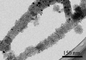
- FIG. 2 is a transmission electron microscope (TEM) photograph of the fibrous carbon nanohorn aggregate according to the present invention.
- FIG. 3 is a TEM photograph of spherical carbon nanohorn aggregates produced together with fibrous carbon nanohorn aggregates by the method of the present invention.
- Each single-layer carbon nanohorn constituting the fibrous carbon nanohorn aggregate of FIG. 2 according to the present embodiment is similar to the conventional single-layer carbon nanohorn constituting the spherical carbon nanohorn aggregate of FIG. The same.
- the fibrous carbon nanohorn aggregate is formed by connecting carbon nanohorn aggregates of seed type, bud type, dahlia type, petal dahlia type, and petal type (graphene sheet structure), that is, one type in the fibrous structure.
- a plurality of these carbon nanohorn aggregates are included.
- the catalyst metal exists inside or outside the fibrous carbon nanohorn aggregate or the spherical carbon nanohorn aggregate (non-transparent particles in FIG. 2). ).
- a fibrous carbon nanohorn aggregate is produced by the production method according to the present invention, a spherical carbon nanohorn aggregate is simultaneously generated.
- FIG. 4 is a scanning electron microscope (SEM) photograph of fibrous carbon nanohorn aggregates and spherical carbon nanohorn aggregates produced according to the present invention.
- the fibrous carbon nanohorn aggregate is fibrous and thus hardly re-aggregates, and has a structure excellent in dispersibility because single-layer carbon nanohorn aggregates are aggregated.
- the fibrous carbon nanohorn aggregate and the spherical carbon nanohorn aggregate may be referred to simply as a carbon nanohorn aggregate.
- the fibrous carbon nanohorn aggregate and the spherical carbon nanohorn aggregate can be separated using a centrifugal separation method, a difference in sedimentation speed after being dispersed in a solvent, gel permeation chromatography, or the like. .
- assembly it can remove by the separation by the centrifugation method, the difference in sedimentation speed, and size.
- the “fibrous” as used herein refers to a material that can maintain its shape to some extent even when the above separation operation is performed, and simply a plurality of spherical carbon nanohorn aggregates that appear to be fibrous at first glance. Different.
- the fibrous carbon nanohorn aggregate according to the present invention is not limited to the above structure as long as the single-layer carbon nanohorns are aggregated in a fibrous form. Fine holes can be formed in the single-walled carbon nanohorn of the carbon nanohorn aggregate, and the substance can be taken into the single-walled carbon nanohorn from the opening. Since the single-walled carbon nanohorn includes a structure other than a six-membered ring at the tip and side portions, the portion is preferentially oxidized and opened by oxidation treatment. Since the specific surface area is greatly improved by opening the holes, the use of a carbon nanohorn aggregate having a large specific surface area is advantageous for producing a planar structure.
- each single-walled carbon nanohorn obtained is approximately 1 nm to 5 nm, and the length is 30 nm to 100 nm.
- the fibrous carbon nanohorn aggregate can have a diameter of about 30 nm to 200 nm and a length of about 1 ⁇ m to 100 ⁇ m.
- the spherical carbon nanohorn aggregate has a diameter of about 30 nm to 200 nm and a substantially uniform size.
- the obtained carbon nanohorn aggregate is formed of a seed type, a bud type, a dahlia type, a petal-dahlia type, a petal type alone or in combination.
- the seed type has a shape with little or no square protrusions on the surface of the assembly
- the bud type has a shape with some angular protrusions on the surface of the assembly
- the dahlia type has the surface of the assembly.
- the petal type is a shape with petal-like protrusions on the surface of the aggregate.
- the petal structure is a graphene sheet structure having a width of 50 to 200 nm, a thickness of 0.34 to 10 nm, and 2 to 30 sheets.
- the petal-dahlia type is an intermediate structure between the dahlia type and the petal type.
- the spherical carbon nanohorn aggregates are generated in a mixed state separately from the fibrous carbon nanohorn aggregates.
- the form and particle size of the produced carbon nanohorn aggregate vary depending on the type and flow rate of the gas.
- the method for producing the fibrous carbon nanohorn aggregate is a catalyst-containing carbon target (referred to as a catalyst-containing carbon target), a nitrogen atmosphere, an inert atmosphere, while rotating the target in a container in which the catalyst-containing carbon target is placed.
- the target is heated by laser ablation under hydrogen, carbon dioxide, or a mixed atmosphere to evaporate the target.
- Fibrous carbon nanohorn aggregates and spherical carbon nanohorn aggregates are obtained in the process of cooling the evaporated carbon and the catalyst.
- a method using a carbon target containing a catalyst has been known in part as a method for producing carbon nanotubes
- conventional carbon nanohorn aggregates spherical carbon nanohorn aggregates
- a graphite target was used.
- an arc discharge method or a resistance heating method can be used in addition to the laser ablation method.
- the laser ablation method is more preferable from the viewpoint of continuous production at room temperature and atmospheric pressure.
- the laser ablation (LA) method applied in the present invention irradiates the target with a laser pulsed or continuously, and when the irradiation intensity exceeds a threshold value, the target converts energy, and as a result, the plume
- the generated product is deposited on a substrate provided downstream of the target, or is generated in a space in the apparatus and recovered in a recovery chamber.
- a CO 2 laser, a YAG laser, an excimer laser, a semiconductor laser, or the like can be used, and a CO 2 laser that can easily increase the output is most suitable.
- the CO 2 laser can use an output of 1 kW / cm 2 to 1000 kW / cm 2 and can be performed by continuous irradiation and pulse irradiation. Continuous irradiation is desirable for the production of carbon nanohorn aggregates.
- Laser light is condensed and irradiated by a ZnSe lens or the like. Moreover, it can synthesize
- the laser output is preferably 15 kW / cm 2 or more, and 30 to 300 kW / cm 2 is most effective.
- the laser output is 15 kW / cm 2 or more, the target is appropriately evaporated, and the production of the carbon nanohorn aggregate is facilitated.
- it is 300 kW / cm ⁇ 2 >, the increase in amorphous carbon can be suppressed.
- the pressure in the container (chamber) can be used at 13332.2 hPa (10000 Torr) or less, but the closer the pressure is to a vacuum, the more easily carbon nanotubes are produced, and the carbon nanohorn aggregates cannot be obtained.
- it is used at 666.61 hPa (500 Torr)-1266.56 hPa (950 Torr), more preferably near normal pressure (1013 hPa (1 atm ⁇ 760 Torr)) for mass synthesis and cost reduction.
- the irradiation area can also be controlled by the laser output and the degree of condensing by the lens, and 0.005 cm 2 to 1 cm 2 can be used.
- the catalyst can be used alone or as a mixture of Fe, Ni, and Co.
- the concentration of the catalyst can be appropriately selected, but is preferably 0.1% by mass to 10% by mass, more preferably 0.5% by mass to 5% by mass with respect to carbon.
- assembly becomes it sure that it is 0.1 mass% or more. Moreover, when it is 10 mass% or less, the increase in target cost can be suppressed.
- the inside of the container can be used at any temperature, preferably 0 to 100 ° C., and more preferably used at room temperature for mass synthesis and cost reduction.
- Nitrogen gas, inert gas, hydrogen gas, CO 2 gas, or the like is introduced into the container alone or in a mixture to achieve the above atmosphere. From the viewpoint of cost, nitrogen gas and Ar gas are preferable. These gases circulate in the reaction vessel, and the produced substances can be recovered by the gas flow. Moreover, it is good also as a closed atmosphere with the introduced gas. An arbitrary amount can be used as the atmospheric gas flow rate, but a range of 0.5 L / min to 100 L / min is preferable. In the process of evaporating the target, the gas flow rate is controlled to be constant. The gas flow rate can be made constant by combining the supply gas flow rate and the exhaust gas flow rate.
- part of the carbon skeleton may be substituted with a catalytic metal element, a nitrogen atom, or the like.
- the carbon nanohorn aggregate When fine holes are formed in the carbon nanohorn aggregate (opening), it can be performed by oxidation treatment. By this oxidation treatment, surface functional groups containing oxygen are formed in the pores.
- a gas phase process and a liquid phase process can be used.
- heat treatment is performed in an atmosphere gas containing oxygen such as air, oxygen, carbon dioxide, or the like. Among these, air is suitable from the viewpoint of cost.
- the temperature can be in the range of 300 to 650 ° C., and 400 to 550 ° C. is more suitable. Above 300 ° C, there is no concern that carbon will not burn and cannot be opened. In addition, at 650 ° C. or lower, the entire carbon nanohorn aggregate can be prevented from burning.
- a liquid phase process it is performed in a liquid containing an oxidizing substance such as nitric acid, sulfuric acid, and hydrogen peroxide.
- an oxidizing substance such as nitric acid, it can be used in a temperature range from room temperature to 120 ° C. If it is 120 degrees C or less, an oxidizing power will not become high too much and it will not oxidize more than necessary.
- hydrogen peroxide it can be used in the temperature range of room temperature to 100 ° C., more preferably 40 ° C. or higher. In the temperature range of 40 to 100 ° C., the oxidizing power acts efficiently, and the holes can be formed efficiently. In the liquid phase process, it is more effective to use light irradiation together.
- the catalytic metal contained in the formation of the carbon nanohorn aggregate can be removed before the oxidation treatment.
- the catalytic metal can be removed because it dissolves in nitric acid, sulfuric acid and hydrochloric acid. From the viewpoint of ease of use, hydrochloric acid is suitable.
- the temperature at which the catalyst is dissolved can be appropriately selected. However, when the catalyst is sufficiently removed, it is desirable to carry out the heating to 70 ° C. or higher. When nitric acid or sulfuric acid is used, catalyst removal and pore formation can be performed simultaneously or sequentially.
- the catalyst since the catalyst may be covered with a carbon film when the carbon nanohorn aggregate is formed, it is desirable to perform a pretreatment to remove the carbon film.
- the pretreatment is desirably performed at about 250 to 450 ° C. in air.
- Some openings may be formed as described above at 300 ° C. or higher. However, in the present invention, the formation of openings is not a problem because it is a preferred embodiment depending on the application.
- the obtained carbon nanohorn aggregate can be improved in crystallinity by heat treatment in a non-oxidizing atmosphere such as inert gas, hydrogen, or vacuum.
- the heat treatment temperature can be 800 to 2000 ° C., but preferably 1000 to 1500 ° C.
- a surface functional group containing oxygen is formed in the opening, but it can be removed by heat treatment.
- the heat treatment temperature can be 150 to 2000 ° C. In order to remove surface functional groups such as carboxyl groups and hydroxyl groups, 150 ° C. to 600 ° C. is desirable.
- the carbonyl group etc. which are surface functional groups 600 degreeC or more is desirable.
- the surface functional group can be removed by reduction in a gas or liquid atmosphere. Hydrogen can be used for the reduction in the gas atmosphere, and it can be combined with the improvement of the crystallinity. Hydrazine or the like can be used in a liquid atmosphere.
- the mixture of the fibrous carbon nanohorn aggregate and the spherical carbon nanohorn aggregate (hereinafter also referred to as the carbon nanohorn aggregate mixture) can be used as it is, or the fibrous carbon nanohorn aggregate can be isolated or the pores can be formed. After formation, the film can be thinned and used as a planar structure.
- the planar structure according to the present invention may contain at least one mixed material of carbon, carbon compound, metal, metalloid, and oxide.
- the carbon for example, one or more selected from carbon black such as graphite, graphitizable carbon, non-graphitizable carbon, activated carbon, acetylene black and ketjen black, carbon nanotube, and graphene can be used.
- the carbon compound include silicon carbide, nitrogen carbide, silicon carbonitride, and the like.
- the metal one or more selected from iron, nickel, manganese, copper, silver, gold, platinum, aluminum, titanium, zinc, and chromium can be used.
- the metalloid at least one of boron and silicon can be used.
- the oxide one or more of the above metal or metalloid oxides can be used.
- a carbon nanohorn aggregate mixture and, if necessary, the above mixture are dispersed in a suitable solvent such as alcohol, and the obtained dispersion is applied onto a substrate and dried. It is obtained by doing.
- the carbon nanohorn aggregate mixture can be made into a thin film without a binder, but a binder may be used.
- a binder various resin materials can be used, but at least one selected from polyvinylidene fluoride, acrylic resin, styrene butadiene rubber, imide resin, imidoamide resin, polytetrafluoroethylene resin, and polyamide resin is preferable.
- the planar structure containing the fibrous carbon nanohorn aggregate can be used for various applications that take advantage of the characteristics of the carbon nanohorn aggregate.
- the carbon nanohorn aggregate contributes to improvement in conductivity when the fibrous structure is thinned as a conductive path. It also excels in catalytic activity, adsorption / absorption, and thermal conductivity. For example, it can be used for electrode materials of lithium ion batteries, fuel cells, capacitors, electrochemical actuators, air cells, and solar cells. It can also be used for electromagnetic shields, heat conductive sheets, heat dissipation sheets, protective sheets, filters, and absorbent materials.
- Example 1 Fibrous carbon nanohorn aggregates and spherical carbon nanohorn aggregates were prepared by irradiating a carbon target containing about 5% by mass of iron with a CO 2 laser in a nitrogen atmosphere (sample 1). Details of the experiment are shown below. A carbon target containing iron was rotated at 2 rpm. The energy density of the CO 2 laser was continuously irradiated at 150 kW / cm 2 , and the chamber temperature was room temperature. In the chamber, the gas flow rate was adjusted to 10 L / min. The pressure was controlled at 933.254 to 1266.559 hPa (700 to 950 Torr). In addition, as a comparative sample, a laser ablated sample was also produced under a nitrogen atmosphere using a carbon target not containing a catalyst under the same conditions (Sample 2).
- FIG. 4 is an SEM photograph of Sample 1. Fibrous and spherical materials are observed. The fibrous substance has a diameter of about 30 to 100 nm and a length of several ⁇ m to several tens of ⁇ m. Most of the spherical substances have a substantially uniform size within a diameter range of about 30 to 200 nm. 2 and 3 are TEM photographs of the product. From the observation results of the fibrous substance, it was found that single-walled carbon nanohorns having a diameter of about 1-5 nm and a length of about 40-50 nm are gathered in a fibrous form.
- Sample 1 (1 mg) was mixed with 30 ml of ethanol and subjected to ultrasonic dispersion for 15 minutes to prepare a dispersion. The obtained dispersion was dropped on a silicon substrate and dried. It repeated until the film thickness became 1 micrometer. The laser microscope image of the obtained thin film is shown in FIG. As a result, it was confirmed that a uniform film was formed.
- FIG. 6 shows a thin film produced from Sample 2 by the same method. As a result, it was confirmed that the surface formed unevenness and cracks. Sample 1 is considered to maintain a uniform state because the fibrous structure prevents reaggregation of spherical aggregates and the fibrous structure is entangled when ethanol is dried.
- a thin film using Sample 3 (activated carbon (YP50F: manufactured by Kuraray)) and Sample 4 (1: 1 mixture of Sample 3 and Sample 1) was prepared in the same manner as Sample 1.
- the sheet resistivity of the thin film using Samples 1 to 4 was measured.
- four prober tips were arranged in one row, current I was passed through the outer electrode pair, and voltage V between the inner electrode pair was measured.
- the obtained sheet resistivity was 1 ⁇ cm, 15 ⁇ cm, 25 ⁇ cm, and 10 ⁇ cm for Samples 1, 2, 3, and 4, respectively. From this result, it was found that Sample 1 having a uniform thin film and excellent conductivity had the lowest resistivity. Samples 2 and 3 where it is difficult to form a uniform thin film have high resistivity values.
- the sample 4 added the sample 1 and the thin film of the sample 3 was equalized, and the resistivity decreased.
- Example 2 Electrode material for electric double layer capacitor
- Samples 1 and 2 were mixed at 80% by mass and PVDF at 20% by mass, respectively, and N-methyl-2-pyrrolidinone was further mixed and stirred sufficiently to prepare a paste.
- the obtained paste was applied to an Al current collector with a thickness of about 100 ⁇ m.
- the electrode body was pressure-molded with the roll press. Furthermore, this electrode body was vacuum-dried at 60 ° C. for 24 hours, and punched into a circle having a diameter of 12 mm to obtain an electrode plate for an electric double layer capacitor (positive electrode, negative electrode).
- a coin cell was prepared (sample) A, sample B).
- Samples 1 and 2 were heated in air at 450 ° C. and 500 ° C., respectively, to prepare samples 5 and 6 that were oxidized, and coin cells were prepared (sample C and sample D), respectively.
- Samples 5 and 6 single-walled carbon nanohorns were opened, and the inside could be used, and the specific surface area was approximately four times as large.
- Coin cells were set in a charge / discharge tester, and charged and discharged at a constant current from a voltage of 0 V to 2.5 V.
- rate characteristics rapid charge / discharge characteristics
- the discharge characteristics were evaluated at 0.1, 1, 10 A / g in the same voltage range as above (Table 1). It was found that the capacity at the low rate is the largest for sample C and depends on the specific surface area.
- Sample A and Sample C had a small capacity decrease due to an increase in discharge rate. This is because the electrode film containing the fibrous carbon nanohorn aggregate is produced uniformly, thereby reducing the internal resistance of the electrode.
- the planar structure of the present invention can be used for electrode materials for lithium ion batteries, fuel cells, capacitors, electrochemical actuators, air cells, and solar cells. It can also be used for electromagnetic shields, heat conductive sheets, heat dissipation sheets, protective sheets, filters, and absorbent materials.
- Embodiments of the present invention include configurations described in the following supplementary notes, but are not limited to these configurations.
- Appendix 1 A planar structure comprising a fibrous carbon nanohorn aggregate in which a plurality of single-layer carbon nanohorns are aggregated in a fibrous form.
- Appendix 2 The planar structure according to appendix 1, wherein the fibrous carbon nanohorn aggregate has a diameter of 30 nm to 200 nm and a length of 1 ⁇ m to 100 ⁇ m.
- Appendix 3) The planar structure according to appendix 1 or 2, wherein each single-walled carbon nanohorn has a diameter of 1 nm to 5 nm, a length of 30 nm to 100 nm, and a tip having a horn shape.
- the fibrous carbon nanohorn aggregate is any one of appendices 1 to 3, wherein at least one carbon nanohorn aggregate of a seed type, a dahlia type, a bud type, a petal dahlia type, and a petal type is connected in a fibrous form
- the planar structure described in 1. (Appendix 5) Furthermore, it includes at least one kind of spherical carbon nanohorn aggregate of seed type, bud type, dahlia type, petal dahlia type, petal type, which does not constitute the fibrous carbon nanohorn aggregate.
- the planar structure according to any one of the above. (Appendix 6) 6.
- Appendix 7 The planar structure according to any one of supplementary notes 1 to 6, further comprising at least one of carbon, a carbon compound, a metal, a metalloid, and an oxide.
- the carbon is at least one selected from graphite, graphitizable carbon, non-graphitizable carbon, activated carbon, carbon black, carbon nanotube, graphene, and the metal is iron, nickel, manganese, copper, silver, One or more selected from gold, platinum, aluminum, titanium, zinc and chromium, the semimetal is at least one of boron and silicon, and the oxide is one or more of the above metals and metalloid oxides
- Appendix 11 11.
- Appendix 12 11.
- Appendix 13 11.
- Appendix 14 14.
- Appendix 15 11.
- Appendix 16 11. The planar structure according to any one of appendices 1 to 10, which is an electrode material for an air battery.
- Appendix 17 11. The planar structure according to any one of appendices 1 to 10, which is an electrode material for a solar cell.
- Appendix 18 11. The planar structure according to any one of appendices 1 to 10, which is an electromagnetic shield.
- Appendix 19 11. The planar structure according to any one of appendices 1 to 10, which is a heat conductive sheet.
- Appendix 20 11. The planar structure according to any one of appendices 1 to 10, which is a heat dissipation sheet.
- (Appendix 24) The planar structure according to appendix 22, wherein the filter is a dust collection filter.
- Appendix 27 The planar structure according to appendix 26, wherein the absorbent material absorbs gas or liquid.
- Appendix 28 Item 27. The planar structure according to appendix 26, which absorbs a substance having a lawn property.
Landscapes
- Chemical & Material Sciences (AREA)
- Engineering & Computer Science (AREA)
- Materials Engineering (AREA)
- Nanotechnology (AREA)
- Chemical Kinetics & Catalysis (AREA)
- General Chemical & Material Sciences (AREA)
- Power Engineering (AREA)
- Electrochemistry (AREA)
- Organic Chemistry (AREA)
- Inorganic Chemistry (AREA)
- Microelectronics & Electronic Packaging (AREA)
- Manufacturing & Machinery (AREA)
- Condensed Matter Physics & Semiconductors (AREA)
- Electromagnetism (AREA)
- General Physics & Mathematics (AREA)
- Computer Hardware Design (AREA)
- Physics & Mathematics (AREA)
- Textile Engineering (AREA)
- Crystallography & Structural Chemistry (AREA)
- Carbon And Carbon Compounds (AREA)
- Inert Electrodes (AREA)
Abstract
L'invention utilise une structure plate (1) caractérisée en ce qu'elle comprend des agrégats de nanocornets carbonés fibreux (2) dans lesquels une pluralité de nanocornets carbonés simple paroi sont agrégés en fibres, en particulier une structure plate (1) dans laquelle des agrégats de nanocornets carbonés sphériques (3) sont mélangés. Une structure plate de cette description comprenant des agrégats de nanocornets carbonés fibreux peut être utilisée dans un matériau d'électrode pour pile au lithium-ion, pile à combustible, condensateur, actionneur électrochimique, pile à dépolarisation par l'air, cellule solaire ou similaire. La structure plate peut également être utilisée dans un blindage électromagnétique, une feuille conductrice thermique, une feuille de dissipation thermique, une feuille de protection, un filtre ou un matériau absorbant.
Priority Applications (2)
| Application Number | Priority Date | Filing Date | Title |
|---|---|---|---|
| JP2018505791A JP7260141B2 (ja) | 2016-03-16 | 2017-02-28 | 繊維状カーボンナノホーン集合体を含んだ平面構造体 |
| US16/085,309 US10971734B2 (en) | 2016-03-16 | 2017-02-28 | Planar structural body containing fibrous carbon nanohorn aggregate |
Applications Claiming Priority (2)
| Application Number | Priority Date | Filing Date | Title |
|---|---|---|---|
| JP2016-052229 | 2016-03-16 | ||
| JP2016052229 | 2016-03-16 |
Publications (1)
| Publication Number | Publication Date |
|---|---|
| WO2017159351A1 true WO2017159351A1 (fr) | 2017-09-21 |
Family
ID=59852192
Family Applications (1)
| Application Number | Title | Priority Date | Filing Date |
|---|---|---|---|
| PCT/JP2017/007794 WO2017159351A1 (fr) | 2016-03-16 | 2017-02-28 | Structure plate comprenant un agrégat de nanocornets carbonés fibreux |
Country Status (3)
| Country | Link |
|---|---|
| US (1) | US10971734B2 (fr) |
| JP (1) | JP7260141B2 (fr) |
| WO (1) | WO2017159351A1 (fr) |
Cited By (12)
| Publication number | Priority date | Publication date | Assignee | Title |
|---|---|---|---|---|
| WO2018037881A1 (fr) * | 2016-08-25 | 2018-03-01 | 日本電気株式会社 | Électrode flexible et élément de capteur |
| CN108011082A (zh) * | 2017-11-20 | 2018-05-08 | 郑州天舜电子技术有限公司 | 一种锂离子电池负极材料及其制备方法 |
| WO2019116893A1 (fr) * | 2017-12-13 | 2019-06-20 | 日本電気株式会社 | Méthode de raccourcissement d'agrégat de nanocornet de carbone fibreux et agrégat de nanocornet de carbone fibreux raccourci |
| WO2019229841A1 (fr) * | 2018-05-29 | 2019-12-05 | 日本電気株式会社 | Méthode de production continue d'agrégat de nanocornets de carbone fibreux |
| JP2020021577A (ja) * | 2018-07-31 | 2020-02-06 | 株式会社グラヴィトン | 固体高分子形燃料電池及び電極製造方法 |
| WO2020153296A1 (fr) * | 2019-01-21 | 2020-07-30 | 日本電気株式会社 | Corps moulé par étirage |
| WO2020158674A1 (fr) * | 2019-01-28 | 2020-08-06 | 日本電気株式会社 | Agrégat de matériau nanocarbone et catalyseur destiné à une réaction électrochimique contenant ce dernier |
| WO2020173070A1 (fr) * | 2019-02-27 | 2020-09-03 | 上海利物盛企业集团有限公司 | Nanomatériau tridimensionnel auto-assemblé de conservation superhydrophobe et son procédé de préparation |
| CN112279248A (zh) * | 2020-10-21 | 2021-01-29 | 中国科学院广州能源研究所 | 一种利用太阳能供热的活性炭制备系统 |
| EP3690906A4 (fr) * | 2017-09-27 | 2021-07-07 | National Institute for Materials Science | Électrode contenant du graphène, son procédé de fabrication, et dispositif accumulateur d'électricité l'utilisant |
| US20230378650A1 (en) * | 2021-02-24 | 2023-11-23 | Bluehalo, Llc | System and method for a digitally beamformed phased array feed |
| US11981568B2 (en) | 2019-01-29 | 2024-05-14 | Nec Corporation | Member for continuous production of carbon nanobrush, and method for continuous production of carbon nanobrush |
Citations (9)
| Publication number | Priority date | Publication date | Assignee | Title |
|---|---|---|---|---|
| JP2005039295A (ja) * | 2004-10-21 | 2005-02-10 | Japan Science & Technology Agency | 分極性電極及びそれを用いた電気二重層コンデンサ |
| JP2008248457A (ja) * | 2007-03-30 | 2008-10-16 | Nano Carbon Technologies Kk | 炭素繊維複合体および炭素繊維複合体の製造方法 |
| WO2008139963A1 (fr) * | 2007-05-07 | 2008-11-20 | Hokkaido University | Masse d'agregat de fibres de carbone fine, destinée à être redispersée et procédé de production associé |
| WO2013183187A1 (fr) * | 2012-06-06 | 2013-12-12 | 日本電気株式会社 | Matériau actif d'électrode négative et son processus de fabrication associé |
| JP2014012921A (ja) * | 2007-10-23 | 2014-01-23 | Tokushu Tokai Seishi Co Ltd | シート状物及びその製造方法 |
| WO2015146984A1 (fr) * | 2014-03-27 | 2015-10-01 | 日本バイリーン株式会社 | Corps poreux électroconducteur, pile à combustible à polymère solide, et procédé de fabrication de corps poreux électroconducteur |
| WO2015186742A1 (fr) * | 2014-06-06 | 2015-12-10 | 日本電気株式会社 | Composite à base de nanocarbone et son procédé de production |
| WO2016147909A1 (fr) * | 2015-03-16 | 2016-09-22 | 日本電気株式会社 | Agrégats de nanocornets de carbone fibreux et leur procédé de production |
| WO2016208170A1 (fr) * | 2015-06-22 | 2016-12-29 | 日本電気株式会社 | Matériau composite de nanocarbone et son procédé de production |
Family Cites Families (19)
| Publication number | Priority date | Publication date | Assignee | Title |
|---|---|---|---|---|
| JP4234812B2 (ja) | 1998-07-25 | 2009-03-04 | 独立行政法人科学技術振興機構 | 単層カーボンナノホーン構造体とその製造方法 |
| EP1364704A4 (fr) | 2001-01-29 | 2007-06-06 | Japan Science & Tech Agency | Adsorbant a base de nanotubes de carbone et methode de production de l'adsorbant |
| JP3479889B2 (ja) | 2001-07-13 | 2003-12-15 | 科学技術振興事業団 | カーボンナノホーンとその製造方法 |
| JP2003077385A (ja) * | 2001-09-04 | 2003-03-14 | Japan Science & Technology Corp | 電界電子放出素子 |
| JP3798300B2 (ja) | 2001-11-13 | 2006-07-19 | 東邦瓦斯株式会社 | 水素の製造方法 |
| JP2003313571A (ja) | 2002-04-19 | 2003-11-06 | Japan Science & Technology Corp | カーボンナノホーン固体潤滑剤 |
| JP2004016976A (ja) | 2002-06-18 | 2004-01-22 | Japan Science & Technology Corp | セルフロッキングカーボン吸着体 |
| JP4873870B2 (ja) | 2004-05-07 | 2012-02-08 | 独立行政法人科学技術振興機構 | 薬物カーボンナノホーン複合体からなるalp発現誘導剤および抗ガン剤とその製造方法 |
| JP5130544B2 (ja) * | 2006-07-07 | 2013-01-30 | 日本電気株式会社 | ポリアミンプラグを持つ物質内包カーボンナノホーン複合体、およびその製造方法 |
| JP5384917B2 (ja) | 2008-11-20 | 2014-01-08 | オートモーティブエナジーサプライ株式会社 | リチウムイオン電池 |
| KR101499602B1 (ko) * | 2009-05-26 | 2015-03-09 | 가부시키가이샤 인큐베이션 얼라이언스 | 탄소 재료 및 그 제조 방법 |
| KR101470524B1 (ko) * | 2009-06-30 | 2014-12-08 | 한화케미칼 주식회사 | 혼화성이 증대된 복합탄소소재 및 이의 연속적인 제조 방법 |
| JP6068334B2 (ja) * | 2011-04-15 | 2017-01-25 | 株式会社環境・エネルギーナノ技術研究所 | カーボンナノ材料製造装置及びその利用 |
| TWI483896B (zh) * | 2012-08-22 | 2015-05-11 | Univ Nat Defense | 螺旋奈米碳材製備方法、其螺旋奈米碳材層基板及其螺旋奈米碳材 |
| CN105247674B (zh) | 2013-06-03 | 2018-04-13 | 富士通株式会社 | 散热结构体及其制造方法以及电子装置 |
| CN104047157A (zh) | 2014-05-26 | 2014-09-17 | 昆明纳太能源科技有限公司 | 基于光热效应制备碳纳米复合材料的方法 |
| JP6922893B2 (ja) * | 2016-03-16 | 2021-08-18 | 日本電気株式会社 | 吸着材 |
| JP7176411B2 (ja) * | 2016-08-25 | 2022-11-22 | 日本電気株式会社 | フレキシブル電極及びセンサー素子 |
| EP3509408B1 (fr) * | 2016-09-05 | 2021-11-10 | Nec Corporation | Matériau absorbant les ondes électromagnétiques |
-
2017
- 2017-02-28 WO PCT/JP2017/007794 patent/WO2017159351A1/fr active Application Filing
- 2017-02-28 JP JP2018505791A patent/JP7260141B2/ja active Active
- 2017-02-28 US US16/085,309 patent/US10971734B2/en active Active
Patent Citations (9)
| Publication number | Priority date | Publication date | Assignee | Title |
|---|---|---|---|---|
| JP2005039295A (ja) * | 2004-10-21 | 2005-02-10 | Japan Science & Technology Agency | 分極性電極及びそれを用いた電気二重層コンデンサ |
| JP2008248457A (ja) * | 2007-03-30 | 2008-10-16 | Nano Carbon Technologies Kk | 炭素繊維複合体および炭素繊維複合体の製造方法 |
| WO2008139963A1 (fr) * | 2007-05-07 | 2008-11-20 | Hokkaido University | Masse d'agregat de fibres de carbone fine, destinée à être redispersée et procédé de production associé |
| JP2014012921A (ja) * | 2007-10-23 | 2014-01-23 | Tokushu Tokai Seishi Co Ltd | シート状物及びその製造方法 |
| WO2013183187A1 (fr) * | 2012-06-06 | 2013-12-12 | 日本電気株式会社 | Matériau actif d'électrode négative et son processus de fabrication associé |
| WO2015146984A1 (fr) * | 2014-03-27 | 2015-10-01 | 日本バイリーン株式会社 | Corps poreux électroconducteur, pile à combustible à polymère solide, et procédé de fabrication de corps poreux électroconducteur |
| WO2015186742A1 (fr) * | 2014-06-06 | 2015-12-10 | 日本電気株式会社 | Composite à base de nanocarbone et son procédé de production |
| WO2016147909A1 (fr) * | 2015-03-16 | 2016-09-22 | 日本電気株式会社 | Agrégats de nanocornets de carbone fibreux et leur procédé de production |
| WO2016208170A1 (fr) * | 2015-06-22 | 2016-12-29 | 日本電気株式会社 | Matériau composite de nanocarbone et son procédé de production |
Cited By (26)
| Publication number | Priority date | Publication date | Assignee | Title |
|---|---|---|---|---|
| US10937598B2 (en) | 2016-08-25 | 2021-03-02 | Nec Corporation | Flexible electrode and sensor element |
| WO2018037881A1 (fr) * | 2016-08-25 | 2018-03-01 | 日本電気株式会社 | Électrode flexible et élément de capteur |
| EP3690906A4 (fr) * | 2017-09-27 | 2021-07-07 | National Institute for Materials Science | Électrode contenant du graphène, son procédé de fabrication, et dispositif accumulateur d'électricité l'utilisant |
| CN108011082B (zh) * | 2017-11-20 | 2020-02-11 | 萝北泰东德新材料科技有限公司 | 一种锂离子电池负极材料及其制备方法 |
| CN108011082A (zh) * | 2017-11-20 | 2018-05-08 | 郑州天舜电子技术有限公司 | 一种锂离子电池负极材料及其制备方法 |
| JPWO2019116893A1 (ja) * | 2017-12-13 | 2020-12-24 | 日本電気株式会社 | 繊維状のカーボンナノホーン集合体の短尺化方法及び短尺化された繊維状のカーボンナノホーン集合体 |
| US11498837B2 (en) | 2017-12-13 | 2022-11-15 | Nec Corporation | Method for shortening fibrous carbon nanohorn aggregate and shortened fibrous carbon nanohorn aggregate |
| WO2019116893A1 (fr) * | 2017-12-13 | 2019-06-20 | 日本電気株式会社 | Méthode de raccourcissement d'agrégat de nanocornet de carbone fibreux et agrégat de nanocornet de carbone fibreux raccourci |
| US11511998B2 (en) | 2018-05-29 | 2022-11-29 | Nec Corporation | Continuous production method of fibrous carbon nanohorn aggregate |
| JP7099522B2 (ja) | 2018-05-29 | 2022-07-12 | 日本電気株式会社 | 繊維状カーボンナノホーン集合体の連続製造方法 |
| WO2019229841A1 (fr) * | 2018-05-29 | 2019-12-05 | 日本電気株式会社 | Méthode de production continue d'agrégat de nanocornets de carbone fibreux |
| JPWO2019229841A1 (ja) * | 2018-05-29 | 2021-06-03 | 日本電気株式会社 | 繊維状カーボンナノホーン集合体の連続製造方法 |
| JP2020021577A (ja) * | 2018-07-31 | 2020-02-06 | 株式会社グラヴィトン | 固体高分子形燃料電池及び電極製造方法 |
| JP7281158B2 (ja) | 2018-07-31 | 2023-05-25 | グローバル・リンク株式会社 | 固体高分子形燃料電池及び電極製造方法 |
| WO2020153296A1 (fr) * | 2019-01-21 | 2020-07-30 | 日本電気株式会社 | Corps moulé par étirage |
| JPWO2020153296A1 (ja) * | 2019-01-21 | 2021-12-09 | 日本電気株式会社 | 延伸成形体 |
| JP7107394B2 (ja) | 2019-01-21 | 2022-07-27 | 日本電気株式会社 | 延伸成形体 |
| JPWO2020158674A1 (ja) * | 2019-01-28 | 2021-12-02 | 日本電気株式会社 | ナノカーボン材料集合体およびこれを含む電気化学反応用触媒 |
| JP7238909B2 (ja) | 2019-01-28 | 2023-03-14 | 日本電気株式会社 | ナノカーボン材料集合体およびこれを含む電気化学反応用触媒 |
| WO2020158674A1 (fr) * | 2019-01-28 | 2020-08-06 | 日本電気株式会社 | Agrégat de matériau nanocarbone et catalyseur destiné à une réaction électrochimique contenant ce dernier |
| US11981568B2 (en) | 2019-01-29 | 2024-05-14 | Nec Corporation | Member for continuous production of carbon nanobrush, and method for continuous production of carbon nanobrush |
| JP2022512339A (ja) * | 2019-02-27 | 2022-02-03 | 上海利物盛企業集団有限公司 | 超疎水性防腐自己組織化三次元ナノ材料およびその製造方法 |
| WO2020173070A1 (fr) * | 2019-02-27 | 2020-09-03 | 上海利物盛企业集团有限公司 | Nanomatériau tridimensionnel auto-assemblé de conservation superhydrophobe et son procédé de préparation |
| JP7201813B2 (ja) | 2019-02-27 | 2023-01-10 | 上海利物盛企業集団有限公司 | 超疎水性防腐自己組織化三次元ナノ材料およびその製造方法 |
| CN112279248A (zh) * | 2020-10-21 | 2021-01-29 | 中国科学院广州能源研究所 | 一种利用太阳能供热的活性炭制备系统 |
| US20230378650A1 (en) * | 2021-02-24 | 2023-11-23 | Bluehalo, Llc | System and method for a digitally beamformed phased array feed |
Also Published As
| Publication number | Publication date |
|---|---|
| JPWO2017159351A1 (ja) | 2019-01-17 |
| US20190081330A1 (en) | 2019-03-14 |
| US10971734B2 (en) | 2021-04-06 |
| JP7260141B2 (ja) | 2023-04-18 |
Similar Documents
| Publication | Publication Date | Title |
|---|---|---|
| JP7260141B2 (ja) | 繊維状カーボンナノホーン集合体を含んだ平面構造体 | |
| JP6686826B2 (ja) | 繊維状のカーボンナノホーン集合体及びその製造方法 | |
| TWI752933B (zh) | 藉由催化劑溶液之奈米碳管混合材料的簡易製備 | |
| Cao et al. | Metal etching method for preparing porous graphene as high performance anode material for lithium-ion batteries | |
| JP7198331B2 (ja) | 電極構造体 | |
| WO2014129597A1 (fr) | Matière de carbone en vue d'une utilisation comme support de catalyseur | |
| Zhang et al. | Thermal reduction of graphene oxide mixed with hard carbon and their high performance as lithium ion battery anode | |
| JP6119492B2 (ja) | カーボンナノホーン集合体、これを用いた電極材料及びその製造方法 | |
| JP2009208061A (ja) | 炭素触媒及びこの炭素触媒を含むスラリー、炭素触媒の製造方法、ならびに、炭素触媒を用いた燃料電池、蓄電装置及び環境触媒 | |
| JP2012094509A (ja) | 複合電極材及びその製造方法、並びに金属空気電池用負極及び金属空気電池 | |
| CN110391398B (zh) | 黑磷/还原氧化石墨烯复合电极及其制备方法以及包括该复合电极的柔性锂离子电池 | |
| Sedira et al. | Hydrothermal synthesis of spherical carbon nanoparticles (CNPs) for supercapacitor electrodes uses | |
| JP6922893B2 (ja) | 吸着材 | |
| JP2011063458A (ja) | カーボンナノチューブ粉体、電極用導電助剤及びそれを用いた電極並びに該電極を用いた蓄電デバイス | |
| KR20140075275A (ko) | 독립형 탄소나노튜브/금속 산화물 입자 복합체 필름 및 그 제조방법 | |
| Rudakov et al. | Synthesis of hollow carbon nanoshells and their application for supercapacitors | |
| Na et al. | Electrochemical performance of Si-multiwall carbon nanotube nanocomposite anode synthesized by thermal plasma | |
| JP6989709B2 (ja) | 電極構造体、その製造方法、およびこれを含む電気化学素子 | |
| WO2020066010A1 (fr) | Matériau carboné destiné à un support de catalyseur de pile à combustible à polymère solide et son procédé de fabrication | |
| CN107230778B (zh) | 用于可控地合成碳基电池电极材料的方法 | |
| CN117480119A (zh) | 作为储能装置中的电极材料的石墨烯纳米带 | |
| JP5776150B2 (ja) | カーボンナノホーン集合体及びその製造方法並びにカーボンナノホーンを備える電池及びその製造方法 | |
| KR101508480B1 (ko) | 리튬 이차전지용 전극 및 이의 제조방법 | |
| Marka et al. | Solid-state processed novel germanium/reduced graphene oxide composite: Its detailed characterization, formation mechanism and excellent Li storage ability | |
| JP2012059838A (ja) | 電気二重層キャパシタ用分極性電極、電気二重層キャパシタ及びリチウムイオンキャパシタ |
Legal Events
| Date | Code | Title | Description |
|---|---|---|---|
| WWE | Wipo information: entry into national phase |
Ref document number: 2018505791 Country of ref document: JP |
|
| NENP | Non-entry into the national phase |
Ref country code: DE |
|
| 121 | Ep: the epo has been informed by wipo that ep was designated in this application |
Ref document number: 17766354 Country of ref document: EP Kind code of ref document: A1 |
|
| 122 | Ep: pct application non-entry in european phase |
Ref document number: 17766354 Country of ref document: EP Kind code of ref document: A1 |