WO2017159351A1 - Flat structure including fibrous carbon nanohorn aggregate - Google Patents
Flat structure including fibrous carbon nanohorn aggregate Download PDFInfo
- Publication number
- WO2017159351A1 WO2017159351A1 PCT/JP2017/007794 JP2017007794W WO2017159351A1 WO 2017159351 A1 WO2017159351 A1 WO 2017159351A1 JP 2017007794 W JP2017007794 W JP 2017007794W WO 2017159351 A1 WO2017159351 A1 WO 2017159351A1
- Authority
- WO
- WIPO (PCT)
- Prior art keywords
- carbon nanohorn
- carbon
- planar structure
- fibrous
- type
- Prior art date
Links
- OKTJSMMVPCPJKN-UHFFFAOYSA-N Carbon Chemical compound [C] OKTJSMMVPCPJKN-UHFFFAOYSA-N 0.000 title claims abstract description 175
- 229910052799 carbon Inorganic materials 0.000 title claims abstract description 149
- 239000002116 nanohorn Substances 0.000 title claims abstract description 130
- VNWKTOKETHGBQD-UHFFFAOYSA-N methane Chemical compound C VNWKTOKETHGBQD-UHFFFAOYSA-N 0.000 claims abstract description 12
- 241000132500 Dahlia <angiosperm> Species 0.000 claims description 16
- 235000012040 Dahlia pinnata Nutrition 0.000 claims description 16
- 229910052751 metal Inorganic materials 0.000 claims description 15
- 239000002184 metal Substances 0.000 claims description 15
- XEEYBQQBJWHFJM-UHFFFAOYSA-N Iron Chemical compound [Fe] XEEYBQQBJWHFJM-UHFFFAOYSA-N 0.000 claims description 13
- 239000011230 binding agent Substances 0.000 claims description 11
- 229910052752 metalloid Inorganic materials 0.000 claims description 8
- 150000002738 metalloids Chemical class 0.000 claims description 8
- PXHVJJICTQNCMI-UHFFFAOYSA-N Nickel Chemical compound [Ni] PXHVJJICTQNCMI-UHFFFAOYSA-N 0.000 claims description 7
- 229910021393 carbon nanotube Inorganic materials 0.000 claims description 7
- 239000002041 carbon nanotube Substances 0.000 claims description 7
- 229910052742 iron Inorganic materials 0.000 claims description 7
- BASFCYQUMIYNBI-UHFFFAOYSA-N platinum Chemical compound [Pt] BASFCYQUMIYNBI-UHFFFAOYSA-N 0.000 claims description 6
- 239000002356 single layer Substances 0.000 claims description 6
- 150000001722 carbon compounds Chemical class 0.000 claims description 5
- 229910021389 graphene Inorganic materials 0.000 claims description 5
- 229910052710 silicon Inorganic materials 0.000 claims description 5
- 239000010703 silicon Substances 0.000 claims description 5
- 229910002804 graphite Inorganic materials 0.000 claims description 4
- 239000010439 graphite Substances 0.000 claims description 4
- 229910052759 nickel Inorganic materials 0.000 claims description 4
- ZOXJGFHDIHLPTG-UHFFFAOYSA-N Boron Chemical compound [B] ZOXJGFHDIHLPTG-UHFFFAOYSA-N 0.000 claims description 3
- VYZAMTAEIAYCRO-UHFFFAOYSA-N Chromium Chemical compound [Cr] VYZAMTAEIAYCRO-UHFFFAOYSA-N 0.000 claims description 3
- RYGMFSIKBFXOCR-UHFFFAOYSA-N Copper Chemical compound [Cu] RYGMFSIKBFXOCR-UHFFFAOYSA-N 0.000 claims description 3
- RTAQQCXQSZGOHL-UHFFFAOYSA-N Titanium Chemical compound [Ti] RTAQQCXQSZGOHL-UHFFFAOYSA-N 0.000 claims description 3
- HCHKCACWOHOZIP-UHFFFAOYSA-N Zinc Chemical compound [Zn] HCHKCACWOHOZIP-UHFFFAOYSA-N 0.000 claims description 3
- 229910052782 aluminium Inorganic materials 0.000 claims description 3
- XAGFODPZIPBFFR-UHFFFAOYSA-N aluminium Chemical compound [Al] XAGFODPZIPBFFR-UHFFFAOYSA-N 0.000 claims description 3
- 229910052796 boron Inorganic materials 0.000 claims description 3
- 239000006229 carbon black Substances 0.000 claims description 3
- 229910052804 chromium Inorganic materials 0.000 claims description 3
- 239000011651 chromium Substances 0.000 claims description 3
- 229910052802 copper Inorganic materials 0.000 claims description 3
- 239000010949 copper Substances 0.000 claims description 3
- PCHJSUWPFVWCPO-UHFFFAOYSA-N gold Chemical compound [Au] PCHJSUWPFVWCPO-UHFFFAOYSA-N 0.000 claims description 3
- 229910052737 gold Inorganic materials 0.000 claims description 3
- 239000010931 gold Substances 0.000 claims description 3
- 229910021469 graphitizable carbon Inorganic materials 0.000 claims description 3
- WPBNNNQJVZRUHP-UHFFFAOYSA-L manganese(2+);methyl n-[[2-(methoxycarbonylcarbamothioylamino)phenyl]carbamothioyl]carbamate;n-[2-(sulfidocarbothioylamino)ethyl]carbamodithioate Chemical compound [Mn+2].[S-]C(=S)NCCNC([S-])=S.COC(=O)NC(=S)NC1=CC=CC=C1NC(=S)NC(=O)OC WPBNNNQJVZRUHP-UHFFFAOYSA-L 0.000 claims description 3
- 229910021470 non-graphitizable carbon Inorganic materials 0.000 claims description 3
- 229910052697 platinum Inorganic materials 0.000 claims description 3
- 229910052709 silver Inorganic materials 0.000 claims description 3
- 239000004332 silver Substances 0.000 claims description 3
- 239000010936 titanium Substances 0.000 claims description 3
- 229910052719 titanium Inorganic materials 0.000 claims description 3
- 229910052725 zinc Inorganic materials 0.000 claims description 3
- 239000011701 zinc Substances 0.000 claims description 3
- 150000002739 metals Chemical class 0.000 claims description 2
- 239000007772 electrode material Substances 0.000 abstract description 11
- 239000000463 material Substances 0.000 abstract description 11
- 239000003990 capacitor Substances 0.000 abstract description 10
- 239000002250 absorbent Substances 0.000 abstract description 5
- 230000002745 absorbent Effects 0.000 abstract description 5
- 239000000446 fuel Substances 0.000 abstract description 4
- 229910001416 lithium ion Inorganic materials 0.000 abstract description 4
- 230000001681 protective effect Effects 0.000 abstract description 4
- 239000007789 gas Substances 0.000 description 22
- 239000003054 catalyst Substances 0.000 description 18
- 239000010409 thin film Substances 0.000 description 17
- 238000000034 method Methods 0.000 description 13
- 239000000126 substance Substances 0.000 description 11
- 239000012298 atmosphere Substances 0.000 description 9
- 239000000203 mixture Substances 0.000 description 9
- 238000004519 manufacturing process Methods 0.000 description 8
- 238000010438 heat treatment Methods 0.000 description 7
- 230000008569 process Effects 0.000 description 7
- QAOWNCQODCNURD-UHFFFAOYSA-N Sulfuric acid Chemical compound OS(O)(=O)=O QAOWNCQODCNURD-UHFFFAOYSA-N 0.000 description 6
- 230000015572 biosynthetic process Effects 0.000 description 6
- 239000010408 film Substances 0.000 description 6
- 238000000608 laser ablation Methods 0.000 description 6
- LFQSCWFLJHTTHZ-UHFFFAOYSA-N Ethanol Chemical compound CCO LFQSCWFLJHTTHZ-UHFFFAOYSA-N 0.000 description 5
- 125000000524 functional group Chemical group 0.000 description 5
- 239000007788 liquid Substances 0.000 description 5
- 230000003647 oxidation Effects 0.000 description 5
- 238000007254 oxidation reaction Methods 0.000 description 5
- IJGRMHOSHXDMSA-UHFFFAOYSA-N Atomic nitrogen Chemical compound N#N IJGRMHOSHXDMSA-UHFFFAOYSA-N 0.000 description 4
- VEXZGXHMUGYJMC-UHFFFAOYSA-N Hydrochloric acid Chemical compound Cl VEXZGXHMUGYJMC-UHFFFAOYSA-N 0.000 description 4
- MHAJPDPJQMAIIY-UHFFFAOYSA-N Hydrogen peroxide Chemical compound OO MHAJPDPJQMAIIY-UHFFFAOYSA-N 0.000 description 4
- GRYLNZFGIOXLOG-UHFFFAOYSA-N Nitric acid Chemical compound O[N+]([O-])=O GRYLNZFGIOXLOG-UHFFFAOYSA-N 0.000 description 4
- XUIMIQQOPSSXEZ-UHFFFAOYSA-N Silicon Chemical compound [Si] XUIMIQQOPSSXEZ-UHFFFAOYSA-N 0.000 description 4
- 230000003197 catalytic effect Effects 0.000 description 4
- 239000010410 layer Substances 0.000 description 4
- 229910017604 nitric acid Inorganic materials 0.000 description 4
- 230000009467 reduction Effects 0.000 description 4
- 239000011347 resin Substances 0.000 description 4
- 229920005989 resin Polymers 0.000 description 4
- 239000002904 solvent Substances 0.000 description 4
- HBBGRARXTFLTSG-UHFFFAOYSA-N Lithium ion Chemical compound [Li+] HBBGRARXTFLTSG-UHFFFAOYSA-N 0.000 description 3
- QVGXLLKOCUKJST-UHFFFAOYSA-N atomic oxygen Chemical compound [O] QVGXLLKOCUKJST-UHFFFAOYSA-N 0.000 description 3
- 239000003575 carbonaceous material Substances 0.000 description 3
- 239000006185 dispersion Substances 0.000 description 3
- 239000000428 dust Substances 0.000 description 3
- 230000017525 heat dissipation Effects 0.000 description 3
- 239000001257 hydrogen Substances 0.000 description 3
- 229910052739 hydrogen Inorganic materials 0.000 description 3
- 239000007791 liquid phase Substances 0.000 description 3
- 238000001000 micrograph Methods 0.000 description 3
- 239000012299 nitrogen atmosphere Substances 0.000 description 3
- 230000001590 oxidative effect Effects 0.000 description 3
- 239000001301 oxygen Substances 0.000 description 3
- 229910052760 oxygen Inorganic materials 0.000 description 3
- 239000002245 particle Substances 0.000 description 3
- 239000011148 porous material Substances 0.000 description 3
- 238000000926 separation method Methods 0.000 description 3
- 239000000758 substrate Substances 0.000 description 3
- CURLTUGMZLYLDI-UHFFFAOYSA-N Carbon dioxide Chemical compound O=C=O CURLTUGMZLYLDI-UHFFFAOYSA-N 0.000 description 2
- OAKJQQAXSVQMHS-UHFFFAOYSA-N Hydrazine Chemical compound NN OAKJQQAXSVQMHS-UHFFFAOYSA-N 0.000 description 2
- UFHFLCQGNIYNRP-UHFFFAOYSA-N Hydrogen Chemical compound [H][H] UFHFLCQGNIYNRP-UHFFFAOYSA-N 0.000 description 2
- SECXISVLQFMRJM-UHFFFAOYSA-N N-Methylpyrrolidone Chemical compound CN1CCCC1=O SECXISVLQFMRJM-UHFFFAOYSA-N 0.000 description 2
- 239000002033 PVDF binder Substances 0.000 description 2
- 238000003917 TEM image Methods 0.000 description 2
- 239000003463 adsorbent Substances 0.000 description 2
- 229910003481 amorphous carbon Inorganic materials 0.000 description 2
- 239000004020 conductor Substances 0.000 description 2
- 229910001873 dinitrogen Inorganic materials 0.000 description 2
- 238000001035 drying Methods 0.000 description 2
- 150000002431 hydrogen Chemical class 0.000 description 2
- 230000006872 improvement Effects 0.000 description 2
- 239000011261 inert gas Substances 0.000 description 2
- 229910021392 nanocarbon Inorganic materials 0.000 description 2
- 229910052757 nitrogen Inorganic materials 0.000 description 2
- 239000012071 phase Substances 0.000 description 2
- 229920002981 polyvinylidene fluoride Polymers 0.000 description 2
- RUOJZAUFBMNUDX-UHFFFAOYSA-N propylene carbonate Chemical compound CC1COC(=O)O1 RUOJZAUFBMNUDX-UHFFFAOYSA-N 0.000 description 2
- 238000004062 sedimentation Methods 0.000 description 2
- 238000003786 synthesis reaction Methods 0.000 description 2
- 229920000178 Acrylic resin Polymers 0.000 description 1
- 239000004925 Acrylic resin Substances 0.000 description 1
- BQCADISMDOOEFD-UHFFFAOYSA-N Silver Chemical compound [Ag] BQCADISMDOOEFD-UHFFFAOYSA-N 0.000 description 1
- 238000010521 absorption reaction Methods 0.000 description 1
- 239000006230 acetylene black Substances 0.000 description 1
- 238000004220 aggregation Methods 0.000 description 1
- 239000003570 air Substances 0.000 description 1
- 238000001241 arc-discharge method Methods 0.000 description 1
- 230000008901 benefit Effects 0.000 description 1
- 230000005540 biological transmission Effects 0.000 description 1
- 239000001569 carbon dioxide Substances 0.000 description 1
- 229910002092 carbon dioxide Inorganic materials 0.000 description 1
- UBAZGMLMVVQSCD-UHFFFAOYSA-N carbon dioxide;molecular oxygen Chemical compound O=O.O=C=O UBAZGMLMVVQSCD-UHFFFAOYSA-N 0.000 description 1
- 125000002915 carbonyl group Chemical group [*:2]C([*:1])=O 0.000 description 1
- 125000003178 carboxy group Chemical group [H]OC(*)=O 0.000 description 1
- 239000000969 carrier Substances 0.000 description 1
- 238000005119 centrifugation Methods 0.000 description 1
- 230000008859 change Effects 0.000 description 1
- 238000006243 chemical reaction Methods 0.000 description 1
- 239000003795 chemical substances by application Substances 0.000 description 1
- 239000011248 coating agent Substances 0.000 description 1
- 238000000576 coating method Methods 0.000 description 1
- 230000000052 comparative effect Effects 0.000 description 1
- 238000010924 continuous production Methods 0.000 description 1
- 238000001816 cooling Methods 0.000 description 1
- 238000000354 decomposition reaction Methods 0.000 description 1
- 230000003247 decreasing effect Effects 0.000 description 1
- 239000003792 electrolyte Substances 0.000 description 1
- 238000001704 evaporation Methods 0.000 description 1
- 238000002474 experimental method Methods 0.000 description 1
- 239000000835 fiber Substances 0.000 description 1
- 239000002657 fibrous material Substances 0.000 description 1
- 238000005227 gel permeation chromatography Methods 0.000 description 1
- 239000011521 glass Substances 0.000 description 1
- 238000005087 graphitization Methods 0.000 description 1
- 125000002887 hydroxy group Chemical group [H]O* 0.000 description 1
- 150000003949 imides Chemical class 0.000 description 1
- 239000012535 impurity Substances 0.000 description 1
- 239000000976 ink Substances 0.000 description 1
- 230000001678 irradiating effect Effects 0.000 description 1
- 239000003273 ketjen black Substances 0.000 description 1
- 239000000314 lubricant Substances 0.000 description 1
- 238000005259 measurement Methods 0.000 description 1
- 239000002105 nanoparticle Substances 0.000 description 1
- 125000004433 nitrogen atom Chemical group N* 0.000 description 1
- 239000007800 oxidant agent Substances 0.000 description 1
- 229920006122 polyamide resin Polymers 0.000 description 1
- -1 polytetrafluoroethylene Polymers 0.000 description 1
- 229920001343 polytetrafluoroethylene Polymers 0.000 description 1
- 239000004810 polytetrafluoroethylene Substances 0.000 description 1
- 238000011084 recovery Methods 0.000 description 1
- 238000001878 scanning electron micrograph Methods 0.000 description 1
- SBIBMFFZSBJNJF-UHFFFAOYSA-N selenium;zinc Chemical compound [Se]=[Zn] SBIBMFFZSBJNJF-UHFFFAOYSA-N 0.000 description 1
- 239000004065 semiconductor Substances 0.000 description 1
- HBMJWWWQQXIZIP-UHFFFAOYSA-N silicon carbide Chemical compound [Si+]#[C-] HBMJWWWQQXIZIP-UHFFFAOYSA-N 0.000 description 1
- 229910010271 silicon carbide Inorganic materials 0.000 description 1
- 239000007787 solid Substances 0.000 description 1
- 238000001179 sorption measurement Methods 0.000 description 1
- 229920003048 styrene butadiene rubber Polymers 0.000 description 1
- 238000001132 ultrasonic dispersion Methods 0.000 description 1
Images


Classifications
-
- H—ELECTRICITY
- H01—ELECTRIC ELEMENTS
- H01M—PROCESSES OR MEANS, e.g. BATTERIES, FOR THE DIRECT CONVERSION OF CHEMICAL ENERGY INTO ELECTRICAL ENERGY
- H01M4/00—Electrodes
- H01M4/86—Inert electrodes with catalytic activity, e.g. for fuel cells
- H01M4/96—Carbon-based electrodes
-
- C—CHEMISTRY; METALLURGY
- C01—INORGANIC CHEMISTRY
- C01B—NON-METALLIC ELEMENTS; COMPOUNDS THEREOF; METALLOIDS OR COMPOUNDS THEREOF NOT COVERED BY SUBCLASS C01C
- C01B32/00—Carbon; Compounds thereof
- C01B32/15—Nano-sized carbon materials
- C01B32/18—Nanoonions; Nanoscrolls; Nanohorns; Nanocones; Nanowalls
-
- D—TEXTILES; PAPER
- D01—NATURAL OR MAN-MADE THREADS OR FIBRES; SPINNING
- D01F—CHEMICAL FEATURES IN THE MANUFACTURE OF ARTIFICIAL FILAMENTS, THREADS, FIBRES, BRISTLES OR RIBBONS; APPARATUS SPECIALLY ADAPTED FOR THE MANUFACTURE OF CARBON FILAMENTS
- D01F9/00—Artificial filaments or the like of other substances; Manufacture thereof; Apparatus specially adapted for the manufacture of carbon filaments
- D01F9/08—Artificial filaments or the like of other substances; Manufacture thereof; Apparatus specially adapted for the manufacture of carbon filaments of inorganic material
- D01F9/12—Carbon filaments; Apparatus specially adapted for the manufacture thereof
-
- H—ELECTRICITY
- H01—ELECTRIC ELEMENTS
- H01G—CAPACITORS; CAPACITORS, RECTIFIERS, DETECTORS, SWITCHING DEVICES OR LIGHT-SENSITIVE DEVICES, OF THE ELECTROLYTIC TYPE
- H01G11/00—Hybrid capacitors, i.e. capacitors having different positive and negative electrodes; Electric double-layer [EDL] capacitors; Processes for the manufacture thereof or of parts thereof
- H01G11/22—Electrodes
- H01G11/30—Electrodes characterised by their material
- H01G11/32—Carbon-based
- H01G11/36—Nanostructures, e.g. nanofibres, nanotubes or fullerenes
-
- H—ELECTRICITY
- H01—ELECTRIC ELEMENTS
- H01L—SEMICONDUCTOR DEVICES NOT COVERED BY CLASS H10
- H01L31/00—Semiconductor devices sensitive to infrared radiation, light, electromagnetic radiation of shorter wavelength or corpuscular radiation and specially adapted either for the conversion of the energy of such radiation into electrical energy or for the control of electrical energy by such radiation; Processes or apparatus specially adapted for the manufacture or treatment thereof or of parts thereof; Details thereof
- H01L31/18—Processes or apparatus specially adapted for the manufacture or treatment of these devices or of parts thereof
- H01L31/1884—Manufacture of transparent electrodes, e.g. TCO, ITO
-
- H—ELECTRICITY
- H01—ELECTRIC ELEMENTS
- H01M—PROCESSES OR MEANS, e.g. BATTERIES, FOR THE DIRECT CONVERSION OF CHEMICAL ENERGY INTO ELECTRICAL ENERGY
- H01M10/00—Secondary cells; Manufacture thereof
- H01M10/05—Accumulators with non-aqueous electrolyte
- H01M10/052—Li-accumulators
- H01M10/0525—Rocking-chair batteries, i.e. batteries with lithium insertion or intercalation in both electrodes; Lithium-ion batteries
-
- H—ELECTRICITY
- H01—ELECTRIC ELEMENTS
- H01M—PROCESSES OR MEANS, e.g. BATTERIES, FOR THE DIRECT CONVERSION OF CHEMICAL ENERGY INTO ELECTRICAL ENERGY
- H01M4/00—Electrodes
- H01M4/02—Electrodes composed of, or comprising, active material
- H01M4/36—Selection of substances as active materials, active masses, active liquids
- H01M4/58—Selection of substances as active materials, active masses, active liquids of inorganic compounds other than oxides or hydroxides, e.g. sulfides, selenides, tellurides, halogenides or LiCoFy; of polyanionic structures, e.g. phosphates, silicates or borates
- H01M4/583—Carbonaceous material, e.g. graphite-intercalation compounds or CFx
- H01M4/587—Carbonaceous material, e.g. graphite-intercalation compounds or CFx for inserting or intercalating light metals
-
- H—ELECTRICITY
- H10—SEMICONDUCTOR DEVICES; ELECTRIC SOLID-STATE DEVICES NOT OTHERWISE PROVIDED FOR
- H10K—ORGANIC ELECTRIC SOLID-STATE DEVICES
- H10K85/00—Organic materials used in the body or electrodes of devices covered by this subclass
- H10K85/20—Carbon compounds, e.g. carbon nanotubes or fullerenes
- H10K85/221—Carbon nanotubes
-
- B—PERFORMING OPERATIONS; TRANSPORTING
- B82—NANOTECHNOLOGY
- B82Y—SPECIFIC USES OR APPLICATIONS OF NANOSTRUCTURES; MEASUREMENT OR ANALYSIS OF NANOSTRUCTURES; MANUFACTURE OR TREATMENT OF NANOSTRUCTURES
- B82Y30/00—Nanotechnology for materials or surface science, e.g. nanocomposites
-
- C—CHEMISTRY; METALLURGY
- C01—INORGANIC CHEMISTRY
- C01P—INDEXING SCHEME RELATING TO STRUCTURAL AND PHYSICAL ASPECTS OF SOLID INORGANIC COMPOUNDS
- C01P2004/00—Particle morphology
- C01P2004/01—Particle morphology depicted by an image
- C01P2004/03—Particle morphology depicted by an image obtained by SEM
-
- C—CHEMISTRY; METALLURGY
- C01—INORGANIC CHEMISTRY
- C01P—INDEXING SCHEME RELATING TO STRUCTURAL AND PHYSICAL ASPECTS OF SOLID INORGANIC COMPOUNDS
- C01P2004/00—Particle morphology
- C01P2004/10—Particle morphology extending in one dimension, e.g. needle-like
- C01P2004/16—Nanowires or nanorods, i.e. solid nanofibres with two nearly equal dimensions between 1-100 nanometer
-
- C—CHEMISTRY; METALLURGY
- C01—INORGANIC CHEMISTRY
- C01P—INDEXING SCHEME RELATING TO STRUCTURAL AND PHYSICAL ASPECTS OF SOLID INORGANIC COMPOUNDS
- C01P2006/00—Physical properties of inorganic compounds
- C01P2006/40—Electric properties
-
- H—ELECTRICITY
- H10—SEMICONDUCTOR DEVICES; ELECTRIC SOLID-STATE DEVICES NOT OTHERWISE PROVIDED FOR
- H10K—ORGANIC ELECTRIC SOLID-STATE DEVICES
- H10K10/00—Organic devices specially adapted for rectifying, amplifying, oscillating or switching; Organic capacitors or resistors having a potential-jump barrier or a surface barrier
- H10K10/80—Constructional details
- H10K10/82—Electrodes
-
- H—ELECTRICITY
- H10—SEMICONDUCTOR DEVICES; ELECTRIC SOLID-STATE DEVICES NOT OTHERWISE PROVIDED FOR
- H10K—ORGANIC ELECTRIC SOLID-STATE DEVICES
- H10K30/00—Organic devices sensitive to infrared radiation, light, electromagnetic radiation of shorter wavelength or corpuscular radiation
- H10K30/80—Constructional details
- H10K30/81—Electrodes
- H10K30/82—Transparent electrodes, e.g. indium tin oxide [ITO] electrodes
- H10K30/821—Transparent electrodes, e.g. indium tin oxide [ITO] electrodes comprising carbon nanotubes
-
- Y—GENERAL TAGGING OF NEW TECHNOLOGICAL DEVELOPMENTS; GENERAL TAGGING OF CROSS-SECTIONAL TECHNOLOGIES SPANNING OVER SEVERAL SECTIONS OF THE IPC; TECHNICAL SUBJECTS COVERED BY FORMER USPC CROSS-REFERENCE ART COLLECTIONS [XRACs] AND DIGESTS
- Y02—TECHNOLOGIES OR APPLICATIONS FOR MITIGATION OR ADAPTATION AGAINST CLIMATE CHANGE
- Y02E—REDUCTION OF GREENHOUSE GAS [GHG] EMISSIONS, RELATED TO ENERGY GENERATION, TRANSMISSION OR DISTRIBUTION
- Y02E10/00—Energy generation through renewable energy sources
- Y02E10/50—Photovoltaic [PV] energy
- Y02E10/549—Organic PV cells
-
- Y—GENERAL TAGGING OF NEW TECHNOLOGICAL DEVELOPMENTS; GENERAL TAGGING OF CROSS-SECTIONAL TECHNOLOGIES SPANNING OVER SEVERAL SECTIONS OF THE IPC; TECHNICAL SUBJECTS COVERED BY FORMER USPC CROSS-REFERENCE ART COLLECTIONS [XRACs] AND DIGESTS
- Y02—TECHNOLOGIES OR APPLICATIONS FOR MITIGATION OR ADAPTATION AGAINST CLIMATE CHANGE
- Y02E—REDUCTION OF GREENHOUSE GAS [GHG] EMISSIONS, RELATED TO ENERGY GENERATION, TRANSMISSION OR DISTRIBUTION
- Y02E60/00—Enabling technologies; Technologies with a potential or indirect contribution to GHG emissions mitigation
- Y02E60/10—Energy storage using batteries
-
- Y—GENERAL TAGGING OF NEW TECHNOLOGICAL DEVELOPMENTS; GENERAL TAGGING OF CROSS-SECTIONAL TECHNOLOGIES SPANNING OVER SEVERAL SECTIONS OF THE IPC; TECHNICAL SUBJECTS COVERED BY FORMER USPC CROSS-REFERENCE ART COLLECTIONS [XRACs] AND DIGESTS
- Y02—TECHNOLOGIES OR APPLICATIONS FOR MITIGATION OR ADAPTATION AGAINST CLIMATE CHANGE
- Y02E—REDUCTION OF GREENHOUSE GAS [GHG] EMISSIONS, RELATED TO ENERGY GENERATION, TRANSMISSION OR DISTRIBUTION
- Y02E60/00—Enabling technologies; Technologies with a potential or indirect contribution to GHG emissions mitigation
- Y02E60/13—Energy storage using capacitors
-
- Y—GENERAL TAGGING OF NEW TECHNOLOGICAL DEVELOPMENTS; GENERAL TAGGING OF CROSS-SECTIONAL TECHNOLOGIES SPANNING OVER SEVERAL SECTIONS OF THE IPC; TECHNICAL SUBJECTS COVERED BY FORMER USPC CROSS-REFERENCE ART COLLECTIONS [XRACs] AND DIGESTS
- Y02—TECHNOLOGIES OR APPLICATIONS FOR MITIGATION OR ADAPTATION AGAINST CLIMATE CHANGE
- Y02E—REDUCTION OF GREENHOUSE GAS [GHG] EMISSIONS, RELATED TO ENERGY GENERATION, TRANSMISSION OR DISTRIBUTION
- Y02E60/00—Enabling technologies; Technologies with a potential or indirect contribution to GHG emissions mitigation
- Y02E60/30—Hydrogen technology
- Y02E60/50—Fuel cells
Definitions
- the present invention relates to a planar structure including a fibrous carbon nanohorn aggregate.
- Patent Document 1 carbon nanohorn
- Patent Document 2 solid lubricant
- Patent Document 4 occlusion of methane gas
- Patent Document 5 adsorbent
- Patent Document 6 methane decomposition catalyst
- Patent Document 7 catalyst support
- Patent Document 8 conductive material
- Japanese Patent No. 4234812 Japanese Patent No. 4873870 JP 2003-31571 A JP 2004-16976 A Japanese Patent No. 3989256 JP 2003-146606 A Japanese Patent No. 3479889 Japanese Patent No. 53841717
- Such a nano carbon material is used for each application as a shape utilizing the characteristics of each material.
- it may be used as a planar structure such as a thin film, sheet, or plate.
- the carbon nanotubes are difficult to disperse, making it difficult to form a paste, making it difficult to produce a uniform thin film.
- conventional carbon nanohorn aggregates have a spherical structure and are highly dispersed and can be easily pasted.
- a uniform thin film can be formed because it reaggregates during drying after coating. There is a problem that it is difficult.
- a binder binder
- An object of the present invention is to provide a planar structure having excellent uniformity including a carbon nanohorn aggregate.
- the present inventor obtained a planar structure excellent in uniformity by using the fibrous carbon nanohorn aggregate discovered by the present inventor. I found out that
- a planar structure characterized by including a fibrous carbon nanohorn aggregate in which a plurality of single-walled carbon nanohorns are aggregated in a fibrous form.
- the fibrous carbon nanohorn aggregate is a seed-type, bud-type, dahlia-type, petal-dahlia-type, or petal-type at least one type of carbon nanohorn aggregate. It is characterized by being connected to. Further, it is characterized in that it contains at least one kind of spherical carbon nanohorn aggregates of seed type, bud type, dahlia type, petal dahlia type, and petal type, which does not constitute the fibrous carbon nanohorn aggregate. Further, a part of the single-walled carbon nanohorn included in the carbon nanohorn aggregate has an opening. Further, a planar structure is provided in which the carbon nanohorn aggregate includes at least one of carbon, a carbon compound, a metal, a metalloid, and an oxide.
- the planar structure including the fibrous carbon nanohorn aggregate according to one embodiment of the present invention has a thickness of 100 nm to 10 mm.
- the fibrous carbon nanohorn aggregate has a diameter of 30 nm to 200 nm and a length of 1 ⁇ m to 100 ⁇ m.
- each single-walled carbon nanohorn has a diameter of 1 nm to 5 nm, a length of 30 nm to 100 nm, and a tip having a horn shape.
- a uniform planar structure is provided by using a fibrous carbon nanohorn aggregate.
- FIG. 1 is a schematic view of a planar structure including a fibrous carbon nanohorn assembly according to an embodiment of the present invention.
- FIG. 1B is an enlarged view of FIG.
- the planar structure 1 includes a fibrous carbon nanohorn aggregate 2 and can include a spherical carbon nanohorn aggregate 3.
- the fibrous carbon nanohorn aggregate 2 has high dispersibility, so that other substances can be easily mixed.
- the fibrous carbon nanohorn aggregates prevent re-aggregation during drying after application with a paste mixed with a solvent or the like, a uniform planar structure having excellent moldability is generated.
- the fibrous structure is intertwined, a thin film can be formed without using a binder or the like.
- the amount used can also be reduced when using a binder.
- it can be formed simultaneously with a spherical carbon nanohorn aggregate excellent in dispersibility, it can be easily mixed with a conventional fibrous material, and a uniform planar structure can be generated.
- the thickness of the planar structure 1 can be appropriately selected depending on the application. However, practically 100 nm to 10 mm is preferable.
- a spherical structure such as a spherical carbon nanohorn aggregate is difficult to produce a uniform sheet-like structure because it loses its dispersibility and re-aggregates when it is thinned using a paste or the like dispersed in a solvent.
- the fibrous carbon nanohorn aggregate does not re-aggregate, the dispersed structure is maintained, and a planar structure including a uniform thin film can be formed.
- the fibrous carbon nanohorn aggregate has high dispersibility, other spherical structures and fibrous structures can be easily mixed.
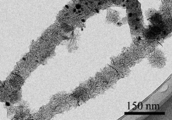
- FIG. 2 is a transmission electron microscope (TEM) photograph of the fibrous carbon nanohorn aggregate according to the present invention.
- FIG. 3 is a TEM photograph of spherical carbon nanohorn aggregates produced together with fibrous carbon nanohorn aggregates by the method of the present invention.
- Each single-layer carbon nanohorn constituting the fibrous carbon nanohorn aggregate of FIG. 2 according to the present embodiment is similar to the conventional single-layer carbon nanohorn constituting the spherical carbon nanohorn aggregate of FIG. The same.
- the fibrous carbon nanohorn aggregate is formed by connecting carbon nanohorn aggregates of seed type, bud type, dahlia type, petal dahlia type, and petal type (graphene sheet structure), that is, one type in the fibrous structure.
- a plurality of these carbon nanohorn aggregates are included.
- the catalyst metal exists inside or outside the fibrous carbon nanohorn aggregate or the spherical carbon nanohorn aggregate (non-transparent particles in FIG. 2). ).
- a fibrous carbon nanohorn aggregate is produced by the production method according to the present invention, a spherical carbon nanohorn aggregate is simultaneously generated.
- FIG. 4 is a scanning electron microscope (SEM) photograph of fibrous carbon nanohorn aggregates and spherical carbon nanohorn aggregates produced according to the present invention.
- the fibrous carbon nanohorn aggregate is fibrous and thus hardly re-aggregates, and has a structure excellent in dispersibility because single-layer carbon nanohorn aggregates are aggregated.
- the fibrous carbon nanohorn aggregate and the spherical carbon nanohorn aggregate may be referred to simply as a carbon nanohorn aggregate.
- the fibrous carbon nanohorn aggregate and the spherical carbon nanohorn aggregate can be separated using a centrifugal separation method, a difference in sedimentation speed after being dispersed in a solvent, gel permeation chromatography, or the like. .
- assembly it can remove by the separation by the centrifugation method, the difference in sedimentation speed, and size.
- the “fibrous” as used herein refers to a material that can maintain its shape to some extent even when the above separation operation is performed, and simply a plurality of spherical carbon nanohorn aggregates that appear to be fibrous at first glance. Different.
- the fibrous carbon nanohorn aggregate according to the present invention is not limited to the above structure as long as the single-layer carbon nanohorns are aggregated in a fibrous form. Fine holes can be formed in the single-walled carbon nanohorn of the carbon nanohorn aggregate, and the substance can be taken into the single-walled carbon nanohorn from the opening. Since the single-walled carbon nanohorn includes a structure other than a six-membered ring at the tip and side portions, the portion is preferentially oxidized and opened by oxidation treatment. Since the specific surface area is greatly improved by opening the holes, the use of a carbon nanohorn aggregate having a large specific surface area is advantageous for producing a planar structure.
- each single-walled carbon nanohorn obtained is approximately 1 nm to 5 nm, and the length is 30 nm to 100 nm.
- the fibrous carbon nanohorn aggregate can have a diameter of about 30 nm to 200 nm and a length of about 1 ⁇ m to 100 ⁇ m.
- the spherical carbon nanohorn aggregate has a diameter of about 30 nm to 200 nm and a substantially uniform size.
- the obtained carbon nanohorn aggregate is formed of a seed type, a bud type, a dahlia type, a petal-dahlia type, a petal type alone or in combination.
- the seed type has a shape with little or no square protrusions on the surface of the assembly
- the bud type has a shape with some angular protrusions on the surface of the assembly
- the dahlia type has the surface of the assembly.
- the petal type is a shape with petal-like protrusions on the surface of the aggregate.
- the petal structure is a graphene sheet structure having a width of 50 to 200 nm, a thickness of 0.34 to 10 nm, and 2 to 30 sheets.
- the petal-dahlia type is an intermediate structure between the dahlia type and the petal type.
- the spherical carbon nanohorn aggregates are generated in a mixed state separately from the fibrous carbon nanohorn aggregates.
- the form and particle size of the produced carbon nanohorn aggregate vary depending on the type and flow rate of the gas.
- the method for producing the fibrous carbon nanohorn aggregate is a catalyst-containing carbon target (referred to as a catalyst-containing carbon target), a nitrogen atmosphere, an inert atmosphere, while rotating the target in a container in which the catalyst-containing carbon target is placed.
- the target is heated by laser ablation under hydrogen, carbon dioxide, or a mixed atmosphere to evaporate the target.
- Fibrous carbon nanohorn aggregates and spherical carbon nanohorn aggregates are obtained in the process of cooling the evaporated carbon and the catalyst.
- a method using a carbon target containing a catalyst has been known in part as a method for producing carbon nanotubes
- conventional carbon nanohorn aggregates spherical carbon nanohorn aggregates
- a graphite target was used.
- an arc discharge method or a resistance heating method can be used in addition to the laser ablation method.
- the laser ablation method is more preferable from the viewpoint of continuous production at room temperature and atmospheric pressure.
- the laser ablation (LA) method applied in the present invention irradiates the target with a laser pulsed or continuously, and when the irradiation intensity exceeds a threshold value, the target converts energy, and as a result, the plume
- the generated product is deposited on a substrate provided downstream of the target, or is generated in a space in the apparatus and recovered in a recovery chamber.
- a CO 2 laser, a YAG laser, an excimer laser, a semiconductor laser, or the like can be used, and a CO 2 laser that can easily increase the output is most suitable.
- the CO 2 laser can use an output of 1 kW / cm 2 to 1000 kW / cm 2 and can be performed by continuous irradiation and pulse irradiation. Continuous irradiation is desirable for the production of carbon nanohorn aggregates.
- Laser light is condensed and irradiated by a ZnSe lens or the like. Moreover, it can synthesize
- the laser output is preferably 15 kW / cm 2 or more, and 30 to 300 kW / cm 2 is most effective.
- the laser output is 15 kW / cm 2 or more, the target is appropriately evaporated, and the production of the carbon nanohorn aggregate is facilitated.
- it is 300 kW / cm ⁇ 2 >, the increase in amorphous carbon can be suppressed.
- the pressure in the container (chamber) can be used at 13332.2 hPa (10000 Torr) or less, but the closer the pressure is to a vacuum, the more easily carbon nanotubes are produced, and the carbon nanohorn aggregates cannot be obtained.
- it is used at 666.61 hPa (500 Torr)-1266.56 hPa (950 Torr), more preferably near normal pressure (1013 hPa (1 atm ⁇ 760 Torr)) for mass synthesis and cost reduction.
- the irradiation area can also be controlled by the laser output and the degree of condensing by the lens, and 0.005 cm 2 to 1 cm 2 can be used.
- the catalyst can be used alone or as a mixture of Fe, Ni, and Co.
- the concentration of the catalyst can be appropriately selected, but is preferably 0.1% by mass to 10% by mass, more preferably 0.5% by mass to 5% by mass with respect to carbon.
- assembly becomes it sure that it is 0.1 mass% or more. Moreover, when it is 10 mass% or less, the increase in target cost can be suppressed.
- the inside of the container can be used at any temperature, preferably 0 to 100 ° C., and more preferably used at room temperature for mass synthesis and cost reduction.
- Nitrogen gas, inert gas, hydrogen gas, CO 2 gas, or the like is introduced into the container alone or in a mixture to achieve the above atmosphere. From the viewpoint of cost, nitrogen gas and Ar gas are preferable. These gases circulate in the reaction vessel, and the produced substances can be recovered by the gas flow. Moreover, it is good also as a closed atmosphere with the introduced gas. An arbitrary amount can be used as the atmospheric gas flow rate, but a range of 0.5 L / min to 100 L / min is preferable. In the process of evaporating the target, the gas flow rate is controlled to be constant. The gas flow rate can be made constant by combining the supply gas flow rate and the exhaust gas flow rate.
- part of the carbon skeleton may be substituted with a catalytic metal element, a nitrogen atom, or the like.
- the carbon nanohorn aggregate When fine holes are formed in the carbon nanohorn aggregate (opening), it can be performed by oxidation treatment. By this oxidation treatment, surface functional groups containing oxygen are formed in the pores.
- a gas phase process and a liquid phase process can be used.
- heat treatment is performed in an atmosphere gas containing oxygen such as air, oxygen, carbon dioxide, or the like. Among these, air is suitable from the viewpoint of cost.
- the temperature can be in the range of 300 to 650 ° C., and 400 to 550 ° C. is more suitable. Above 300 ° C, there is no concern that carbon will not burn and cannot be opened. In addition, at 650 ° C. or lower, the entire carbon nanohorn aggregate can be prevented from burning.
- a liquid phase process it is performed in a liquid containing an oxidizing substance such as nitric acid, sulfuric acid, and hydrogen peroxide.
- an oxidizing substance such as nitric acid, it can be used in a temperature range from room temperature to 120 ° C. If it is 120 degrees C or less, an oxidizing power will not become high too much and it will not oxidize more than necessary.
- hydrogen peroxide it can be used in the temperature range of room temperature to 100 ° C., more preferably 40 ° C. or higher. In the temperature range of 40 to 100 ° C., the oxidizing power acts efficiently, and the holes can be formed efficiently. In the liquid phase process, it is more effective to use light irradiation together.
- the catalytic metal contained in the formation of the carbon nanohorn aggregate can be removed before the oxidation treatment.
- the catalytic metal can be removed because it dissolves in nitric acid, sulfuric acid and hydrochloric acid. From the viewpoint of ease of use, hydrochloric acid is suitable.
- the temperature at which the catalyst is dissolved can be appropriately selected. However, when the catalyst is sufficiently removed, it is desirable to carry out the heating to 70 ° C. or higher. When nitric acid or sulfuric acid is used, catalyst removal and pore formation can be performed simultaneously or sequentially.
- the catalyst since the catalyst may be covered with a carbon film when the carbon nanohorn aggregate is formed, it is desirable to perform a pretreatment to remove the carbon film.
- the pretreatment is desirably performed at about 250 to 450 ° C. in air.
- Some openings may be formed as described above at 300 ° C. or higher. However, in the present invention, the formation of openings is not a problem because it is a preferred embodiment depending on the application.
- the obtained carbon nanohorn aggregate can be improved in crystallinity by heat treatment in a non-oxidizing atmosphere such as inert gas, hydrogen, or vacuum.
- the heat treatment temperature can be 800 to 2000 ° C., but preferably 1000 to 1500 ° C.
- a surface functional group containing oxygen is formed in the opening, but it can be removed by heat treatment.
- the heat treatment temperature can be 150 to 2000 ° C. In order to remove surface functional groups such as carboxyl groups and hydroxyl groups, 150 ° C. to 600 ° C. is desirable.
- the carbonyl group etc. which are surface functional groups 600 degreeC or more is desirable.
- the surface functional group can be removed by reduction in a gas or liquid atmosphere. Hydrogen can be used for the reduction in the gas atmosphere, and it can be combined with the improvement of the crystallinity. Hydrazine or the like can be used in a liquid atmosphere.
- the mixture of the fibrous carbon nanohorn aggregate and the spherical carbon nanohorn aggregate (hereinafter also referred to as the carbon nanohorn aggregate mixture) can be used as it is, or the fibrous carbon nanohorn aggregate can be isolated or the pores can be formed. After formation, the film can be thinned and used as a planar structure.
- the planar structure according to the present invention may contain at least one mixed material of carbon, carbon compound, metal, metalloid, and oxide.
- the carbon for example, one or more selected from carbon black such as graphite, graphitizable carbon, non-graphitizable carbon, activated carbon, acetylene black and ketjen black, carbon nanotube, and graphene can be used.
- the carbon compound include silicon carbide, nitrogen carbide, silicon carbonitride, and the like.
- the metal one or more selected from iron, nickel, manganese, copper, silver, gold, platinum, aluminum, titanium, zinc, and chromium can be used.
- the metalloid at least one of boron and silicon can be used.
- the oxide one or more of the above metal or metalloid oxides can be used.
- a carbon nanohorn aggregate mixture and, if necessary, the above mixture are dispersed in a suitable solvent such as alcohol, and the obtained dispersion is applied onto a substrate and dried. It is obtained by doing.
- the carbon nanohorn aggregate mixture can be made into a thin film without a binder, but a binder may be used.
- a binder various resin materials can be used, but at least one selected from polyvinylidene fluoride, acrylic resin, styrene butadiene rubber, imide resin, imidoamide resin, polytetrafluoroethylene resin, and polyamide resin is preferable.
- the planar structure containing the fibrous carbon nanohorn aggregate can be used for various applications that take advantage of the characteristics of the carbon nanohorn aggregate.
- the carbon nanohorn aggregate contributes to improvement in conductivity when the fibrous structure is thinned as a conductive path. It also excels in catalytic activity, adsorption / absorption, and thermal conductivity. For example, it can be used for electrode materials of lithium ion batteries, fuel cells, capacitors, electrochemical actuators, air cells, and solar cells. It can also be used for electromagnetic shields, heat conductive sheets, heat dissipation sheets, protective sheets, filters, and absorbent materials.
- Example 1 Fibrous carbon nanohorn aggregates and spherical carbon nanohorn aggregates were prepared by irradiating a carbon target containing about 5% by mass of iron with a CO 2 laser in a nitrogen atmosphere (sample 1). Details of the experiment are shown below. A carbon target containing iron was rotated at 2 rpm. The energy density of the CO 2 laser was continuously irradiated at 150 kW / cm 2 , and the chamber temperature was room temperature. In the chamber, the gas flow rate was adjusted to 10 L / min. The pressure was controlled at 933.254 to 1266.559 hPa (700 to 950 Torr). In addition, as a comparative sample, a laser ablated sample was also produced under a nitrogen atmosphere using a carbon target not containing a catalyst under the same conditions (Sample 2).
- FIG. 4 is an SEM photograph of Sample 1. Fibrous and spherical materials are observed. The fibrous substance has a diameter of about 30 to 100 nm and a length of several ⁇ m to several tens of ⁇ m. Most of the spherical substances have a substantially uniform size within a diameter range of about 30 to 200 nm. 2 and 3 are TEM photographs of the product. From the observation results of the fibrous substance, it was found that single-walled carbon nanohorns having a diameter of about 1-5 nm and a length of about 40-50 nm are gathered in a fibrous form.
- Sample 1 (1 mg) was mixed with 30 ml of ethanol and subjected to ultrasonic dispersion for 15 minutes to prepare a dispersion. The obtained dispersion was dropped on a silicon substrate and dried. It repeated until the film thickness became 1 micrometer. The laser microscope image of the obtained thin film is shown in FIG. As a result, it was confirmed that a uniform film was formed.
- FIG. 6 shows a thin film produced from Sample 2 by the same method. As a result, it was confirmed that the surface formed unevenness and cracks. Sample 1 is considered to maintain a uniform state because the fibrous structure prevents reaggregation of spherical aggregates and the fibrous structure is entangled when ethanol is dried.
- a thin film using Sample 3 (activated carbon (YP50F: manufactured by Kuraray)) and Sample 4 (1: 1 mixture of Sample 3 and Sample 1) was prepared in the same manner as Sample 1.
- the sheet resistivity of the thin film using Samples 1 to 4 was measured.
- four prober tips were arranged in one row, current I was passed through the outer electrode pair, and voltage V between the inner electrode pair was measured.
- the obtained sheet resistivity was 1 ⁇ cm, 15 ⁇ cm, 25 ⁇ cm, and 10 ⁇ cm for Samples 1, 2, 3, and 4, respectively. From this result, it was found that Sample 1 having a uniform thin film and excellent conductivity had the lowest resistivity. Samples 2 and 3 where it is difficult to form a uniform thin film have high resistivity values.
- the sample 4 added the sample 1 and the thin film of the sample 3 was equalized, and the resistivity decreased.
- Example 2 Electrode material for electric double layer capacitor
- Samples 1 and 2 were mixed at 80% by mass and PVDF at 20% by mass, respectively, and N-methyl-2-pyrrolidinone was further mixed and stirred sufficiently to prepare a paste.
- the obtained paste was applied to an Al current collector with a thickness of about 100 ⁇ m.
- the electrode body was pressure-molded with the roll press. Furthermore, this electrode body was vacuum-dried at 60 ° C. for 24 hours, and punched into a circle having a diameter of 12 mm to obtain an electrode plate for an electric double layer capacitor (positive electrode, negative electrode).
- a coin cell was prepared (sample) A, sample B).
- Samples 1 and 2 were heated in air at 450 ° C. and 500 ° C., respectively, to prepare samples 5 and 6 that were oxidized, and coin cells were prepared (sample C and sample D), respectively.
- Samples 5 and 6 single-walled carbon nanohorns were opened, and the inside could be used, and the specific surface area was approximately four times as large.
- Coin cells were set in a charge / discharge tester, and charged and discharged at a constant current from a voltage of 0 V to 2.5 V.
- rate characteristics rapid charge / discharge characteristics
- the discharge characteristics were evaluated at 0.1, 1, 10 A / g in the same voltage range as above (Table 1). It was found that the capacity at the low rate is the largest for sample C and depends on the specific surface area.
- Sample A and Sample C had a small capacity decrease due to an increase in discharge rate. This is because the electrode film containing the fibrous carbon nanohorn aggregate is produced uniformly, thereby reducing the internal resistance of the electrode.
- the planar structure of the present invention can be used for electrode materials for lithium ion batteries, fuel cells, capacitors, electrochemical actuators, air cells, and solar cells. It can also be used for electromagnetic shields, heat conductive sheets, heat dissipation sheets, protective sheets, filters, and absorbent materials.
- Embodiments of the present invention include configurations described in the following supplementary notes, but are not limited to these configurations.
- Appendix 1 A planar structure comprising a fibrous carbon nanohorn aggregate in which a plurality of single-layer carbon nanohorns are aggregated in a fibrous form.
- Appendix 2 The planar structure according to appendix 1, wherein the fibrous carbon nanohorn aggregate has a diameter of 30 nm to 200 nm and a length of 1 ⁇ m to 100 ⁇ m.
- Appendix 3) The planar structure according to appendix 1 or 2, wherein each single-walled carbon nanohorn has a diameter of 1 nm to 5 nm, a length of 30 nm to 100 nm, and a tip having a horn shape.
- the fibrous carbon nanohorn aggregate is any one of appendices 1 to 3, wherein at least one carbon nanohorn aggregate of a seed type, a dahlia type, a bud type, a petal dahlia type, and a petal type is connected in a fibrous form
- the planar structure described in 1. (Appendix 5) Furthermore, it includes at least one kind of spherical carbon nanohorn aggregate of seed type, bud type, dahlia type, petal dahlia type, petal type, which does not constitute the fibrous carbon nanohorn aggregate.
- the planar structure according to any one of the above. (Appendix 6) 6.
- Appendix 7 The planar structure according to any one of supplementary notes 1 to 6, further comprising at least one of carbon, a carbon compound, a metal, a metalloid, and an oxide.
- the carbon is at least one selected from graphite, graphitizable carbon, non-graphitizable carbon, activated carbon, carbon black, carbon nanotube, graphene, and the metal is iron, nickel, manganese, copper, silver, One or more selected from gold, platinum, aluminum, titanium, zinc and chromium, the semimetal is at least one of boron and silicon, and the oxide is one or more of the above metals and metalloid oxides
- Appendix 11 11.
- Appendix 12 11.
- Appendix 13 11.
- Appendix 14 14.
- Appendix 15 11.
- Appendix 16 11. The planar structure according to any one of appendices 1 to 10, which is an electrode material for an air battery.
- Appendix 17 11. The planar structure according to any one of appendices 1 to 10, which is an electrode material for a solar cell.
- Appendix 18 11. The planar structure according to any one of appendices 1 to 10, which is an electromagnetic shield.
- Appendix 19 11. The planar structure according to any one of appendices 1 to 10, which is a heat conductive sheet.
- Appendix 20 11. The planar structure according to any one of appendices 1 to 10, which is a heat dissipation sheet.
- (Appendix 24) The planar structure according to appendix 22, wherein the filter is a dust collection filter.
- Appendix 27 The planar structure according to appendix 26, wherein the absorbent material absorbs gas or liquid.
- Appendix 28 Item 27. The planar structure according to appendix 26, which absorbs a substance having a lawn property.
Abstract
The present invention uses a flat structure 1 characterized by including fibrous carbon nanohorn aggregates 2 in which a plurality of single-walled carbon nanohorns are aggregated in fibrous fashion, particularly a flat structure 1 in which spherical carbon nanohorn aggregates 3 are mixed. A flat structure of such description including fibrous carbon nanohorn aggregates can be used in an electrode material for a lithium ion cell, a fuel cell, a capacitor, an electrochemical actuator, an air cell, a solar cell, or the like, and can also be used in an electromagnetic shield, a thermal conducting sheet, a heat dissipating sheet, a protective sheet, a filter, or an absorbent material.
Description
本発明は、繊維状カーボンナノホーン集合体を含んだ平面構造体に関するものである。
The present invention relates to a planar structure including a fibrous carbon nanohorn aggregate.
従来、炭素材料は、導電材、触媒担体、吸着剤、分離剤、インク、トナーなどとして利用されており、近年ではカーボンナノチューブ、カーボンナノホーン等のナノサイズの大きさを有するナノ炭素材の出現で、その構造体としての特徴が注目され、その用途については、以下の特許文献1(カーボンナノホーン)、特許文献2(DDS)、特許文献3(固体潤滑剤)、特許文献4(メタンガスの吸蔵)、特許文献5(吸着剤)、特許文献6(メタン分解触媒)、特許文献7(触媒担体)及び特許文献8(導電材)に示されるように鋭意研究が行われてきた。
Conventionally, carbon materials have been used as conductive materials, catalyst carriers, adsorbents, separating agents, inks, toners, etc. In recent years, with the advent of nanocarbon materials having nano-sized sizes such as carbon nanotubes and carbon nanohorns. The features of the structure have attracted attention, and the uses thereof are described in Patent Document 1 (carbon nanohorn), Patent Document 2 (DDS), Patent Document 3 (solid lubricant), and Patent Document 4 (occlusion of methane gas). As described in Patent Document 5 (adsorbent), Patent Document 6 (methane decomposition catalyst), Patent Document 7 (catalyst support) and Patent Document 8 (conductive material), intensive studies have been conducted.
このようなナノ炭素材は、それぞれの材料の特性を生かした形状として各用途に使用される。特に、薄膜、シート、板などの平面構造体として使用する場合がある。
しかしながら、薄膜などの平面構造体を作製する際、カーボンナノチューブは分散しにくいため、ペースト化しにくく、均一な薄膜を作製するのが難しいという課題がある。一方、従来のカーボンナノホーン集合体は、球状構造体で高分散であり、ペースト化が容易であるが、薄膜を作製する際、塗布後の乾燥時に再凝集するため均一な薄膜を形成することが難しいという課題がある。さらに、球状構造体を薄膜化する際、カーボンナノホーン集合体だけでは薄膜化できずバインダー(結着材)が必要であるという課題がある。 Such a nano carbon material is used for each application as a shape utilizing the characteristics of each material. In particular, it may be used as a planar structure such as a thin film, sheet, or plate.
However, when producing a planar structure such as a thin film, the carbon nanotubes are difficult to disperse, making it difficult to form a paste, making it difficult to produce a uniform thin film. On the other hand, conventional carbon nanohorn aggregates have a spherical structure and are highly dispersed and can be easily pasted. However, when a thin film is produced, a uniform thin film can be formed because it reaggregates during drying after coating. There is a problem that it is difficult. Furthermore, when the spherical structure is thinned, there is a problem that a binder (binder) is necessary because the carbon nanohorn aggregate alone cannot be thinned.
本発明では、カーボンナノホーン集合体を含んで均一性に優れた平面構造体を提供することを目的とする。
An object of the present invention is to provide a planar structure having excellent uniformity including a carbon nanohorn aggregate.
そこで、本発明者は、カーボンナノホーン集合体を含んだ平面構造体について鋭意検討した結果、本発明者が見出した繊維状のカーボンナノホーン集合体を用いることで均一性に優れた平面構造体が得られることを見出した。
Therefore, as a result of earnestly examining the planar structure including the carbon nanohorn aggregate, the present inventor obtained a planar structure excellent in uniformity by using the fibrous carbon nanohorn aggregate discovered by the present inventor. I found out that
すなわち、本発明の一形態によれば、複数の単層カーボンナノホーンが繊維状に集合している繊維状カーボンナノホーン集合体を含んでいることを特徴とする平面構造体が提供される。
That is, according to one aspect of the present invention, there is provided a planar structure characterized by including a fibrous carbon nanohorn aggregate in which a plurality of single-walled carbon nanohorns are aggregated in a fibrous form.
また、本発明の別の形態によれば、前記繊維状のカーボンナノホーン集合体は、種型、つぼみ型、ダリア型、ペタルダリア型、ペタル型のうちの少なくとも一種類のカーボンナノホーン集合体が繊維状に繋がったものであることを特徴としている。
また、さらに前記繊維状のカーボンナノホーン集合体を構成しない、種型、つぼみ型、ダリア型、ペタルダリア型、ペタル型の少なくとも一種類の球状カーボンナノホーン集合体を含むことを特徴としている。
さらに前記カーボンナノホーン集合体に含まれる単層カーボンナノホーンの一部が開孔部を有することを特徴としている。
さらに前記カーボンナノホーン集合体が、炭素、炭素化合物、金属、半金属、酸化物の少なくとも一種類含むことを特徴とする平面構造体が提供される。 According to another aspect of the present invention, the fibrous carbon nanohorn aggregate is a seed-type, bud-type, dahlia-type, petal-dahlia-type, or petal-type at least one type of carbon nanohorn aggregate. It is characterized by being connected to.
Further, it is characterized in that it contains at least one kind of spherical carbon nanohorn aggregates of seed type, bud type, dahlia type, petal dahlia type, and petal type, which does not constitute the fibrous carbon nanohorn aggregate.
Further, a part of the single-walled carbon nanohorn included in the carbon nanohorn aggregate has an opening.
Further, a planar structure is provided in which the carbon nanohorn aggregate includes at least one of carbon, a carbon compound, a metal, a metalloid, and an oxide.
本発明の一形態に係る繊維状カーボンナノホーン集合体を含んだ平面構造体は、100nm~10mmの厚みを有する。なた、前記繊維状カーボンナノホーン集合体の直径が30nm~200nm、長さが1μm~100μmである。さらに、各々の単層カーボンナノホーンが、直径が1nm~5nm、長さが30nm~100nmであり、先端がホーン状である。
The planar structure including the fibrous carbon nanohorn aggregate according to one embodiment of the present invention has a thickness of 100 nm to 10 mm. The fibrous carbon nanohorn aggregate has a diameter of 30 nm to 200 nm and a length of 1 μm to 100 μm. Further, each single-walled carbon nanohorn has a diameter of 1 nm to 5 nm, a length of 30 nm to 100 nm, and a tip having a horn shape.
本発明によれば、繊維状のカーボンナノホーン集合体を使用することで均一な平面構造体が提供される。
According to the present invention, a uniform planar structure is provided by using a fibrous carbon nanohorn aggregate.
本発明は、上記の通りの特徴を持つものであるが、以下に実施の形態について説明する。
図1は、本発明の一実施形態例に係る繊維状のカーボンナノホーン集合体を含んでいる平面構造体の概略図である。図1(B)は図1(A)の拡大図である。ここで平面構造体1は、繊維状のカーボンナノホーン集合体2を含み、球状のカーボンナノホーン集合体3を含むことができる。
繊維状のカーボンナノホーン集合体2は、従来の繊維状物質とは異なり高分散性を有するため、他の物質等を容易に混ぜることができる。さらに溶剤等で混ぜたペースト等で塗布後の乾燥時に上記繊維状カーボンナノホーン集合体が再凝集を防ぐため優れた成形性を有する均一な平面構造体を生成する。また、繊維状構造が絡み合うことで、バインダー等を使用せず、薄膜化すこともできる。バインダーを使用する場合も使用量を削減できる。さらに、分散性に優れる球状のカーボンナノホーン集合体と同時に形成できるため、従来の繊維状材料とも容易に混合することができ、均一な平面構造体を生成することもできる。
平面構造体1の厚さは、用途により適宜選択できる。しかしながら、実用的に100nm~10mmが好ましい。 The present invention has the above-described features, and embodiments will be described below.
FIG. 1 is a schematic view of a planar structure including a fibrous carbon nanohorn assembly according to an embodiment of the present invention. FIG. 1B is an enlarged view of FIG. Here, theplanar structure 1 includes a fibrous carbon nanohorn aggregate 2 and can include a spherical carbon nanohorn aggregate 3.
Unlike the conventional fibrous substance, the fibrouscarbon nanohorn aggregate 2 has high dispersibility, so that other substances can be easily mixed. Furthermore, since the fibrous carbon nanohorn aggregates prevent re-aggregation during drying after application with a paste mixed with a solvent or the like, a uniform planar structure having excellent moldability is generated. Further, since the fibrous structure is intertwined, a thin film can be formed without using a binder or the like. The amount used can also be reduced when using a binder. Furthermore, since it can be formed simultaneously with a spherical carbon nanohorn aggregate excellent in dispersibility, it can be easily mixed with a conventional fibrous material, and a uniform planar structure can be generated.
The thickness of theplanar structure 1 can be appropriately selected depending on the application. However, practically 100 nm to 10 mm is preferable.
図1は、本発明の一実施形態例に係る繊維状のカーボンナノホーン集合体を含んでいる平面構造体の概略図である。図1(B)は図1(A)の拡大図である。ここで平面構造体1は、繊維状のカーボンナノホーン集合体2を含み、球状のカーボンナノホーン集合体3を含むことができる。
繊維状のカーボンナノホーン集合体2は、従来の繊維状物質とは異なり高分散性を有するため、他の物質等を容易に混ぜることができる。さらに溶剤等で混ぜたペースト等で塗布後の乾燥時に上記繊維状カーボンナノホーン集合体が再凝集を防ぐため優れた成形性を有する均一な平面構造体を生成する。また、繊維状構造が絡み合うことで、バインダー等を使用せず、薄膜化すこともできる。バインダーを使用する場合も使用量を削減できる。さらに、分散性に優れる球状のカーボンナノホーン集合体と同時に形成できるため、従来の繊維状材料とも容易に混合することができ、均一な平面構造体を生成することもできる。
平面構造体1の厚さは、用途により適宜選択できる。しかしながら、実用的に100nm~10mmが好ましい。 The present invention has the above-described features, and embodiments will be described below.
FIG. 1 is a schematic view of a planar structure including a fibrous carbon nanohorn assembly according to an embodiment of the present invention. FIG. 1B is an enlarged view of FIG. Here, the
Unlike the conventional fibrous substance, the fibrous
The thickness of the
球状カーボンナノホーン集合体のような球状構造体は、溶剤等に分散したペースト等を用いて薄膜化する際、分散性が損なわれて再凝集するため均一なシート状構造を作製することが難しい。しかしながら、繊維状カーボンナノホーン集合体は、再凝集しないため分散構造が維持され、均一な薄膜を含む平面構造体の形成が可能となる。さらに、繊維状カーボンナノホーン集合体は、高分散性を有するため他の球状構造体や繊維状構造体を容易に混ぜることができる。
A spherical structure such as a spherical carbon nanohorn aggregate is difficult to produce a uniform sheet-like structure because it loses its dispersibility and re-aggregates when it is thinned using a paste or the like dispersed in a solvent. However, since the fibrous carbon nanohorn aggregate does not re-aggregate, the dispersed structure is maintained, and a planar structure including a uniform thin film can be formed. Furthermore, since the fibrous carbon nanohorn aggregate has high dispersibility, other spherical structures and fibrous structures can be easily mixed.
図2は、本発明に係る繊維状のカーボンナノホーン集合体の透過型電子顕微鏡(TEM)写真である。図3は、本発明の方法によって繊維状のカーボンナノホーン集合体と共に生成した球状のカーボンナノホーン集合体のTEM写真である。本実施形態例に係る図2の繊維状のカーボンナノホーン集合体を構成している各単層カーボンナノホーンは、従来と同様に、図3の球状のカーボンナノホーン集合体を構成する単層カーボンナノホーンと同じである。繊維状のカーボンナノホーン集合体は、種型、つぼみ型、ダリア型、ペタルダリア型、ペタル型(グラフェンシート構造)のカーボンナノホーン集合体が繋がって形成されており、すなわち、繊維状構造中に1種類または複数のこれらカーボンナノホーン集合体が含まれている。また、触媒金属を使用したターゲットを蒸発させて作製するため、繊維状のカーボンナノホーン集合体や球状のカーボンナノホーン集合体の内部または外部に、触媒金属が存在する(図2中の非透過の粒子)。本発明に係る製造方法により繊維状のカーボンナノホーン集合体を製造すると、球状のカーボンナノホーン集合体が同時に生成される。
FIG. 2 is a transmission electron microscope (TEM) photograph of the fibrous carbon nanohorn aggregate according to the present invention. FIG. 3 is a TEM photograph of spherical carbon nanohorn aggregates produced together with fibrous carbon nanohorn aggregates by the method of the present invention. Each single-layer carbon nanohorn constituting the fibrous carbon nanohorn aggregate of FIG. 2 according to the present embodiment is similar to the conventional single-layer carbon nanohorn constituting the spherical carbon nanohorn aggregate of FIG. The same. The fibrous carbon nanohorn aggregate is formed by connecting carbon nanohorn aggregates of seed type, bud type, dahlia type, petal dahlia type, and petal type (graphene sheet structure), that is, one type in the fibrous structure. Alternatively, a plurality of these carbon nanohorn aggregates are included. In addition, since the target using the catalyst metal is evaporated, the catalyst metal exists inside or outside the fibrous carbon nanohorn aggregate or the spherical carbon nanohorn aggregate (non-transparent particles in FIG. 2). ). When a fibrous carbon nanohorn aggregate is produced by the production method according to the present invention, a spherical carbon nanohorn aggregate is simultaneously generated.
図4は、本発明によって作製された繊維状のカーボンナノホーン集合体と球状のカーボンナノホーン集合体の走査型電子顕微鏡(SEM)写真である。図4のように繊維状のカーボンナノホーン集合体は、繊維状であるため再凝集し難く、単層のカーボンナノホーンが集合しているため分散性に優れた構造である。
FIG. 4 is a scanning electron microscope (SEM) photograph of fibrous carbon nanohorn aggregates and spherical carbon nanohorn aggregates produced according to the present invention. As shown in FIG. 4, the fibrous carbon nanohorn aggregate is fibrous and thus hardly re-aggregates, and has a structure excellent in dispersibility because single-layer carbon nanohorn aggregates are aggregated.
本明細書では、繊維状のカーボンナノホーン集合体と球状のカーボンナノホーン集合体とを合わせて、単にカーボンナノホーン集合体と呼ぶことがある。なお、繊維状のカーボンナノホーン集合体と球状のカーボンナノホーン集合体とは、遠心分離法や、溶媒に分散した後沈降速度の違い、ゲル透過クロマトグラフィーなどを利用して分離することが可能である。さらに、カーボンナノホーン集合体以外の不純物が含まれる場合、遠心分離法、沈降速度の違い、サイズによる分離により除去できる。また、生成条件を変えることで、繊維状のカーボンナノホーン集合体と球状のカーボンナノホーン集合体の比率を変えることが可能である。なお、ここでいう「繊維状」とは、上記の分離操作を行ってもその形状をある程度維持できるものをいい、単に球状のカーボンナノホーン集合体が複数連なって、一見繊維状に見えるものとは異なる。
In this specification, the fibrous carbon nanohorn aggregate and the spherical carbon nanohorn aggregate may be referred to simply as a carbon nanohorn aggregate. The fibrous carbon nanohorn aggregate and the spherical carbon nanohorn aggregate can be separated using a centrifugal separation method, a difference in sedimentation speed after being dispersed in a solvent, gel permeation chromatography, or the like. . Furthermore, when impurities other than a carbon nanohorn aggregate | assembly are contained, it can remove by the separation by the centrifugation method, the difference in sedimentation speed, and size. Moreover, it is possible to change the ratio of the fibrous carbon nanohorn aggregate and the spherical carbon nanohorn aggregate by changing the generation conditions. The “fibrous” as used herein refers to a material that can maintain its shape to some extent even when the above separation operation is performed, and simply a plurality of spherical carbon nanohorn aggregates that appear to be fibrous at first glance. Different.
本発明に係る繊維状のカーボンナノホーン集合体は、単層カーボンナノホーンが繊維状に集合していれば良く、上記の構造のみに限定されない。カーボンナノホーン集合体の単層カーボンナノホーンに微細な穴を形成させ、その開孔部から単層カーボンナノホーン内部に物質を取込むことができる。単層カーボンナノホーンは、先端部や側面部に6員環以外の構造を含むため、酸化処理により優先的にその部分が酸化され開孔する。開孔することで比表面積が大きく向上するため、比表面積の大きなカーボンナノホーン集合体の使用が好ましい平面構造体の作製に有利となる。
The fibrous carbon nanohorn aggregate according to the present invention is not limited to the above structure as long as the single-layer carbon nanohorns are aggregated in a fibrous form. Fine holes can be formed in the single-walled carbon nanohorn of the carbon nanohorn aggregate, and the substance can be taken into the single-walled carbon nanohorn from the opening. Since the single-walled carbon nanohorn includes a structure other than a six-membered ring at the tip and side portions, the portion is preferentially oxidized and opened by oxidation treatment. Since the specific surface area is greatly improved by opening the holes, the use of a carbon nanohorn aggregate having a large specific surface area is advantageous for producing a planar structure.
得られる各々の単層カーボンナノホーンの直径はおおよそ1nm~5nmであり、長さは30nm~100nmである。繊維状のカーボンナノホーン集合体は、直径が30nm~200nm程度で、長さが1μm~100μm程度とすることができる。一方、球状のカーボンナノホーン集合体は、直径が30nm~200nm程度でほぼ均一なサイズである。
The diameter of each single-walled carbon nanohorn obtained is approximately 1 nm to 5 nm, and the length is 30 nm to 100 nm. The fibrous carbon nanohorn aggregate can have a diameter of about 30 nm to 200 nm and a length of about 1 μm to 100 μm. On the other hand, the spherical carbon nanohorn aggregate has a diameter of about 30 nm to 200 nm and a substantially uniform size.
得られるカーボンナノホーン集合体は、種型、つぼみ型、ダリア型、ペタル-ダリア型、ペタル型が単独で、または、複合して形成される。種型は集合体の表面に角状の突起がほとんどみられない、あるいは全くみられない形状、つぼみ型は集合体の表面に角状の突起が多少みられる形状、ダリア型は集合体の表面に角状の突起が多数みられる形状、ペタル型は集合体の表面に花びら状の突起がみられる形状である。ペタル構造は、幅は50~200nm、厚みは0.34~10nm、2~30枚のグラフェンシート構造である。ペタル-ダリア型はダリア型とペタル型の中間的な構造である。球状のカーボンナノホーン集合体は、繊維状のカーボンナノホーン集合体とは別に混在した状態で生成される。生成するカーボンナノホーン集合体は、ガスの種類や流量によってその形態および粒径が変わる。
The obtained carbon nanohorn aggregate is formed of a seed type, a bud type, a dahlia type, a petal-dahlia type, a petal type alone or in combination. The seed type has a shape with little or no square protrusions on the surface of the assembly, the bud type has a shape with some angular protrusions on the surface of the assembly, and the dahlia type has the surface of the assembly. The petal type is a shape with petal-like protrusions on the surface of the aggregate. The petal structure is a graphene sheet structure having a width of 50 to 200 nm, a thickness of 0.34 to 10 nm, and 2 to 30 sheets. The petal-dahlia type is an intermediate structure between the dahlia type and the petal type. The spherical carbon nanohorn aggregates are generated in a mixed state separately from the fibrous carbon nanohorn aggregates. The form and particle size of the produced carbon nanohorn aggregate vary depending on the type and flow rate of the gas.
繊維状のカーボンナノホーン集合体の作製方法は、触媒を含有した炭素をターゲット(触媒含有炭素ターゲットという)とし、触媒含有炭素ターゲットを配置した容器内でターゲットを回転させながら窒素雰囲気、不活性雰囲気、水素、二酸化炭素、又は、混合雰囲気下でレーザーアブレーションによりターゲットを加熱し、ターゲットを蒸発させる。蒸発した炭素と触媒が冷える過程で繊維状のカーボンナノホーン集合体及び球状のカーボンナノホーン集合体が得られる。触媒を含有した炭素ターゲットを用いる方法は、カーボンナノチューブの製造方法として一部知られていたが、従来のカーボンナノホーン集合体(球状のカーボンナノホーン集合体)は、触媒を含まない純粋(100%)グラファイトターゲットが用いられていた。また作製方法として、上記レーザーアブレーション法以外にアーク放電法や抵抗加熱法を用いることができる。しかしながら、レーザーアブレーション法は、室温、大気圧中で連続生成できる観点からより好ましい。
The method for producing the fibrous carbon nanohorn aggregate is a catalyst-containing carbon target (referred to as a catalyst-containing carbon target), a nitrogen atmosphere, an inert atmosphere, while rotating the target in a container in which the catalyst-containing carbon target is placed. The target is heated by laser ablation under hydrogen, carbon dioxide, or a mixed atmosphere to evaporate the target. Fibrous carbon nanohorn aggregates and spherical carbon nanohorn aggregates are obtained in the process of cooling the evaporated carbon and the catalyst. Although a method using a carbon target containing a catalyst has been known in part as a method for producing carbon nanotubes, conventional carbon nanohorn aggregates (spherical carbon nanohorn aggregates) are pure (100%) containing no catalyst. A graphite target was used. As a manufacturing method, an arc discharge method or a resistance heating method can be used in addition to the laser ablation method. However, the laser ablation method is more preferable from the viewpoint of continuous production at room temperature and atmospheric pressure.
本発明で適用するレーザーアブレーション(Laser Ablation:LA)法は、レーザーをターゲットにパルス状又は連続して照射して、照射強度が閾値以上になると、ターゲットがエネルギーを変換し、その結果、プルームが生成され、生成物をターゲットの下流に設けた基板上に堆積させる、或いは装置内の空間に生成させ、回収室で回収する方法である。
The laser ablation (LA) method applied in the present invention irradiates the target with a laser pulsed or continuously, and when the irradiation intensity exceeds a threshold value, the target converts energy, and as a result, the plume In this method, the generated product is deposited on a substrate provided downstream of the target, or is generated in a space in the apparatus and recovered in a recovery chamber.
レーザーアブレーションには、CO2レーザー、YAGレーザー、エキシマレーザー、半導体レーザー等が使用可能で、高出力化が容易なCO2レーザーが最も適当である。CO2レーザーは、1kW/cm2~1000kW/cm2の出力が使用可能であり、連続照射及びパルス照射で行うことが出来る。カーボンナノホーン集合体の生成には連続照射の方が望ましい。レーザー光をZnSeレンズなどにより集光させ、照射させる。また、ターゲットを回転させることで連続的に合成することが出来る。ターゲット回転速度は任意に設定できるが、0.1~6rpmが特に好ましい、0.1rpm以上であればグラファイト化が抑制でき、また、6rpm以下であればアモルファスカーボンの増加を抑制できる。この時、レーザー出力は15kW/cm2以上が好ましく、30~300kW/cm2が最も効果的である。レーザー出力が15kW/cm2以上であれば、ターゲットが適度に蒸発し、カーボンナノホーン集合体の生成が容易となる。また300kW/cm2であれば、アモルファスカーボンの増加を抑制できる。容器(チャンバー)内の圧力は、13332.2hPa(10000Torr)以下で使用することができるが、圧力が真空に近くなるほど、カーボンナノチューブが生成しやすくなり、カーボンナノホーン集合体が得られなくなる。好ましくは666.61hPa(500Torr)-1266.56hPa(950Torr)で、より好ましくは常圧(1013hPa(1atm≒760Torr))付近で使用することが大量合成や低コスト化のためにも適当である。また照射面積もレーザー出力とレンズでの集光の度合いにより制御でき、0.005cm2~1cm2が使用できる。
For laser ablation, a CO 2 laser, a YAG laser, an excimer laser, a semiconductor laser, or the like can be used, and a CO 2 laser that can easily increase the output is most suitable. The CO 2 laser can use an output of 1 kW / cm 2 to 1000 kW / cm 2 and can be performed by continuous irradiation and pulse irradiation. Continuous irradiation is desirable for the production of carbon nanohorn aggregates. Laser light is condensed and irradiated by a ZnSe lens or the like. Moreover, it can synthesize | combine continuously by rotating a target. Although the target rotation speed can be arbitrarily set, 0.1 to 6 rpm is particularly preferable. If it is 0.1 rpm or more, graphitization can be suppressed, and if it is 6 rpm or less, an increase in amorphous carbon can be suppressed. At this time, the laser output is preferably 15 kW / cm 2 or more, and 30 to 300 kW / cm 2 is most effective. When the laser output is 15 kW / cm 2 or more, the target is appropriately evaporated, and the production of the carbon nanohorn aggregate is facilitated. Moreover, if it is 300 kW / cm < 2 >, the increase in amorphous carbon can be suppressed. The pressure in the container (chamber) can be used at 13332.2 hPa (10000 Torr) or less, but the closer the pressure is to a vacuum, the more easily carbon nanotubes are produced, and the carbon nanohorn aggregates cannot be obtained. Preferably, it is used at 666.61 hPa (500 Torr)-1266.56 hPa (950 Torr), more preferably near normal pressure (1013 hPa (1 atm≈760 Torr)) for mass synthesis and cost reduction. The irradiation area can also be controlled by the laser output and the degree of condensing by the lens, and 0.005 cm 2 to 1 cm 2 can be used.
触媒は、Fe、Ni、Coを単体で、又は混合して使用することができる。触媒の濃度は適宜選択できるが、炭素に対して、0.1質量%~10質量%が好ましく、0.5質量%~5質量%がより好ましい。0.1質量%以上であると、繊維状カーボンナノホーン集合体の生成が確実となる。また、10質量%以下の場合は、ターゲットコストの増加を抑制できる。
The catalyst can be used alone or as a mixture of Fe, Ni, and Co. The concentration of the catalyst can be appropriately selected, but is preferably 0.1% by mass to 10% by mass, more preferably 0.5% by mass to 5% by mass with respect to carbon. The production | generation of a fibrous carbon nanohorn aggregate | assembly becomes it sure that it is 0.1 mass% or more. Moreover, when it is 10 mass% or less, the increase in target cost can be suppressed.
容器内は任意の温度で使用でき、好ましくは、0~100℃であり、より好ましくは室温で使用することが大量合成や低コスト化のためにも適当である。
The inside of the container can be used at any temperature, preferably 0 to 100 ° C., and more preferably used at room temperature for mass synthesis and cost reduction.
容器内には、窒素ガスや、不活性ガス、水素ガス、CO2ガスなどを単独で又は混合して導入することで上記の雰囲気とする。コストの面からは、窒素ガス、Arガスが好ましい。これらのガスは反応容器内を流通し、生成する物質をこのガスの流れによって回収することが出来る。また導入したガスにより閉鎖雰囲気としてもよい。雰囲気ガス流量は、任意の量を使用できるが、好ましくは0.5L/min~100L/minの範囲が適当である。ターゲットが蒸発する過程ではガス流量を一定に制御する。ガス流量を一定にするには、供給ガス流量と排気ガス流量とを合わせることで行うことができる。常圧付近で行う場合は、供給ガスで容器内のガスを押出して排気することで行うことができる。
以上のようにして得られる繊維状カーボンナノホーン及びカーボンナノホーン集合体は、その炭素骨格の一部が触媒金属元素、窒素原子等で置換されていてもよい。 Nitrogen gas, inert gas, hydrogen gas, CO 2 gas, or the like is introduced into the container alone or in a mixture to achieve the above atmosphere. From the viewpoint of cost, nitrogen gas and Ar gas are preferable. These gases circulate in the reaction vessel, and the produced substances can be recovered by the gas flow. Moreover, it is good also as a closed atmosphere with the introduced gas. An arbitrary amount can be used as the atmospheric gas flow rate, but a range of 0.5 L / min to 100 L / min is preferable. In the process of evaporating the target, the gas flow rate is controlled to be constant. The gas flow rate can be made constant by combining the supply gas flow rate and the exhaust gas flow rate. When it is performed near normal pressure, it can be performed by extruding and exhausting the gas in the container with the supply gas.
In the fibrous carbon nanohorn and carbon nanohorn aggregate obtained as described above, part of the carbon skeleton may be substituted with a catalytic metal element, a nitrogen atom, or the like.
カーボンナノホーン集合体に微細な孔を開ける(開孔)場合は、酸化処理によって行うことができる。この酸化処理により、開孔部に酸素を含んだ表面官能基が形成される。また酸化処理は、気相プロセスと液相プロセスを使用できる。気相プロセスの場合は、空気、酸素、二酸化炭素等の酸素を含む雰囲気ガス中で熱処理して行う。中でも、コストの観点から空気が適している。また、温度は、300~650℃の範囲が使用でき、400~550℃がより適している。300℃以上では、炭素が燃えずに、開孔することができないという懸念はない。また、650℃以下ではカーボンナノホーン集合体の全体が燃焼することを抑制できる。液相プロセスの場合、硝酸、硫酸、過酸化水素等の酸化性物質を含む液体中で行う。硝酸の場合は、室温から120℃の温度範囲で使用できる。120℃以下であれば酸化力が高くなりすぎることがなく、必要以上に酸化されることがない。過酸化水素の場合、室温~100℃の温度範囲で使用でき、40℃以上がより好ましい。40~100℃の温度範囲では酸化力が効率的に作用し、効率よく開孔を形成できる。また液相プロセスのとき、光照射を併用するとより効果的である。
When fine holes are formed in the carbon nanohorn aggregate (opening), it can be performed by oxidation treatment. By this oxidation treatment, surface functional groups containing oxygen are formed in the pores. As the oxidation treatment, a gas phase process and a liquid phase process can be used. In the case of a gas phase process, heat treatment is performed in an atmosphere gas containing oxygen such as air, oxygen, carbon dioxide, or the like. Among these, air is suitable from the viewpoint of cost. The temperature can be in the range of 300 to 650 ° C., and 400 to 550 ° C. is more suitable. Above 300 ° C, there is no concern that carbon will not burn and cannot be opened. In addition, at 650 ° C. or lower, the entire carbon nanohorn aggregate can be prevented from burning. In the case of a liquid phase process, it is performed in a liquid containing an oxidizing substance such as nitric acid, sulfuric acid, and hydrogen peroxide. In the case of nitric acid, it can be used in a temperature range from room temperature to 120 ° C. If it is 120 degrees C or less, an oxidizing power will not become high too much and it will not oxidize more than necessary. In the case of hydrogen peroxide, it can be used in the temperature range of room temperature to 100 ° C., more preferably 40 ° C. or higher. In the temperature range of 40 to 100 ° C., the oxidizing power acts efficiently, and the holes can be formed efficiently. In the liquid phase process, it is more effective to use light irradiation together.
カーボンナノホーン集合体の生成時に含まれる触媒金属は、酸化処理前に除去することができる。触媒金属は硝酸、硫酸、塩酸中で溶解するため除去できる。使いやすさの観点から、塩酸が適している。触媒を溶解する温度は適宜選択できるが、触媒を十分に除去する場合は、70℃以上に加熱して行うことが望ましい。また、硝酸、硫酸を用いる場合、触媒除去と開孔の形成とを同時にあるいは連続して行うことができる。また、触媒がカーボンナノホーン集合体生成時に炭素被膜で覆われる場合があるため、炭素被膜を除去するために前処理を行うことが望ましい。前処理は空気中、250~450℃程度で加熱することが望ましい。300℃以上では上記のように一部開孔が形成されることがあるが、本発明において開孔の形成は、用途によっては好ましい態様であるため問題はない。
The catalytic metal contained in the formation of the carbon nanohorn aggregate can be removed before the oxidation treatment. The catalytic metal can be removed because it dissolves in nitric acid, sulfuric acid and hydrochloric acid. From the viewpoint of ease of use, hydrochloric acid is suitable. The temperature at which the catalyst is dissolved can be appropriately selected. However, when the catalyst is sufficiently removed, it is desirable to carry out the heating to 70 ° C. or higher. When nitric acid or sulfuric acid is used, catalyst removal and pore formation can be performed simultaneously or sequentially. In addition, since the catalyst may be covered with a carbon film when the carbon nanohorn aggregate is formed, it is desirable to perform a pretreatment to remove the carbon film. The pretreatment is desirably performed at about 250 to 450 ° C. in air. Some openings may be formed as described above at 300 ° C. or higher. However, in the present invention, the formation of openings is not a problem because it is a preferred embodiment depending on the application.
得られるカーボンナノホーン集合体は、不活性ガス、水素、真空中などの非酸化性雰囲気で熱処理することで結晶性を向上させることができる。熱処理温度は、800~2000℃が使用できるが、好ましくは1000~1500℃である。また、開孔処理後では、開孔部に酸素を含んだ表面官能基が形成されるが、熱処理により除去することもできる。その熱処理温度は、150~2000℃が使用できる。表面官能基であるカルボキシル基、水酸基等を除去するには150℃~600℃が望ましい。表面官能基であるカルボニル基等は、600℃以上が望ましい。また、表面官能基は、気体又は液体雰囲気下で還元することによって除去することができる。気体雰囲気下での還元には、水素が使用でき、上記の結晶性の向上と兼用することができる。液体雰囲気では、ヒドラジン等が利用できる。
The obtained carbon nanohorn aggregate can be improved in crystallinity by heat treatment in a non-oxidizing atmosphere such as inert gas, hydrogen, or vacuum. The heat treatment temperature can be 800 to 2000 ° C., but preferably 1000 to 1500 ° C. Further, after the opening treatment, a surface functional group containing oxygen is formed in the opening, but it can be removed by heat treatment. The heat treatment temperature can be 150 to 2000 ° C. In order to remove surface functional groups such as carboxyl groups and hydroxyl groups, 150 ° C. to 600 ° C. is desirable. As for the carbonyl group etc. which are surface functional groups, 600 degreeC or more is desirable. The surface functional group can be removed by reduction in a gas or liquid atmosphere. Hydrogen can be used for the reduction in the gas atmosphere, and it can be combined with the improvement of the crystallinity. Hydrazine or the like can be used in a liquid atmosphere.
上記繊維状カーボンナノホーン集合体と球状のカーボンナノホーン集合体の混合物(以下、カーボンナノホーン集合体混合物ともいう)は、そのまま、あるいは繊維状のカーボンナノホーン集合体を単離して、あるいは、開孔部を形成後、薄膜化し平面構造体として使用することができる。
The mixture of the fibrous carbon nanohorn aggregate and the spherical carbon nanohorn aggregate (hereinafter also referred to as the carbon nanohorn aggregate mixture) can be used as it is, or the fibrous carbon nanohorn aggregate can be isolated or the pores can be formed. After formation, the film can be thinned and used as a planar structure.
さらに、本発明に係る平面構造体は、炭素、炭素化合物、金属、半金属、酸化物の少なくとも一種類の混合材を含んでいても良い。炭素としては、例えば、黒鉛、易黒鉛化性炭素、難黒鉛化性炭素、活性炭、アセチレンブラック及びケッチェンブラックなどのカーボンブラック、カーボンナノチューブ、グラフェンから選択される1種以上が使用できる。炭素化合物としては、炭化ケイ素、炭化窒素、炭窒化ケイ素などが挙げられる。金属としては鉄、ニッケル、マンガン、銅、銀、金、白金、アルミニウム、チタン、亜鉛、クロムから選択される1種以上が使用できる。半金属としてはホウ素、ケイ素の少なくとも一方が使用できる。又、酸化物としては、上記金属若しくは半金属の酸化物の1種以上が使用できる。
Furthermore, the planar structure according to the present invention may contain at least one mixed material of carbon, carbon compound, metal, metalloid, and oxide. As the carbon, for example, one or more selected from carbon black such as graphite, graphitizable carbon, non-graphitizable carbon, activated carbon, acetylene black and ketjen black, carbon nanotube, and graphene can be used. Examples of the carbon compound include silicon carbide, nitrogen carbide, silicon carbonitride, and the like. As the metal, one or more selected from iron, nickel, manganese, copper, silver, gold, platinum, aluminum, titanium, zinc, and chromium can be used. As the metalloid, at least one of boron and silicon can be used. As the oxide, one or more of the above metal or metalloid oxides can be used.
平面構造体の製造方法としては、例えば、カーボンナノホーン集合体混合物と必要に応じて上記混合材をアルコール等の適当な溶剤中で分散させ、得られた分散液を基材上に塗布して乾燥することで得られる。また、カーボンナノホーン集合体混合物はバインダー無しで薄膜化することが可能であるが、バインダーを用いてもよい。バインダーとしては、各種樹脂材料が使用できるが、ポリフッ化ビニリデン、アクリル系樹脂、スチレンブタジエンゴム、イミド系樹脂、イミドアミド系樹脂、ポリテトラフルオロエチレン樹脂、ポリアミド樹脂から選択される1種以上が好ましい。本発明においては、従来の炭素材と比較してバインダー量を減らすことが可能であり、例えば、後述するように電気二重層キャパシタ用の電極材とする際、容量に必要のないバインダー量を減らすことが可能となり、高容量のキャパシタが得られる。
As a method for producing a planar structure, for example, a carbon nanohorn aggregate mixture and, if necessary, the above mixture are dispersed in a suitable solvent such as alcohol, and the obtained dispersion is applied onto a substrate and dried. It is obtained by doing. The carbon nanohorn aggregate mixture can be made into a thin film without a binder, but a binder may be used. As the binder, various resin materials can be used, but at least one selected from polyvinylidene fluoride, acrylic resin, styrene butadiene rubber, imide resin, imidoamide resin, polytetrafluoroethylene resin, and polyamide resin is preferable. In the present invention, it is possible to reduce the amount of the binder as compared with the conventional carbon material. For example, when an electrode material for an electric double layer capacitor is used as described later, the amount of the binder not required for the capacity is reduced And a high-capacity capacitor can be obtained.
上記繊維状カーボンナノホーン集合体を含んでいる平面構造体は、カーボンナノホーン集合体の特性を生かした様々な用途に使用できる。カーボンナノホーン集合体は、繊維状構造が導電パスとして薄膜化した際の導電性の向上に寄与する。また触媒活性、吸着・吸収性、熱伝導性にも優れる。例えば、リチウムイオン電池、燃料電池、キャパシタ、電気化学アクチュエータ、空気電池、太陽電池の電極材に使用できる。また、電磁シールド、熱伝導シート、放熱シート、保護シート、フィルター、吸収材にも使用できる。
The planar structure containing the fibrous carbon nanohorn aggregate can be used for various applications that take advantage of the characteristics of the carbon nanohorn aggregate. The carbon nanohorn aggregate contributes to improvement in conductivity when the fibrous structure is thinned as a conductive path. It also excels in catalytic activity, adsorption / absorption, and thermal conductivity. For example, it can be used for electrode materials of lithium ion batteries, fuel cells, capacitors, electrochemical actuators, air cells, and solar cells. It can also be used for electromagnetic shields, heat conductive sheets, heat dissipation sheets, protective sheets, filters, and absorbent materials.
以下に実施例を示し、さらに詳しく本発明について例示説明する。もちろん、以下の例によって発明が限定されることはない。
Examples will be described below, and the present invention will be described in more detail. Of course, the invention is not limited by the following examples.
(実施例1)
窒素雰囲気下で、鉄を約5質量%含有した炭素ターゲットにCO2レーザーを照射することで、繊維状カーボンナノホーン集合体と球状カーボンナノホーン集合体を作製した(サンプル1)。実験の詳細を以下に示す。鉄を含有した炭素ターゲットを、2rpmで回転させた。CO2レーザーのエネルギー密度は、150kW/cm2で連続的に照射し、チャンバー温度は室温であった。チャンバー内は、ガス流量を10L/minになるように調整した。圧力は933.254~1266.559hPa(700~950Torr)に制御した。また、比較サンプルとして、触媒を含有しない炭素ターゲットを使用して窒素雰囲気下で、他の条件は同じでレーザーアブレーションしたサンプルも作製した(サンプル2)。 Example 1
Fibrous carbon nanohorn aggregates and spherical carbon nanohorn aggregates were prepared by irradiating a carbon target containing about 5% by mass of iron with a CO 2 laser in a nitrogen atmosphere (sample 1). Details of the experiment are shown below. A carbon target containing iron was rotated at 2 rpm. The energy density of the CO 2 laser was continuously irradiated at 150 kW / cm 2 , and the chamber temperature was room temperature. In the chamber, the gas flow rate was adjusted to 10 L / min. The pressure was controlled at 933.254 to 1266.559 hPa (700 to 950 Torr). In addition, as a comparative sample, a laser ablated sample was also produced under a nitrogen atmosphere using a carbon target not containing a catalyst under the same conditions (Sample 2).
図4は、サンプル1のSEM写真である。繊維状と球状の物質が観察される。繊維状の物質は、直径が30-100nm程度で、長さが数μm-数10μmである。球状の物質は、直径が30-200nm程度の範囲でほぼ均一なサイズのものが多くを占めていた。図2、図3は、生成物のTEM写真である。繊維状の物質は、観察結果から、直径1-5nm、長さが40-50nm程度の単層カーボンナノホーンが繊維状に集合していることが分かった。また、繊維状以外の球状の物質も観察され、種型、つぼみ型、ダリア型、ペタル-ダリア型のカーボンナノホーン集合体が混在していることが分かった。また鉄の黒い粒子も観察され、繊維状カーボンナノホーン集合体や球状カーボンナノホーン集合体の内部または表面に存在することが分かった。一方、サンプル2では、球状の物質が観察されたが、繊維状の物質は観察されなかった。
FIG. 4 is an SEM photograph of Sample 1. Fibrous and spherical materials are observed. The fibrous substance has a diameter of about 30 to 100 nm and a length of several μm to several tens of μm. Most of the spherical substances have a substantially uniform size within a diameter range of about 30 to 200 nm. 2 and 3 are TEM photographs of the product. From the observation results of the fibrous substance, it was found that single-walled carbon nanohorns having a diameter of about 1-5 nm and a length of about 40-50 nm are gathered in a fibrous form. Spherical substances other than fibers were also observed, and it was found that carbon nanohorn aggregates of seed type, bud type, dahlia type, and petal-dahlia type were mixed. Also, black particles of iron were observed and found to be present inside or on the surface of the fibrous carbon nanohorn aggregate or the spherical carbon nanohorn aggregate. On the other hand, in Sample 2, a spherical substance was observed, but a fibrous substance was not observed.
サンプル1(1mg)をエタノール30mlと混合し、超音波分散を15分行い、分散液を作製した。得られた分散液をシリコン基板上に滴下し、乾燥させた。膜厚が1μmになるまで繰り返した。得られた薄膜のレーザー顕微鏡像を図5に示す。この結果、均一な膜を形成していることが確認された。図6は、サンプル2を同様な方法で作製した薄膜である。その結果、表面が不均一な凹凸やひび割れを形成することが確認された。サンプル1は、エタノールが乾燥する際、繊維状構造が球状集合体の再凝集を防ぎ、且つ、繊維状構造が絡み合うため均一な状態を維持しているものと考えられる。
Sample 1 (1 mg) was mixed with 30 ml of ethanol and subjected to ultrasonic dispersion for 15 minutes to prepare a dispersion. The obtained dispersion was dropped on a silicon substrate and dried. It repeated until the film thickness became 1 micrometer. The laser microscope image of the obtained thin film is shown in FIG. As a result, it was confirmed that a uniform film was formed. FIG. 6 shows a thin film produced from Sample 2 by the same method. As a result, it was confirmed that the surface formed unevenness and cracks. Sample 1 is considered to maintain a uniform state because the fibrous structure prevents reaggregation of spherical aggregates and the fibrous structure is entangled when ethanol is dried.
サンプル1と同様の方法で、サンプル3(活性炭(YP50F:クラレ製))、サンプル4(サンプル3とサンプル1の1:1混合物)を用いた薄膜を作製した。
サンプル1~4を用いた薄膜についてシート抵抗率を測定した。抵抗率測定はプローバの探針を1列に4点配置し、外側の電極対に電流Iを流し、内側の電極対間の電圧Vを計測した。得られたシート抵抗率は、サンプル1、2、3、4でそれぞれ1Ωcm、15Ωcm、25Ωcm、10Ωcmになった。この結果から、均一な薄膜で且つ導電性の優れたサンプル1が最も低い抵抗率であることが分かった。また、均一な薄膜が作りにくいサンプル2とサンプル3は、抵抗率が高い値になった。また、サンプル4は、サンプル1を加えることで、サンプル3の薄膜が均一化され、抵抗率が減少した。 A thin film using Sample 3 (activated carbon (YP50F: manufactured by Kuraray)) and Sample 4 (1: 1 mixture ofSample 3 and Sample 1) was prepared in the same manner as Sample 1.
The sheet resistivity of the thinfilm using Samples 1 to 4 was measured. For the resistivity measurement, four prober tips were arranged in one row, current I was passed through the outer electrode pair, and voltage V between the inner electrode pair was measured. The obtained sheet resistivity was 1 Ωcm, 15 Ωcm, 25 Ωcm, and 10 Ωcm for Samples 1, 2, 3, and 4, respectively. From this result, it was found that Sample 1 having a uniform thin film and excellent conductivity had the lowest resistivity. Samples 2 and 3 where it is difficult to form a uniform thin film have high resistivity values. Moreover, the sample 4 added the sample 1 and the thin film of the sample 3 was equalized, and the resistivity decreased.
サンプル1~4を用いた薄膜についてシート抵抗率を測定した。抵抗率測定はプローバの探針を1列に4点配置し、外側の電極対に電流Iを流し、内側の電極対間の電圧Vを計測した。得られたシート抵抗率は、サンプル1、2、3、4でそれぞれ1Ωcm、15Ωcm、25Ωcm、10Ωcmになった。この結果から、均一な薄膜で且つ導電性の優れたサンプル1が最も低い抵抗率であることが分かった。また、均一な薄膜が作りにくいサンプル2とサンプル3は、抵抗率が高い値になった。また、サンプル4は、サンプル1を加えることで、サンプル3の薄膜が均一化され、抵抗率が減少した。 A thin film using Sample 3 (activated carbon (YP50F: manufactured by Kuraray)) and Sample 4 (1: 1 mixture of
The sheet resistivity of the thin
(実施例2:電気二重層キャパシタ用の電極材)
サンプル1とサンプル2をそれぞれ80質量%、PVDFを20質量%になるように混合し、さらにN-メチル-2-ピロリジノンを混ぜ十分に攪拌し、ペーストを作製した。得られたペーストをAl集電体に厚さ約100μmで塗布した。その後、120℃で10分間乾燥させた後、ロールプレスにより電極体を加圧成形した。さらに、この電極体を60℃で24時間真空乾燥し、直径12mmの円形に打ち抜いて、電気二重層キャパシタ用電極板(正極、負極)を得た。これら正極、負極と、電解液として1M/Lの(CH3(CH2)3)4N・BF4を含むPC(炭酸プロピレン)溶液、セパレータとしてガラスフィルタを用いて、コインセルを作製した(サンプルA、サンプルB)。また、サンプル1と2をそれぞれ450℃、500℃の空気中で加熱することで酸化処理を行ったサンプル5、サンプル6を用意し、コインセルをそれぞれ作製した(サンプルC、サンプルD)。サンプル5、サンプル6では、単層カーボンナノホーンは開孔され、内部が使用できるようになり比表面積がおよそ4倍になった。コインセル(サンプルA~D)を充放電試験機にセットし、電圧が0Vから2.5Vまで定電流で充電と放電を行った。レート特性(急速充放電性)は、上記と同様の電圧の範囲において0.1、1、10 A/gで放電特性を評価した(表1)。低レートでの容量はサンプルCが最も大きく比表面積に依存して決まることが分かった。高レートでは、サンプルA、サンプルCが放電レートの増加による容量減少が小さかった。これは、繊維状カーボンナノホーン集合体を含んだ電極膜は均一に作製されることで、電極の内部抵抗が減少したためである。 (Example 2: Electrode material for electric double layer capacitor)
Samples 1 and 2 were mixed at 80% by mass and PVDF at 20% by mass, respectively, and N-methyl-2-pyrrolidinone was further mixed and stirred sufficiently to prepare a paste. The obtained paste was applied to an Al current collector with a thickness of about 100 μm. Then, after making it dry at 120 degreeC for 10 minute (s), the electrode body was pressure-molded with the roll press. Furthermore, this electrode body was vacuum-dried at 60 ° C. for 24 hours, and punched into a circle having a diameter of 12 mm to obtain an electrode plate for an electric double layer capacitor (positive electrode, negative electrode). Using these positive and negative electrodes, a PC (propylene carbonate) solution containing 1 M / L of (CH 3 (CH 2 ) 3 ) 4 N · BF 4 as an electrolyte, and a glass filter as a separator, a coin cell was prepared (sample) A, sample B). Samples 1 and 2 were heated in air at 450 ° C. and 500 ° C., respectively, to prepare samples 5 and 6 that were oxidized, and coin cells were prepared (sample C and sample D), respectively. In Samples 5 and 6, single-walled carbon nanohorns were opened, and the inside could be used, and the specific surface area was approximately four times as large. Coin cells (samples A to D) were set in a charge / discharge tester, and charged and discharged at a constant current from a voltage of 0 V to 2.5 V. For the rate characteristics (rapid charge / discharge characteristics), the discharge characteristics were evaluated at 0.1, 1, 10 A / g in the same voltage range as above (Table 1). It was found that the capacity at the low rate is the largest for sample C and depends on the specific surface area. At a high rate, Sample A and Sample C had a small capacity decrease due to an increase in discharge rate. This is because the electrode film containing the fibrous carbon nanohorn aggregate is produced uniformly, thereby reducing the internal resistance of the electrode.
サンプル1とサンプル2をそれぞれ80質量%、PVDFを20質量%になるように混合し、さらにN-メチル-2-ピロリジノンを混ぜ十分に攪拌し、ペーストを作製した。得られたペーストをAl集電体に厚さ約100μmで塗布した。その後、120℃で10分間乾燥させた後、ロールプレスにより電極体を加圧成形した。さらに、この電極体を60℃で24時間真空乾燥し、直径12mmの円形に打ち抜いて、電気二重層キャパシタ用電極板(正極、負極)を得た。これら正極、負極と、電解液として1M/Lの(CH3(CH2)3)4N・BF4を含むPC(炭酸プロピレン)溶液、セパレータとしてガラスフィルタを用いて、コインセルを作製した(サンプルA、サンプルB)。また、サンプル1と2をそれぞれ450℃、500℃の空気中で加熱することで酸化処理を行ったサンプル5、サンプル6を用意し、コインセルをそれぞれ作製した(サンプルC、サンプルD)。サンプル5、サンプル6では、単層カーボンナノホーンは開孔され、内部が使用できるようになり比表面積がおよそ4倍になった。コインセル(サンプルA~D)を充放電試験機にセットし、電圧が0Vから2.5Vまで定電流で充電と放電を行った。レート特性(急速充放電性)は、上記と同様の電圧の範囲において0.1、1、10 A/gで放電特性を評価した(表1)。低レートでの容量はサンプルCが最も大きく比表面積に依存して決まることが分かった。高レートでは、サンプルA、サンプルCが放電レートの増加による容量減少が小さかった。これは、繊維状カーボンナノホーン集合体を含んだ電極膜は均一に作製されることで、電極の内部抵抗が減少したためである。 (Example 2: Electrode material for electric double layer capacitor)

本発明の平面構造体は、リチウムイオン電池、燃料電池、キャパシタ、電気化学アクチュエータ、空気電池、太陽電池の電極材に使用できる。また、電磁シールド、熱伝導シート、放熱シート、保護シート、フィルター、吸収材にも使用できる。
The planar structure of the present invention can be used for electrode materials for lithium ion batteries, fuel cells, capacitors, electrochemical actuators, air cells, and solar cells. It can also be used for electromagnetic shields, heat conductive sheets, heat dissipation sheets, protective sheets, filters, and absorbent materials.
本発明の実施形態は、以下の付記に記載される構成を含むものであるが、これらの構成に限定されない。
(付記1)
複数の単層カーボンナノホーンが繊維状に集合している繊維状カーボンナノホーン集合体を含んでいることを特徴とする平面構造体。
(付記2)
前記繊維状カーボンナノホーン集合体の直径が30nm~200nm、長さが1μm~100μmであることを特徴とする付記1に記載の平面構造体。
(付記3)
各々の単層カーボンナノホーンが、直径が1nm~5nm、長さが30nm~100nmであり、先端がホーン状であることを特徴とする付記1又は2に記載の平面構造体。
(付記4)
前記繊維状カーボンナノホーン集合体は、種型、ダリア型、つぼみ型、ペタルダリア型、ペタル型の少なくとも一種類のカーボンナノホーン集合体が繊維状に繋がったものである付記1~3のいずれか1項に記載の平面構造体。
(付記5)
さらに前記繊維状カーボンナノホーン集合体を構成しない、種型、つぼみ型、ダリア型、ペタルダリア型、ペタル型の少なくとも一種類の球状カーボンナノホーン集合体を含んでいることを特徴とする付記1~4のいずれか1項に記載の平面構造体。
(付記6)
各々の単層カーボンナノホーンの一部が開孔部を有することを特徴とする付記1~5のいずれか1項に記載平面構造体。
(付記7)
さらに、炭素、炭素化合物、金属、半金属、酸化物の少なくとも一種類を含むことを特徴とする付記1~6のいずれか1項に記載の平面構造体。
(付記8)
前記炭素が、黒鉛、易黒鉛化性炭素、難黒鉛化性炭素、活性炭、カーボンブラック、カーボンナノチューブ、グラフェンから選択される1種以上であり、金属が、鉄、ニッケル、マンガン、銅、銀、金、白金、アルミニウム、チタン、亜鉛、クロムから選択される1種以上であり、半金属がホウ素、ケイ素の少なくとも1種であり、酸化物が上記金属及び半金属の酸化物の1種以上であることを特徴とする付記7に記載の平面構造体。
(付記9)
さらにバインダーを含む付記1~8のいずれか1項に記載の平面構造体。
(付記10)
100nm~10mmの厚みを有する付記1~9のいずれか1項に記載の平面構造体。
(付記11)
リチウムイオン電池の電極材である付記1~10のいずれか1項に記載の平面構造体。
(付記12)
燃料電池の電極材である付記1~10のいずれか1項に記載の平面構造体。
(付記13)
キャパシタの電極材である付記1~10のいずれか1項に記載の平面構造体。
(付記14)
前記キャパシタは電気二重層キャパシタである付記13に記載の平面構造体。
(付記15)
電気化学アクチュエータの電極材である付記1~10のいずれか1項に記載の平面構造体。
(付記16)
空気電池の電極材である付記1~10のいずれか1項に記載の平面構造体。
(付記17)
太陽電池の電極材である付記1~10のいずれか1項に記載の平面構造体。
(付記18)
電磁シールドである付記1~10のいずれか1項に記載の平面構造体。
(付記19)
熱伝導シートである付記1~10のいずれか1項に記載の平面構造体。
(付記20)
放熱シートである付記1~10のいずれか1項に記載の平面構造体。
(付記21)
保護シートである付記1~10のいずれか1項に記載の平面構造体。
(付記22)
フィルターである付記1~10のいずれか1項に記載の平面構造体。
(付記23)
前記フィルターは、複数成分の気体又は液体を透過させ、その一部成分を吸着する付記22に記載の平面構造体。
(付記24)
前記フィルターは、集塵フィルターである付記22に記載の平面構造体。
(付記25)
前記集塵フィルターは、静電的に塵芥を集塵する付記24に記載の平面構造体。
(付記26)
吸収材である付記1~10のいずれか1項に記載の平面構造体。
(付記27)
前記吸収材は、気体又は液体を吸収する付記26に記載の平面構造体。
(付記28)
除法性のある物質を吸収する付記26に記載の平面構造体。 Embodiments of the present invention include configurations described in the following supplementary notes, but are not limited to these configurations.
(Appendix 1)
A planar structure comprising a fibrous carbon nanohorn aggregate in which a plurality of single-layer carbon nanohorns are aggregated in a fibrous form.
(Appendix 2)
The planar structure according toappendix 1, wherein the fibrous carbon nanohorn aggregate has a diameter of 30 nm to 200 nm and a length of 1 μm to 100 μm.
(Appendix 3)
The planar structure according to appendix 1 or 2, wherein each single-walled carbon nanohorn has a diameter of 1 nm to 5 nm, a length of 30 nm to 100 nm, and a tip having a horn shape.
(Appendix 4)
The fibrous carbon nanohorn aggregate is any one ofappendices 1 to 3, wherein at least one carbon nanohorn aggregate of a seed type, a dahlia type, a bud type, a petal dahlia type, and a petal type is connected in a fibrous form The planar structure described in 1.
(Appendix 5)
Furthermore, it includes at least one kind of spherical carbon nanohorn aggregate of seed type, bud type, dahlia type, petal dahlia type, petal type, which does not constitute the fibrous carbon nanohorn aggregate. The planar structure according to any one of the above.
(Appendix 6)
6. The planar structure according to any one ofappendices 1 to 5, wherein a part of each single-walled carbon nanohorn has an opening.
(Appendix 7)
The planar structure according to any one ofsupplementary notes 1 to 6, further comprising at least one of carbon, a carbon compound, a metal, a metalloid, and an oxide.
(Appendix 8)
The carbon is at least one selected from graphite, graphitizable carbon, non-graphitizable carbon, activated carbon, carbon black, carbon nanotube, graphene, and the metal is iron, nickel, manganese, copper, silver, One or more selected from gold, platinum, aluminum, titanium, zinc and chromium, the semimetal is at least one of boron and silicon, and the oxide is one or more of the above metals and metalloid oxides The planar structure according to appendix 7, which is characterized in that it exists.
(Appendix 9)
The planar structure according to any one ofappendices 1 to 8, further comprising a binder.
(Appendix 10)
10. The planar structure according to any one ofappendices 1 to 9, having a thickness of 100 nm to 10 mm.
(Appendix 11)
11. The planar structure according to any one ofsupplementary notes 1 to 10, which is an electrode material for a lithium ion battery.
(Appendix 12)
11. The planar structure according to any one ofappendices 1 to 10, which is an electrode material for a fuel cell.
(Appendix 13)
11. The planar structure according to any one ofappendices 1 to 10, which is an electrode material for a capacitor.
(Appendix 14)
14. The planar structure according to appendix 13, wherein the capacitor is an electric double layer capacitor.
(Appendix 15)
11. The planar structure according to any one ofappendices 1 to 10, which is an electrode material for an electrochemical actuator.
(Appendix 16)
11. The planar structure according to any one ofappendices 1 to 10, which is an electrode material for an air battery.
(Appendix 17)
11. The planar structure according to any one ofappendices 1 to 10, which is an electrode material for a solar cell.
(Appendix 18)
11. The planar structure according to any one ofappendices 1 to 10, which is an electromagnetic shield.
(Appendix 19)
11. The planar structure according to any one ofappendices 1 to 10, which is a heat conductive sheet.
(Appendix 20)
11. The planar structure according to any one ofappendices 1 to 10, which is a heat dissipation sheet.
(Appendix 21)
11. The planar structure according to any one ofappendices 1 to 10, which is a protective sheet.
(Appendix 22)
11. The planar structure according to any one ofappendices 1 to 10, which is a filter.
(Appendix 23)
23. The planar structure according to appendix 22, wherein the filter allows a plurality of components of gas or liquid to pass therethrough and adsorbs some of the components.
(Appendix 24)
The planar structure according to appendix 22, wherein the filter is a dust collection filter.
(Appendix 25)
The planar structure according to appendix 24, wherein the dust collection filter electrostatically collects dust.
(Appendix 26)
11. The planar structure according to any one ofappendices 1 to 10, which is an absorbent material.
(Appendix 27)
27. The planar structure according to appendix 26, wherein the absorbent material absorbs gas or liquid.
(Appendix 28)
Item 27. The planar structure according to appendix 26, which absorbs a substance having a lawn property.
(付記1)
複数の単層カーボンナノホーンが繊維状に集合している繊維状カーボンナノホーン集合体を含んでいることを特徴とする平面構造体。
(付記2)
前記繊維状カーボンナノホーン集合体の直径が30nm~200nm、長さが1μm~100μmであることを特徴とする付記1に記載の平面構造体。
(付記3)
各々の単層カーボンナノホーンが、直径が1nm~5nm、長さが30nm~100nmであり、先端がホーン状であることを特徴とする付記1又は2に記載の平面構造体。
(付記4)
前記繊維状カーボンナノホーン集合体は、種型、ダリア型、つぼみ型、ペタルダリア型、ペタル型の少なくとも一種類のカーボンナノホーン集合体が繊維状に繋がったものである付記1~3のいずれか1項に記載の平面構造体。
(付記5)
さらに前記繊維状カーボンナノホーン集合体を構成しない、種型、つぼみ型、ダリア型、ペタルダリア型、ペタル型の少なくとも一種類の球状カーボンナノホーン集合体を含んでいることを特徴とする付記1~4のいずれか1項に記載の平面構造体。
(付記6)
各々の単層カーボンナノホーンの一部が開孔部を有することを特徴とする付記1~5のいずれか1項に記載平面構造体。
(付記7)
さらに、炭素、炭素化合物、金属、半金属、酸化物の少なくとも一種類を含むことを特徴とする付記1~6のいずれか1項に記載の平面構造体。
(付記8)
前記炭素が、黒鉛、易黒鉛化性炭素、難黒鉛化性炭素、活性炭、カーボンブラック、カーボンナノチューブ、グラフェンから選択される1種以上であり、金属が、鉄、ニッケル、マンガン、銅、銀、金、白金、アルミニウム、チタン、亜鉛、クロムから選択される1種以上であり、半金属がホウ素、ケイ素の少なくとも1種であり、酸化物が上記金属及び半金属の酸化物の1種以上であることを特徴とする付記7に記載の平面構造体。
(付記9)
さらにバインダーを含む付記1~8のいずれか1項に記載の平面構造体。
(付記10)
100nm~10mmの厚みを有する付記1~9のいずれか1項に記載の平面構造体。
(付記11)
リチウムイオン電池の電極材である付記1~10のいずれか1項に記載の平面構造体。
(付記12)
燃料電池の電極材である付記1~10のいずれか1項に記載の平面構造体。
(付記13)
キャパシタの電極材である付記1~10のいずれか1項に記載の平面構造体。
(付記14)
前記キャパシタは電気二重層キャパシタである付記13に記載の平面構造体。
(付記15)
電気化学アクチュエータの電極材である付記1~10のいずれか1項に記載の平面構造体。
(付記16)
空気電池の電極材である付記1~10のいずれか1項に記載の平面構造体。
(付記17)
太陽電池の電極材である付記1~10のいずれか1項に記載の平面構造体。
(付記18)
電磁シールドである付記1~10のいずれか1項に記載の平面構造体。
(付記19)
熱伝導シートである付記1~10のいずれか1項に記載の平面構造体。
(付記20)
放熱シートである付記1~10のいずれか1項に記載の平面構造体。
(付記21)
保護シートである付記1~10のいずれか1項に記載の平面構造体。
(付記22)
フィルターである付記1~10のいずれか1項に記載の平面構造体。
(付記23)
前記フィルターは、複数成分の気体又は液体を透過させ、その一部成分を吸着する付記22に記載の平面構造体。
(付記24)
前記フィルターは、集塵フィルターである付記22に記載の平面構造体。
(付記25)
前記集塵フィルターは、静電的に塵芥を集塵する付記24に記載の平面構造体。
(付記26)
吸収材である付記1~10のいずれか1項に記載の平面構造体。
(付記27)
前記吸収材は、気体又は液体を吸収する付記26に記載の平面構造体。
(付記28)
除法性のある物質を吸収する付記26に記載の平面構造体。 Embodiments of the present invention include configurations described in the following supplementary notes, but are not limited to these configurations.
(Appendix 1)
A planar structure comprising a fibrous carbon nanohorn aggregate in which a plurality of single-layer carbon nanohorns are aggregated in a fibrous form.
(Appendix 2)
The planar structure according to
(Appendix 3)
The planar structure according to
(Appendix 4)
The fibrous carbon nanohorn aggregate is any one of
(Appendix 5)
Furthermore, it includes at least one kind of spherical carbon nanohorn aggregate of seed type, bud type, dahlia type, petal dahlia type, petal type, which does not constitute the fibrous carbon nanohorn aggregate. The planar structure according to any one of the above.
(Appendix 6)
6. The planar structure according to any one of
(Appendix 7)
The planar structure according to any one of
(Appendix 8)
The carbon is at least one selected from graphite, graphitizable carbon, non-graphitizable carbon, activated carbon, carbon black, carbon nanotube, graphene, and the metal is iron, nickel, manganese, copper, silver, One or more selected from gold, platinum, aluminum, titanium, zinc and chromium, the semimetal is at least one of boron and silicon, and the oxide is one or more of the above metals and metalloid oxides The planar structure according to appendix 7, which is characterized in that it exists.
(Appendix 9)
The planar structure according to any one of
(Appendix 10)
10. The planar structure according to any one of
(Appendix 11)
11. The planar structure according to any one of
(Appendix 12)
11. The planar structure according to any one of
(Appendix 13)
11. The planar structure according to any one of
(Appendix 14)
14. The planar structure according to appendix 13, wherein the capacitor is an electric double layer capacitor.
(Appendix 15)
11. The planar structure according to any one of
(Appendix 16)
11. The planar structure according to any one of
(Appendix 17)
11. The planar structure according to any one of
(Appendix 18)
11. The planar structure according to any one of
(Appendix 19)
11. The planar structure according to any one of
(Appendix 20)
11. The planar structure according to any one of
(Appendix 21)
11. The planar structure according to any one of
(Appendix 22)
11. The planar structure according to any one of
(Appendix 23)
23. The planar structure according to appendix 22, wherein the filter allows a plurality of components of gas or liquid to pass therethrough and adsorbs some of the components.
(Appendix 24)
The planar structure according to appendix 22, wherein the filter is a dust collection filter.
(Appendix 25)
The planar structure according to appendix 24, wherein the dust collection filter electrostatically collects dust.
(Appendix 26)
11. The planar structure according to any one of
(Appendix 27)
27. The planar structure according to appendix 26, wherein the absorbent material absorbs gas or liquid.
(Appendix 28)
Item 27. The planar structure according to appendix 26, which absorbs a substance having a lawn property.
以上、実施形態および実施例を参照して本発明を説明したが、本発明は上記実施形態および実施例に限定されるものではない。本発明の構成や詳細には、本発明の範囲内で当業者が理解し得る様々な変更をすることができる。
この出願は、2016年3月16日に出願された日本出願特願2016-52229を基礎とする優先権を主張し、その開示の全てをここに取り込む。 As mentioned above, although this invention was demonstrated with reference to embodiment and an Example, this invention is not limited to the said embodiment and Example. Various changes that can be understood by those skilled in the art can be made to the configuration and details of the present invention within the scope of the present invention.
This application claims the priority on the basis of Japanese application Japanese Patent Application No. 2016-52229 for which it applied on March 16, 2016, and takes in those the indications of all here.
1 平面構造体
2 繊維状のカーボンナノホーン集合体
3 球状のカーボンナノホーン集合体 DESCRIPTION OFSYMBOLS 1 Planar structure 2 Fibrous carbon nanohorn aggregate 3 Spherical carbon nanohorn aggregate
2 繊維状のカーボンナノホーン集合体
3 球状のカーボンナノホーン集合体 DESCRIPTION OF
Claims (10)
- 複数の単層カーボンナノホーンが繊維状に集合している繊維状カーボンナノホーン集合体を含んでいることを特徴とする平面構造体。 A planar structure comprising a fibrous carbon nanohorn aggregate in which a plurality of single-layer carbon nanohorns are aggregated in a fibrous form.
- 前記繊維状カーボンナノホーン集合体の直径が30nm~200nm、長さが1μm~100μmであることを特徴とする請求項1に記載の平面構造体。 2. The planar structure according to claim 1, wherein the fibrous carbon nanohorn aggregate has a diameter of 30 nm to 200 nm and a length of 1 μm to 100 μm.
- 各々の単層カーボンナノホーンが、直径が1nm~5nm、長さが30nm~100nmであり、先端がホーン状であることを特徴とする請求項1に記載の平面構造体。 2. The planar structure according to claim 1, wherein each single-walled carbon nanohorn has a diameter of 1 nm to 5 nm, a length of 30 nm to 100 nm, and a tip having a horn shape.
- 前記繊維状カーボンナノホーン集合体は、種型、ダリア型、つぼみ型、ペタルダリア型、ペタル型の少なくとも一種類のカーボンナノホーン集合体が繊維状に繋がったものである請求項1に記載の平面構造体。 2. The planar structure according to claim 1, wherein the fibrous carbon nanohorn aggregate is a fibrous structure in which at least one carbon nanohorn aggregate of a seed type, a dahlia type, a bud type, a petal dahlia type, and a petal type is connected in a fibrous form. .
- さらに前記繊維状カーボンナノホーン集合体を構成しない、種型、つぼみ型、ダリア型、ペタルダリア型、ペタル型の少なくとも一種類の球状カーボンナノホーン集合体を含んでいることを特徴とする請求項1に記載の平面構造体。 Furthermore, at least 1 type of spherical carbon nanohorn aggregates of a seed type, a bud type, a dahlia type, a petal dahlia type, and a petal type which do not constitute the fibrous carbon nanohorn aggregates are included. Planar structure.
- 各々の単層カーボンナノホーンの一部が開孔部を有することを特徴とする請求項1に記載平面構造体。 2. The planar structure according to claim 1, wherein a part of each single-walled carbon nanohorn has an opening.
- さらに、炭素、炭素化合物、金属、半金属、酸化物の少なくとも一種類を含むことを特徴とする請求項1に記載の平面構造体。 The planar structure according to claim 1, further comprising at least one of carbon, carbon compound, metal, metalloid, and oxide.
- 前記炭素が、黒鉛、易黒鉛化性炭素、難黒鉛化性炭素、活性炭、カーボンブラック、カーボンナノチューブ、グラフェンから選択される1種以上であり、金属が、鉄、ニッケル、マンガン、銅、銀、金、白金、アルミニウム、チタン、亜鉛、クロムから選択される1種以上であり、半金属がホウ素、ケイ素の少なくとも1種であり、酸化物が上記金属及び半金属の酸化物の1種以上であることを特徴とする請求項7に記載の平面構造体。 The carbon is at least one selected from graphite, graphitizable carbon, non-graphitizable carbon, activated carbon, carbon black, carbon nanotube, graphene, and the metal is iron, nickel, manganese, copper, silver, One or more selected from gold, platinum, aluminum, titanium, zinc and chromium, the semimetal is at least one of boron and silicon, and the oxide is one or more of the above metals and metalloid oxides The planar structure according to claim 7, wherein the planar structure is provided.
- さらにバインダーを含む請求項1に記載の平面構造体。 The planar structure according to claim 1, further comprising a binder.
- 100nm~10mmの厚みを有する請求項1~9のいずれか1項に記載の平面構造体。 The planar structure according to any one of claims 1 to 9, having a thickness of 100 nm to 10 mm.
Priority Applications (2)
| Application Number | Priority Date | Filing Date | Title |
|---|---|---|---|
| JP2018505791A JP7260141B2 (en) | 2016-03-16 | 2017-02-28 | Planar structure containing fibrous carbon nanohorn aggregates |
| US16/085,309 US10971734B2 (en) | 2016-03-16 | 2017-02-28 | Planar structural body containing fibrous carbon nanohorn aggregate |
Applications Claiming Priority (2)
| Application Number | Priority Date | Filing Date | Title |
|---|---|---|---|
| JP2016052229 | 2016-03-16 | ||
| JP2016-052229 | 2016-03-16 |
Publications (1)
| Publication Number | Publication Date |
|---|---|
| WO2017159351A1 true WO2017159351A1 (en) | 2017-09-21 |
Family
ID=59852192
Family Applications (1)
| Application Number | Title | Priority Date | Filing Date |
|---|---|---|---|
| PCT/JP2017/007794 WO2017159351A1 (en) | 2016-03-16 | 2017-02-28 | Flat structure including fibrous carbon nanohorn aggregate |
Country Status (3)
| Country | Link |
|---|---|
| US (1) | US10971734B2 (en) |
| JP (1) | JP7260141B2 (en) |
| WO (1) | WO2017159351A1 (en) |
Cited By (11)
| Publication number | Priority date | Publication date | Assignee | Title |
|---|---|---|---|---|
| WO2018037881A1 (en) * | 2016-08-25 | 2018-03-01 | 日本電気株式会社 | Flexible electrode and sensor element |
| CN108011082A (en) * | 2017-11-20 | 2018-05-08 | 郑州天舜电子技术有限公司 | A kind of lithium ion battery negative material and preparation method thereof |
| WO2019116893A1 (en) * | 2017-12-13 | 2019-06-20 | 日本電気株式会社 | Method for shortening fibrous carbon nanohorn aggregate and shortened fibrous carbon nanohorn aggregate |
| WO2019229841A1 (en) * | 2018-05-29 | 2019-12-05 | 日本電気株式会社 | Method for continuously producing fibrous carbon nanohorn aggregate |
| JP2020021577A (en) * | 2018-07-31 | 2020-02-06 | 株式会社グラヴィトン | Polymer electrolyte fuel cell and manufacturing method of electrode |
| WO2020153296A1 (en) * | 2019-01-21 | 2020-07-30 | 日本電気株式会社 | Stretch-molded body |
| WO2020158674A1 (en) * | 2019-01-28 | 2020-08-06 | 日本電気株式会社 | Nanocarbon material aggregate and catalyst for electrochemical reaction containing same |
| WO2020173070A1 (en) * | 2019-02-27 | 2020-09-03 | 上海利物盛企业集团有限公司 | Superhydrophobic preservative self-assembled three-dimensional nanomaterial and preparation method therefor |
| CN112279248A (en) * | 2020-10-21 | 2021-01-29 | 中国科学院广州能源研究所 | Utilize activated carbon preparation system of solar energy heat supply |
| EP3690906A4 (en) * | 2017-09-27 | 2021-07-07 | National Institute for Materials Science | Graphene-containing electrode, method of manufacturing same, and electricity storage device using same |
| US20230378650A1 (en) * | 2021-02-24 | 2023-11-23 | Bluehalo, Llc | System and method for a digitally beamformed phased array feed |
Citations (9)
| Publication number | Priority date | Publication date | Assignee | Title |
|---|---|---|---|---|
| JP2005039295A (en) * | 2004-10-21 | 2005-02-10 | Japan Science & Technology Agency | Polarizable electrode and electric double layer capacitor using the same |
| JP2008248457A (en) * | 2007-03-30 | 2008-10-16 | Nano Carbon Technologies Kk | Carbon fiber composite and method for producing the carbon fiber composite |
| WO2008139963A1 (en) * | 2007-05-07 | 2008-11-20 | Hokkaido University | Fine carbon fiber aggregate mass for redispersion and process for production thereof |
| WO2013183187A1 (en) * | 2012-06-06 | 2013-12-12 | 日本電気株式会社 | Negative electrode active material and manufacturing process therefor |
| JP2014012921A (en) * | 2007-10-23 | 2014-01-23 | Tokushu Tokai Seishi Co Ltd | Sheet-like object, and production method of the same |
| WO2015146984A1 (en) * | 2014-03-27 | 2015-10-01 | 日本バイリーン株式会社 | Electroconductive porous body, solid polymer fuel cell, and method for manufacturing electroconductive porous body |
| WO2015186742A1 (en) * | 2014-06-06 | 2015-12-10 | 日本電気株式会社 | Nano-carbon composite and method for producing same |
| WO2016147909A1 (en) * | 2015-03-16 | 2016-09-22 | 日本電気株式会社 | Fibrous carbon nanohorn aggregates and method for producing same |
| WO2016208170A1 (en) * | 2015-06-22 | 2016-12-29 | 日本電気株式会社 | Nano-carbon composite material and method for producing same |
Family Cites Families (19)
| Publication number | Priority date | Publication date | Assignee | Title |
|---|---|---|---|---|
| JP4234812B2 (en) | 1998-07-25 | 2009-03-04 | 独立行政法人科学技術振興機構 | Single-walled carbon nanohorn structure and manufacturing method thereof |
| JP3989256B2 (en) | 2001-01-29 | 2007-10-10 | 独立行政法人科学技術振興機構 | Carbon nanohorn adsorbent and production method thereof |
| JP3479889B2 (en) | 2001-07-13 | 2003-12-15 | 科学技術振興事業団 | Carbon nanohorn and its manufacturing method |
| JP2003077385A (en) * | 2001-09-04 | 2003-03-14 | Japan Science & Technology Corp | Field electron emitting element |
| JP3798300B2 (en) | 2001-11-13 | 2006-07-19 | 東邦瓦斯株式会社 | Method for producing hydrogen |
| JP2003313571A (en) | 2002-04-19 | 2003-11-06 | Japan Science & Technology Corp | Carbon nanohorn solid lubricant |
| JP2004016976A (en) | 2002-06-18 | 2004-01-22 | Japan Science & Technology Corp | Self locking carbon adsorbent |
| JP4873870B2 (en) | 2004-05-07 | 2012-02-08 | 独立行政法人科学技術振興機構 | ALP expression inducer and anticancer agent comprising drug carbon nanohorn complex and method for producing the same |
| EP2042468B1 (en) * | 2006-07-07 | 2020-09-30 | NEC Corporation | Substance-containing carbon nanohorn composite having polyamine plug and process for producing the same |
| JP5384917B2 (en) | 2008-11-20 | 2014-01-08 | オートモーティブエナジーサプライ株式会社 | Lithium ion battery |
| US8951451B2 (en) * | 2009-05-26 | 2015-02-10 | Incubation Alliance, Inc. | Carbon material and method for producing same |
| KR101470524B1 (en) * | 2009-06-30 | 2014-12-08 | 한화케미칼 주식회사 | Blending improvement carbon-composite having Carbon-nanotube and its continuous manufacturing method |
| CN109665510A (en) * | 2011-04-15 | 2019-04-23 | 大场基美雄 | Carbon nanomaterial manufacturing device and its utilization |
| TWI483896B (en) * | 2012-08-22 | 2015-05-11 | Univ Nat Defense | Preparing method for coiled nano carbon material, substrate with coiled nano carbon layer and coiled nano carbon material thereof |
| CN105247674B (en) | 2013-06-03 | 2018-04-13 | 富士通株式会社 | Heat-radiating structure and its manufacture method and electronic device |
| CN104047157A (en) | 2014-05-26 | 2014-09-17 | 昆明纳太能源科技有限公司 | Photothermal effect based method for preparing carbon nano composite material |
| US10710051B2 (en) * | 2016-03-16 | 2020-07-14 | Nec Corporation | Adsorption material |
| US10937598B2 (en) * | 2016-08-25 | 2021-03-02 | Nec Corporation | Flexible electrode and sensor element |
| US10813257B2 (en) * | 2016-09-05 | 2020-10-20 | Nec Corporation | Electromagnetic wave absorbing material |
-
2017
- 2017-02-28 US US16/085,309 patent/US10971734B2/en active Active
- 2017-02-28 WO PCT/JP2017/007794 patent/WO2017159351A1/en active Application Filing
- 2017-02-28 JP JP2018505791A patent/JP7260141B2/en active Active
Patent Citations (9)
| Publication number | Priority date | Publication date | Assignee | Title |
|---|---|---|---|---|
| JP2005039295A (en) * | 2004-10-21 | 2005-02-10 | Japan Science & Technology Agency | Polarizable electrode and electric double layer capacitor using the same |
| JP2008248457A (en) * | 2007-03-30 | 2008-10-16 | Nano Carbon Technologies Kk | Carbon fiber composite and method for producing the carbon fiber composite |
| WO2008139963A1 (en) * | 2007-05-07 | 2008-11-20 | Hokkaido University | Fine carbon fiber aggregate mass for redispersion and process for production thereof |
| JP2014012921A (en) * | 2007-10-23 | 2014-01-23 | Tokushu Tokai Seishi Co Ltd | Sheet-like object, and production method of the same |
| WO2013183187A1 (en) * | 2012-06-06 | 2013-12-12 | 日本電気株式会社 | Negative electrode active material and manufacturing process therefor |
| WO2015146984A1 (en) * | 2014-03-27 | 2015-10-01 | 日本バイリーン株式会社 | Electroconductive porous body, solid polymer fuel cell, and method for manufacturing electroconductive porous body |
| WO2015186742A1 (en) * | 2014-06-06 | 2015-12-10 | 日本電気株式会社 | Nano-carbon composite and method for producing same |
| WO2016147909A1 (en) * | 2015-03-16 | 2016-09-22 | 日本電気株式会社 | Fibrous carbon nanohorn aggregates and method for producing same |
| WO2016208170A1 (en) * | 2015-06-22 | 2016-12-29 | 日本電気株式会社 | Nano-carbon composite material and method for producing same |
Cited By (25)
| Publication number | Priority date | Publication date | Assignee | Title |
|---|---|---|---|---|
| US10937598B2 (en) | 2016-08-25 | 2021-03-02 | Nec Corporation | Flexible electrode and sensor element |
| WO2018037881A1 (en) * | 2016-08-25 | 2018-03-01 | 日本電気株式会社 | Flexible electrode and sensor element |
| EP3690906A4 (en) * | 2017-09-27 | 2021-07-07 | National Institute for Materials Science | Graphene-containing electrode, method of manufacturing same, and electricity storage device using same |
| CN108011082B (en) * | 2017-11-20 | 2020-02-11 | 萝北泰东德新材料科技有限公司 | Lithium ion battery cathode material and preparation method thereof |
| CN108011082A (en) * | 2017-11-20 | 2018-05-08 | 郑州天舜电子技术有限公司 | A kind of lithium ion battery negative material and preparation method thereof |
| JPWO2019116893A1 (en) * | 2017-12-13 | 2020-12-24 | 日本電気株式会社 | Method for shortening the length of the fibrous carbon nanohorn assembly and the shortened fibrous carbon nanohorn assembly |
| US11498837B2 (en) | 2017-12-13 | 2022-11-15 | Nec Corporation | Method for shortening fibrous carbon nanohorn aggregate and shortened fibrous carbon nanohorn aggregate |
| WO2019116893A1 (en) * | 2017-12-13 | 2019-06-20 | 日本電気株式会社 | Method for shortening fibrous carbon nanohorn aggregate and shortened fibrous carbon nanohorn aggregate |
| US11511998B2 (en) | 2018-05-29 | 2022-11-29 | Nec Corporation | Continuous production method of fibrous carbon nanohorn aggregate |
| JP7099522B2 (en) | 2018-05-29 | 2022-07-12 | 日本電気株式会社 | Continuous manufacturing method of fibrous carbon nanohorn aggregate |
| WO2019229841A1 (en) * | 2018-05-29 | 2019-12-05 | 日本電気株式会社 | Method for continuously producing fibrous carbon nanohorn aggregate |
| JPWO2019229841A1 (en) * | 2018-05-29 | 2021-06-03 | 日本電気株式会社 | Continuous manufacturing method of fibrous carbon nanohorn aggregates |
| JP2020021577A (en) * | 2018-07-31 | 2020-02-06 | 株式会社グラヴィトン | Polymer electrolyte fuel cell and manufacturing method of electrode |
| JP7281158B2 (en) | 2018-07-31 | 2023-05-25 | グローバル・リンク株式会社 | Polymer electrolyte fuel cell and electrode manufacturing method |
| WO2020153296A1 (en) * | 2019-01-21 | 2020-07-30 | 日本電気株式会社 | Stretch-molded body |
| JPWO2020153296A1 (en) * | 2019-01-21 | 2021-12-09 | 日本電気株式会社 | Stretched body |
| JP7107394B2 (en) | 2019-01-21 | 2022-07-27 | 日本電気株式会社 | stretched molded body |
| JPWO2020158674A1 (en) * | 2019-01-28 | 2021-12-02 | 日本電気株式会社 | Nanocarbon material aggregates and catalysts for electrochemical reactions containing them |
| JP7238909B2 (en) | 2019-01-28 | 2023-03-14 | 日本電気株式会社 | Nanocarbon material assembly and catalyst for electrochemical reaction containing same |
| WO2020158674A1 (en) * | 2019-01-28 | 2020-08-06 | 日本電気株式会社 | Nanocarbon material aggregate and catalyst for electrochemical reaction containing same |
| JP2022512339A (en) * | 2019-02-27 | 2022-02-03 | 上海利物盛企業集団有限公司 | Superhydrophobic antiseptic self-assembled three-dimensional nanomaterials and their manufacturing methods |
| WO2020173070A1 (en) * | 2019-02-27 | 2020-09-03 | 上海利物盛企业集团有限公司 | Superhydrophobic preservative self-assembled three-dimensional nanomaterial and preparation method therefor |
| JP7201813B2 (en) | 2019-02-27 | 2023-01-10 | 上海利物盛企業集団有限公司 | Superhydrophobic antiseptic self-assembled three-dimensional nanomaterial and its production method |
| CN112279248A (en) * | 2020-10-21 | 2021-01-29 | 中国科学院广州能源研究所 | Utilize activated carbon preparation system of solar energy heat supply |
| US20230378650A1 (en) * | 2021-02-24 | 2023-11-23 | Bluehalo, Llc | System and method for a digitally beamformed phased array feed |
Also Published As
| Publication number | Publication date |
|---|---|
| US20190081330A1 (en) | 2019-03-14 |
| JP7260141B2 (en) | 2023-04-18 |
| US10971734B2 (en) | 2021-04-06 |
| JPWO2017159351A1 (en) | 2019-01-17 |
Similar Documents
| Publication | Publication Date | Title |
|---|---|---|
| JP7260141B2 (en) | Planar structure containing fibrous carbon nanohorn aggregates | |
| JP6686826B2 (en) | Fibrous carbon nanohorn aggregate and method for producing the same | |
| TWI752933B (en) | Facile preparation of carbon nanotube hybrid materials by catalyst solutions | |
| Cao et al. | Metal etching method for preparing porous graphene as high performance anode material for lithium-ion batteries | |
| JP7198331B2 (en) | electrode structure | |
| WO2014129597A1 (en) | Carbon material for use as catalyst carrier | |
| Zhang et al. | Thermal reduction of graphene oxide mixed with hard carbon and their high performance as lithium ion battery anode | |
| JP2009208061A (en) | Carbon catalyst, slurry containing the carbon catalyst, manufacturing method of carbon catalyst, fuel cell using carbon catalyst, electric storage device and environmental catalyst | |
| KR102387963B1 (en) | Conductive composition for electrode and electrode and battery using same | |
| JP2012094509A (en) | Composite electrode material and method for producing the same, negative electrode for metal air battery, and metal air battery | |
| CN110391398B (en) | Black phosphorus/reduced graphene oxide composite electrode, preparation method thereof and flexible lithium ion battery comprising composite electrode | |
| JP2014185074A (en) | Carbon nanohorn aggregate, electrode material using the same, and method for manufacturing the same | |
| Sedira et al. | Hydrothermal synthesis of spherical carbon nanoparticles (CNPs) for supercapacitor electrodes uses | |
| JP6922893B2 (en) | Adsorbent | |
| KR101451354B1 (en) | Free-standing carbon nanotube/metal oxide particle composite film and the manufacturing method | |
| Lee et al. | Effect of surface characteristics of carbon host on electrochemical performance of nonaqueous Li–O2 batteries | |
| JP2011063458A (en) | Carbon nanotube powder, auxiliary conductive agent for electrode, electrode using the same, and electric storage device using the electrode | |
| Rudakov et al. | Synthesis of hollow carbon nanoshells and their application for supercapacitors | |
| Na et al. | Electrochemical performance of Si-multiwall carbon nanotube nanocomposite anode synthesized by thermal plasma | |
| JP6989709B2 (en) | Electrode structure, its manufacturing method, and electrochemical elements including it | |
| WO2020066010A1 (en) | Carbon material for solid polymer fuel cell catalyst support and method of manufacturing same | |
| CN107230778B (en) | Method for controllably synthesizing carbon-based battery electrode materials | |
| CN117480119A (en) | Graphene nanoribbons as electrode materials in energy storage devices | |
| JP5776150B2 (en) | CARBON NANOHORN ASSEMBLY, ITS MANUFACTURING METHOD, BATTERY HAVING CARBON NANOHORN, AND ITS MANUFACTURING METHOD | |
| KR101508480B1 (en) | Electrode for lithium secondary battery and manufacturing method of thereof |
Legal Events
| Date | Code | Title | Description |
|---|---|---|---|
| WWE | Wipo information: entry into national phase |
Ref document number: 2018505791 Country of ref document: JP |
|
| NENP | Non-entry into the national phase |
Ref country code: DE |
|
| 121 | Ep: the epo has been informed by wipo that ep was designated in this application |
Ref document number: 17766354 Country of ref document: EP Kind code of ref document: A1 |
|
| 122 | Ep: pct application non-entry in european phase |
Ref document number: 17766354 Country of ref document: EP Kind code of ref document: A1 |