WO2017145805A1 - 速度切換が可能な減速機 - Google Patents
速度切換が可能な減速機 Download PDFInfo
- Publication number
- WO2017145805A1 WO2017145805A1 PCT/JP2017/004899 JP2017004899W WO2017145805A1 WO 2017145805 A1 WO2017145805 A1 WO 2017145805A1 JP 2017004899 W JP2017004899 W JP 2017004899W WO 2017145805 A1 WO2017145805 A1 WO 2017145805A1
- Authority
- WO
- WIPO (PCT)
- Prior art keywords
- speed
- compartment
- output shaft
- bearing
- output
- Prior art date
Links
Images


Classifications
-
- F—MECHANICAL ENGINEERING; LIGHTING; HEATING; WEAPONS; BLASTING
- F16—ENGINEERING ELEMENTS AND UNITS; GENERAL MEASURES FOR PRODUCING AND MAINTAINING EFFECTIVE FUNCTIONING OF MACHINES OR INSTALLATIONS; THERMAL INSULATION IN GENERAL
- F16H—GEARING
- F16H57/00—General details of gearing
- F16H57/0018—Shaft assemblies for gearings
- F16H57/0031—Shaft assemblies for gearings with gearing elements rotatable supported on the shaft
-
- F—MECHANICAL ENGINEERING; LIGHTING; HEATING; WEAPONS; BLASTING
- F16—ENGINEERING ELEMENTS AND UNITS; GENERAL MEASURES FOR PRODUCING AND MAINTAINING EFFECTIVE FUNCTIONING OF MACHINES OR INSTALLATIONS; THERMAL INSULATION IN GENERAL
- F16H—GEARING
- F16H57/00—General details of gearing
- F16H57/04—Features relating to lubrication or cooling or heating
- F16H57/0467—Elements of gearings to be lubricated, cooled or heated
- F16H57/0469—Bearings or seals
- F16H57/0471—Bearing
-
- F—MECHANICAL ENGINEERING; LIGHTING; HEATING; WEAPONS; BLASTING
- F16—ENGINEERING ELEMENTS AND UNITS; GENERAL MEASURES FOR PRODUCING AND MAINTAINING EFFECTIVE FUNCTIONING OF MACHINES OR INSTALLATIONS; THERMAL INSULATION IN GENERAL
- F16H—GEARING
- F16H3/00—Toothed gearings for conveying rotary motion with variable gear ratio or for reversing rotary motion
- F16H3/02—Toothed gearings for conveying rotary motion with variable gear ratio or for reversing rotary motion without gears having orbital motion
- F16H3/20—Toothed gearings for conveying rotary motion with variable gear ratio or for reversing rotary motion without gears having orbital motion exclusively or essentially using gears that can be moved out of gear
- F16H3/22—Toothed gearings for conveying rotary motion with variable gear ratio or for reversing rotary motion without gears having orbital motion exclusively or essentially using gears that can be moved out of gear with gears shiftable only axially
-
- F—MECHANICAL ENGINEERING; LIGHTING; HEATING; WEAPONS; BLASTING
- F16—ENGINEERING ELEMENTS AND UNITS; GENERAL MEASURES FOR PRODUCING AND MAINTAINING EFFECTIVE FUNCTIONING OF MACHINES OR INSTALLATIONS; THERMAL INSULATION IN GENERAL
- F16C—SHAFTS; FLEXIBLE SHAFTS; ELEMENTS OR CRANKSHAFT MECHANISMS; ROTARY BODIES OTHER THAN GEARING ELEMENTS; BEARINGS
- F16C33/00—Parts of bearings; Special methods for making bearings or parts thereof
- F16C33/02—Parts of sliding-contact bearings
- F16C33/04—Brasses; Bushes; Linings
- F16C33/06—Sliding surface mainly made of metal
- F16C33/10—Construction relative to lubrication
- F16C33/1025—Construction relative to lubrication with liquid, e.g. oil, as lubricant
- F16C33/1045—Details of supply of the liquid to the bearing
-
- F—MECHANICAL ENGINEERING; LIGHTING; HEATING; WEAPONS; BLASTING
- F16—ENGINEERING ELEMENTS AND UNITS; GENERAL MEASURES FOR PRODUCING AND MAINTAINING EFFECTIVE FUNCTIONING OF MACHINES OR INSTALLATIONS; THERMAL INSULATION IN GENERAL
- F16H—GEARING
- F16H3/00—Toothed gearings for conveying rotary motion with variable gear ratio or for reversing rotary motion
- F16H3/02—Toothed gearings for conveying rotary motion with variable gear ratio or for reversing rotary motion without gears having orbital motion
- F16H3/08—Toothed gearings for conveying rotary motion with variable gear ratio or for reversing rotary motion without gears having orbital motion exclusively or essentially with continuously meshing gears, that can be disengaged from their shafts
- F16H3/087—Toothed gearings for conveying rotary motion with variable gear ratio or for reversing rotary motion without gears having orbital motion exclusively or essentially with continuously meshing gears, that can be disengaged from their shafts characterised by the disposition of the gears
- F16H3/089—Toothed gearings for conveying rotary motion with variable gear ratio or for reversing rotary motion without gears having orbital motion exclusively or essentially with continuously meshing gears, that can be disengaged from their shafts characterised by the disposition of the gears all of the meshing gears being supported by a pair of parallel shafts, one being the input shaft and the other the output shaft, there being no countershaft involved
-
- F—MECHANICAL ENGINEERING; LIGHTING; HEATING; WEAPONS; BLASTING
- F16—ENGINEERING ELEMENTS AND UNITS; GENERAL MEASURES FOR PRODUCING AND MAINTAINING EFFECTIVE FUNCTIONING OF MACHINES OR INSTALLATIONS; THERMAL INSULATION IN GENERAL
- F16H—GEARING
- F16H57/00—General details of gearing
- F16H57/04—Features relating to lubrication or cooling or heating
- F16H57/042—Guidance of lubricant
- F16H57/043—Guidance of lubricant within rotary parts, e.g. axial channels or radial openings in shafts
-
- F—MECHANICAL ENGINEERING; LIGHTING; HEATING; WEAPONS; BLASTING
- F16—ENGINEERING ELEMENTS AND UNITS; GENERAL MEASURES FOR PRODUCING AND MAINTAINING EFFECTIVE FUNCTIONING OF MACHINES OR INSTALLATIONS; THERMAL INSULATION IN GENERAL
- F16H—GEARING
- F16H63/00—Control outputs from the control unit to change-speed- or reversing-gearings for conveying rotary motion or to other devices than the final output mechanism
- F16H63/02—Final output mechanisms therefor; Actuating means for the final output mechanisms
- F16H63/30—Constructional features of the final output mechanisms
- F16H2063/3093—Final output elements, i.e. the final elements to establish gear ratio, e.g. dog clutches or other means establishing coupling to shaft
- F16H2063/3096—Sliding keys as final output elements; Details thereof
-
- F—MECHANICAL ENGINEERING; LIGHTING; HEATING; WEAPONS; BLASTING
- F16—ENGINEERING ELEMENTS AND UNITS; GENERAL MEASURES FOR PRODUCING AND MAINTAINING EFFECTIVE FUNCTIONING OF MACHINES OR INSTALLATIONS; THERMAL INSULATION IN GENERAL
- F16H—GEARING
- F16H2200/00—Transmissions for multiple ratios
- F16H2200/003—Transmissions for multiple ratios characterised by the number of forward speeds
- F16H2200/0034—Transmissions for multiple ratios characterised by the number of forward speeds the gear ratios comprising two forward speeds
Definitions
- the present invention relates to a speed reducer that transmits a rotational driving force of an input shaft that is a drive rotating shaft to an output shaft that is a driven rotating shaft, and that can switch the speed of the output shaft, that is, can select a reduction ratio. .
- FIG. 1 As means for transmitting the rotational power of a drive rotation shaft (input shaft) driven by a power device such as a turbine, an engine, and a motor to a driven rotation shaft (output shaft), for example, it is disclosed in FIG.
- the two-speed switching reduction gear includes an input shaft, an output shaft, and a reduction gear housing that supports the input shaft and the output shaft through bearings so that they are parallel to each other.
- a rotational force is input to the input shaft from the drive device via an input side coupling.
- the output shaft transmits a rotational force to a driven device such as a rolling mill via an output side coupling.
- An input side low-speed small gear and an input-side high-speed small gear having a pitch diameter larger than the pitch diameter of the input-side low speed small gear Are provided at a predetermined interval, and the input shaft, the input-side low-speed small gear, and the input-side high-speed small gear are integrally configured.
- a shaft portion located in the speed reducer housing of the output shaft has an output-side low-speed large gear meshing with the input-side low-speed small gear, and a pitch smaller than the pitch diameter of the output-side low-speed large gear.
- An output-side high-speed large gear that has a diameter and meshes with the input-side high-speed small gear is externally fitted via a bearing.
- the output-side low-speed large gear has a pair of side wall surfaces, of which the output-side low-speed small gear projects from the side wall surface close to the output-side high-speed large gear, and transmits rotational force to the output-side high-speed small gear. And cancellation of the transmission.
- the output-side high-speed large gear has a pair of side wall surfaces, of which the output-side high-speed small gear protrudes from a side wall surface close to the output-side low-speed large gear, and transmission of rotational force to the output-side high-speed small gear. And cancellation of the transmission.
- the output side high speed small gear and the output side low speed small gear have the same pitch diameter.
- the speed switching speed reducer further includes a rotational speed switching device.
- the rotational speed switching device is provided between the output-side low-speed small gear and the output-side high-speed small gear.
- the rotational speed switching device includes a rotational force transmission gear, a switching ring, and a U-shaped member.
- the rotational force transmission gear has a pitch diameter equal to the pitch diameter of each output-side small gear, and is provided on the output shaft.
- the switching ring has an inner peripheral surface provided with an inner tooth that meshes with a tooth of the rotational force transmission gear, and an outer peripheral portion provided with a groove, and is fitted on the rotational force transmission gear.
- the U-shaped member has a pair of opposed sliders, and the pair of sliders are slidably fitted into the grooves. The U-shaped member is operated by an operation lever to reciprocate the switching ring in the axial direction of the output shaft.
- the output shaft rotation adjustment device is connected to the output shaft.
- the output shaft rotation adjusting device is a device that slightly rotates the output shaft in order to match the female spline portion of the switching ring with each of the output side small gears when the speed is switched. After the alignment is completed, the connection between the output shaft rotation adjusting device and the output shaft is released. Specifically, when the switching ring is in the center position, the rotation of the input shaft is not transmitted to the output shaft. However, when the switching ring slides to the left, for example, by operating the operation lever, the switching ring The internal teeth mesh with the teeth of the rotational force transmission gear and the teeth of the output-side high-speed small gear.
- the rotation of the input shaft is transmitted to the output shaft via the input-side high-speed small gear, the output-side high-speed large gear, the output-side high-speed small gear, the switching ring, and the rotational force transmission gear.
- the output-side low-speed large gear is idling.
- the rotation of the input shaft is transmitted to the output shaft via the input-side low-speed small gear, the output-side low-speed large gear, the output-side low-speed small gear, the switching ring, and the rotational force transmission gear. .
- the output high-speed large gear is idling.
- the rotation speed of the output shaft is switched between the low speed rotation (first speed) and the high speed rotation (second speed) by the left and right operation of the switching ring by the operation lever.
- the output shaft is provided with a hole for supplying lubricating oil along the central axis thereof, and the bearings, the output side small gears, and the Assuming a reduction gear having a structure in which lubricating oil is supplied to the rotation transmission gear, the problems will be discussed below.
- the internal teeth of the switching ring are caused to transmit the rotational force. It meshes with both external teeth, which are teeth provided on the outer peripheral surface of the gear, and external teeth, which are teeth provided on the outer peripheral surface of the small gear of the large gear for high speed.
- the rotational driving force of the input shaft passes through the input high-speed small gear, the output high-speed large gear, the output high-speed small gear, the switching ring, and the rotational force transmission gear. To be communicated to.
- the amount of lubricating oil supplied to the portion related to the output-side high-speed large gear specifically, a bearing fitted in the output-side high-speed large gear, the output-side high-speed small gear
- the amount of lubricating oil supplied to the inside of the external teeth of the rotational force transmission gear and the inside of the internal teeth of the switching ring that is a shifter is internally fitted in the idle gear on the output side. This reduces the amount of lubricating oil supplied to the bearing, and may cause poor lubrication in the portion related to the output-side high-speed large gear.
- the amount of lubricating oil supplied to the bearing for the switching ring that is the shifter with the transmission of the rotational force by the output-side high-speed large gear is the opposite side (non-shifter side).
- the amount of lubricating oil supplied to the bearing may be reduced. More specifically, in the output-side high-speed large gear that transmits the rotational driving force, the lubricating oil that flows on the side opposite to the switching ring passes through the bearing inside the output-side high-speed large gear on the opposite side.
- the lubricating oil that flows toward the switching ring that is the shifter in addition to the inner bearing of the output-side high-speed large gear, the internal teeth of the switching ring that mesh with each other), the rotational force transmission gear It is necessary to pass through the external teeth and the external teeth of the output side high-speed small gear.
- the amount of lubricating oil supplied to the bearing close to the switching ring among the two bearings is smaller than the amount of lubricating oil supplied to the bearing on the opposite side. There is a risk of causing the occurrence of poor lubrication due to insufficient supply of lubricating oil, such as the bearing close to the ring being burned out.
- An object of the present invention is to provide a speed-switching speed reducer that can supply an appropriate lubricating oil to a bearing that supports an output side gear.
- a speed switching speed reducer capable of switching a reduction ratio, an input shaft, an output shaft for outputting a rotational driving force transmitted from the input shaft to the outside, and the input shaft from the input shaft.
- the output shaft is transmitted in correspondence with the reduction ratio so that the rotational driving force is transmitted to the output shaft and the reduction ratio, which is the ratio between the rotational speed of the input shaft and the rotational speed of the output shaft, can be switched.
- a first bearing and a second bearing that are arranged at intervals in the axial direction of the output shaft so as to form a chamber, and that support the output-side gear so as to allow relative rotation of the output-side gear with respect to the output shaft.
- the first bearing is a shifter side bearing provided at a position closer to the shifter than the partition wall and capable of supplying the lubricant to the shifter through the first bearing
- the second bearing includes the partition wall. It is an anti-shifter side bearing located on the opposite side to the first bearing.
- the output shaft extends along the axial direction inside the output shaft, communicates with the axial lubricating oil flow path through which the lubricating oil flows, and the axial lubricating oil flow path.
- a plurality of supply passages extending radially outward from the directional lubricating oil passage and communicating with the compartment.
- the partition divides the compartment into a first compartment adjacent to the first bearing and a second compartment adjacent to the second bearing, and the pressure of the lubricating oil in the first compartment is the first compartment. Allow supply of lubricant oil from the supply oil passage to the first compartment and supply of lubricant oil from the supply oil passage to the second compartment so as to be higher than the pressure of the lubricant oil in the two compartments. To do.
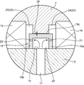
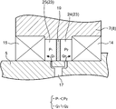
- FIG. 2 is an enlarged view of a portion surrounded by a circle II in FIG. 1. It is a partial cross section front view of the partition which comprises the said speed switching reduction gear. It is a side view of the said partition. It is the figure which showed typically the flow of the lubricating oil in the said partition vicinity. It is the expanded sectional front view corresponding to FIG. 2 which showed the principal part of the speed switching reduction gear concerning a modification.
- This embodiment illustrates the 2-speed switching reduction gear 1 provided with the input shaft 2 and the output shaft 5 as a speed switching reduction gear concerning the present invention.
- the upper side of the drawing corresponds to the input shaft side of the two-speed switching reduction gear 1
- the lower side of the drawing of FIG. 1 corresponds to the output shaft side of the two-speed switching reduction gear 1.
- 1 corresponds to the width direction of the two-speed switching reduction gear 1.
- a rotational driving force is input to the two-speed switching reduction gear 1 from the right side of the drawing, and a rotational driving force is output from the two-speed switching reduction gear 1 to the left side of the drawing.
- a rotational driving force is input to the input shaft 2 from the drive source arranged upstream on the right side of the sheet of FIG.
- the two-speed switching reduction gear 1 is a device that can be deployed in various power units.
- the two-speed switching reduction gear 1 includes an input-side low-speed gear 3 and an input-side high-speed gear 4 that are fixed to the input shaft 2, and an output-side low-speed gear that is attached to the output shaft 5.
- a large gear 7, an output-side high-speed large gear 8, and a shifter 10 are further provided.
- the two-speed switching reduction gear 1 is a constantly meshing reduction gear, and the input-side low-speed gear 3 and the output-side low-speed large gear 7 are always meshed, and the input-side high-speed gear 4 is engaged. And the output side high-speed gear 8 are always meshed with each other.
- the shifter 10 is disposed between the output-side low-speed large gear 7 and the output-side high-speed large gear 8, and alternatively the output-side low-speed large gear 7 or the output-side high-speed large gear 8.
- the rotation speed of the input shaft 2 and the rotation of the output shaft 5 can be transmitted to the output shaft 5 by connecting to the output shaft 5 from the output side large gear 7 or 8.
- the reduction ratio which is the ratio with the speed, can be switched between the reduced speed ratio, which is the first reduction ratio, and the high reduction ratio, which is the second reduction ratio.
- the input shaft 2 and the output shaft 5 pass through a casing (not shown), and gears arranged for the shafts 2 and 5 are stored in the casing.
- the rotational driving force input to the input shaft 2 from the power source is selected by the shifter 10 out of two output-side large gears in the casing, that is, the low speed large gear 7 and the high speed large gear 8. It is transmitted to the output shaft 5 while being decelerated to a predetermined speed via a large gear, and is output to the outside through the output shaft 5.
- the input shaft 2 is a long bar formed of steel or the like, and has an outer diameter that can correspond to a rotational driving force (torque) input from a power source. Install in the casing.
- the input-side low-speed gear 3 and the input-side high-speed gear 4 are fitted on the outer peripheral surface of the input shaft 2 at a predetermined interval in the axial direction.
- the input side high speed gear 4 is located. These input side gears 3 and 4 are all fixed to the input shaft 2 so as to rotate together with the input shaft 2.
- the output shaft 5 is a long bar having substantially the same shape and material as the input shaft 2, and outputs the transmitted rotational driving force to the outside.
- the output shaft 5 is arranged at a predetermined interval from the input shaft 2 so that the axis of the output shaft 5 is parallel to the axis of the input shaft 2.
- the output-side low speed large gear 7 and the output-side high speed large gear 8 are arranged on the outer peripheral surface of the output shaft 5 at a predetermined interval in the axial direction.
- the output-side low-speed large gear 7 is disposed at a position facing the input-side low-speed gear 3 so as to mesh with teeth formed on the outer peripheral surface of the input-side low-speed gear 3.
- the output-side high-speed large gear 8 is arranged at a position facing the entry-side high-speed gear 4 so as to mesh with teeth formed on the outer peripheral surface of the input-side high-speed gear 4. Yes.
- the output-side low-speed large gear 7 and the output-side high-speed large gear 8 are arranged at the same interval as the interval between the input-side low-speed gear 3 and the input-side high-speed gear 4.
- the output-side low speed large gear 7 and the output-side high speed large gear 8 are respectively rotatable on the outer peripheral surface of the output shaft 5 via a pair of first bearing 14 and second bearing 15. Installed on.
- the pair of first and second bearings 14 and 15 are arranged along the direction of the axis of the output shaft 5 indicated by a one-dot chain line in FIG. 1 and spaced apart from each other, and between the bearings 14 and 15.
- a compartment 23 that is a predetermined space is formed.
- the output-side low speed large gear 7 is a disk-shaped member, and has an outer peripheral surface on which a predetermined number of teeth are formed, an inner hole that is formed in the center and allows the output shaft 5 to pass therethrough, Have The output side low speed large gear 7 has the same tooth width as that of the input side low speed gear 3.
- Each of the first and second bearings 14 and 15 provided inside the output-side low-speed large gear 7 includes an outer race fitted in the inner hole of the output-side low-speed large gear 7, and the output shaft. 5 and an inner race that is fitted on the outer peripheral surface.
- the output-side low speed large gear 7 is attached to the output shaft 5 via the pair of first and second bearings 14 and 15 so as to be rotatable with respect to the output shaft 5. Yes. That is, the first and second bearings 14 and 15 support the output-side low-speed large gear 7 so as to allow relative rotation of the output-side low-speed large gear 7 with respect to the output shaft 5.
- the output side low speed large gear 7 has a protruding portion 9.
- the protrusion 9 protrudes in the axial direction from the side wall surface facing the high-speed large gear 8 out of both side surfaces of the output-side low-speed large gear 7 and has an annular shape surrounding the shaft center. Splines 13 that are internal teeth are formed on the peripheral surface of the protruding portion 9 facing the output shaft 5, that is, the inner peripheral surface.
- the output-side high-speed large gear 8 is a disk-like member similar to the output-side low-speed large gear 7, but has an outer diameter smaller than that of the output-side low-speed large gear 7.
- the output-side high-speed gear 8 has an inner hole formed in the center thereof and an outer peripheral surface on which a predetermined number of teeth are formed. The number of teeth is the same as that of the output-side high-speed gear 7. It is different from the number of teeth.
- the output side high speed gear 8 has the same tooth width as that of the input side high speed gear 4.
- Each of the first and second bearings 14, 15 provided inside the output-side high-speed large gear 8 includes an outer race fitted into the inner hole of the output-side high-speed large gear 8, and the output shaft.
- the output-side high-speed large gear 8 is also attached to the output shaft 5 via the first and second bearings 14 and 15 so as to be rotatable with respect to the output shaft 5. That is, the first and second bearings 14 and 15 support the output-side high-speed large gear 8 so as to allow relative rotation of the output-side high-speed large gear 8 with respect to the output shaft 5.
- the output high-speed large gear 8 also has a protruding portion 9.
- the protruding portion 9 protrudes in the axial direction from the side wall surface facing the output-side low-speed large gear 7 out of both side surfaces of the output-side high-speed large gear 8 and has an annular shape surrounding the shaft center.
- a spline 13 that is an internal tooth is formed on the peripheral surface of the protrusion 9 that faces the output shaft 5, that is, the inner peripheral surface, and the spline 13 is formed on the output-side low-speed large gear 7.
- the spline 13 has the same pitch diameter as that of the spline 13.
- the splines 13 formed on the high-speed large gear 8 and the low-speed large gear 7 are both large-diameter splines.
- a plurality of small-diameter splines 12 arranged in the circumferential direction are provided on the outer peripheral surface of a portion of the output shaft 5 located between the low speed large gear 7 and the high speed large gear 8 over the entire circumference of the output shaft 5. Is formed.
- the shifter 10 is disposed so as to surround the small-diameter spline 12 at a position radially outside the small-diameter spline 12. As shown by a solid line and a two-dot chain line in FIG. 1, the shifter 10 can move between the low speed large gear 7 and the high speed large gear 8 along the output shaft 5.
- the transmission path of the rotational driving force from the input shaft 2 to the output shaft 5 includes the low speed large gear 7, the first path for performing the deceleration at the first reduction ratio, and the high speed It is possible to switch between the second path for performing the reduction at the second reduction ratio, including the main gear 8.
- the shifter 10 has a substantially U-shaped cross section in which a central portion in the axial direction is opened radially outward in a side view, and has a ring shape surrounding the outer peripheral surface of the output shaft 5.
- the shifter 10 has an inner peripheral surface and an outer peripheral surface.
- An inner spline having a pitch diameter equal to the pitch diameter of the small-diameter spline 12 formed on the outer peripheral surface of the output shaft 5 is formed on the inner peripheral surface, and the inner spline meshes with the small-diameter spline 12. Yes. That is, the shifter 10 has an inner diameter that is substantially equal to the outer diameter of the output shaft 5.
- the outer peripheral surface of the shifter 10 has a pair of protrusions 11 located at both axial ends thereof.
- the pair of projecting portions 11 project radially outward from the intermediate portion in the axial direction so as to correspond to the projecting portion 9 of the low speed large gear 7 and the projecting portion 9 of the high speed large gear 8, respectively.
- Each projection 11 is formed with an outer spline having a pitch diameter equal to the pitch diameter of the large-diameter spline 13 formed on each large gear 7, 8. Either one of these outer splines is selectively meshed with the corresponding large gear of the output large gears 7 and 8, thereby selecting the transmission path of the rotational driving force, that is, the first reduction ratio. Selection of a reduction ratio with respect to the second reduction ratio is performed. That is, the shifter 10 has an outer diameter substantially equal to the inner diameter of the protruding portion 9.
- the small-diameter spline 12, the large-diameter spline 13, and the first and second bearings 14 and 15 require lubrication.
- a central lubricating oil passage 16 and a plurality of radial passages 17 are formed in the output shaft 5.
- the central lubricating oil passage 16 is an axial lubricating oil passage that is formed in the radial center portion of the output shaft 5 and allows the lubricating oil to flow along the axial direction of the output shaft 5.
- the central lubricating oil passage 16 has a cylindrical shape with both ends in the axial direction, one end of which forms an inlet 6 that opens at one end of the output shaft 5, and the other is The output shaft 5 is blocked inside. Lubricating oil can be fed into the central lubricating oil passage 16 from the outside through the inlet 6.
- the plurality of radial flow paths 17 are supply flow paths formed at positions corresponding to the low speed large gear 7 and the high speed large gear 8 attached to the output shaft 5, respectively.
- the lubricating oil flow path 16 branches outward in the radial direction, extends in the radial direction, and is connected to the compartment 23 for supplying lubricating oil to the bearings 14 and 15, respectively.
- Each of the radial flow paths 17 has an inner diameter that is smaller than the inner diameter of the central lubricating oil flow path 16.
- the plurality of radial flow paths 17 according to this embodiment are respectively provided from the center of the output shaft 5 to the inner peripheral surfaces of the low speed large gear 7 and the high speed large gear 8 attached to the output shaft 5. It extends straight. In the example shown in FIG.
- two radial flow paths 17 are provided for each of the low speed large gear 7 and the high speed large gear 8, and the axial centers of the two radial flow paths 17 are the same.
- the radial flow path 17 is arranged so as to be positioned on a straight line.
- each of the radial flow channels 17 is an outlet 18 that opens toward the central portion in the width direction of the inner peripheral surface of the low speed large gear 7 or the high speed large gear 8. That is, each of the radial flow paths 17 can supply lubricating oil through the outlet 18 into a compartment 23 formed between the pair of bearings 14 and 15 that are externally fitted to the output shaft 5. It is formed as follows. These radial flow paths 17 allow the lubricating oil to be supplied to the respective compartments 23 so as to branch radially outward from the outer peripheral surface of the output shaft 5. The direction and number of the radial flow paths 17 are freely set within a range that satisfies the condition that the lubricating oil can be sufficiently supplied to the compartment 23.
- the two-speed switching reduction gear further includes a plurality of partition walls 19.
- the plurality of partition walls 19 are respectively provided inside the compartments 23 formed between the first and second bearings 14 and 15 provided for the output side large gears 7 and 8, respectively, and the radial direction It is located outside the outlet 18 of the channel 17.
- the first bearing 14 is provided at a position closer to the shifter 10 than the partition wall 19 and at a position where the lubricating oil can be supplied to the shifter 10 through the first bearing 14.
- the second bearing 15 is an anti-shifter side bearing located on the opposite side of the first bearing 14 across the partition wall 19.
- the bulkhead 19 for the high speed gear 8 is similar in configuration to the bulkhead 19 for the low speed gear 7, specifically, a mirror image of the bulkhead 19 for the low speed gear 7. The detailed description thereof will be omitted.
- the partition wall 19 according to the present embodiment is provided on the outer peripheral surface of the output shaft 5 so as to protrude radially outward from the outer peripheral surface.
- the partition wall 19 includes a first compartment 24 that is a shifter side compartment adjacent to the first bearing 14 and a second compartment that is an anti-shifter side compartment adjacent to the second bearing 15.
- the partition wall 19 is a ring-shaped member having a cross section in which a central portion in the width direction is opened radially inward toward the outer peripheral surface of the output shaft 5.
- the partition wall 19 includes a first side wall 19a that stands upright from the outer peripheral surface of the output shaft 5 at a position between the outlet 18 and the first bearing 14, and the outlet 18 and the first bearing.
- the entire circumference so as to connect the second side wall 19a standing upright in the radial direction from the outer peripheral surface of the output shaft 5, and the outer peripheral portion of the first side wall 19a and the outer peripheral portion of the second side wall 19b.
- a peripheral wall 19c extending in the circumferential direction.
- the first side wall 19 a defines the first compartment 24 between the first side wall 19 a and the first bearing 14, and the second side wall 19 b is formed between the second side wall 19 b and the second bearing 15.
- a second compartment 28 is defined therebetween.
- the ring-shaped partition wall 19 is interposed between the output side large gears 7 and 8 supported on the output shaft 5 and the output shaft 5 so as to be rotatable relative to the output shaft 5. They are arranged with a gap in the radial direction.
- the ring-shaped partition wall 19 is disposed inside the output large gear 7 or 8 and outside the output shaft 5, and thus forms the compartment 23 formed between the pair of bearings 14 and 15.
- the second compartment 25 which is an anti-shifter side compartment allowing the supply of lubricating oil to the second bearing 15 located on the side opposite to the shifter 10 across the partition wall 19, Are divided into the first compartment 24 which is a shifter side compartment allowing the supply of lubricating oil to the first bearing 14 close to the shifter 10.
- the partition wall 19 defines an outer peripheral channel 20 inside thereof.
- the outer peripheral flow path 20 has a shape in which lubricating oil flowing out radially outward through the outlet 18 of the radial flow path 17 flows along the circumferential direction of the output shaft 5, that is, the outer peripheral surface of the output shaft 5.
- a ring along the line.
- a seal structure is provided that suppresses the flow of lubricating oil between the two compartments 25 so as to maintain a pressure difference between the pressure and the pressure in the first compartment 24 that is the shifter side compartment.
- the seal structure includes, for example, a clearance seal, an oil seal, and a mechanical seal.
- a plurality of first lubrication holes 21 and a plurality of second lubrication holes 22 are provided in the first side wall 19 a and the second side wall 19 b of the partition wall 19, respectively, and through the first and second lubrication holes 21, 22.
- Lubricating oil is supplied to each of the second compartment 25 that is the anti-shifter side compartment and the first compartment 24 that is the shifter side compartment.
- the shapes of the first and second lubricating holes 21 and 22 are such that the first lubricating hole 21 and the second lubricating hole 22 are in a state where the pressure in the first compartment 24 is higher than that in the second compartment 25.
- each of the first and second lubricating holes 21 and 22 is configured such that the pressure in the first compartment 24 that is the shifter side compartment is the pressure in the second compartment 25 that is the anti-shifter side compartment. It has a shape that makes it possible to supply lubricating oil at a flow rate sufficient to cause a higher state and lubricate the first bearing 14 through the first compartment 24.
- the first and second lubricating holes 21 and 22 have an inner diameter that is smaller than the inner diameter of the central lubricating oil passage 16.
- the plurality of first lubrication holes 21 and the plurality of second lubrication holes 22 are arranged in the outer peripheral direction of the output shaft 5 in each of the first side wall 19a and the second side wall 19b. It is formed at a plurality of positions lined up at equal intervals along.
- Each of the first lubricating holes 21 and each of the second lubricating holes 22 is preferably positioned so as to face each other.
- the first and second lubrication as the lubricating oil supply oil passages for the pair of bearings 14 and 15 are used.
- the pressure losses in the use holes 21 and 22 are made different from each other.
- the flow resistance of the hydraulic oil in the second lubrication hole 22 is larger than the flow resistance of the lubricant in the first lubrication hole 21. It is effective to set the shapes of both the lubricating holes 21 and 22.
- the difference between the pressure losses is, for example, that the inner diameters of the lubricating holes 21 and 22, the lengths of the lubricating holes 21 and 22, the shapes of the lubricating holes 21 and 22, and the number of the lubricating holes 21 and 22 are different from each other. Can be generated.
- the distribution of the lubricating oil supplied to each of the first and second bearings 14 and 15 will be described.
- the lubricating oil fed into the central lubricating oil flow path 16 through the inlet 6 at the end of the output shaft 5 passes through the low speed side radial flow path 17 and the low speed side partition wall 19.
- the lubricating oil needs to pass through the small-diameter spline 12, the inner spline meshing with the small-diameter spline 12, and the large-diameter spline 13 and the outer spline meshing therewith. Therefore, as schematically shown in FIG. 5, the flow rate Q2 of the lubricating oil supplied to the first compartment 24 is smaller than the flow rate Q1 of the lubricating oil supplied to the second compartment 25. There is a tendency.
- the pressure P2 in the first compartment 24 can be made higher than the pressure P1 in the second compartment 25.
- the inner diameter of the second lubrication hole 22 communicating with the second compartment 25 is set smaller than the inner diameter of the first lubrication hole 21 communicating with the first compartment 24.
- the difference between the pressure in the non-shifter side compartment 25 and the pressure in the shifter side compartment 24 can be reduced through the gap 28. There is a risk of causing a flow of lubricating oil from the shifter side compartment 24 to the non-shifter side compartment 25.
- the difference in shape (inside diameter and length) of the first and second lubricating holes 21 and 22 enables supply of lubricating oil to the bearing 14 on the shifter side, the small diameter spline 12 and the large diameter spline 13.
- the gap 28 allows the lubricating oil to move through the gap 28 due to the pressure difference, and this movement causes the shifter-side bearing 14, the small-diameter spline 12 and the large-diameter spline 13 to move. There is a possibility of reducing the amount of lubricant supplied. The same applies to the case where there is a gap between the inner peripheral surface of the first and second side walls 19a, 19b and the outer peripheral surface of the output shaft 5.
- the gap 28 between the outer peripheral surface of the peripheral wall 19c of the partition wall 19 and the inner peripheral surface of the low-speed large gear 7 is reduced so that the first compartment 24 through the gap 28 can be It is preferable to prevent or suppress the flow of the lubricating oil to the second compartment 25.
- the inner peripheral surface of the first and second side walls 19a, 19b of the partition wall 19 or the outer peripheral surface (clearance seal portion) of the portion of the output shaft 5 located between the pair of left and right bearings 14, 15 And at least the outer peripheral surface of the peripheral wall 19c of the partition wall 19 or the inner peripheral surface (clearance seal portion) of the portion located between the first and second bearings 14 and 15 of the output large gears 7 and 8.
- a film having lubricity for example, copper plating
- a film having lubricity for example, copper plating
- each of the partition wall 19 and the output shaft 5 has a contact surface that can make contact with each other while relatively rotating, that is, a contact surface constituting a clearance seal portion, at least the contact surface.
- a film having the lubricity is applied on one side.
- the partition wall 19 and the output side large gears 7 and 8 have contact surfaces that can contact each other while rotating relative to each other, that is, contact surfaces constituting a clearance seal portion, the contact It is preferable that at least one of the surfaces is provided with a film having the lubricity.
- the lubricating coating is formed by the contact between the first and second side walls 19a and 19b of the partition wall 19 and the output shaft 5 in the clearance seal portion, or the peripheral wall 19c of the partition wall 19 and each output-side large gear. Regardless of the contact with 7, 8, the self-lubricating property of copper or the like constituting the coating can minimize the damage to the members of the partition wall 19, the output shaft 5, and the large gears 7, 8.
- the diameter of the second lubricating hole 22 on the anti-shifter side is smaller than the diameter of the first lubricating hole 21 on the shifter side. It is possible to obtain a similar effect.
- the two-speed switching reduction gear 1 gives the pressure of the lubricating oil supplied to the first and second bearings 14 and 15 aligned in the axial direction of the output shaft 5 to each other, and The movement of the lubricating oil due to the pressure difference in the second compartment 25, which is the anti-shifter side compartment, and the first compartment 24, which is the shifter side compartment, is suppressed, and the conventional structure makes it difficult to sufficiently supply the lubricating oil. Further, by setting the first compartment 24 adjacent to the first bearing 14 to a high pressure, the lubricating oil is sufficiently supplied not only to the first and second bearings 14 and 15 but also to the small diameter spline 12 and the large diameter spline 13.
- the flow passage areas of the first and second lubricating holes 21 and 22 are preferably smaller than the flow passage areas of the central lubricating flow passage 16 and the radial flow passage 17. The fluid throttling effect thereby prevents the lubricating oil from intensively flowing to only one location, and evenly supplies the lubricating oil to the pair of left and right bearings 14, 15, the small diameter spline 12, and the large diameter spline 13. Enable.
- the lubricating oil flow path formed inside the output shaft 5 has a plurality of radial flow paths 17 communicating with a common central lubricating oil flow path 16 and branched radially outward from the central lubricating oil flow path 16. Therefore, a large amount of lubricating oil can be supplied to the pair of bearings 14, 15, the small-diameter spline 12 and the large-diameter spline 13 by utilizing the centrifugal force acting on the lubricating oil by the rotation of the output shaft 5. .
- the two-speed switching reduction gear 1 according to the modified example is different from the two-speed switching reduction gear 1 according to the embodiment, that is, shown in FIGS. 1 and 2 only in the following points (a) and (b). .
- each outlet 18 of the plurality of radial flow paths 17 is located closer to the axial center than the outer peripheral surface of the output shaft 5, specifically, A specific portion of the outer peripheral surface of the output shaft 5 that is positioned between the pair of bearings 14 and 15 is positioned more radially inward than the other portions to form a step (that is, a small diameter) outer periphery.
- the outflow port 18 is located on the small-diameter outer peripheral surface 5.
- the configuration excluding the differences (a) and (b) is the same as the configuration of the two-speed switching reducer 1 according to the above embodiment, and therefore the description thereof is omitted. Is omitted.
- the oil seal 26 is a member for constructing a seal structure that suppresses the outflow of lubricating oil from the first compartment 24 to the second compartment 25 through the gap 28, and the outer peripheral surface of the peripheral wall 19 c of the partition wall 19. And the clearance 28 between the inner peripheral surfaces of the output side large gears 7 and 8 are provided at positions close to the shifter side compartment 24.
- the oil seal 26 is formed of an elastic body such as hard rubber, for example, and extends radially outward from the inner peripheral surface of the output large gears 7 and 8 toward the radially inner side from the base 26a. Accordingly, the seal portion 26b is inclined and extended toward the bearing 14, and the seal portion 26b has a tip portion that can be brought into close contact with the outer peripheral surface of the peripheral wall 19c.
- the oil seal 26 is provided in the gap 28, whereby first and second lubricating oils provided on the first side wall 19 a near the shifter 10 and the second side wall 19 b on the opposite side of the shifter 10 in the partition wall 19, respectively.
- the movement of the lubricating oil through the gap 28 between the outer peripheral surface of the partition wall 19 and the large gears 7 and 8 due to the pressure difference of the lubricating oil caused by the difference in the shapes of the holes 21 and 22 is prevented or suppressed.
- more lubricating oil can be supplied to the bearing 14, the small-diameter spline 12, and the large-diameter spline 13 close to the shifter 10.
- the shape and material of the oil seal 26 are such that the portion of the gap 28 that communicates with the second compartment 25 and the portion of the gap 28 that communicates with the first compartment 24 are reliably separated from each other. As long as the condition of suppressing the movement of the lubricating oil between 25 and 24 is satisfied, it is appropriately selected.
- the small-diameter outer peripheral surface 5 a surrounding the outlet 18 and the other portions are different in level, which enlarges the outer peripheral flow path 20 formed inside the partition wall 19. This makes it possible to distribute more lubricating oil.
- embodiment disclosed this time is an illustration and restrictive at no points.
- matters that are not explicitly disclosed, for example, operating conditions and operating conditions, various parameters, dimensions, weights, volumes, and the like of a component deviate from a range that a person skilled in the art normally performs. Instead, values that can be easily assumed by those skilled in the art are employed.
- the technology of the present invention includes a plurality of output side gears, and a shifter for selecting an output side gear used for reducing the rotational driving force to a predetermined speed among the plurality of output side gears. It can be widely applied to speed switching reducers (for example, 2-speed or 3-speed switching reducers).
- a speed-switching speed reducer capable of supplying appropriate lubricating oil to a bearing that supports an output-side gear that transmits rotational driving force.
- the speed switching reducer includes an input shaft, an output shaft that outputs the rotational driving force transmitted from the input shaft to the outside, the rotational driving force transmitted from the input shaft to the output shaft, and the input shaft.
- a plurality of output-side gears attached to the output shaft corresponding to the reduction ratio so as to be able to switch a reduction ratio that is a ratio between a rotation speed and a rotation speed of the output shaft; and the plurality of output sides A shifter that selectively connects the gear to the output shaft to transmit the rotational driving force from the output shaft gear to the output shaft, a first bearing provided for each of the plurality of output side gears, and a first bearing 2 bearings, which are arranged on the outer peripheral surface of the output shaft and are provided between the first bearing and the second bearing for supplying lubricating oil to the first bearing and the second bearing.
- Each other in the axial direction of the output shaft so as to form A first bearing and a second bearing that support the output side gear so as to allow relative rotation of the output side gear with respect to the output shaft, and the inner side of each of the plurality of output side gears.
- a plurality of partition walls provided in the compartment so as to protrude radially outward from the outer peripheral surface of the output shaft.
- the first bearing is a shifter side bearing provided at a position closer to the shifter than the partition wall and capable of supplying the lubricant to the shifter through the first bearing
- the second bearing includes the partition wall. It is an anti-shifter side bearing located on the opposite side to the first bearing.
- the output shaft extends along the axial direction inside the output shaft, communicates with the axial lubricating oil flow path through which the lubricating oil flows, and the axial lubricating oil flow path.
- a plurality of supply passages extending radially outward from the directional lubricating oil passage and communicating with the compartment.
- the partition divides the compartment into a first compartment adjacent to the first bearing and a second compartment adjacent to the second bearing, and the pressure of the lubricating oil in the first compartment is the first compartment. Allow supply of lubricant oil from the supply oil passage to the first compartment and supply of lubricant oil from the supply oil passage to the second compartment so as to be higher than the pressure of the lubricant oil in the two compartments. To do.
- the partition wall divides a compartment formed between a pair of bearings rotatably supporting the output side gear into a first compartment and a second compartment, and It is possible to supply an appropriate lubricating oil to any of the bearings.
- the partition is disposed so as to be relatively rotatable with respect to either the output shaft gear or the output shaft, and the speed switching reducer is disposed in the gap and passes through the gap. It is preferable to further include a seal structure that suppresses the flow of lubricating oil between the first compartment and the second compartment. The seal structure further increases the independence of the pressure in the first compartment and the pressure in the second compartment, and enables more appropriate supply of lubricating oil.
- the partition includes a first side wall defining the first compartment with the first bearing and a second side wall defining the second compartment with the second bearing.
- the first side wall is provided with a first lubricating hole that allows supply of lubricating oil from the supply flow path to the first compartment
- the second side wall is provided with the first flow path from the supply flow path to the second compartment.
- a second lubricating hole that allows supply of the lubricating oil is provided, and the shape of the first lubricating hole and the second lubricating hole is such that the flow resistance of the lubricating oil in the second lubricating hole is the first lubricating hole. It is good to set so that it may become larger than the distribution
- This structure makes it possible to ensure a difference between the pressure in the first compartment and the pressure in the second compartment.
- the partition wall and the output shaft have contact surfaces that contact each other while rotating relative to each other, it is preferable that at least one of the contact surfaces is provided with a film having lubricity.
- the partition wall and the output side gear have contact surfaces that contact each other while relatively rotating, it is preferable that at least one of the contact surfaces is provided with a film having lubricity. In any of the above cases, the lubricity of the coating effectively suppresses wear damage of the contact surfaces due to contact between the contact surfaces.
- first lubricating hole and the second lubricating hole are respectively provided at a plurality of positions aligned along the outer peripheral direction of the output shaft. This allows the lubricating oil to be supplied with high uniformity in the circumferential direction to the first and second bearings.
- the lubrication hole has a flow path area smaller than the flow area of the axial lubricating oil flow path and the supply flow paths.
- the throttling effect of the lubricating holes having such a small flow path area suppresses uneven distribution of the lubricating oil flow, and enables the lubricating oil to be supplied to the bearing and the shifter with high uniformity.
- the flow passage area of the second lubricating hole is smaller than the flow passage area of the first lubricating hole. This makes it possible to ensure that the pressure of the lubricating oil in the first compartment is higher than the pressure of the lubricating oil in the first compartment.
- the plurality of supply channels are arranged so as to branch radially outward from the axial direction lubricating oil channel and supply the lubricating oil to the compartment. This makes it possible to promote the supply of the lubricating oil to the bearing and the shifter by effectively applying the centrifugal force generated by the rotation of the output shaft to the lubricating oil.
Abstract
Description
Claims (9)
- 減速比を切換えることが可能な速度切換減速機であって、
入力軸と、
前記入力軸から伝達される回転駆動力を外部に出力する出力軸と、
前記入力軸から前記出力軸に前記回転駆動力を伝達するとともに前記入力軸の回転速度と前記出力軸の回転速度との比である減速比を切換えることが可能となるように当該減速比に対応して前記出力軸に取付けられる複数の出力側歯車と、
前記複数の出力側歯車を択一的に出力軸に連結して当該出力軸歯車から当該出力軸への回転駆動力の伝達を可能にするシフターと、
前記複数の出力側歯車のそれぞれについて設けられる第1軸受及び第2軸受であって、前記出力軸の外周面上に配置され、当該第1軸受と当該第2軸受との間に当該第1軸受及び当該第2軸受への潤滑油の供給のための隔室を形成するように前記出力軸の軸心方向に互いに間隔をおいて並び、前記出力軸に対する前記出力側歯車の相対回転を許容するように当該出力側歯車を支持する第1軸受及び第2軸受と、
前記複数の出力側歯車のそれぞれの内側において前記出力軸の外周面から径方向外向きに突出するように前記隔室内に設けられる複数の隔壁と、を備え、
前記第1軸受は前記隔壁よりも前記シフターに近い位置であって当該第1軸受を通じて前記シフターに前記潤滑油が供給可能な位置に設けられるシフター側軸受であり、前記第2軸受は前記隔壁を挟んで前記第1軸受と反対側に位置する反シフター側軸受であり、
前記出力軸は、当該出力軸の内部においてその軸心方向に沿って延び、潤滑油を流通させる軸心方向潤滑油流路と、当該軸心方向潤滑油流路と連通し、且つ当該軸心方向潤滑油油路から径方向外向きに延びて前記隔室に連通する複数の供給流路と、を有し、
前記隔壁は、前記隔室を前記第1軸受に隣接する第1隔室と前記第2軸受に隣接する第2隔室とに分割し、且つ当該第1隔室内の潤滑油の圧力が当該第2隔室内の潤滑油の圧力よりも高くなるように前記供給油路から前記第1隔室内への潤滑油の供給と前記供給油路から前記第2隔室内への潤滑油の供給とを許容する、速度切換減速機。 - 前記隔壁は、前記出力側歯車及び前記出力軸のいずれか一方と相対的に回転可能となるように当該一方と当該隔壁との間に隙間をおいて配置され、前記速度切換減速機は、前記隙間に配置されて当該隙間を通じての前記第1隔室と前記第2隔室との間の潤滑油の流通を抑止するシール構造をさらに備える、請求項1に記載の速度切換減速機。
- 前記隔壁は、前記第1軸受との間に前記第1隔室を画定する第1側壁及び前記第2軸受との間に前記第2隔室を画定する第2側壁を含み、前記第1側壁に前記供給流路から前記第1隔室への潤滑油の供給を許容する第1潤滑用孔が設けられ、前記第2側壁に前記供給流路から前記第2隔室への潤滑油の供給を許容する第2潤滑用孔が設けられ、前記第1潤滑用孔及び前記第2潤滑用孔の形状は、当該第2潤滑用孔における潤滑油の流通抵抗が当該第1潤滑用孔における潤滑油の流通抵抗よりも大きくなるように設定されている、請求項1又は2に記載の速度切換減速機。
- 前記隔壁及び前記出力軸は互いに相対回転しながら接触する接触面を有していて当該接触面の少なくとも一方に潤滑性を備えた被膜が施されている、請求項1記載の速度切換減速機。
- 前記隔壁及び前記出力側歯車は互いに相対回転しながら接触する接触面を有していて当該接触面の少なくとも一方に潤滑性を備えた被膜が施されている、請求項1記載の速度切換減速機。
- 前記第1潤滑用孔及び第2潤滑用孔は、前記出力軸の外周方向に沿って並ぶ複数の位置にそれぞれ設けられている、請求項3に記載の速度切換減速機。
- 前記第1潤滑用孔及び前記第2潤滑用孔は、前記軸心方向潤滑油流路及び前記各供給流路の流路面積より小さい流路面積を有する、請求項3に記載の速度切換減速機。
- 前記第2潤滑用孔の流路面積が前記第1潤滑用孔の流路面積よりも小さい、請求項6に記載の速度切換減速機。
- 前記複数の供給流路は、前記軸心方向潤滑油流路から径方向外向きに枝分かれして前記隔室に潤滑油を供給するように配置されている、請求項1記載の速度切換減速機。
Priority Applications (4)
| Application Number | Priority Date | Filing Date | Title |
|---|---|---|---|
| US16/079,048 US10871219B2 (en) | 2016-02-26 | 2017-02-10 | Speed-switchable reduction gear |
| EP17756246.9A EP3404293B1 (en) | 2016-02-26 | 2017-02-10 | Speed-switchable reduction gear |
| CN201780012538.6A CN108700181B (zh) | 2016-02-26 | 2017-02-10 | 可切换速度的减速机 |
| KR1020187024471A KR102035544B1 (ko) | 2016-02-26 | 2017-02-10 | 속도 전환이 가능한 감속기 |
Applications Claiming Priority (2)
| Application Number | Priority Date | Filing Date | Title |
|---|---|---|---|
| JP2016-035688 | 2016-02-26 | ||
| JP2016035688A JP6556644B2 (ja) | 2016-02-26 | 2016-02-26 | 速度切換減速機 |
Publications (1)
| Publication Number | Publication Date |
|---|---|
| WO2017145805A1 true WO2017145805A1 (ja) | 2017-08-31 |
Family
ID=59686105
Family Applications (1)
| Application Number | Title | Priority Date | Filing Date |
|---|---|---|---|
| PCT/JP2017/004899 WO2017145805A1 (ja) | 2016-02-26 | 2017-02-10 | 速度切換が可能な減速機 |
Country Status (7)
| Country | Link |
|---|---|
| US (1) | US10871219B2 (ja) |
| EP (1) | EP3404293B1 (ja) |
| JP (1) | JP6556644B2 (ja) |
| KR (1) | KR102035544B1 (ja) |
| CN (1) | CN108700181B (ja) |
| TW (1) | TWI644039B (ja) |
| WO (1) | WO2017145805A1 (ja) |
Families Citing this family (36)
| Publication number | Priority date | Publication date | Assignee | Title |
|---|---|---|---|---|
| US11624326B2 (en) | 2017-05-21 | 2023-04-11 | Bj Energy Solutions, Llc | Methods and systems for supplying fuel to gas turbine engines |
| JP7131220B2 (ja) * | 2018-09-10 | 2022-09-06 | トヨタ自動車株式会社 | 車両用動力伝達装置 |
| DE102019200552A1 (de) * | 2019-01-17 | 2020-07-23 | Zf Friedrichshafen Ag | Bauteilanordnung für ein Kraftfahrzeug |
| US11560845B2 (en) | 2019-05-15 | 2023-01-24 | Bj Energy Solutions, Llc | Mobile gas turbine inlet air conditioning system and associated methods |
| CA3197583A1 (en) | 2019-09-13 | 2021-03-13 | Bj Energy Solutions, Llc | Fuel, communications, and power connection systems and related methods |
| US11015594B2 (en) | 2019-09-13 | 2021-05-25 | Bj Energy Solutions, Llc | Systems and method for use of single mass flywheel alongside torsional vibration damper assembly for single acting reciprocating pump |
| CA3092829C (en) | 2019-09-13 | 2023-08-15 | Bj Energy Solutions, Llc | Methods and systems for supplying fuel to gas turbine engines |
| US10961914B1 (en) | 2019-09-13 | 2021-03-30 | BJ Energy Solutions, LLC Houston | Turbine engine exhaust duct system and methods for noise dampening and attenuation |
| US10815764B1 (en) | 2019-09-13 | 2020-10-27 | Bj Energy Solutions, Llc | Methods and systems for operating a fleet of pumps |
| CA3092865C (en) | 2019-09-13 | 2023-07-04 | Bj Energy Solutions, Llc | Power sources and transmission networks for auxiliary equipment onboard hydraulic fracturing units and associated methods |
| US10895202B1 (en) | 2019-09-13 | 2021-01-19 | Bj Energy Solutions, Llc | Direct drive unit removal system and associated methods |
| US11555756B2 (en) | 2019-09-13 | 2023-01-17 | Bj Energy Solutions, Llc | Fuel, communications, and power connection systems and related methods |
| US11002189B2 (en) | 2019-09-13 | 2021-05-11 | Bj Energy Solutions, Llc | Mobile gas turbine inlet air conditioning system and associated methods |
| JP2021156359A (ja) * | 2020-03-27 | 2021-10-07 | いすゞ自動車株式会社 | 潤滑構造 |
| US11708829B2 (en) | 2020-05-12 | 2023-07-25 | Bj Energy Solutions, Llc | Cover for fluid systems and related methods |
| US10968837B1 (en) | 2020-05-14 | 2021-04-06 | Bj Energy Solutions, Llc | Systems and methods utilizing turbine compressor discharge for hydrostatic manifold purge |
| US11428165B2 (en) | 2020-05-15 | 2022-08-30 | Bj Energy Solutions, Llc | Onboard heater of auxiliary systems using exhaust gases and associated methods |
| US11208880B2 (en) | 2020-05-28 | 2021-12-28 | Bj Energy Solutions, Llc | Bi-fuel reciprocating engine to power direct drive turbine fracturing pumps onboard auxiliary systems and related methods |
| US11208953B1 (en) | 2020-06-05 | 2021-12-28 | Bj Energy Solutions, Llc | Systems and methods to enhance intake air flow to a gas turbine engine of a hydraulic fracturing unit |
| US11109508B1 (en) | 2020-06-05 | 2021-08-31 | Bj Energy Solutions, Llc | Enclosure assembly for enhanced cooling of direct drive unit and related methods |
| US11111768B1 (en) | 2020-06-09 | 2021-09-07 | Bj Energy Solutions, Llc | Drive equipment and methods for mobile fracturing transportation platforms |
| US10954770B1 (en) | 2020-06-09 | 2021-03-23 | Bj Energy Solutions, Llc | Systems and methods for exchanging fracturing components of a hydraulic fracturing unit |
| US11066915B1 (en) | 2020-06-09 | 2021-07-20 | Bj Energy Solutions, Llc | Methods for detection and mitigation of well screen out |
| US11028677B1 (en) | 2020-06-22 | 2021-06-08 | Bj Energy Solutions, Llc | Stage profiles for operations of hydraulic systems and associated methods |
| US11939853B2 (en) | 2020-06-22 | 2024-03-26 | Bj Energy Solutions, Llc | Systems and methods providing a configurable staged rate increase function to operate hydraulic fracturing units |
| US11125066B1 (en) | 2020-06-22 | 2021-09-21 | Bj Energy Solutions, Llc | Systems and methods to operate a dual-shaft gas turbine engine for hydraulic fracturing |
| US11933153B2 (en) | 2020-06-22 | 2024-03-19 | Bj Energy Solutions, Llc | Systems and methods to operate hydraulic fracturing units using automatic flow rate and/or pressure control |
| US11466680B2 (en) | 2020-06-23 | 2022-10-11 | Bj Energy Solutions, Llc | Systems and methods of utilization of a hydraulic fracturing unit profile to operate hydraulic fracturing units |
| US11473413B2 (en) | 2020-06-23 | 2022-10-18 | Bj Energy Solutions, Llc | Systems and methods to autonomously operate hydraulic fracturing units |
| US11220895B1 (en) | 2020-06-24 | 2022-01-11 | Bj Energy Solutions, Llc | Automated diagnostics of electronic instrumentation in a system for fracturing a well and associated methods |
| US11149533B1 (en) | 2020-06-24 | 2021-10-19 | Bj Energy Solutions, Llc | Systems to monitor, detect, and/or intervene relative to cavitation and pulsation events during a hydraulic fracturing operation |
| US11193360B1 (en) | 2020-07-17 | 2021-12-07 | Bj Energy Solutions, Llc | Methods, systems, and devices to enhance fracturing fluid delivery to subsurface formations during high-pressure fracturing operations |
| DE102020209633A1 (de) * | 2020-07-30 | 2022-02-03 | Mahle International Gmbh | Verfahren zur Herstellung eines Spritzkanals in einem Wellenrohr |
| CN111998010B (zh) * | 2020-09-15 | 2022-04-01 | 嘉兴爱克斯机械技术有限公司 | 用于盘车装置自动脱离齿式离合器的新型摩擦块联动机构 |
| CN112984091B (zh) * | 2021-03-05 | 2022-08-30 | 中国航发沈阳发动机研究所 | 一种航空发动机轴间轴承的轴心供油结构 |
| US11639654B2 (en) | 2021-05-24 | 2023-05-02 | Bj Energy Solutions, Llc | Hydraulic fracturing pumps to enhance flow of fracturing fluid into wellheads and related methods |
Citations (4)
| Publication number | Priority date | Publication date | Assignee | Title |
|---|---|---|---|---|
| JPS6349053U (ja) * | 1986-09-18 | 1988-04-02 | ||
| JPS6443263U (ja) * | 1987-09-10 | 1989-03-15 | ||
| JPH0276252U (ja) * | 1988-11-30 | 1990-06-12 | ||
| JPH10110791A (ja) * | 1996-10-04 | 1998-04-28 | Kobe Steel Ltd | 2段切換減速機 |
Family Cites Families (15)
| Publication number | Priority date | Publication date | Assignee | Title |
|---|---|---|---|---|
| US4368802A (en) * | 1980-07-03 | 1983-01-18 | Rockwell International Corporation | Pressurized lubrication system |
| JPS62278340A (ja) * | 1986-05-26 | 1987-12-03 | Mazda Motor Corp | 歯車式変速機の同期装置 |
| JPH11118029A (ja) * | 1997-10-13 | 1999-04-30 | Daihatsu Motor Co Ltd | シフトフォークの潤滑構造 |
| KR100309337B1 (ko) * | 1997-12-24 | 2001-12-28 | 이계안 | 수동변속기의슬러지제거형윤활구조 |
| US6929402B1 (en) * | 2002-04-11 | 2005-08-16 | Morgan Construction Company | Journal bearing and thrust pad assembly |
| JP2004076810A (ja) * | 2002-08-12 | 2004-03-11 | Yanagawa Seiki Co Ltd | トランスミッションの潤滑構造 |
| DE102007045368A1 (de) * | 2007-09-22 | 2009-04-02 | Zf Friedrichshafen Ag | Verfahren und Vorrichtung zur Beölung der Axialanläufe von auf einer Welle angeordneten Losrädern |
| JP4930453B2 (ja) * | 2008-05-12 | 2012-05-16 | トヨタ自動車株式会社 | 回転軸の軸受潤滑構造 |
| CN201215177Y (zh) * | 2008-06-06 | 2009-04-01 | 上海汽车集团股份有限公司 | 双中间轴式手动变速器的润滑结构 |
| CN201875108U (zh) * | 2010-11-15 | 2011-06-22 | 南京高特齿轮箱制造有限公司 | 高速换挡工业齿轮箱的润滑装置 |
| US9228653B2 (en) * | 2013-08-09 | 2016-01-05 | Schaeffler Technologies AG & Co. KG | Idler sprocket lubrication assembly and method |
| US9587731B2 (en) * | 2013-08-27 | 2017-03-07 | Kawasaki Jukogyo Kabushiki Kaisha | Lubricating apparatus for rotating shaft |
| CN203431147U (zh) * | 2013-09-10 | 2014-02-12 | 天津拖拉机制造有限公司 | 拖拉机变速箱内置润滑系统装置 |
| CN103671758A (zh) * | 2013-12-16 | 2014-03-26 | 陕西法士特齿轮有限责任公司 | 一种六档汽车变速器 |
| US9822869B1 (en) * | 2016-08-25 | 2017-11-21 | Schaeffler Technologies AG & Co. KG | Speed regulated shaft oil flow controller |
-
2016
- 2016-02-26 JP JP2016035688A patent/JP6556644B2/ja active Active
-
2017
- 2017-02-10 CN CN201780012538.6A patent/CN108700181B/zh active Active
- 2017-02-10 EP EP17756246.9A patent/EP3404293B1/en active Active
- 2017-02-10 KR KR1020187024471A patent/KR102035544B1/ko active IP Right Grant
- 2017-02-10 US US16/079,048 patent/US10871219B2/en active Active
- 2017-02-10 WO PCT/JP2017/004899 patent/WO2017145805A1/ja active Application Filing
- 2017-02-23 TW TW106106222A patent/TWI644039B/zh active
Patent Citations (4)
| Publication number | Priority date | Publication date | Assignee | Title |
|---|---|---|---|---|
| JPS6349053U (ja) * | 1986-09-18 | 1988-04-02 | ||
| JPS6443263U (ja) * | 1987-09-10 | 1989-03-15 | ||
| JPH0276252U (ja) * | 1988-11-30 | 1990-06-12 | ||
| JPH10110791A (ja) * | 1996-10-04 | 1998-04-28 | Kobe Steel Ltd | 2段切換減速機 |
Also Published As
| Publication number | Publication date |
|---|---|
| EP3404293A4 (en) | 2019-07-24 |
| EP3404293A1 (en) | 2018-11-21 |
| KR102035544B1 (ko) | 2019-10-24 |
| US20190048993A1 (en) | 2019-02-14 |
| TWI644039B (zh) | 2018-12-11 |
| JP6556644B2 (ja) | 2019-08-07 |
| EP3404293B1 (en) | 2021-04-07 |
| US10871219B2 (en) | 2020-12-22 |
| TW201741575A (zh) | 2017-12-01 |
| JP2017150636A (ja) | 2017-08-31 |
| KR20180102187A (ko) | 2018-09-14 |
| CN108700181A (zh) | 2018-10-23 |
| CN108700181B (zh) | 2021-05-04 |
Similar Documents
| Publication | Publication Date | Title |
|---|---|---|
| WO2017145805A1 (ja) | 速度切換が可能な減速機 | |
| JP5929527B2 (ja) | 変速機の潤滑構造 | |
| JP4998185B2 (ja) | 自動変速機 | |
| JP4642514B2 (ja) | プラネタリギヤの潤滑装置 | |
| US8523725B2 (en) | Lubricating structure of speed change mechanism | |
| CN108930730B (zh) | 变速器的制动器装置 | |
| JP2007032624A (ja) | 車両用自動変速機 | |
| JP6199169B2 (ja) | 車両用駆動装置 | |
| US11236650B2 (en) | Oil supply structure of transmission | |
| CN103703283B (zh) | 自动变速器的润滑装置 | |
| JP2016099000A (ja) | オイルポンプ | |
| JP2007016931A (ja) | スラストワッシャの潤滑油路構造 | |
| JP6705855B2 (ja) | 変速機の潤滑油供給構造 | |
| JP2008089078A (ja) | ピニオンシャフト及び自動変速機 | |
| JP2006105217A (ja) | 車両用ベルト式無段変速機の潤滑装置 | |
| JP6201923B2 (ja) | 変速機の潤滑装置 | |
| JP2006009994A (ja) | 無段変速装置 | |
| JP6493346B2 (ja) | 車両用無段変速機 | |
| JP6296924B2 (ja) | 動力分割式無段変速機 | |
| JP2006132553A (ja) | 前後進切替装置の潤滑構造 | |
| JP2018062963A (ja) | 車両用無段変速機 | |
| JP2015209878A (ja) | 車両用ベルト式無段変速機 | |
| JP2016033375A (ja) | フィードパイプ取り付け構造 | |
| JP2005291431A (ja) | 潤滑油を対向供給されるディスク/ローラ型無段変速機 |
Legal Events
| Date | Code | Title | Description |
|---|---|---|---|
| WWE | Wipo information: entry into national phase |
Ref document number: 2017756246 Country of ref document: EP |
|
| ENP | Entry into the national phase |
Ref document number: 20187024471 Country of ref document: KR Kind code of ref document: A |
|
| WWE | Wipo information: entry into national phase |
Ref document number: 1020187024471 Country of ref document: KR |
|
| NENP | Non-entry into the national phase |
Ref country code: DE |
|
| ENP | Entry into the national phase |
Ref document number: 2017756246 Country of ref document: EP Effective date: 20180813 |