WO2017094735A1 - 熱転写シートまたは受像シート用ボビン、ボビンとシートの組合体および熱転写プリンタ - Google Patents
熱転写シートまたは受像シート用ボビン、ボビンとシートの組合体および熱転写プリンタ Download PDFInfo
- Publication number
- WO2017094735A1 WO2017094735A1 PCT/JP2016/085450 JP2016085450W WO2017094735A1 WO 2017094735 A1 WO2017094735 A1 WO 2017094735A1 JP 2016085450 W JP2016085450 W JP 2016085450W WO 2017094735 A1 WO2017094735 A1 WO 2017094735A1
- Authority
- WO
- WIPO (PCT)
- Prior art keywords
- bobbin
- sheet
- thermal transfer
- image receiving
- main body
- Prior art date
- Legal status (The legal status is an assumption and is not a legal conclusion. Google has not performed a legal analysis and makes no representation as to the accuracy of the status listed.)
- Ceased
Links
Images

Classifications
-
- B—PERFORMING OPERATIONS; TRANSPORTING
- B41—PRINTING; LINING MACHINES; TYPEWRITERS; STAMPS
- B41J—TYPEWRITERS; SELECTIVE PRINTING MECHANISMS, i.e. MECHANISMS PRINTING OTHERWISE THAN FROM A FORME; CORRECTION OF TYPOGRAPHICAL ERRORS
- B41J2/00—Typewriters or selective printing mechanisms characterised by the printing or marking process for which they are designed
- B41J2/315—Typewriters or selective printing mechanisms characterised by the printing or marking process for which they are designed characterised by selective application of heat to a heat sensitive printing or impression-transfer material
- B41J2/32—Typewriters or selective printing mechanisms characterised by the printing or marking process for which they are designed characterised by selective application of heat to a heat sensitive printing or impression-transfer material using thermal heads
- B41J2/325—Typewriters or selective printing mechanisms characterised by the printing or marking process for which they are designed characterised by selective application of heat to a heat sensitive printing or impression-transfer material using thermal heads by selective transfer of ink from ink carrier, e.g. from ink ribbon or sheet
-
- B—PERFORMING OPERATIONS; TRANSPORTING
- B41—PRINTING; LINING MACHINES; TYPEWRITERS; STAMPS
- B41J—TYPEWRITERS; SELECTIVE PRINTING MECHANISMS, i.e. MECHANISMS PRINTING OTHERWISE THAN FROM A FORME; CORRECTION OF TYPOGRAPHICAL ERRORS
- B41J17/00—Mechanisms for manipulating page-width impression-transfer material, e.g. carbon paper
- B41J17/22—Supply arrangements for webs of impression-transfer material
- B41J17/24—Webs supplied from reels or spools attached to the machine
-
- B—PERFORMING OPERATIONS; TRANSPORTING
- B41—PRINTING; LINING MACHINES; TYPEWRITERS; STAMPS
- B41J—TYPEWRITERS; SELECTIVE PRINTING MECHANISMS, i.e. MECHANISMS PRINTING OTHERWISE THAN FROM A FORME; CORRECTION OF TYPOGRAPHICAL ERRORS
- B41J17/00—Mechanisms for manipulating page-width impression-transfer material, e.g. carbon paper
- B41J17/32—Detachable carriers or holders for impression-transfer material mechanism
-
- B—PERFORMING OPERATIONS; TRANSPORTING
- B41—PRINTING; LINING MACHINES; TYPEWRITERS; STAMPS
- B41J—TYPEWRITERS; SELECTIVE PRINTING MECHANISMS, i.e. MECHANISMS PRINTING OTHERWISE THAN FROM A FORME; CORRECTION OF TYPOGRAPHICAL ERRORS
- B41J32/00—Ink-ribbon cartridges
-
- B—PERFORMING OPERATIONS; TRANSPORTING
- B41—PRINTING; LINING MACHINES; TYPEWRITERS; STAMPS
- B41J—TYPEWRITERS; SELECTIVE PRINTING MECHANISMS, i.e. MECHANISMS PRINTING OTHERWISE THAN FROM A FORME; CORRECTION OF TYPOGRAPHICAL ERRORS
- B41J33/00—Apparatus or arrangements for feeding ink ribbons or like character-size impression-transfer material
- B41J33/14—Ribbon-feed devices or mechanisms
- B41J33/16—Ribbon-feed devices or mechanisms with drive applied to spool or spool spindle
- B41J33/22—Ribbon-feed devices or mechanisms with drive applied to spool or spool spindle by gears or pulleys
-
- B—PERFORMING OPERATIONS; TRANSPORTING
- B65—CONVEYING; PACKING; STORING; HANDLING THIN OR FILAMENTARY MATERIAL
- B65H—HANDLING THIN OR FILAMENTARY MATERIAL, e.g. SHEETS, WEBS, CABLES
- B65H75/00—Storing webs, tapes, or filamentary material, e.g. on reels
- B65H75/02—Cores, formers, supports, or holders for coiled, wound, or folded material, e.g. reels, spindles, bobbins, cop tubes, cans, mandrels or chucks
- B65H75/04—Kinds or types
- B65H75/08—Kinds or types of circular or polygonal cross-section
- B65H75/10—Kinds or types of circular or polygonal cross-section without flanges, e.g. cop tubes
-
- B—PERFORMING OPERATIONS; TRANSPORTING
- B65—CONVEYING; PACKING; STORING; HANDLING THIN OR FILAMENTARY MATERIAL
- B65H—HANDLING THIN OR FILAMENTARY MATERIAL, e.g. SHEETS, WEBS, CABLES
- B65H75/00—Storing webs, tapes, or filamentary material, e.g. on reels
- B65H75/02—Cores, formers, supports, or holders for coiled, wound, or folded material, e.g. reels, spindles, bobbins, cop tubes, cans, mandrels or chucks
- B65H75/18—Constructional details
- B65H75/30—Arrangements to facilitate driving or braking
-
- B—PERFORMING OPERATIONS; TRANSPORTING
- B41—PRINTING; LINING MACHINES; TYPEWRITERS; STAMPS
- B41J—TYPEWRITERS; SELECTIVE PRINTING MECHANISMS, i.e. MECHANISMS PRINTING OTHERWISE THAN FROM A FORME; CORRECTION OF TYPOGRAPHICAL ERRORS
- B41J2202/00—Embodiments of or processes related to ink-jet or thermal heads
- B41J2202/30—Embodiments of or processes related to thermal heads
-
- B—PERFORMING OPERATIONS; TRANSPORTING
- B65—CONVEYING; PACKING; STORING; HANDLING THIN OR FILAMENTARY MATERIAL
- B65H—HANDLING THIN OR FILAMENTARY MATERIAL, e.g. SHEETS, WEBS, CABLES
- B65H2701/00—Handled material; Storage means
- B65H2701/10—Handled articles or webs
- B65H2701/19—Specific article or web
- B65H2701/1928—Printing plate
-
- B—PERFORMING OPERATIONS; TRANSPORTING
- B65—CONVEYING; PACKING; STORING; HANDLING THIN OR FILAMENTARY MATERIAL
- B65H—HANDLING THIN OR FILAMENTARY MATERIAL, e.g. SHEETS, WEBS, CABLES
- B65H2801/00—Application field
- B65H2801/03—Image reproduction devices
Definitions
- the present invention relates to a bobbin for a thermal transfer sheet or an image receiving sheet, a bobbin / sheet combination, and a thermal transfer printer.
- Thermal transfer printers that print characters, images, and the like on a transfer medium such as an image receiving sheet using an ink ribbon (thermal transfer sheet) are widely used.
- the ink ribbon includes a ribbon (support layer) extending in a strip shape, and an ink layer formed on the ribbon and containing a dye or the like. Such an ink ribbon is attached to a bobbin and wound.
- the bobbin around which the ink ribbon is wound generally has a bobbin main body, and a bobbin main body having a driving flange attached to the bobbin main body separately from the bobbin main body.
- the driving flange is provided as a separate body on the bobbin body, the number of structural parts increases, the manufacturing cost increases, and it is cumbersome to discard.
- the present invention has been made in consideration of the above points, and can reduce the number of components and does not damage the touch roller.
- the present invention relates to a bobbin for a thermal transfer sheet or an image receiving sheet, comprising a cylindrical bobbin main body, wherein a gear including a plurality of teeth is formed at one side end of the bobbin main body, and each tooth viewed the bobbin main body from the side.
- the heat transfer sheet or the image receiving sheet bobbin has a parallelogram shape as a whole.
- the present invention is the thermal transfer sheet or image receiving sheet bobbin characterized in that one side of the parallelogram shape of each tooth extends perpendicular to the axis of the bobbin body.
- the present invention is a bobbin for a thermal transfer sheet or an image receiving sheet, wherein a concave portion is formed on one side of the parallelogram shape of each tooth.
- the present invention is a bobbin for a thermal transfer sheet or an image receiving sheet, wherein each side of the parallelogram shape of each tooth is curved.
- the present invention is a bobbin for a thermal transfer sheet or an image receiving sheet, wherein each corner of the parallelogram shape of each tooth is chamfered.
- the present invention is the bobbin for a thermal transfer sheet or an image receiving sheet, wherein the bobbin main body has a fitting groove for performing a positioning function when the flange portion is mounted on the other side end face.
- the present invention is a bobbin and sheet combination comprising the thermal transfer sheet or image receiving sheet bobbin described above and the thermal transfer sheet or image receiving sheet wound around the bobbin.
- the present invention is a bobbin and sheet combination further comprising a storage case for storing the bobbin and a thermal transfer sheet or an image receiving sheet.
- the present invention provides a thermal transfer printer incorporating the bobbin and sheet combination described above, a mounting portion on which the bobbin and sheet combination is mounted, and a drive shaft or a braking shaft extending on the same axis as the bobbin main body.
- the drive shaft or the brake shaft is provided with a drive unit having a drive gear fitted to a gear of the bobbin main body or a brake unit having a brake gear at an end surface thereof. .
- the number of components can be reduced, and the outer surface of the bobbin body can be a smooth surface without driving irregularities.
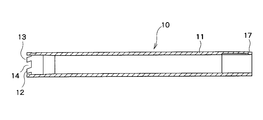
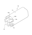
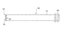
- FIG. 1 is a side view showing a bobbin for a thermal transfer sheet or an image receiving sheet according to the present invention.
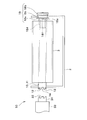
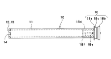
- FIG. 2 is a plan view showing a combination of a sheet and a bobbin.
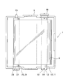
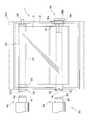
- FIG. 3 is a plan view showing a combination of a sheet and a bobbin mounted in the thermal transfer printer.
- 4A is a side view showing the supply bobbin, and FIG. 4B is an enlarged view thereof.
- FIG. 5 is a side sectional view showing a supply bobbin.
- FIG. 6 is a perspective view showing a supply bobbin.
- FIG. 7 is a side view showing a supply bobbin having a flange portion.
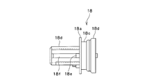
- FIG. 8 is a side view showing the flange portion.
- FIG. 9 is a side view of a bobbin body showing a modification of the present invention.
- FIG. 10 is a side view of a bobbin body showing a modification of the present invention.
- FIG. 1 to 8 are diagrams showing an embodiment of the present invention.
- a ribbon cartridge (bobbin and sheet combination) 1 in which a thermal transfer sheet or image receiving sheet bobbin 10 according to the present invention is incorporated will be described with reference to FIG.
- the ribbon cartridge 1 includes a supply-side bobbin 10, a winding-side bobbin 20, and a storage case 2 that stores the supply-side bobbin 10 and the winding-side bobbin 20, and the supply-side bobbin 10 and the winding-side bobbin 20
- An ink ribbon (thermal transfer sheet) 3 having a support layer and an ink layer is provided between them.
- the ink ribbon 3 is fixed to the supply side bobbin 10 and the take-up side bobbin 20, respectively.
- the take-up bobbin 20 has a cylindrical bobbin main body 21, a gear flange 22 formed integrally with the bobbin main body 21 at one end of the bobbin main body 21, and a bobbin.
- a support shaft 25 formed integrally with the bobbin main body 21 is provided at the other end of the main body 21.
- “one side end of the bobbin main body 21” refers to the entire one side end of the bobbin main body 21 in the axial direction
- the other side end of the bobbin main body 21 refers to the other side of the bobbin main body 21 in the axial direction. Refers to the entire side edge.
- the gear flange 22 has a plurality of teeth 22 a on the inner peripheral surface, and the teeth 22 a formed on the inner peripheral surface are fitted with the drive unit 40 of the thermal transfer printer 50, and the winding bobbin is taken up by the drive unit 40. 20 is rotationally driven (see FIG. 3).
- the bobbin body 21 of the winding side bobbin 20 is provided with a circumferential protrusion 23 in the vicinity of the gear flange 22, and a portion of the bobbin body 21 between the gear flange 22 and the circumferential protrusion 23. Is fitted into the storage case 2, and the winding-side bobbin 20 is positioned in the storage case 2 along the axial direction.
- the drive unit 40 of the thermal transfer printer 50 has a drive shaft 41, and a drive gear 42 that fits the teeth 22 a of the gear flange 22 is formed at the end of the drive shaft 41.
- the supply-side bobbin 10 includes a cylindrical bobbin body 11, and a gear 12 having a plurality of teeth 13 and a tooth groove 14 formed between the teeth 13 is formed at one end of the bobbin body 11.
- the gear 12 is adapted to be fitted to a braking gear 32 of a braking shaft 31 provided in the braking unit 30 of the thermal transfer printer 50.
- one side end of the bobbin main body 11 refers to the entire one side end of the bobbin main body 11 in the axial direction
- the other end of the bobbin main body 11 refers to the axial direction of the bobbin main body 11. The other end of the other side.
- a plurality of fitting grooves 17 are formed at the other end of the bobbin main body 11, and when the flange portion 18 is attached to the other side of the bobbin main body 11, the fitting protrusion 18 e of the flange portion 18 is formed on the bobbin main body 11. It fits in the fitting groove 17.
- the supply-side bobbin 10 includes the bobbin body 11, and the gear 12 is provided at one end of the bobbin body 11.
- the gear 12 has a plurality of teeth 13 and a tooth groove 14 formed between the teeth 13, and each tooth 13 has four corners 15 a, 15 b, 15 c, 15 d as a whole when viewed from the side surface of the bobbin body 11. It has a parallelogram shape having four sides 13a, 13b, 13c, and 13d (see FIGS. 4A and 4B).
- “when viewed from the side” has a meaning when viewed from the side perpendicular to the axial direction of the bobbin main body 11.
- each tooth 13 has a parallelogram shape having four corners 15a, 15b, 15c, 15d and sides 13a, 13b, 13c, 13d formed between the corners 15a, 15b, 15c, 15d.
- a parallelogram shape having four corners 15a, 15b, 15c, 15d and sides 13a, 13b, 13c, 13d formed between the corners 15a, 15b, 15c, 15d.
- the side 13d is a virtual side that does not constitute the outer surface of the gear 12.
- the sides 13 a, 13 b, 13 c and 13 d extend perpendicular to the axis of the bobbin main body 11. Further, the sides 13 b and 13 c are inclined with respect to the axis of the bobbin main body 11.
- the braking gear 32 fitted to the gear 12 has a concave portion having a shape corresponding to the parallelogram shape of each tooth 13 so that each tooth 13 of the gear 12 can be reliably received. Further, since the sides 13a and 13d extend perpendicular to the axis of the bobbin main body 11, the teeth 13 of the gear 12 can be more reliably received.
- each tooth 13 includes chamfered curved surfaces.
- the sides 13a, 13b, and 13c of each tooth 13 are curved so as to protrude outward.
- a groove 13e directed inward is formed in the side 13c. In this case, by forming the groove 13e, the gear 12 and each tooth 13 can be fitted more firmly.
- each tooth 13 has chamfered curved surfaces, and the sides 13a, 13b, 13c are curved so as to protrude outward, so that the tooth 13 Will have a curved surface as a whole.
- the operator who operates the bobbins 10 and 20 is not damaged by the supply-side bobbin 10.
- each tooth 13 of the gear 12 has a parallelogram shape
- the brake gear 32 into which the gear 12 is fitted has a recess having a shape corresponding to the parallelogram shape of each tooth 13.
- the recess of the gear 32 can be firmly fitted.
- the parallelogram shape of each tooth 13 has sides 13b and 13c that are inclined with respect to the axial direction of the bobbin main body 11, the rotation in the R direction around the axis of the bobbin main body 11 from the braking gear 32 to the gear 12 is performed. Power can be transmitted reliably.
- the bobbin main body 11 configured in this way is arranged on the same axis with respect to the braking shaft 31 of the thermal transfer printer 50, and the braking shaft 31 reliably brakes the bobbin main body 11 side via the braking gear 32 and the gear 12. can do.
- the flange portion 18 attached to the bobbin main body 11 will be described.
- the flange portion 18 is attached to the other side of the bobbin body 11, and includes a first flange 18a, a second flange 18b, a first flange 18a, and a second flange 18b. And a fitting portion 18 c that is formed between them and fitted into the storage case 2.
- the first flange 18a is connected to a cylindrical portion 18d mounted in the bobbin main body 11.
- cylindrical portion 18d of the flange portion 18 is provided with a fitting protrusion 18e that is fitted to the fitting groove 17 of the bobbin main body 11 adjacent to the first flange 18a.
- cylindrical portion 18d of the flange portion 18 is provided with an axial rib 18f having a protrusion height lower than that of the fitting protrusion 18e and extending in the axial direction.
- the axial rib 18f of the flange portion 18 is formed on the inner surface of the bobbin body 11. It fits into an axial groove (not shown) formed in.
- the flange portion 18 configured in this manner is configured separately from the bobbin main body 11 and attached to the bobbin main body 11. In this way, the supply-side bobbin 10 is configured.
- a supply-side bobbin 10 around which the ink ribbon 3 is wound and a winding-side bobbin 20 are prepared.
- the ink ribbon 3 is pressed and wound around the supply-side bobbin 10 using a touch roller.
- the supply-side bobbin 10 and the winding-side bobbin 20 are mounted in the storage case 2, and the storage case 2, the supply-side bobbin 10 and the winding-side bobbin 20 around which the ink ribbon 3 is wound in this way.
- a ribbon cartridge (bobbin and sheet combination) 1 having the above is obtained.
- the ribbon cartridge 1 is mounted on the mounting portion 50A of the thermal transfer printer 50.
- the winding-side bobbin 20 of the ribbon cartridge 1 is aligned on the same axis as the drive shaft 41 of the braking unit 40 of the thermal transfer printer 50, and the supply-side bobbin 10 is the same as the braking shaft 31 of the braking shaft 30 of the thermal transfer printer 50. Line up on the axis.
- the drive unit 40 is pressed toward the winding side bobbin 20, and the drive gear 40 of the driving unit 40 is fitted to the gear flange 22 (the teeth 22 a formed on the inner peripheral surface) of the winding side bobbin 20. .
- the braking unit 30 is pressed toward the supply side bobbin 10, and the braking gear 32 formed on the braking shaft 31 of the braking unit 30 is engaged with the gear 12 of the supply side bobbin 10.
- each tooth 13 of the gear 12 has a parallelogram shape when viewed from the side, and the braking gear 32 of the braking unit 30 and the supply side bobbin 10 are simply pressed against the supply side bobbin 10.
- One of the gears 12 is slightly rotated, and the braking gear 32 of the braking unit 30 and the gear 12 of the supply-side bobbin 10 can be easily and easily engaged.
- the winding bobbin 20 is driven by the driving unit 40, and the supply-side bobbin 10 is braked by a brake (not shown) built in the braking unit 30.
- a brake (not shown) built in the braking unit 30.
- the ink ribbon 3 wound around the supply side bobbin 10 is supplied.
- the ink ribbon 3 extending between the supply side bobbin 10 and the take-up side bobbin 20 is heated by a thermal head (not shown), and the ink of the ink ribbon 3 is transferred to an image receiving sheet (not shown).
- the thermal transfer operation is performed.
- the gear 12 including the plurality of teeth 13 is formed at one end of the bobbin main body 11 of the supply-side bobbin 10.
- the drive gear 32 of the drive unit 30 can be directly fitted, and the drive force in the rotational direction from the drive shaft 31 of the drive unit 30 can be directly transmitted to the bobbin main body 11.
- each tooth 13 of the gear 12 has a parallelogram shape as a whole when viewed from the side, so that the braking of the gear 12 and the braking unit 30 can be easily and simply performed by simply pressing the braking unit 30 against the gear 12.
- the gear 32 can be fitted.
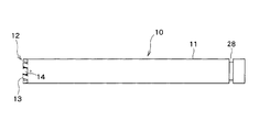
- FIGS. 1 to 8 the example in which the flange portion 18 is attached to the other side end of the bobbin main body 11 of the supply side bobbin 10 is shown.
- a circumferential groove 28 for positioning the supply-side bobbin 10 by being fitted to the storage case 2 may be provided at the other end of 11.
- the gear 12 having a plurality of teeth 13 and a tooth groove 14 formed between the teeth 13. Is formed.
- the supply-side bobbin 10 comprises only the bobbin main body 11 and does not have a flange portion, so the number of components can be further deleted.
- FIGS. 1 to 8 the example in which the flange portion 18 is attached to the other side end of the bobbin main body 11 of the supply side bobbin 10 is shown.
- the present invention is not limited to this, and as shown in FIG. A pair of circumferential projections 29 for positioning the supply-side bobbin 10 by fitting into the storage case 2 may be provided at the other end of the main body 11.
- the gear 12 As shown in FIG. 10, on one side of the bobbin main body 11, as in the embodiment shown in FIGS. 1 to 8, the gear 12 having a plurality of teeth 13 and tooth spaces 14 formed between the teeth 13. Is formed.
- the supply-side bobbin 10 consists only of the bobbin main body 11 and does not have a flange portion, so that the number of components can be further deleted.
- the ink ribbon (thermal transfer sheet) 3 is wound around the supply-side bobbin 10 and the winding-side bobbin 20 has been described.
- an image receiving sheet is placed on the supply-side bobbin 10 and the winding-side bobbin 20.
- the winding and supply side bobbin 10 and the winding side bobbin 20 can also be used as image receiving sheet bobbins.
Landscapes
- Impression-Transfer Materials And Handling Thereof (AREA)
- Electronic Switches (AREA)
- Storage Of Web-Like Or Filamentary Materials (AREA)
Priority Applications (4)
| Application Number | Priority Date | Filing Date | Title |
|---|---|---|---|
| KR1020187015042A KR102134331B1 (ko) | 2015-11-30 | 2016-11-29 | 열 전사 시트 또는 수상 시트용 보빈, 보빈과 시트의 조합체 및 열 전사 프린터 |
| EP16870672.9A EP3357848B1 (en) | 2015-11-30 | 2016-11-29 | Bobbin for thermal transfer sheet or image receiving sheet, combined body of bobbin and sheet, and thermal transfer printer |
| CN201680068328.4A CN108290701B (zh) | 2015-11-30 | 2016-11-29 | 热转印片或显像片用卷轴、卷轴与片的组合体以及热转印打印机 |
| US15/773,252 US10486434B2 (en) | 2015-11-30 | 2016-11-29 | Bobbin for thermal transfer sheet or image-receiving sheet, assembly of bobbin and sheet, and thermal transfer printer |
Applications Claiming Priority (2)
| Application Number | Priority Date | Filing Date | Title |
|---|---|---|---|
| JP2015233382A JP6395057B2 (ja) | 2015-11-30 | 2015-11-30 | 熱転写シートまたは受像シート用ボビン、ボビンとシートの組合体および熱転写プリンタ |
| JP2015-233382 | 2015-11-30 |
Publications (1)
| Publication Number | Publication Date |
|---|---|
| WO2017094735A1 true WO2017094735A1 (ja) | 2017-06-08 |
Family
ID=58796934
Family Applications (1)
| Application Number | Title | Priority Date | Filing Date |
|---|---|---|---|
| PCT/JP2016/085450 Ceased WO2017094735A1 (ja) | 2015-11-30 | 2016-11-29 | 熱転写シートまたは受像シート用ボビン、ボビンとシートの組合体および熱転写プリンタ |
Country Status (7)
| Country | Link |
|---|---|
| US (1) | US10486434B2 (enExample) |
| EP (1) | EP3357848B1 (enExample) |
| JP (1) | JP6395057B2 (enExample) |
| KR (1) | KR102134331B1 (enExample) |
| CN (1) | CN108290701B (enExample) |
| MY (1) | MY176097A (enExample) |
| WO (1) | WO2017094735A1 (enExample) |
Families Citing this family (1)
| Publication number | Priority date | Publication date | Assignee | Title |
|---|---|---|---|---|
| KR102671765B1 (ko) * | 2021-11-30 | 2024-06-04 | 디에스글로벌(주) | 잉크리본 코어 및 그를 위한 열전사 인쇄장치용 엔진 |
Citations (5)
| Publication number | Priority date | Publication date | Assignee | Title |
|---|---|---|---|---|
| JPS63170058A (ja) * | 1987-01-09 | 1988-07-13 | Hitachi Ltd | インク紙カセツト |
| JPH10129067A (ja) * | 1996-10-31 | 1998-05-19 | Minolta Co Ltd | インクフィルムカセットおよびインクフィルムカセットに用いられるリール |
| JP2001122523A (ja) | 1999-10-22 | 2001-05-08 | Dainippon Printing Co Ltd | 巻枠及びフランジ |
| JP2001150775A (ja) | 1999-11-25 | 2001-06-05 | Dainippon Printing Co Ltd | ボビン |
| JP2006315273A (ja) * | 2005-05-12 | 2006-11-24 | Sony Corp | インクリボンカセット |
Family Cites Families (17)
| Publication number | Priority date | Publication date | Assignee | Title |
|---|---|---|---|---|
| JPS61277540A (ja) | 1985-06-03 | 1986-12-08 | Matsushita Electric Ind Co Ltd | 定トルク機構 |
| US4892425A (en) | 1987-01-09 | 1990-01-09 | Hitachi, Ltd. | Thermal transfer recording apparatus and ink sheet cassette therefor |
| JPH07100555B2 (ja) * | 1989-06-28 | 1995-11-01 | 株式会社テック | ウェブ保持装置 |
| DE3909979A1 (de) | 1989-03-25 | 1990-09-27 | Zimmermann Jos Gmbh & Co Kg | Wickeltraeger zur aufnahme von garnen sowie verfahren zu seiner anwendung |
| KR930002400Y1 (ko) * | 1990-12-17 | 1993-05-10 | 주식회사 에스케이씨 | 필름(Film) 권취용 보빈 아답터(ADADTER) |
| JPH0920043A (ja) | 1995-07-06 | 1997-01-21 | Graphtec Corp | 記録用ロール取付構造 |
| US6457885B1 (en) * | 1996-10-31 | 2002-10-01 | Minolta Co., Ltd. | Thermal transfer recording apparatus, ink film cassette and ink film reel |
| JPH10252767A (ja) * | 1997-03-11 | 1998-09-22 | Fuji Xerox Co Ltd | 駆動力伝達装置 |
| JP2002046945A (ja) * | 2000-08-01 | 2002-02-12 | Dainippon Printing Co Ltd | 巻 枠 |
| JP2002132091A (ja) * | 2000-10-23 | 2002-05-09 | Seiko Epson Corp | 画像形成装置 |
| JP2004291392A (ja) | 2003-03-27 | 2004-10-21 | Pilot Corporation | リボンカセット |
| KR200409328Y1 (ko) * | 2005-11-28 | 2006-02-22 | 송영만 | 보빈 |
| JP4411272B2 (ja) | 2005-12-21 | 2010-02-10 | Necアクセステクニカ株式会社 | フィルムシャフト機構、熱転写記録装置およびフィルムシャフト |
| JP6247011B2 (ja) * | 2013-03-29 | 2017-12-13 | キヤノンファインテックニスカ株式会社 | 印刷装置 |
| CN204280784U (zh) | 2014-10-17 | 2015-04-22 | 汕头市远东轻化装备有限公司 | 一种气胀夹紧夹头 |
| JP6297514B2 (ja) * | 2015-03-19 | 2018-03-20 | セイコーエプソン株式会社 | テープカートリッジ |
| JP6361678B2 (ja) * | 2016-03-17 | 2018-07-25 | 住友電気工業株式会社 | ボビン |
-
2015
- 2015-11-30 JP JP2015233382A patent/JP6395057B2/ja active Active
-
2016
- 2016-11-29 MY MYPI2018702020A patent/MY176097A/en unknown
- 2016-11-29 KR KR1020187015042A patent/KR102134331B1/ko active Active
- 2016-11-29 US US15/773,252 patent/US10486434B2/en active Active
- 2016-11-29 EP EP16870672.9A patent/EP3357848B1/en active Active
- 2016-11-29 CN CN201680068328.4A patent/CN108290701B/zh active Active
- 2016-11-29 WO PCT/JP2016/085450 patent/WO2017094735A1/ja not_active Ceased
Patent Citations (5)
| Publication number | Priority date | Publication date | Assignee | Title |
|---|---|---|---|---|
| JPS63170058A (ja) * | 1987-01-09 | 1988-07-13 | Hitachi Ltd | インク紙カセツト |
| JPH10129067A (ja) * | 1996-10-31 | 1998-05-19 | Minolta Co Ltd | インクフィルムカセットおよびインクフィルムカセットに用いられるリール |
| JP2001122523A (ja) | 1999-10-22 | 2001-05-08 | Dainippon Printing Co Ltd | 巻枠及びフランジ |
| JP2001150775A (ja) | 1999-11-25 | 2001-06-05 | Dainippon Printing Co Ltd | ボビン |
| JP2006315273A (ja) * | 2005-05-12 | 2006-11-24 | Sony Corp | インクリボンカセット |
Also Published As
| Publication number | Publication date |
|---|---|
| KR20180089411A (ko) | 2018-08-08 |
| EP3357848A4 (en) | 2019-06-19 |
| JP2017100821A (ja) | 2017-06-08 |
| CN108290701A (zh) | 2018-07-17 |
| EP3357848A1 (en) | 2018-08-08 |
| CN108290701B (zh) | 2019-12-31 |
| US10486434B2 (en) | 2019-11-26 |
| US20180326742A1 (en) | 2018-11-15 |
| EP3357848B1 (en) | 2020-11-18 |
| MY176097A (en) | 2020-07-24 |
| JP6395057B2 (ja) | 2018-09-26 |
| KR102134331B1 (ko) | 2020-07-16 |
Similar Documents
| Publication | Publication Date | Title |
|---|---|---|
| CN104507695B (zh) | 墨带支座和印刷装置 | |
| WO2017086340A1 (ja) | 熱転写シートまたは受像シート用ボビン、ボビンとシートの組合体および熱転写プリンタ | |
| JP6265377B2 (ja) | 熱転写シートまたは受像シート用ボビン、ボビンとシートの組合体および熱転写プリンタ | |
| JP6395057B2 (ja) | 熱転写シートまたは受像シート用ボビン、ボビンとシートの組合体および熱転写プリンタ | |
| CN100484768C (zh) | 墨带盒 | |
| JP7069706B2 (ja) | リボン巻取り機構およびテープ印刷装置 | |
| WO2015151545A1 (ja) | プリンタ | |
| JP6103993B2 (ja) | ペーパーフランジユニット | |
| JP4830045B2 (ja) | 帯状媒体のたるみ防止機構および画像記録装置 | |
| JP4595092B2 (ja) | インクリボンスプール | |
| JP4136083B2 (ja) | 塗布膜転写具 | |
| KR102671765B1 (ko) | 잉크리본 코어 및 그를 위한 열전사 인쇄장치용 엔진 | |
| JP2012061739A (ja) | サーマルプリンタ | |
| JP2017100821A5 (enExample) | ||
| JP4652290B2 (ja) | 帯状媒体のたるみ防止機構および画像記録装置 | |
| JP2005007686A (ja) | インクリボンセット | |
| JP3109602U (ja) | 支持筒体及び交換用インクリボン | |
| JP6468489B2 (ja) | リボンカートリッジおよびリボンカートリッジとプリンタの組合体 | |
| JP2004243727A (ja) | リボンカセット | |
| JP2007144725A (ja) | プラテンローラ保持構造 | |
| WO2021065467A1 (ja) | 印刷用カセット | |
| JP2023029393A (ja) | カセット | |
| JP6500478B2 (ja) | ボビンとプリンタの組合体およびボビン | |
| JP2016060165A (ja) | ボビンとプリンタの組合体およびボビン |
Legal Events
| Date | Code | Title | Description |
|---|---|---|---|
| 121 | Ep: the epo has been informed by wipo that ep was designated in this application |
Ref document number: 16870672 Country of ref document: EP Kind code of ref document: A1 |
|
| WWE | Wipo information: entry into national phase |
Ref document number: 15773252 Country of ref document: US |
|
| WWE | Wipo information: entry into national phase |
Ref document number: 2016870672 Country of ref document: EP |
|
| ENP | Entry into the national phase |
Ref document number: 20187015042 Country of ref document: KR Kind code of ref document: A |
|
| NENP | Non-entry into the national phase |
Ref country code: DE |