WO2017043374A1 - オーステナイト系ステンレス鋼板の溶接方法 - Google Patents
オーステナイト系ステンレス鋼板の溶接方法 Download PDFInfo
- Publication number
- WO2017043374A1 WO2017043374A1 PCT/JP2016/075349 JP2016075349W WO2017043374A1 WO 2017043374 A1 WO2017043374 A1 WO 2017043374A1 JP 2016075349 W JP2016075349 W JP 2016075349W WO 2017043374 A1 WO2017043374 A1 WO 2017043374A1
- Authority
- WO
- WIPO (PCT)
- Prior art keywords
- mass
- welding
- less
- austenitic stainless
- stainless steel
- Prior art date
- Legal status (The legal status is an assumption and is not a legal conclusion. Google has not performed a legal analysis and makes no representation as to the accuracy of the status listed.)
- Ceased
Links
Images


Classifications
-
- B—PERFORMING OPERATIONS; TRANSPORTING
- B23—MACHINE TOOLS; METAL-WORKING NOT OTHERWISE PROVIDED FOR
- B23K—SOLDERING OR UNSOLDERING; WELDING; CLADDING OR PLATING BY SOLDERING OR WELDING; CUTTING BY APPLYING HEAT LOCALLY, e.g. FLAME CUTTING; WORKING BY LASER BEAM
- B23K31/00—Processes relevant to this subclass, specially adapted for particular articles or purposes, but not covered by any single one of main groups B23K1/00 - B23K28/00
- B23K31/02—Processes relevant to this subclass, specially adapted for particular articles or purposes, but not covered by any single one of main groups B23K1/00 - B23K28/00 relating to soldering or welding
-
- B—PERFORMING OPERATIONS; TRANSPORTING
- B23—MACHINE TOOLS; METAL-WORKING NOT OTHERWISE PROVIDED FOR
- B23K—SOLDERING OR UNSOLDERING; WELDING; CLADDING OR PLATING BY SOLDERING OR WELDING; CUTTING BY APPLYING HEAT LOCALLY, e.g. FLAME CUTTING; WORKING BY LASER BEAM
- B23K9/00—Arc welding or cutting
- B23K9/02—Seam welding; Backing means; Inserts
-
- B—PERFORMING OPERATIONS; TRANSPORTING
- B23—MACHINE TOOLS; METAL-WORKING NOT OTHERWISE PROVIDED FOR
- B23K—SOLDERING OR UNSOLDERING; WELDING; CLADDING OR PLATING BY SOLDERING OR WELDING; CUTTING BY APPLYING HEAT LOCALLY, e.g. FLAME CUTTING; WORKING BY LASER BEAM
- B23K9/00—Arc welding or cutting
- B23K9/02—Seam welding; Backing means; Inserts
- B23K9/025—Seam welding; Backing means; Inserts for rectilinear seams
-
- B—PERFORMING OPERATIONS; TRANSPORTING
- B23—MACHINE TOOLS; METAL-WORKING NOT OTHERWISE PROVIDED FOR
- B23K—SOLDERING OR UNSOLDERING; WELDING; CLADDING OR PLATING BY SOLDERING OR WELDING; CUTTING BY APPLYING HEAT LOCALLY, e.g. FLAME CUTTING; WORKING BY LASER BEAM
- B23K9/00—Arc welding or cutting
- B23K9/02—Seam welding; Backing means; Inserts
- B23K9/028—Seam welding; Backing means; Inserts for curved planar seams
- B23K9/0282—Seam welding; Backing means; Inserts for curved planar seams for welding tube sections
- B23K9/0284—Seam welding; Backing means; Inserts for curved planar seams for welding tube sections with an electrode working inside the tube
-
- B—PERFORMING OPERATIONS; TRANSPORTING
- B23—MACHINE TOOLS; METAL-WORKING NOT OTHERWISE PROVIDED FOR
- B23K—SOLDERING OR UNSOLDERING; WELDING; CLADDING OR PLATING BY SOLDERING OR WELDING; CUTTING BY APPLYING HEAT LOCALLY, e.g. FLAME CUTTING; WORKING BY LASER BEAM
- B23K9/00—Arc welding or cutting
- B23K9/16—Arc welding or cutting making use of shielding gas
- B23K9/167—Arc welding or cutting making use of shielding gas and of a non-consumable electrode
-
- B—PERFORMING OPERATIONS; TRANSPORTING
- B23—MACHINE TOOLS; METAL-WORKING NOT OTHERWISE PROVIDED FOR
- B23K—SOLDERING OR UNSOLDERING; WELDING; CLADDING OR PLATING BY SOLDERING OR WELDING; CUTTING BY APPLYING HEAT LOCALLY, e.g. FLAME CUTTING; WORKING BY LASER BEAM
- B23K9/00—Arc welding or cutting
- B23K9/16—Arc welding or cutting making use of shielding gas
- B23K9/173—Arc welding or cutting making use of shielding gas and of a consumable electrode
-
- B—PERFORMING OPERATIONS; TRANSPORTING
- B23—MACHINE TOOLS; METAL-WORKING NOT OTHERWISE PROVIDED FOR
- B23K—SOLDERING OR UNSOLDERING; WELDING; CLADDING OR PLATING BY SOLDERING OR WELDING; CUTTING BY APPLYING HEAT LOCALLY, e.g. FLAME CUTTING; WORKING BY LASER BEAM
- B23K9/00—Arc welding or cutting
- B23K9/23—Arc welding or cutting taking account of the properties of the materials to be welded
-
- C—CHEMISTRY; METALLURGY
- C21—METALLURGY OF IRON
- C21D—MODIFYING THE PHYSICAL STRUCTURE OF FERROUS METALS; GENERAL DEVICES FOR HEAT TREATMENT OF FERROUS OR NON-FERROUS METALS OR ALLOYS; MAKING METAL MALLEABLE, e.g. BY DECARBURISATION OR TEMPERING
- C21D6/00—Heat treatment of ferrous alloys
- C21D6/004—Heat treatment of ferrous alloys containing Cr and Ni
-
- C—CHEMISTRY; METALLURGY
- C21—METALLURGY OF IRON
- C21D—MODIFYING THE PHYSICAL STRUCTURE OF FERROUS METALS; GENERAL DEVICES FOR HEAT TREATMENT OF FERROUS OR NON-FERROUS METALS OR ALLOYS; MAKING METAL MALLEABLE, e.g. BY DECARBURISATION OR TEMPERING
- C21D9/00—Heat treatment, e.g. annealing, hardening, quenching or tempering, adapted for particular articles; Furnaces therefor
- C21D9/50—Heat treatment, e.g. annealing, hardening, quenching or tempering, adapted for particular articles; Furnaces therefor for welded joints
- C21D9/505—Cooling thereof
-
- C—CHEMISTRY; METALLURGY
- C22—METALLURGY; FERROUS OR NON-FERROUS ALLOYS; TREATMENT OF ALLOYS OR NON-FERROUS METALS
- C22C—ALLOYS
- C22C38/00—Ferrous alloys, e.g. steel alloys
-
- C—CHEMISTRY; METALLURGY
- C22—METALLURGY; FERROUS OR NON-FERROUS ALLOYS; TREATMENT OF ALLOYS OR NON-FERROUS METALS
- C22C—ALLOYS
- C22C38/00—Ferrous alloys, e.g. steel alloys
- C22C38/001—Ferrous alloys, e.g. steel alloys containing N
-
- C—CHEMISTRY; METALLURGY
- C22—METALLURGY; FERROUS OR NON-FERROUS ALLOYS; TREATMENT OF ALLOYS OR NON-FERROUS METALS
- C22C—ALLOYS
- C22C38/00—Ferrous alloys, e.g. steel alloys
- C22C38/002—Ferrous alloys, e.g. steel alloys containing In, Mg, or other elements not provided for in one single group C22C38/001 - C22C38/60
-
- C—CHEMISTRY; METALLURGY
- C22—METALLURGY; FERROUS OR NON-FERROUS ALLOYS; TREATMENT OF ALLOYS OR NON-FERROUS METALS
- C22C—ALLOYS
- C22C38/00—Ferrous alloys, e.g. steel alloys
- C22C38/04—Ferrous alloys, e.g. steel alloys containing manganese
-
- C—CHEMISTRY; METALLURGY
- C22—METALLURGY; FERROUS OR NON-FERROUS ALLOYS; TREATMENT OF ALLOYS OR NON-FERROUS METALS
- C22C—ALLOYS
- C22C38/00—Ferrous alloys, e.g. steel alloys
- C22C38/06—Ferrous alloys, e.g. steel alloys containing aluminium
-
- C—CHEMISTRY; METALLURGY
- C22—METALLURGY; FERROUS OR NON-FERROUS ALLOYS; TREATMENT OF ALLOYS OR NON-FERROUS METALS
- C22C—ALLOYS
- C22C38/00—Ferrous alloys, e.g. steel alloys
- C22C38/18—Ferrous alloys, e.g. steel alloys containing chromium
- C22C38/34—Ferrous alloys, e.g. steel alloys containing chromium with more than 1.5% by weight of silicon
-
- C—CHEMISTRY; METALLURGY
- C22—METALLURGY; FERROUS OR NON-FERROUS ALLOYS; TREATMENT OF ALLOYS OR NON-FERROUS METALS
- C22C—ALLOYS
- C22C38/00—Ferrous alloys, e.g. steel alloys
- C22C38/18—Ferrous alloys, e.g. steel alloys containing chromium
- C22C38/40—Ferrous alloys, e.g. steel alloys containing chromium with nickel
- C22C38/42—Ferrous alloys, e.g. steel alloys containing chromium with nickel with copper
-
- C—CHEMISTRY; METALLURGY
- C22—METALLURGY; FERROUS OR NON-FERROUS ALLOYS; TREATMENT OF ALLOYS OR NON-FERROUS METALS
- C22C—ALLOYS
- C22C38/00—Ferrous alloys, e.g. steel alloys
- C22C38/18—Ferrous alloys, e.g. steel alloys containing chromium
- C22C38/40—Ferrous alloys, e.g. steel alloys containing chromium with nickel
- C22C38/44—Ferrous alloys, e.g. steel alloys containing chromium with nickel with molybdenum or tungsten
-
- C—CHEMISTRY; METALLURGY
- C22—METALLURGY; FERROUS OR NON-FERROUS ALLOYS; TREATMENT OF ALLOYS OR NON-FERROUS METALS
- C22C—ALLOYS
- C22C38/00—Ferrous alloys, e.g. steel alloys
- C22C38/18—Ferrous alloys, e.g. steel alloys containing chromium
- C22C38/40—Ferrous alloys, e.g. steel alloys containing chromium with nickel
- C22C38/46—Ferrous alloys, e.g. steel alloys containing chromium with nickel with vanadium
-
- C—CHEMISTRY; METALLURGY
- C22—METALLURGY; FERROUS OR NON-FERROUS ALLOYS; TREATMENT OF ALLOYS OR NON-FERROUS METALS
- C22C—ALLOYS
- C22C38/00—Ferrous alloys, e.g. steel alloys
- C22C38/18—Ferrous alloys, e.g. steel alloys containing chromium
- C22C38/40—Ferrous alloys, e.g. steel alloys containing chromium with nickel
- C22C38/48—Ferrous alloys, e.g. steel alloys containing chromium with nickel with niobium or tantalum
-
- C—CHEMISTRY; METALLURGY
- C22—METALLURGY; FERROUS OR NON-FERROUS ALLOYS; TREATMENT OF ALLOYS OR NON-FERROUS METALS
- C22C—ALLOYS
- C22C38/00—Ferrous alloys, e.g. steel alloys
- C22C38/18—Ferrous alloys, e.g. steel alloys containing chromium
- C22C38/40—Ferrous alloys, e.g. steel alloys containing chromium with nickel
- C22C38/50—Ferrous alloys, e.g. steel alloys containing chromium with nickel with titanium or zirconium
-
- C—CHEMISTRY; METALLURGY
- C22—METALLURGY; FERROUS OR NON-FERROUS ALLOYS; TREATMENT OF ALLOYS OR NON-FERROUS METALS
- C22C—ALLOYS
- C22C38/00—Ferrous alloys, e.g. steel alloys
- C22C38/18—Ferrous alloys, e.g. steel alloys containing chromium
- C22C38/40—Ferrous alloys, e.g. steel alloys containing chromium with nickel
- C22C38/54—Ferrous alloys, e.g. steel alloys containing chromium with nickel with boron
-
- B—PERFORMING OPERATIONS; TRANSPORTING
- B23—MACHINE TOOLS; METAL-WORKING NOT OTHERWISE PROVIDED FOR
- B23K—SOLDERING OR UNSOLDERING; WELDING; CLADDING OR PLATING BY SOLDERING OR WELDING; CUTTING BY APPLYING HEAT LOCALLY, e.g. FLAME CUTTING; WORKING BY LASER BEAM
- B23K2101/00—Articles made by soldering, welding or cutting
- B23K2101/04—Tubular or hollow articles
- B23K2101/06—Tubes
-
- B—PERFORMING OPERATIONS; TRANSPORTING
- B23—MACHINE TOOLS; METAL-WORKING NOT OTHERWISE PROVIDED FOR
- B23K—SOLDERING OR UNSOLDERING; WELDING; CLADDING OR PLATING BY SOLDERING OR WELDING; CUTTING BY APPLYING HEAT LOCALLY, e.g. FLAME CUTTING; WORKING BY LASER BEAM
- B23K2101/00—Articles made by soldering, welding or cutting
- B23K2101/18—Sheet panels
-
- B—PERFORMING OPERATIONS; TRANSPORTING
- B23—MACHINE TOOLS; METAL-WORKING NOT OTHERWISE PROVIDED FOR
- B23K—SOLDERING OR UNSOLDERING; WELDING; CLADDING OR PLATING BY SOLDERING OR WELDING; CUTTING BY APPLYING HEAT LOCALLY, e.g. FLAME CUTTING; WORKING BY LASER BEAM
- B23K2103/00—Materials to be soldered, welded or cut
- B23K2103/02—Iron or ferrous alloys
- B23K2103/04—Steel or steel alloys
- B23K2103/05—Stainless steel
-
- B—PERFORMING OPERATIONS; TRANSPORTING
- B23—MACHINE TOOLS; METAL-WORKING NOT OTHERWISE PROVIDED FOR
- B23K—SOLDERING OR UNSOLDERING; WELDING; CLADDING OR PLATING BY SOLDERING OR WELDING; CUTTING BY APPLYING HEAT LOCALLY, e.g. FLAME CUTTING; WORKING BY LASER BEAM
- B23K35/00—Rods, electrodes, materials, or media, for use in soldering, welding, or cutting
- B23K35/001—Interlayers, transition pieces for metallurgical bonding of workpieces
- B23K35/004—Interlayers, transition pieces for metallurgical bonding of workpieces at least one of the workpieces being of a metal of the iron group
-
- B—PERFORMING OPERATIONS; TRANSPORTING
- B23—MACHINE TOOLS; METAL-WORKING NOT OTHERWISE PROVIDED FOR
- B23K—SOLDERING OR UNSOLDERING; WELDING; CLADDING OR PLATING BY SOLDERING OR WELDING; CUTTING BY APPLYING HEAT LOCALLY, e.g. FLAME CUTTING; WORKING BY LASER BEAM
- B23K35/00—Rods, electrodes, materials, or media, for use in soldering, welding, or cutting
- B23K35/22—Rods, electrodes, materials, or media, for use in soldering, welding, or cutting characterised by the composition or nature of the material
- B23K35/24—Selection of soldering or welding materials proper
- B23K35/30—Selection of soldering or welding materials proper with the principal constituent melting at less than 1550°C
- B23K35/3053—Fe as the principal constituent
- B23K35/308—Fe as the principal constituent with Cr as next major constituent
- B23K35/3086—Fe as the principal constituent with Cr as next major constituent containing Ni or Mn
-
- C—CHEMISTRY; METALLURGY
- C21—METALLURGY OF IRON
- C21D—MODIFYING THE PHYSICAL STRUCTURE OF FERROUS METALS; GENERAL DEVICES FOR HEAT TREATMENT OF FERROUS OR NON-FERROUS METALS OR ALLOYS; MAKING METAL MALLEABLE, e.g. BY DECARBURISATION OR TEMPERING
- C21D2211/00—Microstructure comprising significant phases
- C21D2211/001—Austenite
-
- C—CHEMISTRY; METALLURGY
- C22—METALLURGY; FERROUS OR NON-FERROUS ALLOYS; TREATMENT OF ALLOYS OR NON-FERROUS METALS
- C22C—ALLOYS
- C22C38/00—Ferrous alloys, e.g. steel alloys
- C22C38/18—Ferrous alloys, e.g. steel alloys containing chromium
- C22C38/40—Ferrous alloys, e.g. steel alloys containing chromium with nickel
- C22C38/58—Ferrous alloys, e.g. steel alloys containing chromium with nickel with more than 1.5% by weight of manganese
Definitions
- the present invention relates to a welding method for an austenitic stainless steel sheet for welding austenitic stainless steel sheets in a stacked manner.
- a dual structure exhaust manifold is installed that has an inner pipe and an outer pipe, and a gap is provided between the inner pipe and the outer pipe.
- ferritic stainless steel with a low coefficient of thermal expansion is usually used for the single structure exhaust manifold, but austenitic stainless steel, which has better workability than ferritic stainless steel, is used for the inner pipe of the dual structure exhaust manifold. Used.
- the inner and outer pipes of the dual structure exhaust manifold are often manufactured by fillet welding by arc welding such as MIG welding with the press-molded pipe parts overlapped.
- the present invention has been made in view of these points, and an object of the present invention is to provide a method for welding an austenitic stainless steel sheet in which welding defects are less likely to occur.
- the welding method for the austenitic stainless steel sheet according to claim 1 is as follows: C: 0.08 mass% or less, Si: 1.5 mass% or more and 4.0 mass% or less, Mn: 2.0 mass% or less, P : 0.04 mass% or less, S: 0.01 mass% or less, Cr: 16.0 mass% or more and 22.0 mass% or less, Ni: 10.0 mass% or more and 14.0 mass% or less, and N : 0.08% by mass or less, and at least one of Nb and Ti in total containing 1.0% by mass or less, with the balance being composed of Fe and inevitable impurities.
- An austenitic stainless steel plate of 0 mm or less is overlapped and the overlap portion is welded by arc welding, and the weld back surface portion, which is the highest temperature at the time of welding on the weld back surface, starts from 1200 ° C. at a cooling rate of 110 ° C./second or more. Cool to 900 ° C It is intended to.
- the welding method for an austenitic stainless steel sheet according to claim 2 is the welding method for an austenitic stainless steel sheet according to claim 1, wherein the austenitic stainless steel sheet includes at least one of Al, Zr and V in total 1 0.0 mass% or less.
- the welding method for an austenitic stainless steel sheet according to claim 3 is the welding method for an austenitic stainless steel sheet according to claim 1 or 2, wherein the austenitic stainless steel sheet is a total of 4.0 of at least one of Mo and Cu. It is contained in mass% or less.
- the method for welding an austenitic stainless steel sheet according to claim 4 is the welding method for an austenitic stainless steel sheet according to any one of claims 1 to 3, wherein the austenitic stainless steel sheet contains 0.01% by mass or less of B. To do.
- the welding method for an austenitic stainless steel sheet according to claim 5 is the welding method for an austenitic stainless steel sheet according to any one of claims 1 to 4, wherein the overlap length of the welded joint portion when welding the lap portion is long.
- the thickness is 2.5 mm or more.
- the welding back surface portion which is the highest temperature portion during welding, is cooled from 1200 ° C. to 900 ° C. at a cooling rate of 110 ° C./second or more. Can be prevented and welding defects can be prevented.
- the dual structure exhaust manifold includes an outer pipe and an inner pipe disposed inside the outer pipe via a gap. These outer pipe and inner pipe are each MIG welded using a welding rod such as a welding wire in the weld joint 1 shown in FIG. 1, and a hollow heat insulating layer is arranged between the outer pipe and the inner pipe. It is fixed in the state.
- the welded joint portion 1 includes a pipe base material part 2, a pipe base material part 3, a welded part 4 in which these pipe base material parts 2 and 3 are welded, and a pipe base.
- the structure includes a bond portion 5 that is a boundary between the material portions 2 and 3 and the weld portion 4.
- the broken line of FIG. 1 shows the set state of the pipe
- the inner pipe is thinner than the outer pipe, and it is very difficult to control the amount of heat input during welding, so it is important to make it difficult for weld defects such as high temperature cracking and ductile degradation cracking to occur.
- an austenitic stainless steel plate having a thickness of 0.6 mm or more and 1.0 mm or less, which is superior in workability to ferritic stainless steel, is used for the inner tube.
- the austenitic stainless steel of the inner pipe is specifically designed as follows.
- the base tube component (austenitic stainless steel) of the inner pipe is 0.08 mass% or less C (carbon), 1.5 mass% or more and 4.0 mass% or less Si (silicon), 2.0 mass% or less.
- Mn manganese
- P phosphorus
- S sulfur
- Cr chromium
- It contains 0 mass% or more and 14.0 mass% or less of Ni (nickel) and 0.08 mass% or less of N (nitrogen), and at least one of Nb (niobium) and Ti (titanium) in total 1 0.0 mass% or less, and the balance is composed of Fe (iron) and inevitable impurities.
- the austenitic stainless steel may contain a total of 1.0% by mass or less of at least one of Al (aluminum), Zr (zirconium), and V (vanadium) as necessary.
- the austenitic stainless steel may be configured to contain a total of 4.0% by mass or less of at least one of Mo (molybdenum) and Cu (copper) as necessary.
- the austenitic stainless steel may contain 0.01% by mass or less of B (boron) as necessary.
- the C is effective in improving the high temperature strength of austenitic stainless steel, but if it is contained in excess of 0.08 mass%, Cr carbide may be formed during use and the toughness may deteriorate. There is a possibility that the amount of solid solution Cr effective in improving the high temperature oxidation resistance may be reduced. Therefore, the C content is set to 0.08% by mass or less (excluding no addition).
- Si is very effective in improving high-temperature oxidation characteristics.
- a Si concentrated film is formed inside the Cr oxide in the temperature range of 850 to 900 ° C. , Contributes to the improvement of scale peel resistance.
- the content of Si is set to 1.5% by mass or more and 4.0% by mass or less, preferably 3.0% by mass or more and 4.0% by mass or less.
- Mn is an austenite phase stabilizing element and mainly has an effect of adjusting the ⁇ phase balance.
- the content of Mn is set to 2.0% by mass or less (excluding no addition).
- the content of P is set to 0.04% by mass or less.
- S may cause the hot workability of the austenitic stainless steel to be lowered if it is contained in an amount exceeding 0.01% by mass as in the case of P, it is preferable to reduce the content as much as possible. Therefore, the S content is 0.01% by mass or less.
- Cr is an element that suppresses scale formation at high temperatures and is effective in improving high-temperature oxidation characteristics. To exhibit such effects, it is necessary to contain 16.0% by mass or more. On the other hand, when Cr is excessively contained exceeding 22.0 mass%, ⁇ embrittlement may be induced. Therefore, the Cr content is 16.0 mass% or more and 22.0 mass% or less.
- Ni is an austenite phase stabilizing element, and is contained mainly for adjusting the ⁇ phase balance, but in order to achieve such an action, it is necessary to contain 10.0% by mass or more. On the other hand, if Ni is excessively contained, the cost is increased, so the upper limit of the Ni content is 14.0% by mass. Therefore, the Ni content is 10.0% by mass or more and 14.0% by mass or less.
- N is an element that improves the high-temperature strength by solid solution strengthening, but if it is excessively contained in excess of 0.08 mass%, the toughness may be reduced due to the formation of Cr nitride. Therefore, the content of N is set to 0.08% by mass or less (excluding no addition).
- Nb and Ti are elements that combine with C and N to improve the high temperature strength, but if contained excessively, there is a possibility of lowering the melting point. Therefore, when Nb and Ti are contained for the purpose of improving the high-temperature strength, at least one of Nb and Ti is contained in a total amount of 1.0% by mass or less.
- Al is a strong ferrite-forming element and is effective in stabilizing the ⁇ phase.
- Zr and V are elements that combine with C and N to improve the high temperature strength.
- Al, Zr and V are contained excessively, there is a possibility that the melting point is lowered. Therefore, when Al, Zr and V are contained for the purpose of improving the high temperature strength, it is preferable to contain at least one of Al, Zr and V in a total amount of 1.0% by mass or less.
- Mo is a ferrite-forming element and is effective in improving the high-temperature strength. However, if excessively contained, ⁇ embrittlement may be caused and the toughness may be reduced.
- Cu is an austenite-forming element and is useful for improving the high-temperature strength. However, if excessively contained, Cu may cause a decrease in high-temperature oxidation resistance. Therefore, when Mo and Cu are contained for the purpose of improving high temperature strength, it is preferable to contain at least one of Mo and Cu in a total amount of 4.0% by mass or less.
- the content of B when B is contained for the purpose of improving heat resistance is preferably 0.01% by mass or less.
- MIG welding is performed with the inner pipes partially overlapped.
- the welding conditions in MIG welding, the type of the welding core wire, the flow rate of the shielding gas, and the like can be set and selected as appropriate.
- inert gas such as argon and nitrogen
- oxygen concentration in an inert gas into 5.0 volume% or less from a viewpoint of prevention of the entrainment of the oxide in a welding part.
- the welding back surface portion 7 which is the highest temperature on the welding back surface 6 after welding is cooled from 1200 ° C. to 900 ° C. at a cooling rate of 110 ° C./second or more.
- a method of increasing the cooling rate after welding and increasing the cooling rate to 110 ° C./second or more for example, a method of reducing the heat input itself in welding within the allowable range in the properties of the product, or promoting heat transfer Therefore, a method of attaching a contact plate such as Cu to the welding back surface 6, a method of adjusting the flow rate of the back shield gas, a method of spraying the shielding gas directly on the welding back surface 6 and the like can be appropriately performed.
- the overlapping portion 8 where the steel plates overlap each other that is most difficult to transfer heat during welding. Therefore, in order to increase the volume of the overlapping portion 8 and promote heat conduction (heat transfer), a configuration in which the length of the overlapping margin W of the overlapping portion 8 is 2.5 mm or more is preferable. It is more preferable that it is 4.0 mm or more.
- the cooling rate at the time of cooling the welded back surface portion 7 which is the portion of the welded back surface 6 where the temperature is highest during welding from 1200 ° C. to 900 ° C. is 110 ° C./second.
- heat generated during welding can be transferred to another part at an early stage on the welding back surface 6 where welding defects are likely to occur. Therefore, the influence by the heat
- the length of the overlap margin W when welding the overlap portion 8 when welding the overlap portion 8 to 2.5 mm or more, the volume of the overlap portion 8 can be increased to promote heat conduction (heat transfer), and the cooling rate can be increased. Therefore, the occurrence of welding defects can be effectively prevented. Furthermore, if the length of the overlap margin W is 4.0 mm or more, the occurrence of welding defects can be more effectively prevented.
- the MIG welding method is used as the arc welding.
- a TIG welding method, a MAG welding method, a covered arc welding method, and the like are also applicable.
- the overlap portion 8 is fillet welded.
- the vicinity of the central portion of the overlap portion 8 may be welded as in the modification shown in FIG.
- the above-described welding method for austenitic stainless steel plates can be applied both when welding austenitic stainless steel plates and when welding austenitic stainless steel plates with other materials.
- An austenitic stainless steel having the components shown in Table 1 was melted to form a cold-rolled annealed plate having a thickness of 0.8 mm.
- a plate-shaped specimen of 100 ⁇ 200 mm was cut out from each cold-rolled annealed plate.
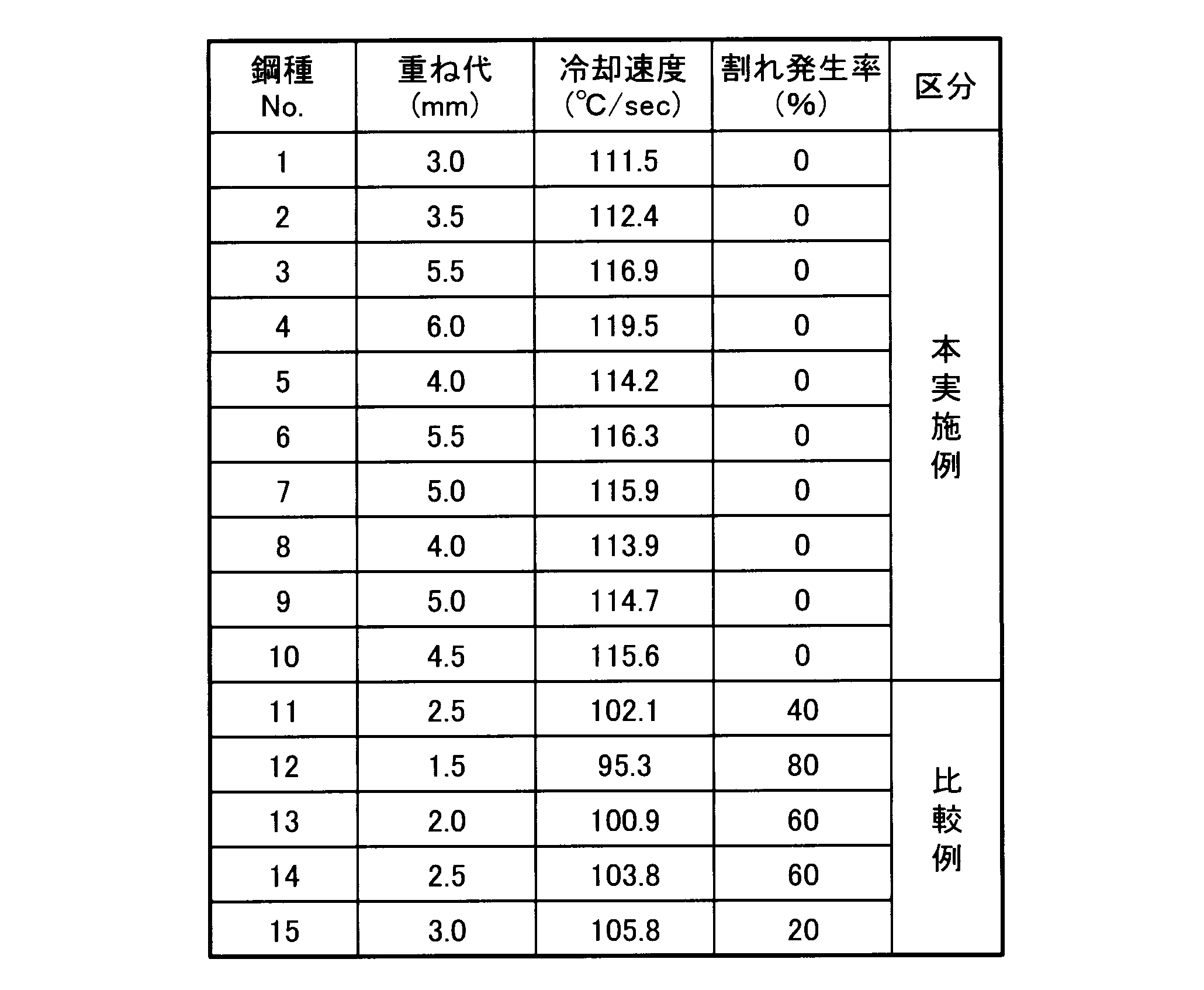
- Table 2 shows the overlap allowance in each steel type, the cooling rate when the welded back surface portion is cooled from 1200 ° C. to 900 ° C., and the crack generation rate, and the relationship between the cooling rate and the crack generation rate is shown in FIG. In FIG. 3, ⁇ indicates a case where no crack occurred, and ⁇ indicates a case where a crack occurred.
- the steel grade No. which is the present example having a cooling rate of 110 ° C./second or more when cooling the welding back surface portion from 1200 ° C. to 900 ° C. 1 to steel type no. In all of the samples, no cracks occurred on the weld back surface, and the weldability was excellent.
- steel type No. which is a comparative example in which the cooling rate when cooling the welding back surface portion from 1200 ° C. to 900 ° C. is less than 110 ° C./second. 11 to steel type No. In all 15, weld cracks occurred, and the weldability was insufficient.
- the present invention can be used when an austenitic stainless steel plate is stacked and welded, for example, when a double structure exhaust manifold or the like is manufactured.
Landscapes
- Chemical & Material Sciences (AREA)
- Engineering & Computer Science (AREA)
- Mechanical Engineering (AREA)
- Materials Engineering (AREA)
- Metallurgy (AREA)
- Organic Chemistry (AREA)
- Physics & Mathematics (AREA)
- Plasma & Fusion (AREA)
- Crystallography & Structural Chemistry (AREA)
- Thermal Sciences (AREA)
- Arc Welding In General (AREA)
- Butt Welding And Welding Of Specific Article (AREA)
- Heat Treatment Of Articles (AREA)
- Heat Treatment Of Sheet Steel (AREA)
Abstract
Description

6 溶接裏面
7 溶着裏面部
8 重ね部
W 重ね代
Claims (5)
- C:0.08質量%以下、Si:1.5質量%以上4.0質量%以下、Mn:2.0質量%以下、P:0.04質量%以下、S:0.01質量%以下、Cr:16.0質量%以上22.0質量%以下、Ni:10.0質量%以上14.0質量%以下、および、N:0.08質量%以下を含有するとともに、NbおよびTiの少なくとも1種を合計1.0質量%以下含有し、残部がFeおよび不可避的不純物にて構成された板厚0.6mm以上1.0mm以下のオーステナイト系ステンレス鋼板を重ねてアーク溶接にて重ね部を溶接し、
溶接裏面において溶接時に温度が最高となる部位である溶着裏面部を、110℃/秒以上の冷却速度で1200℃から900℃まで冷却する
ことを特徴とするオーステナイト系ステンレス鋼板の溶接方法。 - オーステナイト系ステンレス鋼板は、Al、ZrおよびVのうちの少なくとも1種を合計1.0質量%以下含有する
ことを特徴とする請求項1記載のオーステナイト系ステンレス鋼板の溶接方法。 - オーステナイト系ステンレス鋼板は、MoおよびCuの少なくとも1種を合計4.0質量%以下含有する
ことを特徴とする請求項1または2記載のオーステナイト系ステンレス鋼板の溶接方法。 - オーステナイト系ステンレス鋼板は、Bを0.01質量%以下含有する
ことを特徴とする請求項1ないし3いずれか一記載のオーステナイト系ステンレス鋼板の溶接方法。 - 重ね部を溶接する際の溶接継手部の重ね代の長さを2.5mm以上とする
ことを特徴とする請求項1ないし4いずれか一記載のオーステナイト系ステンレス鋼板の溶接方法。
Priority Applications (5)
| Application Number | Priority Date | Filing Date | Title |
|---|---|---|---|
| CA2995056A CA2995056C (en) | 2015-09-08 | 2016-08-30 | Method for welding austenitic stainless steel sheets |
| US15/757,718 US20190039165A1 (en) | 2015-09-08 | 2016-08-30 | Method for welding austenitic stainless steel sheets |
| MX2018002886A MX2018002886A (es) | 2015-09-08 | 2016-08-30 | Metodo para soldar laminas de acero inoxidable austeniticas. |
| CN201680051321.1A CN108025385A (zh) | 2015-09-08 | 2016-08-30 | 奥氏体系不锈钢板的焊接方法 |
| KR1020187003871A KR101989288B1 (ko) | 2015-09-08 | 2016-08-30 | 오스테나이트계 스테인리스 강판의 용접 방법 |
Applications Claiming Priority (2)
| Application Number | Priority Date | Filing Date | Title |
|---|---|---|---|
| JP2015-176734 | 2015-09-08 | ||
| JP2015176734A JP6499557B2 (ja) | 2015-09-08 | 2015-09-08 | オーステナイト系ステンレス鋼板の溶接方法 |
Publications (1)
| Publication Number | Publication Date |
|---|---|
| WO2017043374A1 true WO2017043374A1 (ja) | 2017-03-16 |
Family
ID=58239566
Family Applications (1)
| Application Number | Title | Priority Date | Filing Date |
|---|---|---|---|
| PCT/JP2016/075349 Ceased WO2017043374A1 (ja) | 2015-09-08 | 2016-08-30 | オーステナイト系ステンレス鋼板の溶接方法 |
Country Status (8)
| Country | Link |
|---|---|
| US (1) | US20190039165A1 (ja) |
| JP (1) | JP6499557B2 (ja) |
| KR (1) | KR101989288B1 (ja) |
| CN (1) | CN108025385A (ja) |
| CA (1) | CA2995056C (ja) |
| MX (1) | MX2018002886A (ja) |
| TW (1) | TWI690606B (ja) |
| WO (1) | WO2017043374A1 (ja) |
Cited By (3)
| Publication number | Priority date | Publication date | Assignee | Title |
|---|---|---|---|---|
| JP2019044243A (ja) * | 2017-09-05 | 2019-03-22 | 日新製鋼株式会社 | 安定オーステナイト系ステンレス溶接部材 |
| JP2019044242A (ja) * | 2017-09-05 | 2019-03-22 | 日新製鋼株式会社 | オーステナイト系ステンレス溶接部材 |
| WO2022102183A1 (ja) * | 2020-11-13 | 2022-05-19 | 日本製鉄株式会社 | 二重管および溶接継手 |
Families Citing this family (4)
| Publication number | Priority date | Publication date | Assignee | Title |
|---|---|---|---|---|
| JP2018176217A (ja) * | 2017-04-12 | 2018-11-15 | 株式会社Uacj | 溶接継手 |
| EP3957425A4 (en) * | 2019-04-19 | 2022-06-22 | Panasonic Intellectual Property Management Co., Ltd. | ASSEMBLY STRUCTURE |
| CN111715982A (zh) * | 2020-05-21 | 2020-09-29 | 太原科技大学 | 一种新型高合金奥氏体耐热不锈钢的焊接方法 |
| WO2024171851A1 (ja) | 2023-02-14 | 2024-08-22 | 日鉄ステンレス株式会社 | 溶接継手 |
Citations (3)
| Publication number | Priority date | Publication date | Assignee | Title |
|---|---|---|---|---|
| JPH11104882A (ja) * | 1997-10-06 | 1999-04-20 | Osaka Gas Co Ltd | Fe−Ni系低熱膨張率合金の溶接方法 |
| JP2004131843A (ja) * | 2002-09-18 | 2004-04-30 | Jfe Steel Kk | 構造物構築部材およびその製造方法 |
| JP2006159262A (ja) * | 2004-12-08 | 2006-06-22 | Sumitomo Metal Ind Ltd | 溶接継手および溶接材料 |
Family Cites Families (19)
| Publication number | Priority date | Publication date | Assignee | Title |
|---|---|---|---|---|
| JPS5483646A (en) * | 1977-12-16 | 1979-07-03 | Hitachi Ltd | Welding method for austenitic stainless steel |
| JPS5545555A (en) * | 1978-09-25 | 1980-03-31 | Hitachi Zosen Corp | Welding method of austenitic stainless steel |
| JPS58167723A (ja) * | 1982-03-30 | 1983-10-04 | Kubota Ltd | ステンレス鋼材の加工方法 |
| JPH08334018A (ja) | 1995-06-07 | 1996-12-17 | Nissan Motor Co Ltd | エンジンの二重排気管 |
| JPH08334017A (ja) | 1995-06-07 | 1996-12-17 | Nissan Motor Co Ltd | エンジンの二重排気管 |
| JPH1161275A (ja) * | 1997-08-07 | 1999-03-05 | Mitsubishi Heavy Ind Ltd | オーステナイト系ステンレス鋼の溶接部 |
| JPH1193654A (ja) | 1997-09-24 | 1999-04-06 | Nippon Soken Inc | エキゾーストマニホールド |
| JP2003074339A (ja) * | 2001-06-18 | 2003-03-12 | Calsonic Kansei Corp | 二重管エキゾーストマニホールド |
| FR2835456B1 (fr) * | 2002-02-01 | 2004-04-02 | Air Liquide | Procede de soudage d'elements de vehicules automobiles, en particulier de flancs raboutes |
| DK2199420T3 (da) * | 2007-10-04 | 2013-06-10 | Nippon Steel & Sumitomo Metal Corp | Austenitisk rustfrit stål |
| CN101229605A (zh) * | 2008-02-02 | 2008-07-30 | 泰山集团泰安市普瑞特机械制造有限公司 | 奥氏体不锈钢氩弧焊水冷焊接法 |
| CN101733523B (zh) * | 2010-01-12 | 2011-12-07 | 中国石油大学(华东) | 中厚板双相不锈钢焊接工艺 |
| CN102225487A (zh) * | 2011-06-03 | 2011-10-26 | 唐山三友集团兴达化纤有限公司 | 用超低碳奥氏体不锈钢制作喷射泵的焊接方法 |
| CN102357718B (zh) * | 2011-10-14 | 2013-06-05 | 河北首钢燕郊机械有限责任公司 | 一种防止产生焊缝裂纹的不锈钢薄板的焊接方法 |
| CN102732803A (zh) * | 2012-06-26 | 2012-10-17 | 江苏兴海特钢有限公司 | 一种奥氏体不锈钢 |
| KR101707345B1 (ko) * | 2012-09-04 | 2017-02-15 | 신닛테츠스미킨 카부시키카이샤 | 정밀 가공용 스테인리스 강판 및 그 제조 방법 |
| CN102941401B (zh) * | 2012-10-30 | 2015-02-25 | 太原理工大学 | 一种铁素体不锈钢的随焊激冷焊接方法 |
| CN104878316A (zh) * | 2014-02-27 | 2015-09-02 | 南京理工大学 | 一种高强韧高氮奥氏体不锈钢 |
| CN104480409B (zh) * | 2014-12-10 | 2017-05-03 | 无锡鑫常钢管有限责任公司 | 一种06Cr17Ni12Mo2Ti奥氏体不锈钢管及生产工艺 |
-
2015
- 2015-09-08 JP JP2015176734A patent/JP6499557B2/ja active Active
-
2016
- 2016-08-30 CN CN201680051321.1A patent/CN108025385A/zh active Pending
- 2016-08-30 WO PCT/JP2016/075349 patent/WO2017043374A1/ja not_active Ceased
- 2016-08-30 KR KR1020187003871A patent/KR101989288B1/ko active Active
- 2016-08-30 CA CA2995056A patent/CA2995056C/en active Active
- 2016-08-30 MX MX2018002886A patent/MX2018002886A/es unknown
- 2016-08-30 US US15/757,718 patent/US20190039165A1/en not_active Abandoned
- 2016-09-08 TW TW105129113A patent/TWI690606B/zh active
Patent Citations (3)
| Publication number | Priority date | Publication date | Assignee | Title |
|---|---|---|---|---|
| JPH11104882A (ja) * | 1997-10-06 | 1999-04-20 | Osaka Gas Co Ltd | Fe−Ni系低熱膨張率合金の溶接方法 |
| JP2004131843A (ja) * | 2002-09-18 | 2004-04-30 | Jfe Steel Kk | 構造物構築部材およびその製造方法 |
| JP2006159262A (ja) * | 2004-12-08 | 2006-06-22 | Sumitomo Metal Ind Ltd | 溶接継手および溶接材料 |
Cited By (7)
| Publication number | Priority date | Publication date | Assignee | Title |
|---|---|---|---|---|
| JP2019044243A (ja) * | 2017-09-05 | 2019-03-22 | 日新製鋼株式会社 | 安定オーステナイト系ステンレス溶接部材 |
| JP2019044242A (ja) * | 2017-09-05 | 2019-03-22 | 日新製鋼株式会社 | オーステナイト系ステンレス溶接部材 |
| WO2022102183A1 (ja) * | 2020-11-13 | 2022-05-19 | 日本製鉄株式会社 | 二重管および溶接継手 |
| JPWO2022102183A1 (ja) * | 2020-11-13 | 2022-05-19 | ||
| KR20230106174A (ko) * | 2020-11-13 | 2023-07-12 | 닛폰세이테츠 가부시키가이샤 | 이중관 및 용접 이음 |
| JP7602147B2 (ja) | 2020-11-13 | 2024-12-18 | 日本製鉄株式会社 | 二重管および溶接継手 |
| KR102862685B1 (ko) | 2020-11-13 | 2025-09-22 | 닛폰세이테츠 가부시키가이샤 | 이중관 및 용접 이음 |
Also Published As
| Publication number | Publication date |
|---|---|
| KR20180040140A (ko) | 2018-04-19 |
| TW201715057A (zh) | 2017-05-01 |
| JP2017051968A (ja) | 2017-03-16 |
| KR101989288B1 (ko) | 2019-06-13 |
| CN108025385A (zh) | 2018-05-11 |
| JP6499557B2 (ja) | 2019-04-10 |
| US20190039165A1 (en) | 2019-02-07 |
| MX2018002886A (es) | 2018-06-18 |
| CA2995056C (en) | 2019-04-23 |
| CA2995056A1 (en) | 2017-03-16 |
| TWI690606B (zh) | 2020-04-11 |
Similar Documents
| Publication | Publication Date | Title |
|---|---|---|
| JP6499557B2 (ja) | オーステナイト系ステンレス鋼板の溶接方法 | |
| JP5202862B2 (ja) | 耐低温割れ性に優れた溶接金属を有する高強度溶接鋼管およびその製造方法 | |
| JP6566126B2 (ja) | 溶接構造部材 | |
| JP2008030076A (ja) | オーステナイト系ステンレス鋼溶接継手及びオーステナイト系ステンレス鋼溶接材料 | |
| CN111183239A (zh) | 奥氏体系不锈钢焊接金属以及焊接结构物 | |
| JP2016037614A (ja) | フェライト系ステンレス鋼溶接構造体及び固体酸化物型燃料電池の耐熱部材 | |
| KR102658542B1 (ko) | 고Cr 페라이트계 내열강용 피복 아크 용접봉 | |
| JP6566125B2 (ja) | 溶接構造部材 | |
| JP2015199107A (ja) | FeCrAl合金溶接ワイヤーおよびこれを用いた溶接構造体 | |
| WO2013122234A1 (ja) | 溶接管構造高温機器用オーステナイト系ステンレス鋼 | |
| JP6235402B2 (ja) | 強度、靭性および耐sr割れ性に優れた溶接金属 | |
| JP6249839B2 (ja) | 二重構造エキゾーストマニホールド | |
| WO2000036173A1 (en) | Steel for boiler excellent in butt seam weldability and electroseamed steel pipe for boiler using the same | |
| KR20180034646A (ko) | 서브머지드 아크 용접용 와이어 | |
| JP2018144060A (ja) | Tig溶接用溶加材 | |
| CN111194360A (zh) | 奥氏体系不锈钢 | |
| KR20190087846A (ko) | 극저온 Ni 합금강용 Ni기 플럭스 코어드 와이어 | |
| WO1994020258A1 (fr) | Fil electrode de soudage a l'arc au gaz inerte pour acier ferritique refractaire riche en chrome | |
| JP4584002B2 (ja) | フェライト系ステンレス鋼溶接用フラックス入りワイヤ | |
| CN113490571B (zh) | 高Cr铁素体系耐热钢用焊接材料 | |
| JP6249840B2 (ja) | 二重構造エキゾーストマニホールド | |
| JP7707533B2 (ja) | フェライト系ステンレス鋼溶接ワイヤ | |
| JP7436793B2 (ja) | フェライト系耐熱鋼の溶接継手の製造方法 | |
| KR20260050876A (ko) | 용접방법 | |
| TW202417162A (zh) | 肥粒鐵系不鏽鋼焊線及焊接部件 |
Legal Events
| Date | Code | Title | Description |
|---|---|---|---|
| 121 | Ep: the epo has been informed by wipo that ep was designated in this application |
Ref document number: 16844235 Country of ref document: EP Kind code of ref document: A1 |
|
| ENP | Entry into the national phase |
Ref document number: 2995056 Country of ref document: CA |
|
| ENP | Entry into the national phase |
Ref document number: 20187003871 Country of ref document: KR Kind code of ref document: A |
|
| WWE | Wipo information: entry into national phase |
Ref document number: MX/A/2018/002886 Country of ref document: MX |
|
| NENP | Non-entry into the national phase |
Ref country code: DE |
|
| 122 | Ep: pct application non-entry in european phase |
Ref document number: 16844235 Country of ref document: EP Kind code of ref document: A1 |