WO2017033462A1 - ガラス板加工装置 - Google Patents
ガラス板加工装置 Download PDFInfo
- Publication number
- WO2017033462A1 WO2017033462A1 PCT/JP2016/003864 JP2016003864W WO2017033462A1 WO 2017033462 A1 WO2017033462 A1 WO 2017033462A1 JP 2016003864 W JP2016003864 W JP 2016003864W WO 2017033462 A1 WO2017033462 A1 WO 2017033462A1
- Authority
- WO
- WIPO (PCT)
- Prior art keywords
- glass plate
- grinding
- glass
- axis
- scribe
- Prior art date
- Legal status (The legal status is an assumption and is not a legal conclusion. Google has not performed a legal analysis and makes no representation as to the accuracy of the status listed.)
- Ceased
Links
Images

Classifications
-
- C—CHEMISTRY; METALLURGY
- C03—GLASS; MINERAL OR SLAG WOOL
- C03B—MANUFACTURE, SHAPING, OR SUPPLEMENTARY PROCESSES
- C03B33/00—Severing cooled glass
- C03B33/02—Cutting or splitting sheet glass or ribbons; Apparatus or machines therefor
- C03B33/023—Cutting or splitting sheet glass or ribbons; Apparatus or machines therefor the sheet or ribbon being in a horizontal position
- C03B33/033—Apparatus for opening score lines in glass sheets
-
- C—CHEMISTRY; METALLURGY
- C03—GLASS; MINERAL OR SLAG WOOL
- C03B—MANUFACTURE, SHAPING, OR SUPPLEMENTARY PROCESSES
- C03B33/00—Severing cooled glass
- C03B33/02—Cutting or splitting sheet glass or ribbons; Apparatus or machines therefor
- C03B33/023—Cutting or splitting sheet glass or ribbons; Apparatus or machines therefor the sheet or ribbon being in a horizontal position
- C03B33/03—Glass cutting tables; Apparatus for transporting or handling sheet glass during the cutting or breaking operations
-
- B—PERFORMING OPERATIONS; TRANSPORTING
- B24—GRINDING; POLISHING
- B24B—MACHINES, DEVICES, OR PROCESSES FOR GRINDING OR POLISHING; DRESSING OR CONDITIONING OF ABRADING SURFACES; FEEDING OF GRINDING, POLISHING, OR LAPPING AGENTS
- B24B41/00—Component parts such as frames, beds, carriages, headstocks
- B24B41/06—Work supports, e.g. adjustable steadies
- B24B41/068—Table-like supports for panels, sheets or the like
-
- B—PERFORMING OPERATIONS; TRANSPORTING
- B24—GRINDING; POLISHING
- B24B—MACHINES, DEVICES, OR PROCESSES FOR GRINDING OR POLISHING; DRESSING OR CONDITIONING OF ABRADING SURFACES; FEEDING OF GRINDING, POLISHING, OR LAPPING AGENTS
- B24B47/00—Drives or gearings; Equipment therefor
- B24B47/22—Equipment for exact control of the position of the grinding tool or work at the start of the grinding operation
-
- B—PERFORMING OPERATIONS; TRANSPORTING
- B24—GRINDING; POLISHING
- B24B—MACHINES, DEVICES, OR PROCESSES FOR GRINDING OR POLISHING; DRESSING OR CONDITIONING OF ABRADING SURFACES; FEEDING OF GRINDING, POLISHING, OR LAPPING AGENTS
- B24B7/00—Machines or devices designed for grinding plane surfaces on work, including polishing plane glass surfaces; Accessories therefor
- B24B7/20—Machines or devices designed for grinding plane surfaces on work, including polishing plane glass surfaces; Accessories therefor characterised by a special design with respect to properties of the material of non-metallic articles to be ground
- B24B7/22—Machines or devices designed for grinding plane surfaces on work, including polishing plane glass surfaces; Accessories therefor characterised by a special design with respect to properties of the material of non-metallic articles to be ground for grinding inorganic material, e.g. stone, ceramics, porcelain
- B24B7/24—Machines or devices designed for grinding plane surfaces on work, including polishing plane glass surfaces; Accessories therefor characterised by a special design with respect to properties of the material of non-metallic articles to be ground for grinding inorganic material, e.g. stone, ceramics, porcelain for grinding or polishing glass
- B24B7/241—Methods
-
- B—PERFORMING OPERATIONS; TRANSPORTING
- B24—GRINDING; POLISHING
- B24B—MACHINES, DEVICES, OR PROCESSES FOR GRINDING OR POLISHING; DRESSING OR CONDITIONING OF ABRADING SURFACES; FEEDING OF GRINDING, POLISHING, OR LAPPING AGENTS
- B24B7/00—Machines or devices designed for grinding plane surfaces on work, including polishing plane glass surfaces; Accessories therefor
- B24B7/20—Machines or devices designed for grinding plane surfaces on work, including polishing plane glass surfaces; Accessories therefor characterised by a special design with respect to properties of the material of non-metallic articles to be ground
- B24B7/22—Machines or devices designed for grinding plane surfaces on work, including polishing plane glass surfaces; Accessories therefor characterised by a special design with respect to properties of the material of non-metallic articles to be ground for grinding inorganic material, e.g. stone, ceramics, porcelain
- B24B7/24—Machines or devices designed for grinding plane surfaces on work, including polishing plane glass surfaces; Accessories therefor characterised by a special design with respect to properties of the material of non-metallic articles to be ground for grinding inorganic material, e.g. stone, ceramics, porcelain for grinding or polishing glass
- B24B7/242—Machines or devices designed for grinding plane surfaces on work, including polishing plane glass surfaces; Accessories therefor characterised by a special design with respect to properties of the material of non-metallic articles to be ground for grinding inorganic material, e.g. stone, ceramics, porcelain for grinding or polishing glass for plate glass
- B24B7/245—Machines or devices designed for grinding plane surfaces on work, including polishing plane glass surfaces; Accessories therefor characterised by a special design with respect to properties of the material of non-metallic articles to be ground for grinding inorganic material, e.g. stone, ceramics, porcelain for grinding or polishing glass for plate glass discontinuous
-
- B—PERFORMING OPERATIONS; TRANSPORTING
- B24—GRINDING; POLISHING
- B24B—MACHINES, DEVICES, OR PROCESSES FOR GRINDING OR POLISHING; DRESSING OR CONDITIONING OF ABRADING SURFACES; FEEDING OF GRINDING, POLISHING, OR LAPPING AGENTS
- B24B9/00—Machines or devices designed for grinding edges or bevels on work or for removing burrs; Accessories therefor
- B24B9/02—Machines or devices designed for grinding edges or bevels on work or for removing burrs; Accessories therefor characterised by a special design with respect to properties of materials specific to articles to be ground
- B24B9/06—Machines or devices designed for grinding edges or bevels on work or for removing burrs; Accessories therefor characterised by a special design with respect to properties of materials specific to articles to be ground of non-metallic inorganic material, e.g. stone, ceramics, porcelain
- B24B9/08—Machines or devices designed for grinding edges or bevels on work or for removing burrs; Accessories therefor characterised by a special design with respect to properties of materials specific to articles to be ground of non-metallic inorganic material, e.g. stone, ceramics, porcelain of glass
- B24B9/10—Machines or devices designed for grinding edges or bevels on work or for removing burrs; Accessories therefor characterised by a special design with respect to properties of materials specific to articles to be ground of non-metallic inorganic material, e.g. stone, ceramics, porcelain of glass of plate glass
-
- C—CHEMISTRY; METALLURGY
- C03—GLASS; MINERAL OR SLAG WOOL
- C03B—MANUFACTURE, SHAPING, OR SUPPLEMENTARY PROCESSES
- C03B33/00—Severing cooled glass
- C03B33/02—Cutting or splitting sheet glass or ribbons; Apparatus or machines therefor
- C03B33/023—Cutting or splitting sheet glass or ribbons; Apparatus or machines therefor the sheet or ribbon being in a horizontal position
- C03B33/027—Scoring tool holders; Driving mechanisms therefor
-
- C—CHEMISTRY; METALLURGY
- C03—GLASS; MINERAL OR SLAG WOOL
- C03B—MANUFACTURE, SHAPING, OR SUPPLEMENTARY PROCESSES
- C03B33/00—Severing cooled glass
- C03B33/02—Cutting or splitting sheet glass or ribbons; Apparatus or machines therefor
- C03B33/023—Cutting or splitting sheet glass or ribbons; Apparatus or machines therefor the sheet or ribbon being in a horizontal position
- C03B33/037—Controlling or regulating
-
- B—PERFORMING OPERATIONS; TRANSPORTING
- B65—CONVEYING; PACKING; STORING; HANDLING THIN OR FILAMENTARY MATERIAL
- B65G—TRANSPORT OR STORAGE DEVICES, e.g. CONVEYORS FOR LOADING OR TIPPING, SHOP CONVEYOR SYSTEMS OR PNEUMATIC TUBE CONVEYORS
- B65G2249/00—Aspects relating to conveying systems for the manufacture of fragile sheets
- B65G2249/04—Arrangements of vacuum systems or suction cups
-
- Y—GENERAL TAGGING OF NEW TECHNOLOGICAL DEVELOPMENTS; GENERAL TAGGING OF CROSS-SECTIONAL TECHNOLOGIES SPANNING OVER SEVERAL SECTIONS OF THE IPC; TECHNICAL SUBJECTS COVERED BY FORMER USPC CROSS-REFERENCE ART COLLECTIONS [XRACs] AND DIGESTS
- Y02—TECHNOLOGIES OR APPLICATIONS FOR MITIGATION OR ADAPTATION AGAINST CLIMATE CHANGE
- Y02P—CLIMATE CHANGE MITIGATION TECHNOLOGIES IN THE PRODUCTION OR PROCESSING OF GOODS
- Y02P40/00—Technologies relating to the processing of minerals
- Y02P40/50—Glass production, e.g. reusing waste heat during processing or shaping
- Y02P40/57—Improving the yield, e-g- reduction of reject rates
Definitions
- the present invention is a glass plate processing apparatus that performs cutting (cutting, that is, scribing), folding and peripheral grinding on a glass plate to produce a glass plate for an automobile window and a glass plate for other uses. About.
- the present invention also relates to a glass plate processing apparatus that simultaneously processes at least two glass plates at a cutting (scribing) position, a folding position, and a peripheral grinding position.
- Patent Document 1 two glass plates are simultaneously transferred at the scribe position, the split position, and the peripheral grinding position while the glass plates are transferred to the scribing position, the split position, and the peripheral grinding position at a time.
- a glass plate processing apparatus for processing the target is described.
- the glass plate processing apparatus described in Patent Document 1 includes a main cutting line forming unit having two main cutting lines forming devices and a glass plate peripheral grinding unit having two peripheral cutting devices.
- the scribe heads of the two main slicing line forming devices and the scribe work table supported by the glass plate are simultaneously paralleled by a common X-axis moving means and a common Y-axis moving means. Then, the X-axis movement and the Y-axis movement are performed as a unit, and the same XY coordinate system is controlled and moved to perform scribing on the two corresponding glass plates, respectively.
- the grinding head and the grinding work table are simultaneously moved in the X-axis and Y-axis as a unit, and controlled to move in the same XY coordinate system to perform peripheral grinding on the two corresponding glass plates.
- the two glass plates on which the scribe lines are formed in the main slicing line forming part are the grinding work of the folding part and the peripheral grinding part from the main slicing line forming part by the glass plate conveying device. Is conveyed replaced on Buru, and a glass plate is peripheral grinding at a position on the grinding work table, it is formed to the final finished size.
- the finished size and shape of the two glass plates are distorted due to the shift of the respective carry-in positions of the two glass plates to the peripheral grinding part, and a defective glass plate is manufactured. Is done.
- the glass plate peripheral grinding unit has two peripheral grinding devices corresponding to each of the two loaded glass plates.
- the grinding heads of the respective peripheral grinding devices are integrated as X by a common X-axis moving means.
- the work table to which the axis is moved and the glass plate is adsorbed and fixed is moved as a unit by the common Y axis moving means, that is, the two peripheral grinding devices are integrated. Since the grinding head and work table are controlled and moved in the same XY coordinate system, the positional deviation (error) of the two glass plates cannot be accommodated, and the final finished dimensions and shape are distorted. Resulting in poor grinding quality.
- An object of the present invention is to provide a glass plate processing apparatus that processes two sheets at a time without generating a glass plate having poor grinding quality.
- the glass plate processing apparatus of the present invention comprises a scribe line forming device for forming scribe lines on two glass plates, a glass plate folding device for splitting two glass plates, and the peripheral edges of the two glass plates.
- the control movement of the XY coordinate system is performed independently of each other in the simultaneous grinding of the periphery of the two glass plates in the glass plate peripheral grinding apparatus.
- the glass plate processing apparatus of the present invention includes two scribing positions for forming scribe lines on two glass plates, a folding position for splitting two glass plates, and two controlled and moved in an XY coordinate system.
- the glass plate peripheral grinding device is equipped with a grinding position for grinding the peripheral edge of the corresponding glass plate, and a glass plate transporting device for transferring and transferring two glass plates at each of these positions.
- the control movement of the peripheral grinding apparatus in the XY coordinate system is performed independently of each other.
- the X axis moving means of the grinding head of one glass plate peripheral grinding device and the Y axis moving means of the grinding work table are made independent of each other and numerically controlled (NC) operation independently of each other.
- the glass plate peripheral grinding devices corresponding to the respective glass plates are numerically controlled and moved independently of each other.
- the grinding head and glass plate can be controlled and moved with respect to each glass plate in accordance with the position of each glass plate, and the two glass plates can be ground with precise finished dimensions, shape and quality. Can do.
- two glass plates having different sizes can be ground simultaneously, and can be ground into respective finished dimensions and shapes.
- the numerical control corresponding to the position of the glass plate conveyed to each glass plate peripheral grinding device and corrected can be performed on each glass plate peripheral grinding device.
- glass plates having different dimensions can be ground.
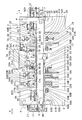
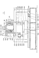
- FIG. 1 is an explanatory front view of a specific example of the glass plate processing apparatus of the present invention.
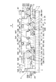
- FIG. 2 is an explanatory plan view of a specific example shown in FIG.
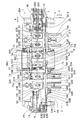
- FIG. 3 is an explanatory rear view of the specific example shown in FIG.
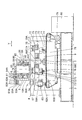
- FIG. 4 is a partially cutaway plan view of one specific example shown in FIG. 5 is a cross-sectional view taken along line VV shown in FIG. 6 is a cross-sectional view taken along line VI-VI in FIG.
- a glass plate processing apparatus 1 includes a base 3 installed on a floor surface F and a pair of gates standing on the base 3 apart from each other in a direction X that is the X-axis direction.
- a frame column 4 having a shape, a straight frame 6 that bridges the frame column 4 in the direction X, an entry position 7, a scribe position 8, and a folding line arranged in series on the base 3 in the direction X.
- the glass plate 2 which is the two raw glass sheets to be supplied, is positioned and placed in series in the conveying direction A parallel to the direction X with an interval, and the entry table 12 comprising a belt conveyor device.
- the scribing position 8 is moved in the direction Y, which is the Y-axis direction orthogonal to the X-axis direction, and the two glass plates 2 conveyed from the entry position 7 are connected in series in the direction X.
- a scribe line forming apparatus 5 having a scribe work table 13 to be supported and two scribe heads 14A and 14B that move in the direction X as a unit is provided.
- a belt that supports the glass plate 2 formed with two scribe lines carried in from the plane in series in the direction X (horizontal)
- a pair of glass plate splitting devices 15A and 15B for cutting and splitting the two glass plates 2 placed on the belt conveyor device 16 and grinding position. 10 includes two glass plate peripheral grinding devices 19A and 19B, and the take-out position 11 includes a take-out belt conveyor device 49.
- the scribe work table 13 receives the two glass plates 2 from the entrance table 12 on the upper surface, and has a table main body 22 for planarly supporting the two glass plates 2 in series in the direction X and spaced from each other.
- a table support base 23 for fixing and supporting a table main body 22 on which two glass plates 2 are placed, and the scribe line forming device 5 moves in the Y axis with the table support base 23 placed thereon;
- the Y-axis moving means 24 is supported by two guide rails 25 arranged side by side along the direction Y on the upper surface of the base 3, and is held by the two guide rails 25 so as to be movable in the direction Y and supported by the table.
- a slide block 26 having a base 23 fixed on the upper surface, a feed screw 27 screwed into a nut attached to the table support base 23 and provided between the two guide rails 25, and one end of the feed screw 27 And the table support base 23 is moved in the direction Y by rotating the feed screw 27 by NC operation, and the table main body 22 is moved in the direction Y, that is, the Y-axis control is performed.
- a motor 28 is provided to rotate the feed screw 27 by NC operation.
- Two scribe heads 14A that are provided on the front surface 69 of the gantry 6 via a common X-axis moving means 36 and move in the direction X corresponding to the table body 22 that moves in the Y-axis, that is, move in the X-axis.
- 14B is provided corresponding to the respective positions of the two glass plates 2 placed on the table body 22.
- the X-axis moving means 36 includes two guide rails 37 arranged side by side on the gantry 6 within the range of the X-axis movement corresponding to the scribe work table 13, and a slide block held by these guide rails 37 so as to be movable in the direction X.
- the scribe heads 14A and 14B are moved in the direction X. That is, an X-axis control motor 40 that moves the X-axis is provided.
- the scribe head 14A is attached to the X-axis moving table 38 via a bearing device 41A.
- the bearing device 41A includes a rotating shaft 42A held by a bearing (not shown), and the rotating shaft 42A is ,
- the plane of the XY coordinate system, that is, the axis center orthogonal to the upper surface of the glass plate 2, and the scribe head main body 44A is attached to the lower end of the rotating shaft 42A via a bracket,
- An angle control motor 45A is connected to the upper end portion via a spur gear.
- the scribe head 14B is attached to the X-axis moving table 38 via a bearing device 41B, and the bearing device 41B includes a rotating shaft 42B held by a bearing (not shown).
- Each of the rotation shafts 42B has an axis that is orthogonal to the plane of the XY coordinate system, that is, the upper surface of the glass plate 2, and a lower end portion of the rotation shaft 42B is scribed via a bracket.
- a head main body 44B is attached, and an angle control motor 45B is connected to an upper end portion thereof via a spur gear.
- the scribing head main body 44A is attached to a cutter head 47A having a cutter wheel 46A at the lower end and an upper part of the cutter head 47A.
- the air cylinder moves the cutter wheel 46A up and down and applies cutting pressure to the cutter wheel 46A during scribing. 48A.
- the scribing head main body 44B like the scribing head main body 44A, is attached to a cutter head 47B having a cutter wheel 46B at the lower end and an upper part of the cutter head 47B. And an air cylinder device 48B that applies a cutting pressure to 46B.
- the cutter wheel 46A is arranged on the axis of the rotating shaft 42A and is controlled to rotate at an angle around an axis perpendicular to the glass plate 2 by the angle control motor 45A via the rotating shaft 42A.
- the cutter wheel 46B is disposed on the axis of the rotating shaft 42B and is rotated about an axis perpendicular to the glass plate 2 via the rotating shaft 42B by the angle control motor 45B. The rotation of the angle is controlled by, so that the blade edge is directed in the scribe direction.
- the pair of glass plate breaking devices 15 ⁇ / b> A is conveyed above the belt conveyor device 16, and the pair of glass plate breaking devices 15 ⁇ / b> B is conveyed above the belt conveyor device 16. It is each arranged with respect to the glass plate 2 on the downstream side in the direction A.
- Each of the pair of glass plate splitting devices 15A and the pair of glass plate splitting devices 15B holds the end-cutting cutter device 70, the press device 71, the end-cutting cutter device 70, and the press device 71.
- the moving means 72 moves these along the upper surface of the glass plate 2, and the moving means 72 holds the end-cutting cutter device 70 and the press device 71 and moves them NC in the Y direction.
- a Y-direction moving device 73 and an X-direction moving device 74 that holds the Y-direction moving device 73 and moves it in the X-axis direction are provided.
- the gantry 6 and the base 3 is attached to a standing body 75 from 3 via a bracket 76.
- the belt conveyor device 16 supports an endless conveyor belt 77 that is wound around four rollers so that it can run freely, and a conveyor belt 77 that is positioned above from the inside to a plane and supports the four pulleys.
- a support plate and frame 78 that is rotatably supported, and a drive device 79 that rotates the conveyor belt 77 and includes an electric motor supported by the base 3 are provided.
- the driving device 79 is supported by the table 3 and rotates one of the four rollers connected to the output rotation shaft of the electric motor via a pulley, a belt, and the like by the operation of the electric motor.
- the conveyor belt 77 is driven by rotation. When the conveyor belt 77 runs, the conveyor belt 77 is broken by the glass plate breaking devices 15A and 15B and remains on the conveyor belt 77. And it is adapted to convey the the end switching cullet of the glass plate 2 to the cullet accommodating container 80.
- the glass plate peripheral grinding device 19A supports the glass plate 2 by suction and moves in the Y direction in the Y direction.
- the glass plate peripheral grinding device 19B includes a single grinding work table 17B that supports the glass plate 2 by suction and is moved in the Y direction in the Y direction, and a Y axis that moves the grinding work table 17B in the Y axis.
- a moving means 31B, a single grinding head 18B moved in the X direction in the direction X, and an X axis moving means 50B for moving the grinding head 18B in the X axis are provided.
- the grinding work table 17A and the grinding work table 17B do not share the Y-axis movement means, and are moved in the Y-axis independently by the Y-axis movement means 31A and 31B.
- the grinding head 18A and the grinding head 18B The X-axis moving means 50A and 50B move the X-axis independently of each other without sharing the axis moving means, and the distance in the direction X between the glass plate peripheral grinding device 19A and the glass plate peripheral grinding device 19B. That is, the distance in the direction X between the grinding work table 17A and the grinding work table 17B is the same as the distance in the direction X of the two glass plates 2 in series conveyed by the glass plate conveying device 20.
- the grinding work table 17A includes a plurality of suction cups 29A that adsorb the glass plate 2 on the upper surface, and a table base 30A that detachably stands the plurality of suction cups 29A. And the table base 30B on which the plurality of suction cups 29B are detachably mounted, and the grinding work table 17A moves in the Y axis in the table base 30A.
- the grinding work table 17B is attached to the Y-axis moving means 31B in the table base 30B, and the Y-axis moving means 31A and the Y-axis moving means 31B are attached to the upper surface of the base 3.
- the grinding work table 17A and the grinding work table 17B are arranged side by side with the above-mentioned interval in the X direction. So as to move the Y-axis independently of one another, adapted to be numerically controlled independently of each other.
- the Y-axis moving means 31A includes two guide rails 32A arranged side by side along the Y-axis direction on the upper surface of the base 3, and a slide block 33A held movably in the direction Y on each of the guide rails 32A. And a feed screw 34A screwed into a nut fixed to the table base 30A and provided between the guide rails 32A, and a Y-axis control motor 35A connected to one end of the feed screw 34A.
- the work table 17A is configured to move the Y axis by driving a Y axis control motor 35A.
- the Y-axis moving means 31B includes two guide rails 32B arranged in parallel along the Y-axis direction on the upper surface of the base 3, and a slide block 33B that is movably held in the direction Y on each of the guide rails 32B.
- a feed screw 34B screwed into a nut fixed to the table base 30B and provided between the guide rails 32B, and a Y-axis control motor 35B connected to one end of the feed screw 34B.
- the work table 17B is configured to move the Y axis by driving a Y axis control motor 35B.
- the grinding head 18A corresponds to the grinding work table 17A.
- the axis is moved, and the grinding head 18B performs X-axis movement corresponding to the grinding work table 17B.
- the grinding head 18A is provided on the gantry 6 via the X-axis moving means 50A, and the grinding head 18B is provided on the gantry 6 via the X-axis moving means 50B.
- the X-axis moving means 50A to which the grinding head 18A is attached has two guide rails 51A arranged side by side on the gantry 6 in the X-axis movement range corresponding to the grinding work table 17A, and is movable in the direction X to the guide rail 51A.
- the X-axis moving table 52A to which the slide block held by the X-axis moving table 52A is fixed the feed screw 53A that is screwed to the nut fixed to the X-axis moving table 52A and provided between the guide rails 51A; 53A and an X-axis control motor 54A connected to one end of the X-axis control motor 54A.
- the X-axis moving table 52A and the grinding head 18A are driven by the X-axis control motor 54A to correspond to the grinding work table 17A.
- the grinding head 18A is attached to the X-axis moving base 52A via a bearing device 55A.
- the bearing device 55A includes a rotating shaft 56A that is held by a bearing (not shown) and has an axis that is orthogonal to the XY plane, that is, the upper surface of the glass plate 2.
- a grinding head main body 58A is attached to the lower end portion via a bracket 57A, and an angle control motor 60A is connected to the upper end portion via a spur gear 61A.
- the grinding head main body 58A includes a spindle motor 63A having a grinding wheel 62A attached to the output shaft, and a slide device 64A that adjusts the position of the spindle motor 63A, and thus the position of the grinding working portion of the grinding wheel 62A in the directions X and Y. It is equipped with.
- the grinding device of the grinding wheel 62A is positioned on the axis of the rotating shaft 56A by the slide device 64A, and the rotational angle of the rotating shaft 56A is controlled by the operation of the angle control motor 60A, so that the grinding wheel 62A is centered around the grinding device.
- the grinding wheel 62 ⁇ / b> A grinds the periphery of the glass plate 2 at a constant angle with respect to the changing peripheral shape of the glass plate 2.
- the X-axis moving means 50B to which the grinding head 18B is attached has two guide rails 51B arranged side by side on the gantry 6 in the X-axis movement range corresponding to the grinding work table 17B, and is movable in the direction X to the guide rail 51B.
- the X-axis moving table 52B and the grinding head 18B are driven by the X-axis control motor 54B in accordance with the grinding work table 17B.
- the grinding head 18B is attached to the X-axis moving base 52B via a bearing device 55B.
- the bearing device 55B includes a rotating shaft 56B that is held by a bearing (not shown) and has an axis that is orthogonal to the XY plane, that is, the upper surface of the glass plate 2.
- a grinding head main body 58B is attached to the lower end portion via a bracket 57B, and an angle control motor 60B is connected to the upper end portion via a spur gear 61B.
- the grinding head main body 58B includes a spindle motor 63B having a grinding wheel 62B attached to the output shaft, and a slide device 64B that adjusts the position of the spindle motor 63B, and thus the position of the grinding working portion of the grinding wheel 62B in the directions X and Y. It is equipped with.
- the grinding device of the grinding wheel 62B is positioned on the axis of the rotating shaft 56B by the slide device 64B, and the rotational angle of the rotating shaft 56B is controlled by the operation of the angle control motor 60B, so that the grinding wheel 62B is centered around the grinding device. By swinging, the grinding wheel 62B always grinds the periphery of the glass plate 2 with a constant angle to the changing peripheral shape of the glass plate 2.
- the entrance table 12, the scribe work table 13, the belt conveyor device 16, the grinding work tables 17A and 17B, and the take-out belt conveyor device which are arranged in series below the frame 6 along the frame 6, that is, along the direction X with a distance from each other. 49, and the glass plate conveying device 20 provided on the back surface 21 side of the gantry 6 and along the gantry 6, that is, along the direction X, conveys the glass plates 2 two by two in the conveying direction A. In this way, linear conveyance is performed in parallel with the direction X while being replaced in series at each processing position 8, 9 and 10.
- the glass plate conveying device 20 is located at a position corresponding to one conveying shuttle 81 that reciprocates linearly along the direction X, the entry table 12, the scribe work table 13, the belt conveyor device 16, and the grinding work tables 17A and 17B.
- Two glass plate adsorption lifting devices 82A, 82B, 82C and 82D are provided on the bracket 90 in the direction X and in series in the direction X, and two traveling motors 85 are synchronized with each other.
- the bracket 90 and the glass plate suction lifting devices 82A, 82B, 82C, and 82D are integrated to perform reciprocating motion that is numerically controlled.
- a transfer shuttle 81 provided above the entrance table 12, above the scribe work table 13, above the belt conveyor device 16, and above the grinding work tables 17 ⁇ / b> A and 17 ⁇ / b> B is provided on the back surface 21 of the gantry 6.
- the two guide rails 83 arranged in parallel from above to the upper side of the take-out conveyor device 49 are held so as to be movable in the direction X through the slide block, and are guided by the guide rail 83 to be directly parallel to the direction X. It comes to be moved.
- a rack 84 is provided in parallel with the guide rail 83 between the guide rails 83 on the back surface 21 of the gantry 6, and the transport shuttle 81 is supported by the guide rail 83 so as to be movable in the direction X.
- two traveling motors 85 attached to the bracket 90, and the output shafts of the two traveling motors 85 are provided on the output shafts of the two traveling motors 85, respectively.
- a pinion gear 86 meshing with the rack 84 is attached.
- Each of the pair of glass plate suction lifting devices 82A, 82B, 82C, and 82D includes a plurality of suction pads 88A, 88B, 88C, and 88D that perform suction and suction release of the glass plate 2, and corresponding suction pads 88A, 88B, 88C and 88D are mounted and lifting devices 89A, 89B, 89C and 89D for lifting and lowering the suction pads 88A, 88B, 88C and 88D, respectively.
- 82D is attached to the bracket 90 in each of the lifting devices 89A, 82B, 82C, and 82D, and then to the transport shuttle 81 in a posture along the vertical direction.
- the glass plate transfer device 20 moves the glass plate suction lifting devices 82A, 82B, 82C and 82D by reciprocating linear movement in the direction X of the transfer shuttle 81, and enters the position 7, the scribe position 8, the folding position 9, the grinding position 10 and the take-out position. 11, the two adsorbing pads 88A are lowered by the elevating device 89A to adsorb the two glass plates 2 of the admission table 12 with the adsorbing pads 88A and adsorbed. Thereafter, the glass plate 2 is lifted by the lifting device 89A through the suction pad 88A.
- the glass plate suction lifting device 82A is moved to the scribe position 8 by the forward movement in the direction X of the transport shuttle 81 by the operation of the traveling motor 85. Move forward in direction X, this scribe
- the elevator device 89A is actuated by the transition 8 to lower the two suction pads 88A, and the two glass plates 2 are transferred to the table main body 22 by the suction opening of the suction pads 88A, and then the two empty suction pads 88A. Is lifted by the lifting and lowering device 89A, and the two empty suction pads 88A are moved back to the entry position 7 by the backward movement in the direction X of the transport shuttle 81, and the returned suction pad 88A is put on standby at the entry position 7.
- the glass plate transporting device 20 moves on the entrance table 12 by the operations of the transport shuttle 81 and the two glass plate suction lifting devices 82A, 82B, 82C and 82D and the suction pads 88A, 88B, 88C and 88D.
- the glass plate 2 which is two glass plates is placed on the scribe work table 13, and the two cut glass plates 2 on the scribe work table 13 are placed on the belt conveyor device 16 at the folding position 9, at the folding position.
- the two glass plates 2 split at 9 are ground on the plurality of suction cups 29A and 29B of the grinding work tables 17A and 17B, respectively, and two of the suction cups 29A and 29B of the grinding work tables 17A and 17B are ground.
- the used glass plate 2 is taken out and conveyed onto the conveyor device 49.
- each of the glass plate 2 has a grinding position 10 for grinding the peripheral edge of the glass plate 2 and a glass plate conveying device 20 for replacing and conveying two glass plates 2 at each position.
- the glass plate adsorption / elevation device 82A in the entrance table 12 at the start of the operation is performed independently of each other.
- the two suction pads 88A are lowered, and the two glass sheet plates 2 on the entrance table 12 are sucked and lifted. After this suction and lifting, the transport shuttle 8 When the two adsorbing pads 88A adsorbing the two glass plates 2 reach above the scribe work table 13, each of the adsorbing pads 88A descends, adsorbs and releases, and the two glass plates 2 are separated. Each suction pad 88A placed on the scribe work table 13 and emptied is lifted, and the suction pad 88A is returned to the entry table 12 by the backward movement of the transport shuttle 81. At the same time, the scribe work table 88A is returned.
- the scribe heads 14A and 14B and the scribe work table 13 are moved in the directions X and Y, that is, moved in the XY coordinate system.
- the suction pad is 88B is lowered, the glass plate 2 with two scribe lines is sucked and lifted by the suction pad 88B, and the glass plate 2 with two scribe lines is moved to the folding position 9 by the forward movement of the transport shuttle 81.
- the suction pad 88B is lowered to release the suction, and the two glass plates 2 with scribe lines are placed on the conveyor belt 77. Then, each of the suction pads 88B is returned to the upper side of the scribe work table 13 by the backward movement of the transport shuttle 81, and instead, at the folding position 9, two suction pads 88C corresponding to the folding position 9 are provided. The suction pads 88C are immediately lowered, and the suction pads 88C are made of two pieces of glass with scribe lines placed on the conveyor belt 77. The plate 2 is sucked and pressed onto the conveyor belt 77 so as not to move.
- each of the glass plate folding devices 15A and 15B has an end cutter device 70A.
- the pressing device 71A, the end-cutting cutter device 70B, and the pressing device 71B are integrally moved above the glass plate 2 with the corresponding scribe line, and first, the end-cutting cutter device is moved to the required position of the glass plate 2 in the previous step.
- An end cutting line is formed by 70A and 70B, and in the next step, press devices 71A and 71B are pressed one after another to the required position of the glass plate 2, and unnecessary portions (end cutting cullet) are formed along the scribe line. ) Are split and separated to form two cut glass plates, in other words, two cut glass plates 2.
- Each of the suction pads 88C that continues to suck the two cut glass plates 2 is lifted as it is and stands by with the glass plate 2 lifted, and in this standby, the operation of the driving device 79 is performed.
- the unnecessary portion of the outer region, so-called end cut cullet is conveyed from the conveyor belt 77 to the cullet container 80, and after this conveyance, the traveling of the conveyor belt 77 is stopped while the grinding process at the grinding position 10 is completed.
- the transport shuttle 81 starts to move forward in the direction X and the two suction pads 88C in a state where the glass plate 2 is lifted reach the upper side of the corresponding grinding work tables 17A and 17B
- the respective suction pads 88C are The glass plate 2 is lowered and placed on the suction cups 29A and 29B of the grinding work tables 17A and 17B.
- Each of the suction cups 29A and 29B of the grinding work tables 17A and 17B sucks and fixes the glass plate 2 horizontally and is advanced to the grinding area while each of the empty suction pads 88C is raised.
- the suction pad 88C is returned to the conveyor belt 16, and the suction pad 88D is also returned to the grinding work tables 17A and 17B, and the two glass plate peripheral grinding devices 19A and 19B are restored.
- the two glass plate peripheral grinding devices 19A and 19B It is numerically controlled in accordance with Kuteburu 17A and 17B the position of the glass plate 2 placed on each of the.
- the Y-axis movement of each of the grinding work tables 17A and 17B, the X-axis movement of each of the grinding heads 18A and 18B, and the respective turning angles (swivel turning) of the grinding wheels 62A and 62B are the respective positions of the glass plate 2. Accordingly, the glass plate 2 adsorbed and fixed to the suction cups 29A and 29B can be ground.
- each of the grinding work tables 17A and 17B returns to the origin, and each of the suction pads 88D positioned at the grinding position 10 has a corresponding grinding work table 17A.
- 17B suck and lift the respective glass plates 2 that have been ground, and are transported toward the take-out conveyor device 49 by the forward movement of the transport shuttle 81, reach the upper side of the take-out belt conveyor device 49, and are lowered. Then, the two glass plates 2 are taken out and taken out onto the conveyor device 49, and the suction pads 88D that have become empty are returned to the grinding work tables 17A and 17B corresponding to the grinding position 10, respectively. .
- the scribe line forming device 5 that forms scribe lines on the two glass plates 2, the glass plate folding devices 15A and 15B that divide the two glass plates 2, and the peripheral edges of the two glass plates 2 are ground.
- the plate conveying device 20 is provided, and the control movement of the XY coordinate system in the simultaneous grinding of the periphery of the two glass plates 2 in the glass plate peripheral grinding devices 19A and 19B is performed independently of each other.
- the above operation is continuously repeated for the two glass plates 2 that are successively supplied to the entry table 12. Done returned, grinding processed two glass plates 2 is carried out one after another on the pickup belt conveyor device 49.
Landscapes
- Engineering & Computer Science (AREA)
- Chemical & Material Sciences (AREA)
- Mechanical Engineering (AREA)
- Ceramic Engineering (AREA)
- Inorganic Chemistry (AREA)
- Organic Chemistry (AREA)
- Materials Engineering (AREA)
- Re-Forming, After-Treatment, Cutting And Transporting Of Glass Products (AREA)
- Grinding And Polishing Of Tertiary Curved Surfaces And Surfaces With Complex Shapes (AREA)
- Processing Of Stones Or Stones Resemblance Materials (AREA)
- Grinding Of Cylindrical And Plane Surfaces (AREA)
- Perforating, Stamping-Out Or Severing By Means Other Than Cutting (AREA)
- Surface Treatment Of Glass (AREA)
Priority Applications (9)
| Application Number | Priority Date | Filing Date | Title |
|---|---|---|---|
| BR112018002957-2A BR112018002957B1 (pt) | 2015-08-25 | 2016-08-24 | aparelho para fabricação de placas de vidro |
| ES16838812T ES2983489T3 (es) | 2015-08-25 | 2016-08-24 | Aparato de trabajo de placas de vidrio |
| MX2018002160A MX2018002160A (es) | 2015-08-25 | 2016-08-24 | Aparato de elaboracion de placas de vidrio. |
| KR1020187005136A KR102080232B1 (ko) | 2015-08-25 | 2016-08-24 | 유리판 가공 장치 |
| US15/749,531 US10800697B2 (en) | 2015-08-25 | 2016-08-24 | Glass-plate working apparatus |
| JP2017508705A JP6195035B2 (ja) | 2015-08-25 | 2016-08-24 | ガラス板加工装置 |
| RU2018106519A RU2696473C1 (ru) | 2015-08-25 | 2016-08-24 | Устройство обработки листового стекла |
| EP16838812.2A EP3342535B1 (en) | 2015-08-25 | 2016-08-24 | Glass plate working apparatus |
| CN201680048913.8A CN107921602B (zh) | 2015-08-25 | 2016-08-24 | 玻璃板加工装置 |
Applications Claiming Priority (2)
| Application Number | Priority Date | Filing Date | Title |
|---|---|---|---|
| JP2015-166267 | 2015-08-25 | ||
| JP2015166267 | 2015-08-25 |
Publications (1)
| Publication Number | Publication Date |
|---|---|
| WO2017033462A1 true WO2017033462A1 (ja) | 2017-03-02 |
Family
ID=58099704
Family Applications (1)
| Application Number | Title | Priority Date | Filing Date |
|---|---|---|---|
| PCT/JP2016/003864 Ceased WO2017033462A1 (ja) | 2015-08-25 | 2016-08-24 | ガラス板加工装置 |
Country Status (11)
| Country | Link |
|---|---|
| US (1) | US10800697B2 (enExample) |
| EP (1) | EP3342535B1 (enExample) |
| JP (2) | JP6195035B2 (enExample) |
| KR (1) | KR102080232B1 (enExample) |
| CN (1) | CN107921602B (enExample) |
| BR (1) | BR112018002957B1 (enExample) |
| ES (1) | ES2983489T3 (enExample) |
| MX (1) | MX2018002160A (enExample) |
| RU (1) | RU2696473C1 (enExample) |
| TW (2) | TWI691465B (enExample) |
| WO (1) | WO2017033462A1 (enExample) |
Cited By (1)
| Publication number | Priority date | Publication date | Assignee | Title |
|---|---|---|---|---|
| CN113185098A (zh) * | 2021-05-18 | 2021-07-30 | 绵阳艾佳科技有限公司 | 超薄浮法玻璃的生产中的板边热切割工艺及其装置 |
Families Citing this family (7)
| Publication number | Priority date | Publication date | Assignee | Title |
|---|---|---|---|---|
| EP3345874B1 (en) * | 2015-09-01 | 2022-07-27 | Bando Kiko Co., Ltd | Glass plate processing device |
| JP2020066539A (ja) | 2018-10-22 | 2020-04-30 | 坂東機工株式会社 | ガラス板の折割機械 |
| JP7383246B2 (ja) * | 2018-11-26 | 2023-11-20 | 坂東機工株式会社 | ガラス板の加工装置 |
| KR102509616B1 (ko) * | 2019-08-04 | 2023-03-14 | 반도키코 가부시키가이샤 | 유리판 가공 장치 |
| CN112548751A (zh) * | 2019-09-26 | 2021-03-26 | 盈昌机械有限公司 | 玻璃加工设备 |
| JP7425966B2 (ja) * | 2020-03-12 | 2024-02-01 | 日本電気硝子株式会社 | ガラス板の製造方法及びその製造装置 |
| CN112247726A (zh) * | 2020-10-13 | 2021-01-22 | 张寿明 | 一种可调式玻璃修边设备 |
Citations (4)
| Publication number | Priority date | Publication date | Assignee | Title |
|---|---|---|---|---|
| JPH06504236A (ja) * | 1990-11-22 | 1994-05-19 | タムグラス・エンジニアリング・オイ | 板ガラスの縁を切断及び研削する装置 |
| JPH08333127A (ja) * | 1995-06-05 | 1996-12-17 | Bando Kiko Kk | ガラス板の加工装置 |
| JP2001322057A (ja) * | 2000-05-16 | 2001-11-20 | Sharp Corp | 基板の製造装置および基板の製造方法 |
| JP2009196851A (ja) * | 2008-02-21 | 2009-09-03 | Bando Kiko Co Ltd | ガラス板の加工機械 |
Family Cites Families (18)
| Publication number | Priority date | Publication date | Assignee | Title |
|---|---|---|---|---|
| US3813826A (en) * | 1972-10-26 | 1974-06-04 | Bando Kiko Co | Spindle support assembly in a glass plate edge grinding machine |
| JPH029558A (ja) | 1986-12-29 | 1990-01-12 | Bandou Kiko Kk | ガラス板の数値制御面取り機械 |
| DE3941277C2 (de) * | 1989-12-14 | 1997-03-13 | Ver Glaswerke Gmbh | Vorrichtung zur Durchführung eines Verfahrens zum Bearbeiten von Glasscheiben innerhalb einer mehrere aufeinanderfolgende Bearbeitungsstationen umfassenden Bearbeitungslinie |
| ES2096118T3 (es) * | 1990-01-31 | 1997-03-01 | Bando Kiko Co | Maquina para trabajar una placa de cristal. |
| JPH08208256A (ja) * | 1995-01-31 | 1996-08-13 | Bando Kiko Kk | ガラス板の加工装置 |
| JPH08208257A (ja) * | 1995-01-31 | 1996-08-13 | Bando Kiko Kk | ガラス板の加工装置 |
| JPH08231238A (ja) * | 1995-02-24 | 1996-09-10 | Bando Kiko Kk | ガラス板の加工装置 |
| JP2000247668A (ja) * | 1999-02-25 | 2000-09-12 | Bando Kiko Kk | ガラス板の加工機械 |
| RU26994U1 (ru) * | 2002-06-27 | 2003-01-10 | Варнаков Александр Евгеньевич | Устройство для обработки кромок плоских изделий |
| JP4869864B2 (ja) | 2006-10-20 | 2012-02-08 | 株式会社ディスコ | ウエーハの加工方法 |
| JP5177520B2 (ja) | 2007-12-25 | 2013-04-03 | 日本電気硝子株式会社 | ガラス板の端面研削装置およびその方法 |
| KR100939683B1 (ko) | 2008-06-19 | 2010-02-01 | 주식회사 에스에프에이 | 평면디스플레이용 면취기 |
| JP5434014B2 (ja) * | 2008-08-22 | 2014-03-05 | 坂東機工株式会社 | ガラス板の加工方法及びガラス板加工装置 |
| RU2419530C2 (ru) * | 2009-06-08 | 2011-05-27 | Общество с ограниченной ответственностью "Спецмаш" | Способ обработки изделий из листового стекла и устройство для его осуществления (варианты) |
| JP5683170B2 (ja) | 2009-10-15 | 2015-03-11 | 株式会社 ハリーズ | 研削装置及び研削方法並びに薄板状部材の製造方法 |
| JP6140439B2 (ja) * | 2012-12-27 | 2017-05-31 | 株式会社荏原製作所 | 研磨装置、及び研磨方法 |
| CN204430990U (zh) | 2015-01-30 | 2015-07-01 | 王健 | 全自动圆形玻璃磨边机 |
| JP6195009B2 (ja) * | 2016-12-20 | 2017-09-13 | 坂東機工株式会社 | ガラス板加工装置 |
-
2016
- 2016-08-24 RU RU2018106519A patent/RU2696473C1/ru active
- 2016-08-24 ES ES16838812T patent/ES2983489T3/es active Active
- 2016-08-24 EP EP16838812.2A patent/EP3342535B1/en active Active
- 2016-08-24 JP JP2017508705A patent/JP6195035B2/ja active Active
- 2016-08-24 BR BR112018002957-2A patent/BR112018002957B1/pt active IP Right Grant
- 2016-08-24 US US15/749,531 patent/US10800697B2/en active Active
- 2016-08-24 KR KR1020187005136A patent/KR102080232B1/ko active Active
- 2016-08-24 MX MX2018002160A patent/MX2018002160A/es unknown
- 2016-08-24 CN CN201680048913.8A patent/CN107921602B/zh active Active
- 2016-08-24 WO PCT/JP2016/003864 patent/WO2017033462A1/ja not_active Ceased
- 2016-08-25 TW TW107104200A patent/TWI691465B/zh active
- 2016-08-25 TW TW105127229A patent/TWI667211B/zh active
-
2017
- 2017-07-28 JP JP2017146710A patent/JP2018001405A/ja active Pending
Patent Citations (4)
| Publication number | Priority date | Publication date | Assignee | Title |
|---|---|---|---|---|
| JPH06504236A (ja) * | 1990-11-22 | 1994-05-19 | タムグラス・エンジニアリング・オイ | 板ガラスの縁を切断及び研削する装置 |
| JPH08333127A (ja) * | 1995-06-05 | 1996-12-17 | Bando Kiko Kk | ガラス板の加工装置 |
| JP2001322057A (ja) * | 2000-05-16 | 2001-11-20 | Sharp Corp | 基板の製造装置および基板の製造方法 |
| JP2009196851A (ja) * | 2008-02-21 | 2009-09-03 | Bando Kiko Co Ltd | ガラス板の加工機械 |
Non-Patent Citations (1)
| Title |
|---|
| See also references of EP3342535A4 * |
Cited By (1)
| Publication number | Priority date | Publication date | Assignee | Title |
|---|---|---|---|---|
| CN113185098A (zh) * | 2021-05-18 | 2021-07-30 | 绵阳艾佳科技有限公司 | 超薄浮法玻璃的生产中的板边热切割工艺及其装置 |
Also Published As
| Publication number | Publication date |
|---|---|
| BR112018002957B1 (pt) | 2021-01-26 |
| RU2696473C1 (ru) | 2019-08-01 |
| JP6195035B2 (ja) | 2017-09-13 |
| JP2018001405A (ja) | 2018-01-11 |
| TWI667211B (zh) | 2019-08-01 |
| TW201711970A (zh) | 2017-04-01 |
| KR20180044284A (ko) | 2018-05-02 |
| TWI691465B (zh) | 2020-04-21 |
| EP3342535B1 (en) | 2024-07-10 |
| EP3342535C0 (en) | 2024-07-10 |
| US10800697B2 (en) | 2020-10-13 |
| EP3342535A1 (en) | 2018-07-04 |
| ES2983489T3 (es) | 2024-10-23 |
| MX2018002160A (es) | 2018-06-15 |
| TW201815702A (zh) | 2018-05-01 |
| JPWO2017033462A1 (ja) | 2017-08-31 |
| CN107921602A (zh) | 2018-04-17 |
| KR102080232B1 (ko) | 2020-02-21 |
| EP3342535A4 (en) | 2019-04-10 |
| CN107921602B (zh) | 2020-09-22 |
| US20180222785A1 (en) | 2018-08-09 |
Similar Documents
| Publication | Publication Date | Title |
|---|---|---|
| JP6195035B2 (ja) | ガラス板加工装置 | |
| JP6195036B2 (ja) | ガラス板加工装置 | |
| JP5434014B2 (ja) | ガラス板の加工方法及びガラス板加工装置 | |
| JP6195032B2 (ja) | ガラス板の加工装置 | |
| CN108136561A (zh) | 玻璃板加工装置 | |
| JP6195008B2 (ja) | ガラス板加工装置 | |
| JP6195009B2 (ja) | ガラス板加工装置 | |
| JP5776830B2 (ja) | ガラス板の加工方法及びガラス板加工装置 | |
| JP6708826B2 (ja) | ガラス板加工装置 | |
| JP6194983B2 (ja) | ガラス板の加工装置 | |
| JP5804028B2 (ja) | ガラス板加工装置 | |
| JP2017031041A5 (enExample) | ||
| JP6643731B2 (ja) | ガラス板の加工装置 | |
| JP5720723B2 (ja) | ガラス板加工装置 |
Legal Events
| Date | Code | Title | Description |
|---|---|---|---|
| ENP | Entry into the national phase |
Ref document number: 2017508705 Country of ref document: JP Kind code of ref document: A |
|
| 121 | Ep: the epo has been informed by wipo that ep was designated in this application |
Ref document number: 16838812 Country of ref document: EP Kind code of ref document: A1 |
|
| WWE | Wipo information: entry into national phase |
Ref document number: 15749531 Country of ref document: US |
|
| WWE | Wipo information: entry into national phase |
Ref document number: MX/A/2018/002160 Country of ref document: MX |
|
| NENP | Non-entry into the national phase |
Ref country code: DE |
|
| WWE | Wipo information: entry into national phase |
Ref document number: 2016838812 Country of ref document: EP Ref document number: 2018106519 Country of ref document: RU |
|
| REG | Reference to national code |
Ref country code: BR Ref legal event code: B01A Ref document number: 112018002957 Country of ref document: BR |
|
| ENP | Entry into the national phase |
Ref document number: 112018002957 Country of ref document: BR Kind code of ref document: A2 Effective date: 20180215 |