WO2017029939A1 - トルク変動抑制装置、トルクコンバータ、及び動力伝達装置 - Google Patents
トルク変動抑制装置、トルクコンバータ、及び動力伝達装置 Download PDFInfo
- Publication number
- WO2017029939A1 WO2017029939A1 PCT/JP2016/071503 JP2016071503W WO2017029939A1 WO 2017029939 A1 WO2017029939 A1 WO 2017029939A1 JP 2016071503 W JP2016071503 W JP 2016071503W WO 2017029939 A1 WO2017029939 A1 WO 2017029939A1
- Authority
- WO
- WIPO (PCT)
- Prior art keywords
- centrifuge
- rotating body
- disposed
- torque
- torque fluctuation
- Prior art date
- Legal status (The legal status is an assumption and is not a legal conclusion. Google has not performed a legal analysis and makes no representation as to the accuracy of the status listed.)
- Ceased
Links
Images










Classifications
-
- F—MECHANICAL ENGINEERING; LIGHTING; HEATING; WEAPONS; BLASTING
- F16—ENGINEERING ELEMENTS AND UNITS; GENERAL MEASURES FOR PRODUCING AND MAINTAINING EFFECTIVE FUNCTIONING OF MACHINES OR INSTALLATIONS; THERMAL INSULATION IN GENERAL
- F16F—SPRINGS; SHOCK-ABSORBERS; MEANS FOR DAMPING VIBRATION
- F16F15/00—Suppression of vibrations in systems; Means or arrangements for avoiding or reducing out-of-balance forces, e.g. due to motion
- F16F15/10—Suppression of vibrations in rotating systems by making use of members moving with the system
- F16F15/12—Suppression of vibrations in rotating systems by making use of members moving with the system using elastic members or friction-damping members, e.g. between a rotating shaft and a gyratory mass mounted thereon
- F16F15/131—Suppression of vibrations in rotating systems by making use of members moving with the system using elastic members or friction-damping members, e.g. between a rotating shaft and a gyratory mass mounted thereon the rotating system comprising two or more gyratory masses
- F16F15/133—Suppression of vibrations in rotating systems by making use of members moving with the system using elastic members or friction-damping members, e.g. between a rotating shaft and a gyratory mass mounted thereon the rotating system comprising two or more gyratory masses using springs as elastic members, e.g. metallic springs
- F16F15/134—Wound springs
- F16F15/13469—Combinations of dampers, e.g. with multiple plates, multiple spring sets, i.e. complex configurations
-
- F—MECHANICAL ENGINEERING; LIGHTING; HEATING; WEAPONS; BLASTING
- F16—ENGINEERING ELEMENTS AND UNITS; GENERAL MEASURES FOR PRODUCING AND MAINTAINING EFFECTIVE FUNCTIONING OF MACHINES OR INSTALLATIONS; THERMAL INSULATION IN GENERAL
- F16F—SPRINGS; SHOCK-ABSORBERS; MEANS FOR DAMPING VIBRATION
- F16F15/00—Suppression of vibrations in systems; Means or arrangements for avoiding or reducing out-of-balance forces, e.g. due to motion
- F16F15/10—Suppression of vibrations in rotating systems by making use of members moving with the system
- F16F15/12—Suppression of vibrations in rotating systems by making use of members moving with the system using elastic members or friction-damping members, e.g. between a rotating shaft and a gyratory mass mounted thereon
- F16F15/121—Suppression of vibrations in rotating systems by making use of members moving with the system using elastic members or friction-damping members, e.g. between a rotating shaft and a gyratory mass mounted thereon using springs as elastic members, e.g. metallic springs
- F16F15/123—Wound springs
-
- F—MECHANICAL ENGINEERING; LIGHTING; HEATING; WEAPONS; BLASTING
- F16—ENGINEERING ELEMENTS AND UNITS; GENERAL MEASURES FOR PRODUCING AND MAINTAINING EFFECTIVE FUNCTIONING OF MACHINES OR INSTALLATIONS; THERMAL INSULATION IN GENERAL
- F16F—SPRINGS; SHOCK-ABSORBERS; MEANS FOR DAMPING VIBRATION
- F16F15/00—Suppression of vibrations in systems; Means or arrangements for avoiding or reducing out-of-balance forces, e.g. due to motion
- F16F15/10—Suppression of vibrations in rotating systems by making use of members moving with the system
- F16F15/12—Suppression of vibrations in rotating systems by making use of members moving with the system using elastic members or friction-damping members, e.g. between a rotating shaft and a gyratory mass mounted thereon
- F16F15/131—Suppression of vibrations in rotating systems by making use of members moving with the system using elastic members or friction-damping members, e.g. between a rotating shaft and a gyratory mass mounted thereon the rotating system comprising two or more gyratory masses
- F16F15/13128—Suppression of vibrations in rotating systems by making use of members moving with the system using elastic members or friction-damping members, e.g. between a rotating shaft and a gyratory mass mounted thereon the rotating system comprising two or more gyratory masses the damping action being at least partially controlled by centrifugal masses
-
- F—MECHANICAL ENGINEERING; LIGHTING; HEATING; WEAPONS; BLASTING
- F16—ENGINEERING ELEMENTS AND UNITS; GENERAL MEASURES FOR PRODUCING AND MAINTAINING EFFECTIVE FUNCTIONING OF MACHINES OR INSTALLATIONS; THERMAL INSULATION IN GENERAL
- F16F—SPRINGS; SHOCK-ABSORBERS; MEANS FOR DAMPING VIBRATION
- F16F15/00—Suppression of vibrations in systems; Means or arrangements for avoiding or reducing out-of-balance forces, e.g. due to motion
- F16F15/10—Suppression of vibrations in rotating systems by making use of members moving with the system
- F16F15/14—Suppression of vibrations in rotating systems by making use of members moving with the system using masses freely rotating with the system, i.e. uninvolved in transmitting driveline torque, e.g. rotative dynamic dampers
-
- F—MECHANICAL ENGINEERING; LIGHTING; HEATING; WEAPONS; BLASTING
- F16—ENGINEERING ELEMENTS AND UNITS; GENERAL MEASURES FOR PRODUCING AND MAINTAINING EFFECTIVE FUNCTIONING OF MACHINES OR INSTALLATIONS; THERMAL INSULATION IN GENERAL
- F16F—SPRINGS; SHOCK-ABSORBERS; MEANS FOR DAMPING VIBRATION
- F16F15/00—Suppression of vibrations in systems; Means or arrangements for avoiding or reducing out-of-balance forces, e.g. due to motion
- F16F15/10—Suppression of vibrations in rotating systems by making use of members moving with the system
- F16F15/14—Suppression of vibrations in rotating systems by making use of members moving with the system using masses freely rotating with the system, i.e. uninvolved in transmitting driveline torque, e.g. rotative dynamic dampers
- F16F15/1407—Suppression of vibrations in rotating systems by making use of members moving with the system using masses freely rotating with the system, i.e. uninvolved in transmitting driveline torque, e.g. rotative dynamic dampers the rotation being limited with respect to the driving means
- F16F15/145—Masses mounted with play with respect to driving means thus enabling free movement over a limited range
-
- F—MECHANICAL ENGINEERING; LIGHTING; HEATING; WEAPONS; BLASTING
- F16—ENGINEERING ELEMENTS AND UNITS; GENERAL MEASURES FOR PRODUCING AND MAINTAINING EFFECTIVE FUNCTIONING OF MACHINES OR INSTALLATIONS; THERMAL INSULATION IN GENERAL
- F16F—SPRINGS; SHOCK-ABSORBERS; MEANS FOR DAMPING VIBRATION
- F16F15/00—Suppression of vibrations in systems; Means or arrangements for avoiding or reducing out-of-balance forces, e.g. due to motion
- F16F15/10—Suppression of vibrations in rotating systems by making use of members moving with the system
- F16F15/14—Suppression of vibrations in rotating systems by making use of members moving with the system using masses freely rotating with the system, i.e. uninvolved in transmitting driveline torque, e.g. rotative dynamic dampers
- F16F15/1407—Suppression of vibrations in rotating systems by making use of members moving with the system using masses freely rotating with the system, i.e. uninvolved in transmitting driveline torque, e.g. rotative dynamic dampers the rotation being limited with respect to the driving means
- F16F15/145—Masses mounted with play with respect to driving means thus enabling free movement over a limited range
- F16F15/1457—Systems with a single mass
-
- F—MECHANICAL ENGINEERING; LIGHTING; HEATING; WEAPONS; BLASTING
- F16—ENGINEERING ELEMENTS AND UNITS; GENERAL MEASURES FOR PRODUCING AND MAINTAINING EFFECTIVE FUNCTIONING OF MACHINES OR INSTALLATIONS; THERMAL INSULATION IN GENERAL
- F16F—SPRINGS; SHOCK-ABSORBERS; MEANS FOR DAMPING VIBRATION
- F16F15/00—Suppression of vibrations in systems; Means or arrangements for avoiding or reducing out-of-balance forces, e.g. due to motion
- F16F15/30—Flywheels
- F16F15/31—Flywheels characterised by means for varying the moment of inertia
-
- F—MECHANICAL ENGINEERING; LIGHTING; HEATING; WEAPONS; BLASTING
- F16—ENGINEERING ELEMENTS AND UNITS; GENERAL MEASURES FOR PRODUCING AND MAINTAINING EFFECTIVE FUNCTIONING OF MACHINES OR INSTALLATIONS; THERMAL INSULATION IN GENERAL
- F16H—GEARING
- F16H25/00—Gearings comprising primarily only cams, cam-followers and screw-and-nut mechanisms
- F16H25/18—Gearings comprising primarily only cams, cam-followers and screw-and-nut mechanisms for conveying or interconverting oscillating or reciprocating motions
-
- F—MECHANICAL ENGINEERING; LIGHTING; HEATING; WEAPONS; BLASTING
- F16—ENGINEERING ELEMENTS AND UNITS; GENERAL MEASURES FOR PRODUCING AND MAINTAINING EFFECTIVE FUNCTIONING OF MACHINES OR INSTALLATIONS; THERMAL INSULATION IN GENERAL
- F16H—GEARING
- F16H41/00—Rotary fluid gearing of the hydrokinetic type
- F16H41/24—Details
-
- F—MECHANICAL ENGINEERING; LIGHTING; HEATING; WEAPONS; BLASTING
- F16—ENGINEERING ELEMENTS AND UNITS; GENERAL MEASURES FOR PRODUCING AND MAINTAINING EFFECTIVE FUNCTIONING OF MACHINES OR INSTALLATIONS; THERMAL INSULATION IN GENERAL
- F16H—GEARING
- F16H45/00—Combinations of fluid gearings for conveying rotary motion with couplings or clutches
- F16H45/02—Combinations of fluid gearings for conveying rotary motion with couplings or clutches with mechanical clutches for bridging a fluid gearing of the hydrokinetic type
-
- F—MECHANICAL ENGINEERING; LIGHTING; HEATING; WEAPONS; BLASTING
- F16—ENGINEERING ELEMENTS AND UNITS; GENERAL MEASURES FOR PRODUCING AND MAINTAINING EFFECTIVE FUNCTIONING OF MACHINES OR INSTALLATIONS; THERMAL INSULATION IN GENERAL
- F16F—SPRINGS; SHOCK-ABSORBERS; MEANS FOR DAMPING VIBRATION
- F16F15/00—Suppression of vibrations in systems; Means or arrangements for avoiding or reducing out-of-balance forces, e.g. due to motion
- F16F15/10—Suppression of vibrations in rotating systems by making use of members moving with the system
- F16F15/12—Suppression of vibrations in rotating systems by making use of members moving with the system using elastic members or friction-damping members, e.g. between a rotating shaft and a gyratory mass mounted thereon
- F16F15/131—Suppression of vibrations in rotating systems by making use of members moving with the system using elastic members or friction-damping members, e.g. between a rotating shaft and a gyratory mass mounted thereon the rotating system comprising two or more gyratory masses
- F16F15/133—Suppression of vibrations in rotating systems by making use of members moving with the system using elastic members or friction-damping members, e.g. between a rotating shaft and a gyratory mass mounted thereon the rotating system comprising two or more gyratory masses using springs as elastic members, e.g. metallic springs
- F16F15/134—Wound springs
-
- F—MECHANICAL ENGINEERING; LIGHTING; HEATING; WEAPONS; BLASTING
- F16—ENGINEERING ELEMENTS AND UNITS; GENERAL MEASURES FOR PRODUCING AND MAINTAINING EFFECTIVE FUNCTIONING OF MACHINES OR INSTALLATIONS; THERMAL INSULATION IN GENERAL
- F16H—GEARING
- F16H45/00—Combinations of fluid gearings for conveying rotary motion with couplings or clutches
- F16H45/02—Combinations of fluid gearings for conveying rotary motion with couplings or clutches with mechanical clutches for bridging a fluid gearing of the hydrokinetic type
- F16H2045/0205—Combinations of fluid gearings for conveying rotary motion with couplings or clutches with mechanical clutches for bridging a fluid gearing of the hydrokinetic type two chamber system, i.e. without a separated, closed chamber specially adapted for actuating a lock-up clutch
-
- F—MECHANICAL ENGINEERING; LIGHTING; HEATING; WEAPONS; BLASTING
- F16—ENGINEERING ELEMENTS AND UNITS; GENERAL MEASURES FOR PRODUCING AND MAINTAINING EFFECTIVE FUNCTIONING OF MACHINES OR INSTALLATIONS; THERMAL INSULATION IN GENERAL
- F16H—GEARING
- F16H45/00—Combinations of fluid gearings for conveying rotary motion with couplings or clutches
- F16H45/02—Combinations of fluid gearings for conveying rotary motion with couplings or clutches with mechanical clutches for bridging a fluid gearing of the hydrokinetic type
- F16H2045/0221—Combinations of fluid gearings for conveying rotary motion with couplings or clutches with mechanical clutches for bridging a fluid gearing of the hydrokinetic type with damping means
-
- F—MECHANICAL ENGINEERING; LIGHTING; HEATING; WEAPONS; BLASTING
- F16—ENGINEERING ELEMENTS AND UNITS; GENERAL MEASURES FOR PRODUCING AND MAINTAINING EFFECTIVE FUNCTIONING OF MACHINES OR INSTALLATIONS; THERMAL INSULATION IN GENERAL
- F16H—GEARING
- F16H45/00—Combinations of fluid gearings for conveying rotary motion with couplings or clutches
- F16H45/02—Combinations of fluid gearings for conveying rotary motion with couplings or clutches with mechanical clutches for bridging a fluid gearing of the hydrokinetic type
- F16H2045/0221—Combinations of fluid gearings for conveying rotary motion with couplings or clutches with mechanical clutches for bridging a fluid gearing of the hydrokinetic type with damping means
- F16H2045/0226—Combinations of fluid gearings for conveying rotary motion with couplings or clutches with mechanical clutches for bridging a fluid gearing of the hydrokinetic type with damping means comprising two or more vibration dampers
- F16H2045/0231—Combinations of fluid gearings for conveying rotary motion with couplings or clutches with mechanical clutches for bridging a fluid gearing of the hydrokinetic type with damping means comprising two or more vibration dampers arranged in series
-
- F—MECHANICAL ENGINEERING; LIGHTING; HEATING; WEAPONS; BLASTING
- F16—ENGINEERING ELEMENTS AND UNITS; GENERAL MEASURES FOR PRODUCING AND MAINTAINING EFFECTIVE FUNCTIONING OF MACHINES OR INSTALLATIONS; THERMAL INSULATION IN GENERAL
- F16H—GEARING
- F16H45/00—Combinations of fluid gearings for conveying rotary motion with couplings or clutches
- F16H45/02—Combinations of fluid gearings for conveying rotary motion with couplings or clutches with mechanical clutches for bridging a fluid gearing of the hydrokinetic type
- F16H2045/0221—Combinations of fluid gearings for conveying rotary motion with couplings or clutches with mechanical clutches for bridging a fluid gearing of the hydrokinetic type with damping means
- F16H2045/0263—Combinations of fluid gearings for conveying rotary motion with couplings or clutches with mechanical clutches for bridging a fluid gearing of the hydrokinetic type with damping means the damper comprising a pendulum
-
- F—MECHANICAL ENGINEERING; LIGHTING; HEATING; WEAPONS; BLASTING
- F16—ENGINEERING ELEMENTS AND UNITS; GENERAL MEASURES FOR PRODUCING AND MAINTAINING EFFECTIVE FUNCTIONING OF MACHINES OR INSTALLATIONS; THERMAL INSULATION IN GENERAL
- F16H—GEARING
- F16H45/00—Combinations of fluid gearings for conveying rotary motion with couplings or clutches
- F16H45/02—Combinations of fluid gearings for conveying rotary motion with couplings or clutches with mechanical clutches for bridging a fluid gearing of the hydrokinetic type
- F16H2045/0273—Combinations of fluid gearings for conveying rotary motion with couplings or clutches with mechanical clutches for bridging a fluid gearing of the hydrokinetic type characterised by the type of the friction surface of the lock-up clutch
-
- Y—GENERAL TAGGING OF NEW TECHNOLOGICAL DEVELOPMENTS; GENERAL TAGGING OF CROSS-SECTIONAL TECHNOLOGIES SPANNING OVER SEVERAL SECTIONS OF THE IPC; TECHNICAL SUBJECTS COVERED BY FORMER USPC CROSS-REFERENCE ART COLLECTIONS [XRACs] AND DIGESTS
- Y10—TECHNICAL SUBJECTS COVERED BY FORMER USPC
- Y10T—TECHNICAL SUBJECTS COVERED BY FORMER US CLASSIFICATION
- Y10T74/00—Machine element or mechanism
- Y10T74/21—Elements
- Y10T74/2121—Flywheel, motion smoothing-type
-
- Y—GENERAL TAGGING OF NEW TECHNOLOGICAL DEVELOPMENTS; GENERAL TAGGING OF CROSS-SECTIONAL TECHNOLOGIES SPANNING OVER SEVERAL SECTIONS OF THE IPC; TECHNICAL SUBJECTS COVERED BY FORMER USPC CROSS-REFERENCE ART COLLECTIONS [XRACs] AND DIGESTS
- Y10—TECHNICAL SUBJECTS COVERED BY FORMER USPC
- Y10T—TECHNICAL SUBJECTS COVERED BY FORMER US CLASSIFICATION
- Y10T74/00—Machine element or mechanism
- Y10T74/21—Elements
- Y10T74/2121—Flywheel, motion smoothing-type
- Y10T74/2128—Damping using swinging masses, e.g., pendulum type, etc.
Definitions
- the present invention relates to a torque fluctuation suppressing device, and more particularly to a torque fluctuation suppressing device for suppressing torque fluctuation of a rotating body to which torque is input.
- the present invention also relates to a torque converter and a power transmission device including a torque fluctuation suppressing device.
- a clutch device including a damper device and a torque converter are provided between an automobile engine and a transmission. Further, the torque converter is provided with a lockup device for mechanically transmitting torque at a predetermined rotational speed or more in order to reduce fuel consumption.
- the lockup device generally has a clutch part and a damper having a plurality of torsion springs.
- the clutch portion has a piston with a friction member that is pressed against the front cover by the action of hydraulic pressure. In the lock-up-on state, torque is transmitted from the front cover to the piston via the friction member, and further transmitted to the output side member via the plurality of torsion springs.
- torque fluctuations can be suppressed by a damper having a plurality of torsion springs.
- a dynamic damper device including an inertia member.
- the dynamic damper device of Patent Document 1 is mounted on a plate that supports a torsion spring, a pair of inertia rings that are rotatable relative to the plate, and a plurality of coil springs provided between the plate and the inertia ring. And have.
- An object of the present invention is to be able to suppress a peak of torque fluctuation in a relatively wide rotational speed range in an apparatus for suppressing torque fluctuation of a rotating member.
- a torque fluctuation suppressing device is a device for suppressing torque fluctuation of a rotating body to which torque is input.
- the torque fluctuation suppressing device includes a mass body, a first centrifuge and a second centrifuge, a first cam mechanism, and a second cam mechanism.
- the mass body can be rotated together with the rotating body, and is disposed so as to be rotatable relative to the rotating body.
- the first centrifuge and the second centrifuge are arranged so as to receive a centrifugal force due to the rotation of the rotating body and the mass body.
- the first cam mechanism When the first cam mechanism receives a centrifugal force acting on the first centrifuge and a relative displacement in the rotational direction occurs between the rotating body and the mass body, the first cam mechanism converts the centrifugal force into the first direction in which the relative displacement is reduced. Convert to 1 circumferential force.
- the second cam mechanism When the second cam mechanism receives a centrifugal force acting on the second centrifuge and a relative displacement in the rotational direction occurs between the rotating body and the mass body, the second cam mechanism converts the centrifugal force into the first direction in which the relative displacement is reduced. Convert to 2 circumferential force.
- the first and second centrifuges receive a centrifugal force.
- the centrifugal forces acting on the first and second centrifuges are converted into different first circumferential force and It converts into the 2nd circumferential direction force, and it operates so that the relative displacement between a rotary body and a mass body may be made small by this circumferential direction force. Torque fluctuations are suppressed by the operation of the first and second cam mechanisms.
- the centrifugal force acting on the first and second centrifuges is used as a force for suppressing the torque fluctuation
- the characteristic for suppressing the torque fluctuation changes according to the rotational speed of the rotating body.
- the characteristics of the first cam mechanism and the second cam mechanism it is possible to appropriately set the characteristics for suppressing the torque fluctuation, for example, for an engine that performs cylinder deactivation. The peak of torque fluctuation in the region can be suppressed.
- the rotator has a first rotator disposed at the first axial position and a second rotator disposed at the second axial position.
- the mass body has a first inertia ring disposed on the outer periphery or inner periphery of the first rotating body and a second inertia ring disposed on the outer periphery or inner periphery of the second rotating body.
- the first centrifuge is supported by the first rotating body or the first inertia ring so as to be movable in the radial direction
- the second centrifuge is supported by the second rotating body or the second inertia ring so as to be movable in the radial direction.
- the first cam mechanism is disposed at the first axial position in the axial direction
- the second cam mechanism is disposed at the second axial position in the axial direction.
- the axial space of the apparatus is shortened. Can do.
- the first centrifuge is arranged at a first circumferential position on the rotating body or mass body
- the second centrifuge is arranged at a second circumferential position on the rotating body or mass body.
- the first cam mechanism is disposed at the first circumferential position
- the second cam mechanism is disposed at the second circumferential position.
- both centrifuges can be arranged on the same circumference, and the radial space of the apparatus can be reduced.
- the mass body has a first inertia ring disposed on the outer periphery of the rotating body and a second inertia ring disposed further on the outer periphery of the first inertia ring.
- the first centrifuge is supported by the rotating body so as to be movable in the radial direction
- the second centrifuge is supported by the first inertia ring so as to be movable in the radial direction.
- first cam mechanism is disposed on the inner periphery of the first inertia ring on the outer periphery of the rotating body
- second cam mechanism is disposed on the inner periphery of the second inertia ring on the outer periphery of the first inertia ring.
- the first inertia ring is disposed on the outer periphery of the rotating body, and the second inertia ring is disposed further on the outer periphery of the first inertia ring. Therefore, the first and second inertia rings are disposed at the same position in the axial direction. it can. Therefore, the axial dimension of the apparatus can be shortened. The same applies to the first cam mechanism and the second cam mechanism.
- the second cam mechanism has an operation prohibiting mechanism that restricts the movement of the second centrifuge outward in the radial direction when the rotating body or the mass body is equal to or higher than a predetermined rotational speed.
- the centrifugal force acting on the second centrifuge is not converted into a circumferential force.
- the rotating body has a recess on the outer peripheral surface, and at least one of the first and second centrifuges is accommodated in the recess so as to be movable in the radial direction.
- the coefficient of friction between the centrifuge accommodated in the recess of the first and second centrifuges and the recess is 0.1 or less.
- a friction reducing member is disposed between the side surface of the centrifuge in the direction in which the centrifuge accommodated in the concave portion moves and the concave portion to reduce friction when the centrifuge moves. ing.
- the first cam mechanism and the second cam mechanism have a cam follower and a cam.
- Cam followers are provided in the first centrifuge and the second centrifuge.
- the cam is formed on the inner peripheral surface of the rotating body or mass body arranged on the outer peripheral side, and the cam follower contacts and the circumferential force changes according to the relative displacement amount in the rotational direction between the rotating body and the mass body. It has a shape that
- the amount of relative displacement in the rotational direction between the rotating body and the mass body varies depending on the magnitude of torque variation of the rotating body.
- the shape of the cam is set such that the circumferential force converted from the centrifugal force changes in accordance with the relative displacement, torque fluctuation can be more efficiently suppressed.
- At least one of the first centrifuge and the second centrifuge is arranged radially outside so that the cam follower and the cam are in contact with each other when the rotating body and the mass body are not rotated.
- an urging member for urging the urging direction.
- the cam follower provided in the centrifuge biased radially outward by the biasing member is always brought into contact with the cam. For this reason, it is possible to eliminate noise when the cam follower moves away from the cam when the rotation is stopped, or when the cam follower contacts (collises) with the cam when the rotation starts.
- the mass body is formed in a continuous annular shape.
- the torque converter according to the present invention is disposed between the engine and the transmission.
- the torque converter includes an input-side rotating body that receives torque from the engine, an output-side rotating body that outputs torque to the transmission, and a damper that is disposed between the input-side rotating body and the turbine. Any of the torque fluctuation suppression devices.
- the torque fluctuation suppressing device is arranged on the input side rotating body.
- the torque fluctuation suppressing device is arranged on the output side rotating body.
- the damper is provided between the first damper that receives torque from the input side rotating body, the second damper that outputs torque to the output side rotating body, and the first damper and the second damper. And an intermediate member.
- the torque fluctuation suppressing device is disposed on the intermediate member.
- the damper has a plurality of coil springs.
- it further includes a float member that is rotatable relative to the input-side rotator and the output-side rotator, and supports a plurality of coil springs, and the torque fluctuation suppressing device is disposed on the float member.
- a power transmission device includes a flywheel, a clutch device, and any of the torque fluctuation suppression devices described above.
- the flywheel includes a first inertial body that rotates about a rotation axis, a second inertial body that rotates about the rotation axis and is rotatable relative to the first inertial body, and a first inertial body and a second inertial body. And a damper disposed therebetween.
- the clutch device is provided on the second inertial body of the flywheel.
- the torque fluctuation suppressing device is arranged in the second inertial body.
- the torque fluctuation suppressing device is arranged in the first inertial body.
- the damper is provided between the first damper that receives torque from the first inertial body, the second damper that outputs torque to the second inertial body, and the first damper and the second damper. And an intermediate member.
- the torque fluctuation suppressing device is disposed on the intermediate member.
- the peak of torque fluctuation can be suppressed in a relatively wide rotational speed range in the apparatus for suppressing torque fluctuation of the rotating member.
- FIG. 2B is an enlarged partial view of FIG. 2A.
- FIG. 8 is a partial plan view of the apparatus shown in FIG. 7.
- FIG. 1 which shows other embodiment of this invention.
- FIG. 4 which shows other embodiment of this invention.
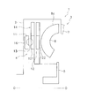
- FIG. 1 is a schematic diagram when a torque fluctuation suppressing device according to an embodiment of the present invention is mounted on a lock-up device of a torque converter.
- OO is the rotational axis of the torque converter.
- the torque converter 1 includes a front cover 2, a torque converter main body 3, a lockup device 4, and an output hub 5. Torque is input to the front cover 2 from the engine.
- the torque converter main body 3 includes an impeller 7 connected to the front cover 2, a turbine 8, and a stator (not shown).
- the turbine 8 is connected to the output hub 5, and an input shaft (not shown) of the transmission can be engaged with the inner peripheral portion of the output hub 5 by a spline.
- the lock-up device 4 has a clutch part, a piston that is operated by hydraulic pressure, and the like, and can take a lock-up on state and a lock-up off state.
- the lock-up on state the torque input to the front cover 2 is transmitted to the output hub 5 via the lock-up device 4 without passing through the torque converter body 3.
- the lock-up off state torque input to the front cover 2 is transmitted to the output hub 5 via the torque converter body 3.
- the lockup device 4 includes an input side rotating body 11, an output side rotating body 12, a damper 13, and a torque fluctuation suppressing device 14.
- the input side rotating body 11 includes a piston that is movable in the axial direction, and has a friction member 16 on the side surface on the front cover 2 side. When the friction member 16 is pressed against the front cover 2, torque is transmitted from the front cover 2 to the input side rotating body 11.
- the output-side rotator 12 includes a first hub (first rotator) 121 and a second hub (second rotator) 122 that are arranged to face each other in the axial direction.
- the first hub 121 is disposed so as to face the input side rotating body 11 in the axial direction, and is rotatable relative to the input side rotating body 11. Further, the first hub 121 and the second hub 122 are fixed to each other and rotate synchronously, and both are connected to the output hub 5.
- the damper 13 is disposed between the input side rotating body 11 and the first hub 121.
- the damper 13 has a plurality of torsion springs, and elastically connects the input side rotating body 11 and the first hub 121 in the rotational direction.
- the damper 13 transmits torque from the input side rotating body 11 to the first hub 121 and the second hub 122 and absorbs and attenuates torque fluctuations.
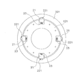
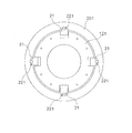
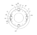
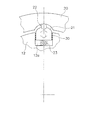
- FIG. 2A is a front view of the first hub 121 and the torque fluctuation suppressing device 14, and FIG. 3A is a front view of the second hub 122 and the torque fluctuation suppressing device 14. Moreover, a part of FIG. 2A is enlarged and shown in FIG.
- the torque fluctuation suppressing device 14 includes a first inertia ring 201 and a second inertia ring 202 that constitute the mass body 20, a plurality of centrifuges 21, and four first cam mechanisms 221.
- Four second cam mechanisms 222 and a plurality of coil springs 23 are provided.
- the centrifuge 21, the first and second cam mechanisms 221, 222, and the coil spring 23 are arranged at equal intervals of 90 ° in the circumferential direction.
- positioned at the inner peripheral side of each centrifuge 21 is also omissible.
- the coil spring 23 may be provided or omitted.
- the first inertia ring 201 is a plate having a predetermined thickness formed in a continuous annular shape, and is disposed on the outer peripheral side of the first hub 121 with a predetermined gap in the radial direction. That is, the first inertia ring 201 is disposed at the same position as the first hub 121 in the axial direction.
- the first inertia ring 201 has the same rotation axis as the rotation axis of the first hub 121, can rotate with the first hub 121, and can rotate relative to the first hub 121.
- the second inertia ring 202 has the same configuration as the first inertia ring 201. That is, it is formed in a continuous annular shape, arranged on the outer peripheral side of the second hub 122 with a predetermined gap in the radial direction, and arranged at the same position in the axial direction as the second hub 122.
- the second inertia ring 202 has the same rotation axis as the rotation axis of the second hub 122, can rotate with the second hub 122, and can rotate relative to the second hub 122.
- the centrifuge 21 is disposed on the first hub 121 and the second hub 122 and can be moved in the radial direction by the centrifugal force generated by the rotation of the first hub 121 and the second hub 122.
- the centrifuge provided in the first hub 121 will be described.
- the first hub 121 is provided with a recess 121a on the outer peripheral surface.
- the recess 121a is formed in a rectangular shape on the outer peripheral surface of the first hub 121 so as to be recessed toward the center of rotation on the inner peripheral side.
- the centrifuge 21 is inserted into the recess 121a so as to be movable in the radial direction.
- the centrifuge 21 and the recess 121a are set so that the friction coefficient between the side surface of the centrifuge 21 and the recess 121a is 0.1 or less.
- the centrifuge 21 is a plate having substantially the same thickness as the first hub 121, and the outer peripheral surface 21a is formed in an arc shape. Further, the outer peripheral surface 21a of the centrifuge 21 is formed with a roller accommodating portion 21b that is recessed inward.
- the first cam mechanism 221 includes a roller 25 as a cam follower and a cam 26 formed on the inner peripheral surface of the first inertia ring 201, as shown in FIG.
- the roller 25 is attached to the roller accommodating portion 21 b of the centrifuge 21 and is movable in the radial direction together with the centrifuge 21.
- the roller 25 may be rotatable or fixed in the roller accommodating portion 21b.
- the cam 26 is an arc-shaped surface with which the roller 25 abuts.
- the coil spring 23 is disposed between the bottom surface of the recess 12a and the inner peripheral surface of the centrifuge 21, and urges the centrifuge 21 to the outer peripheral side. Due to the urging force of the coil spring 23, the centrifuge 21 and the roller 25 are pressed against the cam 26 of the first inertia ring 201. Therefore, even when the centrifugal force is not acting on the centrifuge 21 with the first hub 121 not rotating, the roller 25 abuts against the cam 26.
- the second cam mechanism 222 is the same as the first cam mechanism 221 except for the shape of the cam 26.
- the first hub 121 and the first inertia ring 201 rotate in the state shown in FIG. That is, the roller 25 of the first cam mechanism 221 contacts the deepest position (circumferential center position) of the cam 26, and the rotational phase difference between the first hub 121 and the first inertia ring 201 is “0”. .
- the relative displacement in the rotational direction between the first hub 121 and the first inertia ring 201 is referred to as a “rotational phase difference”, which is shown in FIG. 4 and FIG. And the deviation between the center position of the roller 25 in the circumferential direction and the center position of the cam 26 in the circumferential direction.
- FIG. 5A shows a case where a rotational phase difference + ⁇ occurs on the + R side
- FIG. 5B shows a case where a rotational phase difference ⁇ occurs on the ⁇ R side.
- the first component force P1 is a force that moves the first hub 121 in the right direction in FIG. 5A via the first cam mechanism 221. That is, a force in the direction of reducing the rotational phase difference between the first hub 121 and the first inertia ring 201 acts on the first hub 121. Further, the centrifuge 21 and the roller 25 are moved to the radially inner peripheral side against the urging force of the coil spring 23 by the second component force P2.
- FIG. 5B shows a case where a rotational phase difference ⁇ is generated between the first hub 121 and the first inertia ring 201.
- the moving direction of the roller 25 of the first cam mechanism 221 and the reaction force P0 are shown.
- the operation is the same except that the directions of the first component force P1 and the second component force P2 are different from those in FIG.
- the first hub is caused by the centrifugal force acting on the centrifuge 21 and the action of the first cam mechanism 221.
- 121 receives a force (first component force P1) in a direction to reduce the rotational phase difference between the two. This force suppresses torque fluctuations.
- the force for suppressing the torque fluctuation described above varies depending on the centrifugal force, that is, the rotational speed of the first hub 121, and also varies depending on the rotational phase difference and the shape of the cam 26. Therefore, by appropriately setting the shape of the cam 26, the characteristics of the torque fluctuation suppressing device 14 can be made optimal characteristics according to the engine specifications and the like.
- the shape of the cam 26 can be made such that the first component force P1 changes linearly according to the rotational phase difference in the state where the same centrifugal force is acting.
- the shape of the cam 26 can be a shape in which the first component force P1 changes nonlinearly according to the rotational phase difference.
- the operation of the second cam mechanism 222 is basically the same as the operation of the first cam mechanism 221.
- the difference is the conversion characteristic from centrifugal force to circumferential force due to the difference in cam shape. That is, in the first cam mechanism 221, the cam 26 is formed with a relatively small radius of curvature.
- the cam of the second cam mechanism 222 is formed larger than the radius of curvature of the cam 26 of the first cam mechanism 221 as is apparent from FIGS. 3A and 3B.
- the centrifuge when the centrifuge receives a centrifugal force, it is converted into a circumferential force by the first conversion characteristic, but in the second cam mechanism 222, a second different from the first conversion characteristic. With the conversion characteristic, centrifugal force is converted into circumferential force.
- the first cam mechanism 221 has a first conversion characteristic
- the second cam mechanism 222 has a second conversion characteristic. Therefore, for example, when performing a two-cylinder deactivation in a four-cylinder engine, the first conversion characteristic suppresses torque fluctuation when the four cylinders are operating, and the second conversion characteristic causes only two cylinders to operate. It is possible to suppress the torque fluctuation during the operation.
- the anti-resonance frequency of the torque fluctuation suppressing device for four cylinders is 33.3 Hz
- the anti-resonance frequency of the torque fluctuation suppressing device for two cylinders is 16.7 Hz. is there. Therefore, the torque fluctuation is effectively suppressed at each anti-resonance point by the action of only one of the cam mechanisms.
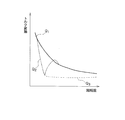
- FIG. 6 is a diagram illustrating an example of torque fluctuation suppression characteristics.
- the horizontal axis represents the rotational speed, and the vertical axis represents the torque fluctuation (rotational speed fluctuation).
- the characteristic Q1 is a case where a device for suppressing torque fluctuation is not provided
- the characteristic Q2 is a case where a conventional dynamic damper device is provided
- the characteristic Q3 is a case where the torque fluctuation suppressing device 14 of the present embodiment is provided. Show.
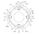
- Embodiment- 7 and 8 show a torque fluctuation suppressing device according to a second embodiment of the present invention.
- the first inertia ring 201 is partially broken.
- FIG. 8 is a partial plan view of FIG. Note that members that are the same as or correspond to those in the first embodiment are denoted by the same reference numerals even if the shapes and the like are different.
- the torque fluctuation suppressing device includes a first inertia ring 201, a second inertia ring 202, four centrifuges 21, two first cam mechanisms 221, and two second cam mechanisms. 222 and four coil springs 23.
- Each of the four centrifuges 21 and the cam mechanisms 221 and 222 is disposed at equal intervals of 90 ° in the circumferential direction.
- the coil spring 23 is provided, but the coil spring 23 may be omitted as described above.
- the first inertia ring 201 and the second inertia ring 202 are plates that have a predetermined thickness and are formed in a continuous annular shape.
- the first inertia ring 201 and the second inertia ring 202 are predetermined on the outer peripheral side of the output side rotary body 12 in the radial direction with the output side rotary body 12. It is arranged with a gap.
- the first inertia ring 201 and the second inertia ring 202 are disposed so as to face each other in the axial direction, and both have the same rotation axis as the rotation axis of the output-side rotator 12 and output. It can rotate with the side rotator 12 and can rotate relative to the output side rotator 12.
- the centrifuge 21 is disposed on the output-side rotator 12 and can be moved in the radial direction by the centrifugal force generated by the rotation of the output-side rotator 12.
- the relationship between the centrifuge 21 and the output-side rotator 12 and the configuration thereof are the same as those in the first embodiment. That is, a concave portion 12a is provided on the outer peripheral surface of the output side rotating body 12, and the centrifuge 21 is inserted into the concave portion 12a so as to be movable in the radial direction.
- the centrifuge 21 is a plate having substantially the same thickness as that of the output-side rotator 12, and a roller accommodating portion is formed on the outer peripheral surface.
- the first cam mechanism 221 has the same configuration as that of the first embodiment except for the number. That is, the two first cam mechanisms 221 are arranged at an interval of 180 ° in the circumferential direction, the roller 25 as a cam follower, the cam 26 formed on the inner peripheral surface of the first inertia ring 201, It is composed of
- the roller 25 is attached to the roller accommodating portion of the centrifuge 21 and is movable in the radial direction together with the centrifuge 21.
- the cam 26 is an arc-shaped surface with which the roller 25 abuts. When the output side rotating body 12 and the first inertia ring 201 are relatively rotated within a predetermined angle range, the roller 25 moves along the cam 26.
- the second cam mechanism 222 has the same configuration as that of the first embodiment except for the number. That is, the two second cam mechanisms 222 are arranged at an interval of 180 ° in the circumferential direction, the roller 25 as a cam follower, the cam 26 formed on the inner peripheral surface of the first inertia ring 201, It is composed of The first cam mechanism 221 is different from the first cam mechanism 221 only in the shape of the cam 26, and other configurations are the same as those of the first cam mechanism 221.
- a groove 201a having a predetermined length in the circumferential direction is formed in a portion where the second cam mechanism 222 is disposed.
- the outer peripheral surface of the groove 201 a is formed in an arc shape centering on the rotation center of the output side rotating body 12 and the first inertia ring 201. Therefore, even if the roller 25 as a cam follower moves in the groove 201a, it does not function as a cam mechanism.
- a similar groove 202a is formed on the inner peripheral surface of the second inertia ring 202, and even if the roller 25 moves in the groove 202a, it does not function as a cam mechanism.
- first and second cam mechanisms 221 and 222 Regarding the operation of the first and second cam mechanisms 221 and 222 (torque fluctuation suppression), the basic operation is the same as that of the first embodiment except that the number and arrangement of the cam mechanisms are different from those of the first embodiment. . Also in the second embodiment, as in the first embodiment, the force for suppressing the torque fluctuation varies depending on the centrifugal force, that is, the rotational speed of the output side rotating body 12, and depends on the rotational phase difference and the shape of the cam 26. Also changes. Therefore, by appropriately setting the shape of the cam 26, the characteristics of the torque fluctuation suppressing device can be made optimal characteristics according to the engine specifications and the like.
- the torque variation when the four cylinders are operating is caused by the first conversion characteristic of the first cam mechanism 221 as in the first embodiment. It is possible to suppress the torque fluctuation when only two cylinders are operating by the second conversion characteristic of the second cam mechanism 222.
- FIG. 9 shows a torque fluctuation suppressing device according to a third embodiment of the present invention. Note that members that are the same as or correspond to those in the first embodiment are denoted by the same reference numerals even if the shapes and the like are different.
- the torque fluctuation suppression device includes a first inertia ring 201 and a second inertia ring 202, four first centrifuges 211 and second centrifuges 212, and four first cam mechanisms 221, respectively. And four second cam mechanisms 222 and eight coil springs 23.
- Each of the four centrifuges 21 and the cam mechanisms 221 and 222 is disposed at equal intervals of 90 ° in the circumferential direction.
- the coil spring 23 is provided in the example shown in FIG. 9, the coil spring 23 may be omitted as described above.
- the first inertia ring 201 is a plate having a predetermined thickness formed in a continuous annular shape, and is arranged on the outer peripheral side of the output side rotary body 12 with a predetermined gap in the radial direction from the output side rotary body 12. Has been.
- the first inertia ring 201 has the same rotational axis as the rotational axis of the output-side rotator 12, can rotate with the output-side rotator 12, and can rotate relative to the output-side rotator 12.
- the second inertia ring 202 is a plate having a predetermined thickness formed in a continuous annular shape, and has a predetermined gap in the radial direction with the first inertia ring 201 further on the outer peripheral side of the first inertia ring 201. Has been placed.
- the second inertia ring 202 has the same rotation axis as the rotation axis of the output-side rotator 12 and the first inertia ring 201, can rotate together with the output-side rotator 12 and the first inertia ring 201, and the first inertia ring Rotating relative to 201 is possible.
- the first centrifuge 211 and the second centrifuge 212 are arranged in different locations, but have the same configuration and shape.
- the first centrifuge 211 is disposed on the output-side rotator 12 and is movable in the radial direction by a centrifugal force generated by the rotation of the output-side rotator 12.
- the second centrifuge 212 is disposed on the first inertia ring 201 and is movable in the radial direction by a centrifugal force generated by the rotation of the first inertia ring 201.
- the relationship between the centrifuges 211 and 212, the output-side rotator 12, and the first inertia ring 201 and the configuration thereof are the same as those in the first embodiment. That is, a recess 12a is provided on the outer peripheral surface of the output-side rotator 12, and the first centrifuge 211 is inserted into the recess 12a so as to be movable in the radial direction. Further, the first inertia ring 201 is formed with a recess 201a similar to the recess 12a of the output-side rotator 12, and a second centrifuge 212 is inserted into the recess 201a so as to be movable in the radial direction. Each centrifuge 211, 212 is a plate having substantially the same thickness as the output-side rotator 12, and a roller accommodating portion is formed on the outer peripheral surface.
- the first cam mechanism 221 has the same configuration as that of the first embodiment. That is, the four first cam mechanisms 221 are arranged at intervals of 90 ° in the circumferential direction, and the rollers 25 as cam followers, the cams 26 formed on the inner peripheral surface of the first inertia ring 201, It is composed of
- the roller 25 is attached to the roller accommodating portion of the first centrifuge 21 and is movable in the radial direction together with the first centrifuge 21.
- the cam 26 is an arc-shaped surface with which the roller 25 abuts. When the output side rotating body 12 and the first inertia ring 201 are relatively rotated within a predetermined angle range, the roller 25 moves along the cam 26.
- the second cam mechanism 222 has the same configuration as the first cam mechanism 221 except where it is arranged. That is, the four second cam mechanisms 222 are arranged at intervals of 90 ° in the circumferential direction, the roller 25 as a cam follower, the cam 26 formed on the inner peripheral surface of the second inertia ring 202, It is composed of In addition, although the shape of the cam 26 of the 1st cam mechanism 221 and the 2nd cam mechanism 222 is the same, the radial direction position in which the cam 26 was formed differs.
- first and second cam mechanisms 221 and 222 Regarding the operation of the first and second cam mechanisms 221 and 222 (torque fluctuation suppression), the basic operation is the same as in the first embodiment.
- the first cam mechanism 221 and the second cam mechanism 222 have the same shape of the cam 26, but the radial position where the second centrifuge 212 is arranged is the radial direction where the first centrifuge 211 is arranged. Greater than position. Therefore, when the rotation speed is the same, the centrifugal force acting on the roller 25 (cam follower: second centrifuge 212) of the second cam mechanism 212 is applied to the roller 25 (first centrifuge 211) of the first cam mechanism 211. Greater than the acting centrifugal force. Therefore, at the same rotation speed, the torque fluctuation suppressing force by the second cam mechanism 212 is larger than that by the first cam mechanism 211.
- the force for suppressing the torque fluctuation varies depending on the centrifugal force, that is, the rotation speed of the output-side rotator 12, and the rotational phase difference and the cam 26 It also changes depending on the shape. Therefore, by appropriately setting the shape of the cam 26, the characteristics of the torque fluctuation suppressing device can be made optimal characteristics according to the engine specifications and the like.
- the first cam mechanism 221 suppresses torque fluctuation when the four cylinders are operating, and the second The cam mechanism 222 can suppress torque fluctuation when only two cylinders are operating.
- FIG. 10 shows a torque fluctuation suppressing device according to the fourth embodiment.
- the mass body is configured by a continuous annular member.
- the mass body is formed by a plurality of divided inertia bodies 201 and 202 arranged side by side in the circumferential direction. It is configured.
- the configurations of the other output side rotator 12, the centrifuge 21 and the like are the same as those of the other embodiments.
- the mass body is constituted by two first inertia bodies 201 and second inertia bodies 202, respectively.
- the two first inertia bodies 201 are arranged to face each other with the rotation axis therebetween, and the two second inertia bodies 202 are similarly arranged to face each other with the rotation axis interposed therebetween.
- the first inertia body 201 and the second inertia body 202 are arranged at positions shifted by 90 °.
- a holding ring 203 for holding the inertia bodies 201 and 202 in the radial direction is provided on the outer peripheral side of the inertia bodies 201 and 202.
- a cam 26 having the same shape as the first inertia ring 201 of the first embodiment is formed on the inner peripheral surface of the first inertia body 201.
- a cam 26 having the same shape as the second inertia ring 202 of the first embodiment is formed on the inner peripheral surface of the second inertia body 202.
- the first cam mechanism 221 and the second cam mechanism 222 are constituted by a roller 25 as a cam follower provided on the outer peripheral surface of the centrifuge 21 and a cam 26 formed on the inner peripheral surfaces of the inertia bodies 201 and 202. And are configured.
- the operation of the first cam mechanism 221 and the second cam mechanism 222 is the same as that of the first embodiment except that the inertia amounts of the first and second inertia bodies 201 and 202 are small. Also according to the fourth embodiment, it is possible to obtain the same operational effects as the respective embodiments.
- FIG. 11 shows a torque fluctuation suppressing device according to the fifth embodiment.
- members that are the same as or correspond to those in the first embodiment are denoted by the same reference numerals even if the shapes and the like are different.
- two first cam mechanisms 221 and two second cam mechanisms 222 are arranged on the same circumference.
- the first cam mechanism 221 has the same configuration as the first cam mechanism 221 of the first embodiment. Further, the recess 12a is formed in the output-side rotator 12, and the configuration in which the centrifuge 21 is disposed so as to be movable in the radial direction in the recess 12a and the configuration of the centrifuge 21 are the same as those in the above embodiments. is there.
- the second cam mechanism 222 has the same configuration as the first cam mechanism 221 except that the operation prohibiting mechanism 27 is provided. That is, the second cam mechanism 222 has a roller 25 as a cam follower and a cam 26 formed on the inner peripheral surface of the inertia ring 20.
- the operation prohibiting mechanism 27 is disposed so as to face the rotation axis. That is, of the four centrifuges 21, the movement of the two opposing centrifuges 21 in the radial direction is restricted, and the operation of the second cam mechanism 222 is restricted.
- the operation prohibiting mechanism 27 holds the pair of rotating members 281 and 282 and the pair of rotating members 281 and 282 in an operation allowable posture as shown in FIG. And torsion springs 29a and 29b.
- the pair of rotating members 281 and 282 are arranged so as to sandwich the centrifuge 21 in the circumferential direction.
- the pair of rotating members 281 and 282 are arranged symmetrically with respect to the centrifuge 21.
- One rotating member 281 is rotatably supported by a pin 30 fixed to the output side rotating body 12. That is, the rotation member 281 is rotatable around the pin 30 in parallel with the side surface of the output side rotating body 12.
- the rotating member 281 has a claw portion 281a on the centrifuge 21 side of the pin 30 and a weight portion 281b on the opposite side.
- the claw portion 281 a is formed to have a length that can contact the outer peripheral surface of the centrifuge 21.
- the other rotation member 282 is also the same structure, and has the nail
- the pair of rotating members 281 and 282 are held in an allowable posture as shown in FIG. That is, the claw portions 281a and 282a of the pair of rotating members 281 and 282 face the outer peripheral side, and the centrifuge 21 is freely movable in the radial direction.
- the centrifugal force acting on the weight portions 281b and 282b of the pair of rotating members 281 and 282 is changed to the centrifugal force acting on the centrifuge 21 and the torsion spring 29a. , 29b.
- the weight portions 281b and 282b of the pair of rotating members 281 and 282 move to the outer peripheral side, and the claw portions 281a and 282a move to the inner peripheral side.
- the centrifuge 21 is prohibited from moving in the radial direction by the claw portions 281a and 282a. Therefore, the roller 25 as the cam follower provided in the centrifuge 21 cannot contact the cam 26, and the second cam mechanism 222 does not operate.
- both the first cam mechanism 221 and the second cam mechanism 222 operate.
- the output-side rotator 12 reaches a predetermined number of revolutions or more, only the first cam mechanism 221 operates and the second cam mechanism 222 does not operate. Therefore, if the shapes of the cams 26 and the rotating members 281 and 282 of the two cam mechanisms 221 and 222 are appropriately set according to the engine specifications and the like, torque fluctuation can be effectively suppressed.
- FIG. 1 A sixth embodiment is shown in FIG.
- two first cam mechanisms 221 and two second cam mechanisms 222 are arranged on one output-side rotator 12 and one inertia ring 20. Since the configuration of each cam mechanism 221, 222 is the same as that of the first embodiment, it is omitted here.
- the characteristic for suppressing the torque fluctuation is a characteristic obtained by synthesizing the first cam mechanism 221 and the second cam mechanism 222 unlike the first embodiment.
- the inertia ring constituting the torque fluctuation suppressing device may be connected to the turbine 8.
- the turbine 8 is not connected to the output hub 5.
- the turbine shell 8a since the inertia ring is connected to the turbine 8 (more precisely, the turbine shell 8a), the turbine shell 8a also functions as an inertia (inertial body) together with the inertia ring.
- a member that reduces friction such as a roller, a resin race, or a sheet may be disposed between the centrifuge 21 and the recess 12a.
- FIG. 16 is a diagram schematically showing a torque converter.
- the torque converter includes an input-side rotating body 71, an output-side rotating body 72, and a damper provided between the rotating bodies 71 and 72. 73.
- the input-side rotator 71 includes members such as a front cover, a drive plate, and a piston.
- the output side rotating body 72 includes a driven plate and a turbine hub.
- the damper 73 includes a plurality of torsion springs.
- a centrifuge is provided in any of the rotating members that constitute the input-side rotator 71, and a cam mechanism 74 that operates by utilizing the centrifugal force acting on the centrifuge is provided. It has been. About the cam mechanism 74, the structure similar to the structure shown by the said each embodiment is applicable.
- the torque converter shown in FIG. 17 is provided with a centrifuge in any of the rotating members constituting the output-side rotator 72, and a cam mechanism that operates by utilizing the centrifugal force acting on the centrifuge. 74 is provided. About the cam mechanism 74, the structure similar to the structure shown by the said each embodiment is applicable.
- the torque converter shown in FIG. 18 has another damper 75 and an intermediate member 76 provided between the two dampers 73 and 75 in addition to the configuration shown in FIGS. is doing.
- the intermediate member 76 is relatively rotatable with the input-side rotator 71 and the output-side rotator 72, and causes the two dampers 73 and 75 to act in series.
- the intermediate member 76 is provided with a centrifuge, and a cam mechanism 74 that operates using a centrifugal force acting on the centrifuge is provided.
- a cam mechanism 74 that operates using a centrifugal force acting on the centrifuge is provided.
- the cam mechanism 74 the structure similar to the structure shown by the said each embodiment is applicable.
- the torque converter shown in FIG. 19 has a float member 77.
- the float member 77 is a member for supporting the torsion spring constituting the damper 73, and is formed, for example, in an annular shape so as to cover the outer periphery and at least one side surface of the torsion spring.
- the float member 77 is relatively rotatable with the input-side rotator 71 and the output-side rotator 72, and rotates around the damper 73 by friction with the torsion spring of the damper 73. That is, the float member 77 also rotates.
- the float member 77 is provided with a centrifuge 78, and a cam mechanism 74 that operates using a centrifugal force acting on the centrifuge 78 is provided.
- a cam mechanism 74 that operates using a centrifugal force acting on the centrifuge 78 is provided.
- the cam mechanism 74 the structure similar to the structure shown by the said each embodiment is applicable.
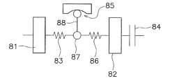
- FIG. 20 is a schematic diagram of a power transmission device having a flywheel 80 having two inertia bodies 81 and 82 and a clutch device 84. That is, the flywheel 80 disposed between the engine and the clutch device 84 includes a first inertial body 81, a second inertial body 82 disposed so as to be rotatable relative to the first inertial body 81, and two inertial bodies. And a damper 83 disposed between 81 and 82.
- the second inertia body 82 also includes a clutch cover that constitutes the clutch device 84.
- a centrifuge is provided in one of the rotating members constituting the second inertial body 82, and a cam mechanism 85 that operates by utilizing the centrifugal force acting on the centrifuge is provided. ing. About the cam mechanism 85, the structure similar to the structure shown by the said each embodiment is applicable.
- FIG. 21 is an example in which a centrifuge is provided in the first inertial body 81 in the same power transmission device as that in FIG.
- a cam mechanism 85 that operates using centrifugal force acting on the centrifuge is provided.
- the structure similar to the structure shown by the said each embodiment is applicable.
- the power transmission device shown in FIG. 22 includes another damper 86 and an intermediate member 87 provided between the two dampers 83, 86. Have.
- the intermediate member 87 is rotatable relative to the first inertial body 81 and the second inertial body 82.
- the intermediate member 87 is provided with a centrifuge 88, and a cam mechanism 85 that operates using a centrifugal force acting on the centrifuge 88 is provided.
- a cam mechanism 85 that operates using a centrifugal force acting on the centrifuge 88 is provided.
- the cam mechanism 85 the structure similar to the structure shown by the said each embodiment is applicable.
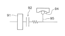
- FIG. 23 is a schematic diagram of a power transmission device in which a clutch device is provided on one flywheel.
- the first inertial body 91 in FIG. 23 includes one flywheel and a clutch cover of the clutch device 92.
- a centrifuge is provided on any of the rotating members that constitute the first inertial body 91, and a cam mechanism 94 that operates using a centrifugal force acting on the centrifuge is provided.
- the cam mechanism 94 the same configuration as that shown in each of the above embodiments can be applied.
- FIG. 24 is an example in which a centrifuge 95 is provided on the output side of the clutch device 92 in the same power transmission device as FIG.
- a cam mechanism 94 is provided that operates by utilizing the centrifugal force acting on the centrifuge 95.
- the same configuration as that shown in each of the above embodiments can be applied.
- the torque fluctuation suppressing device of the present invention may be disposed on any of the rotating members constituting the transmission, and further, the shaft (propeller shaft or drive) on the output side of the transmission (Shaft).
- the torque fluctuation suppressing device of the present invention may be further applied to a conventionally known dynamic damper device or a power transmission device provided with a pendulum type damper device.
- the peak of the torque fluctuation can be suppressed in a relatively wide rotational speed range.
Landscapes
- Engineering & Computer Science (AREA)
- General Engineering & Computer Science (AREA)
- Mechanical Engineering (AREA)
- Physics & Mathematics (AREA)
- Acoustics & Sound (AREA)
- Aviation & Aerospace Engineering (AREA)
- One-Way And Automatic Clutches, And Combinations Of Different Clutches (AREA)
- Vibration Dampers (AREA)
Abstract
Description
トルクコンバータ1は、フロントカバー2と、トルクコンバータ本体3と、ロックアップ装置4と、出力ハブ5と、を有している。フロントカバー2にはエンジンからトルクが入力される。トルクコンバータ本体3は、フロントカバー2に連結されたインペラ7と、タービン8と、ステータ(図示せず)と、を有している。タービン8は出力ハブ5に連結されており、出力ハブ5の内周部には、トランスミッションの入力軸(図示せず)がスプラインによって係合可能である。
ロックアップ装置4は、クラッチ部や、油圧によって作動するピストン等を有し、ロックアップオン状態と、ロックアップオフ状態と、を取り得る。ロックアップオン状態では、フロントカバー2に入力されたトルクは、トルクコンバータ本体3を介さずに、ロックアップ装置4を介して出力ハブ5に伝達される。一方、ロックアップオフ状態では、フロントカバー2に入力されたトルクは、トルクコンバータ本体3を介して出力ハブ5に伝達される。
-第1実施形態-
図2Aは第1ハブ121及びトルク変動抑制装置14の正面図、図3Aは第2ハブ122及びトルク変動抑制装置14の正面図である。また、図2Aの一部を拡大して図4に示している。これらの図に示すように、トルク変動抑制装置14は、質量体20を構成する第1イナーシャリング201及び第2イナーシャリング202と、複数の遠心子21と、4個の第1カム機構221と、4個の第2カム機構222と、複数のコイルスプリング23と、を有している。遠心子21、第1及び第2カム機構221,222、及びコイルスプリング23は、それぞれ円周方向に90°の等間隔で配置されている。
図4及び図5を用いて、第1カム機構221の作動(トルク変動の抑制)について説明する。ロックアップオン時には、フロントカバー2に伝達されたトルクは、入力側回転体11及びダンパ13を介して第1ハブ121及び第2ハブ122に伝達される。
第2カム機構222の作動については、第1カム機構221の作動と基本的に同じである。異なるのは、カム形状の相違による、遠心力から円周方向力への変換特性である。すなわち、第1カム機構221では、カム26は曲率半径が比較的小さく形成されている。これに対して第2カム機構222のカムは、図3A及び図3Bから明らかなように、第1カム機構221のカム26の曲率半径に比較して大きく形成されている。このため、第1カム機構221では、遠心子が遠心力を受けたときには第1変換特性で円周方向力に変換されるが、第2カム機構222では、第1変換特性とは異なる第2変換特性で、遠心力が円周方向力に変換される。
以上のように、第1カム機構221は第1変換特性を有し、第2カム機構222は第2変換特性を有している。したがって、例えば4気筒エンジンで2気筒の気筒休止を行う場合に、第1変換特性によって、4気筒が作動している際のトルク変動を抑制し、第2変換特性によって、2気筒のみが作動している際のトルク変動を抑制するようにすることができる。
図6は、トルク変動抑制特性の一例を示す図である。横軸は回転数、縦軸はトルク変動(回転速度変動)である。特性Q1はトルク変動を抑制するための装置が設けられていない場合、特性Q2は従来のダイナミックダンパ装置が設けられた場合、特性Q3は本実施形態のトルク変動抑制装置14が設けられた場合を示している。
図7及び図8は、本発明の第2実施形態によるトルク変動抑制装置を示している。図7では、第1イナーシャリング201を部分的に破断して示している。図8は、図7の平面部分図である。なお、第1実施形態と同じ又は対応する部材には、形状等は異なる場合であっても、同じ符合を付して示している。
第1及び第2カム機構221,222の作動(トルク変動の抑制)については、カム機構の個数及び配置が第1実施形態と異なるだけで、基本的な作動は第1実施形態と同様である。この第2実施形態においても、第1実施形態と同様に、トルク変動を抑制する力は、遠心力、すなわち出力側回転体12の回転数によって変化するし、回転位相差及びカム26の形状によっても変化する。したがって、カム26の形状を適宜設定することによって、トルク変動抑制装置の特性を、エンジン仕様等に応じた最適な特性にすることができる。
図9は本発明の第3実施形態によるトルク変動抑制装置を示している。なお、第1実施形態と同じ又は対応する部材には、形状等は異なる場合であっても、同じ符合を付して示している。
第1及び第2カム機構221,222の作動(トルク変動の抑制)については、基本的な作動は第1実施形態と同様である。なお、第1カム機構221と第2カム機構222とは、カム26の形状は同じであるが、第2遠心子212の配置された径方向位置は第1遠心子211の配置された径方向位置より大きい。したがって、同じ回転数の場合、第2カム機構212のコロ25(カムフォロア:第2遠心子212)に作用する遠心力の方が、第1カム機構211のコロ25(第1遠心子211)に作用する遠心力より大きい。したがって、同じ回転数では、第2カム機構212によるトルク変動の抑制力の方が、第1カム機構211によるそれよりも大きくなる。
図10に第4実施形態によるトルク変動抑制装置を示している。なお、第1実施形態と同じ又は対応する部材には、形状等は異なる場合であっても、同じ符合を付して示している。前記各実施形態では、質量体を連続した円環状の部材で構成したが、この第4実施形態では、質量体は、円周方向に並べて配置された複数の分割されたイナーシャ体201,202によって構成されている。他の出力側回転体12、遠心子21等の構成は他の実施形態と同様である。
図11に第5実施形態によるトルク変動抑制装置を示している。なお、第1実施形態と同じ又は対応する部材には、形状等は異なる場合であっても、同じ符合を付して示している。第5実施形態では、第4実施形態と同様に、2つの第1カム機構221と、2つの第2カム機構222と、が同じ円周上に配置されている。
第6実施形態を図13に示す。この第6実施形態は、1つの出力側回転体12及び1つのイナーシャリング20に、2つの第1カム機構221と、2つの第2カム機構222と、を配置したものである。各カム機構221,222の構成は、第1実施形態と同様であるので、ここでは省略する。なお、この第6実施形態では、トルク変動を抑制するための特性は、第1実施形態とは異なり、第1カム機構221と第2カム機構222とを合成した特性となる。
本発明は以上のような実施形態に限定されるものではなく、本発明の範囲を逸脱することなく種々の変形又は修正が可能である。
以上のようなトルク変動抑制装置を、トルクコンバータや他の動力伝達装置に適用する場合、種々の配置が可能である。以下に、トルクコンバータや他の動力伝達装置の模式図を利用して、具体的な適用例について説明する。なお、以下の各例を示す図において、カム機構を簡略して示しているが、各カム機構のすべてにおいて、前述の各実施形態におけるカム機構を適用する事が可能である。
11 入力側回転体
12 出力側回転体
121 第1ハブ
122 第2ハブ
14 トルク変動抑制装置
20 イナーシャリング(質量体)
201 第1イナーシャリング
202 第2イナーシャリング
21 遠心子
22 カム機構
221 第1カム機構
222 第2カム機構
23 コイルスプリング(付勢部材)
25 コロ(カムフォロア)
26 カム
73,75,83,86 ダンパ
76,87 中間部材
77 フロート部材
80 フライホイール
81,82,91 慣性体
84,92 クラッチ装置
Claims (20)
- トルクが入力される回転体のトルク変動を抑制するためのトルク変動抑制装置であって、
前記回転体とともに回転可能であり、かつ前記回転体に対して相対回転自在に配置された質量体と、
前記回転体及び前記質量体の回転による遠心力を受けるように配置された第1遠心子及び第2遠心子と、
前記第1遠心子に作用する遠心力を受けて、前記回転体と前記質量体との間に回転方向における相対変位が生じたときには、前記遠心力を、前記相対変位が小さくなる方向の第1円周方向力に変換する第1カム機構と、
前記第2遠心子に作用する遠心力を受けて、前記回転体と前記質量体との間に回転方向における相対変位が生じたときには、前記遠心力を、前記相対変位が小さくなる方向の第2円周方向力に変換する第2カム機構と、
を備えたトルク変動抑制装置。 - 前記回転体は、軸方向第1位置に配置された第1回転体と、軸方向第2位置に配置された第2回転体と、を有し、
前記質量体は、前記第1回転体の外周又は内周に配置された第1イナーシャリングと、前記第2回転体の外周又は内周に配置された第2イナーシャリングと、を有し、
前記第1遠心子は前記第1回転体又は前記第1イナーシャリングに径方向に移動自在に支持され、
前記第2遠心子は前記第2回転体又は前記イナーシャリングに径方向に移動自在に支持され、
前記第1カム機構は軸方向において前記軸方向第1位置に配置され、
前記第2カム機構は軸方向において前記軸方向第2位置に配置されている、
請求項1に記載のトルク変動抑制装置。 - 前記第1遠心子は前記回転体又は前記質量体における円周方向第1位置に配置され、
前記第2遠心子は前記回転体又は前記質量体における円周方向第2位置に配置され、
前記第1カム機構は前記円周方向第1位置に配置され、
前記第2カム機構は前記円周方向第2位置に配置されている、
請求項1に記載のトルク変動抑制装置。 - 前記質量体は、前記回転体の外周に配置された第1イナーシャリングと、前記第1イナーシャリングのさらに外周に配置された第2イナーシャリングと、を有し、
前記第1遠心子は前記回転体に径方向に移動自在に支持され、
前記第2遠心子は前記第1イナーシャリングに径方向に移動自在に支持され、
前記第1カム機構は前記回転体の外周で前記第1イナーシャリングの内周に配置され、
前記第2カム機構は前記第1イナーシャリングの外周で前記第2イナーシャリングの内周に配置されている、
請求項1に記載のトルク変動抑制装置。 - 前記第2カム機構は、前記回転体又は前記質量体が所定回転数以上では前記第2遠心子の径方向外側への移動を規制する作動禁止機構を有し、前記作動禁止機構の作動によって前記第2遠心子に作用する遠心力を円周方向力に変換させない、請求項1に記載のトルク変動抑制装置。
- 前記回転体は外周面に凹部を有し、
前記第1及び第2遠心子の少なくとも一方は、前記凹部に径方向に移動自在に収容されている、
請求項1から5のいずれかに記載のトルク変動抑制装置。 - 前記第1及び第2遠心子のうち前記凹部内に収容された遠心子と前記凹部との間の摩擦係数は0.1以下である、
請求項6に記載のトルク変動抑制装置。 - 前記凹部内に収容された遠心子が移動する方向の前記遠心子の側面と前記凹部との間には、前記遠心子が移動する際の摩擦を低減するための摩擦低減部材が配置されている、請求項7に記載のトルク変動抑制装置。
- 前記第1カム機構及び前記第2カム機構は、
前記第1遠心子及び前記第2遠心子に設けられたカムフォロアと、
外周側に配置された前記回転体又は前記質量体の内周面に形成され、前記カムフォロアが当接し前記回転体と前記質量体との間の回転方向における相対変位量に応じて前記円周方向力が変化するような形状を有するカムと、
を有する、
請求項6から8のいずれかに記載のトルク変動抑制装置。 - 前記凹部内に配置され、前記回転体及び前記質量体が回転していない状態で前記カムと前記カムフォロアとが互いに当接するように前記第1遠心子及び第2遠心子の少なくとも一方を径方向外方に付勢する付勢部材をさらに備えた、請求項9に記載のトルク変動抑制装置。
- 前記質量体は連続した円環状に形成されている、請求項1から10のいずれかに記載のトルク変動抑制装置。
- エンジンとトランスミッションとの間に配置されるトルクコンバータであって、
前記エンジンからのトルクが入力される入力側回転体と、
前記トランスミッションにトルクを出力する出力側回転体と、
前記入力側回転体と前記タービンとの間に配置されたダンパと、
請求項1から11のいずれかに記載のトルク変動抑制装置と、
を備えたトルクコンバータ。 - 前記トルク変動抑制装置は前記入力側回転体に配置されている、請求項12に記載のトルクコンバータ。
- 前記トルク変動抑制装置は前記出力側回転体に配置されている、請求項12に記載のトルクコンバータ。
- 前記ダンパは、
前記入力側回転体からトルクが入力される第1ダンパと、
前記出力側回転体にトルクを出力する第2ダンパと、
前記第1ダンパと前記第2ダンパとの間に設けられた中間部材と、
を有し、
前記トルク変動抑制装置は前記中間部材に配置されている、
請求項12に記載のトルクコンバータ。 - 前記ダンパは複数のコイルスプリングを有し、
前記入力側回転体及び前記出力側回転体に対して相対回転自在であり、前記複数のコイルスプリングを支持するフロート部材をさらに備え、
前記トルク変動抑制装置は前記フロート部材に配置されている、
請求項12に記載のトルクコンバータ。 - 回転軸を中心に回転する第1慣性体と、前記回転軸を中心に回転し前記第1慣性体と相対回転自在な第2慣性体と、前記第1慣性体と前記第2慣性体との間に配置されたダンパと、を有するフライホイールと、
前記フライホイールの前記第2慣性体に設けられたクラッチ装置と、
請求項1から11のいずれかに記載のトルク変動抑制装置と、
を備えた動力伝達装置。 - 前記トルク変動抑制装置は前記第2慣性体に配置されている、請求項17に記載の動力伝達装置。
- 前記トルク変動抑制装置は前記第1慣性体に配置されている、請求項17に記載の動力伝達装置。
- 前記ダンパは、
前記第1慣性体からトルクが入力される第1ダンパと、
前記第2慣性体にトルクを出力する第2ダンパと、
前記第1ダンパと前記第2ダンパとの間に設けられた中間部材と、
を有し、
前記トルク変動抑制装置は前記中間部材に配置されている、
請求項17に記載の動力伝達装置
Priority Applications (4)
| Application Number | Priority Date | Filing Date | Title |
|---|---|---|---|
| US15/576,776 US10626949B2 (en) | 2015-08-20 | 2016-07-22 | Torque fluctuation inhibiting device, torque converter and power transmission device |
| CN201680047359.1A CN107923483B (zh) | 2015-08-20 | 2016-07-22 | 扭矩变动抑制装置、扭矩转换器及动力传递装置 |
| KR1020177037040A KR20180044234A (ko) | 2015-08-20 | 2016-07-22 | 토크 변동 억제 장치, 토크 컨버터 및 동력 전달 장치 |
| DE112016003043.6T DE112016003043T5 (de) | 2015-08-20 | 2016-07-22 | Drehmomentschwankungs-Verhinderungsvorrichtung, Drehmomentwandler und Kraftübertragungsvorrichtung |
Applications Claiming Priority (8)
| Application Number | Priority Date | Filing Date | Title |
|---|---|---|---|
| JP2015162957A JP6653538B2 (ja) | 2015-08-20 | 2015-08-20 | トルク変動抑制装置、トルクコンバータ、及び動力伝達装置 |
| JP2015-162957 | 2015-08-20 | ||
| JP2015-198244 | 2015-10-06 | ||
| JP2015198244A JP6656868B2 (ja) | 2015-10-06 | 2015-10-06 | トルク変動抑制装置、トルクコンバータ、及び動力伝達装置 |
| JP2015-199308 | 2015-10-07 | ||
| JP2015199308A JP6539180B2 (ja) | 2015-10-07 | 2015-10-07 | トルク変動抑制装置、トルクコンバータ、及び動力伝達装置 |
| JP2015-208759 | 2015-10-23 | ||
| JP2015208759A JP6577823B2 (ja) | 2015-10-23 | 2015-10-23 | トルク変動抑制装置、トルクコンバータ、及び動力伝達装置 |
Publications (1)
| Publication Number | Publication Date |
|---|---|
| WO2017029939A1 true WO2017029939A1 (ja) | 2017-02-23 |
Family
ID=58050955
Family Applications (4)
| Application Number | Title | Priority Date | Filing Date |
|---|---|---|---|
| PCT/JP2016/071332 Ceased WO2017029931A1 (ja) | 2015-08-20 | 2016-07-21 | トルク変動抑制装置、トルクコンバータ、及び動力伝達装置 |
| PCT/JP2016/071333 Ceased WO2017029932A1 (ja) | 2015-08-20 | 2016-07-21 | トルク変動抑制装置、トルクコンバータ、及び動力伝達装置 |
| PCT/JP2016/071503 Ceased WO2017029939A1 (ja) | 2015-08-20 | 2016-07-22 | トルク変動抑制装置、トルクコンバータ、及び動力伝達装置 |
| PCT/JP2016/071504 Ceased WO2017029940A1 (ja) | 2015-08-20 | 2016-07-22 | トルク変動抑制装置、トルクコンバータ、及び動力伝達装置 |
Family Applications Before (2)
| Application Number | Title | Priority Date | Filing Date |
|---|---|---|---|
| PCT/JP2016/071332 Ceased WO2017029931A1 (ja) | 2015-08-20 | 2016-07-21 | トルク変動抑制装置、トルクコンバータ、及び動力伝達装置 |
| PCT/JP2016/071333 Ceased WO2017029932A1 (ja) | 2015-08-20 | 2016-07-21 | トルク変動抑制装置、トルクコンバータ、及び動力伝達装置 |
Family Applications After (1)
| Application Number | Title | Priority Date | Filing Date |
|---|---|---|---|
| PCT/JP2016/071504 Ceased WO2017029940A1 (ja) | 2015-08-20 | 2016-07-22 | トルク変動抑制装置、トルクコンバータ、及び動力伝達装置 |
Country Status (5)
| Country | Link |
|---|---|
| US (4) | US10184542B2 (ja) |
| KR (4) | KR20180042163A (ja) |
| CN (4) | CN107923481B (ja) |
| DE (4) | DE112016003113T5 (ja) |
| WO (4) | WO2017029931A1 (ja) |
Cited By (1)
| Publication number | Priority date | Publication date | Assignee | Title |
|---|---|---|---|---|
| US10760644B2 (en) | 2016-07-19 | 2020-09-01 | Exedy Corporation | Dynamic vibration absorber |
Families Citing this family (28)
| Publication number | Priority date | Publication date | Assignee | Title |
|---|---|---|---|---|
| WO2017029931A1 (ja) * | 2015-08-20 | 2017-02-23 | 株式会社エクセディ | トルク変動抑制装置、トルクコンバータ、及び動力伝達装置 |
| JP6534589B2 (ja) * | 2015-09-11 | 2019-06-26 | 株式会社エクセディ | トルク変動抑制装置、トルクコンバータ、及び動力伝達装置 |
| KR101803953B1 (ko) * | 2016-05-27 | 2017-12-01 | 한국파워트레인 주식회사 | 차량용 토크 컨버터 |
| JP6827311B2 (ja) | 2016-12-12 | 2021-02-10 | 株式会社エクセディ | ダンパ装置 |
| JP2018132159A (ja) * | 2017-02-17 | 2018-08-23 | 株式会社エクセディ | トルク変動抑制装置、トルクコンバータ、及び動力伝達装置 |
| CN110494672A (zh) * | 2017-04-28 | 2019-11-22 | 爱信艾达株式会社 | 振动衰减装置 |
| JP2019039456A (ja) * | 2017-08-23 | 2019-03-14 | 株式会社エクセディ | トルク変動抑制装置、トルクコンバータ、及び動力伝達装置 |
| JP6709765B2 (ja) * | 2017-09-15 | 2020-06-17 | 株式会社エクセディ | トルク変動抑制装置、トルクコンバータ、及び動力伝達装置 |
| US11512766B2 (en) | 2017-09-28 | 2022-11-29 | Aisin Corporation | Vibration damping apparatus |
| JP2019100523A (ja) * | 2017-12-07 | 2019-06-24 | アイシン精機株式会社 | ダンパ装置 |
| US10612636B2 (en) * | 2018-03-01 | 2020-04-07 | Martin W. ChANCE | Hydraulic torque converter |
| JP7096068B2 (ja) * | 2018-05-28 | 2022-07-05 | 株式会社エフ・シー・シー | 遠心クラッチ |
| JP7047683B2 (ja) * | 2018-09-14 | 2022-04-05 | トヨタ自動車株式会社 | 捩り振動低減装置 |
| JP7263066B2 (ja) | 2019-03-13 | 2023-04-24 | 株式会社エクセディ | トルク変動抑制装置、及びトルクコンバータ |
| JP7300284B2 (ja) * | 2019-03-13 | 2023-06-29 | 株式会社エクセディ | トルク変動抑制装置、及びトルクコンバータ |
| JP2021025568A (ja) * | 2019-08-02 | 2021-02-22 | 株式会社エクセディ | 回転装置及びその芯出し構造 |
| JP7376291B2 (ja) * | 2019-09-13 | 2023-11-08 | 株式会社エクセディ | トルク変動抑制装置、及び動力伝達装置 |
| DE102019129842A1 (de) * | 2019-10-10 | 2021-04-15 | Schaeffler Technologies AG & Co. KG | Drehmomentübertragungsvorrichtung |
| CN110748602A (zh) * | 2019-11-06 | 2020-02-04 | 西南石油大学 | 一种两级离心式变转动惯量的储能飞轮 |
| IT201900024217A1 (it) * | 2019-12-17 | 2021-06-17 | Engines Eng S R L | Frizione centrifuga. |
| US11927254B2 (en) * | 2020-07-07 | 2024-03-12 | Exedy Corporation | Rotary device and power transmission device |
| CN112096826B (zh) * | 2020-11-09 | 2021-02-09 | 简俭科技(宁波)有限公司 | 单轨n针型扭矩吸吐器 |
| CN112096827B (zh) * | 2020-11-09 | 2021-02-02 | 简俭科技(宁波)有限公司 | n轨n针型扭矩吸吐器 |
| US11761523B2 (en) * | 2021-02-15 | 2023-09-19 | Exedy Corporation | Rotary device and power transmission device |
| CN112594349B (zh) * | 2021-03-08 | 2021-05-25 | 简俭科技(宁波)有限公司 | 径向型扭矩吸吐器 |
| CN113208485B (zh) * | 2021-05-18 | 2022-07-08 | 泉州沃科电器有限公司 | 一种升降微调式智能马桶 |
| CN113738820A (zh) * | 2021-11-03 | 2021-12-03 | 杭州高卡机械有限公司 | 基于弹针机构的扭矩吸吐器 |
| CN116040194B (zh) * | 2023-01-04 | 2025-07-15 | 宁夏天地西北煤机有限公司 | 增惯组件、带式输送机及输送系统 |
Citations (2)
| Publication number | Priority date | Publication date | Assignee | Title |
|---|---|---|---|---|
| JPH1182628A (ja) * | 1997-09-12 | 1999-03-26 | Exedy Corp | ダイナミックダンパー及びフライホイール組立体 |
| JP2014145413A (ja) * | 2013-01-29 | 2014-08-14 | Toyota Motor Corp | 捩り振動減衰装置 |
Family Cites Families (36)
| Publication number | Priority date | Publication date | Assignee | Title |
|---|---|---|---|---|
| US1929206A (en) | 1930-04-30 | 1933-10-03 | Continental Motors Corp | Engine |
| US2079226A (en) * | 1930-12-19 | 1937-05-04 | Sarazin Kaoul Reland Raymond | Means adapted to reduce the torsional oscillations of crankshafts |
| US3578822A (en) * | 1969-08-12 | 1971-05-18 | Fmc Corp | Dynamically balanced power transmission |
| US3730013A (en) | 1969-08-12 | 1973-05-01 | Fmc Corp | Dynamically balanced power transmission |
| JPH01312246A (ja) | 1988-06-13 | 1989-12-18 | Nissan Motor Co Ltd | 定次数形ダイナミックダンパ |
| JP2920667B2 (ja) * | 1990-08-31 | 1999-07-19 | アイシン精機株式会社 | トルク変動吸収装置 |
| DE19635797C2 (de) * | 1996-06-12 | 2003-02-27 | Zf Sachs Ag | Torsionsschwingungsdämpfer mit Wälzkörpern als Koppelelemente |
| DE19954273A1 (de) | 1999-11-11 | 2001-05-17 | Mannesmann Sachs Ag | Schwingungsdämpfungsvorrichtung |
| JP4797176B2 (ja) | 2001-06-12 | 2011-10-19 | シェフラー テクノロジーズ ゲゼルシャフト ミット ベシュレンクテル ハフツング ウント コンパニー コマンディートゲゼルシャフト | トルク伝達装置 |
| JP2003065392A (ja) * | 2001-08-23 | 2003-03-05 | Toyota Industries Corp | 回転体および回転機械 |
| JP4517634B2 (ja) * | 2003-11-26 | 2010-08-04 | いすゞ自動車株式会社 | 流体継手 |
| EP1691107B1 (de) * | 2005-02-11 | 2015-10-14 | Schaeffler Technologies AG & Co. KG | Torsionsschwingungsdämpfer |
| CN101223380B (zh) | 2005-07-14 | 2012-01-11 | 舍弗勒技术两合公司 | 减振装置、尤其是双质量飞轮 |
| DE102010014674B4 (de) * | 2009-04-27 | 2019-07-04 | Schaeffler Technologies AG & Co. KG | Hydrodynamischer Drehmomentwandler |
| US9127720B2 (en) * | 2009-12-11 | 2015-09-08 | Mitsubishi Electric Corporation | Torque fluctuation absorbing apparatus |
| JP5392417B2 (ja) | 2010-09-30 | 2014-01-22 | アイシン・エィ・ダブリュ株式会社 | 発進装置 |
| DE102011080677A1 (de) * | 2011-08-09 | 2013-02-14 | Zf Friedrichshafen Ag | Getriebevorrichtung mit mehreren Schaltelementen |
| CN103917800B (zh) * | 2011-11-04 | 2015-11-25 | 丰田自动车株式会社 | 扭转振动衰减装置 |
| FR2989753B1 (fr) * | 2012-04-20 | 2014-04-18 | Valeo Embrayages | Dispositif d'amortissement pendulaire, en particulier pour une transmission de vehicule automobile |
| CN104471279B (zh) | 2012-08-27 | 2016-11-16 | 宝马股份公司 | 离心力摆 |
| JP5991085B2 (ja) | 2012-08-29 | 2016-09-14 | アイシン精機株式会社 | トルク変動吸収装置 |
| KR101386865B1 (ko) * | 2012-11-26 | 2014-04-17 | 평화크랏치공업 주식회사 | 듀얼 매스 플라이휠 |
| KR101400592B1 (ko) * | 2012-12-27 | 2014-05-27 | 평화크랏치공업 주식회사 | 듀얼 매스 플라이휠 |
| JP2014152835A (ja) | 2013-02-06 | 2014-08-25 | Aisin Seiki Co Ltd | 動力伝達装置 |
| JP6149415B2 (ja) | 2013-02-06 | 2017-06-21 | アイシン精機株式会社 | 動力伝達装置 |
| DE102014204947A1 (de) * | 2013-04-15 | 2014-10-16 | Schaeffler Technologies Gmbh & Co. Kg | Drehschwingungsdämpfer |
| JP6245871B2 (ja) | 2013-06-04 | 2017-12-13 | 株式会社エクセディ | トルクコンバータのロックアップ装置 |
| CN103438153B (zh) * | 2013-08-02 | 2016-08-10 | 浙江吉利汽车研究院有限公司 | 变惯量飞轮结构 |
| JP6182434B2 (ja) | 2013-11-12 | 2017-08-16 | 株式会社エクセディ | トルクコンバータのロックアップ装置 |
| DE102013226771A1 (de) * | 2013-12-19 | 2015-06-25 | Robert Bosch Gmbh | Verfahren und Vorrichtung zur Masseentkopplung für ein Kraftfahrzeug |
| EP2899426A1 (de) | 2014-01-22 | 2015-07-29 | Schaeffler Technologies AG & Co. KG | Drehschwingungsdämpfer |
| US10107358B2 (en) * | 2014-01-28 | 2018-10-23 | Schaeffler Technologies AG & Co. KG | Centrifugal force pendulum |
| JP6142812B2 (ja) | 2014-01-31 | 2017-06-07 | アイシン・エィ・ダブリュ株式会社 | 発進装置 |
| FR3029252B1 (fr) | 2014-11-28 | 2016-12-09 | Valeo Embrayages | Dispositif d'amortissement d'oscillations de torsion |
| WO2017029931A1 (ja) * | 2015-08-20 | 2017-02-23 | 株式会社エクセディ | トルク変動抑制装置、トルクコンバータ、及び動力伝達装置 |
| JP6534589B2 (ja) * | 2015-09-11 | 2019-06-26 | 株式会社エクセディ | トルク変動抑制装置、トルクコンバータ、及び動力伝達装置 |
-
2016
- 2016-07-21 WO PCT/JP2016/071332 patent/WO2017029931A1/ja not_active Ceased
- 2016-07-21 WO PCT/JP2016/071333 patent/WO2017029932A1/ja not_active Ceased
- 2016-07-21 US US15/576,784 patent/US10184542B2/en active Active
- 2016-07-21 DE DE112016003113.0T patent/DE112016003113T5/de active Pending
- 2016-07-21 CN CN201680046952.4A patent/CN107923481B/zh active Active
- 2016-07-21 KR KR1020177037039A patent/KR20180042163A/ko not_active Withdrawn
- 2016-07-21 CN CN201680047202.9A patent/CN107923482B/zh active Active
- 2016-07-21 KR KR1020177037041A patent/KR102520861B1/ko active Active
- 2016-07-21 US US15/576,755 patent/US10619702B2/en active Active
- 2016-07-21 DE DE112016003115.7T patent/DE112016003115T5/de active Pending
- 2016-07-22 DE DE112016003043.6T patent/DE112016003043T5/de not_active Withdrawn
- 2016-07-22 WO PCT/JP2016/071503 patent/WO2017029939A1/ja not_active Ceased
- 2016-07-22 WO PCT/JP2016/071504 patent/WO2017029940A1/ja not_active Ceased
- 2016-07-22 US US15/576,776 patent/US10626949B2/en active Active
- 2016-07-22 KR KR1020177037042A patent/KR20180042165A/ko not_active Withdrawn
- 2016-07-22 DE DE112016002922.5T patent/DE112016002922T5/de not_active Withdrawn
- 2016-07-22 CN CN201680047359.1A patent/CN107923483B/zh active Active
- 2016-07-22 US US15/576,788 patent/US10626950B2/en active Active
- 2016-07-22 KR KR1020177037040A patent/KR20180044234A/ko not_active Withdrawn
- 2016-07-22 CN CN201680047456.0A patent/CN107923484B/zh active Active
Patent Citations (2)
| Publication number | Priority date | Publication date | Assignee | Title |
|---|---|---|---|---|
| JPH1182628A (ja) * | 1997-09-12 | 1999-03-26 | Exedy Corp | ダイナミックダンパー及びフライホイール組立体 |
| JP2014145413A (ja) * | 2013-01-29 | 2014-08-14 | Toyota Motor Corp | 捩り振動減衰装置 |
Cited By (1)
| Publication number | Priority date | Publication date | Assignee | Title |
|---|---|---|---|---|
| US10760644B2 (en) | 2016-07-19 | 2020-09-01 | Exedy Corporation | Dynamic vibration absorber |
Also Published As
| Publication number | Publication date |
|---|---|
| WO2017029940A1 (ja) | 2017-02-23 |
| CN107923483A (zh) | 2018-04-17 |
| US20180306270A1 (en) | 2018-10-25 |
| US10626950B2 (en) | 2020-04-21 |
| US20180306272A1 (en) | 2018-10-25 |
| KR102520861B1 (ko) | 2023-04-11 |
| CN107923482B (zh) | 2019-05-28 |
| KR20180044234A (ko) | 2018-05-02 |
| US10184542B2 (en) | 2019-01-22 |
| KR20180042164A (ko) | 2018-04-25 |
| KR20180042163A (ko) | 2018-04-25 |
| DE112016002922T5 (de) | 2018-03-15 |
| KR20180042165A (ko) | 2018-04-25 |
| US10619702B2 (en) | 2020-04-14 |
| DE112016003113T5 (de) | 2018-04-12 |
| US20180163815A1 (en) | 2018-06-14 |
| CN107923482A (zh) | 2018-04-17 |
| WO2017029931A1 (ja) | 2017-02-23 |
| CN107923484A (zh) | 2018-04-17 |
| WO2017029932A1 (ja) | 2017-02-23 |
| US10626949B2 (en) | 2020-04-21 |
| CN107923481A (zh) | 2018-04-17 |
| DE112016003043T5 (de) | 2018-03-22 |
| DE112016003115T5 (de) | 2018-04-12 |
| CN107923484B (zh) | 2019-05-28 |
| US20180298979A1 (en) | 2018-10-18 |
| CN107923481B (zh) | 2020-02-04 |
| CN107923483B (zh) | 2019-08-16 |
Similar Documents
| Publication | Publication Date | Title |
|---|---|---|
| WO2017029939A1 (ja) | トルク変動抑制装置、トルクコンバータ、及び動力伝達装置 | |
| JP6534589B2 (ja) | トルク変動抑制装置、トルクコンバータ、及び動力伝達装置 | |
| JP6653538B2 (ja) | トルク変動抑制装置、トルクコンバータ、及び動力伝達装置 | |
| JP6757680B2 (ja) | トルク変動抑制装置、トルクコンバータ、及び動力伝達装置 | |
| WO2018150660A1 (ja) | トルク変動抑制装置、トルクコンバータ、及び動力伝達装置 | |
| JP6657041B2 (ja) | トルク変動抑制装置、トルクコンバータ、及び動力伝達装置 | |
| WO2018150777A1 (ja) | トルク変動抑制装置、トルクコンバータ、及び動力伝達装置 | |
| JP6577823B2 (ja) | トルク変動抑制装置、トルクコンバータ、及び動力伝達装置 | |
| JP2019039456A5 (ja) | ||
| JP2019108950A (ja) | トルク変動抑制装置、トルクコンバータ、及び動力伝達装置 | |
| JP6656868B2 (ja) | トルク変動抑制装置、トルクコンバータ、及び動力伝達装置 | |
| JP6539180B2 (ja) | トルク変動抑制装置、トルクコンバータ、及び動力伝達装置 | |
| JP2020076505A (ja) | トルク変動抑制装置、トルクコンバータ、及び動力伝達装置 | |
| JP6682572B2 (ja) | トルク変動抑制装置 | |
| JP2019052714A (ja) | トルク変動抑制装置、トルクコンバータ、及び動力伝達装置 | |
| JP2019138421A (ja) | トルク変動抑制装置、トルクコンバータ、及び動力伝達装置 |
Legal Events
| Date | Code | Title | Description |
|---|---|---|---|
| 121 | Ep: the epo has been informed by wipo that ep was designated in this application |
Ref document number: 16836930 Country of ref document: EP Kind code of ref document: A1 |
|
| WWE | Wipo information: entry into national phase |
Ref document number: 15576776 Country of ref document: US |
|
| ENP | Entry into the national phase |
Ref document number: 20177037040 Country of ref document: KR Kind code of ref document: A |
|
| WWE | Wipo information: entry into national phase |
Ref document number: 112016003043 Country of ref document: DE |
|
| 122 | Ep: pct application non-entry in european phase |
Ref document number: 16836930 Country of ref document: EP Kind code of ref document: A1 |