WO2018150777A1 - トルク変動抑制装置、トルクコンバータ、及び動力伝達装置 - Google Patents
トルク変動抑制装置、トルクコンバータ、及び動力伝達装置 Download PDFInfo
- Publication number
- WO2018150777A1 WO2018150777A1 PCT/JP2018/000754 JP2018000754W WO2018150777A1 WO 2018150777 A1 WO2018150777 A1 WO 2018150777A1 JP 2018000754 W JP2018000754 W JP 2018000754W WO 2018150777 A1 WO2018150777 A1 WO 2018150777A1
- Authority
- WO
- WIPO (PCT)
- Prior art keywords
- centrifuge
- rotating body
- torque fluctuation
- torque
- cam
- Prior art date
Links
Images


Classifications
-
- F—MECHANICAL ENGINEERING; LIGHTING; HEATING; WEAPONS; BLASTING
- F16—ENGINEERING ELEMENTS AND UNITS; GENERAL MEASURES FOR PRODUCING AND MAINTAINING EFFECTIVE FUNCTIONING OF MACHINES OR INSTALLATIONS; THERMAL INSULATION IN GENERAL
- F16H—GEARING
- F16H45/00—Combinations of fluid gearings for conveying rotary motion with couplings or clutches
- F16H45/02—Combinations of fluid gearings for conveying rotary motion with couplings or clutches with mechanical clutches for bridging a fluid gearing of the hydrokinetic type
-
- F—MECHANICAL ENGINEERING; LIGHTING; HEATING; WEAPONS; BLASTING
- F16—ENGINEERING ELEMENTS AND UNITS; GENERAL MEASURES FOR PRODUCING AND MAINTAINING EFFECTIVE FUNCTIONING OF MACHINES OR INSTALLATIONS; THERMAL INSULATION IN GENERAL
- F16F—SPRINGS; SHOCK-ABSORBERS; MEANS FOR DAMPING VIBRATION
- F16F15/00—Suppression of vibrations in systems; Means or arrangements for avoiding or reducing out-of-balance forces, e.g. due to motion
- F16F15/10—Suppression of vibrations in rotating systems by making use of members moving with the system
- F16F15/12—Suppression of vibrations in rotating systems by making use of members moving with the system using elastic members or friction-damping members, e.g. between a rotating shaft and a gyratory mass mounted thereon
- F16F15/131—Suppression of vibrations in rotating systems by making use of members moving with the system using elastic members or friction-damping members, e.g. between a rotating shaft and a gyratory mass mounted thereon the rotating system comprising two or more gyratory masses
- F16F15/133—Suppression of vibrations in rotating systems by making use of members moving with the system using elastic members or friction-damping members, e.g. between a rotating shaft and a gyratory mass mounted thereon the rotating system comprising two or more gyratory masses using springs as elastic members, e.g. metallic springs
- F16F15/134—Wound springs
-
- F—MECHANICAL ENGINEERING; LIGHTING; HEATING; WEAPONS; BLASTING
- F16—ENGINEERING ELEMENTS AND UNITS; GENERAL MEASURES FOR PRODUCING AND MAINTAINING EFFECTIVE FUNCTIONING OF MACHINES OR INSTALLATIONS; THERMAL INSULATION IN GENERAL
- F16F—SPRINGS; SHOCK-ABSORBERS; MEANS FOR DAMPING VIBRATION
- F16F15/00—Suppression of vibrations in systems; Means or arrangements for avoiding or reducing out-of-balance forces, e.g. due to motion
- F16F15/10—Suppression of vibrations in rotating systems by making use of members moving with the system
- F16F15/14—Suppression of vibrations in rotating systems by making use of members moving with the system using masses freely rotating with the system, i.e. uninvolved in transmitting driveline torque, e.g. rotative dynamic dampers
- F16F15/1407—Suppression of vibrations in rotating systems by making use of members moving with the system using masses freely rotating with the system, i.e. uninvolved in transmitting driveline torque, e.g. rotative dynamic dampers the rotation being limited with respect to the driving means
- F16F15/145—Masses mounted with play with respect to driving means thus enabling free movement over a limited range
- F16F15/1457—Systems with a single mass
-
- F—MECHANICAL ENGINEERING; LIGHTING; HEATING; WEAPONS; BLASTING
- F16—ENGINEERING ELEMENTS AND UNITS; GENERAL MEASURES FOR PRODUCING AND MAINTAINING EFFECTIVE FUNCTIONING OF MACHINES OR INSTALLATIONS; THERMAL INSULATION IN GENERAL
- F16H—GEARING
- F16H25/00—Gearings comprising primarily only cams, cam-followers and screw-and-nut mechanisms
- F16H25/18—Gearings comprising primarily only cams, cam-followers and screw-and-nut mechanisms for conveying or interconverting oscillating or reciprocating motions
-
- F—MECHANICAL ENGINEERING; LIGHTING; HEATING; WEAPONS; BLASTING
- F16—ENGINEERING ELEMENTS AND UNITS; GENERAL MEASURES FOR PRODUCING AND MAINTAINING EFFECTIVE FUNCTIONING OF MACHINES OR INSTALLATIONS; THERMAL INSULATION IN GENERAL
- F16H—GEARING
- F16H45/00—Combinations of fluid gearings for conveying rotary motion with couplings or clutches
- F16H45/02—Combinations of fluid gearings for conveying rotary motion with couplings or clutches with mechanical clutches for bridging a fluid gearing of the hydrokinetic type
- F16H2045/0221—Combinations of fluid gearings for conveying rotary motion with couplings or clutches with mechanical clutches for bridging a fluid gearing of the hydrokinetic type with damping means
- F16H2045/0263—Combinations of fluid gearings for conveying rotary motion with couplings or clutches with mechanical clutches for bridging a fluid gearing of the hydrokinetic type with damping means the damper comprising a pendulum
Definitions
- the present invention relates to a torque fluctuation suppressing device, and more particularly, to a torque fluctuation suppressing device for suppressing torque fluctuation of a rotating body that rotates around a rotating shaft and receives torque.
- the present invention also relates to a torque converter and a power transmission device including a torque fluctuation suppressing device.
- a clutch device including a damper device and a torque converter are provided between an automobile engine and a transmission. Further, the torque converter is provided with a lockup device for mechanically transmitting torque at a predetermined rotational speed or more in order to reduce fuel consumption.
- the lockup device generally has a clutch part and a damper having a plurality of torsion springs.
- the clutch portion has a piston with a friction member that is pressed against the front cover by the action of hydraulic pressure. In the lock-up-on state, torque is transmitted from the front cover to the piston via the friction member, and further transmitted to the output side member via the plurality of torsion springs.
- torque fluctuations can be suppressed by a damper having a plurality of torsion springs.
- a dynamic damper device including an inertia member.
- the dynamic damper device of Patent Document 1 is mounted on a plate that supports a torsion spring, a pair of inertia rings that are rotatable relative to the plate, and a plurality of coil springs provided between the plate and the inertia ring. And have.
- An object of the present invention is to be able to suppress a peak of torque fluctuation in a relatively wide rotational speed range in an apparatus for suppressing torque fluctuation of a rotating member.
- a torque fluctuation suppressing device is a device that suppresses torque fluctuation of a rotating body to which torque is input.
- the torque fluctuation suppressing device includes a mass body, a plurality of centrifuges, a plurality of cam mechanisms, and a plurality of regulating mechanisms.
- the mass body can be rotated together with the rotating body, and is disposed so as to be rotatable relative to the rotating body.
- the plurality of centrifuges are arranged so as to receive a centrifugal force due to the rotation of the rotating body and the mass body.
- the plurality of cam mechanisms receive a centrifugal force acting on the centrifuge, and when a relative displacement in the rotational direction occurs between the rotating body and the mass body, the centrifugal force is converted into a circumferential direction in which the relative displacement is reduced. Convert to force.
- the plurality of restricting mechanisms allow operation of the centrifuge by the cam mechanism and restrict movement of the centrifuge in the radial direction.
- the centrifuge receives a centrifugal force.
- the cam mechanism converts the centrifugal force acting on the centrifuge into a circumferential force, which is applied between the rotating body and the mass body. It acts to reduce the relative displacement of. Torque fluctuation is suppressed by the operation of the cam mechanism.
- the centrifugal force acting on the centrifuge is used as a force for suppressing the torque fluctuation
- the characteristic for suppressing the torque fluctuation changes according to the rotational speed of the rotating body. Further, for example, the characteristics for suppressing torque fluctuation can be appropriately set depending on the shape of the cam and the like, and the peak of torque fluctuation in a wider rotational speed range can be suppressed.
- the operation of the centrifuge by the cam mechanism is allowed by the restriction mechanism, but the movement of the centrifuge in the radial direction is restricted. For this reason, it can be avoided that the centrifuge moves in the radial direction and collides with another member such as a rotating body to generate a hitting sound. Moreover, even when the centrifuge and another member collide, the hitting sound at the time of the collision can be suppressed.
- the restriction mechanism has a restriction shaft and a restriction groove.
- the restriction shaft is provided on one of the mass body and the centrifuge and extends along the rotation axis of the rotating body.
- the restriction groove is formed on the other of the mass body and the centrifuge, and the restriction shaft is inserted therein.
- a restriction shaft is provided in the centrifuge, and this restriction shaft is inserted into a restriction groove formed in the mass body, for example. For this reason, at the time of operation of the centrifuge, the regulating shaft moves while being regulated by the regulating groove, and as a result, the radial movement of the centrifuge is regulated.
- the regulation mechanism can be realized with a simple configuration. Further, since the restriction shaft is inserted into the restriction groove, the movement of the centrifuge in the radial direction outside and inside can be restricted.
- the different regulation mechanisms have different regulation axes and regulation surfaces.
- the restriction shaft is provided on the mass body and extends along the rotation shaft of the rotating body.
- the restriction surface is formed on the inner peripheral surface of the centrifuge, and the restriction shaft slides.
- the centrifuge operates while the regulating surface formed on the inner circumferential surface is in contact with the regulating shaft provided on the mass body. For this reason, the movement of the centrifuge inward in the radial direction can be restricted. Further, it is not necessary to form a groove for guiding the regulating shaft, and the configuration becomes simpler.
- the elastic body further provided in the outer peripheral surface of the control shaft or the surface which a control shaft contact
- the collision between the restriction shaft and the portion where the restriction shaft collides is alleviated, and the hitting sound at the time of the collision can be further suppressed.
- a rotary body has a some recessed part in an outer peripheral surface, and each of a some centrifuge is accommodated in the recessed part of a rotating body. The restricting mechanism restricts the inner peripheral surface of the centrifuge from coming into contact with the bottom surface of the recess.
- the centrifuge receives the centrifugal force and tries to move outward in the radial direction.
- the centrifugal force does not act on the centrifuge. Therefore, when the restriction mechanism is not provided, the centrifuge located above the plurality of centrifuges falls downward and collides with the bottom surface of the recess. A hitting sound is generated at the time of this collision.
- the movement of the centrifuge in the radial direction is regulated by the regulation mechanism, and the centrifuge is prevented from colliding with the bottom surface of the recess. Therefore, the hitting sound between the centrifuge and the bottom surface of the recess can be eliminated when the rotation is stopped.
- the cam mechanism includes a cam provided on one of the mass body and the centrifuge, and a cam follower provided on the other of the mass body and the centrifuge and moving along the cam.
- the amount of relative displacement in the rotational direction between the rotating body and the mass body varies depending on the magnitude of torque variation of the rotating body.
- torque variation can be suppressed more efficiently by setting the shape of the cam so that the circumferential force converted from the centrifugal force changes according to the relative displacement.
- the mass body includes a first inertia ring and a second inertia ring arranged to face each other with the rotating body interposed therebetween, and a pin that connects the first inertia ring and the second inertia ring so as not to be relatively rotatable.
- the centrifuge is arranged between the first inertia ring and the second inertia ring in the axial direction on the outer peripheral portion of the rotating body and on the inner peripheral side of the pin.
- the cam follower is a cylindrical roller having a hole through which a pin penetrates in the axial direction.
- the cam is formed in the centrifuge and contacts the cam follower, and has a shape in which the circumferential force changes according to the relative displacement amount in the rotational direction between the rotating body and the mass body.
- the cam follower is mounted using a pin that connects the first inertia ring and the second inertia ring. This simplifies the configuration of the cam mechanism.
- the torque converter according to the present invention is disposed between the engine and the transmission.
- This torque converter includes an input-side rotator to which torque from the engine is input, a hub flange that outputs torque to the transmission, a damper disposed between the input-side rotator and the turbine, A torque fluctuation suppressing device.
- a power transmission device includes a flywheel, a clutch device, and any of the torque fluctuation suppression devices described above.
- the flywheel includes a first inertial body that rotates about a rotation axis, a second inertial body that rotates about the rotation axis and is rotatable relative to the first inertial body, and a first inertial body and a second inertial body. And a damper disposed therebetween.
- the clutch device is provided on the second inertial body of the flywheel.
- the peak of torque fluctuation can be suppressed in a relatively wide rotational speed range in the apparatus for suppressing torque fluctuation of the rotating member. Further, in the present invention, it is possible to suppress the hitting sound that the centrifuge collides with other members.
- FIG. 2 is a front partial view of the hub flange and torque fluctuation suppressing device of FIG. 1.
- FIG. 3 is an arrow A view of FIG. 2.
- the external appearance perspective view of the part shown by FIG. The figure for demonstrating the action
- FIG. 2 of 2nd Embodiment of this invention The figure for demonstrating the action
- FIG. 2 of 3rd Embodiment of this invention The figure equivalent to FIG. 2 of 4th Embodiment of this invention.
- FIG. 2 of 5th Embodiment of this invention The schematic diagram which shows the application example 1 of this invention.
- the schematic diagram which shows the application example 2 of this invention The schematic diagram which shows the application example 3 of this invention.
- the schematic diagram which shows the application example 4 of this invention The schematic diagram which shows the application example 5 of this invention.
- the schematic diagram which shows the application example 6 of this invention The schematic diagram which shows the application example 7 of this invention.
- the schematic diagram which shows the application example 8 of this invention The schematic diagram which shows the application example 9 of this invention.
- FIG. 1 is a schematic diagram when the torque fluctuation suppressing device according to the first embodiment of the present invention is mounted on a lock-up device of a torque converter.
- OO is the rotational axis of the torque converter.
- the torque converter 1 includes a front cover 2, a torque converter main body 3, a lockup device 4, and an output hub 5. Torque is input to the front cover 2 from the engine.
- the torque converter main body 3 includes an impeller 7 connected to the front cover 2, a turbine 8, and a stator (not shown).
- the turbine 8 is connected to the output hub 5, and an input shaft (not shown) of the transmission can be engaged with the inner peripheral portion of the output hub 5 by a spline.
- the lock-up device 4 has a clutch part, a piston that is operated by hydraulic pressure, and the like, and can take a lock-up on state and a lock-up off state.
- the lock-up on state the torque input to the front cover 2 is transmitted to the output hub 5 via the lock-up device 4 without passing through the torque converter body 3.
- the lock-up off state torque input to the front cover 2 is transmitted to the output hub 5 via the torque converter body 3.
- the lockup device 4 includes an input side rotating body 11, a hub flange 12 (rotating body), a damper 13, and a torque fluctuation suppressing device 14.
- the input side rotating body 11 includes a piston that is movable in the axial direction, and a friction member 16 is fixed to a side surface on the front cover 2 side. When the friction member 16 is pressed against the front cover 2, torque is transmitted from the front cover 2 to the input side rotating body 11.
- the hub flange 12 is disposed so as to face the input-side rotator 11 in the axial direction, and is rotatable relative to the input-side rotator 11.
- the hub flange 12 is connected to the output hub 5.
- the damper 13 is disposed between the input side rotating body 11 and the hub flange 12.
- the damper 13 has a plurality of torsion springs, and elastically connects the input side rotating body 11 and the hub flange 12 in the rotational direction.
- the damper 13 transmits torque from the input side rotating body 11 to the hub flange 12 and absorbs and attenuates torque fluctuations.
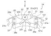
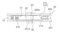
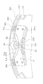
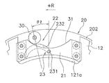
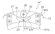
- FIG. 2 is a front view of the hub flange 12 and the torque fluctuation suppressing device 14. Note that FIG. 2 shows one (near side) inertia ring removed. 3 is a view seen from the direction A in FIG. 2, and FIG. 4 is an external perspective view of FIG. 2 and the subsequent drawings show a part of the hub flange 12 and the torque fluctuation suppressing device 14, but as a whole, the portions shown in each figure are provided at equal angular intervals at four locations in the circumferential direction. Yes.
- the torque fluctuation suppressing device 14 includes a first inertia ring 201 and a second inertia ring 202 that constitute the mass body 20, four centrifuges 21, four cam mechanisms 22, four restriction mechanisms 23, have.
- the first and second inertia rings 201 and 202 are plates each having a predetermined thickness formed in a continuous annular shape, and as shown in FIG. 3, both axial sides of the hub flange 12 sandwich the hub flange 12. Are arranged with a predetermined gap. That is, the hub flange 12 and the first and second inertia rings 201 and 202 are arranged side by side in the axial direction.
- the first and second inertia rings 201 and 202 have the same rotation axis as the rotation axis of the hub flange 12, can rotate together with the hub flange 12, and can rotate relative to the hub flange 12.
- first and second inertia rings 201, 202 holes 201a, 202a penetrating in the axial direction are formed. And the 1st inertia ring 201 and the 2nd inertia ring 202 are being fixed by the rivet 24 which penetrates those holes 201a and 202a. Therefore, the first inertia ring 201 cannot move in the axial direction, the radial direction, and the rotation direction with respect to the second inertia ring 202.
- the hub flange 12 is formed in a disc shape, and the inner peripheral portion is connected to the output hub 5 as described above.
- Four protrusions 121 are formed on the outer peripheral portion of the hub flange 12 so as to protrude further to the outer peripheral side and have a predetermined width in the circumferential direction.
- a concave portion 121a having a predetermined width is formed at the central portion of the protruding portion 121 in the circumferential direction.
- the recess 121a is formed so as to open to the outer peripheral side and has a predetermined depth.
- the centrifuge 21 is disposed in the recess 121 a of the hub flange 12 and can move in the radial direction by the centrifugal force generated by the rotation of the hub flange 12.
- the centrifuge 21 is formed to extend in the circumferential direction, and has grooves 21 a and 21 b at both ends in the circumferential direction.
- the widths of the grooves 21a and 21b are larger than the thickness of the hub flange 12, and the hub flange 12 is inserted into a part of the grooves 21a and 21b.
- the outer peripheral surface 21c of the centrifuge 21 is formed in an arc shape that is recessed toward the inner peripheral side, and functions as a cam 31 as described later.
- Two rollers 26a and 26b are disposed in the grooves 21a and 21b at both ends of the centrifuge 21, respectively.
- Each of the rollers 26a and 26b is rotatably mounted around a pin 27 provided through the grooves 21a and 21b in the rotation axis direction. And each roller 26a, 26b can contact
- the cam mechanism 22 includes a cylindrical roller 30 as a cam follower and a cam 31 that is an outer peripheral surface 21 c of the centrifuge 21.
- the roller 30 is fitted on the outer periphery of the trunk portion of the rivet 24. That is, the roller 30 is supported by the rivet 24.
- the roller 30 is preferably mounted so as to be rotatable with respect to the rivet 24, but may not be rotatable.
- the cam 31 is an arcuate surface with which the roller 30 abuts.
- the restriction mechanism 23 allows the centrifuge 21 to be operated by the cam mechanism 22 and restricts the movement of the centrifuge 21 in the radial direction.
- the restriction mechanism 23 includes a pin (restriction shaft) 231 and a groove (restriction groove) 232.
- the pin 231 is provided so as to penetrate the centrifuge 21 in the rotation axis direction. More specifically, the pin 231 is provided at the central portion in the longitudinal direction (circumferential direction) of the centrifuge 21 so as to extend along the rotation axis. Further, the groove 232 is formed in the same shape at the same position in each of the first inertia ring 201 and the second inertia ring 202. The groove 232 is formed in a convex arc shape on the outer peripheral side, and a pin 231 is inserted into the groove 232. A predetermined gap is provided between the pin 231 and the groove 232, and the pin 231 can move smoothly in the groove 232.
- the pin 231 is located at the center in the longitudinal direction (circumferential direction) of the groove 232.
- the centrifuge 21 moves in the radial direction by the operation of the cam mechanism 22.
- the pin 231 moves along the groove 232.
- the shape of the groove 232 is set so that the inner peripheral surface of the centrifuge 21 does not contact the bottom surface of the recess 121 a of the hub flange 12 wherever the pin 231 is located in the groove 232.
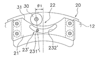
- the hub flange 12 and the inertia ring 20 rotate in the state shown in FIG. In this state, the roller 30 of the cam mechanism 22 abuts on the innermost circumferential position (circumferential center position) of the cam 31 and the rotational phase difference between the hub flange 12 and the inertia ring 20 is “0”. .
- rotational phase difference the relative displacement amount in the rotational direction between the hub flange 12 and the inertia ring 20 is referred to as “rotational phase difference”, which is shown in FIG. 2, FIG. 5 and FIG. 21 shows a deviation between the center position of the circumferential direction of the cam 21 and the cam 31 and the center position of the roller 30.
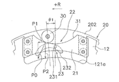
- FIG. 5 shows a case where a rotational phase difference + ⁇ 1 (for example, 5 degrees) is generated on the + R side
- FIG. 6 similarly shows a case where a rotational phase difference + ⁇ 2 (for example, 10 degrees) is generated on the + R side.
- the first component force P1 is a force that moves the hub flange 12 in the left direction in FIG. 5 via the cam mechanism 22 and the centrifuge 21. That is, a force in the direction of reducing the rotational phase difference between the hub flange 12 and the inertia ring 20 acts on the hub flange 12. Moreover, the centrifuge 21 is moved to the inner peripheral side against the centrifugal force by the second component force P2.
- the force that suppresses the torque fluctuation described above varies depending on the centrifugal force, that is, the rotational speed of the hub flange 12, and also varies depending on the rotational phase difference and the shape of the cam 31. Therefore, by setting the shape of the cam 31 as appropriate, the characteristics of the torque fluctuation suppressing device 14 can be optimized according to engine specifications and the like.
- the shape of the cam 31 can be made such that the first component force P1 changes linearly according to the rotational phase difference in the state where the same centrifugal force is acting.
- the shape of the cam 31 can be a shape in which the first component force P1 changes nonlinearly according to the rotational phase difference.
- the movement of the centrifuge 21 is not restricted by the restriction mechanism 23. That is, the pin 231 provided on the centrifuge 21 can move smoothly along the groove 232, and the movement of the centrifuge 21 in the radial direction is not restricted.
- centrifugal force does not act on the centrifuge 21, so that the centrifuge 21 located above the four centrifuges 21 is not It falls in the circumferential direction (downward).
- the restriction mechanism 23 is not provided, the centrifuge 21 falls downward, the inner peripheral surface of the centrifuge 21 collides with the bottom surface of the recess 121a, and a hitting sound is generated.
- the centrifuge 21 located above when the rotation is stopped falls to a position where it contacts the bottom surface of the recess 121a. In this case, there is a relatively wide gap between the cam 31 and the roller 30 that are the outer peripheral surface of the centrifuge 21.
- the centrifuge 21 moves to the outer peripheral side and collides with the roller 30 to generate a hitting sound.
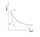
- FIG. 7 is a diagram illustrating an example of torque fluctuation suppression characteristics.
- the horizontal axis represents the rotational speed, and the vertical axis represents the torque fluctuation (rotational speed fluctuation).
- the characteristic Q1 is a case where a device for suppressing torque fluctuation is not provided
- the characteristic Q2 is a case where a conventional dynamic damper device is provided
- the characteristic Q3 is a case where the torque fluctuation suppressing device 14 of the present embodiment is provided. Show.
- Embodiment- 8 to 10 show a part of the torque fluctuation suppressing device according to the second embodiment of the present invention, and are equivalent to FIGS. 2, 5 and 6 of the first embodiment.
- the inertia ring 201 on one side is removed.
- the basic configuration of the torque fluctuation suppressing device 14 ′ of the second embodiment such as the operation of the cam mechanism 22 is the same as that of the first embodiment, but the configuration of the restriction mechanism is different from that of the first embodiment.
- the restriction mechanism 23 ' shown in FIG. 8 permits the operation of the centrifuge 21' by the cam mechanism 22 and restricts the movement of the centrifuge 21 'in the radial direction, as in the first embodiment.
- the regulation mechanism 23 ' has a pin (regulation shaft) 231' and a groove (regulation groove) 232 '.
- the pin 231 ′ is provided so as to connect the first inertia ring 201 and the second inertia ring 202. In other words, the pin 231 ′ extends between the inertia rings 201 and 202 along the rotation axis direction. Further, the pin 231 ′ is provided so as to be located at the center in the circumferential direction of the recess 121a of the hub flange 12 in a state where there is no rotational phase difference between the hub flange 12 and the inertia ring 20 (the state shown in FIG. 8). ing.
- the groove 232 ′ is formed in an arc shape convex toward the inner peripheral side at the center in the circumferential direction of the centrifuge 21 ′, and the pin 231 ′ passes through the groove 232 ′.
- a predetermined gap is provided between the pin 231 ′ and the groove 232 ′, and the pin 231 ′ can move smoothly in the groove 232 ′.
- the shape of the groove 232 ′ is set so that the inner peripheral surface of the centrifuge 21 ′ does not come into contact with the bottom surface of the recess 121 a of the hub flange 12 no matter where the pin 231 ′ is located in the groove 232 ′.
- FIGS. 9 and 10 are diagrams showing the operating state of the cam mechanism 22 and correspond to FIGS. 5 and 6 of the first embodiment. Since the operation of the cam mechanism 22 and the operation of the restriction mechanism 23 'are the same as those in the first embodiment, detailed description thereof is omitted.
- FIG. 11 shows a part of the torque fluctuation suppressing device according to the third embodiment, and corresponds to FIG. 2 of the first embodiment and FIG. 8 of the second embodiment.
- the restriction mechanism 23 ′′ of the third embodiment is composed of a pin 231 ′ and a restriction surface 232 ′′ formed on the inner peripheral surface of the centrifuge 21 ′′.
- the pin 231 ′ is the same as in the second embodiment.
- the regulating surface 232 ′′ is the inner peripheral surface of the centrifuge 21 ′′, and this regulating surface 232 ′′ is in contact with the pin 231 ′.
- the restricting surface 232 ′′ is formed in an arc shape that is convex on the inner peripheral side.
- the inner peripheral surface of the centrifuge 21 ′ contacts the bottom surface of the recess 121 a of the hub flange 12 no matter where the pin 231 ′ is in contact with the regulating surface 232 ′′.
- the shape of the restricting surface 232 ′′ is set so as not to occur.
- FIG. 12 shows a part of the torque fluctuation suppressing device according to the fourth embodiment, and corresponds to FIG. 2 of the first embodiment.
- this 4th Embodiment only the structure of a control mechanism differs from 1st Embodiment. That is, in the fourth embodiment, the elastic body 233 is provided on the outer peripheral surface of the pin 321.
- the elastic body 233 may be provided not on the outer peripheral surface of the pin 231 but on the inner peripheral surface of the restriction groove 232, that is, the surface with which the pin 231 contacts.
- FIG. 13 shows a part of the torque fluctuation suppressing device according to the fifth embodiment, which corresponds to FIG. 2 of the first embodiment.
- the restriction mechanism 23 ′ ′′ of the fifth embodiment includes a pin (regulation shaft) 27 ′ that supports the rollers 26a and 26b and grooves (regulation grooves) formed in the first and second inertia rings 201 and 202. 232 ′ ′′.
- the pin 27 ′ is provided through the centrifuge 21 and the groove 232 ′′ ′′ of the first and second inertia rings 201, 202 in the rotation axis direction.
- the groove 232 ′′ ′′ is formed in the same position and in the same shape in each of the first inertia ring 201 and the second inertia ring 202.
- the groove 232 ′′ ′′ is formed in a convex arc shape on the outer peripheral side, and a pin 27 ′ is inserted into the groove 232 ′′ ′′.
- a predetermined gap is provided between the pin 27 ′ and the groove 232 ′′ ′′, and the pin 27 ′ can move smoothly in the groove 232 ′′ ′′.
- the inertia ring is constituted by a continuous annular member, but a plurality of divided inertia bodies may be arranged in the circumferential direction.
- a holding member such as an annular holding ring on the outer peripheral side of the inertia body.
- the guide roller is disposed as the guide portion, but another member that reduces friction such as a resin race or a sheet may be disposed.
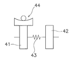
- FIG. 14 is a diagram schematically showing the torque converter, and the torque converter is provided between the input side rotating body 41, the hub flange 42, and the input side rotating body 41 and the hub flange 42. And a damper 43.
- the input side rotating body 41 includes members such as a front cover, a drive plate, and a piston.
- the hub flange 42 includes a driven plate and a turbine hub.
- the damper 43 includes a plurality of torsion springs.
- a centrifuge is provided in any of the rotating members that constitute the input-side rotator 41, and a cam mechanism and a regulating mechanism that operate using centrifugal force acting on the centrifuge. 44 is provided.
- the cam mechanism and the regulating mechanism 44 the same configuration as that shown in each of the above embodiments can be applied.
- a centrifuge is provided in any of the rotating members constituting the hub flange 42, and a cam mechanism and a regulation that operate using centrifugal force acting on the centrifuge A mechanism 44 is provided.
- the cam mechanism and the regulating mechanism 44 the same configuration as that shown in each of the above embodiments can be applied.
- the torque converter shown in FIG. 16 has another damper 45 and an intermediate member 46 provided between the two dampers 43, 45 in addition to the configuration shown in FIGS. is doing.
- the intermediate member 46 is rotatable relative to the input side rotating body 41 and the hub flange 42, and causes the two dampers 43 and 45 to act in series.
- the intermediate member 46 is provided with a centrifuge, and a cam mechanism and a regulating mechanism 44 that operate by utilizing a centrifugal force acting on the centrifuge are provided.
- a cam mechanism and a regulating mechanism 44 that operate by utilizing a centrifugal force acting on the centrifuge are provided.
- the torque converter shown in FIG. 17 has a float member 47.
- the float member 47 is a member for supporting the torsion spring constituting the damper 43, and is formed, for example, in an annular shape so as to cover the outer periphery and at least one side surface of the torsion spring. Further, the float member 47 is rotatable relative to the input side rotating body 41 and the hub flange 42, and rotates around the damper 43 by friction with the torsion spring of the damper 43. That is, the float member 47 also rotates.
- the float member 47 is provided with a centrifuge 48, and a cam mechanism and a regulation mechanism 44 that operate using a centrifugal force acting on the centrifuge 48 are provided.
- a cam mechanism and a regulation mechanism 44 that operate using a centrifugal force acting on the centrifuge 48 are provided.
- FIG. 18 is a schematic diagram of a power transmission device having a flywheel 50 having two inertia bodies 51 and 52 and a clutch device 54. That is, the flywheel 50 disposed between the engine and the clutch device 54 includes a first inertial body 51, a second inertial body 52 disposed so as to be rotatable relative to the first inertial body 51, and two inertial bodies. And a damper 53 disposed between 51 and 52. The second inertia body 52 also includes a clutch cover that constitutes the clutch device 54.
- a centrifuge is provided in any of the rotating members constituting the second inertial body 52, and a cam mechanism and a regulating mechanism 55 that operate using centrifugal force acting on the centrifuge. Is provided.
- the cam mechanism and the restriction mechanism 55 the same configuration as that shown in each of the above embodiments can be applied.
- FIG. 19 is an example in which a centrifuge is provided in the first inertial body 51 in the same power transmission device as in FIG.
- a cam mechanism and a regulation mechanism 55 that operate using the centrifugal force acting on the centrifuge are provided.
- the cam mechanism and the restriction mechanism 55 the same configuration as that shown in each of the above embodiments can be applied.
- the power transmission device shown in FIG. 20 includes another damper 56 and an intermediate member 57 provided between the two dampers 53, 56. Have.
- the intermediate member 57 is rotatable relative to the first inertial body 51 and the second inertial body 52.
- a centrifuge 58 is provided on the intermediate member 57, and a cam mechanism and a regulation mechanism 55 that operate using a centrifugal force acting on the centrifuge 58 are provided.
- the cam mechanism and the restriction mechanism 55 the same configuration as that shown in each of the above embodiments can be applied.
- FIG. 21 is a schematic diagram of a power transmission device in which a clutch device is provided on one flywheel.
- the first inertia body 61 in FIG. 21 includes one flywheel and a clutch cover of the clutch device 62.
- a centrifuge is provided in one of the rotating members constituting the first inertial body 61, and a cam mechanism and a regulating mechanism 64 that operate using a centrifugal force acting on the centrifuge are provided. Yes.
- the cam mechanism and the regulating mechanism 64 the same configuration as that shown in each of the above embodiments can be applied.
- FIG. 22 is an example in which a centrifuge 65 is provided on the output side of the clutch device 62 in the power transmission device similar to FIG.
- a cam mechanism and a regulation mechanism 64 that operate using centrifugal force acting on the centrifuge 65 are provided.
- the cam mechanism and the regulating mechanism 64 the same configuration as that shown in each of the above embodiments can be applied.
- the torque fluctuation suppressing device of the present invention may be disposed on any of the rotating members constituting the transmission, and further, the shaft (propeller shaft or drive) on the output side of the transmission (Shaft).
- the torque fluctuation suppressing device of the present invention may be further applied to a conventionally known dynamic damper device or a power transmission device provided with a pendulum type damper device.
- the peak of the torque fluctuation can be suppressed in a relatively wide rotational speed range. Further, in the present invention, it is possible to suppress the hitting sound that the centrifuge collides with other members.
- 1 Torque Converter 11 Input Side Rotating Body 12, 120 Hub Flange (Rotating Body) 121a Opening 14, 14 'Torque fluctuation suppressing device 20, 201, 202 Inertia ring (mass body) 21, 21 ′, 21 ′′ Centrifuge 22, 22 Cam mechanism 23, 23 ′, 23 ′′, 23 ′′ Restricting mechanism 231, 231 ′ Pin (regulating shaft) 232, 232 ', 232''' groove (regulating groove) 232 '' restriction surface 30 roller (cam follower) 31 cams
Abstract
比較的広い回転数域においてトルク変動のピークを抑える。この装置は、イナーシャリング(20)と、複数の遠心子(21)と、複数のカム機構(22)と、複数の規制機構(23)と、を備えている。イナーシャリング(20)は、ハブフランジ(12)とともに回転可能であり、かつハブフランジ(12)に対して相対回転自在に配置されている。遠心子(21)は、ハブフランジ(12)及びイナーシャリング(20)の回転による遠心力を受けるように配置されている。カム機構(22)は、遠心子(21)に作用する遠心力を受けて、ハブフランジ(12)とイナーシャリング(20)との間に回転方向における相対変位が生じたときには、遠心力を、相対変位が小さくなる方向の円周方向力に変換する。規制機構(23)は、カム機構(22)による遠心子(21)の作動を許容し、かつ遠心子(21)の径方向の移動を規制する。
Description
本発明は、トルク変動抑制装置、特に、回転軸の回りに回転するとともにトルクが入力される回転体のトルク変動を抑制するためのトルク変動抑制装置に関する。また、本発明は、トルク変動抑制装置を備えたトルクコンバータ及び動力伝達装置に関する。
例えば、自動車のエンジンとトランスミッションとの間には、ダンパ装置を含むクラッチ装置やトルクコンバータが設けられている。また、トルクコンバータには、燃費低減のために、所定の回転数以上で機械的にトルクを伝達するためのロックアップ装置が設けられている。
ロックアップ装置は、一般に、クラッチ部と、複数のトーションスプリングを有するダンパと、を有している。また、クラッチ部は、油圧の作用によってフロントカバーに押し付けられる摩擦部材付きのピストンを有している。そして、ロックアップオンの状態では、トルクは、フロントカバーから摩擦部材を介してピストンに伝達され、さらに複数のトーションスプリングを介して出力側の部材に伝達される。
このようなロックアップ装置では、複数のトーションスプリングを有するダンパによって、トルク変動(回転速度変動)が抑えられる。
また、特許文献1のロックアップ装置では、イナーシャ部材を含むダイナミックダンパ装置を設けることによって、トルク変動を抑えるようにしている。特許文献1のダイナミックダンパ装置は、トーションスプリングを支持するプレートに装着されており、このプレートと相対回転自在な1対のイナーシャリングと、プレートとイナーシャリングとの間に設けられた複数のコイルスプリングと、を有している。
特許文献1を含む従来のダイナミックダンパ装置では、所定の回転数域に現れるトルク変動のピークを抑えることができる。しかし、エンジンの仕様等が変わると、それに応じてトルク変動のピークが現れる回転数域が変わる。このため、エンジンの仕様等の変更に伴ってイナーシャリングの慣性量及びコイルスプリングのばね定数を変更する必要があり、対応が困難な場合がある。
本発明の課題は、回転部材のトルク変動を抑えるための装置において、比較的広い回転数域においてトルク変動のピークを抑えることができるようにすることにある。
(1)本発明に係るトルク変動抑制装置は、トルクが入力される回転体のトルク変動を抑制する装置である。このトルク変動抑制装置は、質量体と、複数の遠心子と、複数のカム機構と、複数の規制機構と、を備えている。質量体は、回転体とともに回転可能であり、かつ回転体に対して相対回転自在に配置されている。複数の遠心子は、回転体及び質量体の回転による遠心力を受けるように配置されている。複数のカム機構は、遠心子に作用する遠心力を受けて、回転体と質量体との間に回転方向における相対変位が生じたときには、遠心力を、相対変位が小さくなる方向の円周方向力に変換する。複数の規制機構は、カム機構による遠心子の作動を許容し、かつ遠心子の径方向の移動を規制する。
この装置では、回転体にトルクが入力されると、回転体及び質量体が回転する。回転体に入力されるトルクに変動がない場合は、回転体と質量体との間の回転方向における相対変位はなく、同期して回転する。一方、入力されるトルクに変動がある場合は、質量体は回転体に対して相対回転自在に配置されているために、トルク変動の程度によっては、両者の間に回転方向における相対変位(以下、この変位を「回転位相差」と表現する場合がある)が生じる。
ここで、回転体及び質量体が回転すると、遠心子は遠心力を受ける。そして、回転体と質量体との間に相対変位が生じたときには、カム機構は遠心子に作用する遠心力を円周方向力に変換し、この円周方向力は回転体と質量体の間の相対変位を小さくするように作用する。このようなカム機構の作動によって、トルク変動が抑えられる。
ここでは、遠心子に作用する遠心力を、トルク変動を抑えるための力として利用しているので、回転体の回転数に応じてトルク変動を抑制する特性が変わることになる。また、例えばカムの形状等によって、トルク変動を抑制する特性を適切に設定することができ、より広い回転数域におけるトルク変動のピークを抑えることができる。
また、ここでは、規制機構によって、カム機構による遠心子の作動は許容されるが、遠心子の径方向の移動が規制される。このため、遠心子が径方向に移動して回転体等の他の部材と衝突し、打音が発生するのを避けることができる。また、遠心子と他の部材とが衝突する場合であっても、衝突時の打音を抑えることができる。
(2)好ましくは、規制機構は、規制軸と規制溝とを有する。規制軸は、質量体及び遠心子の一方に設けられ、回転体の回転軸に沿って延びる。規制溝は、質量体及び遠心子の他方に形成され、規制軸が挿入されている。
ここでは、例えば遠心子に規制軸が設けられ、この規制軸は例えば質量体に形成された規制溝に挿入されている。このため、遠心子の作動時には、規制軸が規制溝に規制されて移動し、結果的に遠心子の径方向の移動が規制される。
このため、簡単な構成で規制機構を実現できる。また、規制軸が規制溝に挿入されているため、遠心子の径方向の外側及び内側への移動を規制することができる。
(3)好ましくは、別の規制機構は、それぞれ別の規制軸と規制面とを有する。規制軸は、質量体に設けられ、回転体の回転軸に沿って延びる。規制面は、遠心子の内周面に形成され、規制軸が摺動する。
ここでは、遠心子は、内周面に形成された規制面が質量体に設けられた規制軸に当接しながら作動する。このため、遠心子の径方向内方への移動を規制することができる。また、規制軸を案内するための溝を形成する必要がなく、構成がより簡単になる。
(4)好ましくは、規制軸の外周面又は規制軸が当接する面に設けられた弾性体をさらに備えている。
この場合は、規制軸と規制軸が衝突する部分との衝突が緩和され、衝突時の打音をさらに抑えることができる。
(5)好ましくは、回転体は、外周面に複数の凹部を有し、複数の遠心子のそれぞれは回転体の凹部に収容されている。そして、規制機構は、遠心子の内周面が凹部の底面に当接するのを規制する。
この場合は、規制軸と規制軸が衝突する部分との衝突が緩和され、衝突時の打音をさらに抑えることができる。
(5)好ましくは、回転体は、外周面に複数の凹部を有し、複数の遠心子のそれぞれは回転体の凹部に収容されている。そして、規制機構は、遠心子の内周面が凹部の底面に当接するのを規制する。
ここで、回転体及び質量体が回転しているときには、遠心子は遠心力を受けて径方向外方に移動しようとする。一方、回転体及び質量体の回転が停止したときには、遠心子には遠心力が作用しなくなる。したがって、規制機構が設けられていない場合には、複数の遠心子のうちの上方に位置していた遠心子は下方に落下し、凹部の底面に衝突する。この衝突時に打音が発生することになる。
しかし、ここでは、規制機構によって遠心子の径方向の移動が規制され、遠心子が凹部の底面に衝突するのを防止している。したがって、回転停止時に遠心子と凹部の底面との打音をなくすことができる。
(6)好ましくは、カム機構は、質量体及び遠心子の一方に設けられたカムと、質量体及び遠心子の他方に設けられカムに沿って移動するカムフォロアと、を有する。
ここでは、回転体のトルク変動の大きさによって、回転体と質量体との間の回転方向の相対変位量が変動する。このとき、遠心力から変換された円周方向力が、相対変位量に応じて変化するようにカムの形状を設定することにより、トルク変動をより効率的に抑えることができる。
(7)好ましくは、質量体は、回転体を挟んで対向して配置された第1イナーシャリング及び第2イナーシャリングと、第1イナーシャリングと第2イナーシャリングとを相対回転不能に連結するピンと、を有している。遠心子は、回転体の外周部でかつピンの内周側において第1イナーシャリングと第2イナーシャリングとの軸方向間に配置されている。カムフォロアは、内部にピンが軸方向に貫通する孔を有する円筒状のコロである。カムは、遠心子に形成されてカムフォロアに当接し、回転体と質量体との間の回転方向における相対変位量に応じて円周方向力が変化するような形状を有する。
ここでは、第1イナーシャリングと第2イナーシャリングとを連結するピンを利用して、カムフォロアを装着している。このため、カム機構の構成が簡単になる。
(8)本発明に係るトルクコンバータは、エンジンとトランスミッションとの間に配置される。このトルクコンバータは、エンジンからのトルクが入力される入力側回転体と、トランスミッションにトルクを出力するハブフランジと、入力側回転体とタービンとの間に配置されたダンパと、以上に記載のいずれかのトルク変動抑制装置と、を備えている。
(9)本発明に係る動力伝達装置は、フライホイールと、クラッチ装置と、以上に記載のいずれかのトルク変動抑制装置と、を備えている。フライホイールは、回転軸を中心に回転する第1慣性体と、回転軸を中心に回転し第1慣性体と相対回転自在な第2慣性体と、第1慣性体と第2慣性体との間に配置されたダンパと、を有する。クラッチ装置は、フライホイールの第2慣性体に設けられている。
以上のような本発明では、回転部材のトルク変動を抑えるための装置において、比較的広い回転数域においてトルク変動のピークを抑えることができる。また、本発明では、遠心子が他の部材と衝突する打音を抑えることができる。
-第1実施形態-
図1は、本発明の第1実施形態によるトルク変動抑制装置をトルクコンバータのロックアップ装置に装着した場合の模式図である。図1において、O-Oがトルクコンバータの回転軸線である。
図1は、本発明の第1実施形態によるトルク変動抑制装置をトルクコンバータのロックアップ装置に装着した場合の模式図である。図1において、O-Oがトルクコンバータの回転軸線である。
[全体構成]
トルクコンバータ1は、フロントカバー2と、トルクコンバータ本体3と、ロックアップ装置4と、出力ハブ5と、を有している。フロントカバー2にはエンジンからトルクが入力される。トルクコンバータ本体3は、フロントカバー2に連結されたインペラ7と、タービン8と、ステータ(図示せず)と、を有している。タービン8は出力ハブ5に連結されており、出力ハブ5の内周部には、トランスミッションの入力軸(図示せず)がスプラインによって係合可能である。
トルクコンバータ1は、フロントカバー2と、トルクコンバータ本体3と、ロックアップ装置4と、出力ハブ5と、を有している。フロントカバー2にはエンジンからトルクが入力される。トルクコンバータ本体3は、フロントカバー2に連結されたインペラ7と、タービン8と、ステータ(図示せず)と、を有している。タービン8は出力ハブ5に連結されており、出力ハブ5の内周部には、トランスミッションの入力軸(図示せず)がスプラインによって係合可能である。
[ロックアップ装置4]
ロックアップ装置4は、クラッチ部や、油圧によって作動するピストン等を有し、ロックアップオン状態と、ロックアップオフ状態と、を取り得る。ロックアップオン状態では、フロントカバー2に入力されたトルクは、トルクコンバータ本体3を介さずに、ロックアップ装置4を介して出力ハブ5に伝達される。一方、ロックアップオフ状態では、フロントカバー2に入力されたトルクは、トルクコンバータ本体3を介して出力ハブ5に伝達される。
ロックアップ装置4は、クラッチ部や、油圧によって作動するピストン等を有し、ロックアップオン状態と、ロックアップオフ状態と、を取り得る。ロックアップオン状態では、フロントカバー2に入力されたトルクは、トルクコンバータ本体3を介さずに、ロックアップ装置4を介して出力ハブ5に伝達される。一方、ロックアップオフ状態では、フロントカバー2に入力されたトルクは、トルクコンバータ本体3を介して出力ハブ5に伝達される。
ロックアップ装置4は、入力側回転体11と、ハブフランジ12(回転体)と、ダンパ13と、トルク変動抑制装置14と、を有している。
入力側回転体11は、軸方向に移動自在なピストンを含み、フロントカバー2側の側面に摩擦部材16が固定されている。この摩擦部材16がフロントカバー2に押し付けられることによって、フロントカバー2から入力側回転体11にトルクが伝達される。
ハブフランジ12は、入力側回転体11と軸方向に対向して配置され、入力側回転体11と相対回転自在である。ハブフランジ12は出力ハブ5に連結されている。
ダンパ13は、入力側回転体11とハブフランジ12との間に配置されている。ダンパ13は、複数のトーションスプリングを有しており、入力側回転体11とハブフランジ12とを回転方向に弾性的に連結している。このダンパ13によって、入力側回転体11からハブフランジ12にトルクが伝達されるとともに、トルク変動が吸収、減衰される。
[トルク変動抑制装置14]
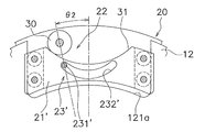
図2は、ハブフランジ12及びトルク変動抑制装置14の正面図である。なお、図2は一方(手前側)のイナーシャリングを取り外して示している。図3は図2のA方向から視た図、図4は図2の外観斜視図である。図2以降の図ではハブフランジ12及びトルク変動抑制装置14の一部を示しているが、全体としては、円周方向の4ヶ所に、各図に示した部分が等角度間隔で設けられている。
図2は、ハブフランジ12及びトルク変動抑制装置14の正面図である。なお、図2は一方(手前側)のイナーシャリングを取り外して示している。図3は図2のA方向から視た図、図4は図2の外観斜視図である。図2以降の図ではハブフランジ12及びトルク変動抑制装置14の一部を示しているが、全体としては、円周方向の4ヶ所に、各図に示した部分が等角度間隔で設けられている。
トルク変動抑制装置14は、質量体20を構成する第1イナーシャリング201及び第2イナーシャリング202と、4個の遠心子21と、4個のカム機構22と、4個の規制機構23と、を有している。
<第1及び第2イナーシャリング201,202>
第1及び第2イナーシャリング201,202は、それぞれ連続した円環状に形成された所定の厚みを有するプレートであり、図3に示すように、ハブフランジ12を挟んでハブフランジ12の軸方向両側に所定の隙間をあけて配置されている。すなわち、ハブフランジ12と第1及び第2イナーシャリング201,202とは、軸方向に並べて配置されている。第1及び第2イナーシャリング201,202は、ハブフランジ12の回転軸と同じ回転軸を有し、ハブフランジ12とともに回転可能で、かつハブフランジ12に対して相対回転自在である。
第1及び第2イナーシャリング201,202は、それぞれ連続した円環状に形成された所定の厚みを有するプレートであり、図3に示すように、ハブフランジ12を挟んでハブフランジ12の軸方向両側に所定の隙間をあけて配置されている。すなわち、ハブフランジ12と第1及び第2イナーシャリング201,202とは、軸方向に並べて配置されている。第1及び第2イナーシャリング201,202は、ハブフランジ12の回転軸と同じ回転軸を有し、ハブフランジ12とともに回転可能で、かつハブフランジ12に対して相対回転自在である。
第1及び第2イナーシャリング201,202には軸方向に貫通する孔201a,202aが形成されている。そして、第1イナーシャリング201と第2イナーシャリング202とは、それらの孔201a,202aを貫通するリベット24によって固定されている。したがって、第1イナーシャリング201は、第2イナーシャリング202に対して、軸方向、径方向、及び回転方向に移動不能である。
<ハブフランジ12>
ハブフランジ12は、円板状に形成され、内周部が前述のように出力ハブ5に連結されている。ハブフランジ12の外周部には、外周側にさらに突出し、円周方向に所定の幅を有する4つの突起部121が形成されている。突起部121の円周方向の中央部には、所定の幅の凹部121aが形成されている。凹部121aは、外周側に開くように形成され、所定の深さを有している。
ハブフランジ12は、円板状に形成され、内周部が前述のように出力ハブ5に連結されている。ハブフランジ12の外周部には、外周側にさらに突出し、円周方向に所定の幅を有する4つの突起部121が形成されている。突起部121の円周方向の中央部には、所定の幅の凹部121aが形成されている。凹部121aは、外周側に開くように形成され、所定の深さを有している。
<遠心子21>
遠心子21は、ハブフランジ12の凹部121aに配置されており、ハブフランジ12の回転による遠心力によって径方向に移動可能である。遠心子21は、円周方向に延びて形成され、円周方向の両端に溝21a,21bを有している。溝21a,21bの幅は、ハブフランジ12の厚みより大きく、溝21a,21bの一部にハブフランジ12が挿入されている。
遠心子21は、ハブフランジ12の凹部121aに配置されており、ハブフランジ12の回転による遠心力によって径方向に移動可能である。遠心子21は、円周方向に延びて形成され、円周方向の両端に溝21a,21bを有している。溝21a,21bの幅は、ハブフランジ12の厚みより大きく、溝21a,21bの一部にハブフランジ12が挿入されている。
なお、遠心子21の外周面21cは、内周側に窪む円弧状に形成されており、後述するように、カム31として機能する。
遠心子21の両端の溝21a,21bには、それぞれ2個のローラ26a,26bが配置されている。各ローラ26a,26bは、溝21a,21bを回転軸方向に貫通して設けられたピン27の回りに回転自在に装着されている。そして、各ローラ26a,26bは、凹部121aの側面に当接して転動可能である。
<カム機構22>
カム機構22は、カムフォロアとしての円筒状のコロ30と、遠心子21の外周面21cであるカム31と、から構成されている。コロ30は、リベット24の胴部の外周に嵌めこまれている。すなわち、コロ30はリベット24に支持されている。なお、コロ30は、リベット24に対して回転自在に装着されているのが好ましいが、回転不能であってもよい。カム31は、コロ30が当接する円弧状の面であり、ハブフランジ12と第1及び第2イナーシャリング201,202とが所定の角度範囲で相対回転した際には、コロ30はこのカム31に沿って移動する。
カム機構22は、カムフォロアとしての円筒状のコロ30と、遠心子21の外周面21cであるカム31と、から構成されている。コロ30は、リベット24の胴部の外周に嵌めこまれている。すなわち、コロ30はリベット24に支持されている。なお、コロ30は、リベット24に対して回転自在に装着されているのが好ましいが、回転不能であってもよい。カム31は、コロ30が当接する円弧状の面であり、ハブフランジ12と第1及び第2イナーシャリング201,202とが所定の角度範囲で相対回転した際には、コロ30はこのカム31に沿って移動する。
詳細は後述するが、コロ30とカム31との接触によって、ハブフランジ12と第1及び第2イナーシャリング201,202との間に回転位相差が生じたときに、遠心子21に生じた遠心力は、回転位相差が小さくなるような円周方向の力に変換される。
<規制機構23>
規制機構23は、カム機構22による遠心子21の作動を許容し、かつ遠心子21の径方向の移動を規制する。規制機構23は、ピン(規制軸)231と、溝(規制溝)232と、を有している。
規制機構23は、カム機構22による遠心子21の作動を許容し、かつ遠心子21の径方向の移動を規制する。規制機構23は、ピン(規制軸)231と、溝(規制溝)232と、を有している。
ピン231は、遠心子21を回転軸方向に貫通して設けられている。より詳細には、ピン231は、遠心子21の長手方向(円周方向)の中央部に、回転軸に沿って延びるように設けられている。また、溝232は、第1イナーシャリング201及び第2イナーシャリング202のそれぞれに、同じ位置に同じ形状で形成されている。溝232は、外周側に凸の円弧状に形成され、この溝232にピン231が挿入されている。ピン231と溝232との間には所定の隙間が設けられており、ピン231は溝232内をスムーズに移動することが可能である。
また、ハブフランジ12と第1及び第2イナーシャリング201,202とが同期して回転しているとき(すなわちハブフランジ12と両イナーシャリング201,202との間に回転位相差がないとき)は、図2に示すように、ピン231は溝232の長手方向(円周方向)の中央に位置している。そして、ハブフランジ12と両イナーシャリング201,202との間に回転位相差が生じた場合は、カム機構22の作動によって遠心子21は径方向に移動する。この遠心子21の作動に伴って、ピン231は溝232に沿って移動する。しかし、ピン231が溝232のどこに位置しても、遠心子21の内周面がハブフランジ12の凹部121aの底面に当接しないように溝232の形状が設定されている。
[カム機構22の作動]
図2、図5及び図6を用いて、カム機構22の作動(トルク変動の抑制)について説明する。なお、以下の説明では、第1及び第2イナーシャリング201,202を、単に「イナーシャリング20」と記す場合もある。
図2、図5及び図6を用いて、カム機構22の作動(トルク変動の抑制)について説明する。なお、以下の説明では、第1及び第2イナーシャリング201,202を、単に「イナーシャリング20」と記す場合もある。
ロックアップオン時には、フロントカバー2に伝達されたトルクは、入力側回転体11及びダンパ13を介してハブフランジ12に伝達される。
トルク伝達時にトルク変動がない場合は、図2に示すような状態で、ハブフランジ12及びイナーシャリング20は回転する。この状態では、カム機構22のコロ30はカム31のもっとも内周側の位置(円周方向の中央位置)に当接し、ハブフランジ12とイナーシャリング20との回転位相差は「0」である。
前述のように、ハブフランジ12とイナーシャリング20との間の回転方向の相対変位量を、「回転位相差」と称しているが、これらは、図2、図5及び図6では、遠心子21及びカム31の円周方向の中央位置と、コロ30の中心位置と、のずれを示すものである。
ここで、トルクの伝達時にトルク変動が存在すると、図5及び図6に示すように、ハブフランジ12とイナーシャリング20との間には、回転位相差θが生じる。図5は+R側に回転位相差+θ1(例えば5度)が生じた場合を示し、図6は同様に+R側に回転位相差+θ2(例えば10度)が生じた場合を示している。
図5に示すように、ハブフランジ12とイナーシャリング20との間に回転位相差+θ1が生じた場合は、カム機構22のコロ30は、カム31に沿って相対的に図5における左側に移動する。このとき、遠心子21には遠心力が作用しているので、遠心子21に形成されたカム31がコロ30から受ける反力は、図5のP0の方向及び大きさとなる。この反力P0によって、円周方向の第1分力P1と、遠心子21を内周側に向かって移動させる方向の第2分力P2と、が発生する。
そして、第1分力P1は、カム機構22及び遠心子21を介してハブフランジ12を図5における左方向に移動させる力となる。すなわち、ハブフランジ12とイナーシャリング20との回転位相差を小さくする方向の力が、ハブフランジ12に作用することになる。また、第2分力P2によって、遠心子21は、遠心力に抗して内周側に移動させられる。
なお、逆方向に回転位相差が生じた場合は、コロ30がカム31に沿って相対的に図5の右側に移動するが、作動原理は同じである。
以上のように、トルク変動によってハブフランジ12とイナーシャリング20との間に回転位相差が生じると、遠心子21に作用する遠心力及びカム機構22の作用によって、ハブフランジ12は、両者の回転位相差を小さくする方向の力(第1分力P1)を受ける。この力によって、トルク変動が抑制される。
以上のトルク変動を抑制する力は、遠心力、すなわちハブフランジ12の回転数によって変化するし、回転位相差及びカム31の形状によっても変化する。したがって、カム31の形状を適宜設定することによって、トルク変動抑制装置14の特性を、エンジン仕様等に応じた最適な特性にすることができる。
例えば、カム31の形状は、同じ遠心力が作用している状態で、回転位相差に応じて第1分力P1が線形に変化するような形状にすることができる。また、カム31の形状は、回転位相差に応じて第1分力P1が非線形に変化する形状にすることができる。
なお、以上のようなカム機構22の作動中においては、遠心子21は規制機構23によって移動を規制されない。すなわち、遠心子21に設けられたピン231は溝232に沿ってスムーズに移動することが可能であり、遠心子21の径方向の移動が規制されることはない。
一方、ハブフランジ12及びイナーシャリング20の回転が停止する際と、ハブフランジ12及びイナーシャリング20が回転を開始した直後に、遠心子21は規制機構23によって径方向の移動が規制される。
具体的には、ハブフランジ12及びイナーシャリング20が回転を停止すると、遠心子21には遠心力が作用しなくなるので、4つの遠心子21のうちの上方に位置している遠心子21は内周方向(下方)に落下する。このとき、仮に規制機構23が設けられていないとすれば、遠心子21が下方に落下し、遠心子21の内周面が凹部121aの底面に衝突し、打音が発生することになる。
しかし、ここでは規制機構23が設けられているので、図6に示すように、遠心子21に固定されたピン231が溝232の端面に当接し、遠心子21は図6に示す位置からさらに内周側(下方)へ移動するのが規制される。このため、遠心子21の内周面が凹部121aの底面に衝突することはなく、回転停止時の打音を避けることができる。
また、仮に規制機構23が設けられていないとすれば、回転停止時には上方に位置する遠心子21は凹部121aの底面に当接する位置まで落下していることになる。この場合は、遠心子21の外周面であるカム31とコロ30との間には比較的広い隙間が存在する。この状態でハブフランジ12及びイナーシャリング20が回転し始めると、遠心子21は外周側に移動してコロ30と衝突し、打音が発生することになる。
しかし、ここでは規制機構23が設けられているので、図6に示すように、回転が停止して遠心子21がもっとも内周側(下方)に落下しているときにも、遠心子21の外周面とコロ30とは当接するか、あるいは微小な隙間しかない。したがって、この状態から回転が開始されて遠心子21が外周側に移動しても、打音がしないか、あるいは発生したとしても打音を抑えることができる。
[特性の例]
図7は、トルク変動抑制特性の一例を示す図である。横軸は回転数、縦軸はトルク変動(回転速度変動)である。特性Q1はトルク変動を抑制するための装置が設けられていない場合、特性Q2は従来のダイナミックダンパ装置が設けられた場合、特性Q3は本実施形態のトルク変動抑制装置14が設けられた場合を示している。
図7は、トルク変動抑制特性の一例を示す図である。横軸は回転数、縦軸はトルク変動(回転速度変動)である。特性Q1はトルク変動を抑制するための装置が設けられていない場合、特性Q2は従来のダイナミックダンパ装置が設けられた場合、特性Q3は本実施形態のトルク変動抑制装置14が設けられた場合を示している。
この図7から明らかなように、従来のダイナミックダンパ装置が設けられた装置(特性Q2)では、特定の回転数域のみについてトルク変動を抑制することができる。一方、本実施形態(特性Q3)では、すべての回転数域においてトルク変動を抑制することができる。
-第2実施形態-
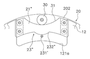
図8~図10は本発明の第2実施形態によるトルク変動抑制装置の一部を示しており、第1実施形態の図2、図5及び図6に相当する図である。なお、これらの図は、一方(各図における手前側)のイナーシャリング201を取り外して示している。
図8~図10は本発明の第2実施形態によるトルク変動抑制装置の一部を示しており、第1実施形態の図2、図5及び図6に相当する図である。なお、これらの図は、一方(各図における手前側)のイナーシャリング201を取り外して示している。
第2実施形態のトルク変動抑制装置14’は、カム機構22の作動等の基本的な構成は第1実施形態と同様であるが、規制機構の構成が第1実施形態と異なっている。
図8に示す規制機構23’は、第1実施形態と同様に、カム機構22による遠心子21’の作動を許容し、かつ遠心子21’の径方向の移動を規制する。規制機構23’は、ピン(規制軸)231’と、溝(規制溝)232’と、を有している。
ピン231’は、第1イナーシャリング201と第2イナーシャリング202とを連結するように設けられている。すなわち、ピン231’は回転軸方向に沿って両イナーシャリング201,202間に延びている。また、ピン231’は、ハブフランジ12とイナーシャリング20との回転位相差がない状態(図8に示す状態)において、ハブフランジ12の凹部121aの円周方向の中央に位置するように設けられている。
溝232’は、遠心子21’の円周方向の中央部に、内周側に凸の円弧状に形成され、この溝232’をピン231’が貫通している。ピン231’と溝232’との間には所定の隙間が設けられており、ピン231’は溝232’内をスムーズに移動することが可能である。
また、第1実施形態と同様に、ハブフランジ12と第1及び第2イナーシャリング201,202とが同期して回転しているとき(すなわちハブフランジ12と両イナーシャリング201,202との間に回転位相差がないとき)は、図8に示すように、ピン231’は溝232’の長手方向(円周方向)の中央に位置している。そして、ハブフランジ12と両イナーシャリング201,202との間に回転位相差が生じた場合は、カム機構22の作動によって遠心子21’は径方向に移動する。この遠心子21の作動に伴って、図9及び図10に示すように、ピン231’は溝232’に沿って移動する。しかし、ピン231’が溝232’のどこに位置しても、遠心子21’の内周面がハブフランジ12の凹部121aの底面に当接しないように溝232’の形状が設定されている。
図9及び図10は、カム機構22の作動状態を示す図であり、第1実施形態の図5及び図6に対応するものである。カム機構22の作動及び規制機構23’の作動は、第1実施形態と同様であるので詳細な説明は省略する。
このような第2実施形態においても、第1実施形態と同様の作用効果を得ることができる。
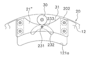
-第3実施形態-
図11は第3実施形態によるトルク変動抑制装置の一部を示しており、第1実施形態の図2及び第2実施形態の図8に相当する図である。この第3実施形態では、規制機構の構成のみが第2実施形態と異なる。すなわち、第3実施形態の規制機構23’’は、ピン231’と遠心子21’’の内周面に形成された規制面232’’とから構成されている。ピン231’は第2実施形態と同様である。規制面232’’は、遠心子21’’の内周面であり、この規制面232’’がピン231’に当接している。規制面232’’は、内周側に凸の円弧状に形成されている。
図11は第3実施形態によるトルク変動抑制装置の一部を示しており、第1実施形態の図2及び第2実施形態の図8に相当する図である。この第3実施形態では、規制機構の構成のみが第2実施形態と異なる。すなわち、第3実施形態の規制機構23’’は、ピン231’と遠心子21’’の内周面に形成された規制面232’’とから構成されている。ピン231’は第2実施形態と同様である。規制面232’’は、遠心子21’’の内周面であり、この規制面232’’がピン231’に当接している。規制面232’’は、内周側に凸の円弧状に形成されている。
なお、前記各実施形態と同様に、ピン231’が規制面232’’のどこの位置に接触していても、遠心子21’の内周面がハブフランジ12の凹部121aの底面に当接しないように規制面232’’の形状が設定されている。
ここでは、回転停止時に、遠心子21’’は、規制面232’’がピン231’に当接することにより、内周側への移動が規制される。このため、遠心子21’’の内周面が凹部121aの底面に衝突することはなく、回転停止時の打音を避けることができる。
-第4実施形態-
図12は第4実施形態によるトルク変動抑制装置の一部を示しており、第1実施形態の図2に相当する図である。この第4実施形態では、規制機構の構成のみが第1実施形態と異なる。すなわち、第4実施形態では、ピン321の外周面には弾性体233が設けられている。
図12は第4実施形態によるトルク変動抑制装置の一部を示しており、第1実施形態の図2に相当する図である。この第4実施形態では、規制機構の構成のみが第1実施形態と異なる。すなわち、第4実施形態では、ピン321の外周面には弾性体233が設けられている。
この場合は、ピン231と規制溝232との間に弾性体233が設けられているので、ピン231と規制溝232とが衝突する際に、衝撃が緩和され、衝突時の打音をさらに抑えることができる。
なお、弾性体233は、ピン231の外周面ではなく、規制溝232の内周面、すなわちピン231が当接する面に設けてもよい。
-第5実施形態-
図13に第5実施形態によるトルク変動抑制装置の一部を示しており、第1実施形態の図2に相当する図である。この第5実施形態では、規制機構の構成のみが第1実施形態と異なる。すなわち、第5実施形態の規制機構23’’’は、ローラ26a,26bを支持するピン(規制軸)27’と、第1及び第2イナーシャリング201,202に形成された溝(規制溝)232’’’と、を有している。
図13に第5実施形態によるトルク変動抑制装置の一部を示しており、第1実施形態の図2に相当する図である。この第5実施形態では、規制機構の構成のみが第1実施形態と異なる。すなわち、第5実施形態の規制機構23’’’は、ローラ26a,26bを支持するピン(規制軸)27’と、第1及び第2イナーシャリング201,202に形成された溝(規制溝)232’’’と、を有している。
ピン27’は、遠心子21及び第1及び第2イナーシャリング201,202の溝232’’’を回転軸方向に貫通して設けられている。溝232’’’は、第1イナーシャリング201及び第2イナーシャリング202のそれぞれに、同じ位置に同じ形状で形成されている。溝232’’’は、外周側に凸の円弧状に形成され、この溝232’’’にピン27’が挿入されている。ピン27’と溝232’’’との間には所定の隙間が設けられており、ピン27’は溝232’’’内をスムーズに移動することが可能である。
[他の実施形態]
本発明は以上のような実施形態に限定されるものではなく、本発明の範囲を逸脱することなく種々の変形又は修正が可能である。
本発明は以上のような実施形態に限定されるものではなく、本発明の範囲を逸脱することなく種々の変形又は修正が可能である。
(a)前記実施形態では、イナーシャリングを連続した円環状の部材で構成したが、分割された複数のイナーシャ体を円周方向に並べて配置してもよい。この場合は、複数のイナーシャ体を保持するために、イナーシャ体の外周側に、円環状の保持リング等の保持部材を設ける必要がある。
(b)前記実施形態では、ガイド部としてガイドローラを配置したが、樹脂レースやシート等の摩擦を低減する他の部材を配置してもよい。
[適用例]
以上のようなトルク変動抑制装置を、トルクコンバータや他の動力伝達装置に適用する場合、種々の配置が可能である。以下に、トルクコンバータや他の動力伝達装置の模式図を利用して、具体的な適用例について説明する。
以上のようなトルク変動抑制装置を、トルクコンバータや他の動力伝達装置に適用する場合、種々の配置が可能である。以下に、トルクコンバータや他の動力伝達装置の模式図を利用して、具体的な適用例について説明する。
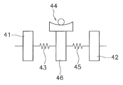
(1)図14は、トルクコンバータを模式的に示した図であり、トルクコンバータは、入力側回転体41と、ハブフランジ42と、入力側回転体41及びハブフランジ42の間に設けられたダンパ43と、を有している。入力側回転体41は、フロントカバー、ドライブプレート、ピストン等の部材を含む。ハブフランジ42は、ドリブンプレート、タービンハブを含む。ダンパ43は複数のトーションスプリングを含む。
この図14に示した例では、入力側回転体41を構成する回転部材のいずれかに遠心子が設けられており、この遠心子に作用する遠心力を利用して作動するカム機構及び規制機構44が設けられている。カム機構及び規制機構44については、前記各実施形態に示された構成と同様の構成を適用できる。
(2)図15に示したトルクコンバータは、ハブフランジ42を構成する回転部材のいずれかに遠心子が設けられており、この遠心子に作用する遠心力を利用して作動するカム機構及び規制機構44が設けられている。カム機構及び規制機構44については、前記各実施形態に示された構成と同様の構成を適用できる。
(3)図16に示したトルクコンバータは、図14及び図15に示した構成に加えて、別のダンパ45と、2つのダンパ43,45の間に設けられた中間部材46と、を有している。中間部材46は、入力側回転体41及びハブフランジ42と相対回転自在であり、2つのダンパ43,45を直列的に作用させる。
図16に示した例では、中間部材46に遠心子が設けられており、この遠心子に作用する遠心力を利用して作動するカム機構及び規制機構44が設けられている。カム機構及び規制機構44については、前記各実施形態に示された構成と同様の構成を適用できる。
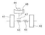
(4)図17に示したトルクコンバータは、フロート部材47を有している。フロート部材47は、ダンパ43を構成するトーションスプリングを支持するために部材であり、例えば、環状に形成されて、トーションスプリングの外周及び少なくとも一方の側面を覆うように配置されている。また、フロート部材47は、入力側回転体41及びハブフランジ42と相対回転自在であり、かつダンパ43のトーションスプリングとの摩擦によってダンパ43に連れ回る。すなわち、フロート部材47も回転する。
この図17に示した例では、フロート部材47に遠心子48が設けられており、この遠心子48に作用する遠心力を利用して作動するカム機構及び規制機構44が設けられている。カム機構及び規制機構44については、前記各実施形態に示された構成と同様の構成を適用できる。
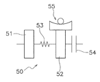
(5)図18は、2つの慣性体51,52を有するフライホイール50と、クラッチ装置54と、を有する動力伝達装置の模式図である。すなわち、エンジンとクラッチ装置54との間に配置されたフライホイール50は、第1慣性体51と、第1慣性体51と相対回転自在に配置された第2慣性体52と、2つの慣性体51,52の間に配置されたダンパ53と、を有している。なお、第2慣性体52は、クラッチ装置54を構成するクラッチカバーも含む。
図18に示した例では、第2慣性体52を構成する回転部材のいずれかに遠心子が設けられており、この遠心子に作用する遠心力を利用して作動するカム機構及び規制機構55が設けられている。カム機構及び規制機構55については、前記各実施形態に示された構成と同様の構成を適用できる。
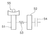
(6)図19は、図18と同様の動力伝達装置において、第1慣性体51に遠心子が設けられた例である。そして、この遠心子に作用する遠心力を利用して作動するカム機構及び規制機構55が設けられている。カム機構及び規制機構55については、前記各実施形態に示された構成と同様の構成を適用できる。
(7)図20に示した動力伝達装置は、図18及び図19に示した構成に加えて、別のダンパ56と、2つのダンパ53,56の間に設けられた中間部材57と、を有している。中間部材57は、第1慣性体51及び第2慣性体52と相対回転自在である。
図20に示した例では、中間部材57に遠心子58が設けられており、この遠心子58に作用する遠心力を利用して作動するカム機構及び規制機構55が設けられている。カム機構及び規制機構55については、前記各実施形態に示された構成と同様の構成を適用できる。
(8)図21は、1つのフライホイールにクラッチ装置が設けられた動力伝達装置の模式図である。図21の第1慣性体61は、1つのフライホイールと、クラッチ装置62のクラッチカバーと、を含む。この例では、第1慣性体61を構成する回転部材のいずれかに遠心子が設けられており、この遠心子に作用する遠心力を利用して作動するカム機構及び規制機構64が設けられている。カム機構及び規制機構64については、前記各実施形態に示された構成と同様の構成を適用できる。
(9)図22は、図21と同様の動力伝達装置において、クラッチ装置62の出力側に遠心子65が設けられた例である。そして、この遠心子65に作用する遠心力を利用して作動するカム機構及び規制機構64が設けられている。カム機構及び規制機構64については、前記各実施形態に示された構成と同様の構成を適用できる。
(10)図面には示していないが、本発明のトルク変動抑制装置を、トランスミッションを構成する回転部材のいずれかに配置してもよいし、さらにはトランスミッションの出力側のシャフト(プロペラシャフト又はドライブシャフト)に配置してもよい。
(11)他の適用例として、従来から周知のダイナミックダンパ装置や、振り子式ダンパ装置が設けられた動力伝達装置に、本発明のトルク変動抑制装置をさらに適用してもよい。
本発明では、回転部材のトルク変動を抑えるための装置において、比較的広い回転数域においてトルク変動のピークを抑えることができる。また、本発明では、遠心子が他の部材と衝突する打音を抑えることができる。
1 トルクコンバータ
11 入力側回転体
12,120 ハブフランジ(回転体)
121a 開口部
14,14’ トルク変動抑制装置
20,201,202 イナーシャリング(質量体)
21,21’,21’’ 遠心子
22,22 カム機構
23、23’,23’’,23’’’ 規制機構
231,231’ ピン(規制軸)
232,232’,232’’’ 溝(規制溝)
232’’ 規制面
30 コロ(カムフォロア)
31 カム
11 入力側回転体
12,120 ハブフランジ(回転体)
121a 開口部
14,14’ トルク変動抑制装置
20,201,202 イナーシャリング(質量体)
21,21’,21’’ 遠心子
22,22 カム機構
23、23’,23’’,23’’’ 規制機構
231,231’ ピン(規制軸)
232,232’,232’’’ 溝(規制溝)
232’’ 規制面
30 コロ(カムフォロア)
31 カム
Claims (9)
- トルクが入力される回転体のトルク変動を抑制するトルク変動抑制装置であって、
前記回転体とともに回転可能であり、かつ前記回転体に対して相対回転自在に配置された質量体と、
前記回転体及び前記質量体の回転による遠心力を受けるように配置された複数の遠心子と、
前記遠心子に作用する遠心力を受けて、前記回転体と前記質量体との間に回転方向における相対変位が生じたときには、前記遠心力を、前記相対変位が小さくなる方向の円周方向力に変換する複数のカム機構と、
前記カム機構による前記遠心子の作動を許容し、かつ前記遠心子の径方向の移動を規制する複数の規制機構と、
備えたトルク変動抑制装置。 - 前記規制機構は、
前記質量体及び前記遠心子の一方に設けられ、前記回転体の回転軸に沿って延びる規制軸と、
前記質量体及び前記遠心子の他方に形成され、前記規制軸が挿入された規制溝と、
を有する、
請求項1に記載のトルク変動抑制装置。 - 前記規制機構は、
前記質量体に設けられ、前記回転体の回転軸に沿って延びる規制軸と、
前記遠心子の内周面に形成され、前記規制軸が摺動する規制面と、
を有する、
請求項1に記載のトルク変動抑制装置。 - 前記規制軸の外周面又は前記規制軸が当接する面に設けられた弾性体をさらに備えた、請求項2又は3に記載のトルク変動抑制装置。
- 前記回転体は、外周面に複数の凹部を有し、
複数の前記遠心子のそれぞれは、前記回転体の凹部に収容されており、
前記規制機構は、前記遠心子の内周面が前記凹部の底面に当接するのを規制する、
請求項1から4のいずれかに記載のトルク変動抑制装置。 - 前記カム機構は、
前記質量体及び前記遠心子の一方に設けられたカムと、
前記質量体及び前記遠心子の他方に設けられ前記カムに沿って移動するカムフォロアと、を有する、
請求項1から5のいずれかに記載のトルク変動抑制装置。 - 前記質量体は、前記回転体を挟んで対向して配置された第1イナーシャリング及び第2イナーシャリングと、前記第1イナーシャリングと前記第2イナーシャリングとを相対回転不能に連結するピンと、を有し、
前記遠心子は、前記回転体の外周部でかつ前記ピンの内周側において前記第1イナーシャリングと前記第2イナーシャリングとの軸方向間に配置されており、
前記カムフォロアは、内部に前記ピンが軸方向に貫通する孔を有する円筒状のコロであり、
前記カムは、前記遠心子に形成されて前記カムフォロアに当接し、前記回転体と前記質量体との間の回転方向における相対変位量に応じて前記円周方向力が変化するような形状を有する、
請求項1から6のいずれかに記載のトルク変動抑制装置。 - エンジンとトランスミッションとの間に配置されるトルクコンバータであって、
前記エンジンからのトルクが入力される入力側回転体と、
前記トランスミッションにトルクを出力する出力側回転体と、
前記入力側回転体と前記タービンとの間に配置されたダンパと、
請求項1から7のいずれかに記載のトルク変動抑制装置と、
を備えたトルクコンバータ。 - 回転軸を中心に回転する第1慣性体と、前記回転軸を中心に回転し前記第1慣性体と相対回転自在な第2慣性体と、前記第1慣性体と前記第2慣性体との間に配置されたダンパと、を有するフライホイールと、
前記フライホイールの前記第2慣性体に設けられたクラッチ装置と、
請求項1から7のいずれかに記載のトルク変動抑制装置と、
を備えた動力伝達装置。
Priority Applications (2)
| Application Number | Priority Date | Filing Date | Title |
|---|---|---|---|
| CN201880012220.2A CN110300862B (zh) | 2017-02-17 | 2018-01-15 | 转矩变动抑制装置、变矩器以及动力传递装置 |
| US16/473,618 US11156277B2 (en) | 2017-02-17 | 2018-01-15 | Torque fluctuation inhibiting device, torque converter and power transmission device |
Applications Claiming Priority (2)
| Application Number | Priority Date | Filing Date | Title |
|---|---|---|---|
| JP2017027688A JP6774352B2 (ja) | 2017-02-17 | 2017-02-17 | トルク変動抑制装置、トルクコンバータ、及び動力伝達装置 |
| JP2017-027688 | 2017-02-17 |
Publications (1)
| Publication Number | Publication Date |
|---|---|
| WO2018150777A1 true WO2018150777A1 (ja) | 2018-08-23 |
Family
ID=63170550
Family Applications (1)
| Application Number | Title | Priority Date | Filing Date |
|---|---|---|---|
| PCT/JP2018/000754 WO2018150777A1 (ja) | 2017-02-17 | 2018-01-15 | トルク変動抑制装置、トルクコンバータ、及び動力伝達装置 |
Country Status (4)
| Country | Link |
|---|---|
| US (1) | US11156277B2 (ja) |
| JP (1) | JP6774352B2 (ja) |
| CN (1) | CN110300862B (ja) |
| WO (1) | WO2018150777A1 (ja) |
Cited By (2)
| Publication number | Priority date | Publication date | Assignee | Title |
|---|---|---|---|---|
| EP3839291A4 (en) * | 2018-11-20 | 2021-11-03 | Aisin Aw Co., Ltd. | VIBRATION DAMPING DEVICE AND METHOD OF DESIGNING THE SAME |
| US20220010794A1 (en) * | 2020-07-07 | 2022-01-13 | Exedy Corporation | Rotary device and power transmission device |
Families Citing this family (6)
| Publication number | Priority date | Publication date | Assignee | Title |
|---|---|---|---|---|
| JP7047683B2 (ja) | 2018-09-14 | 2022-04-05 | トヨタ自動車株式会社 | 捩り振動低減装置 |
| JP7208826B2 (ja) * | 2019-02-25 | 2023-01-19 | 株式会社エクセディ | 回転装置 |
| JP7263066B2 (ja) | 2019-03-13 | 2023-04-24 | 株式会社エクセディ | トルク変動抑制装置、及びトルクコンバータ |
| JP7218221B2 (ja) * | 2019-03-13 | 2023-02-06 | 株式会社エクセディ | トルク変動抑制装置、及びトルクコンバータ |
| JP2021071190A (ja) * | 2019-11-01 | 2021-05-06 | 株式会社エクセディ | トルク変動抑制装置及び動力伝達装置 |
| JP7342969B2 (ja) * | 2019-11-08 | 2023-09-12 | 日産自動車株式会社 | 内燃機関の制御方法及び内燃機関の制御装置 |
Citations (7)
| Publication number | Priority date | Publication date | Assignee | Title |
|---|---|---|---|---|
| JPH062048Y2 (ja) * | 1987-02-23 | 1994-01-19 | トヨタ自動車株式会社 | ト−シヨナルダンパ付フライホイ−ル |
| JP2010071341A (ja) * | 2008-09-17 | 2010-04-02 | Toyota Motor Corp | 振子式動吸振装置 |
| JP2014020467A (ja) * | 2012-07-18 | 2014-02-03 | Aisin Aw Industries Co Ltd | 回転体の振動低減装置 |
| JP5571513B2 (ja) * | 2010-09-16 | 2014-08-13 | アイシン・エィ・ダブリュ工業株式会社 | 動吸振器 |
| JP2014145413A (ja) * | 2013-01-29 | 2014-08-14 | Toyota Motor Corp | 捩り振動減衰装置 |
| JP2015057565A (ja) * | 2013-08-09 | 2015-03-26 | アイシン・エィ・ダブリュ株式会社 | 遠心振子式吸振装置 |
| JP2015083847A (ja) * | 2013-10-25 | 2015-04-30 | 株式会社エクセディ | ダイナミックダンパ装置及びトルクコンバータのロックアップ装置 |
Family Cites Families (8)
| Publication number | Priority date | Publication date | Assignee | Title |
|---|---|---|---|---|
| US4947706A (en) | 1986-09-05 | 1990-08-14 | Toyota Jidosha Kabushiki Kaisha | Flywheel with a torsional damper |
| FR2989753B1 (fr) * | 2012-04-20 | 2014-04-18 | Valeo Embrayages | Dispositif d'amortissement pendulaire, en particulier pour une transmission de vehicule automobile |
| DE112013003401A5 (de) * | 2012-07-06 | 2015-04-23 | Schaeffler Technologies Gmbh & Co. Kg | Fliehkraftpendel |
| DE102013213373A1 (de) * | 2013-07-09 | 2015-01-15 | Zf Friedrichshafen Ag | Tilgerschwingungsdämpfer |
| CN105378335B (zh) | 2013-08-09 | 2017-02-01 | 爱信艾达株式会社 | 离心振子式吸振装置 |
| JP6182434B2 (ja) | 2013-11-12 | 2017-08-16 | 株式会社エクセディ | トルクコンバータのロックアップ装置 |
| FR3014982B1 (fr) | 2013-12-16 | 2016-03-11 | Valeo Embrayages | Dispositif d'amortissement pendulaire |
| JP2021071190A (ja) * | 2019-11-01 | 2021-05-06 | 株式会社エクセディ | トルク変動抑制装置及び動力伝達装置 |
-
2017
- 2017-02-17 JP JP2017027688A patent/JP6774352B2/ja active Active
-
2018
- 2018-01-15 CN CN201880012220.2A patent/CN110300862B/zh active Active
- 2018-01-15 US US16/473,618 patent/US11156277B2/en active Active
- 2018-01-15 WO PCT/JP2018/000754 patent/WO2018150777A1/ja active Application Filing
Patent Citations (7)
| Publication number | Priority date | Publication date | Assignee | Title |
|---|---|---|---|---|
| JPH062048Y2 (ja) * | 1987-02-23 | 1994-01-19 | トヨタ自動車株式会社 | ト−シヨナルダンパ付フライホイ−ル |
| JP2010071341A (ja) * | 2008-09-17 | 2010-04-02 | Toyota Motor Corp | 振子式動吸振装置 |
| JP5571513B2 (ja) * | 2010-09-16 | 2014-08-13 | アイシン・エィ・ダブリュ工業株式会社 | 動吸振器 |
| JP2014020467A (ja) * | 2012-07-18 | 2014-02-03 | Aisin Aw Industries Co Ltd | 回転体の振動低減装置 |
| JP2014145413A (ja) * | 2013-01-29 | 2014-08-14 | Toyota Motor Corp | 捩り振動減衰装置 |
| JP2015057565A (ja) * | 2013-08-09 | 2015-03-26 | アイシン・エィ・ダブリュ株式会社 | 遠心振子式吸振装置 |
| JP2015083847A (ja) * | 2013-10-25 | 2015-04-30 | 株式会社エクセディ | ダイナミックダンパ装置及びトルクコンバータのロックアップ装置 |
Cited By (3)
| Publication number | Priority date | Publication date | Assignee | Title |
|---|---|---|---|---|
| EP3839291A4 (en) * | 2018-11-20 | 2021-11-03 | Aisin Aw Co., Ltd. | VIBRATION DAMPING DEVICE AND METHOD OF DESIGNING THE SAME |
| US20220010794A1 (en) * | 2020-07-07 | 2022-01-13 | Exedy Corporation | Rotary device and power transmission device |
| US11927254B2 (en) * | 2020-07-07 | 2024-03-12 | Exedy Corporation | Rotary device and power transmission device |
Also Published As
| Publication number | Publication date |
|---|---|
| US20190323576A1 (en) | 2019-10-24 |
| JP6774352B2 (ja) | 2020-10-21 |
| JP2018132160A (ja) | 2018-08-23 |
| CN110300862A (zh) | 2019-10-01 |
| US11156277B2 (en) | 2021-10-26 |
| CN110300862B (zh) | 2021-05-11 |
Similar Documents
| Publication | Publication Date | Title |
|---|---|---|
| WO2018150777A1 (ja) | トルク変動抑制装置、トルクコンバータ、及び動力伝達装置 | |
| WO2017043316A1 (ja) | トルク変動抑制装置、トルクコンバータ、及び動力伝達装置 | |
| WO2017029932A1 (ja) | トルク変動抑制装置、トルクコンバータ、及び動力伝達装置 | |
| JP6657041B2 (ja) | トルク変動抑制装置、トルクコンバータ、及び動力伝達装置 | |
| JP6653538B2 (ja) | トルク変動抑制装置、トルクコンバータ、及び動力伝達装置 | |
| WO2018150660A1 (ja) | トルク変動抑制装置、トルクコンバータ、及び動力伝達装置 | |
| JP6757680B2 (ja) | トルク変動抑制装置、トルクコンバータ、及び動力伝達装置 | |
| WO2018016212A1 (ja) | トルク変動抑制装置、トルクコンバータ、及び動力伝達装置 | |
| JP2019039456A (ja) | トルク変動抑制装置、トルクコンバータ、及び動力伝達装置 | |
| US10808797B2 (en) | Torque fluctuation inhibiting device, torque converter and power transmission device | |
| JP2019039456A5 (ja) | ||
| JP2019108950A (ja) | トルク変動抑制装置、トルクコンバータ、及び動力伝達装置 | |
| JP6577823B2 (ja) | トルク変動抑制装置、トルクコンバータ、及び動力伝達装置 | |
| JP6539180B2 (ja) | トルク変動抑制装置、トルクコンバータ、及び動力伝達装置 | |
| JP6656868B2 (ja) | トルク変動抑制装置、トルクコンバータ、及び動力伝達装置 | |
| JP7376291B2 (ja) | トルク変動抑制装置、及び動力伝達装置 | |
| JP2019052714A (ja) | トルク変動抑制装置、トルクコンバータ、及び動力伝達装置 | |
| JP6709770B2 (ja) | トルク変動抑制装置及びトルクコンバータ | |
| JP6682572B2 (ja) | トルク変動抑制装置 | |
| JP2020076505A (ja) | トルク変動抑制装置、トルクコンバータ、及び動力伝達装置 | |
| JP2020139522A (ja) | トルク変動抑制装置 | |
| JP2019138421A (ja) | トルク変動抑制装置、トルクコンバータ、及び動力伝達装置 |
Legal Events
| Date | Code | Title | Description |
|---|---|---|---|
| 121 | Ep: the epo has been informed by wipo that ep was designated in this application |
Ref document number: 18754002 Country of ref document: EP Kind code of ref document: A1 |
|
| NENP | Non-entry into the national phase |
Ref country code: DE |
|
| 122 | Ep: pct application non-entry in european phase |
Ref document number: 18754002 Country of ref document: EP Kind code of ref document: A1 |