WO2017022206A1 - 自動二輪車用空気入りタイヤ - Google Patents
自動二輪車用空気入りタイヤ Download PDFInfo
- Publication number
- WO2017022206A1 WO2017022206A1 PCT/JP2016/003452 JP2016003452W WO2017022206A1 WO 2017022206 A1 WO2017022206 A1 WO 2017022206A1 JP 2016003452 W JP2016003452 W JP 2016003452W WO 2017022206 A1 WO2017022206 A1 WO 2017022206A1
- Authority
- WO
- WIPO (PCT)
- Prior art keywords
- tire
- tread
- groove
- circumferential direction
- width direction
- Prior art date
Links
Images


Classifications
-
- B—PERFORMING OPERATIONS; TRANSPORTING
- B60—VEHICLES IN GENERAL
- B60C—VEHICLE TYRES; TYRE INFLATION; TYRE CHANGING; CONNECTING VALVES TO INFLATABLE ELASTIC BODIES IN GENERAL; DEVICES OR ARRANGEMENTS RELATED TO TYRES
- B60C11/00—Tyre tread bands; Tread patterns; Anti-skid inserts
- B60C11/03—Tread patterns
- B60C11/0327—Tread patterns characterised by special properties of the tread pattern
- B60C11/033—Tread patterns characterised by special properties of the tread pattern by the void or net-to-gross ratios of the patterns
-
- B—PERFORMING OPERATIONS; TRANSPORTING
- B60—VEHICLES IN GENERAL
- B60C—VEHICLE TYRES; TYRE INFLATION; TYRE CHANGING; CONNECTING VALVES TO INFLATABLE ELASTIC BODIES IN GENERAL; DEVICES OR ARRANGEMENTS RELATED TO TYRES
- B60C11/00—Tyre tread bands; Tread patterns; Anti-skid inserts
- B60C11/03—Tread patterns
- B60C11/0302—Tread patterns directional pattern, i.e. with main rolling direction
-
- B—PERFORMING OPERATIONS; TRANSPORTING
- B60—VEHICLES IN GENERAL
- B60C—VEHICLE TYRES; TYRE INFLATION; TYRE CHANGING; CONNECTING VALVES TO INFLATABLE ELASTIC BODIES IN GENERAL; DEVICES OR ARRANGEMENTS RELATED TO TYRES
- B60C11/00—Tyre tread bands; Tread patterns; Anti-skid inserts
- B60C11/03—Tread patterns
- B60C2011/0337—Tread patterns characterised by particular design features of the pattern
- B60C2011/0339—Grooves
- B60C2011/0341—Circumferential grooves
- B60C2011/0346—Circumferential grooves with zigzag shape
-
- B—PERFORMING OPERATIONS; TRANSPORTING
- B60—VEHICLES IN GENERAL
- B60C—VEHICLE TYRES; TYRE INFLATION; TYRE CHANGING; CONNECTING VALVES TO INFLATABLE ELASTIC BODIES IN GENERAL; DEVICES OR ARRANGEMENTS RELATED TO TYRES
- B60C11/00—Tyre tread bands; Tread patterns; Anti-skid inserts
- B60C11/03—Tread patterns
- B60C2011/0337—Tread patterns characterised by particular design features of the pattern
- B60C2011/0339—Grooves
- B60C2011/0358—Lateral grooves, i.e. having an angle of 45 to 90 degees to the equatorial plane
-
- B—PERFORMING OPERATIONS; TRANSPORTING
- B60—VEHICLES IN GENERAL
- B60C—VEHICLE TYRES; TYRE INFLATION; TYRE CHANGING; CONNECTING VALVES TO INFLATABLE ELASTIC BODIES IN GENERAL; DEVICES OR ARRANGEMENTS RELATED TO TYRES
- B60C11/00—Tyre tread bands; Tread patterns; Anti-skid inserts
- B60C11/03—Tread patterns
- B60C2011/0337—Tread patterns characterised by particular design features of the pattern
- B60C2011/0339—Grooves
- B60C2011/0381—Blind or isolated grooves
-
- B—PERFORMING OPERATIONS; TRANSPORTING
- B60—VEHICLES IN GENERAL
- B60C—VEHICLE TYRES; TYRE INFLATION; TYRE CHANGING; CONNECTING VALVES TO INFLATABLE ELASTIC BODIES IN GENERAL; DEVICES OR ARRANGEMENTS RELATED TO TYRES
- B60C2200/00—Tyres specially adapted for particular applications
- B60C2200/10—Tyres specially adapted for particular applications for motorcycles, scooters or the like
Definitions
- This invention relates to a pneumatic tire for a motorcycle.
- an object of the present invention is to provide a pneumatic tire for a motorcycle having improved durability while maintaining the steering stability of the tire.
- the configuration of the present invention is as follows.
- the pneumatic tire for a motorcycle according to the present invention includes a tire mounted on an applied rim, filled with a specified internal pressure, and in a reference state in which no load is applied, from the tire equator surface to the tread end side, along the periphery of the tread surface.
- the tire width direction region in the tread tread that is sandwiched between the tire width direction position of the tread tread that is spaced 50% of the half width of the peripheral length of the tread tread and the tread tread that is also 82% apart
- the intermediate region in each half of the tire is provided with a recess intermittently along the tire circumferential direction, and the negative rate in the intermediate region is 15% or more and 45% or less.
- the “applicable rim” is an industrial standard effective for the region where tires are produced and used.
- JATMA Joint Automobile Tire Association
- JATMA YEAR BOOK and in Europe, ETRTO (The European Tire).
- YEAR BOOK “Design Rim”.
- the “specified internal pressure” means the air pressure corresponding to the maximum load capacity in the applicable size / ply rating described in the above JATMA YEAR BOOK etc., and the “maximum load capacity” The maximum mass allowed to be loaded.
- the “negative rate” means the ratio of the recessed area in the intermediate area to the area of the intermediate area tread area ⁇ (recessed area / tread area) ⁇ 100 (%) ⁇ .
- the “circumferential groove extending in the tire circumferential direction” means an inclination angle of 30 ° or less with respect to the tire circumferential direction, and the tire circumferential direction length of the groove in the intermediate region is the tire width direction length.
- the “width direction groove extending in the tire width direction” means an inclination angle of 30 ° or less with respect to the tire width direction, and the tire width direction length of the groove in the intermediate region is the tire circumferential length.
- small hole means a hole having a diameter in the range of 10 mm or more and 20 mm or less, which is not the circumferential groove and the width groove.
- the “pattern pitch” means a tire circumferential length per unit of a tread pattern repeated in the tire circumferential direction, and the tire circumferential length per unit varies in the tire circumferential direction. In such cases, the average length shall be indicated.
- FIG. 1 is a sectional view in the tire width direction of a pneumatic tire for a motorcycle according to an embodiment of the present invention.
- FIG. 2 is a partial development view of a tread surface of the pneumatic tire for a motorcycle in FIG. 1.
- FIG. 3 is a partial development view of a tread surface of a pneumatic tire for a motorcycle according to another embodiment of the present invention.
- FIG. 5 is a partial cross-sectional view of a tread surface of a motorcycle pneumatic tire according to still another embodiment of the present invention.
- FIG. 4 is a partial development view of a tread surface of a pneumatic tire for a motorcycle according to another embodiment of the present invention.
- FIG. 6 is a partial development view of a tread surface of a pneumatic tire for a motorcycle according to still another embodiment of the present invention.
- FIG. 1 shows a cross section in the tire width direction of the tire according to an embodiment of the present invention in the above-described reference state (a state in which the tire is mounted on an applied rim, filled with a specified internal pressure, and is unloaded).
- This tire has a carcass 5 straddling between a pair of bead portions 11 as a skeleton, a pair of sidewall portions 12 on the outer side in the tire radial direction of the bead portions 11, and a tread portion 13 straddling between the sidewall portions 12. It has.
- the carcass in this embodiment consists of one layer of plies, two or more layers of plies can also be arranged.
- the inclined belt 3 including the two inclined belt layers 3a and 3b is disposed on the outer side in the tire radial direction of the carcass 5 in the tread portion 13.
- another belt structure may be used.
- the respective cords are inclined with respect to the tire circumferential direction and extend so as to intersect each other.
- FIG. 2 shows a part of the tread tread 6 of the tire of FIG. 1 according to the present embodiment.
- patterns that are line-symmetric with respect to the equator plane CL are arranged on the one side and the other side of the tread tread 6 with the tire equator plane CL as a boundary, and are shifted from each other in the tire circumferential direction X. ing. Therefore, the configuration of the tread tread 6 of this embodiment will be described as a representative of the left half of the tire toward the paper.
- the tire width direction position of the tread tread that is 50% apart from the tire equatorial plane CL toward the tread end TE side along the periphery of the tread tread 6 along the half width Lp of the peripheral length of the tread tread 6.
- the intermediate region A is recessed along the tire circumferential direction (this In the example, the circumferential groove 21 and the lug grooves 22a, 22b) are formed intermittently.
- the circumferential groove 21 intermittently arranged in the present embodiment is linear and extends along the tire circumferential direction
- the circumferential groove 21 has a bent shape, a curved shape, or the like. Or, it may be inclined and extended at an angle of 30 ° or less with respect to the tire circumferential direction.
- channel 21 in this embodiment is the same shape altogether, it is good also as a mutually different shape.
- the lug grooves 22a and 22b are alternately formed over the tire circumferential direction. More specifically, the lug groove 22a extends at an incline with respect to the tire width direction, and both ends of the lug groove 22a end in the tread surface 6 and once in the vicinity of the center in the extending direction of the groove 22a. It bends and extends obliquely with respect to the tire width direction. Similarly, the lug groove 22b has its entire end terminated in the tread surface 6 but is bent and extended twice near the center in the extending direction of the groove.
- the lug groove 22b includes a groove part b1 that is bent twice and extends while being inclined with respect to the tire width direction, and a groove part b2 that communicates with the first groove part b1 and extends in a direction different from the groove part b1.
- the lug grooves 22a and 22b are grooves whose depth is deeper than that of the circumferential groove 21 described above.
- the recesses are formed in the intermediate region A in each of the tire halves in the tire circumferential direction. It is important that the negative rate in the intermediate region A is not less than 15% and not more than 45%.
- the groove surface area of the intermediate region A where the heat generation amount during the vehicle traveling is maximized is increased in the vicinity of the ground contact TE.
- the release of the generated heat can be promoted, and the temperature inside the tire in the vicinity of the ground contact TE can be lowered.
- the groove area in the intermediate region A is increased, the volume of the rubber itself that causes heat generation is also reduced. Therefore, from the viewpoint of reducing the heat generation amount itself, the temperature inside the tire in the vicinity of the ground contact TE is also reduced. Can be reduced. As a result, the occurrence of failure at the belt end and the ply end can be suppressed, and the durability of the tire can be improved.
- the intermittently extending concave portion causes a rigid step in the intermediate region A, and there is a possibility that the steering stability is lowered. Therefore, in the tire according to the present embodiment, by setting the negative rate in the intermediate region A to 15% or more, the heat dissipation effect by the recesses can be sufficiently obtained, but by making it 45% or less, the rigidity step is reduced and the steering is reduced. Maintains stability.
- the temperature inside the tire near the tread end during high-load traveling is reduced as compared with the conventional tire while maintaining steering stability.
- the durability of can be improved.
- the traction performance of the tire can be obtained by providing the lug grooves 22a and 22b.
- the groove depths of the lug grooves 22a and 22b are preferably 5 mm or more and 9 mm or less.
- the “groove depth” in the present embodiment is the maximum depth from the groove opening position of the tread surface in the reference state, and the same applies to various grooves and small holes described below.
- the lug grooves 22a and 22b extend near the tread ground contact end, that is, to the outer side in the tire width direction of the intermediate region A from the outer edge in the tire width direction.
- Such a configuration is preferable from the viewpoint of reducing pattern noise, because part of the lug grooves 22a and 22b on the outer side in the tire width direction is always opened away from the contact surface during normal driving.
- the recess provided in the intermediate region A includes a circumferential groove 21 extending in the tire circumferential direction.
- the circumferential groove 21 in the present embodiment has a tire circumferential direction length of 10 mm or more and 50 mm or less, and a tire width direction length of 5 mm or more and 15 mm or less. It is preferable that 20 or more and 100 or less are provided in the tire circumferential direction in the tire half portion. However, the number is appropriately determined according to the length of the groove side along the circumferential direction of the circumferential groove 21. Moreover, it is preferable that the groove depth of the circumferential groove
- the value obtained by dividing the circumferential circumferential distance L between the circumferential grooves 21 in the tire circumferential direction by the pattern pitch length in the tire circumferential direction is 0.15 or more and 0.5 or less.
- the spacing in the tire circumferential direction of the recesses can be kept moderate to improve steering stability, and by setting it to 0.5 or less, the heat dissipation of the circumferential groove 21 is improved. Can be made.
- FIG. 3 is a partial development view of a tread surface 6 of a pneumatic tire for a motorcycle according to another embodiment of the present invention.
- the same reference number is attached
- a width direction groove 31 is formed instead of the circumferential direction groove 21 of FIG.
- region A includes the width direction groove
- the widthwise grooves 31 that are intermittently arranged in the tire circumferential direction are straight and extend along the tire width direction, but the widthwise grooves 31 are bent or curved. Or extending at an angle of 30 ° or less with respect to the tire width direction. Moreover, all the width direction grooves 31 in the present embodiment have the same shape, but may have different shapes.
- this number is the length of the groove side along the circumferential direction of the circumferential direction groove
- a value obtained by dividing the tire circumferential direction interval L between the widthwise grooves 31 adjacent in the tire circumferential direction by the pattern pitch length in the tire circumferential direction is 0.15 or more and 0.5 or less.
- the spacing in the tire circumferential direction of the recesses can be kept moderately to improve the steering stability, and by setting it to 0.5 or less, the heat dissipation of the width direction groove 31 is improved. Can be made.
- FIG. 4 is a partial development view of a tread surface 6 of a pneumatic tire for a motorcycle according to still another embodiment of the present invention.
- the same components as those in FIG. 2 are denoted by the same reference numerals, and the description thereof is omitted.
- a small hole 41 is formed instead of the circumferential groove 21 of FIG.
- the recess provided in the intermediate region A includes the small hole 41.
- the small hole is preferably a circular shape having a diameter of 10 mm or more and 20 mm or less, and may be an ellipse, a quadrangle, or various shapes combining these.
- the groove depth of the small holes is preferably 2 mm or more and 8 mm or less.
- the number is appropriately determined according to the length of the groove side along the circumferential direction of the small holes 41. It is determined.
- one small hole is provided intermittently along the tire circumferential direction, but a group of small holes composed of a plurality of small holes may be provided intermittently.
- the value obtained by dividing the tire circumferential direction interval L between the small holes 41 adjacent in the tire circumferential direction by the pattern pitch length in the tire circumferential direction is 0.15 or more and 0.5 or less.
- FIG. 5 is a partial development view of a tread surface of a pneumatic tire for a motorcycle according to another embodiment of the present invention.
- the tire of the embodiment shown in FIG. 5 also has the tire structure shown in FIG.
- patterns that are line symmetric with respect to the equatorial plane CL are shifted from each other in the tire circumferential direction X on one side and the other side of the tread surface 6 with respect to the tire equatorial plane CL.
- the configuration of the tread tread 6 of this embodiment will be described as a representative of the left half of the tire toward the paper.
- the intermediate region A includes at least one circumferential groove A branch groove Br composed of 51 (one circumferential groove 51 in the illustrated example) and at least one lateral groove 52 (two lateral grooves 52a and 52b in the illustrated example) is provided in each tire half. It is formed intermittently along the direction.
- the circumferential groove 51 includes a circumferential groove portion extending at an angle of 30 ° or less with respect to the tire circumferential direction in the intermediate region A, and the lateral grooves 52a and 52b are arranged in the tire width direction.
- a lateral groove portion extending at an angle of 30 ° or less is provided in the intermediate region, and communicates with the circumferential groove 51 in the intermediate region A.
- the branch groove Br in the embodiment shown in FIG. 5 has a lateral groove 52a extending from one end portion of the circumferential groove 51 toward the outer side in the tire width direction. 52b extends, and both of the lateral grooves 52a and 52b extend further to the outer side in the tire width direction than the outer end in the tire width direction of the intermediate region A.
- the circumferential groove 51 in the embodiment shown in FIG. 5 is linear and extends along the tire circumferential direction.
- the circumferential groove 51 may have a bent shape, a curved shape, or the like. It may be inclined and extend in the direction at an angle of 30 ° or less.
- the lateral grooves 52a and 52b in the present embodiment are linear, have the same length, and extend while being inclined with respect to the tire width direction.
- the lateral grooves 52a and 52b are bent or curved. It can be made into a shape or can be extended along the tire width direction.
- lug grooves 54 are alternately formed on the tread surface 6 with the branch grooves Br along the tire circumferential direction.
- Both ends of the lug groove 54 are terminated in the tread tread surface 6, but linear groove portions 54a, 54b, 54c having different inclination angles with respect to the tire width direction are configured to communicate with each other.
- the lug groove 54 extends by bending twice.
- the lug groove 54 is a groove having a deeper groove depth than the circumferential groove 51 described above.
- a lateral groove portion extending at an angle of 30 ° or less with respect to the tire width direction is provided in the intermediate region A, and communicated with the circumferential groove 51 in the intermediate region A.
- the branch groove Br is formed intermittently along the tire circumferential direction in each of the tire halves.
- the groove surface area in the intermediate area A where the amount of heat generated during traveling of the vehicle is maximized is increased in the vicinity of the ground contact TE. Can be promoted, and the temperature inside the tire in the vicinity of the ground contact TE can be lowered. Furthermore, if the groove area in the intermediate region A is increased, the volume of the rubber itself that causes heat generation is also reduced. Therefore, from the viewpoint of reducing the heat generation amount itself, the temperature inside the tire in the vicinity of the ground contact TE is also reduced. Can be reduced. As a result, the occurrence of failure at the belt end and the ply end can be suppressed, and the durability of the tire can be improved.
- the tread tread surface 6 extends along the periphery of the tread tread surface 6 from the tire equator to the tread end side even when traveling with a relatively large inclination of the vehicle body when traveling under a heavy load. Therefore, the tread tread surface 6 tends to come into contact only with a position 82% apart from the half width Lp of the peripheral length, that is, near the outer end position in the tire width direction of the intermediate region A. Therefore, in the tire according to the embodiment shown in FIG.
- the end in the tire width direction of the lateral groove 52 arranged in the intermediate region A is outside the tire width direction outer end of the intermediate region A, that is, more than the ground contact end.
- the air taken into the circumferential groove 51 and the lateral groove 52 can be released to the outside through the lateral groove 52.
- the end of the lateral groove 52 in the tire width direction extends from the tire equator to the tread end side, along the periphery of the tread tread surface 6 to the outer side in the tire width direction from a position spaced 86% of the half width Lp of the peripheral length of the tread tread surface 6. More preferably, it is extended.
- This 86% -separated position is equal to the ground contact edge when the vehicle body is tilted to the maximum when traveling under a heavy load, and by extending the lateral groove 52 to the outside in the tire width direction from the position, the above-described effect of the lateral groove 52 is achieved. Can be obtained more reliably.
- the temperature inside the tire near the tread end is lowered as compared with the conventional one, thereby improving the durability of the tire. Can do.
- the groove depths of the circumferential groove 51 and the lateral groove 52 constituting the branch groove Br are 2 mm or more and 8 mm or less. .
- the thickness is 2 mm or more, a sufficient heat dissipation effect can be obtained, and when the thickness is 8 mm or less, steering stability can be maintained.
- the length in the tire width direction along the peripheral 6 is preferably 15 mm or more.
- the traction performance of the tire can be improved by providing the lug groove 54 described above.
- the depth of the lug groove 54 is preferably 4 mm or more and 8 mm or less.
- the tire width direction length along the periphery of the tread tread surface 6 of the lateral groove 52 is preferably 8% or more and 30% or less of the half width of the peripheral length of the tread tread surface 6. .
- the ratio By setting the ratio to 8% or more, the durability of the tire can be further improved while maintaining the noise performance more reliably.
- the ratio By setting the ratio to 30% or less, the steering stability can be more reliably maintained. .
- the tire circumferential length along the peripheral of the tread surface 6 of the circumferential groove 51 is preferably 20 mm or more and 80 mm or less.
- the tire circumferential length along the peripheral of the tread surface 6 of the circumferential groove 51 is preferably 20 mm or more and 80 mm or less.
- the value obtained by dividing the interval L between the branch grooves Br adjacent in the tire circumferential direction by the pattern pitch length in the tire circumferential direction is 0.15 or more and 0.8 or less. Preferably there is. If it is 0.15 or more, the heat dissipation effect by the branch groove Br can be further improved, and if it is 0.8 or less, the steering stability of the tire can be more reliably maintained.
- the negative rate in the tire width direction region between the tread end TE is preferably 15% or more and 35% or less. If it is 15% or more, a sufficient heat dissipation effect can be obtained and the durability of the tire can be further improved, and if it is 35% or less, steering stability can be more reliably maintained.
- the “negative rate” in this paragraph means the position in the tire width direction of the tread tread that is 50% apart from the tire equatorial plane to the tread end side along the periphery of the tread tread.
- the ratio of the groove area in the tire width direction region to the area of the tread tread sandwiched between the tread ends ⁇ (groove area / tread area) ⁇ 100 (%) ⁇ .
- the number of branch grooves Br formed on the tread surface 6 is preferably 20 or more and 60 or less. If the number is 20 or more, a sufficient heat dissipation effect can be obtained by the branch groove Br, and the durability of the tire can be further improved. If the number is 60 or less, the steering stability can be more reliably maintained. .
- the number of branch grooves Br can be appropriately set in the range of 20 to 60, for example, according to the length of the circumferential groove 51 described above.
- the branch groove Br in the embodiment shown in FIG. 5 includes two lateral grooves 52a and 52b extending from one end and the other end of the circumferential groove 51 toward the outer side in the tire width direction as described above. It is a U-shaped groove. According to this configuration, it is possible to further improve the durability of the tire while more reliably maintaining the steering stability and noise performance of the tire.
- the branch groove Br is different from the other configurations. You can also
- FIG. 6 is a partial development view of a tread surface of a pneumatic tire for a motorcycle according to still another embodiment of the present invention.
- the branch groove 6Br is provided with a circumferential groove 61, one end portion of the circumferential groove 61, the other end portion, and an interval between them toward the outside in the tire width direction. It is also possible to form three lateral grooves 62a, 62b, and 62c extending in the direction.
- Example 1 Invention tires and comparative tires (both tire sizes are 180 / 60R16M / C) were prototyped under the specifications shown in Table 1, and the durability, steering stability and uneven wear resistance of the tires were evaluated.
- the circumferential grooves 21 and the small holes 41 are arranged so as to overlap in the tire circumferential direction. Therefore, in the table, “between the circumferential grooves 21, the width direction grooves 31 and the small holes 41.
- the “interval L / pattern pitch” is shown as 0.
- Each test tire has a carcass straddling between a pair of bead portions as a skeleton, and a pair of sidewall portions on the outer side in the tire radial direction of the bead portions, and a tread portion straddling the sidewall portions. More specifically, a carcass made of two layers of plies having nylon cords is provided, and two belt layers formed by rubber coating aramid cords on the outer side in the tire radial direction of the carcass, and on the outer side in the tire radial direction. A belt layer made of rubber coated nylon cord.
- the cord angle of the carcass ply with respect to the tire width direction is 15 °
- the cord angle of each belt layer with respect to the tire circumferential direction is 15 °
- the cords of the two belt layers made of aramid cords cross each other between the layers.
- Each test tire was assembled to an applicable rim (MT5.00-16M / C), filled with an internal pressure of 280 kPa, and loaded with a STEP load, and run on a test drum at a speed of 81 km / h.
- the durability of the tire was evaluated by the load until cracks occurred in the above test.
- the tire handling stability was evaluated by feeling test using a test drive by a professional test driver.
- the evaluation of uneven wear resistance of the tire was evaluated by the amount of wear during running at 2000 km.
- Example 2 Invention tires and comparative tires (both tire sizes are 180 / 60R16M / C) were prototyped under the specifications shown in Table 2, and the durability, noise performance, and steering stability of the tires were evaluated.
- Each test tire has a carcass straddling between a pair of bead portions as a skeleton, and a pair of sidewall portions on the outer side in the tire radial direction of the bead portions, and a tread portion straddling the sidewall portions. More specifically, a carcass made of two layers of plies having nylon cords is provided, and two belt layers formed by rubber coating aramid cords on the outer side in the tire radial direction of the carcass, and on the outer side in the tire radial direction. A belt layer made of rubber coated nylon cord.
- the cord angle of the carcass ply with respect to the tire width direction is 15 °
- the cord angle of each belt layer with respect to the tire circumferential direction is 15 °
- the cords of the two belt layers made of aramid cords cross each other between the layers.
- Each test tire was assembled to an applicable rim (MT5.00-16M / C), filled with an internal pressure of 280 kPa, and loaded with a STEP load, and run on a test drum at a speed of 81 km / h.
- the durability of the tire was evaluated by the load until cracks occurred in the above test.
- Tire noise performance evaluation and steering stability evaluation were performed by a test run with a professional test driver and feeling evaluation.
- All the lengths shown in Table 2 are the lengths along the periphery of the tread surface 6.
- the “length (mm) of the outer end in the tire width direction of the lateral groove” in Table 2 is the length in the tire width direction of the end of the lateral groove 52 extending from the intermediate region A to the outer side in the tire width direction.
- “the length of the lateral groove in the tire width direction (%)” indicates the ratio of the length of the tread surface 6 of the lateral groove 52 to the half width Lp of the peripheral length of the tread surface 6.
- the “negative rate (%)” means the tread tread surface that is 50% apart from the tire equatorial plane CL toward the tread end TE side along the periphery of the tread tread surface 6 by a half width Lp of the peripheral length of the tread tread surface 6. The negative rate in the tire width direction region sandwiched between the tire width direction position and the tread end TE is shown.
Landscapes
- Engineering & Computer Science (AREA)
- Mechanical Engineering (AREA)
- Tires In General (AREA)
Abstract
基準状態において、タイヤ赤道面からトレッド端側へ、トレッド踏面のペリフェリに沿って該トレッド踏面のペリフェリ長の半幅の50%離間した、トレッド踏面のタイヤ幅方向位置と、同じく82%離間した、トレッド踏面のタイヤ幅方向位置とで挟まれたトレッド踏面における、タイヤ幅方向領域を中間領域としたとき、タイヤ半部のそれぞれにおける該中間領域に、凹部をタイヤ周方向に沿って断続的に具え、当該中間領域におけるネガティブ率が15%以上45%以下である。
Description
この発明は、自動二輪車用空気入りタイヤに関する。
従来、自動二輪車用空気入りタイヤ(例えば、特許文献1参照)では、特に、比較的高荷重が負荷された状態での走行において、ベルト端やプライ端に破損が生じることに起因するタイヤの耐久性の低下が課題となっていた。
発明者は、ベルト端やプライ端のかような破損の原因は、走行中に、一般に当該ベルト端やプライ端が位置し得るタイヤの接地端付近におけるタイヤ内部の温度が高温になることにあること、および、かかる部分における放熱を促すことがタイヤの耐久性の向上に有効であることを見出した。
従って、タイヤの耐久性を向上させるためには、接地端付近に放熱用の溝等の凹部を設けて、該接地端付近におけるタイヤ内部の温度を低下させることが有効であると考えられる。しかしながら、接地端付近に凹部を設けると、タイヤの操縦安定性が損なわれる虞がある。
そこで、本発明は、タイヤの操縦安定性を維持しつつ耐久性を向上させた自動二輪車用空気入りタイヤを提供することを目的とする。
本発明の構成は、以下のとおりである。
本発明の自動二輪車用空気入りタイヤは、タイヤを適用リムに装着し、規定内圧を充填し、無負荷とした基準状態において、タイヤ赤道面からトレッド端側へ、トレッド踏面のペリフェリに沿って該トレッド踏面のペリフェリ長の半幅の50%離間した、トレッド踏面のタイヤ幅方向位置と、同じく82%離間した、トレッド踏面のタイヤ幅方向位置とで挟まれたトレッド踏面における、タイヤ幅方向領域を中間領域としたとき、タイヤ半部のそれぞれにおける該中間領域に、凹部をタイヤ周方向に沿って断続的に具え、当該中間領域におけるネガティブ率が15%以上45%以下であること、を特徴とする。
本発明の自動二輪車用空気入りタイヤは、タイヤを適用リムに装着し、規定内圧を充填し、無負荷とした基準状態において、タイヤ赤道面からトレッド端側へ、トレッド踏面のペリフェリに沿って該トレッド踏面のペリフェリ長の半幅の50%離間した、トレッド踏面のタイヤ幅方向位置と、同じく82%離間した、トレッド踏面のタイヤ幅方向位置とで挟まれたトレッド踏面における、タイヤ幅方向領域を中間領域としたとき、タイヤ半部のそれぞれにおける該中間領域に、凹部をタイヤ周方向に沿って断続的に具え、当該中間領域におけるネガティブ率が15%以上45%以下であること、を特徴とする。
ここで、上記「適用リム」とは、タイヤが生産され、使用される地域に有効な産業規格であって、日本ではJATMA(日本自動車タイヤ協会)のJATMA YEAR BOOK、欧州ではETRTO (The European Tyre and Rim Technical Organisation, Inc.)のSTANDARDS MANUAL、米国ではTRA (The Tire and Rim Association, Inc.)のYEAR BOOK等に記載されている、適用サイズにおける標準リム(ETRTOのSTANDARDS MANUALではMeasuring Rim、TRAのYEAR BOOKではDesign Rim)を指す。
また、「規定内圧」とは、上記のJATMA YEAR BOOK等に記載されている、適用サイズ・プライレーティングにおける最大負荷能力に対応する空気圧をいい、「最大負荷能力」とは、上記規格でタイヤに負荷されることが許容される最大の質量をいう。
また、「規定内圧」とは、上記のJATMA YEAR BOOK等に記載されている、適用サイズ・プライレーティングにおける最大負荷能力に対応する空気圧をいい、「最大負荷能力」とは、上記規格でタイヤに負荷されることが許容される最大の質量をいう。
なお、上記「ネガティブ率」とは、上記中間領域の踏面の面積に対する該中間領域内の凹部面積の比率{(凹部面積/踏面面積)×100(%)}のことをいう。
本明細書において、「タイヤ周方向に延びる周方向溝」とは、タイヤ周方向に対する傾斜角度が30°以下であり、前記中間領域内での該溝のタイヤ周方向長さがタイヤ幅方向長さの2倍以上である溝をいう。
本明細書において、「タイヤ幅方向に延びる幅方向溝」とは、タイヤ幅方向に対する傾斜角度が30°以下であり、前記中間領域内での該溝のタイヤ幅方向長さがタイヤ周方向長さの2倍以上である溝をいう。
本明細書において、「小穴」とは、上記の周方向溝および幅方向溝でないものであって、径が10mm以上20mm以下の範囲の穴をいう。
本明細書において、「パターンピッチ」とは、タイヤ周方向に繰り返されるトレッド模様の1単位あたりのタイヤ周方向長さをいい、当該1単位当たりのタイヤ周方向長さがタイヤ周方向で変化する場合は、その平均長さを指すものとする。
なお、特に断りのない限り、周方向溝や幅方向溝の長さ等の寸法はすべて、トレッド踏面のペリフェリに沿って測定するものとする。
本発明によれば、タイヤの操縦安定性を維持しつつ耐久性を向上させた、自動二輪車用空気入りタイヤを提供することができる。
以下、図面を参照しながら本発明の自動二輪車用空気入りタイヤ(以下、単に「タイヤ」ともいう)を、その実施形態を例示して詳細に説明する。
図1は、本発明の一実施形態にかかるタイヤの、上記基準状態(タイヤを適用リムに装着し、規定内圧を充填し、無負荷とした状態)におけるタイヤ幅方向断面を示している。このタイヤは、一対のビード部11間に跨るカーカス5を骨格として、該ビード部11のタイヤ径方向外側に一対のサイドウォール部12と、該サイドウォール部12間に跨るトレッド部13と、を具えている。なお、本実施形態におけるカーカスは1層のプライからなるが、2層以上のプライを配置することもできる。また、本実施形態では、トレッド部13におけるカーカス5のタイヤ径方向外側に、2層の傾斜ベルト層3a,3bからなる傾斜ベルト3が配置されているが、他のベルト構造とすることもできる。なお、2層の傾斜ベルト層3a,3bでは、それぞれのコードがタイヤ周方向に対して傾斜しかつ層間で交差して延びている。
図1は、本発明の一実施形態にかかるタイヤの、上記基準状態(タイヤを適用リムに装着し、規定内圧を充填し、無負荷とした状態)におけるタイヤ幅方向断面を示している。このタイヤは、一対のビード部11間に跨るカーカス5を骨格として、該ビード部11のタイヤ径方向外側に一対のサイドウォール部12と、該サイドウォール部12間に跨るトレッド部13と、を具えている。なお、本実施形態におけるカーカスは1層のプライからなるが、2層以上のプライを配置することもできる。また、本実施形態では、トレッド部13におけるカーカス5のタイヤ径方向外側に、2層の傾斜ベルト層3a,3bからなる傾斜ベルト3が配置されているが、他のベルト構造とすることもできる。なお、2層の傾斜ベルト層3a,3bでは、それぞれのコードがタイヤ周方向に対して傾斜しかつ層間で交差して延びている。
図2は、本実施形態に係る図1のタイヤのトレッド踏面6の一部を展開して示している。本実施形態では、タイヤ赤道面CLを境にしてトレッド踏面6の一方側と他方側に、該赤道面CLに対して線対称であるパターンが、タイヤ周方向Xに相互にずらされて配置されている。従って、かかる実施形態のトレッド踏面6の構成について、ここでは紙面に向かって左側のタイヤ半部について代表して説明する。
まず、本実施形態では、タイヤ赤道面CLからトレッド端TE側へ、トレッド踏面6のペリフェリに沿って該トレッド踏面6のペリフェリ長の半幅Lpの50%離間した、トレッド踏面のタイヤ幅方向位置と、同じく82%離間した、トレッド踏面のタイヤ幅方向位置とで挟まれたトレッド踏面における、タイヤ幅方向領域を中間領域Aとしたとき、該中間領域Aに、タイヤ周方向に沿って凹部(この例では周方向溝21とラグ溝22a,22b)が断続的に形成されている。なお、本実施形態において断続的に配置された周方向溝21は直線状であり、タイヤ周方向に沿って延在しているが、該周方向溝21を屈曲形状または湾曲形状等とすることや、タイヤ周方向に対して30°以下の角度で傾斜して延びるものとすることができる。また、本実施形態における周方向溝21はすべて同一の形状であるが、相互に異なる形状としてもよい。
また、上記ラグ溝22a,22bは、タイヤ周方向にわたって交互に形成されている。より具体的には、ラグ溝22aは、タイヤ幅方向に対して傾斜して延び、その両端がトレッド踏面6内で終端している溝であり、該溝22aの延在方向中央付近にて一度屈曲し、タイヤ幅方向に対して傾斜して延びている。ラグ溝22bも同様に、その全端がトレッド踏面6内で終端しているが、該溝の延在方向中心付近にて2度屈曲して延びている。より具体的に、ラグ溝22bは、2度屈曲してタイヤ幅方向に対し傾斜して延びる溝部b1と、第溝部b1に連通して該溝部b1とは異なる方向に延びる溝部b2と、から構成されている。なお、ラグ溝22a,22bは、上記の周方向溝21よりも溝深さが深い溝である。
このように、本発明に係るタイヤでは、適用リム7に装着し、規定内圧を充填し、無負荷とした基準状態において、タイヤ半部のそれぞれにおける前記中間領域Aに、凹部をタイヤ周方向に沿って断続的に形成するとともに、中間領域Aにおけるネガティブ率を15%以上45%以下とすること、が肝要である。
このように、断続して延びる凹部を中間領域Aに設けると、接地端TEの近傍であり、車両走行中における発熱量が最も大きくなる中間領域Aの溝表面積が大きくなるため、タイヤの内部で発生した熱の放出を促し、接地端TE近傍におけるタイヤ内部の温度を低下させることができる。さらには、中間領域A内の溝面積が増加すると、発熱要因となるゴム自体の体積を減じることにもなるため、発熱量それ自体を低減できる観点からも、接地端TE近傍におけるタイヤ内部の温度を低下させることが可能となる。その結果、ベルト端およびプライ端における故障の発生を抑制して、タイヤの耐久性を向上させることができる。
しかしながら、この際、断続して延びる凹部は、該中間領域Aに剛性段差をもたらし、操縦安定性が低下する虞がある。そこで、本実施形態に係るタイヤでは、中間領域Aにおけるネガティブ率を15%以上とすることによって、凹部による放熱効果を十分に得つつも、45%以下とすることによって、剛性段差を低減し操縦安定性を維持している。
以上のように、本発明の一実施形態に係る構成によれば、操縦安定性を維持しつつ、高荷重走行時における、トレッド端付近のタイヤ内部の温度を従来に比し低下させ、もってタイヤの耐久性を向上させることができる。
なお、本実施形態では、上記したラグ溝22a,22bを設けることにより、タイヤのトラクション性能を得ることができる。十分なトラクション性能を得る観点から、ラグ溝22a,22bの溝深さは5mm以上9mm以下であることが好ましい。
なお、本実施形態でいう「溝深さ」は、基準状態におけるトレッド踏面の溝開口位置からの最大深さを測るものとし、以下に記載する各種溝および小穴においても同様である。
なお、本実施形態でいう「溝深さ」は、基準状態におけるトレッド踏面の溝開口位置からの最大深さを測るものとし、以下に記載する各種溝および小穴においても同様である。
さらに、本実施形態では、ラグ溝22a,22bは、トレッド接地端近傍、すなわち中間領域Aのタイヤ幅方向外端縁よりもタイヤ幅方向外側まで延在している。かような構成によれば、通常走行時、ラグ溝22a,22bのタイヤ幅方向外側の一部が常に接地面から外れて開口することになるので、パターンノイズを低減する観点から好ましい。
また、本実施形態に係るタイヤがそうであるように、中間領域Aに設ける凹部がタイヤ周方向に延びる周方向溝21を含むことが好ましい。
なお、本実施形態における周方向溝21は、本実施形態では、タイヤ周方向長さが10mm以上50mm以下であり、タイヤ幅方向長さが5mm以上15mm以下であることが好ましく、また、それぞれのタイヤ半部でタイヤ周方向に亘って20個以上100個以下設けることが好ましい。ただし、かかる個数は、周方向溝21の周方向に沿う溝辺の長さに応じて適宜決定される。
また、周方向溝21の溝深さは、2mm以上8mm以下であることが好ましい。
これらの範囲を満たすことにより、周方向溝21による放熱効果をさらに高めることができる。
また、周方向溝21の溝深さは、2mm以上8mm以下であることが好ましい。
これらの範囲を満たすことにより、周方向溝21による放熱効果をさらに高めることができる。
また、タイヤ周方向に隣接する周方向溝21のタイヤ周方向の間隔Lを、タイヤ周方向のパターンピッチ長さで除した値が0.15以上0.5以下であることが好ましい。0.15以上とすることにより、凹部のタイヤ周方向の間隔を適度に保って操縦安定性をより向上させることができ、0.5以下とすることにより、周方向溝21の放熱性を向上させることができる。
また、図3は、本発明の他の実施形態にかかる自動二輪車用空気入りタイヤのトレッド踏面6の部分展開図である。なお、図2と同様の構成には、同様の参照番号を付してその説明を省略する。図3の実施形態では、図2の周方向溝21に代えて幅方向溝31が形成されている。このように、中間領域Aに設ける凹部が、タイヤ幅方向に延びる幅方向溝31を含むことが好ましい。
なお、本実施形態においてタイヤ周方向に断続的に配置された幅方向溝31は直線状であり、タイヤ幅方向に沿って延在しているが、該幅方向溝31を屈曲形状や湾曲形状等とすることや、タイヤ幅方向に対して30°以下の角度で傾斜して延びるものとすることができる。また、本実施形態における幅方向溝31はすべて同一の形状であるが、相互に異なる形状としてもよい。
なお、幅方向溝31は、それぞれのタイヤ半部で、タイヤ周方向に亘って20個以上100個以下設けることが好ましいが、かかる個数は、周方向溝21の周方向に沿う溝辺の長さに応じて適宜決定される。
また、タイヤ周方向に隣接する幅方向溝31のタイヤ周方向の間隔Lを、タイヤ周方向のパターンピッチ長さで除した値が0.15以上0.5以下であることが好ましい。0.15以上とすることにより、凹部のタイヤ周方向の間隔を適度に保って操縦安定性をより向上させることができ、0.5以下とすることにより、幅方向溝31の放熱性を向上させることができる。
また、図4は、本発明のさらに他の実施形態にかかる自動二輪車用空気入りタイヤのトレッド踏面6の部分展開図である。なお、図2と同様の構成には、同様の参照番号を付しその説明を省略する。図4の実施形態では、図2の周方向溝21に代えて小穴41が形成されている。このように、中間領域Aに設ける凹部が小穴41を含むことが好ましい。
上記小穴は、直径10mm以上20mm以下の円形とすることが好ましく、楕円形や四角形、およびこれらを組み合わせた様々な形状とすることができる。さらに、小穴の溝深さは、2mm以上8mm以下とすることが好ましい。直径を10mm以上とし、溝深さを2mm以上とすることで、小穴による放熱効果をより十分に得ることができ、直径を20mm以下とし、溝深さを8mm以下とすることで、中間領域Aにおける剛性の極端な低下を抑制して、操縦安定性の維持および偏摩耗の抑制等をより確実にすることができる。
なお、小穴41は、それぞれのタイヤ半部で、タイヤ周方向に亘って20個以上100個以下設けることが好ましいが、かかる個数は、小穴41の周方向に沿う溝辺の長さに応じて適宜決定される。
また、図4の例では、タイヤ周方向に沿って1つの小穴が断続的に設けられているが、複数の小穴からなる一群の小穴を断続的に設けることもできる。
また、タイヤ周方向に隣接する小穴41のタイヤ周方向の間隔Lを、タイヤ周方向のパターンピッチ長さで除した値が0.15以上0.5以下であることが好ましい。0.15以上とすることにより、凹部のタイヤ周方向の間隔を適度に保って操縦安定性をより向上させることができ、0.5以下とすることにより、小穴41の放熱性を十分に向上させることができる。
図5は、本発明の別の実施形態にかかる自動二輪車用空気入りタイヤの、トレッド踏面の部分展開図である。図5に示す実施形態のタイヤも、図1に示したタイヤ構造を有している。図5に示す実施形態では、タイヤ赤道面CLを境にしてトレッド踏面6の一方側と他方側に、該赤道面CLに対して線対称であるパターンが、タイヤ周方向Xに相互にずらされて配置されている。従って、かかる実施形態のトレッド踏面6の構成について、ここでは紙面に向かって左側のタイヤ半部について代表して説明する。
まず、図5に示す実施形態では、タイヤ赤道面CLからトレッド端TE側へ、トレッド踏面6のペリフェリに沿って該トレッド踏面6のペリフェリ長の半幅Lpの50%離間した、トレッド踏面のタイヤ幅方向位置と、同じく82%離間した、トレッド踏面のタイヤ幅方向位置とで挟まれた、トレッド踏面におけるタイヤ幅方向領域を中間領域Aとしたとき、該中間領域Aに、少なくとも1本の周溝51(図示例では1本の周溝51)と、少なくとも1本の横溝52(図示例では2本の横溝52a,52b)と、からなる分岐溝Brが、タイヤ半部のそれぞれにおいて、タイヤ周方向に沿って断続的に形成されている。より具体的には、周溝51は、タイヤ周方向に対して30°以下の角度で傾斜して延びる周溝部分を中間領域A内に備え、横溝52a,52bは、タイヤ幅方向に対して30°以下の角度で傾斜して延びる横溝部分を中間領域内に備えて、該中間領域A内で周溝51に連通している。
なお、図5に示す実施形態における分岐溝Brは、周溝51の一方の端部からタイヤ幅方向外側へ向かって横溝52aが延び、該周溝51の他方の端部から同様の方向に横溝52bが延びており、該横溝52a,52bの双方がともに、中間領域Aのタイヤ幅方向外側端よりもタイヤ幅方向外側まで延在している。
なお、図5に示す実施形態における周溝51は、直線状であり、タイヤ周方向に沿って延在しているが、該周溝51を屈曲形状または湾曲形状等とすることや、タイヤ周方向に30°以下の角度で傾斜して延びるものとすることができる。また、本実施形態における横溝52a,52bは、直線状であり、相互に同じ長さを有し、タイヤ幅方向に対して傾斜して延びているが、該横溝52a,52bを屈曲形状または湾曲形状とすることや、タイヤ幅方向に沿って延在させることができる。
また、トレッド踏面6には、分岐溝Brの他に、ラグ溝54がタイヤ周方向に亘って該分岐溝Brと交互に形成されている。このラグ溝54は、その両端がトレッド踏面6内で終端しているが、タイヤ幅方向に対する傾斜角度をそれぞれ異にする直線状の溝部54a,54b,54cが連通して構成されている。換言すると、ラグ溝54は2回屈曲して延在している。なお、ラグ溝54は、上記の周溝51よりも溝深さが深い溝である。
また、トレッド踏面6には、分岐溝Brの他に、ラグ溝54がタイヤ周方向に亘って該分岐溝Brと交互に形成されている。このラグ溝54は、その両端がトレッド踏面6内で終端しているが、タイヤ幅方向に対する傾斜角度をそれぞれ異にする直線状の溝部54a,54b,54cが連通して構成されている。換言すると、ラグ溝54は2回屈曲して延在している。なお、ラグ溝54は、上記の周溝51よりも溝深さが深い溝である。
このように、図5に示す実施形態のタイヤでは、タイヤ周方向に対して30°以下の角度で傾斜して延びる周溝部分を中間領域A内に備えた、少なくとも1本の周溝51と、タイヤ幅方向に対して30°以下の角度で傾斜して延びる横溝部分を中間領域A内に備えて、該中間領域A内で周溝51に連通する、少なくとも1本の横溝52と、からなる分岐溝Brが、タイヤ半部のそれぞれにおいて、タイヤ周方向に沿って断続的に形成されている。
このような分岐溝Brを中間領域Aに設けると、接地端TEの近傍であり、車両走行中における発熱量が最も大きくなる中間領域Aの溝表面積が大きくなるため、タイヤの内部で発生した熱の放出を促し、接地端TE近傍におけるタイヤ内部の温度を低下させることができる。さらには、中間領域A内の溝面積が増加すると、発熱要因となるゴム自体の体積を減じることにもなるため、発熱量それ自体を低減できる観点からも、接地端TE近傍におけるタイヤ内部の温度を低下させることが可能となる。その結果、ベルト端およびプライ端における故障の発生を抑制して、タイヤの耐久性を向上させることができる。
しかしながら、中間領域Aに設ける溝が該中間領域A内で終端している場合、車両走行中に該溝内に取り込まれた空気が、トレッド踏面と路面との間に閉じ込められることになる結果、パターンノイズが生じる。より具体的には、特に、高荷重負荷走行に際しては、車体を比較的大きく傾けて走行した場合であっても、トレッド踏面6は、タイヤ赤道からトレッド端側へ、トレッド踏面6のペリフェリに沿って該トレッド踏面6のペリフェリ長の半幅Lpの82%離間した位置、すなわち、中間領域Aのタイヤ幅方向外側端位置近傍までしか接地しない傾向にある。そこで、図5に示す実施形態に係るタイヤでは、中間領域Aに配置する横溝52のタイヤ幅方向端を、中間領域Aのタイヤ幅方向外側端よりもタイヤ幅方向外側、すなわち、接地端よりもタイヤ幅方向外側まで延在させることによって、周溝51および横溝52に取り込まれた空気を、該横溝52を介して外部に逃がすことができる。なお、横溝52のタイヤ幅方向端を、タイヤ赤道からトレッド端側へ、トレッド踏面6のペリフェリに沿って該トレッド踏面6のペリフェリ長の半幅Lpの86%離間した位置よりもタイヤ幅方向外側まで延長させることがさらに好ましい。この86%離間した位置は、高荷重負荷走行時に車体を最大限傾けた場合の接地端に等しく、横溝52をかかる位置よりもタイヤ幅方向外側まで延在させることによって、該横溝52の上記効果をより確実に得ることができる。
以上のように、図5に示す実施形態に係る構成によれば、騒音性能を維持しつつ、トレッド端付近のタイヤ内部の温度を従来に比し低下させ、もってタイヤの耐久性を向上させることができる。
なお、図5に示す実施形態では、分岐溝Brにより十分な放熱効果を得る観点から、該分岐溝Brを構成する周溝51および横溝52の溝深さを2mm以上8mm以下とすることが好ましい。
2mm以上とすることで十分な放熱効果を得ることができ、8mm以下とすることで操縦安定性を維持することができる。
2mm以上とすることで十分な放熱効果を得ることができ、8mm以下とすることで操縦安定性を維持することができる。
また、図5に示す実施形態では、パターンノイズを十分に低減する観点から、中間領域Aのタイヤ幅方向外側端と、横溝52の少なくとも1本のタイヤ幅方向外側端と、の間のトレッド踏面6のペリフェリに沿うタイヤ幅方向長さを、15mm以上とすることが好ましい。
また、図5に示す実施形態では、上記したラグ溝54を設けることにより、タイヤのトラクション性能を向上させることができる。十分なトラクション性能の向上を図る観点から、ラグ溝54の溝深さは4mm以上8mm以下であることが好ましい。
また、図5に示す実施形態に係るタイヤでは、横溝52のトレッド踏面6のペリフェリに沿うタイヤ幅方向長さが、トレッド踏面6のペリフェリ長の半幅の8%以上30%以下であることが好ましい。
8%以上とすることで、騒音性能をより確実に維持しつつ、タイヤの耐久性をさらに向上させることができ、30%以下とすることで、操縦安定性をより確実に維持することができる。
8%以上とすることで、騒音性能をより確実に維持しつつ、タイヤの耐久性をさらに向上させることができ、30%以下とすることで、操縦安定性をより確実に維持することができる。
また、図5に示す実施形態に係るタイヤでは、周溝51のトレッド踏面6のペリフェリに沿うタイヤ周方向長さが、20mm以上80mm以下であることが好ましい。
20mm以上とすることで、周溝51による放熱効果を十分に得ることができ、80mm以下とすることで、該周溝51の溝底におけるクラックの発生を抑制することができる。
20mm以上とすることで、周溝51による放熱効果を十分に得ることができ、80mm以下とすることで、該周溝51の溝底におけるクラックの発生を抑制することができる。
また、図5に示す実施形態に係るタイヤでは、タイヤ周方向に隣接する分岐溝Br間の間隔Lを、タイヤ周方向のパターンピッチ長さで除した値が0.15以上0.8以下であることが好ましい。
0.15以上とすれば、分岐溝Brによる放熱効果をより向上させることができ、0.8以下とすれば、タイヤの操縦安定性をより確実に維持することができる。
0.15以上とすれば、分岐溝Brによる放熱効果をより向上させることができ、0.8以下とすれば、タイヤの操縦安定性をより確実に維持することができる。
また、図5に示す実施形態に係るタイヤでは、タイヤ赤道面CLからトレッド端TE側へ、トレッド踏面6のペリフェリに沿って該トレッド踏面6のペリフェリ長の半幅の50%離間したタイヤ幅方向位置と、前記トレッド端TEと、の間のタイヤ幅方向領域におけるネガティブ率が15%以上35%以下であることが好ましい。
15%以上とすれば、十分な放熱効果を得て、タイヤの耐久性をより向上させることができ、35%以下とすれば、操縦安定性をより確実に維持することができる。
なお、本段落の「ネガティブ率」とは、タイヤ赤道面からトレッド端側へ、トレッド踏面のペリフェリに沿って該トレッド踏面のペリフェリ長の半幅の50%離間した、トレッド踏面のタイヤ幅方向位置と、前記トレッド端と、で挟まれたトレッド踏面の面積に対する、該タイヤ幅方向領域内の溝面積の比率{(溝面積/踏面面積)×100(%)}のことをいう。
15%以上とすれば、十分な放熱効果を得て、タイヤの耐久性をより向上させることができ、35%以下とすれば、操縦安定性をより確実に維持することができる。
なお、本段落の「ネガティブ率」とは、タイヤ赤道面からトレッド端側へ、トレッド踏面のペリフェリに沿って該トレッド踏面のペリフェリ長の半幅の50%離間した、トレッド踏面のタイヤ幅方向位置と、前記トレッド端と、で挟まれたトレッド踏面の面積に対する、該タイヤ幅方向領域内の溝面積の比率{(溝面積/踏面面積)×100(%)}のことをいう。
また、図5に示す実施形態に係るタイヤにおいて、トレッド踏面6に形成される分岐溝Brは、20個以上60個以下であることが好ましい。
20個以上とすれば、分岐溝Brにより十分な放熱効果を得て、タイヤの耐久性をより向上させることができ、60個以下とすれば、操縦安定性をより確実に維持することができる。なお、分岐溝Brの個数は、上記した周溝51の長さに応じて、例えば、上記の20個~60個の範囲で適宜設定することができる。
20個以上とすれば、分岐溝Brにより十分な放熱効果を得て、タイヤの耐久性をより向上させることができ、60個以下とすれば、操縦安定性をより確実に維持することができる。なお、分岐溝Brの個数は、上記した周溝51の長さに応じて、例えば、上記の20個~60個の範囲で適宜設定することができる。
なお、図5に示す実施形態における分岐溝Brは、上述のとおり、周溝51の一方の端部および他方の端部から、タイヤ幅方向外側へ向かって延びる2本の横溝52a,52bを具えるU字型の溝である。この構成によれば、タイヤの操縦安定性および騒音性能をより確実に維持しつつ、タイヤの耐久性をさらに向上させることができるが、本発明に係るタイヤでは、分岐溝Brを他の構成とすることもできる。
図6は、本発明のさらに別の実施形態にかかる自動二輪車用空気入りタイヤの、トレッド踏面の部分展開図である。本発明に係るタイヤでは、図6に示すように、分岐溝6Brを、周溝61と、該周溝61の一方の端部、他方の端部、およびこれらの間からタイヤ幅方向外側へ向かって延びる3本の横溝62a,62b,62cと、から構成することもできる。
以下、本発明の実施例について説明するが、本発明はこれだけに限定されるものではない。
<実施例1>
発明例タイヤおよび比較例タイヤ(ともに、タイヤサイズは180/60R16M/C)を表1に示す仕様のもと試作し、タイヤの耐久性、操縦安定性および耐偏摩耗性を評価した。なお、表1の発明例5,12では、周方向溝21及び小穴41がタイヤ周方向に重複するよう配置されているため、表中の「周方向溝21・幅方向溝31・小穴41間の間隔L/パターンピッチ」は0として示した。
発明例タイヤおよび比較例タイヤ(ともに、タイヤサイズは180/60R16M/C)を表1に示す仕様のもと試作し、タイヤの耐久性、操縦安定性および耐偏摩耗性を評価した。なお、表1の発明例5,12では、周方向溝21及び小穴41がタイヤ周方向に重複するよう配置されているため、表中の「周方向溝21・幅方向溝31・小穴41間の間隔L/パターンピッチ」は0として示した。
各供試タイヤは、一対のビード部間に跨るカーカスを骨格として、該ビード部のタイヤ径方向外側に一対のサイドウォール部と、該サイドウォール部間に跨るトレッド部と、を具えている。より具体的には、ナイロンコードを有する2層のプライからなるカーカスを具え、該カーカスのタイヤ径方向外側に、アラミドコードをゴム被覆してなる2層のベルト層と、そのタイヤ径方向外側に、ナイロンコードをゴム被覆してなる1層のベルト層と、を具えている。カーカスプライのタイヤ幅方向に対するコード角度は15°であり、各ベルト層のタイヤ周方向に対するコード角度は15°であり、アラミドコードからなる2層のベルト層の当該コードは層間で互いに交差している。
各供試タイヤを適用リム(MT5.00-16M/C)に組み付け、内圧280kPaを充填し、STEP荷重を負荷したタイヤを、試験ドラム上にて時速81kmで走行させた。
タイヤの耐久性については、上記試験にてクラックが発生するまでの荷重で評価した。
タイヤの操縦安定性評価は、プロのテストドライバーによるテスト走行を行い、フィーリング評価により行った。
タイヤの耐偏摩耗性の評価は、2000km走行時における摩耗量で評価した。
タイヤの耐久性については、上記試験にてクラックが発生するまでの荷重で評価した。
タイヤの操縦安定性評価は、プロのテストドライバーによるテスト走行を行い、フィーリング評価により行った。
タイヤの耐偏摩耗性の評価は、2000km走行時における摩耗量で評価した。

表1の結果は、比較例タイヤ1-1の各結果を100として指数表示した。いずれの評価結果も、指数が大きいほど性能に優れていることを示している。
<実施例2>
発明例タイヤおよび比較例タイヤ(ともに、タイヤサイズは180/60R16M/C)を表2に示す仕様のもと試作し、タイヤの耐久性、騒音性能および操縦安定性を評価した。
発明例タイヤおよび比較例タイヤ(ともに、タイヤサイズは180/60R16M/C)を表2に示す仕様のもと試作し、タイヤの耐久性、騒音性能および操縦安定性を評価した。
各供試タイヤは、一対のビード部間に跨るカーカスを骨格として、該ビード部のタイヤ径方向外側に一対のサイドウォール部と、該サイドウォール部間に跨るトレッド部と、を具えている。より具体的には、ナイロンコードを有する2層のプライからなるカーカスを具え、該カーカスのタイヤ径方向外側に、アラミドコードをゴム被覆してなる2層のベルト層と、そのタイヤ径方向外側に、ナイロンコードをゴム被覆してなる1層のベルト層と、を具えている。カーカスプライのタイヤ幅方向に対するコード角度は15°であり、各ベルト層のタイヤ周方向に対するコード角度は15°であり、アラミドコードからなる2層のベルト層の当該コードは層間で互いに交差している。
各供試タイヤを適用リム(MT5.00-16M/C)に組み付け、内圧280kPaを充填し、STEP荷重を負荷したタイヤを、試験ドラム上にて時速81kmで走行させた。
タイヤの耐久性については、上記試験にてクラックが発生するまでの荷重で評価した。
タイヤの騒音性能評価および操縦安定性評価は、プロのテストドライバーによるテスト走行を行い、フィーリング評価により行った。
タイヤの耐久性については、上記試験にてクラックが発生するまでの荷重で評価した。
タイヤの騒音性能評価および操縦安定性評価は、プロのテストドライバーによるテスト走行を行い、フィーリング評価により行った。
なお、表2中に示す長さはすべて、トレッド踏面6のペリフェリに沿う長さである。
表2中の「横溝のタイヤ幅方向外側端部の長さ(mm)」は、中間領域Aよりタイヤ幅方向外側に延在している、横溝52の端部のタイヤ幅方向長さである。
また、「横溝のタイヤ幅方向長さ(%)」とは、トレッド踏面6のペリフェリ長の半幅Lpに対する、横溝52のトレッド踏面6の長さの割合を示している。
また、「ネガティブ率(%)」とは、タイヤ赤道面CLからトレッド端TE側へ、トレッド踏面6のペリフェリに沿って該トレッド踏面6のペリフェリ長の半幅Lpの50%離間した、トレッド踏面のタイヤ幅方向位置と、トレッド端TEと、で挟まれたタイヤ幅方向領域におけるネガティブ率を示している。
表2中の「横溝のタイヤ幅方向外側端部の長さ(mm)」は、中間領域Aよりタイヤ幅方向外側に延在している、横溝52の端部のタイヤ幅方向長さである。
また、「横溝のタイヤ幅方向長さ(%)」とは、トレッド踏面6のペリフェリ長の半幅Lpに対する、横溝52のトレッド踏面6の長さの割合を示している。
また、「ネガティブ率(%)」とは、タイヤ赤道面CLからトレッド端TE側へ、トレッド踏面6のペリフェリに沿って該トレッド踏面6のペリフェリ長の半幅Lpの50%離間した、トレッド踏面のタイヤ幅方向位置と、トレッド端TEと、で挟まれたタイヤ幅方向領域におけるネガティブ率を示している。
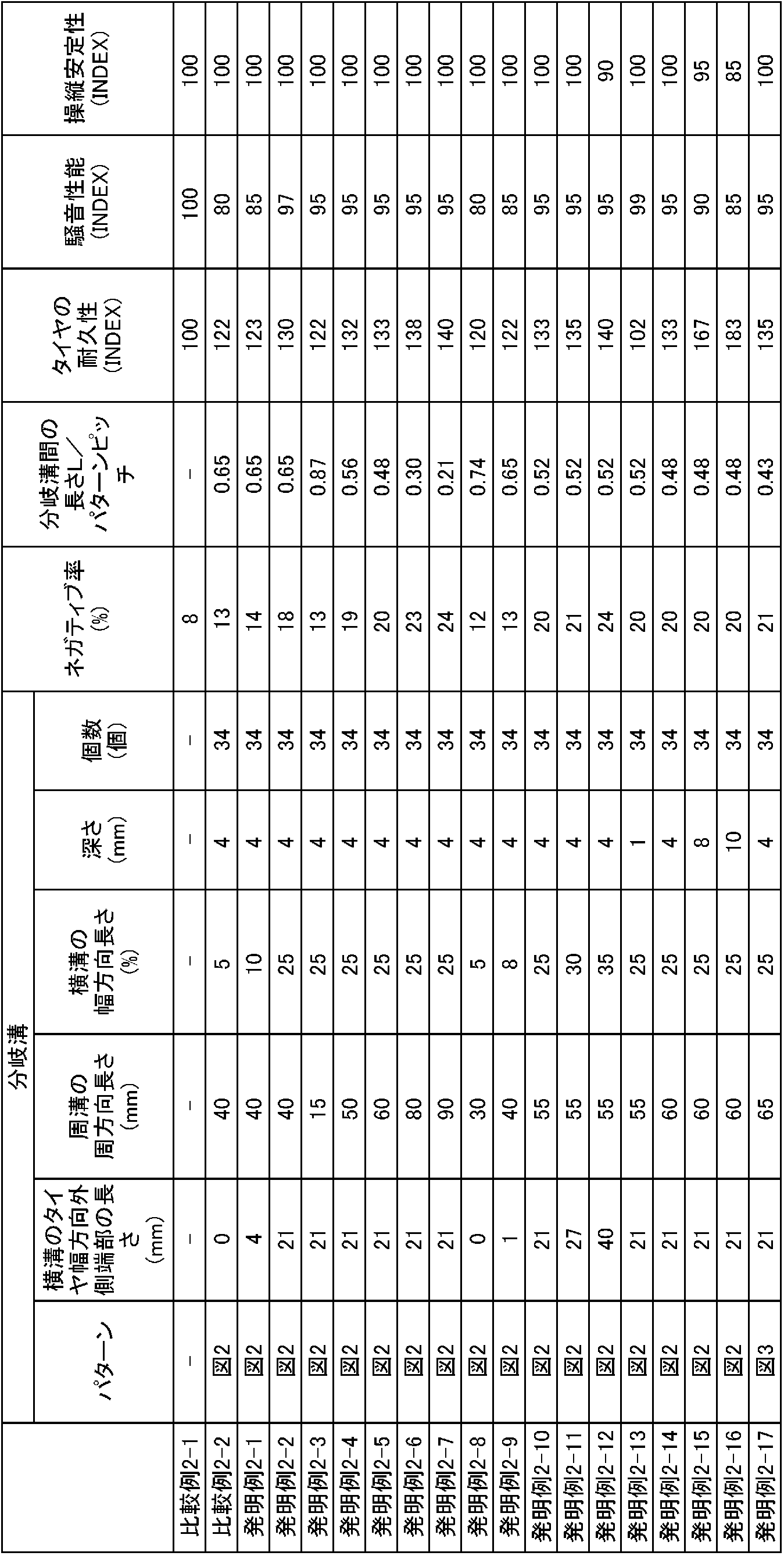
表2の結果は、比較例タイヤ2-1の各結果を100として指数表示した。指数が大きいほど性能に優れていることを示している。
3:傾斜ベルト、 3a,3b:傾斜ベルト層、 5:カーカス、 6:トレッド踏面、 7:適用リム、 21:周方向溝、 31:幅方向溝、 41:小穴、 21a,22b:ラグ溝、 51:周溝 52、52a、52b:横溝 54:ラグ溝 54a、54b、54c:溝部 Br:分岐溝 61:周溝 62、62a、62b、62c:横溝 64:ラグ溝 64a、64b、64c:溝部 6Br:分岐溝 A:中間領域、 CL:タイヤ赤道面、 L:凹部間のタイヤ周方向間隔、 TE:トレッド端
Claims (12)
- タイヤを適用リムに装着し、規定内圧を充填し、無負荷とした基準状態において、
タイヤ赤道面からトレッド端側へ、トレッド踏面のペリフェリに沿って該トレッド踏面のペリフェリ長の半幅の50%離間した、トレッド踏面のタイヤ幅方向位置と、同じく82%離間した、トレッド踏面のタイヤ幅方向位置とで挟まれたトレッド踏面における、タイヤ幅方向領域を中間領域としたとき、
タイヤ半部のそれぞれにおける該中間領域に、凹部をタイヤ周方向に沿って断続的に具え、
当該中間領域におけるネガティブ率が15%以上45%以下であること、を特徴とする自動二輪車用空気入りタイヤ。 - 前記凹部がタイヤ周方向に延びる周方向溝を含む、請求項1に記載の自動二輪車用空気入りタイヤ。
- タイヤ周方向に隣接する前記周方向溝のタイヤ周方向の間隔を、タイヤ周方向のパターンピッチ長さで除した値が0.15以上0.5以下である、請求項2に記載の自動二輪車用空気入りタイヤ。
- 前記凹部がタイヤ幅方向に延びる幅方向溝を含む、請求項1に記載の自動二輪車用空気入りタイヤ。
- タイヤ周方向に隣接する前記幅方向溝のタイヤ周方向の間隔を、タイヤ周方向のパターンピッチ長さで除した値が0.15以上0.5以下である、請求項4に記載の自動二輪車用空気入りタイヤ。
- 前記凹部が小穴を含む、請求項1に記載の自動二輪車用空気入りタイヤ。
- タイヤ周方向に隣接する前記小穴のタイヤ周方向の間隔を、タイヤ周方向のパターンピッチ長さで除した値が0.15以上0.5以下である、請求項6に記載の自動二輪車用空気入りタイヤ。
- 前記凹部は、タイヤ周方向に対して30°以下の角度で傾斜して延びる周方向溝部分を前記中間領域内に備えた、少なくとも1本の周溝と、タイヤ幅方向に対して30°以下の角度で傾斜して延びる横溝部分を前記中間領域内に備えて、該中間領域内で前記周溝に連通する、少なくとも1本の横溝と、からなる分岐溝であり、
前記分岐溝は、タイヤ半部のそれぞれにおいて、タイヤ周方向に沿って断続的に形成されており、
前記横溝の少なくとも1本は、前記中間領域のタイヤ幅方向外側端よりもタイヤ幅方向外側まで延在している、請求項1に記載の自動二輪車用空気入りタイヤ。 - 前記横溝のタイヤ幅方向長さが、前記トレッド踏面のペリフェリ長の半幅の8%以上30%以下である、請求項8に記載の自動二輪車用空気入りタイヤ。
- 前記周溝のタイヤ周方向長さが、20mm以上80mm以下である、請求項8または9に記載の自動二輪車用空気入りタイヤ。
- タイヤ周方向に隣接する前記分岐溝間の間隔を、タイヤ周方向のパターンピッチ長さで除した値が、0.15以上0.8以下である、請求項8~10のいずれか一項に記載の自動二輪車用空気入りタイヤ。
- タイヤ赤道面からトレッド端側へ、前記トレッド踏面のペリフェリに沿って該トレッド踏面のペリフェリ長の半幅の50%離間した、トレッド踏面のタイヤ幅方向位置と、前記トレッド端と、で挟まれた、トレッド踏面におけるタイヤ幅方向領域のネガティブ率が、15%以上35%以下である、請求項8~11のいずれか一項に記載の自動二輪車用空気入りタイヤ。
Priority Applications (3)
| Application Number | Priority Date | Filing Date | Title |
|---|---|---|---|
| CN201680045120.0A CN107848342B (zh) | 2015-07-31 | 2016-07-25 | 机动两轮车用充气轮胎 |
| EP16832489.5A EP3330102B1 (en) | 2015-07-31 | 2016-07-25 | Pneumatic tire for motorcycles |
| US15/744,196 US20180201069A1 (en) | 2015-07-31 | 2016-07-25 | Motorcycle pneumatic tire |
Applications Claiming Priority (4)
| Application Number | Priority Date | Filing Date | Title |
|---|---|---|---|
| JP2015152751A JP6719874B2 (ja) | 2015-07-31 | 2015-07-31 | 自動二輪車用空気入りタイヤ |
| JP2015-152751 | 2015-07-31 | ||
| JP2015152742A JP6710025B2 (ja) | 2015-07-31 | 2015-07-31 | 自動二輪車用空気入りタイヤ |
| JP2015-152742 | 2015-07-31 |
Publications (1)
| Publication Number | Publication Date |
|---|---|
| WO2017022206A1 true WO2017022206A1 (ja) | 2017-02-09 |
Family
ID=57942760
Family Applications (1)
| Application Number | Title | Priority Date | Filing Date |
|---|---|---|---|
| PCT/JP2016/003452 WO2017022206A1 (ja) | 2015-07-31 | 2016-07-25 | 自動二輪車用空気入りタイヤ |
Country Status (4)
| Country | Link |
|---|---|
| US (1) | US20180201069A1 (ja) |
| EP (1) | EP3330102B1 (ja) |
| CN (1) | CN107848342B (ja) |
| WO (1) | WO2017022206A1 (ja) |
Families Citing this family (2)
| Publication number | Priority date | Publication date | Assignee | Title |
|---|---|---|---|---|
| USD905619S1 (en) | 2019-12-04 | 2020-12-22 | Sumitomo Rubber Industries, Ltd. | Tire for motorcycle |
| USD918826S1 (en) | 2019-12-04 | 2021-05-11 | Sumitomo Rubber Industries, Ltd. | Tire for motorcycle |
Citations (6)
| Publication number | Priority date | Publication date | Assignee | Title |
|---|---|---|---|---|
| JPS63212105A (ja) * | 1987-02-27 | 1988-09-05 | Bridgestone Corp | 二輪車用空気入りタイヤ |
| JPH11192814A (ja) * | 1998-01-07 | 1999-07-21 | Bridgestone Corp | 二輪車用空気入りラジアルタイヤ |
| JP2007283803A (ja) * | 2006-04-12 | 2007-11-01 | Bridgestone Corp | 二輪車用空気入りタイヤ |
| JP2012176680A (ja) * | 2011-02-25 | 2012-09-13 | Sumitomo Rubber Ind Ltd | 自動二輪車用タイヤ |
| JP2014080109A (ja) * | 2012-10-16 | 2014-05-08 | Sumitomo Rubber Ind Ltd | 自動二輪車用タイヤ |
| JP2014205395A (ja) * | 2013-04-11 | 2014-10-30 | 住友ゴム工業株式会社 | 自動二輪車用タイヤ |
Family Cites Families (20)
| Publication number | Priority date | Publication date | Assignee | Title |
|---|---|---|---|---|
| JPS602202B2 (ja) * | 1980-06-13 | 1985-01-19 | 横浜ゴム株式会社 | 二輪自動車用タイヤ |
| CA2036807A1 (en) * | 1991-02-21 | 1992-08-22 | Wolfgang Bende | Motorcycle tire having curved, swept-back profiled tread grooves |
| JPH05201207A (ja) * | 1992-01-27 | 1993-08-10 | Bridgestone Corp | モーターサイクル用空気入りタイヤ |
| ES2221121T3 (es) * | 1997-02-27 | 2004-12-16 | Bridgestone Corporation | Cubierta neumatica para vehiculo de dos ruedas. |
| EP0928707B1 (en) * | 1998-01-07 | 2003-05-14 | Bridgestone Corporation | Pneumatic radial tire for motorcycle |
| JP2001030719A (ja) * | 1999-07-23 | 2001-02-06 | Bridgestone Corp | 空気入りタイヤ |
| JP2005138807A (ja) * | 2003-11-10 | 2005-06-02 | Sumitomo Rubber Ind Ltd | 自動二輪車の後輪用タイヤ |
| USD531569S1 (en) * | 2004-07-09 | 2006-11-07 | Pirelli Pneumatici S.P.A. | Motorcycle tire |
| JP2006076520A (ja) * | 2004-09-13 | 2006-03-23 | Bridgestone Corp | 二輪車用後輪タイヤ |
| JP2006232025A (ja) * | 2005-02-23 | 2006-09-07 | Bridgestone Corp | スクーター用空気入りラジアルタイヤおよびスクーター |
| DE202006006113U1 (de) * | 2006-04-15 | 2006-06-14 | Festo Ag & Co. | Faltenbalganordnung |
| EP2155505B1 (en) * | 2007-04-13 | 2013-01-09 | Pirelli Tyre S.P.A. | Motorcycle tires to improve performance and wear resistance of motorcycle tires |
| BRPI0823307B1 (pt) * | 2008-12-24 | 2020-01-28 | Pirelli | pneu para veículos a motor, par de pneus para veículos a motor, e, método para indicação de possibilidade de usar veículo a motor com os pneus que alcançaram condições de uso ideais ao condutor de um veículo a motor |
| JP4685922B2 (ja) * | 2008-12-26 | 2011-05-18 | 住友ゴム工業株式会社 | 空気入りタイヤ |
| WO2011041859A1 (en) * | 2009-10-07 | 2011-04-14 | Pirelli Tyre S.P.A. | Motorcycle tyres |
| JP6081467B2 (ja) * | 2011-09-29 | 2017-02-15 | ピレリ・タイヤ・ソチエタ・ペル・アツィオーニ | 二輪車用タイヤ |
| JP5385997B2 (ja) * | 2012-02-03 | 2014-01-08 | 住友ゴム工業株式会社 | 自動二輪車用タイヤ |
| JP5444393B2 (ja) * | 2012-03-01 | 2014-03-19 | 住友ゴム工業株式会社 | 自動二輪車用タイヤ |
| US10071599B2 (en) * | 2013-09-24 | 2018-09-11 | Sumitomo Rubber Industries, Ltd. | Motorcycle tire |
| CN103991338B (zh) * | 2014-05-20 | 2016-06-29 | 厦门正新橡胶工业有限公司 | 竞速用摩托车充气轮胎 |
-
2016
- 2016-07-25 WO PCT/JP2016/003452 patent/WO2017022206A1/ja active Application Filing
- 2016-07-25 CN CN201680045120.0A patent/CN107848342B/zh active Active
- 2016-07-25 EP EP16832489.5A patent/EP3330102B1/en active Active
- 2016-07-25 US US15/744,196 patent/US20180201069A1/en not_active Abandoned
Patent Citations (6)
| Publication number | Priority date | Publication date | Assignee | Title |
|---|---|---|---|---|
| JPS63212105A (ja) * | 1987-02-27 | 1988-09-05 | Bridgestone Corp | 二輪車用空気入りタイヤ |
| JPH11192814A (ja) * | 1998-01-07 | 1999-07-21 | Bridgestone Corp | 二輪車用空気入りラジアルタイヤ |
| JP2007283803A (ja) * | 2006-04-12 | 2007-11-01 | Bridgestone Corp | 二輪車用空気入りタイヤ |
| JP2012176680A (ja) * | 2011-02-25 | 2012-09-13 | Sumitomo Rubber Ind Ltd | 自動二輪車用タイヤ |
| JP2014080109A (ja) * | 2012-10-16 | 2014-05-08 | Sumitomo Rubber Ind Ltd | 自動二輪車用タイヤ |
| JP2014205395A (ja) * | 2013-04-11 | 2014-10-30 | 住友ゴム工業株式会社 | 自動二輪車用タイヤ |
Also Published As
| Publication number | Publication date |
|---|---|
| EP3330102A4 (en) | 2018-08-01 |
| CN107848342B (zh) | 2020-07-24 |
| CN107848342A (zh) | 2018-03-27 |
| US20180201069A1 (en) | 2018-07-19 |
| EP3330102B1 (en) | 2019-12-18 |
| EP3330102A1 (en) | 2018-06-06 |
Similar Documents
| Publication | Publication Date | Title |
|---|---|---|
| JP5667614B2 (ja) | 空気入りタイヤ | |
| JP6436080B2 (ja) | 空気入りタイヤ | |
| WO2013137193A1 (ja) | 空気入りタイヤ | |
| JP5590927B2 (ja) | 自動二輪車用空気入りタイヤ | |
| JP6559497B2 (ja) | 空気入りタイヤ | |
| JP6375850B2 (ja) | 空気入りタイヤ | |
| JP2012162160A (ja) | 自動二輪車用空気入りタイヤ | |
| JP5965138B2 (ja) | 自動二輪車用空気入りタイヤ | |
| JP2009280009A (ja) | 重荷重用タイヤ | |
| WO2017022206A1 (ja) | 自動二輪車用空気入りタイヤ | |
| JP6498560B2 (ja) | 自動二輪車用タイヤ | |
| JP6506061B2 (ja) | 自動二輪車用タイヤ | |
| WO2016093069A1 (ja) | 空気入りタイヤ | |
| JP2018043553A (ja) | 空気入りタイヤ | |
| JPWO2019189048A1 (ja) | 空気入りタイヤ | |
| JP6060217B2 (ja) | 自動二輪車用空気入りタイヤ | |
| WO2020179137A1 (ja) | 二輪車用タイヤ | |
| JP5201961B2 (ja) | 自動二輪車用空気入りタイヤ | |
| JP6710025B2 (ja) | 自動二輪車用空気入りタイヤ | |
| JP6350002B2 (ja) | 空気入りタイヤ | |
| JP6506060B2 (ja) | 自動二輪車用タイヤ | |
| JP6719874B2 (ja) | 自動二輪車用空気入りタイヤ | |
| US20220402308A1 (en) | Tire and tire-vehicle combination | |
| JP7131111B2 (ja) | 空気入りタイヤ | |
| JP2017081423A (ja) | 空気入りタイヤ |
Legal Events
| Date | Code | Title | Description |
|---|---|---|---|
| 121 | Ep: the epo has been informed by wipo that ep was designated in this application |
Ref document number: 16832489 Country of ref document: EP Kind code of ref document: A1 |
|
| WWE | Wipo information: entry into national phase |
Ref document number: 15744196 Country of ref document: US |
|
| NENP | Non-entry into the national phase |
Ref country code: DE |