WO2017006892A1 - ガスセンサのポンプ電極及び基準電極 - Google Patents
ガスセンサのポンプ電極及び基準電極 Download PDFInfo
- Publication number
- WO2017006892A1 WO2017006892A1 PCT/JP2016/069745 JP2016069745W WO2017006892A1 WO 2017006892 A1 WO2017006892 A1 WO 2017006892A1 JP 2016069745 W JP2016069745 W JP 2016069745W WO 2017006892 A1 WO2017006892 A1 WO 2017006892A1
- Authority
- WO
- WIPO (PCT)
- Prior art keywords
- solid electrolyte
- region
- electrode
- reference electrode
- gas
- Prior art date
- Legal status (The legal status is an assumption and is not a legal conclusion. Google has not performed a legal analysis and makes no representation as to the accuracy of the status listed.)
- Ceased
Links
Images





Classifications
-
- G—PHYSICS
- G01—MEASURING; TESTING
- G01N—INVESTIGATING OR ANALYSING MATERIALS BY DETERMINING THEIR CHEMICAL OR PHYSICAL PROPERTIES
- G01N27/00—Investigating or analysing materials by the use of electric, electrochemical, or magnetic means
- G01N27/26—Investigating or analysing materials by the use of electric, electrochemical, or magnetic means by investigating electrochemical variables; by using electrolysis or electrophoresis
- G01N27/403—Cells and electrode assemblies
- G01N27/406—Cells and probes with solid electrolytes
- G01N27/407—Cells and probes with solid electrolytes for investigating or analysing gases
- G01N27/41—Oxygen pumping cells
-
- G—PHYSICS
- G01—MEASURING; TESTING
- G01N—INVESTIGATING OR ANALYSING MATERIALS BY DETERMINING THEIR CHEMICAL OR PHYSICAL PROPERTIES
- G01N27/00—Investigating or analysing materials by the use of electric, electrochemical, or magnetic means
- G01N27/26—Investigating or analysing materials by the use of electric, electrochemical, or magnetic means by investigating electrochemical variables; by using electrolysis or electrophoresis
- G01N27/403—Cells and electrode assemblies
- G01N27/406—Cells and probes with solid electrolytes
- G01N27/407—Cells and probes with solid electrolytes for investigating or analysing gases
- G01N27/4075—Composition or fabrication of the electrodes and coatings thereon, e.g. catalysts
-
- G—PHYSICS
- G01—MEASURING; TESTING
- G01N—INVESTIGATING OR ANALYSING MATERIALS BY DETERMINING THEIR CHEMICAL OR PHYSICAL PROPERTIES
- G01N27/00—Investigating or analysing materials by the use of electric, electrochemical, or magnetic means
- G01N27/26—Investigating or analysing materials by the use of electric, electrochemical, or magnetic means by investigating electrochemical variables; by using electrolysis or electrophoresis
- G01N27/403—Cells and electrode assemblies
- G01N27/406—Cells and probes with solid electrolytes
- G01N27/407—Cells and probes with solid electrolytes for investigating or analysing gases
- G01N27/4073—Composition or fabrication of the solid electrolyte
- G01N27/4074—Composition or fabrication of the solid electrolyte for detection of gases other than oxygen
-
- G—PHYSICS
- G01—MEASURING; TESTING
- G01N—INVESTIGATING OR ANALYSING MATERIALS BY DETERMINING THEIR CHEMICAL OR PHYSICAL PROPERTIES
- G01N27/00—Investigating or analysing materials by the use of electric, electrochemical, or magnetic means
- G01N27/26—Investigating or analysing materials by the use of electric, electrochemical, or magnetic means by investigating electrochemical variables; by using electrolysis or electrophoresis
- G01N27/403—Cells and electrode assemblies
- G01N27/406—Cells and probes with solid electrolytes
- G01N27/407—Cells and probes with solid electrolytes for investigating or analysing gases
- G01N27/409—Oxygen concentration cells
-
- G—PHYSICS
- G01—MEASURING; TESTING
- G01N—INVESTIGATING OR ANALYSING MATERIALS BY DETERMINING THEIR CHEMICAL OR PHYSICAL PROPERTIES
- G01N27/00—Investigating or analysing materials by the use of electric, electrochemical, or magnetic means
- G01N27/26—Investigating or analysing materials by the use of electric, electrochemical, or magnetic means by investigating electrochemical variables; by using electrolysis or electrophoresis
- G01N27/416—Systems
- G01N27/417—Systems using cells, i.e. more than one cell and probes with solid electrolytes
- G01N27/419—Measuring voltages or currents with a combination of oxygen pumping cells and oxygen concentration cells
Definitions
- the present invention relates to a pump electrode and a reference electrode provided on the surface of a solid electrolyte body in a gas sensor.
- the gas sensor is arranged in the exhaust system of the internal combustion engine, and is used to measure the concentration of a specific gas such as NOx (nitrogen oxide) in the measurement gas using the exhaust gas flowing through the exhaust system as the measurement gas.
- the gas sensor has a gas sensor element, and the gas sensor element applies a paste-like electrode material containing a noble metal and a solid electrolyte to the surface of the ceramic sheet constituting the solid electrolyte body, and fires the electrode material and the ceramic sheet. It is manufactured by.
- a gas to be measured comes into contact with a three-phase interface composed of a noble metal and a solid electrolyte, and oxygen ions are conducted there.
- the oxygen decomposition activity capability in the gas sensor depends on how effectively the noble metal, the solid electrolyte and the gas to be measured are contacted. The size of will be affected.
- the electrode of the gas sensor described in Patent Document 1 has, in its cross section, a noble metal region made of a noble metal, a solid electrolyte region made of a solid electrolyte, and a mixed region in which a noble metal and a solid electrolyte are mixed. ing. And, by forming a mixed region along the boundary between the noble metal region and the solid electrolyte region and making it exist, the ionization efficiency of oxygen molecules contained in the gas to be measured is increased, and a stable sensor output can be obtained. Become.
- the gas sensor disclosed in Patent Document 1 has a problem that the mixed region of the noble metal and the solid electrolyte is formed only at the boundary between the noble metal region and the solid electrolyte region, and the distribution of the mixed region is not sufficient. . Further, in order to increase the three-phase interface between the noble metal, the solid electrolyte, and the gas to be measured, it is necessary to appropriately form pores through which the gas to be measured can flow.
- the gas sensor disclosed in Patent Document 1 has a problem that the structure is not sufficient to increase the oxygen decomposition activity of the electrode by increasing the three-phase interface because pores are not sufficiently formed.
- the present invention has been made in order to solve the above-described conventional problems, and is effective in an appropriate ratio between the mixed region where the noble metal and the solid electrolyte are mixed and the pores into which the measurement gas or the reference gas flows.
- a pump electrode and a reference electrode of a gas sensor having a structure formed in the above and capable of effectively increasing the oxygen decomposition activity are provided.
- standard electrode is provided.
- a solid electrolyte body having oxygen ion conductivity is provided on a gas side surface exposed to a gas to be measured, and the solid electrolyte body is formed by using oxygen in the gas to be measured as oxygen ions when energized. It is a pump electrode of a gas sensor for passing and discharging to a reference side surface opposite to the gas side surface.
- the pump electrode contains a Pt—Au alloy and a solid electrolyte made of the same ceramic material as that of the ceramic material constituting the solid electrolyte body.
- the noble metal region in which the Pt—Au alloy is gathered in a lump the solid electrolyte region in which the solid electrolyte is gathered in a lump, the Pt—Au alloy and the above
- the mixed region in the cut surface occupies a range of 30 to 90% of the entire portion excluding the pores, and the pores are formed adjacent to the mixed region. It is a feature.
- Another aspect of the present invention is provided on a reference side surface exposed to a reference gas in a solid electrolyte body having oxygen ion conductivity, and is exposed to a gas side surface opposite to the reference side surface when energized. It is a reference electrode of a gas sensor for passing oxygen in a gas to be measured as oxygen ions through the solid electrolyte body and discharging it to the reference side surface.
- the reference electrode contains Pt and a solid electrolyte made of the same ceramic material as that of the ceramic material constituting the solid electrolyte body.
- the noble metal region in which the Pt is collected in a lump On the cut surface obtained by cutting the reference electrode along the thickness direction, the noble metal region in which the Pt is collected in a lump, the solid electrolyte region in which the solid electrolyte is collected in a lump, and the Pt and the solid electrolyte are distributed. There are mixed regions and pores. Further, the mixed region in the reference electrode occupies a range of 30 to 90% of the entire portion excluding the pores in the cut surface obtained by cutting the reference electrode along the thickness direction. It is formed adjacent to the mixed region.
- a noble metal region, a solid electrolyte region, a mixed region, and pores exist on a cut surface obtained by cutting the pump electrode along the thickness direction.
- the mixed region occupies a range of 30 to 90% of the entire portion excluding pores on the cut surface. As a result, the mixed region is distributed over a wide range of the pump electrode, whereby the portion where the mixed region and the gas to be measured contact can be increased.
- pores are formed adjacent to the mixed region on the cut surface of the pump electrode.
- the gas to be measured flowing into the pores can come into contact with the mixed region, and the three-phase interface between the noble metal and the solid electrolyte and the gas to be measured in the mixed region can be effectively increased. Therefore, according to the pump electrode of the gas sensor, the mixed region where the noble metal and the solid electrolyte are mixed and the pores into which the gas to be measured flows are effectively formed at an appropriate ratio, and the oxygen decomposition activity is improved. Can be effectively increased.
- the mixed region is distributed over a wide range of the reference electrode, and the portion where the mixed region and the reference gas are in contact is increased. be able to. Further, pores are formed adjacent to the mixed region in the cut surface of the reference electrode. Thereby, the reference gas flowing into the pores can come into contact with the mixed region, and the three-phase interface between the noble metal and the solid electrolyte and the reference gas in the mixed region can be effectively increased. Therefore, according to the reference electrode of the gas sensor, the mixed region in which the noble metal and the solid electrolyte are mixed and the pores into which the reference gas flows are effectively formed at an appropriate ratio, and thereby the oxygen decomposition activity. Can be effectively increased.
- the pump electrode of the gas sensor which is one embodiment of the present invention and the reference electrode of the gas sensor which is another embodiment of the present invention can be formed in the same gas sensor.
- the mixed region may be formed from the boundary position to the surface position in the pump electrode in the whole excluding the noble metal region, the solid electrolyte region, or the portion where the pores are formed.
- the whole part excluding pores means the whole noble metal region, solid electrolyte region, and mixed region. And the part which is not a noble metal area
- Mated region refers to a region that is not a noble metal region or a solid electrolyte region, and includes both a Pt—Au alloy and a solid electrolyte, in the entire portion excluding pores, on the cut surface of the pump electrode.
- the Pt—Au alloy and the solid electrolyte enter into each other three-dimensionally and come into contact with each other in a complicated manner.
- the phase of the Pt—Au alloy and the phase of the solid electrolyte are intricately intertwined in a marbling manner.
- the Pt—Au alloy and the solid electrolyte in the mixed region is a continuous phase with the Pt—Au alloy in the noble metal region, the solid electrolyte in the solid electrolyte region, or the solid electrolyte body.
- the mixed region is a region where there are a plurality of boundary lines separating the Pt—Au alloy and the solid electrolyte.
- the region where there are multiple boundary lines separating the Pt—Au alloy and the solid electrolyte means that there are two or more boundary lines separating the Pt—Au alloy and the solid electrolyte within the 0.5 ⁇ m square in the mixed region. Refers to the area to be.
- the region where there are a plurality of boundary lines separating the Pt—Au alloy and the solid electrolyte means that the Pt—Au alloy and the solid electrolyte are not divided into two by only one continuous curve.
- the range of 0.5 ⁇ m square may be within the range of 0.1 ⁇ m 2 of an arbitrary shape in consideration of the case where it is difficult to draw the shape of the mixed region.
- the mixed region may be formed from the boundary position to the surface position in the reference electrode in the whole except the noble metal region, the solid electrolyte region, or the portion where the pores are formed.
- the formation range of the mixed region in the entire portion excluding the pores is less than 30% on the cut surface of the reference electrode, the mixed region is not sufficiently formed, and the oxygen decomposition activity cannot be sufficiently exhibited.
- the whole part excluding pores means the whole noble metal region, solid electrolyte region, and mixed region. And the part which is not a noble metal area
- Mated region refers to a region that is not a noble metal region or a solid electrolyte region and includes both Pt and a solid electrolyte in the entire portion excluding pores on the cut surface of the reference electrode.
- Pt and the solid electrolyte enter into each other three-dimensionally and come into contact with each other in a complicated manner.
- the Pt phase and the solid electrolyte phase are intertwined in a marbling manner.
- at least a part of Pt and the solid electrolyte in the mixed region is a continuous phase with Pt in the noble metal region, the solid electrolyte in the solid electrolyte region, or the solid electrolyte body.
- the mixed region is a region where there are a plurality of boundary lines separating Pt and the solid electrolyte.
- the region where there are a plurality of boundary lines separating Pt and solid electrolyte refers to a region where two or more boundary lines separating Pt and solid electrolyte exist within a 0.5 ⁇ m square within the mixed region. .
- the region where there are a plurality of boundary lines separating Pt and solid electrolyte means that the region is not divided into Pt and solid electrolyte by only one continuous curve.
- the range of 0.5 ⁇ m square may be within the range of 0.1 ⁇ m 2 of an arbitrary shape in consideration of the case where it is difficult to draw the shape of the mixed region.
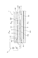
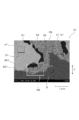
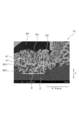
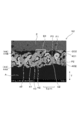
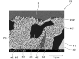
- FIG. 1 It is a section explanatory view showing a gas sensor element which has a pump electrode and a reference electrode concerning an embodiment of the invention in this application. It is a figure which shows the gas sensor element which has the pump electrode and reference electrode which concern on embodiment of this invention, and is the II-II sectional explanatory drawing of FIG. It is a SEM photograph which shows the cut surface of the pump electrode which concerns on embodiment of this invention. It is a SEM photograph which expands and shows a part of FIG. It is a SEM photograph which expands and shows a part of FIG. It is a SEM photograph which shows the other cut surface of the pump electrode which concerns on embodiment of this invention. It is a SEM photograph which shows the cut surface of the reference electrode which concerns on embodiment of this invention.
- the pump electrode 3 of the gas sensor according to the present embodiment is formed on the gas side surface 201 exposed to the measurement gas G in the solid electrolyte body 2 having oxygen ion conductivity.
- the pump electrode 3 is used to pass the oxygen in the gas G to be measured through the solid electrolyte body 2 as oxygen ions and discharge it to the reference side surface 202 opposite to the gas side surface 201 by energization.
- the pump electrode 3 contains a Pt—Au alloy and a solid electrolyte made of the same ceramic material as the ceramic material constituting the solid electrolyte body 2.
- the mixed region 33 occupies a range of 30 to 90% of the entire area of the cut surface (cut surface of the pump electrode) X1 excluding the pores 34.
- the pores 34 are formed adjacent to the mixed region 33.
- the Pt—Au alloy is indicated by a1
- the solid electrolyte is indicated by b1.
- the reference electrode 4 according to the present embodiment is provided on the reference side surface 202 exposed to the reference gas A in the solid electrolyte body 2 having oxygen ion conductivity.
- oxygen in the measurement gas G exposed to the gas side surface 201 opposite to the reference side surface 202 passes through the solid electrolyte body 2 as oxygen ions and is discharged to the reference side surface 202. Used to do.
- the reference electrode 4 contains Pt and a solid electrolyte made of the same ceramic material as the ceramic material constituting the solid electrolyte body 2.
- a noble metal region in which Pt gathers in a lump shape. 41, a solid electrolyte region (second solid electrolyte region) 42 in which solid electrolytes are gathered in a lump, a mixed region (second mixed region) 43 in which Pt and the solid electrolyte are distributed mottled, and pores (second 44). At least a part of the mixed region 43 is distributed from the boundary position (second boundary position) 401 adjacent to the reference-side surface 202 of the solid electrolyte body 2 in the reference electrode 4 to the surface position 402 of the reference electrode 4. .
- the mixed region 43 occupies a range of 30 to 90% in the entire area of the section excluding the pores 44 in the cut surface X2.
- the pores 44 are formed adjacent to the mixed region 43.
- the Pt—Au alloy is indicated by a2 and the solid electrolyte is indicated by b2.
- the gas sensor is disposed in the exhaust system of the internal combustion engine, and measures the concentration of NOx (nitrogen oxide) as a specific gas in the gas G to be measured, using the exhaust gas flowing through the exhaust system as the gas G to be measured.
- the gas sensor element 1 constituting the gas sensor is formed in an elongated shape, and the gas sensor element 1 is attached to the housing via an insulator.
- the tip side portion of the gas sensor element 1 protruding from the insulator is covered with a cover provided with a hole through which the gas G to be measured passes.
- the solid electrolyte body 2 is formed in a flat plate shape, and a measured gas chamber 101 into which the measured gas G is introduced is formed on the gas side surface 201 of the solid electrolyte body 2.
- a measured gas chamber 101 into which the measured gas G is introduced is formed on the gas side surface 201 of the solid electrolyte body 2.
- An insulating first spacer 62 is stacked around the gas side surface 201 of the solid electrolyte body 2, and an insulating counter plate 61 is stacked on the first spacer 62.
- the gas chamber 101 to be measured is formed by being surrounded by the solid electrolyte body 2, the first spacer 62, and the counter plate 61.
- a porous body 621 for introducing the measurement gas G under a predetermined diffusion resistance is embedded in the tip side portion of the first spacer 62.
- a reference gas chamber 102 into which air is introduced as the reference gas A is formed on the reference side surface 202 of the solid electrolyte body 2 opposite to the gas side surface 201.
- An insulating second spacer 64 is laminated around the reference surface 202 of the solid electrolyte body 2, and an insulating heater substrate 63 is laminated on the second spacer 64.
- a heater 631 that generates heat when energized is embedded in the heater substrate 63.
- the reference gas chamber 102 is surrounded by the solid electrolyte body 2, the second spacer 64, and the heater substrate 63.
- the reference gas A is introduced into the reference gas chamber 102 from the proximal end side of the second spacer 64.
- the pump electrode 3 is disposed at a position close to the porous body 621 in the tip side portion of the gas-side surface 201 of the solid electrolyte body 2.
- the reference electrode 4 is a tip side portion of the reference side surface 202 of the solid electrolyte body 2 and is disposed on the back side of the position where the pump electrode 3 is disposed.
- a predetermined voltage is applied between the pump electrode 3 and the reference electrode 4 by the voltage applying means 71.
- oxygen molecules in the gas G to be measured in the gas chamber 101 to be measured are oxygen ions at the three-phase interface between the Pt—Au alloy and the solid electrolyte on the surface of the pump electrode 3.
- the oxygen ions pass through the solid electrolyte body 2.
- the oxygen ions exchange electrons at the three-phase interface between Pt and the solid electrolyte on the surface of the reference electrode 4, and become oxygen molecules again. Thereby, oxygen molecules in the measured gas chamber 101 are exhausted to the reference gas chamber 102.
- the position on the gas-side surface 201 of the solid electrolyte body 2 on the base end side (downstream of the flow of the gas G to be measured) from the position where the pump electrode 3 is arranged is
- the sensor electrode 51 and the monitor electrode 52 are arranged side by side.
- the sensor electrode 51 is an electrode having activity with respect to NOx and oxygen, and is used to detect the NOx concentration in the measurement gas G after the oxygen concentration is adjusted by the pump electrode 3.
- the monitor electrode 52 is an electrode having activity against oxygen, and is used to detect the (residual) oxygen concentration in the gas G to be measured after the oxygen concentration is adjusted by the pump electrode 3.
- the reference electrode 4 is arranged on the reference side surface 202 of the solid electrolyte body 2 on the back side of the position where the pump electrode 3, the sensor electrode 51, and the monitor electrode 52 are provided. Only one reference electrode 4 can be provided for the entire position where the pump electrode 3, the sensor electrode 51, and the monitor electrode 52 are provided. In addition, the reference electrode 4 can be provided separately for each of the pump electrode 3, the sensor electrode 51, and the monitor electrode 52.
- the solid electrolyte body 2, the solid electrolyte in the pump electrode 3, and the solid electrolyte in the reference electrode 4 are made of yttria stabilized zirconia.
- the counter plate 61, the first spacer 62, the heater substrate 63, and the second spacer 64 are made of alumina.
- a predetermined voltage for expressing the limit current characteristic is applied between the sensor electrode 51 and the reference electrode 4, and the sensor electrode 51 and the reference electrode are detected by the sensor current detection unit 72.
- an oxygen ion current flowing through the solid electrolyte body 2 is detected.
- a predetermined voltage for expressing the limit current characteristic is applied between the monitor electrode 52 and the reference electrode 4, and the monitor current detection means 73 causes a solid between the monitor electrode 52 and the reference electrode 4.
- An oxygen ion current flowing through the electrolyte body 2 is detected.
- the sensor current detection means 72 detects the oxygen ion current when decomposing NOx and residual oxygen, while the monitor current detection means 73 detects the oxygen ion current when decomposing residual oxygen. Then, by subtracting the value of the oxygen ion current in the monitor current detection means 73 from the value of the oxygen ion current in the sensor current detection means 72, the NOx concentration in the measured gas G can be detected.
- the proportion of Pt is 99 mass% and the proportion of Au (gold) is 1 mass%. Further, in the entire Pt—Au alloy, the proportion of Pt can be 95 to 99.9 mass%, and the proportion of Au can be 0.1 to 5 mass%.
- FIG. 3 to 5 show photographs of the cut surface X1 of the pump electrode 3 cut along the thickness direction T of the gas sensor element 1.
- FIG. 3 These photographs were taken with a scanning electron microscope (SEM). As the scanning electron microscope, model number S5500 manufactured by Hitachi High-Technologies Corporation was used. The SEM photograph shown in FIG. 3 was taken at a magnification of 10,000 times.
- FIG. 4 is an SEM photograph (magnification of 30,000 times) of a part R1 of FIG. 3
- FIG. 5 is an SEM photograph of part R2 of FIG. 4 (magnification 100,000 times).
- the mixed region 33 of the Pt—Au alloy (a1) and the solid electrolyte (b1) is distributed over substantially the entire pump electrode 3.
- the mixed region 33 is formed from the boundary position 301 to the surface position 302 in the reference electrode 4 in the whole except for the portion where the noble metal region 31, the solid electrolyte region 32 or the pores 34 are formed.
- the mixed region 33 is formed as a portion where there are a plurality of boundary lines E separating the Pt—Au alloy and the solid electrolyte within a 0.5 ⁇ m square range P3 (see the SEM photograph shown in FIG. 5).
- the Pt—Au alloy and the solid electrolyte enter into each other three-dimensionally and come into contact with each other in a complicated manner. Further, a part of the Pt—Au alloy in the mixed region 33 is in a continuous phase with the Pt—Au alloy in the noble metal region 31, and a part of the solid electrolyte in the mixed region 33 is a solid electrolyte.
- the solid electrolyte in the region 32 or the solid electrolyte body 2 is a continuous phase.
- FIG. 6 the SEM photograph of the cut surface X1 of the other site
- FIG. 7 and 8 show SEM photographs of the cut surface X2 of the reference electrode 4 cut along the thickness direction T of the gas sensor element 1.
- FIG. 7 and 8 show SEM photographs of the cut surface X2 of the reference electrode 4 cut along the thickness direction T of the gas sensor element 1.
- FIG. 7 and 8 show SEM photographs of the cut surface X2 of the reference electrode 4 cut along the thickness direction T of the gas sensor element 1.
- FIG. 7 and 8 were taken with a scanning electron microscope (SEM), and Hitachi High-Technologies Corporation (Hitachi High- Model number S5500 manufactured by Technologies Corporation) was used.
- the SEM photograph shown in FIG. 7 was taken at a magnification of 5,000 times.
- FIG. 8 is an enlarged SEM photograph (magnification of 30,000) of a part of FIG. As shown in FIGS.
- the mixed region 43 of Pt (a2) and the solid electrolyte (b2) is distributed over substantially the entire reference electrode 4 in the cut surface X2.
- the mixed region 43 is formed from the boundary position 401 to the surface position 402 in the reference electrode 4 in the whole except the portion where the noble metal region 41, the solid electrolyte region 42 or the pores 44 are formed.
- the mixed region 43 is formed as a portion where a plurality of boundary lines separating Pt and the solid electrolyte exist within a 0.5 ⁇ m square range P3. In the mixed region 43, Pt and the solid electrolyte enter into each other three-dimensionally and come into contact with each other in a complicated manner.
- a part of Pt in the mixed region 43 is a phase continuous with Pt in the noble metal region 41, and a part of the solid electrolyte in the mixed region 43 is a solid electrolyte in the solid electrolyte region 42. Or a continuous phase with the solid electrolyte body 2.
- a paste of electrode materials constituting each of the pump electrode 3, the reference electrode 4, the sensor electrode 51, and the monitor electrode 52 is applied to a solid electrolyte ceramic sheet, and the solid electrolyte sheet Form. Further, the solid electrolyte sheet, the counter plate 61, the first spacer 62, the heater substrate 63, and the second spacer 64 are laminated to form a laminated body, and the laminated body is fired in a state where pressure is applied in the lamination direction of the laminated body. To do. Thereafter, as the energization process, a predetermined voltage is applied between the pump electrode 3 and the reference electrode 4 for a predetermined time. This predetermined voltage can be set higher than the voltage applied between the pump electrode 3 and the reference electrode 4 when the gas sensor is used by the voltage applying means 71.
- the Pt—Au alloy in the noble metal region 31 of the pump electrode 3 penetrates into the solid electrolyte in the solid electrolyte region 32 of the pump electrode 3. Then, the energization process forms a mixed region 33 in which the Pt—Au alloy and the solid electrolyte are distributed in a mottled manner. As the Pt—Au alloy moves, the pores 34 are located in the vicinity where the Pt—Au alloy existed before the movement. Is thought to be formed. Thus, the mixed region 33 and the pores 34 are formed in the pump electrode 3 by performing the energization process. Accordingly, the range in which the noble metal region 31 and the solid electrolyte region 32 are formed becomes narrow.
- a mixed region 43 in which Pt and solid electrolyte are distributed in a mottled manner is formed, and with the movement of Pt, pores 44 are formed in the vicinity where Pt existed before the movement.
- the mixed region 43 and the pores 44 are formed in the reference electrode 4 by performing the energization process. Accordingly, the range in which the noble metal region 41 and the solid electrolyte region 42 are formed becomes narrow.
- the pores 34 in the pump electrode 3 may be formed by a burned material when a burned material is added to the paste of the electrode material constituting the pump electrode 3 and the paste is fired, instead of being formed by energization treatment. The same applies to the pores 44 in the reference electrode 4.
- the noble metal region 31 and the solid electrolyte region are near the boundary position 301 adjacent to the gas side surface 201 of the solid electrolyte body 2 on the cut surface X1 of the pump electrode 3.
- the mixed region 33 is most distributed. Most of the vicinity of the boundary position 301 of the pump electrode 3 is formed by the mixed region 33, and most of the pores 34 are formed at portions other than the vicinity of the boundary position 301.
- the noble metal region 31, the solid electrolyte region 32, and the pores 34 are formed in a distributed manner in portions other than the vicinity of the boundary position 301 of the pump electrode 3. Further, as shown in the SEM photograph of FIG.
- the noble metal region 41, the solid electrolyte region 42, and the mixture are present in the vicinity of the boundary position 401 adjacent to the reference surface 202 of the solid electrolyte body 2 on the cut surface X2 of the reference electrode 4.
- the pores 44 are distributed most frequently. Near the boundary position 401 of the reference electrode 4, many mixed regions 43 and pores 44 are formed.
- the precious metal region 31 is entirely formed of a Pt—Au alloy within a 0.5 ⁇ m square range P1 in the cut surface X1. It has a part.
- the solid electrolyte region 32 has a portion formed entirely by the solid electrolyte within a 0.5 ⁇ m square range P2 on the cut surface X1.
- the mixed region 33 is formed as a portion where a plurality of boundary lines E separating the Pt—Au alloy and the solid electrolyte exist in a 0.5 ⁇ m square range P3 on the cut surface X1. Note that the ranges P1 to P3 may be 2 ⁇ m square.
- the noble metal region 41 is a portion in which all of the 0.5 ⁇ m square range P1 in the cut surface X2 is formed of Pt.
- the solid electrolyte region 32 has a portion formed entirely by the solid electrolyte within a 0.5 ⁇ m square range P2 on the cut surface X2.
- the mixed region 33 is formed as a portion where a plurality of boundary lines separating Pt and the solid electrolyte exist within a 0.5 ⁇ m square range P3 on the cut surface X2.
- the ranges P1 to P3 can be 2 ⁇ m square, and can be a range of 0.1 ⁇ m 2 of any shape.
- the pore 34 has an open pore 34 ⁇ / b> A having an opening shape formed by being recessed from the surface of the pump electrode 3, There are formed closed pores 34B.
- the pores 34 are formed three-dimensionally continuously, and the independent pores 34B may be open pores 34A if the cut surfaces X1 are different.
- the pores 34 in the pump electrode 3 occupy 20 to 50% of the total volume of the pump electrode 3. In other words, the porosity of the entire pump electrode 3 is 20 to 50%.
- the surface position 302 of the pump electrode 3 is formed in a complicated uneven shape. There are many open pores 34A at the surface position 302 of the pump electrode 3, and the gas G to be measured can come into contact with the Pt—Au alloy and the solid electrolyte in the mixed region 33 through the open pores 34A.
- the pore 44 has an open pore 44 ⁇ / b> A having an opening shape that is depressed from the surface of the reference electrode 4, and the inside of the reference electrode 4.
- the pores 34 are formed three-dimensionally continuously, and the independent pores 44B may be open pores 44A if the cut surfaces X2 are different.
- the pores 44 in the reference electrode 4 occupy 20 to 60% of the total volume of the reference electrode 4. In other words, the porosity of the entire reference electrode 4 is 20 to 60%.
- the surface position 402 of the reference electrode 4 is formed in a complicated uneven shape. Many open pores 44A also exist on the surface position 402 of the reference electrode 4, and the reference gas A can come into contact with Pt and the solid electrolyte in the mixed region 43 via the open pores 44A.
- the pump electrode 3 of the gas sensor the noble metal region 31, the solid electrolyte region 32, the mixed region 33, and the pores 34 exist on the cut surface X ⁇ b> 1 obtained by cutting the pump electrode 3 along the thickness direction T.
- the mixed region 33 occupies a range of 30 to 90% of the entire portion excluding the pores 34 in the cut surface X1. Thereby, the mixed region 33 is distributed over a wide range of the pump electrode 3, and the portion where the mixed region 33 and the measurement gas G are in contact can be increased.
- the mixed region 33 is distributed from the boundary position 301 to the surface position 302 in the pump electrode 3. Thereby, the measurement gas G can come into contact with the mixed region 33 at any position in the thickness direction T of the pump electrode 3. Further, pores 34 are formed adjacent to the mixed region 33 in the cut surface X1 of the pump electrode 3. Thereby, the measurement gas G flowing into the pores 34 can come into contact with the mixed region 33, and the three-phase interface between the noble metal and the solid electrolyte and the measured gas G in the mixed region 33 can be effectively increased. .
- the noble metal region 41, the solid electrolyte region 42, the mixed region 43, and the pores 44 exist on the cut surface X ⁇ b> 2 obtained by cutting the reference electrode 4 along the thickness direction T.
- the mixed region 43 occupies a range of 30 to 90% of the entire portion excluding the pores 44 in the cut surface X2. Thereby, the mixed area
- the mixed region 43 is distributed from the boundary position 401 to the surface position 402 in the reference electrode 4.
- the reference gas A can come into contact with the mixed region 43 at any position in the thickness direction T of the reference electrode 4.
- pores 44 are formed adjacent to the mixed region 43 in the cut surface X ⁇ b> 2 of the reference electrode 4. Thereby, the reference gas A flowing into the pores 44 can come into contact with the mixed region 43, and the three-phase interface between the noble metal and solid electrolyte and the reference gas A in the mixed region 43 can be effectively increased.
- the mixed region 33 in which the noble metal and the solid electrolyte are mixed and the pores 34 into which the measurement gas G flows are effectively formed at an appropriate ratio. Is done.
- the mixed region 43 in which the noble metal and the solid electrolyte are mixed and the pores 44 into which the reference gas A flows are effectively formed at an appropriate ratio.
- the oxygen decomposition activity in the pump electrode 3 and the reference electrode 4 can be improved more effectively.
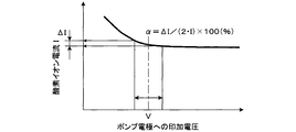
- the output current change rate ⁇ is detected when the voltage V applied between the pump electrode 3 and the reference electrode 4 varies according to the variation in oxygen decomposition capacity. This is shown as the rate of change of the oxygen ion current I detected by the current detector 72.
- This output current change rate ⁇ fluctuates due to fluctuations in the amount of residual oxygen in the measurement gas G from which oxygen has been exhausted by the pump electrode 3 and the reference electrode 4.
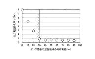
- FIG. 10 is a graph showing the relationship between the distribution range of the mixed region 33 in the pump electrode 3 (distribution range in the entire portion excluding the pores 34 in the cut surface X1) (%) and the output current change rate ⁇ (%). It is. As shown in the graph of FIG. 10, when the distribution range of the mixed region 33 in the pump electrode 3 is 30% or more, the output current change rate ⁇ is maintained at a small value. On the other hand, the output current change rate ⁇ tends to increase as the distribution range of the mixed region 33 in the pump electrode 3 decreases to less than 30%. Therefore, it was confirmed that the oxygen decomposition ability of the pump electrode 3 related to the output current change rate ⁇ can be improved by setting the distribution range of the mixed region 33 in the pump electrode 3 to 30% or more.
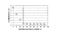
- FIG. 11 is a graph showing the relationship between the distribution range of the mixed region 43 in the reference electrode 4 (distribution range in the entire portion of the cut surface X2 excluding the pores 44) (%) and the output current change rate ⁇ (%). It is. As shown in the graph of FIG. 10, when the distribution range of the mixed region 43 in the reference electrode 4 is 30% or more, the output current change rate ⁇ is maintained at a small value. On the other hand, the output current change rate ⁇ tends to increase as the distribution range of the mixed region 43 in the reference electrode 4 decreases to less than 30%. Therefore, it was confirmed that the oxygen decomposition ability of the reference electrode 4 related to the output current change rate ⁇ can be improved by setting the distribution range of the mixed region 43 in the reference electrode 4 to 30% or more.
- FIG. 12 is a graph showing the relationship between the porosity of the pump electrode 3 (volume occupied by the pores 34 with respect to the entire pump electrode 3) (volume%) and the output current change rate ⁇ (%).
- the porosity of the pump electrode 3 was determined by observing each of a plurality of cut surfaces cut by a focused ion beam (FIB) device with a scanning electron microscope (SEM). This porosity was determined based on a three-dimensional structure analysis method called FIB-SEM method. As shown in the graph of FIG. 12, when the porosity of the pump electrode 3 is 20 to 50% by volume, the current change rate ⁇ is maintained at a small value.
- FIB focused ion beam
- the output current change rate ⁇ tends to increase. Further, as the porosity of the pump electrode 3 increases to exceed 50% by volume, the output current change rate ⁇ tends to increase. When the porosity exceeds 80% by volume, conduction failure occurs. Therefore, it was confirmed that the oxygen decomposition ability of the pump electrode 3 related to the output current change rate ⁇ can be improved by setting the porosity of the pump electrode 3 to 20 to 50% by volume.
- FIG. 13 is a graph showing the relationship between the porosity of the reference electrode 4 (volume occupied by the pores 44 with respect to the entire reference electrode 4) (volume%) and the output current change rate ⁇ (%).
- the porosity of the reference electrode 4 was determined in the same manner as the porosity of the pump electrode 3. As shown in the graph of FIG. 13, when the porosity of the reference electrode 4 is 20 to 60% by volume, the current change rate ⁇ is maintained at a small value. On the other hand, as the porosity of the reference electrode 4 decreases to less than 20% by volume, the output current change rate ⁇ tends to increase. Further, as the porosity of the reference electrode 4 increases to exceed 60% by volume, the output current change rate ⁇ tends to increase.
- 1 gas sensor element 2 solid electrolyte body, 201 gas side surface, 202 reference side surface, 3 pump electrode, 4 reference electrode, 301 boundary position (first boundary position), 401 boundary position (second boundary position), 302 Pump electrode surface position, 402, reference electrode surface position, 31 noble metal region (first noble metal region), 41 noble metal region (second noble metal region), 32 solid electrolyte region (first solid electrolyte region), 42 solid Electrolyte region (second solid electrolyte region), 33 mixed region (first mixed region), 43 mixed region (second mixed region), 34 pores (first pores), 44 pores (second pores) , X1 cut surface (pump electrode cut surface), X2 cut surface (reference electrode cut surface), G gas to be measured, A reference gas, T thickness direction.
Landscapes
- Chemical & Material Sciences (AREA)
- Life Sciences & Earth Sciences (AREA)
- Health & Medical Sciences (AREA)
- Physics & Mathematics (AREA)
- Chemical Kinetics & Catalysis (AREA)
- Electrochemistry (AREA)
- Molecular Biology (AREA)
- Analytical Chemistry (AREA)
- Biochemistry (AREA)
- General Health & Medical Sciences (AREA)
- General Physics & Mathematics (AREA)
- Immunology (AREA)
- Pathology (AREA)
- Measuring Oxygen Concentration In Cells (AREA)
Abstract
ガスセンサを構成するガスセンサ素子1に形成されたポンプ電極3を厚み方向Tに沿って切断した切断面X1では、Pt-Au合金が塊状に集まった貴金属領域31と、固体電解質が塊状に集まった固体電解質領域32と、Pt-Au合金と固体電解質とが分布する混在領域33と、気孔34とが形成されている。混在領域33は、切断面X1における、気孔34を除く部分の全体における30~90%の範囲を占めている。気孔34は、第1の混在領域33に隣接して形成されている。
Description
本発明は、ガスセンサにおける、固体電解質体の表面に設けられたポンプ電極及び基準電極に関する。
ガスセンサは、内燃機関の排気系統に配置されて、排気系統を流れる排ガスを被測定ガスとして、被測定ガス中のNOx(窒素酸化物)等の特定ガスの濃度を測定するために用いられる。ガスセンサは、ガスセンサ素子を有し、当該ガスセンサ素子は、貴金属及び固体電解質を含むペースト状の電極材料を、固体電解質体を構成するセラミックシートの表面に塗布し、電極材料及びセラミックシートを焼成することにより製造されている。ガスセンサにおいては、貴金属と固体電解質とからなる三相界面に、被測定ガスが接触し、そこで酸素イオンが伝導する。そのため、被測定ガス中の酸素を排出するためのポンプ電極及び基準電極においては、貴金属と固体電解質と被測定ガスとの接触が、いかに効果的に行われるかにより、ガスセンサでの酸素分解活性能力の大きさが左右されることになる。
例えば、特許文献1に記載されたガスセンサの電極は、その断面において、貴金属からなる貴金属領域と、固体電解質からなる固体電解質領域と、貴金属と固体電解質とが混在してなる混在領域とを有している。そして、貴金属領域と固体電解質領域との境界部に沿って混在領域を形成し、存在させることで、被測定ガス中に含まれる酸素分子のイオン化効率を高め、安定したセンサ出力が得られることになる。
しかしながら、特許文献1で示されるガスセンサでは、貴金属と固体電解質との混在領域が、貴金属領域と固体電解質領域との境界部にのみ形成されており、混在領域の分布が十分ではないという課題がある。また、貴金属と固体電解質と被測定ガスとの三相界面を増やすためには、被測定ガスが流入できる気孔を適切に形成することも必要である。特許文献1で示されるガスセンサでは、気孔が十分に形成されていないため三相界面を増やして電極の酸素分解活性を高めるためには十分な構成ではない等の課題があった。
本発明は、上記した従来の課題を解決するためになされたもので、貴金属と固体電解質とが混ざり合った混在領域と、被測定ガス又は基準ガスが流入する気孔とが適切な割合で効果的に形成された構造を有し、酸素分解活性を効果的に高めることができるガスセンサのポンプ電極及び基準電極を提供するものである。また、上記ポンプ電極及び基準電極を備えたガスセンサ素子を提供するものである。
本発明に係る一態様は、酸素イオン伝導性を有する固体電解質体における、被測定ガスに晒されるガス側表面に設けられ、通電によって被測定ガス中の酸素を、酸素イオンとして上記固体電解質体を通過させて、上記ガス側表面とは反対側の基準側表面へ排出するためのガスセンサのポンプ電極である。上記ポンプ電極は、Pt-Au合金と、上記固体電解質体を構成するセラミック材料と同種のセラミック材料からなる固体電解質とを含有している。上記ポンプ電極を厚み方向に沿って切断した切断面においては、上記Pt-Au合金が塊状に集まった貴金属領域と、上記固体電解質が塊状に集まった固体電解質領域と、上記Pt-Au合金と上記固体電解質とが分布する混在領域と、気孔とが存在している。さらに上記ポンプ電極では、上記切断面における上記混在領域は、上記気孔を除く部分の全体における30~90%の範囲を占めており、上記気孔は上記混在領域に隣接して形成されていることを特徴とするものである。
本発明に係る他の態様は、酸素イオン伝導性を有する固体電解質体における、基準ガスに晒される基準側表面に設けられ、通電によって、上記基準側表面とは反対側のガス側表面に晒される被測定ガス中の酸素を、酸素イオンとして上記固体電解質体を通過させて上記基準側表面へ排出するためのガスセンサの基準電極である。上記基準電極は、Ptと、上記固体電解質体を構成するセラミック材料と同種のセラミック材料からなる固体電解質とを含有している。上記基準電極を厚み方向に沿って切断した切断面においては、上記Ptが塊状に集まった貴金属領域と、上記固体電解質が塊状に集まった固体電解質領域と、上記Ptと上記固体電解質とが分布する混在領域と、気孔とが存在している。さらに、上記基準電極における上記混在領域は、上記基準電極を厚み方向に沿って切断した上記切断面における、上記気孔を除く部分の全体における30~90%の範囲を占めており、上記気孔は、上記混在領域に隣接して形成されていることを特徴とするものである。
上記した本発明の一態様であるガスセンサのポンプ電極においては、ポンプ電極を厚み方向に沿って切断した切断面において、貴金属領域と固体電解質領域と混在領域と気孔とが存在している。そして、混在領域は、切断面における、気孔を除く部分の全体における30~90%の範囲を占めている。これにより、混在領域が、ポンプ電極の広い範囲にわたって分布しており、これにより混在領域と被測定ガスとが接触する部分を増やすことができる。
また、ポンプ電極の切断面においては、気孔が混在領域に隣接して形成されている。これにより、気孔内に流入する被測定ガスが混在領域に接触することができ、混在領域における貴金属及び固体電解質と被測定ガスとの三相界面を効果的に増やすことができる。それ故、上記ガスセンサのポンプ電極によれば、貴金属と固体電解質とが混ざり合った混在領域と、被測定ガスが流入する気孔とが適切な割合で効果的に形成されており、酸素分解活性を効果的に高めることができる。
上記本発明の他の態様であるガスセンサの基準電極においては、上記ポンプ電極の場合と同様に、混在領域が、基準電極の広い範囲にわたって分布し、混在領域と基準ガスとが接触する部分を増やすことができる。また、基準電極の切断面においては、気孔が混在領域に隣接して形成されている。これにより、気孔内に流入する基準ガスが混在領域に接触することができ、混在領域における貴金属及び固体電解質と基準ガスとの三相界面を効果的に増やすことができる。それ故、上記ガスセンサの基準電極によれば、貴金属と固体電解質とが混ざり合った混在領域と、基準ガスが流入する気孔とが適切な割合で効果的に形成されており、これにより酸素分解活性を効果的に高めることができる。
上記本発明の一態様であるガスセンサのポンプ電極と、上記本発明の他の態様であるガスセンサの基準電極とは、同じガスセンサ内に形成することができる。
上記本発明の一態様において、混在領域は、貴金属領域、固体電解質領域又は気孔が形成された部分を除く全体において、ポンプ電極における境界位置から表面位置まで形成されていてもよい。ところで、ポンプ電極の切断面において、気孔を除く部分の全体における混在領域の形成範囲が30%未満である場合には、混在領域の形成が十分ではなく、酸素分解活性を十分に発揮することができない。一方、混在領域の形成範囲を90%超過にすることは製造上困難である。「気孔を除く部分の全体」とは、貴金属領域、固体電解質領域及び混在領域の全体のことをいう。そして、気孔を除く部分の全体のうち、貴金属領域又は固体電解質領域でない部分が混在領域となる。
「混在領域」とは、ポンプ電極の切断面において、気孔を除く部分の全体のうち、貴金属領域又は固体電解質領域でない部分であり、かつPt-Au合金と固体電解質の両方を含む領域をいう。混在領域においては、Pt-Au合金と固体電解質とが、三次元的に相互に入り込んで互いに接触して複雑に絡み合っている。混在領域においては、Pt-Au合金の相と固体電解質の相とが霜降り状に複雑に絡み合っている。また、混在領域の中のPt-Au合金と固体電解質との少なくとも一部は、貴金属領域中のPt-Au合金、固体電解質領域中の固体電解質、又は固体電解質体と連続した相となっている。
ポンプ電極の切断面を観察した場合、混在領域は、Pt-Au合金と固体電解質とを分ける境界線が複数存在する領域となる。Pt-Au合金と固体電解質とを分ける境界線が複数存在する領域とは、混在領域中の0.5μm角の範囲内において、Pt-Au合金と固体電解質とを分ける境界線が2本以上存在する領域のことをいう。言い換えれば、Pt-Au合金と固体電解質とを分ける境界線が複数存在する領域とは、1本の連続した曲線のみによって、Pt-Au合金と固体電解質とに2分されないことをいう。なお、0.5μm角の範囲内は、混在領域の形状を描きにくい場合等を考慮して、任意の形状の0.1μm2の範囲内とすることもできる。
上記本発明の他の態様として、混在領域は、貴金属領域、固体電解質領域又は気孔が形成された部分を除く全体において、基準電極における境界位置から表面位置まで形成されていてもよい。基準電極の切断面において、気孔を除く部分の全体における混在領域の形成範囲が30%未満である場合には、混在領域の形成が十分ではなく、酸素分解活性を十分に発揮することができない。一方、混在領域の形成範囲を90%超過にすることは製造上困難である。「気孔を除く部分の全体」とは、貴金属領域、固体電解質領域及び混在領域の全体のことをいう。そして、気孔を除く部分の全体のうち、貴金属領域又は固体電解質領域でない部分が混在領域となる。
「混在領域」とは、基準電極の切断面において、気孔を除く部分の全体のうち、貴金属領域又は固体電解質領域でない部分であり、かつPtと固体電解質の両方を含む領域をいう。混在領域においては、Ptと固体電解質とが、三次元的に相互に入り込んで互いに接触して複雑に絡み合っている。混在領域においては、Ptの相と固体電解質の相とが霜降り状に複雑に絡み合っている。また、混在領域の中のPtと固体電解質との少なくとも一部は、貴金属領域中のPt、固体電解質領域中の固体電解質、又は固体電解質体と連続した相となっている。
基準電極の切断面を観察した場合、混在領域は、Ptと固体電解質とを分ける境界線が複数存在する領域となる。Ptと固体電解質とを分ける境界線が複数存在する領域とは、混在領域中の0.5μm角の範囲内において、Ptと固体電解質とを分ける境界線が2本以上存在する領域のことをいう。言い換えれば、Ptと固体電解質とを分ける境界線が複数存在する領域とは、1本の連続した曲線のみによって、Ptと固体電解質とに2分されないことをいう。なお、0.5μm角の範囲内は、混在領域の形状を描きにくい場合等を考慮して、任意の形状の0.1μm2の範囲内とすることもできる。
以下、本願発明に係るガスセンサのポンプ電極及び基準電極に係る好適な実施形態について、図面を参照しながら説明する。図1、図2に示すように、本実施形態に係るガスセンサのポンプ電極3は、酸素イオン伝導性を有する固体電解質体2における、被測定ガスGに晒されるガス側表面201に形成されている。ポンプ電極3は、通電によって、被測定ガスG中の酸素を、酸素イオンとして固体電解質体2内を通過させて、ガス側表面201とは反対側の基準側表面202へ排出するために用いられる。ポンプ電極3は、Pt-Au合金と、固体電解質体2を構成するセラミック材料と同種のセラミック材料からなる固体電解質とを含有している。
図3~図5に示すように、ポンプ電極3を厚み方向Tに沿って切断した切断面X1においては、Pt-Au合金が塊状に集まった貴金属領域(第1の貴金属領域)31と、固体電解質が塊状に集まった固体電解質領域(第1の固体電解質領域)32と、Pt-Au合金と固体電解質とがまだらに分布する混在領域(第1の混在領域)33と、気孔(第1の気孔)34とが存在している。混在領域33の少なくとも一部は、ポンプ電極3における、固体電解質体2のガス側表面201に隣接する境界位置(第1の境界位置)301から、ポンプ電極3の表面位置302まで分布している。また、混在領域33は、切断面(ポンプ電極の切断面)X1における、気孔34を除く部分の全体の面積における30~90%の範囲を占めている。気孔34は、混在領域33に隣接して形成されている。各図において、Pt-Au合金をa1で示し、固体電解質をb1で示す。
本実施形態に係る基準電極4は、図1、図2に示すように、酸素イオン伝導性を有する固体電解質体2における、基準ガスAに晒される基準側表面202に設けられている。基準電極4は、通電によって、基準側表面202とは反対側のガス側表面201に晒される被測定ガスG中の酸素を、酸素イオンとして固体電解質体2を通過させて基準側表面202へ排出するために用いられる。基準電極4は、Ptと、固体電解質体2を構成するセラミック材料と同種のセラミック材料からなる固体電解質とを含有している。
図7および図8に示すように、基準電極4を厚み方向Tに沿って切断した切断面(基準電極の切断面)X2においては、Ptが塊状に集まった貴金属領域(第2の貴金属領域)41と、固体電解質が塊状に集まった固体電解質領域(第2の固体電解質領域)42と、Ptと固体電解質とがまだらに分布する混在領域(第2の混在領域)43と、気孔(第2の気孔)44とが存在している。混在領域43の少なくとも一部は、基準電極4における、固体電解質体2の基準側表面202に隣接する境界位置(第2の境界位置)401から、基準電極4の表面位置402まで分布している。また、混在領域43は、切断面X2における、気孔44を除く部分の全体の面積における30~90%の範囲を占めている。気孔44は、混在領域43に隣接して形成されている。各図において、Pt-Au合金をa2で示し、固体電解質をb2で示す。
まず、本実施形態に係るポンプ電極および基準電極が形成されたガスセンサ素子1を用いたガスセンサについて説明する。ガスセンサは、内燃機関の排気系統に配置されて、排気系統を流れる排ガスを被測定ガスGとして、被測定ガスG中の特定ガスとしてのNOx(窒素酸化物)の濃度を測定するものである。ガスセンサを構成するガスセンサ素子1は、長尺形状に形成されており、ガスセンサ素子1は絶縁碍子を介してハウジングに取り付けられている。絶縁碍子から突出するガスセンサ素子1の先端側部分は、被測定ガスGが通過する穴が設けられたカバーによって覆われている。
図1、図2に示すように、固体電解質体2は平板状に形成されており、固体電解質体2のガス側表面201には、被測定ガスGが導入される被測定ガス室101が形成されている。固体電解質体2のガス側表面201の周囲には絶縁性の第1スペーサ62が積層されており、第1スペーサ62には絶縁性の対向板61が積層されている。被測定ガス室101は、固体電解質体2と第1スペーサ62と対向板61とによって囲まれて形成されている。第1スペーサ62の先端側部分には、所定の拡散抵抗下において被測定ガスGを導入する多孔質体621が埋設されている。
固体電解質体2の、ガス側表面201とは反対側の基準側表面202には、大気が基準ガスAとして導入される基準ガス室102が形成されている。固体電解質体2の基準側表面202の周囲には絶縁性の第2スペーサ64が積層されており、第2スペーサ64には、絶縁性のヒータ基板63が積層されている。ヒータ基板63の内部には、通電によって発熱する発熱体631が埋設されている。基準ガス室102は、固体電解質体2と第2スペーサ64とヒータ基板63とによって囲まれて形成されている。基準ガスAは、第2スペーサ64の基端側から基準ガス室102に導入される。
図1に示すように、ポンプ電極3は、固体電解質体2のガス側表面201における先端側部分であって多孔質体621に近い位置に配置されている。基準電極4は、固体電解質体2の基準側表面202における先端側部分であって、ポンプ電極3が配置された位置の裏側に配置されている。ポンプ電極3と基準電極4との間には、電圧印加手段71によって所定の電圧が印加される。この電圧印加手段71による電圧の印加によって、被測定ガス室101内の被測定ガスG中の酸素分子は、ポンプ電極3の表面における、Pt-Au合金及び固体電解質との三相界面において酸素イオンとなり、この酸素イオンが固体電解質体2を通過する。そして、この酸素イオンが、基準電極4の表面における、Pt及び固体電解質との三相界面において電子の授受を行い、再び酸素分子となる。これにより、被測定ガス室101内の酸素分子が基準ガス室102へと排気される。
図1、図2に示すように、固体電解質体2のガス側表面201における、ポンプ電極3が配置された位置よりも基端側(被測定ガスGの流れの下流側)の位置には、センサ電極51とモニタ電極52とが横に並んで配置されている。センサ電極51は、NOx及び酸素に対する活性を有する電極であり、ポンプ電極3によって酸素濃度が調整された後の被測定ガスG中のNOx濃度を検出するために用いられる。モニタ電極52は、酸素に対する活性を有する電極であり、ポンプ電極3によって酸素濃度が調整された後の被測定ガスG中の(残存)酸素濃度を検出するために用いられる。
基準電極4は、固体電解質体2の基準側表面202において、ポンプ電極3、センサ電極51及びモニタ電極52が設けられた位置の裏側に配置されている。基準電極4は、ポンプ電極3、センサ電極51及びモニタ電極52が設けられた位置の全体に対して1つだけ設けることができる。また、基準電極4は、ポンプ電極3、センサ電極51及びモニタ電極52のそれぞれに対して別々に設けることもできる。固体電解質体2、ポンプ電極3中の固体電解質及び基準電極4中の固体電解質は、イットリア安定化ジルコニアから構成されている。対向板61、第1スペーサ62、ヒータ基板63及び第2スペーサ64は、アルミナから構成されている。
図2に示すように、センサ電極51と基準電極4との間には、限界電流特性を発現するための所定の電圧が印加されるとともに、センサ電流検出手段72によって、センサ電極51と基準電極4との間に、固体電解質体2を経由して流れる酸素イオン電流が検出される。モニタ電極52と基準電極4との間には、限界電流特性を発現するための所定の電圧が印加されるとともに、モニタ電流検出手段73によって、モニタ電極52と基準電極4との間に、固体電解質体2を経由して流れる酸素イオン電流が検出される。センサ電流検出手段72においては、NOx及び残留酸素を分解する際の酸素イオン電流が検出される一方、モニタ電流検出手段73においては、残留酸素を分解する際の酸素イオン電流が検出される。そして、センサ電流検出手段72における酸素イオン電流の値からモニタ電流検出手段73における酸素イオン電流の値を差し引くことにより、被測定ガスG中のNOx濃度を検出することができる。
本実施形態のポンプ電極3を構成するPt-Au合金の全体において、Pt(白金)の割合は99質量%であり、Au(金)の割合は1質量%である。また、Pt-Au合金の全体において、Ptの割合は95~99.9質量%とすることができ、Auの割合は0.1~5質量%とすることができる。
次に、本実施形態に係るポンプ電極3及び基準電極4について説明する。図3~図5は、ガスセンサ素子1の厚み方向Tに沿って切断したポンプ電極3の切断面X1の写真を示す。これらの写真は、走査型電子顕微鏡(SEM)によって撮影したものである。走査型電子顕微鏡は、株式会社日立ハイテクノロジーズ(Hitachi High-Technologies Corporation)社製の型番S5500を用いた。図3に示すSEM写真は、倍率10,000倍で撮影した。図4は、図3の一部R1を拡大したSEM写真(倍率30,000倍)であり、図5は、図4の一部R2を拡大したSEM写真である(倍率100,000倍)。各図に示すように、切断面X1においては、Pt-Au合金(a1)と固体電解質(b1)とによる混在領域33が、ポンプ電極3の略全体に分布している。混在領域33は、貴金属領域31、固体電解質領域32又は気孔34が形成された部分を除く全体において、基準電極4における境界位置301から表面位置302まで形成されている。混在領域33は、0.5μm角の範囲P3内において、Pt-Au合金と固体電解質とを分ける境界線Eが複数存在する部分として形成されている(図5で示すSEM写真を参照)。混在領域33においては、Pt-Au合金と固体電解質とが三次元的に相互に入り込んで互いに接触して複雑に絡み合っている。また、混在領域33の中のPt-Au合金の一部は、貴金属領域31中のPt-Au合金と連続した相となっており、混在領域33の中の固体電解質の一部は、固体電解質領域32中の固体電解質、又は固体電解質体2と連続した相となっている。なお、図6には、ポンプ電極3の他の部位の切断面X1のSEM写真を示す(倍率10,000倍)。
図7および図8は、ガスセンサ素子1の厚み方向Tに沿って切断した基準電極4の切断面X2のSEM写真を示す。これらは、走査型電子顕微鏡(SEM)によって撮影したものである。図3~図6で示したSEM写真の場合と同様に、図7及び図8で示すSEM写真は、走査型電子顕微鏡(SEM)によって撮影したものであり、株式会社日立ハイテクノロジーズ(Hitachi High-Technologies Corporation)社製の型番S5500を用いた。図7に示すSEM写真は、倍率5,000倍で撮影した。図8は、図7の一部を拡大したSEM写真(倍率30,000倍)である。図7および図8に示すように、切断面X2においては、Pt(a2)と固体電解質(b2)とによる混在領域43が、基準電極4の略全体に分布している。混在領域43は、貴金属領域41、固体電解質領域42又は気孔44が形成された部分を除く全体において、基準電極4における境界位置401から表面位置402まで形成されている。混在領域43は、0.5μm角の範囲P3内において、Ptと固体電解質とを分ける境界線が複数存在する部分として形成されている。混在領域43においては、Ptと固体電解質とが三次元的に相互に入り込んで互いに接触して複雑に絡み合っている。また、混在領域43の中のPtの一部は、貴金属領域41中のPtと連続した相となっており、混在領域43の中の固体電解質の一部は、固体電解質領域42中の固体電解質、又は固体電解質体2と連続した相となっている。
ガスセンサのガスセンサ素子1を製造するに当たっては、固体電解質のセラミックシートに、ポンプ電極3,基準電極4,センサ電極51,モニタ電極52のそれぞれを構成する電極材料のペーストを塗布して、固体電解質シートを形成する。また、固体電解質シート、対向板61、第1スペーサ62、ヒータ基板63及び第2スペーサ64を積層して積層体を形成し、積層体の積層方向に圧力を加えた状態で、積層体を焼成する。その後、通電処理として、ポンプ電極3と基準電極4との間に、所定の電圧を所定時間印加する。この所定の電圧は、電圧印加手段71によってガスセンサの使用時にポンプ電極3と基準電極4との間に加える電圧よりも高い電圧とすることができる。
焼成を行った後であって通電処理を行う前の状態のポンプ電極3においては、Pt-Au合金が塊状に集まった貴金属領域31と、固体電解質が塊状に集まった固体電解質領域32とが多く存在し、気孔34の存在率は低い。また、この状態のポンプ電極3においては、混在領域33はほとんど存在しない。焼成後に通電処理を行うと、ポンプ電極3の貴金属領域31におけるPt-Au合金は、固体電解質体2のガス側表面201に引き寄せられると考えられる。また、ポンプ電極3の貴金属領域31におけるPt-Au合金は、ポンプ電極3の固体電解質領域32における固体電解質の内部へ浸透していくと考えられる。そして、通電処理によって、Pt-Au合金と固体電解質とがまだらに分布する混在領域33が形成され、Pt-Au合金の移動に伴って、Pt-Au合金が移動前に存在した付近に気孔34が形成されると考えられる。このように、通電処理を行うことによって、ポンプ電極3に混在領域33及び気孔34が形成される。また、これに伴って、貴金属領域31及び固体電解質領域32が形成された範囲が狭くなる。
焼成を行った後であって通電処理を行う前の状態の基準電極4においては、Ptが塊状に集まった貴金属領域41と、固体電解質が塊状に集まった固体電解質領域42とが多く存在し、気孔44の存在率は低い。また、この状態の基準電極4においては、混在領域43はほとんど存在しない。焼成後に通電処理を行うと、基準電極4の貴金属領域41におけるPtは、固体電解質体2の基準側表面202から離れる方向に移動すると考えられる。また、基準電極4の貴金属領域41におけるPtは、基準電極4の固体電解質領域42における固体電解質の内部へ浸透していくと考えられる。そして、Ptと固体電解質とがまだらに分布する混在領域43が形成され、Ptの移動に伴って、Ptが移動前に存在した付近に気孔44が形成されると考えられる。このように、通電処理を行うことによって、基準電極4に混在領域43及び気孔44が形成される。また、これに伴って、貴金属領域41及び固体電解質領域42が形成された範囲が狭くなる。
ポンプ電極3における気孔34は、通電処理によって形成する代わりに、ポンプ電極3を構成する電極材料のペースト中に焼失材を添加し、このペーストを焼成するときに焼失材によって形成することもできる。また、基準電極4における気孔44についても同様である。
また、図3~図5のSEM写真に示すように、ポンプ電極3の切断面X1における、固体電解質体2のガス側表面201に隣接する境界位置301付近においては、貴金属領域31、固体電解質領域32及び気孔34に比べて、混在領域33が最も多く分布している。ポンプ電極3の境界位置301付近のほとんどは混在領域33によって形成されており、気孔34のほとんどは、境界位置301付近を除く部位に形成されている。また、貴金属領域31、固体電解質領域32及び気孔34は、ポンプ電極3の境界位置301付近以外の部分に分散して形成されている。また、図7のSEM写真に示すように、基準電極4の切断面X2における、固体電解質体2の基準側表面202に隣接する境界位置401付近においては、貴金属領域41、固体電解質領域42及び混在領域43に比べて、気孔44が最も多く分布している。基準電極4の境界位置401付近には、混在領域43及び気孔44が多く形成されている。
図3~図5のSEM写真に示すように、ポンプ電極3の切断面X1においては、貴金属領域31は、切断面X1における0.5μm角の範囲P1内の全てがPt-Au合金によって形成された部分を有している。固体電解質領域32は、切断面X1における0.5μm角の範囲P2内の全てが固体電解質によって形成された部分を有している。混在領域33は、切断面X1における0.5μm角の範囲P3内において、Pt-Au合金と固体電解質とを分ける境界線Eが複数存在する部分として形成されている。なお、範囲P1~P3は、2μm角とすることもできる。
図7および図8のSEM写真に示すように、基準電極4の切断面X2においては、貴金属領域41は、切断面X2における0.5μm角の範囲P1内の全てがPtによって形成された部分を有している。固体電解質領域32は、切断面X2における0.5μm角の範囲P2内の全てが固体電解質によって形成された部分を有している。混在領域33は、切断面X2における0.5μm角の範囲P3内において、Ptと固体電解質とを分ける境界線が複数存在する部分として形成されている。なお、範囲P1~P3は、2μm角とすることもでき、任意の形状の0.1μm2の範囲とすることもできる。
図3のSEM写真に示すように、ポンプ電極3の切断面X1において、気孔34には、ポンプ電極3の表面から陥没して形成された開口形状の開放気孔34Aと、ポンプ電極3の内部に形成された閉口形状の独立気孔34Bとがある。気孔34は、三次元的に連続して形成されており、独立気孔34Bは、切断面X1が異なれば、開放気孔34Aとなっていることがある。ポンプ電極3における気孔34は、ポンプ電極3の全体の体積における20~50%の体積を占めている。言い換えれば、ポンプ電極3の全体における気孔率は20~50%である。ポンプ電極3の表面位置302は、複雑な凹凸形状に形成されている。ポンプ電極3の表面位置302には、開放気孔34Aが多く存在し、被測定ガスGは、開放気孔34Aを介して混在領域33におけるPt-Au合金及び固体電解質と接触することができる。
図7のSEM写真に示すように、基準電極4の切断面X2において、気孔44には、基準電極4の表面から陥没して形成された開口形状の開放気孔44Aと、基準電極4の内部に形成された閉口形状の独立気孔44Bとがある。気孔34は、三次元的に連続して形成されており、独立気孔44Bは、切断面X2が異なれば、開放気孔44Aとなっていることがある。基準電極4における気孔44は、基準電極4の全体の体積における20~60%の体積を占めている。言い換えれば、基準電極4の全体における気孔率は20~60%である。基準電極4の表面位置402は、複雑な凹凸形状に形成されている。基準電極4の表面位置402にも、開放気孔44Aが多く存在し、基準ガスAは、開放気孔44Aを介して混在領域43におけるPt及び固体電解質と接触することができる。
次に、本実施形態に係るポンプ電極3及び基準電極4の作用効果について説明する。ガスセンサのポンプ電極3においては、ポンプ電極3を厚み方向Tに沿って切断した切断面X1において、貴金属領域31と固体電解質領域32と混在領域33と気孔34とが存在している。そして、混在領域33は、切断面X1における、気孔34を除く部分の全体における30~90%の範囲を占めている。これにより、混在領域33が、ポンプ電極3の広い範囲にわたって分布し、混在領域33と被測定ガスGとが接触する部分を増やすことができる。
また、混在領域33の少なくとも一部は、ポンプ電極3における境界位置301から表面位置302まで分布している。これにより、被測定ガスGが、ポンプ電極3の厚み方向Tにおけるどの位置においても混在領域33と接触できるようになる。また、ポンプ電極3の切断面X1においては、気孔34が混在領域33に隣接して形成されている。これにより、気孔34内に流入する被測定ガスGが混在領域33に接触することができ、混在領域33における貴金属及び固体電解質と被測定ガスGとの三相界面を効果的に増やすことができる。
ガスセンサの基準電極4においては、基準電極4を厚み方向Tに沿って切断した切断面X2において、貴金属領域41と固体電解質領域42と混在領域43と気孔44とが存在している。そして、混在領域43は、切断面X2における、気孔44を除く部分の全体における30~90%の範囲を占めている。これにより、混在領域43が、基準電極4の広い範囲にわたって分布し、混在領域43と基準ガスAとが接触する部分を増やすことができる。
また、混在領域43の少なくとも一部は、基準電極4における境界位置401から表面位置402まで分布している。これにより、基準ガスAが、基準電極4の厚み方向Tにおけるどの位置においても混在領域43と接触できるようになる。また、基準電極4の切断面X2においては、気孔44が混在領域43に隣接して形成されている。これにより、気孔44内に流入する基準ガスAが混在領域43に接触することができ、混在領域43における貴金属及び固体電解質と基準ガスAとの三相界面を効果的に増やすことができる。
それ故、本実施形態に係るガスセンサのポンプ電極3によれば、貴金属と固体電解質とが混ざり合った混在領域33と、被測定ガスGが流入する気孔34とが適切な割合で効果的に形成される。また、本実施形態に係るガスセンサの基準電極4によれば、貴金属と固体電解質とが混ざり合った混在領域43と、基準ガスAが流入する気孔44とが適切な割合で効果的に形成される。そして、本形態のガスセンサによれば、ポンプ電極3及び基準電極4における酸素分解活性をより効果的に高めることができる。
(確認試験)
本確認試験においては、ポンプ電極3及び基準電極4による酸素分解能力を評価するために、この酸素分解能力によって影響を受ける、センサ電流検出手段72における酸素イオン電流Iの変化率(出力電流変化率)αを確認した。出力電流変化率αは、ガスセンサによる被測定ガスG中のNOx濃度の検出精度を左右する値であり、ポンプ電極3及び基準電極4による酸素分解能力が向上すれば、出力電流変化率αが小さくなる。
本確認試験においては、ポンプ電極3及び基準電極4による酸素分解能力を評価するために、この酸素分解能力によって影響を受ける、センサ電流検出手段72における酸素イオン電流Iの変化率(出力電流変化率)αを確認した。出力電流変化率αは、ガスセンサによる被測定ガスG中のNOx濃度の検出精度を左右する値であり、ポンプ電極3及び基準電極4による酸素分解能力が向上すれば、出力電流変化率αが小さくなる。
図9のグラフに示すように、出力電流変化率αは、酸素分解能力の変動に応じて、ポンプ電極3と基準電極4との間に印加される電圧Vに変動が生じたときに、センサ電流検出手段72によって検出される酸素イオン電流Iの変化率として示される。この出力電流変化率αは、ポンプ電極3及び基準電極4によって酸素が排出された被測定ガスG中の残留酸素量の変動によって変動する。出力電流変化率αは、センサ電流検出手段72によって検出される酸素イオン電流Iの変動量ΔIとして、α=ΔI/(2・I)×100(%)として表される。
図10は、ポンプ電極3における混在領域33の分布範囲(切断面X1における、気孔34を除く部分の全体における分布範囲)(%)と、出力電流変化率α(%)との関係を示すグラフである。図10のグラフに示すように、ポンプ電極3における混在領域33の分布範囲が、30%以上である場合には、出力電流変化率αが小さな値に維持される。一方、ポンプ電極3における混在領域33の分布範囲が、30%未満に小さくなるに従って、出力電流変化率αが大きくなる傾向にある。そのため、ポンプ電極3における混在領域33の分布範囲を30%以上とすることにより、出力電流変化率αと関連する、ポンプ電極3の酸素分解能力を向上させることができることが確認できた。
図11は、基準電極4における混在領域43の分布範囲(切断面X2における、気孔44を除く部分の全体における分布範囲)(%)と、出力電流変化率α(%)との関係を示すグラフである。図10のグラフに示すように、基準電極4における混在領域43の分布範囲が、30%以上である場合には、出力電流変化率αが小さな値に維持される。一方、基準電極4における混在領域43の分布範囲が、30%未満に小さくなるに従って、出力電流変化率αが大きくなる傾向にある。そのため、基準電極4における混在領域43の分布範囲を30%以上とすることにより、出力電流変化率αと関連する、基準電極4の酸素分解能力を向上させることができることが確認できた。
図12は、ポンプ電極3の気孔率(ポンプ電極3の全体に対して気孔34が占める体積)(体積%)と、出力電流変化率α(%)との関係を示すグラフである。ポンプ電極3の気孔率は、集束イオンビーム(FIB)装置によって切断した複数の切断面のそれぞれを、走査型電子顕微鏡(SEM)によって観察して求めた。この気孔率は、FIB-SEM法と呼ばれる立体的な構造の解析方法に基づいて求めた。図12のグラフに示すように、ポンプ電極3の気孔率が20~50体積%である場合には、電流変化率αが小さな値に維持される。一方、ポンプ電極3の気孔率が20体積%未満に小さくなるに従って、出力電流変化率αが大きくなる傾向にある。また、ポンプ電極3の気孔率が50体積%超過に大きくなるに従って、出力電流変化率αが大きくなる傾向にある。なお、気孔率が80体積%超過になると導通不良を生じる。そのため、ポンプ電極3の気孔率を20~50体積%とすることにより、出力電流変化率αと関連する、ポンプ電極3の酸素分解能力を向上させることができることが確認できた。
図13は、基準電極4の気孔率(基準電極4の全体に対して気孔44が占める体積)(体積%)と、出力電流変化率α(%)との関係を示すグラフである。基準電極4の気孔率は、ポンプ電極3の気孔率と同様にして求めた。図13のグラフに示すように、基準電極4の気孔率が20~60体積%である場合には、電流変化率αが小さな値に維持される。一方、基準電極4の気孔率が20体積%未満に小さくなるに従って、出力電流変化率αが大きくなる傾向にある。また、基準電極4の気孔率が60体積%超過に大きくなるに従って、出力電流変化率αが大きくなる傾向にある。なお、気孔率が80体積%超過になると導通不良を生じる。そのため、基準電極4の気孔率を20~60体積%とすることにより、出力電流変化率αと関連する、基準電極4の酸素分解能力を向上させることができることが確認できた。
1 ガスセンサ素子、2 固体電解質体、201 ガス側表面、202 基準側表面、3 ポンプ電極、4 基準電極、301 境界位置(第1の境界位置)、401 境界位置(第2の境界位置)、302 ポンプ電極の表面位置、402 基準電極の表面位置、31 貴金属領域(第1の貴金属領域)、41 貴金属領域(第2の貴金属領域)、32 固体電解質領域(第1の固体電解質領域)、42 固体電解質領域(第2の固体電解質領域)、33 混在領域(第1の混在領域)、43 混在領域(第2の混在領域)、34 気孔(第1の気孔)、44 気孔(第2の気孔)、X1 切断面(ポンプ電極の切断面)、X2 切断面(基準電極の切断面)、G 被測定ガス、A 基準ガス、T 厚み方向。
Claims (11)
- 酸素イオン伝導性を有する固体電解質体(2)における、被測定ガス(G)に晒されるガス側表面(201)に設けられ、通電によって、被測定ガス(G)中の酸素を、酸素イオンとして上記固体電解質体(2)を通過させて、上記ガス側表面(201)とは反対側の基準側表面(202)へ排出するためのポンプ電極(3)であって、
当該ポンプ電極(3)は、Pt-Au合金と、上記固体電解質体(2)を構成するセラミック材料と同種のセラミック材料からなる固体電解質とを含有しており、
上記ポンプ電極(3)を厚み方向(T)に沿って切断したポンプ電極の切断面(X1)においては、上記Pt-Au合金が塊状に集まった第1の貴金属領域(31)と、上記固体電解質が塊状に集まった第1の固体電解質領域(32)と、上記Pt-Au合金と上記固体電解質とが分布する第1の混在領域(33)と、第1の気孔(34)とが存在しており、
上記第1の混在領域(33)は、上記ポンプ電極の切断面(X1)における、上記第1の気孔(34)を除く部分の全体の面積における30~90%の範囲を占めており、
上記第1の気孔(34)は、上記第1の混在領域(33)に隣接して形成されている、ことを特徴とするガスセンサのポンプ電極(3)。 - 上記第1の貴金属領域(31)は、上記ポンプ電極の切断面(X1)における0.5μm角の範囲(P1)内の全てが上記Pt-Au合金によって形成された部分を有しており、上記第1の固体電解質領域(32)は、上記ポンプ電極の切断面(X1)における0.5μm角の範囲(P2)内の全てが上記固体電解質によって形成された部分を有しており、上記第1の混在領域(33)は、上記第1の貴金属領域(31)及び上記第1の固体電解質領域(32)を除いて、上記ポンプ電極の切断面(X1)における0.5μm角の範囲(P3)内が上記Pt-Au合金と上記固体電解質とを含む部分を有している、ことを特徴とする請求項1に記載のガスセンサのポンプ電極(3)。
- 上記第1の混在領域(33)の少なくとも一部は、上記ポンプ電極(3)における、上記固体電解質体(2)の上記ガス側表面(201)に隣接する第1の境界位置(301)から、上記ポンプ電極(3)の表面位置(302)までつながっている、ことを特徴とする請求項1又は2に記載のガスセンサのポンプ電極(3)。
- 上記ポンプ電極(3)の切断面(X1)における、上記固体電解質体(2)の上記ガス側表面(201)に隣接する第1の境界位置(301)付近においては、上記第1の貴金属領域(31)、上記第1の固体電解質領域(32)及び上記第1の気孔(34)に比べて、上記第1の混在領域(33)が最も多く分布している、ことを特徴とする請求項1~3のいずれか一項に記載のガスセンサのポンプ電極(3)。
- 上記第1の気孔(34)は、上記ポンプ電極(3)の全体の体積における20~50%の体積を占めている、ことを特徴とする請求項1~4のいずれか一項に記載のガスセンサのポンプ電極(3)。
- 酸素イオン伝導性を有する固体電解質体(2)における、基準ガス(A)に晒される基準側表面(202)に設けられ、通電によって、上記基準側表面(202)とは反対側のガス側表面(201)に晒される被測定ガス(G)中の酸素を、酸素イオンとして上記固体電解質体(2)を通過させて上記基準側表面(202)へ排出するための基準電極(4)であって、当該基準電極(4)は、Ptと、上記固体電解質体(2)を構成するセラミック材料と同種のセラミック材料からなる固体電解質とを含有しており、
上記基準電極(4)を厚み方向(T)に沿って切断した基準電極の切断面(X2)においては、上記Ptが塊状に集まった第2の貴金属領域(41)と、上記固体電解質が塊状に集まった第2の固体電解質領域(42)と、上記Ptと上記固体電解質とが分布する第2の混在領域(43)と、第2の気孔(44)とが存在しており、
上記第2の混在領域(43)は、上記基準電極の切断面(X2)における、上記第2の気孔(44)を除く部分の全体の面積における30~90%の範囲を占めており、
上記第2の気孔(44)は、上記第2の混在領域(43)に隣接して形成されている、ことを特徴とするガスセンサの基準電極(4)。 - 上記第2の貴金属領域(41)は、上記基準電極の切断面(X2)における0.5μm角の範囲(P1)内の全てが上記Ptによって形成された部分を有しており、
上記第2の固体電解質領域(42)は、上記基準電極の切断面(X2)における0.5μm角の範囲(P2)内の全てが上記固体電解質によって形成された部分を有しており、
上記第2の混在領域(43)は、上記第2の貴金属領域(41)及び上記第2の固体電解質領域(42)を除いて、上記基準電極の切断面(X2)における0.5μm角の範囲(P3)内が上記Ptと上記固体電解質とを含む部分を有している、ことを特徴とする請求項6に記載のガスセンサの基準電極(4)。 - 上記第2の混在領域(43)の少なくとも一部は、上記基準電極(4)における、上記固体電解質体(2)の上記基準側表面(202)に隣接する第2の境界位置(401)から、上記基準電極(4)の表面位置(402)まで分布している、ことを特徴とする請求項6又は7に記載のガスセンサの基準電極(4)。
- 上記基準電極の切断面(X2)における、上記固体電解質体(2)の上記基準側表面(202)に隣接する第2の境界位置(401)付近においては、上記第2の貴金属領域(41)、上記第2の固体電解質領域(42)及び上記第2の混在領域(43)に比べて、上記第2の気孔(44)が最も多く分布している、ことを特徴とする請求項6~8のいずれか一項に記載のガスセンサの基準電極(4)。
- 上記第2の気孔(44)は、上記基準電極(4)の全体の体積における20~60%の体積を占めている、ことを特徴とする請求項6~9のいずれか一項に記載のガスセンサの基準電極(4)。
- 請求項1で規定の上記ポンプ電極(3)および請求項6で規定の上記基準電極(4)を備えたガスセンサ素子(1)。
Priority Applications (3)
| Application Number | Priority Date | Filing Date | Title |
|---|---|---|---|
| DE112016003060.6T DE112016003060T5 (de) | 2015-07-08 | 2016-07-04 | Pumpelektrode und Referenzelektrode für Gassensor |
| CN201680040162.5A CN107949785B (zh) | 2015-07-08 | 2016-07-04 | 气体传感器的泵电极及基准电极 |
| US15/742,148 US11782017B2 (en) | 2015-07-08 | 2016-07-04 | Pump electrode and reference electrode for gas sensor |
Applications Claiming Priority (2)
| Application Number | Priority Date | Filing Date | Title |
|---|---|---|---|
| JP2015-137023 | 2015-07-08 | ||
| JP2015137023A JP6382162B2 (ja) | 2015-07-08 | 2015-07-08 | ガスセンサのポンプ電極及び基準電極 |
Publications (1)
| Publication Number | Publication Date |
|---|---|
| WO2017006892A1 true WO2017006892A1 (ja) | 2017-01-12 |
Family
ID=57685486
Family Applications (1)
| Application Number | Title | Priority Date | Filing Date |
|---|---|---|---|
| PCT/JP2016/069745 Ceased WO2017006892A1 (ja) | 2015-07-08 | 2016-07-04 | ガスセンサのポンプ電極及び基準電極 |
Country Status (5)
| Country | Link |
|---|---|
| US (1) | US11782017B2 (ja) |
| JP (1) | JP6382162B2 (ja) |
| CN (1) | CN107949785B (ja) |
| DE (1) | DE112016003060T5 (ja) |
| WO (1) | WO2017006892A1 (ja) |
Families Citing this family (17)
| Publication number | Priority date | Publication date | Assignee | Title |
|---|---|---|---|---|
| JP6693405B2 (ja) | 2016-12-20 | 2020-05-13 | 株式会社デンソー | ガスセンサ素子およびガスセンサユニット |
| JP6720851B2 (ja) | 2016-12-21 | 2020-07-08 | 株式会社デンソー | ガスセンサ素子およびガスセンサユニット |
| JP6752184B2 (ja) * | 2017-09-15 | 2020-09-09 | 株式会社Soken | ガスセンサ素子およびガスセンサ |
| JP6934829B2 (ja) * | 2018-03-16 | 2021-09-15 | 日本碍子株式会社 | ガスセンサ |
| JP6934828B2 (ja) * | 2018-03-16 | 2021-09-15 | 日本碍子株式会社 | ガスセンサ |
| JP2020094831A (ja) * | 2018-12-10 | 2020-06-18 | 日本特殊陶業株式会社 | ガスセンサ素子の製造方法、ガスセンサ素子およびガスセンサ |
| JP7103930B2 (ja) * | 2018-12-25 | 2022-07-20 | 日本碍子株式会社 | ガスセンサ |
| JP7040437B2 (ja) * | 2018-12-28 | 2022-03-23 | 株式会社デンソー | ガスセンサ素子及びガスセンサ |
| JP7229204B2 (ja) * | 2019-09-20 | 2023-02-27 | 日本特殊陶業株式会社 | センサ素子、ガスセンサ及びガスセンサユニット |
| US11761924B2 (en) | 2019-09-20 | 2023-09-19 | Ngk Spark Plug Co., Ltd. | Sensor element, gas sensor, and gas sensor unit |
| JP7538822B2 (ja) | 2021-01-22 | 2024-08-22 | 日本碍子株式会社 | NOxセンサのセンサ素子 |
| JP7588103B2 (ja) | 2021-01-22 | 2024-11-21 | 日本碍子株式会社 | NOxセンサのセンサ素子およびNOxセンサのセンサ素子の製造方法 |
| JP7538821B2 (ja) | 2021-01-22 | 2024-08-22 | 日本碍子株式会社 | ガスセンサのセンサ素子 |
| US12222313B2 (en) * | 2021-01-22 | 2025-02-11 | Ngk Insulators, Ltd. | Sensor element of gas sensor |
| US12222314B2 (en) | 2021-01-22 | 2025-02-11 | Ngk Insulators, Ltd. | Sensor element of NOx sensor |
| DE102022000154A1 (de) * | 2021-01-22 | 2022-07-28 | Ngk Insulators, Ltd. | SENSORELEMENT EINES NOx-SENSORS UND VERFAHREN ZUR HERSTELLUNG EINES SENSORELEMENTS EINES NOx-SENSORS |
| WO2024029403A1 (ja) * | 2022-08-05 | 2024-02-08 | 日本碍子株式会社 | NOxセンサのセンサ素子 |
Citations (5)
| Publication number | Priority date | Publication date | Assignee | Title |
|---|---|---|---|---|
| JP2009257826A (ja) * | 2008-04-14 | 2009-11-05 | Ngk Spark Plug Co Ltd | NOxセンサ |
| WO2013088674A1 (ja) * | 2011-12-14 | 2013-06-20 | 日本特殊陶業株式会社 | ガスセンサ用電極及びガスセンサ |
| JP2014066547A (ja) * | 2012-09-25 | 2014-04-17 | Tanaka Kikinzoku Kogyo Kk | センサー電極及びその製造方法、並びに、電極形成用の金属ペースト |
| JP2014122878A (ja) * | 2012-11-22 | 2014-07-03 | Denso Corp | ガスセンサ用の電極及びそれを用いたガスセンサ素子 |
| JP2014145607A (ja) * | 2013-01-28 | 2014-08-14 | Tanaka Kikinzoku Kogyo Kk | ガスセンサー電極形成用の金属ペースト |
Family Cites Families (15)
| Publication number | Priority date | Publication date | Assignee | Title |
|---|---|---|---|---|
| US4790925A (en) * | 1987-09-18 | 1988-12-13 | Mine Safety Appliances Company | Electrochemical gas sensor |
| CN1033103C (zh) * | 1992-09-30 | 1996-10-23 | 北京科技大学 | 质子导电固体电解质固相参比电极定氢测头 |
| US6592731B1 (en) * | 1999-09-23 | 2003-07-15 | Ceramphysics, Inc. | Amperometric oxygen sensor |
| JP4569034B2 (ja) | 2000-06-20 | 2010-10-27 | 株式会社デンソー | ガスセンサ素子の出力特性調整方法 |
| JP4123895B2 (ja) * | 2001-12-20 | 2008-07-23 | 株式会社デンソー | ガスセンサ素子及びその製造方法,再生方法 |
| JP3978403B2 (ja) * | 2003-03-25 | 2007-09-19 | 日本特殊陶業株式会社 | ガスセンサの製造方法 |
| JP4456839B2 (ja) | 2003-09-18 | 2010-04-28 | 株式会社豊田中央研究所 | NOx検知用セル及びその製造方法並びに該セルを備えたNOx検出装置 |
| JP4498376B2 (ja) * | 2007-03-26 | 2010-07-07 | 日本特殊陶業株式会社 | ガスセンサの製造方法 |
| JP4578556B2 (ja) | 2008-05-12 | 2010-11-10 | 日本特殊陶業株式会社 | ガスセンサ及びその製造方法 |
| WO2013029824A1 (de) * | 2011-08-26 | 2013-03-07 | Robert Bosch Gmbh | Sensorelement zur erfassung mindestens einer eigenschaft eines gases in einem messgasraum |
| JP5715549B2 (ja) | 2011-11-02 | 2015-05-07 | 日本特殊陶業株式会社 | スクリーン印刷用電極ペースト及びそれを用いた電極の製造方法 |
| JP5945113B2 (ja) | 2011-11-11 | 2016-07-05 | 株式会社デンソー | ガスセンサ用電極、及びガスセンサ素子 |
| JP5653955B2 (ja) | 2012-03-29 | 2015-01-14 | 日本碍子株式会社 | ガスセンサ用のセンサ素子の製造方法、電気的特性検査方法、および前処理方法 |
| DE102013213673A1 (de) * | 2013-07-12 | 2015-01-15 | Robert Bosch Gmbh | Sensorelement zum Nachweis mindestens eines Anteils einer Gaskomponente eines Gases in einem Messgasraum |
| DE112014003820T5 (de) | 2013-08-21 | 2016-05-04 | Denso Corporation | Gassensor |
-
2015
- 2015-07-08 JP JP2015137023A patent/JP6382162B2/ja active Active
-
2016
- 2016-07-04 WO PCT/JP2016/069745 patent/WO2017006892A1/ja not_active Ceased
- 2016-07-04 CN CN201680040162.5A patent/CN107949785B/zh active Active
- 2016-07-04 US US15/742,148 patent/US11782017B2/en active Active
- 2016-07-04 DE DE112016003060.6T patent/DE112016003060T5/de active Pending
Patent Citations (5)
| Publication number | Priority date | Publication date | Assignee | Title |
|---|---|---|---|---|
| JP2009257826A (ja) * | 2008-04-14 | 2009-11-05 | Ngk Spark Plug Co Ltd | NOxセンサ |
| WO2013088674A1 (ja) * | 2011-12-14 | 2013-06-20 | 日本特殊陶業株式会社 | ガスセンサ用電極及びガスセンサ |
| JP2014066547A (ja) * | 2012-09-25 | 2014-04-17 | Tanaka Kikinzoku Kogyo Kk | センサー電極及びその製造方法、並びに、電極形成用の金属ペースト |
| JP2014122878A (ja) * | 2012-11-22 | 2014-07-03 | Denso Corp | ガスセンサ用の電極及びそれを用いたガスセンサ素子 |
| JP2014145607A (ja) * | 2013-01-28 | 2014-08-14 | Tanaka Kikinzoku Kogyo Kk | ガスセンサー電極形成用の金属ペースト |
Also Published As
| Publication number | Publication date |
|---|---|
| US11782017B2 (en) | 2023-10-10 |
| CN107949785A (zh) | 2018-04-20 |
| JP6382162B2 (ja) | 2018-08-29 |
| US20180202965A1 (en) | 2018-07-19 |
| JP2017020838A (ja) | 2017-01-26 |
| CN107949785B (zh) | 2020-10-27 |
| DE112016003060T5 (de) | 2018-03-22 |
Similar Documents
| Publication | Publication Date | Title |
|---|---|---|
| JP6382162B2 (ja) | ガスセンサのポンプ電極及び基準電極 | |
| JP5253165B2 (ja) | ガスセンサ及び窒素酸化物センサ | |
| JP6543583B2 (ja) | ガスセンサ素子及びその製造方法 | |
| JP6752184B2 (ja) | ガスセンサ素子およびガスセンサ | |
| JP4632506B2 (ja) | NOxガス検出装置 | |
| WO2019009215A1 (ja) | ガスセンサ素子およびガスセンサ | |
| JP2020512524A (ja) | アンモニアセンサ | |
| DE102009020841A1 (de) | Gassensor und Verfahren zum Herstellen desselben | |
| JP3860590B2 (ja) | ガスセンサ及び窒素酸化物センサ | |
| JP2019052973A5 (ja) | ||
| US20170191957A1 (en) | Gas sensor device | |
| KR102687801B1 (ko) | 측정 가스 챔버 내의 측정 가스의 적어도 하나의 특성을 검출하기 위한 센서 소자 | |
| US10288580B2 (en) | NOx sensor | |
| JP4456839B2 (ja) | NOx検知用セル及びその製造方法並びに該セルを備えたNOx検出装置 | |
| JP6540661B2 (ja) | ガスセンサ素子及びガスセンサ | |
| US11209387B2 (en) | Gas sensor element and gas sensor | |
| JP6642318B2 (ja) | ガスセンサ | |
| JP6511405B2 (ja) | ガスセンサ | |
| JP4726996B2 (ja) | NOxガス検出装置 | |
| JP2017049051A (ja) | ガスセンサ | |
| JP2004226287A (ja) | ガス濃度測定装置 |
Legal Events
| Date | Code | Title | Description |
|---|---|---|---|
| 121 | Ep: the epo has been informed by wipo that ep was designated in this application |
Ref document number: 16821361 Country of ref document: EP Kind code of ref document: A1 |
|
| WWE | Wipo information: entry into national phase |
Ref document number: 15742148 Country of ref document: US |
|
| WWE | Wipo information: entry into national phase |
Ref document number: 112016003060 Country of ref document: DE |
|
| 122 | Ep: pct application non-entry in european phase |
Ref document number: 16821361 Country of ref document: EP Kind code of ref document: A1 |